

Page 1
InfoCaster
175-700200-00
Harris®InfoCaster®R1000
Hardware Installation Manual
Page 2

Copyright © 2007 Harris Canada Systems, Inc. All rights reserved.
Harris Canada Systems, Inc. 26 Peppler Street, Waterloo, Ontario, Canada N2J 3C4
SOFTWARE LICENSE AGREEMENT
1. NOTICE.
THIS IS A CONTRACT. BY INDICATING YOUR ACCEPTANCE BELOW, YOU ACCEPT ALL THE TERMS AND CONDITIONS OF THIS AGREEMENT. IF
YOU DO NOT AGREE WITH THE TERMS AND CONDITIONS OF THIS AGREEMENT, DECLINE WHERE INSTRUCTED, AND YOU WILL NOT BE ABLE
TO USE THE SOFTWARE. HARRIS CANADA SYSTEMS, INC. IS WILLING TO LICENSE THIS SOFTWARE TO YOU ONLY ON THE CONDITION THAT
YOU ACCEPT ALL OF THE TERMS CONTAINED IN THIS LICENSE AGREEMENT.
2. Ownership and License.
This is a license agreement and NOT an agreement for sale. We continue to own the copy of the software installed by this program and any other copy that you
are authorized by this Agreement to make (the "Software"). Your rights to use the Software are specified in this Agreement, and we retain all rights not
expressly granted to you in this Agreement. Nothing in this Agreement constitutes a waiver of our rights under any copyright law or any other law.
3. Permitted Uses.
3.01 Right to Install and Use. You may install and use the Software on the hard disk drive of any single compatible computer that you own. However, you may
not under any circumstances have the Software installed onto the hard drives of more than one computer at the same time, nor may you install the Software
onto the hard disk drive of one computer and then use the original distribution media on another computer. If you wish to use the Software on more than one
computer, you must either erase the Software from the first hard drive before you install it onto a second hard drive, or else license an additional copy of the
Software for each additional computer on which you want to use it.
3.02 Right to Copy. You may make one (1) copy of the Software for backup and archival purposes, provided that the original and the copy are kept in your
possession, and that your installation and use of the Software does not exceed that allowed in Section 3.01, and provided you reproduce our copyright notice
on the copy.
3.03 Right to Transfer. You shall not assign, transfer sublicense, rent, lend, or lease the Software or your rights under this Agreement without our prior written
approval.
4. Prohibited Uses.
You may not, without written permission from us: (a) use, copy, modify, merge, or transfer copies of the Software or documentation except as provided in this
Agreement; (b) use any backup or archival copy of the Software (or allow someone else to use such copy) for any purpose other than to replace the original
copy in the event it is destroyed or becomes defective; or (c) disassemble, decompile or "unlock," reverse translate, or in any manner decode the Software or
the dongle security device for any reason.
5. Limited Warranty.
We make the following limited warranties from the date you acquired the Software from us or our authorized dealer:
(a) Media. For a period of twenty (20) days, the distribution media and documentation in this package will be free from defects in materials and workmanship
under normal use. If the distribution media or documentation fail to conform to this warranty, you may, as your sole and exclusive remedy, obtain a
replacement free of charge if you return the defective disk or documentation to us with a dated proof of purchase.
(b) Interlock Security Device. Provided you are in compliance with this Agreement, we will replace a damaged or defective interlock security device (dongle)
no matter what the cause of the damage. In order to receive a replacement device, you must return the damaged device to Harris Canada Systems, Inc.
26 Peppler Street, Waterloo, Ontario, Canada, N2J 3C4.
(c) WARRANTY DISCLAIMER. EXCEPT AS PROVIDED ABOVE, THE SOFTWARE AND DOCUMENTATION ARE PROVIDED ON AN "AS IS" BASIS, AND
WE DO NOT WARRANT THAT THE SOFTWARE WILL MEET YOUR REQUIREMENTS OR THAT ITS OPERATION WILL BE UNINTERRUPTED OR
ERROR-FREE. WE EXCLUDE AND EXPRESSLY DISCLAIM ALL EXPRESS AND IMPLIED WARRANTIES AND CONDITIONS NOT STATED HEREIN,
INCLUDING THE IMPLIED WARRANTIES OF MERCHANTABILITY AND FITNESS FOR A PARTICULAR PURPOSE.
Some jurisdictions do not allow the exclusion of implied warranties, so the above exclusion may not apply to you. This limited warranty gives you specific
legal rights, and you may also have other legal rights, which vary from jurisdiction to jurisdiction.
6. LIMITATION OF LIABILITY.
IN NO EVENT SHALL WE BE LIABLE FOR ANY INDIRECT, INCIDENTAL, SPECIAL OR CONSEQUENTIAL DAMAGES, INCLUDING BUT NOT LIMITED
TO LOSS OF PROFITS, REVENUE, DATA, OR DATA USE, OR MACHINE USE, INCURRED BY YOU OR ANY THIRD PARTY, WHETHER IN AN ACTION IN
CONTRACT OR TORT, EVEN IF WE HAVE BEEN ADVISED OF THE POSSIBILITY OF SUCH DAMAGES. OUR LIABILITY TO YOU FOR ANY LOSSES
SHALL NOT EXCEED THE GREATER OF $500 AND THE AMOUNT YOU ORIGINALLY PAID FOR THE SOFTWARE.
Some jurisdictions do not allow these limitations or exclusions, so they may not apply to you.
7. United States Government Restricted Rights.
The enclosed Software and documentation are provided with Restricted Rights. Use, duplication or disclosure by the U.S. Government or any agency or
instrumentality thereof is subject to restrictions as set forth in subdivision (c)(1 )(ii) of the Rights in Technical Data and Computer Software clause at 48 C.
F.R. 252.227-7013, or in subdivision (c)(1) and (2) of the Commercial Computer Software -- Restricted Rights Clause at 48 C.F.R. 52.227-19, as applicable.
Contractor Manufacturer is Harris Canada Systems, Inc. 26 Peppler Street, Waterloo, Ontario, Canada, N2J 3C4
8. Termination.
This license and your right to use this Software automatically terminate if you fail to comply with any provisions of this Agreement, destroy the copies of the
Software in your possession, or voluntarily return the Software to us. Upon termination you will destroy all copies of the Software and documentation.
Otherwise, the restrictions on your rights to use the Software will expire upon expiration of the copyright to the Software.
Page 3

9. Miscellaneous Provisions.
This Agreement will be governed by and construed in accordance with the laws of the Province of Ontario and not by the 1980 United Nations Convention on
Contracts for the International Sale of Goods, as amended. This is the entire agreement between us relating to the contents of this package, and supersedes any
prior purchase order, communications, advertising or representations concerning the contents of this package. No change or modification of this Agreement will be
valid unless it is in writing, and is signed by us.
10. Quebec Transactions.
If you reside in the Province of Quebec, Canada, you agree to the following: The parties hereto have expressly required that the present Agreement and its Exhibits
be drawn up in the English language. Les parties aux presentes ont expressement exige que la presente convention et ses Annexes soient redigees en langue
anglaise.
If you have any questions about this Agreement, write to us at
Harris Canada Systems, Inc.
26 Peppler Street,
Waterloo, Ontario, Canada,
N2J 3C4,
or call us at 519-570-9111.
Page 4

Page 5

Table of Contents
Preface
Manual Information . . . . . . . . . . . . . . . . . . . . . . . . . . . . . . . . . . . . . . . . . . . . . . . . . . . vi
Purpose .......................................................................................................................................... vi
Audience ........................................................................................................................................ vi
Writing Conventions ....................................................................................................................... vi
Unpacking/Shipping Information . . . . . . . . . . . . . . . . . . . . . . . . . . . . . . . . . . . . . . . vii
Safety Standards and Compliances . . . . . . . . . . . . . . . . . . . . . . . . . . . . . . . . . . . . viii
Safety Terms and Symbols .......................................................................................................... viii
Restriction on Hazardous Substances (RoHS) Directive ............................................................... ix
Waste from Electrical and Electronic Equipment (WEEE) Directive ............................................... x
Declaration of Conformity . . . . . . . . . . . . . . . . . . . . . . . . . . . . . . . . . . . . . . . . . . . . . xi
Safety Guidelines . . . . . . . . . . . . . . . . . . . . . . . . . . . . . . . . . . . . . . . . . . . . . . . . . . . xiii
Electrical Safety Guidelines ......................................................................................................... xiii
Power Cords ........................................................................................................................... xiii
General Electrical Safety Guidelines ...................................................................................... xiii
General Safety Guidelines ........................................................................................................... xiv
ESD Safety Guidelines ................................................................................................................. xiv
Operation Safety Guidelines ......................................................................................................... xv
Introduction
Overview . . . . . . . . . . . . . . . . . . . . . . . . . . . . . . . . . . . . . . . . . . . . . . . . . . . . . . . . . . . 2
Product Description . . . . . . . . . . . . . . . . . . . . . . . . . . . . . . . . . . . . . . . . . . . . . . . . . . 3
Main Features ................................................................................................................................ 3
InfoCaster Rackmount Hardware Installation Manual
iTable of Contents
Page 6

System Chassis . . . . . . . . . . . . . . . . . . . . . . . . . . . . . . . . . . . . . . . . . . . . . . . . . . . . . . 4
Front Panel ..................................................................................................................................... 4
Front Panel LEDs ...................................................................................................................... 4
Back Panel ..................................................................................................................................... 5
Back Panel Connections ........................................................................................................... 5
Back Panel PC Ports ...................................................................................................................... 6
PC Port Connections ................................................................................................................ 6
LAN Port LEDs .......................................................................................................................... 7
Functional Block Diagram . . . . . . . . . . . . . . . . . . . . . . . . . . . . . . . . . . . . . . . . . . . . . 8
Installation and Setup
Overview . . . . . . . . . . . . . . . . . . . . . . . . . . . . . . . . . . . . . . . . . . . . . . . . . . . . . . . . . . 10
Chassis Rack Mount . . . . . . . . . . . . . . . . . . . . . . . . . . . . . . . . . . . . . . . . . . . . . . . . . 11
Structural Support ........................................................................................................................ 11
Chassis Slides Installation ........................................................................................................... 12
Rack Installation ........................................................................................................................... 14
InfoCaster System Options . . . . . . . . . . . . . . . . . . . . . . . . . . . . . . . . . . . . . . . . . . . 15
GPI Triggers . . . . . . . . . . . . . . . . . . . . . . . . . . . . . . . . . . . . . . . . . . . . . . . . . . . . . . . . 17
Serial Port GPI Trigger ................................................................................................................. 17
USB GPI Trigger .......................................................................................................................... 18
Video Output Card . . . . . . . . . . . . . . . . . . . . . . . . . . . . . . . . . . . . . . . . . . . . . . . . . . . 20
Connect the Output Cables .......................................................................................................... 20
Set Up the Display Output ............................................................................................................ 20
Single Head Output ................................................................................................................. 20
Spanning, Edit & Playback, or Multi Head Output .................................................................. 20
Disable the Onboard VGA ...................................................................................................... 21
Configure Display Settings ........................................................................................................... 21
Video Setup Options . . . . . . . . . . . . . . . . . . . . . . . . . . . . . . . . . . . . . . . . . . . . . . . . . 25
Configuration Utility ...................................................................................................................... 25
Select the Video Output Device ................................................................................................... 26
Set the Video Standard ................................................................................................................ 26
Set Device Output Options ........................................................................................................... 26
Configure VGA Output ................................................................................................................. 28
Confirm the Video Output ............................................................................................................. 30
Audio Setup Options . . . . . . . . . . . . . . . . . . . . . . . . . . . . . . . . . . . . . . . . . . . . . . . . . 31
Enable Live Audio Input ............................................................................................................... 31
ii Table of Contents
InfoCaster Rackmount Hardware Installation Manual
Page 7

Enable Audio Output .................................................................................................................... 31
Configure the Audio I/O ................................................................................................................ 31
Work with Network Manager . . . . . . . . . . . . . . . . . . . . . . . . . . . . . . . . . . . . . . . . . . 32
Creation Station ........................................................................................................................... 32
Player ........................................................................................................................................... 32
Network Manager ......................................................................................................................... 32
Maintenance
Overview . . . . . . . . . . . . . . . . . . . . . . . . . . . . . . . . . . . . . . . . . . . . . . . . . . . . . . . . . . 34
Back Up Files . . . . . . . . . . . . . . . . . . . . . . . . . . . . . . . . . . . . . . . . . . . . . . . . . . . . . . . 35
Defragment Hard Drive . . . . . . . . . . . . . . . . . . . . . . . . . . . . . . . . . . . . . . . . . . . . . . . 35
Prevent Damage and Malfunction . . . . . . . . . . . . . . . . . . . . . . . . . . . . . . . . . . . . . . 36
Hardware ...................................................................................................................................... 36
Software ....................................................................................................................................... 36
Monitor Refresh Rate ................................................................................................................... 36
System Restore . . . . . . . . . . . . . . . . . . . . . . . . . . . . . . . . . . . . . . . . . . . . . . . . . . . . . 37
System Restore DVD ................................................................................................................... 37
Restore Procedure ....................................................................................................................... 37
Specifications
Overview . . . . . . . . . . . . . . . . . . . . . . . . . . . . . . . . . . . . . . . . . . . . . . . . . . . . . . . . . . 40
Specifications . . . . . . . . . . . . . . . . . . . . . . . . . . . . . . . . . . . . . . . . . . . . . . . . . . . . . . 41
System Technical Specifications .................................................................................................. 41
Power Supply Specifications ........................................................................................................ 42
Index .................................................................................................................................. 43
Technical Support ............................................................................................................ 47
iiiTable of Contents
InfoCaster Rackmount Hardware Installation Manual
Page 8

iv Table of Contents
InfoCaster Rackmount Hardware Installation Manual
Page 9

Preface
Page 10

Manual Information
Purpose
Audience
Writing Conventions
This manual details the features, installation, operation, maintenance, and
specifications of your InfoCaster Rackmount system.
This manual is written for engineers, technicians, and operators responsible for
the system installation and setup.
This manual adheres to the following writing conventions.
Table P-1. Writing Conventions
Term or Convention Description
CAPS Indicates a specific key on the keyboard,
such as ENTER, TAB, CTRL, ALT,
DELETE
Code
Indicates variables or command-line
entries, such as a DOS entry or
something you type into a field.
>
Indicates the direction of navigation
through a hierarchy of menus and
windows.
hyperlink Indicates a jump to another location within
Note
vi Preface
InfoCaster Rackmount Hardware Installation Manual
the electronic document or elsewhere.
Indicates important information that helps
to avoid and troubleshoot problems.
Page 11

Unpacking/Shipping Information
Inscriber has carefully inspected, tested, and calibrated this product prior to
shipment to ensure years of stable and trouble free service.
Before you install and configure your InfoCaster Rackmount system, follow
these steps:
1 Check equipment for any visible damage that may have occurred during
transit.
2 Confirm that you have received all items listed on the packing list.
3 Contact your Inscriber sales representative if any parts are missing.
4 Contact the carrier if any item is damaged.
5 Remove all packaging material from the product and its associated
components before you install the unit.
Keep at least one set of original Inscriber packaging, in the event that you need
to return a product for servicing. If the original packaging is not available, you
can purchase replacement packaging from Inscriber at a modest cost or supply
your own packaging as long as it meets the following criteria:
• The packaging must be able to withstand the weight of the product.
• The product must be held rigid within the packaging.
• There must be at least two inches (5 cm) of space between the product and
the container.
• The corners of the product must be protected.
If the product is still within the warranty period, Inscriber will return the
product to you prepaid after servicing.
viiPreface
InfoCaster Rackmount Hardware Installation Manual
Page 12
Safety Standards and Compliances
Safety Terms and Symbols
This manual uses the following safety terms and symbols to identify certain
conditions or practices.
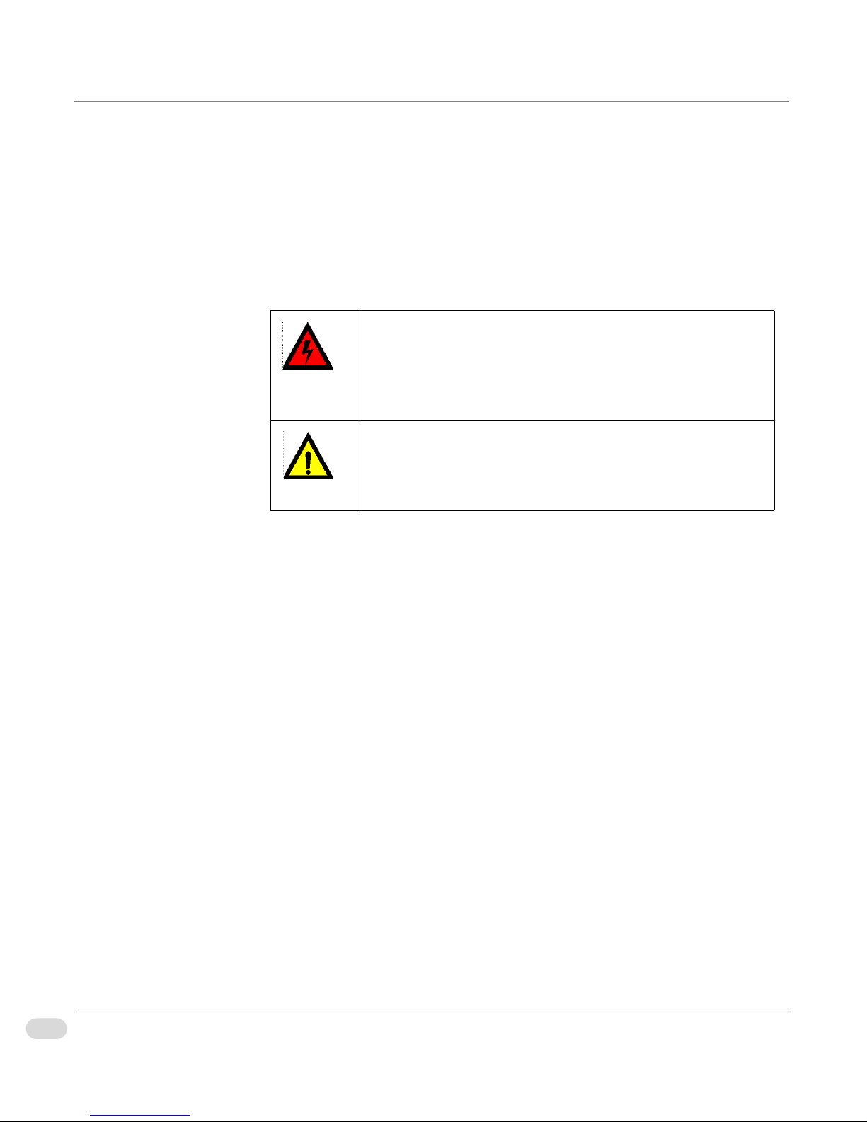
Table P-2. Safety Terms and Symbols
WARNING: Identifies conditions or practices that can
result in personal injury or loss of life—high voltage is
present. Uninsulated dangerous voltage within the product’s
enclosure may be sufficient to constitute a risk of electric
shock to persons.
CAUTION: Identifies conditions or practices that can result
in damage to the equipment or other property. Important
operating and maintenance (servicing) instructions are
included in the literature accompanying the product.
viii Preface
InfoCaster Rackmount Hardware Installation Manual
Page 13

Restriction on Hazardous Substances (RoHS) Directive
Directive 2002/95/EC–commonly known as the European Union (EU)
Restriction on Hazardous Substances (RoHS)–sets limits on the use of certain
substances found in electrical and electronic equipment. The Directive takes
effect on July 1, 2006, and it refers to the following hazardous substances:
• Lead (Pb)
•Mercury (Hg)
•Cadmium (Cd)
• Hexavalent Chromium (Cr-V1)
• Polybrominated Biphenyls (PBB)
• Polybrominated Diphenyl Ethers (PBDE)
All relevant Harris Corporation products either comply with the legislation or
are exempt. For example, spare parts supplied for the repair and upgrade of
equipment sold before July 1, 2006 are exempt from the legislation.
Figure P-1. RoHS Compliant Symbol
ixPreface
InfoCaster Rackmount Hardware Installation Manual
Page 14

Waste from Electrical and Electronic Equipment (WEEE) Directive
The European Union (EU) Directive 2002/96/EC on Waste from Electrical and
Electronic Equipment (WEEE) deals with the collection, treatment, recovery,
and recycling of electrical and electronic waste products. The objective of the
WEEE Directive is to assign the responsibility for the disposal of associated
hazardous waste to either the producers or users of these products. Producers
or users are required to recycle electrical and electronic equipment at end of its
useful life, and must not dispose of the equipment in landfills or by using other
unapproved methods.
In accordance with this EU Directive, Harris Corporation has affixed labels
indicating that such products must be properly recycled. Contact your local
Harris sales representative for information on returning these products for
recycling. Harris equipment that complies with the EU directive will be marked
with a WEEE-compliant symbol, as shown in Figure P-2.
xPreface
InfoCaster Rackmount Hardware Installation Manual
Figure P-2. WEEE Compliance Symbol
Page 15

Declaration of Conformity
Inscriber Graphics Systems declares that the following Inscriber turnkey system models are in conformity with
the standards stated in this note.
System Name Part Number Description
InfoCaster DS1000 INCSDS1000 Compact Digital Signage Platform
InfoCaster R1000 INCSR1000 Rackmount Digital Signage Platform
The Inscriber turnkey systems previously listed, are in conformity with the following standards, in accordance
with the 89/336EEC Electromagnetic Compatibility Directive.
EN55022 Limits and methods of
measurement of radio disturbance
characteristics of information
technology equipment
EN50081-1 Electromagnetic compatibility —
Generic emission standard —
Part 1: Residential, commercial,
and light industry
EN50082-1 Electromagnetic compatibility —
Generic immunity standard —
Part 1: Residential, commercial,
and light industry
EN55103-1 Electromagnetic compatibility —
Product family standard for audio,
video, audio-visual and
entertainment lighting control
apparatus for professional use —
Part 1: Emission
EN61000-4-2 Electrostatic discharge
requirements “ESD”, 6kV CD,
8kV AD
EN61000-4-3
EN61000-4-4 Electrical fast transient
requirements “Burst”, 0.5kV Sig.
Lines, IkV Power line
EN61000-4-5
EN55103-2 Electromagnetic compatibility —
Product family standard for audio,
video, audio-visual and
entertainment lighting control
apparatus for professional use —
Part 2: Immunity
EN61000-4-6
xiPreface
InfoCaster Rackmount Hardware Installation Manual
Page 16

EN61000-3-2 Electromagnetic compatibility —
EN61000-4-11
Part 3-2: Limits — Limits for
harmonic current emissions
(equipment input current up to
and including 16 A per phase)
EN61000-3-3 Electromagnetic compatibility —
Part 3-3: Limits — Limitation of
voltage changes, voltage
fluctuations, and flicker in public
low-voltage supply systems, for
equipment with rate current
<=16A per phase and not subject
to conditional connection
Inscriber Graphics Systems also declares the conformity of the previously mentioned products, with the
required safety standards, in accordance with LVD 73/23 EEC
.
EN60950 Safety for information technology
equipment including electrical
business equipment
xii Preface
InfoCaster Rackmount Hardware Installation Manual
Page 17

Safety Guidelines
Adhere to the following safety guidelines to avoid personal injury or damage to your system.
Electrical Safety Guidelines
Power Cords
• Use the exact type of power cords as required.
Warning
To avoid electrical shock, check
the power cords properly.
• Use power cord(s) that came with safety certifications.
• The power cord(s) must be compliant with the AC voltage requirements in
your region.
• The power cord plug cap must have an electrical current rating that is at
least 125% of the electrical current rating of this product.
• The power cord plug cap that plugs into the AC receptacle on the power
supply must be an IEC 320, sheet C13, type female connector.
• Disconnect the power supply before accessing the InfoCaster Rackmount
chassis or its components.
• Plug the power cord(s) into a socket that is properly grounded before
turning on the power.
Warning
Adhere to the following
Electrical Safety Guidelines to
avoid possible damages to the
system or injury to yourself.
General Electrical Safety Guidelines
• Be aware of the locations of the power switches on the chassis and in the
room, so you can disconnect the power supply if an accident occurs.
• Take extra precautionary measures when working with high voltage
components. It is not recommended to work alone.
• Before removing or installing main system components, be sure to
disconnect the power first. Turn off the system before you disconnect the
power supply.
• Use only one hand when working with powered-on electrical equipment to
avoid possible electrical shock.
• Use rubber mats specifically designed as electrical insulators when working
with computer systems.
• The power supply or power cord must include a grounding plug and must
be plugged into grounded outlets.
xiiiPreface
InfoCaster Rackmount Hardware Installation Manual
Page 18

• Motherboard Battery: CAUTION – Make sure not to install the onboard
battery upside down to avoid possible explosion. Make sure that the
positive side should be facing up on the motherboard. This battery must be
replaced only with the same or an equivalent type recommended by the
manufacturer. Dispose of used batteries according to the manufacturer's
instructions.
• CD-ROM Laser: CAUTION – Do not open the enclosures of power
supplies or CD ROM to avoid injury.
General Safety Guidelines
• Keep the area around the InfoCaster chassis clean and free of clutter.
Warning
Adhere to the following General
Safety Guidelines to ensure
your personal safety.
• To avoid injuries to the back, be sure to use your leg muscles, keep your
back straight, and bend your knees, when lifting the system.
• Avoid wearing loose clothing to preventing it from coming into contact
with power circuits.
• After removing the components or chassis covers from the system, place
them on a table for safeguard.
• Be sure to remove any jewelry or metal objects before working on the
chassis to avoid short circuits should these objects come into contact with
power circuits.
• After accessing the interior of the chassis, be sure to close the chassis with
the chassis covers and secure the chassis to the racks with screws.
ESD Safety Guidelines
The following measures are generally sufficient to protect against Electric
Caution
Electric Static Discharge (ESD)
can damage electronic
components. To prevent
damage to your system board, it
is important to handle it very
carefully.
xiv Preface
InfoCaster Rackmount Hardware Installation Manual
Statics Discharge (ESD).
• Use a grounded wrist strap designed to prevent static discharge.
• Keep all components and printed circuit boards (PCBs) in their anti-static
bags until ready for use.
• Touch a grounded metal object before removing the board from the
anti-static bag.
• Do not let components or PCBs come into contact with your clothing,
which may retain a charge even if you are wearing a wrist strap.
• Touch a grounded metal object before removing the board from the
anti-static bag.
Page 19

• Handle a board by its edges only; do not touch its components, peripheral
chips, memory modules or contacts.
• When handling chips or modules, avoid touching their pins.
• Put the motherboard and peripherals back into their anti-static bags when
not in use.
• For grounding purposes, make sure your computer chassis provides
excellent conductivity between the power supply, the case, the mounting
fasteners and the motherboard.
Operation Safety Guidelines
Adhere to the following safety guidleines to avoid personal injury when
accessing the InfoCaster Rackmount chassis.
1 Turn off all peripheral devices connected to the InfoCaster Rackmount
chassis.
2 Press the power button to power off the system.
3 Unplug all power cords from the system or wall outlets.
4 Disconnect all the cables and label the cables for easy identification.
Caution
For proper cooling, make sure
to install all chassis covers
before turning on the system. If
this rule is not strictly followed,
warranty may become void. Do
not open the casing of a power
supply. Power supplies can only
be accessed and serviced by a
qualified technician of the
manufacturer.
5 Use a grounded wrist strap designed to prevent static discharge when
handling components.
Ensure the following measures are in place before installing the chassis into a
rack.
• The rack must be securely anchored onto a unmovable surface or structure
before installing the chassis into the rack.
• The system must be adequately supported. Make sure that all the
components are securely fastened to the chassis to prevent components
from falling off from the chassis.
• Unplug the power cord(s) of the rack before installing the chassis into the
rack.
• Install an AC Power Disconnect for the entire rack assembly and this Power
Disconnect must be clearly marked.
• The rack assembly must be properly grounded to avoid electric shock.
• The rack assembly must provide sufficient airflow to the chassis for proper
cooling.
xvPreface
InfoCaster Rackmount Hardware Installation Manual
Page 20

xvi Preface
InfoCaster Rackmount Hardware Installation Manual
Page 21

Chapter 1
Introduction
Page 22

Overview
This chapter provides an introduction to the InfoCaster Rackmount Creation
Station and Player systems, including the following topics:
• “Product Description” on page 3
• “System Chassis” on page 4
• “Functional Block Diagram” on page 8
2 Chapter 1 | Introduction
InfoCaster Rackmount Hardware Installation Manual
Page 23

Product Description
The InfoCaster Rackmount turnkey system is your single source solution for high-impact digital signage.
InfoCaster Rackmount is an out-of-the-box communications solution that produces powerful, multi-zone
broadcast quality page layouts for immediate display on video monitors.
Main Features
These are the main features of InfoCaster Rackmount.
• Superior graphics: create multiple layers of independent bugs, crawls,
animations, clocks and more.
• Data integration: link on-air graphics with databases, data feeds, or text
files for automatic updates to keep the information current.
• Quick editors: modify content with fast and easy updates.
• Control Choices: GPI, automation, manual.
• Intuitive interface: drag and drop user interface makes it simple to learn
and allows users to get to air quickly.
• Multi-zone display: zones can be set up to display either, stills, rolls,
crawls, animations, clocks, or video. Each zone is an independent item,
and can be customized with different attributes.
• Live video input: DV or composite video playback using a 3rd party capture
device.
• Video output: support for MPEG1, MPEG2, MPEG4, AVI and Windows
Media video clips.
• Audio output: support for video clips, or add audio to a specific still zone.
• Animation: import and convert seqeunces of TGAs from third party
animation software.
• Flexible scheduling: powerful weekly scheduling of InfoCaster multi-zone
displays.
• Network Control (optional): manage up to hundreds of InfoCaster players
using the optional InfoCaster Network Manager.
3Chapter 1 | Introduction
InfoCaster Rackmount Hardware Installation Manual
Page 24

System Chassis
Front Panel
Figure 1-1 shows the InfoCaster Rackmount front panel. The front panel has two
LEDs indicating system status. See Tab l e 1 -1 for LED description.
O
I
RESET
POWER
PWR HDD
CD/DVD-RW DriveSystem Reset USB 1-2
Figure 1-1: Rackmount Front Panel
Front Panel LEDs
Table 1-1. Front Panel LED Description
LED Color Condition Description
Power Green On System On
HDD Red Blink HDD Activity
4 Chapter 1 | Introduction
InfoCaster Rackmount Hardware Installation Manual
Floppy DrivePower Status LEDs
Off No Activity
Page 25

Back Panel
Figure 1-2 illustrates the InfoCaster Rackmount back panel configured with the
maximum options. Note that the exact component placement on your system
may vary slightly depending on your system specifications.
I
O
Power Supply
PC Ports
Analog Capture
(optional)
S-VideoDVI / VGA
GPIO
(optional)
Audio I/O
(optional)
Figure 1-2: Rackmount Back Panel
Back Panel Connections
Ta bl e 1 - 2 lists and describes the functions of the back panel connectors.
Table 1-2. Back Panel Connectors Description
Port Description
DVI/VGA Digital (DVI) and analog (VGA) video output.
S-Video Composite video output.
Analog Capture (optional) Live or captured video stream input.
GPIO (optional) Enables GPI triggers for controlling output.
Audio I/O (optional) 7.1 surround sound audio card.
InfoCaster Rackmount Hardware Installation Manual
5Chapter 1 | Introduction
Page 26

Back Panel PC Ports
r
Figure 1-3 illustrates the back panel PC ports.
LAN 1-2 Center BassIEEE 1394COM 1Mouse
Rear Speaker
Line In
Front Speake
Mic In
Keyboard Coaxial
Out
PC Port Connections
Ta bl e 1 - 3 lists and describes the functions of the back panel PC ports.
Table 1-3. PC Ports Descriptions
Port Description
PS/2 Mouse (green) Connects a PS/2 mouse.
COM1 Serial 9-pin COM1 port for serial devices.
IEEE 1394 6-pin IEEE 1394 port provides high-speed connectivity
LAN 1-2 (RJ-45) Enables Gigabit connection to a Local Area Network
Center/Subwoofer
(orange)
USB 1-4 Side SpeakerSATAOptical
Out
Figure 1-3: Back Panel PC Ports
for audio/video devices, storage peripherals, PCs, or
portable devices.
(LAN) through a network hub. See Table 1-4 on page 7
for LAN port LED descriptions.
Connects the center/subwoofer speakers.
Rear Speaker Out
(black)
Line In (light blue) Connects audio input devices.
6 Chapter 1 | Introduction
InfoCaster Rackmount Hardware Installation Manual
Connects the rear speakers in a 4-channel, 6-channel,
or 8-channel audio configuration.
Page 27

Table 1-3. PC Ports Descriptions (Continued)
Port Description
Line Out (lime) Connects the front speakers in a 4-channel, 6-channel,
or 8-channel configuration.
Mic In (pink) Connects a microphone.
Side Speaker Out
(grey)
Connects the side speakers in a 8-channel
configuration.
USB 1-4 Connect up to four Universal Serial Bus (USB) 2.0
devices.
External SATA Connects to an external SATA box or a Serial ATA
port mutiplier.
Optical S/PDIF Out Audio output via an optical S/PDIF cable.
Coaxial S/PDIF Out Audio output via a coaxial S/PDIF cable.
PS/2 Keyboard Connects a PS/2 keyboard.
LAN Port LEDs
Ta bl e 1 - 4 describes the status of the LAN LEDs. The left LED indicates the
network connection status. The right LED indicates the connection speed.
Table 1-4. LAN LED Descriptions
Link LED Status
(left side)
Description
Speed LEDStatus
(right side)
Description
Off No Link Off 10 Mbps
Amber Linked Amber 100 Mbps
Blink Data Activity Green 1 Gbps
7Chapter 1 | Introduction
InfoCaster Rackmount Hardware Installation Manual
Page 28

Functional Block Diagram
The following block diagram illustrates the InfoCaster system configured with the maximum options.
Back Panel I/O
Intel Core Duo/
Intel Core 2 Duo
CPU
DIMM4: Socket 240-pin
DDR2-667
DIMM3: Socket 240-pin
DDR2-667
DIMM2: Socket 240-pin
DDR2-667
DIMM1: Socket 240-pin
DDR2-667
DDR2-667 144-bit
Intel G975X Chipset
PCI-Express x 16
Slot 1
ATI
PCI-Express
GPU
ATI
PCI-Express
GPU
VGA/DVI #1
VGA/DVI #2
VGA/DVI #3
VGA/DVI #4
SATA
SATA
SATA
HDD
HDD
HDD
SATA
0,1,2,3
CD/
DVD-
RW
IDE
Primary
ATA133
System Power
Supply
S-ATA/300
FDD
USB GPIO
Option
SATA
USB TV Tuner
Option
Digiatl Audio
USB V2.0
Intel
ICH-7 (R)
Super I/O
* Items In dotted line are optional. Please refer to your system specification
HD-Audio Analog Audio I/O
Parallel Port
for exact system specification
AC97/
HD-Audio
Codec
PCI-E Gigabit
PCI-E Gigabit
1394
LAN # 1
LAN # 2
GPIO (24 Port)
TV Tuner
(RF Input)
HASP
USB
1 ~ 4
E-SATA port
AC97/6-ch
Audio
HD Audio 7.1
Coax and Optical out
1394
Gigabit LAN #1
RJ45
Gigabit LAN #2
RJ45
Parallel Port
PS/2 Keyboard
PS/2 Mouse
100-240 AC
Full Range
8 Chapter 1 | Introduction
InfoCaster Rackmount Hardware Installation Manual
Page 29

Chapter 2
Installation and Setup
Page 30

Overview
This chapter provides information about installing and setting up your InfoCaster Rackmount Creation
Station or Player.
The following topics are included in this chapter:
• “Chassis Rack Mount” on page 11
• “InfoCaster System Options” on page 15
• “GPI Triggers” on page 17
• “Video Output Card” on page 20
• “Video Setup Options” on page 25
• “Audio Setup Options” on page 31
• “Work with Network Manager” on page 32
10 Chapter 2 | Installation and Setup
InfoCaster Rackmount Hardware Installation Manual
Page 31

Chassis Rack Mount
The InfoCaster Rackmount system must be mounted in an area where there is unrestricted air movement. For
maximum efficiency and reliability, the InfoCaster system should be operated in an ambient temperature
between 40° and 95°F (5° to 35°C) non-condensing.
Structural
Support
Along with the rack mounting ears included in the packing box, InfoCaster
Rackmount systems require additional structural support.
Inscriber does not provide rack mounting slides as a standard part of the
system accessories. You can order slides for your InfoCaster Rackmount chassis
from Inscriber.
Inscriber has tested and approved the Chassis Trak
mounting slides from General Devices. These slides are available in various
lengths to meet your rack mounting requirements, and are designed to support
the weight of a fully configured InfoCaster system. Other manufacturers can
provide equivalent rack slides, but these rack slides are not tested for use with
Inscriber systems.
Sources for Rack Mounting Slides
Inscriber tested and approved:
• General Devices – http://generaldevices.thomasnet.com/Category/
solid-bearing-slides
Additional sources of rack mounting slides:
• Accuride – http://www.accuride.com/index2.php
®
Model C-300 rack
• Above Board Electronics – http://www.aboveboardelectronics.com/
• Holly – http://www.hollyintl.com/rackmount.htm
• Surplus Sales – www.surplussales.com/Cab-RacksHardware/
accuride/rm_accessories.html
ChassisSlides.html
11Chapter 2 | Installation and Setup
InfoCaster Rackmount Hardware Installation Manual
Page 32

Chassis Slides
Installation
Warning
To avoid personal injury and
property damage, please adhere
to all safety steps.
The following installation procedure is for the General Devices slide assembly.
If you purchase another brand of chassis slides, follow the instructions
provided with that product.
Before you install the chassis in the rack, make sure that the chassis cover is in
place, and the slides are attached to both the chassis and the rack.
Before installing the chassis slides:
1 Ensure that the chassis covers are in place.
2 Unplug the AC power cord(s).
3 Remove all external devices and connectors.
Installing the Slides
Included in the shipping package are a pair of slide assemblies and assocciated
hardware. Each slide assembly includes an inner, intermediate, and outer slide.
The assemblies are identical, and can be installed on either side of the chassis.
1 Lift the extension lock lever to release the inner slide from its locked
position and pull the inner slide out from the assembly.
Extension Lock
Inner Slide
(attach to chassis)
12 Chapter 2 | Installation and Setup
InfoCaster Rackmount Hardware Installation Manual
Outer Slide
(installed on rack)
Intermediate Slide
Figure 2-1. Chassis Slide Assembly
Page 33

2 Locate the four threaded screw holes on each side of the chassis and align
them with the first four holes of the inner slides.
Screw Holes
Mounting Screws
Figure 2-2. Slide Mounting
3 Secure the slide to the chassis with the supplied screws.
4 Repeat the above steps to install the other inner slide on the opposite side
of the chassis.
13Chapter 2 | Installation and Setup
InfoCaster Rackmount Hardware Installation Manual
Page 34

Rack Installation
r
After you have installed the inner slides on the chassis, you are ready to install
the outer slides to the rack.
1 Insert the intermediate slide fully into the outer slide from the rear until it
locks in place.
2 Secure an end bracket and a bar nut to the rear of the outer slide with the
screws provided.
Rack Rea
End Bracket
Outer Slide
Rack Front
Bar Nuts
Warning
To avoid injury, lifting the
chassis requires two people.
Figure 2-3. Rack Installation
3 Secure the outer slide end bracket assembly to the rear of the rack with a
bar nut and the screws provided.
4 Secure the front of the outer slide to the front of the rack with a bar nut
and the screws provided.
5 Repeat the above steps to install the other outer slide on the opposite side
of the rack.
6 Slide the chassis into the rack. Some adjustment to the slide assemblies
might be needed as the chassis may not slide into the rack smoothly or
easily when installed the first time.
7 In order to completely remove the chassis from the rack, you need to press
the release tabs on both sides of the chassis.
14 Chapter 2 | Installation and Setup
InfoCaster Rackmount Hardware Installation Manual
Page 35

InfoCaster System Options
InfoCaster is designed to run continuously on your system, which makes the application available to play
InfoCasts at any time. Since InfoCaster Rackmount is designed to run without interruption, you must turn off
certain system settings such as screen savers and monitor power saving options that interrupt InfoCaster
operations.
Confirm Your
Administrator
Privileges
Turn Off Windows
Automatic
Updates
You must have administrator privileges to install InfoCaster. Complete the
following steps to confirm your administrator privileges.
1 Login to your computer with your username and password.
If the computer is in a Workgroup, the password must not be left blank.
2 Select Start
• If the computer is in a domain, the login account is listed in Users.
Check that Administrators displays under the Group heading.
• If the computer is not in a domain, Computer Administrator displays
beside your login account.
3 If you do not have administrator privileges, contact your IT professional.
Windows Automatic Updates reboots the system when an update arrives,
interrupting your output. Use the following steps to turn off Windows
Automatic Updates.
1 Right-click on My Computer.
2 Select Properties from the menu.
3 Switch to the Automatic Updates tab.
> Control Panel > User Accounts.
4 Select the Turn off Automatic Updates radio button.
5 Click the Apply button and then click OK.
Turn Off the
Screen Saver
If a screen saver turns on after a period of inactivity, the InfoCaster output goes
blank. For InfoCaster to run properly, you must turn off the screen saver.
1 Right-click on the Windows desktop.
2 Select Properties from the menu to open the Display Properties dialog.
3 Switch to the Screen Saver tab.
4 On the Screen Saver drop-down list, select (None).
5 Click the Apply button and then click OK.
15Chapter 2 | Installation and Setup
InfoCaster Rackmount Hardware Installation Manual
Page 36

Turn Off Monitor
Power Saving
Options
To avoid losing your video output you must turn off the monitor power saving
option. If the monitor power saving option interrupts InfoCaster operations
your video output goes blank and your computer screen turns black. To regain
your video output, your must restart your computer. Complete the following
steps to turn off your monitor power saving option and ensure you do not lose
your video output.
1 Right-click on the Windows desktop.
2 Select Properties to open the Display Properties dialog.
3 Switch to the Screen Saver tab.
4 Click on the Power button to open the Power Schemes and Settings dialog.
5 From the Turn Off Monitor drop-down list, select Never.
6 Click the Apply button and then click OK.
Turn Off Simple
File Sharing
In Windows XP, ensure Simple File Sharing is NOT enabled.
1 Click on Start > Control Panel.
2 Double-click on Folder Options.
3 In the Folder Options window, switch to the View tab.
4 Scroll to the bottom of the Advanced settings list.
5 Ensure Use simple file sharing is NOT selected.
6 If Use simple file sharing is selected, clear the checkbox and click OK.
16 Chapter 2 | Installation and Setup
InfoCaster Rackmount Hardware Installation Manual
Page 37

GPI Triggers
InfoCaster Rackmount supports serial or USB GPI triggers for controlling output. The GPI trigger type allows
you to trigger each event with an external button press. The GPI takes the voltage from a serial port pin to
close a switch and complete the circuit, triggering the selected event.
Serial Port GPI
Trigger
Figure 2-4 shows the pin closures for 25-pin and 9-pin serial port connectors.
Reverse movement is not supported.
Figure 2-4. Serial Port Connectors
Serial port GPI triggers need to be added to the GPI list in the Configuration
Utility before they can be used in InfoCaster. See “External Triggers Tab” in
Appendix B in the InfoCaster User Guide for more information.
17Chapter 2 | Installation and Setup
InfoCaster Rackmount Hardware Installation Manual
Page 38

USB GPI Trigger
InfoCaster Rackmount supports GPI triggers connected to the USB U2IO
device for controlling output. The U2IO device supports 14 GPI connections
and 10 GPO connections.
Figure 2-5 shows the GPI pin connectors for the U210 device.
9
18
26 19
1. GPI 1
2. GPI 2
3. GPI 3
4. GPI 4
5. GPI 5
6. GPO 1
7. GND
8. GPO 2
9. GPO 3
10. GPI 6
11. GPI 7
12. GPO 4
13. GPI 9
14. GPI 8
15. GPO 5
16. GPO 6
17. GPO 7
18. GPO 8
Pin
1
10
19. GPI 10
20. GPI 11
21. GPO 9
22. GPI 14
23. GPI 13
24. GPI 12
25. VCC - MPU
26. GPO 10
Figure 2-5. USB GPI Connector Pinout
The GPI inputs are TTL. The GPIO device expects TTL transition from High to
Low to initiate a GPI trigger. The GPI triggers can be initiated by using passive
switch, or relay with normally open contacts.
GPI inputs 9-14 have no internal pull-up resistors. If passive switching is
required for GPI inputs 9-14 the pull-up resistors must be added externally.
18 Chapter 2 | Installation and Setup
InfoCaster Rackmount Hardware Installation Manual
Page 39

Figure 2-6. GPI Passive Switch Connection
When systems are connected through a USB port, you can set an event on one
system to trigger an event on another system. See “Use Triggers to Play Other
InfoCasts” in Chapter 6 in the InfoCaster User Guide for more information.
USB GPI triggers need to be added to the GPI list in the Configuration Utility
before they can be used in InfoCaster. See “External Triggers Tab” in Appendix
B in the InfoCaster User Guide for more information.
19Chapter 2 | Installation and Setup
InfoCaster Rackmount Hardware Installation Manual
Page 40

Video Output Card
InfoCaster Rackmount supports ATI Radeon output card models X1600, X1650, or better. These ATI cards
provide excellent video quality for progressive output up to 1280 x 768.
Connect the
Output Cables
Set Up the Display
Output
1 Turn off the computer. Connections are not detected by the system if you
connect the cables when the computer is turned on. Select one of the
following output monitor options.
• Connect a DVI output monitor to the DVI connector. This system is
configured to support dual DVI monitoring.
• Connect the computer VGA monitor to the DVI output using a VGA
adapter.
2 Turn on the computer. If InfoCaster is already installed on your system, do
NOT open InfoCaster until you have configured the output monitor. The
system might generate an error if InfoCaster is opened without a properly
configured output monitor.
3 Turn on the output monitor and make sure it is not in standby mode.
Single Head Output
Single head output is used to display a player’s output on a single monitor.
Instead of connecting a second output device to the ATI card in your player
system, you can simply use the monitor of your player system as your output
monitor.
The ATI card does not need to be specially configured for single head output.
Note: Once your player has started playback in single head mode you will be
Spanning, Edit & Playback, or Multi Head Output
To configure the ATI card for Spanning, Edit & Playback, or Multi Head output,
use the ATI Catalyst Control Center.
• Spanning output is used to display a player’s output across two VGA
• Edit & playback output allows you to edit InfoCasts on one monitor and
20 Chapter 2 | Installation and Setup
InfoCaster Rackmount Hardware Installation Manual
unable to return to the desktop without shutting down InfoCaster. If you
need to switch back to the desktop at any time press the
CTRL+ALT+SHIFT+HOME key combination.
monitors. Only one InfoCast can be displayed at a time.
display them on the other. Only one InfoCast can be displayed at a time.
Page 41

If you do not have the Catalyst Control Center you can also set up Edit &
Playback output using the Windows Properties dialogs. See “Set Up Edit &
Playback Without Catalyst Control Center” on page 23.
• If you have the Multi Head option, use this option when you want to
operate two players on a single system. Each player instance displays its
output on a separate monitor. With this configuration two InfoCasts can be
displayed at the same time.
Disable the Onboard VGA
If your computer motherboard has an onboard VGA there can be resource
conflicts with the ATI card. The onboard VGA must be disabled. Check the
documentation included with your computer to find out if the motherboard has
an onboard VGA, or ask your system administrator for assistance. Your system
administrator must disable the onboard VGA in the computer BIOS, and in
Windows XP.
Note: After running any other video enabled application, you must reboot the
computer before running InfoCaster.
Configure Display
Settings
Follow these instructions to configure your display settings.
1 Connect and turn on the second monitor.
2 Right-click on the Windows desktop.
3 Select Properties to open the Display Properties dialog.
4 Switch to the Settings tab.
5 Click on the Advanced button. A display configuration dialog opens.
6 In the display configuration dialog, switch to the Catalyst Control Center
tab.
21Chapter 2 | Installation and Setup
InfoCaster Rackmount Hardware Installation Manual
Page 42

7 Click on the Catalyst Control Center button.
Figure 2-7. Catalyst Control Center
Note: When you first launch the Control Center you are prompted to
select the mode you wish to work in. Select Advanced mode.
8 Click on Displays Manager.
9 Click on the Detect Displays button to confirm the setup.
10 Click on the monitor 2 icon to open the display settings panel.
11 If you are setting up Multi Head or Spanning VGA output:
a Select your desktop area from the drop-down list.
b Right-click on monitor 2 and select Stretch Main horizontally onto
monitor.
c Click Apply.
22 Chapter 2 | Installation and Setup
InfoCaster Rackmount Hardware Installation Manual
Page 43

12 If you are setting up Edit & Playback VGA output:
a Select your desktop area from the drop-down list.
b Right-click on monitor 2 and select Extend Main onto monitor.
c Click Apply.
13 Click on Done and close the Catalyst Control Center and the Display
Properties dialog.
Set Up Edit & Playback Without Catalyst Control Center
If you have just the ATI drivers and no Catalyst Control Center, follow these
instructions to configure Edit & Playback output.
1 Turn on the second monitor.
2 Right-click on the Windows desktop.
3 Select Properties to open the Display Properties dialog.
4 Switch to the Settings tab.
Figure 2-8. Display Properties Settings Tab
23Chapter 2 | Installation and Setup
InfoCaster Rackmount Hardware Installation Manual
Page 44

5 Select the monitor 2 icon.
6 Ensure your ATI card is listed under Display. If the ATI card is not listed:
a Click on the Advanced button.
b Switch to the Monitor tab.
c Click on the Properties button.
d Select Use this device (enable) from the Device usage drop-down list.
e Click on OK, then OK again to return to the Settings tab.
7 Select the Extend my Windows desktop onto this monitor checkbox.
8 Click on the Advanced button.
9 Switch to the Displays tab.
10 Select Monitor, and click Apply.
24 Chapter 2 | Installation and Setup
InfoCaster Rackmount Hardware Installation Manual
Page 45

Video Setup Options
Before you configure the audio and video options, make sure the InfoCaster software is installed on your
system, and that you have configured the video output card.
Typically, the software is already installed on your system, however, if you need to install, or reinstall the
software, see “Install InfoCaster Software” in Chapter 1 of the InfoCaster User Guide.
Configuration
Utility
After confirming that the software is installed, open the InfoCaster
Configuration Utility.
1 Select Start > Programs > Harris > InfoCaster > Configuration Utilities >
InfoCaster Configuration Utility.
2 Switch to the Video/Audio Standard tab to set up your video and audio
options. If you have the Multi Head option, use the Video/Audio Standard
tab to set up multiple VGA Out player instances.
Figure 2-9. Video/Audio Standard Tab
25Chapter 2 | Installation and Setup
InfoCaster Rackmount Hardware Installation Manual
Page 46

Select the Video
Output Device
Select your output device from the Select Output Device drop-down list.
Depending on your system’s output card, some options in the list are not
selectable.
Table 2-1. Output Devices
Device Description
Set the Video
Standard
Set Device Output
Options
Desktop Video
Window
The desktop video window displays player output in a
window on your system’s VGA monitor. This window can
be repositioned within the desktop and can be minimized
when not in use.
This option does not require any output hardware. It is not
intended for presentation and is best used for creating and
previewing new InfoCasts.
VGA Out VGA Out displays player output on one or more external
VGA monitors. See ”Configure VGA Output” on page 28
to learn how to set up single or multi head output.
Use the Video Standard drop-down list to select the video standard for desktop
video output. The options available depend on the output device you are using,
but generally include PAL and NTSC standards.
Note: When using the VGA Out option, the Video Standard drop-down list
does not appear. Set your video standard for VGA Output as described
in ”Configure VGA Output” on page 28.
Depending on your output device you can customize your output options using
the available checkboxes.
Table 2-2: Device Output Options
Option Description
Use GPU
Acceleration
26 Chapter 2 | Installation and Setup
InfoCaster Rackmount Hardware Installation Manual
Desktop Video provides a Use GPU Acceleration
checkbox. To improve video output quality and speed,
InfoCaster can tell your video card to perform many of
the output tasks that InfoCaster would otherwise perform
itself.
Select the Use GPU Acceleration checkbox if your video
card is capable of handling advanced video output tasks.
Page 47

Table 2-2: Device Output Options (Continued)
Option Description
Confidence
Preview
Supports
Touchscreen
Desktop Video and VGA Out provide a Confidence
Preview checkbox. Select it to enable Network Manager
and InfoCaster to display thumbnails of player output.
Confidence Previews are CPU and GPU intensive.
VGA Out provides a Supports Touchscreen checkbox. If
your output monitor has touch screen capabilities, select
this checkbox to allow InfoCaster to detect screen
touches.
To use this feature within InfoCaster, enable a region to
detect a touch and assign that region to a Conditional
Playback trigger.
To set up a touch screen:
1 Connect the touch screen monitor to your system.
2 Right-click on your computer desktop and select
Properties.
3 Switch to the Settings tab.
4 Set up the touch screen so that it is the first head.
5 Within the InfoCaster Configuration Utility, set
InfoCaster to output to that head. Set the other head
as the Windows desktop.
DirectX Yield
Technique
VGA Out provides a DirectX Yield Technique drop-down
menu to control video output. The default selection
(Query) is the most efficient, but it is not supported on
some cards.
Try the other yield techniques only if you are
experiencing serious output problems.
27Chapter 2 | Installation and Setup
InfoCaster Rackmount Hardware Installation Manual
Page 48

Configure VGA
Output
After you have installed and set up the VGA card in your system, select the
VGA Out output device from the drop-down list to begin configuring one or
more VGA displays.
Figure 2-10. Multi Head VGA Output Setup
If you have the Multi Head option you can run multiple instances of InfoCaster
on your system, each one displaying output on a different card head. Network
Managers can update and control each instance separately, and many of the
Configuration Utility tabs allow you to separately configure each instance.
VGA Setup Workflow
1 Before starting, install and configure the VGA card in your system.
See ”Video Output Card” on page 20 to learn more about ATI cards. You
may need to consult your card’s documentation or your IT professional for
more information.
2 Within the Video/Audio Standard tab, select the VGA Out device from the
Select Output Device drop-down list.
3 Set the video standard and rotation for the card.
4 Click the Update button to finalize the settings for the selected card.
5 Use the Add and Remove buttons to set the heads provided by the card.
InfoCaster and Network Manager consider each head to be an instance.
Each head can display separate InfoCasts, and heads can be combined
together to span InfoCasts across multiple monitors.
Note: Any time you change the settings of a card, click the Update button
to finalize the changes.
6 If you want to be able to edit InfoCasts and control output locally on this
system, select the head you want to want to use for editing, and select the
Set This Head as Windows Desktop checkbox.
28 Chapter 2 | Installation and Setup
InfoCaster Rackmount Hardware Installation Manual
Page 49

Table 2-3: Common VGA Out Configurations
Configuration Description
Spanning Spanning output is used to display a player’s output
across two monitors. Only one InfoCast can be
displayed at a time.
In the InfoCaster Configuration Utility, configure one
instance and do not select the Windows Desktop
checkbox. The instance must be set with a custom
resolution that matches the total size of both monitors.
For example, if you are spanning across two 1024 x 768
monitors, set the instance resolution to 2048 x 768.
Edit & Playback Edit & Playback output is used when you want to edit
InfoCasts on one monitor and display them on the
other. Only one InfoCast can be displayed at a time.
To set up Edit & Playback output, configure two
instances. Select the instance you want to use for the
InfoCaster program and select the Windows Desktop
checkbox. The other instance is used for displaying the
player’s output.
Single Head Single Head output is used to display a player’s output
on a single monitor.
To set up single head output, configure one instance
and do not select the Windows Desktop checkbox.
Multi Head If you have the Multi Head option, multi head output is
used when you want to operate two players on a single
system. Each player instance displays its output on a
separate monitor. With this configuration two InfoCasts
can be displayed at the same time.
To set up multi head output, configure two instances
and do not select the Windows Desktop checkbox. Each
instance outputs to a different monitor, and Network
Manager controls each instance separately.
InfoCaster Rackmount Hardware Installation Manual
29Chapter 2 | Installation and Setup
Page 50

Confirm the Video
1 After configuring your video output, click OK to save your settings.
Output
A warning dialog appears stating that all Harris software will shut down
and restart when exiting the InfoCaster Rackmount Configuration Utility.
Figure 2-11. Software Shutdown Warning
2 Click OK to continue with the setup. An ICConfig dialog appears asking if
you want to test your settings.
Figure 2-12. Settings Test Dialog
3 Click Yes to open the Test Pattern Output dialog.
4 Click the Start button and then OK when you see the color bars on your
output monitor.
Figure 2-13. Test Pattern Output Dialog
5 Click Yes on the Output Test dialog to confirm the color bars appeared
correctly, and to close the configuration utility.
If you did not see the color bars, return to “Select the Video Output
Device” on page 26 to reconfigure your video output.
30 Chapter 2 | Installation and Setup
InfoCaster Rackmount Hardware Installation Manual
Page 51

Audio Setup Options
Enable Live Audio
Input
Enable Audio
Output
Configure the
Audio I/O
If you have audio/video capture cards installed on your system, select the
Enable Live Audio/Video Input checkbox on the Video/Audio Standard tab in
the InfoCaster Configuration Utility. If you select this option, InfoCaster
enables you to use audio input from the cards within your Live Video regions.
If the capture card you wish to use is a PCI-100 or XD-200 card, select the
appropriate radio button. Otherwise, select the Third-Party Card radio button
and select the video standard from the drop-down list.
In order for your InfoCaster system to output audio, select the Enable Audio
Output checkbox on the Video/Audio Standard tab. When selected, InfoCaster
uses the default audio device currently set up within Windows.
Use the Sounds and Audio Devices control panel to change the Windows
default audio device and to configure your audio settings.
1 Select Start > Settings > Control Panel > Sounds and Audio Devices.
2 Select the Audio tab.
3 In the Sound playback section, select the audio card from the Default
device drop-down list.
4 Click the Advanced button and select the Speakers tab in the Audio
Properties window.
5 Select a speaker setup from the drop-down list.
The audio ports function changes depending on the channel configuration.
The following table lists the function of the audio ports in all configurations.
Table 2-4. Audio Channel Configuration
Port Color
Light Blue Line In Line In Line In Line In
Lime Line Out Front Speaker Out Front Speaker Out Front Speaker Out
Pink Mic In Mic In Mic In Mic In
Grey — — — Side Speaker Out
Black — Rear Speaker Out Rear Speaker Out Rear Speaker Out
Orange — — Center/Subwoofer Center/Subwoofer
2-Channel
(Stereo)
4-Channel
(Quadrophonic)
6-Channel
(5.1 Surround)
8-Channel
(7.1 Surround)
31Chapter 2 | Installation and Setup
InfoCaster Rackmount Hardware Installation Manual
Page 52

Work with Network Manager
InfoCaster systems work either as stand-alone creation stations, or as part of a network of multiple systems
comprised of creation stations and players controlled by Network Manager.
Creation Station
Player
InfoCaster systems behave as either creation stations or players, depending on
their current modes and dongle settings.
Creation stations create and edit your InfoCaster projects, called InfoCasts,
which include page layout, content, and scheduling. When connected to output
hardware, stand-alone creation stations can output InfoCasts to a single
location.
Creation stations can also send InfoCasts to multiple locations by publishing
them to Network Manager, and then Network Manager sends the InfoCasts to
one or more players. When connected to Network Manager, the creation station
video output channel can be used as a preview channel before publishing an
InfoCast.
Creation stations can run as players by selecting Tools > Run as Player. When
running as a player, InfoCaster has limited permission and cannot publish
InfoCasts.
Players are configured to receive InfoCasts and play them using their output
hardware. Network Manager sends commands to the player(s), instructing them
to download InfoCasts and play them at a specified time.
Players are primarily set up for hands-off, scheduled display of InfoCasts, but
creation station and Network Manager operators can give players some editing
permissions.
Network Manager
32 Chapter 2 | Installation and Setup
InfoCaster Rackmount Hardware Installation Manual
Network Manager defines what player(s) the presentation is intended for and
when it needs to arrive. The Network Manager then publishes the necessary
files to a specified file server location (such as a high bandwidth server) and
notifies the specific player(s) to retrieve the presentations from the file server.
For detailed information on setting up your InfoCaster system to work with
Network Manager, see “Connect InfoCaster to Network Manager” in Chapter 1
of the InfoCaster User Guide.
Page 53

Chapter 3
Maintenance
Page 54

Overview
This chapter provides information about the following topics:
• “Back Up Files” on page 35
• “Defragment Hard Drive” on page 35
• “Prevent Damage and Malfunction” on page 36
• “System Restore” on page 37
34 Chapter 3 | Maintenance
InfoCaster Rackmount Hardware Installation Manual
Page 55

Back Up Files
You should back up your files on a regular basis.
As you work with your system, you create work files that are typically saved to
your hard drive. You should make a copy of these files to use as a back up in
case your hard drive stops functioning properly. Use the network connection to
make back up copies.
The system provides different options to back up your files.
• Use the CD/DVD-RW drive and the backup software supplied with your
• Use a network connection.
Before you copy your files onto DVD, make sure that you have enough blank
DVDs to hold the files. The DVD-RW drive supports both writable and
rewritable DVDs.
For instructions on how to use the backup software supplied with your system,
use the online help included with the program.
system.
Defragment Hard Drive
You should defragment your hard drive regularly. Select Start > Programs >
Accessories > System Tools > Disk Defragmenter to open the utility included
with the operating system. Follow the instructions included in the operating
system online help.
35Chapter 3 | Maintenance
InfoCaster Rackmount Hardware Installation Manual
Page 56

Prevent Damage and Malfunction
Read and observe all instructions in this section to keep your system working safely and effectively.
Hardware
Software
Monitor Refresh
Rate
Do NOT modify the hardware. Your system is delivered with all the necessary
hardware and software already installed. You should not have to open the
system case. However, if the system case is damaged, please call Inscriber
Technical Support and follow their direct instructions to open the top of the
unit and verify that all components are still properly seated and connected.
Installing additional hardware or modifying the hardware in any way can
compromise the uninterrupted operation of your system.
Do NOT add software. Your system is a closed system. Do not install any
additional third party software. Additional software can create undesired effects
and possibly introduce viruses to the system. If you install additional third party
software your system may no longer run satisfactorily.
The factory sets the system graphical resolution to 1152 X 864 pixels with a
vertical refresh rate of 75Hz. If your computer monitor is an older model that
does not support a refresh rate of 75Hz, your display could be unusable and
you could damage your hardware. You need to change the system refresh rate to
a value that your monitor does support.
36 Chapter 3 | Maintenance
InfoCaster Rackmount Hardware Installation Manual
Page 57

System Restore
The restore process returns your system to the original factory settings. When
you ordered your system, you provided details about your application on the
system configuration sheet. Your system is set up according to this
configuration sheet.
Before you start the restore process, back up all of your files. See “Back Up
Files” on page 35 for details. The restore process completely overwrites the
hard drive that contains your system files. Any additional media drives in your
system are not overwritten.
The restore process does not restore any unsupported third-party software or
personal preferences in the Windows operating environment. Changes made to
settings, or patches installed after delivery are not restored.
System Restore
DVD
Restore
Procedure
The restore procedure requires the System Restore DVD that was delivered
with your system. Harris maintains a duplicate copy of your System Restore
DVD. If diagnostics are required, your system can be recreated at the factory
using the duplicate System Restore DVD.
To restore your Inscriber system, complete the following steps.
1 Create a back up copy of all your files.
2 Make sure there is no floppy disk in the floppy disk drive.
3 Place the System Restore DVD in the DVD-ROM drive.
By default, your system is configured to look for boot instructions on DVD
before checking the hard drive. If your system does not boot from the
DVD, have your system administrator confirm that the DVD comes before
the hard drive in the boot sequence.
4 Turn off the system.
5 Wait at least four seconds and then turn on the system.
6 When the copyright notice displays, press any key to continue when the
prompt appears.
7 Confirm that destination partition/drive size of the restore is correct.
8 Click Proceed to overwrite the partition.
If the system is not fully operational when the restore is complete, verify that
you did not make any incompatible hardware changes.
37Chapter 3 | Maintenance
InfoCaster Rackmount Hardware Installation Manual
Page 58

38 Chapter 3 | Maintenance
InfoCaster Rackmount Hardware Installation Manual
Page 59

Chapter 4
Specifications
Page 60

Overview
This chapter provides systems specifications, and includes the following topics:
• “System Technical Specifications” on page 41
• “Power Supply Specifications” on page 42
40 Chapter 4 | Specifications
InfoCaster Rackmount Hardware Installation Manual
Page 61

Specifications
System Technical Specifications
Ta bl e 4 - 1 details your system’s technical specifications.
Table 4-1. System Technical Specifications
Item Specification
Chassis • 4RU Rackmount Chassis
Operating System • MS Windows XP
Mouse • MS Optical PS/2
Floppy Drive • 1.44 MB
Keyboard • 104-key System PS/2
• Dimensions:
Height: 7”(17.78 cm)
Width: 19” (48.26 cm)
Depth: 21” (53.34 cm)
Weight 45 lbs (20.41 kg)
Network Port • Dual Gigabit Ethernet port via RJ45 connector, supports
10/100/1000 LAN Protocol: Microsoft Network
(NETBEUI), Novell (IPX), Unix/Internet (TCP/IP)
Serial Ports • One RS-232 serial port via DB-9 connector
Firewire • IEEE-1394 Port
Optical Drive • Recordable DVD-RW for backup or system restore
USB Ports • Six Hi-Speed USB 2.0 ports
(2 front panel, 4 back panel)
CPU • AMD Athlon 64 3800
GPU • ATI x1650 512 MB or better
RAM • 1 GB RAM
Boot Hard Drive • 80 GB IDE
Hard Drive • 2 x 160GB SATA (minimum)
System Restore • Bootable restore DVD to return system to factory
configuration
Operating
Te mp er a tu re
Relative Humidity • 5 - 95 % (non condensing)
• 40 - 95° F (5 - 35° C)
41Chapter 4 | Specifications
InfoCaster Rackmount Hardware Installation Manual
Page 62

Power Supply Specifications
Ta bl e 4 - 2 outlines the power supply specifications.
Table 4-2. Power Supply Specifications
Item Specification
Operating Voltage 115 or 230V AC (autoswitch) @ 60HZ or 50 Hz
Input Range 95 - 240V AC
Power Consumption 350W maximum
42 Chapter 4 | Specifications
InfoCaster Rackmount Hardware Installation Manual
Page 63

Index
A
administrator privileges ............................... 15
audio
capture card ............................................ 31
configuration ........................................... 31
automatic updates ...................................... 15
B
back panel connections ................................ 5
back up files ................................................ 35
block diagram ............................................... 8
C
capture card ................................................ 31
Catalyst Control Center ........................ 20–23
chassis rack mount ............................... 11–14
confidence preview ..................................... 27
configure
audio I/O ................................................. 31
display settings ................................. 21–23
edit & playback output ............................ 23
serial GPI ................................................ 17
USB GPI trigger ................................ 18–19
VGA output ............................................. 28
Creation Station .......................................... 32
D
damage prevention ..................................... 36
defragment hard drive ................................. 35
device output option
confidence preview ................................. 27
directX yield technique ........................... 27
GPU acceleration ................................... 26
supports touchscreen ............................. 27
directX yield technique ................................ 27
disable onboard VGA .................................. 21
E
edit & playback
output ................................................ 20, 29
setup ....................................................... 23
electrical safety guidelines .......................... xiii
enable audio output .................................... 31
ESD safety guidelines ................................. xiv
external triggers
serial GPI ................................................ 17
USB GPI ........................................... 18–19
F
features ......................................................... 3
front panel ..................................................... 4
functional block diagram ............................... 8
43Index
InfoCaster Rackmount Hardware Installation Manual
Page 64

G
GPI pinouts ........................................... 17–19
GPI triggers
serial ....................................................... 17
USB .................................................. 18–19
GPU acceleration ........................................ 26
H
hard drive defragment ................................. 35
I
instances ..................................................... 28
Desktop Video Window .......................... 26
VGA Out ........................................... 26, 28
output monitor rotation ................................ 28
P
packing equipment for shipping ...................vii
PC ports .................................................... 6–7
PCI-100 capture card .................................. 31
player
instances ................................................ 28
output display ................................... 20–21
Player system ............................................. 32
power supply specifications ........................ 42
L
LEDS and descriptions
front panel ................................................. 4
LAN port ................................................... 7
live audio input ............................................ 31
M
monitor power saving .................................. 16
multi head output .................................. 21, 29
N
Network Manager ....................................... 32
O
onboard VGA .............................................. 21
ordering rackmount slides ........................... 11
output
edit & playback mode ....................... 20, 29
multi head mode ............................... 21, 29
single head mode ............................. 20, 29
spanning mode ................................. 20, 29
video standard ........................................ 26
output device
R
rack mounting ....................................... 11–14
S
safety
guidelines ..........................................xiii–xv
standards and compliances .................... viii
screen saver ............................................... 15
serial GPI trigger ......................................... 17
shipping equipment ...................................... vii
simple file sharing ....................................... 16
single head output ................................ 20, 29
spanning output .................................... 20, 29
specifications
power supply .......................................... 42
system .................................................... 41
system restore ............................................ 37
T
touchscreen setup ...................................... 27
triggers
serial GPI ................................................ 17
USB GPI ........................................... 18–19
44 Index
InfoCaster Rackmount Hardware Installation Manual
Page 65

U
unpacking equipment ................................... vii
USB GPI
passive switch ........................................ 18
pinouts .................................................... 18
trigger ............................................... 18–19
USB U2IO device ........................................ 18
video output device
Desktop Video Window .......................... 26
VGA Out ................................................. 26
video standard ...................................... 26, 28
W
Windows Automatic Updates ...................... 15
V
VGA Out
multi head option .................................... 28
rotation .................................................... 28
video standard ........................................ 28
X
XD-200 capture card ................................... 31
45Index
InfoCaster Rackmount Hardware Installation Manual
Page 66

46 Index
InfoCaster Rackmount Hardware Installation Manual
Page 67

Technical Support
If you need technical support, contact your dealer first. Because your dealer helped you configure your
system, your dealer is also the best resource for your system configuration issues.
If your dealer is unable to resolve your technical support problems, contact Inscriber Graphics Systems
technical support:
Email: support@inscriber.com
Web: http://broadcast.harris.com/inscriber
Inscriber Graphics Systems
Harris Broadcast Communications Division
47Technical Support
InfoCaster Rackmount Hardware Installation Manual
Page 68

 Loading...