

Page 1

TECHNICAL MANUAL
888-9058-001
Platinum-i Series Intelligent
Transmitter™
Platinum-i Series Intelligent Transmitter™
T.M. No. 888-9058-001
© Copyright Harris Corporation 2008, 2010 Rev B, 20 May, 2010
All rights reserved
Page 2

______________________________________________HARRIS
Returns And Exchanges
Damaged or undamaged equipment should not be returned unless written approval
and a Return Authorization is received from HARRIS Broadcast Communications
Division. Special shipping instructions and coding will be provided to assure proper
handling. Complete details regarding circumstances and reasons for return are to be
included in the request for return. Custom equipment or special order equipment is
not returnable. In those instances where return or exchange of equipment is at the
request of the customer, or convenience of the customer, a restocking fee will be
charged. All returns will be sent freight prepaid and properly insured by the
customer. When communicating with HARRIS Broadcast Communications
Division, specify the HARRIS Order Number or Invoice Number.
Unpacking
Carefully unpack the equipment and perform a visual inspection to determine that
no apparent damage was incurred during shipment. Retain the shipping materials
until it has been determined that all received equipment is not damaged. Locate and
retain all PACKING CHECK LISTS. Use the PACKING CHECK LIST to help
locate and identify any components or assemblies which are removed for shipping
and must be reinstalled. Also remove any shipping supports, straps, and packing
materials prior to initial turn on.
Technical Assistance
HARRIS Technical and Troubleshooting assistance is available from HARRIS
Field Service during normal business hours (8:00 AM - 5:00 PM Central Time).
Emergency service is available 24 hours a day. Telephone 217/222-8200 to contact
the Field Service Department or address correspondence to Field Service
Department, HARRIS Broadcast Communications Division, P.O. Box 4290,
Quincy, Illinois 62305-4290, USA. Technical Support by e-mail:
tsupport@harris.com. The HARRIS factory may also be contacted through a FAX
facility (217/221-7096).
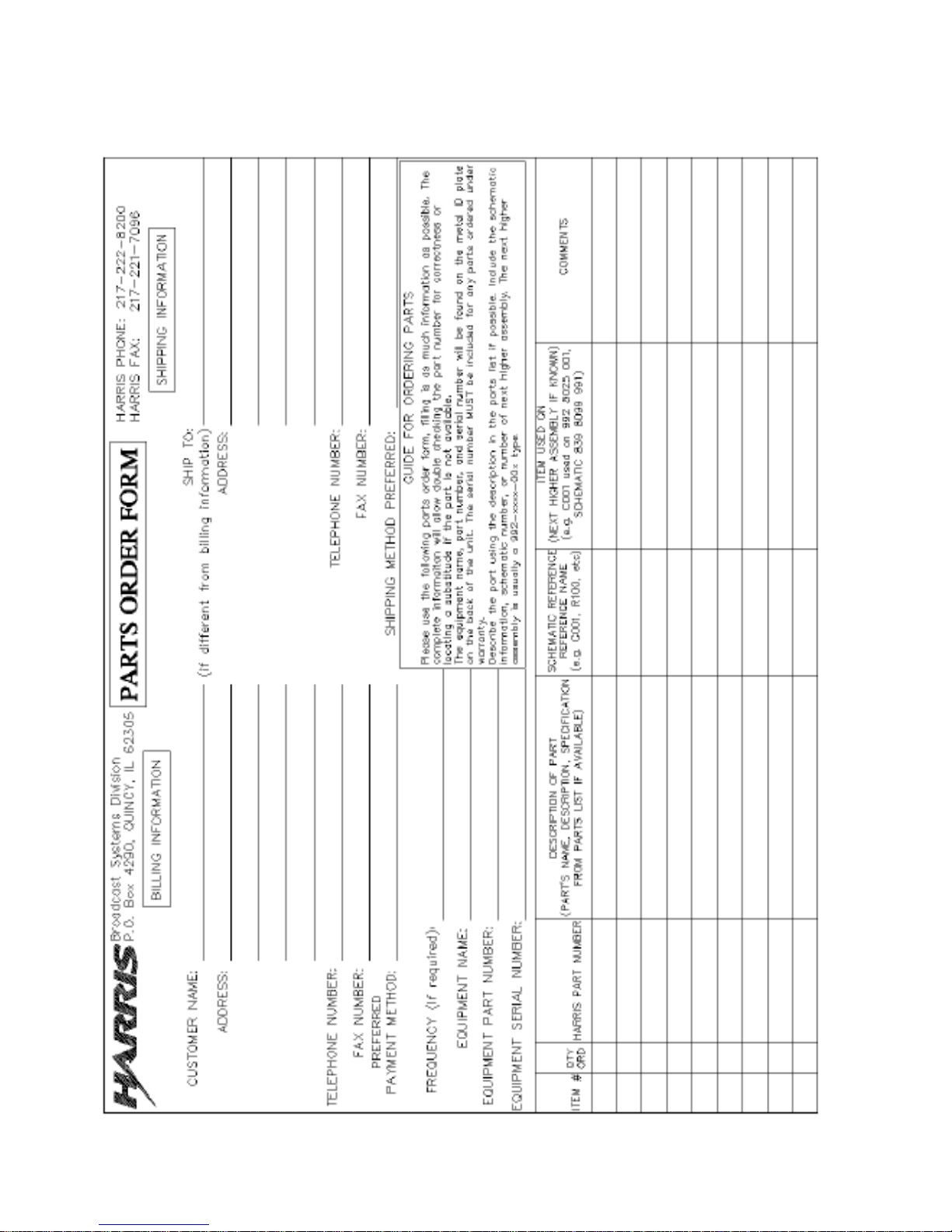
Replaceable Parts Service
Replacement parts are available 24 hours a day, seven days a week from the
HARRIS Service Parts Department. Telephone 217/222-8200 to contact the service
parts department or address correspondence to Service Parts Department, HARRIS
CORPORATION, Broadcast Systems Division, P.O. Box 4290, Quincy, Illinois
62305-4290, USA. The HARRIS factory may also be contacted through a FAX
facility (217/221-7096).
NOTE:
The # symbol used in the parts list means used with (e.g. #C001 = used with C001).
2
WARNING: Disconnect and lockout AC primary power prior to servicing
888-9058-001
Page 3

______________________________________________HARRIS
Manual Revision History
Platinum-i Series Intelligent Transmitter™ Technical Manual
Rev Date ECN Description
A 22Apr2010 P43417 Released
B 20May2010 P47546 Revised Title Page, MRH, and Step-2 on Page-90
Guide to Using Harris Parts List Information
WARNING: Disconnect and lockout AC primary power prior to servicing
888-9058-001
3
Page 4
______________________________________________HARRIS
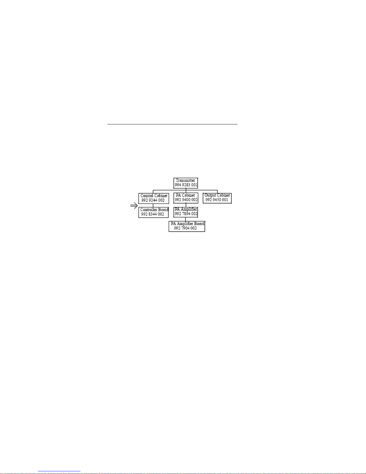
The Harris Replaceable Parts List Index portrays a tree structure with the major items being leftmost in the index. The
example below shows the Transmitter as the highest item in the tree structure. If you were to look at the bill of materials table
for the Transmitter you would find the Control Cabinet, the PA Cabinet, and the Output Cabinet. In the Replaceable Parts
List Index the Control Cabinet, PA Cabinet, and Output Cabinet show up one indentation level below the Transmitter and
implies that they are used in the Transmitter. The Controller Board is indented one level below the Control Cabinet so it will
show up in the bill of material for the Control Cabinet. The tree structure of this same index is shown to the right of the table
and shows indentation level versus tree structure level.
Example of Replaceable Parts List Index and equivalent tree structure:
Replaceable Parts List Index Part Number Page
Table 7-1. Transmitter 994 9283 001 7-2
Table 7-2. Control Cabinet 992 9244 002 7-3
Table 7-3. Controller Board 992 8344 002 7-6
Table 7-4. PA Cabinet 992 9400 002 7-7
Table 7-5. PA Amplifier 994 7894 002 7-9
Table 7-6. PA Amplifier Board 992 7904 002 7-10
Table 7-7. Output Cabinet 992 9450 001 7-12
The part number of the item is shown to the right of the description as is the page in the manual where the bill for that
part number starts. Inside the actual tables, four main headings are used:
• Table #-#. ITEM NAME - HARRIS PART NUMBER - this line gives the information that corresponds
Replaceable Parts List Index entry;
to the
• HARRIS P/N column gives the ten DIGIT Harris part number (usually in ascending order);
• DESCRIPTION column gives a 25 character or less description of the part number;
• REF. SYMBOLS/EXPLANATIONS column 1) gives the reference designators for the item (i.e., C001,
R102,etc.) that corresponds to the number found in the schematics (C001 in a bill of material is equivalent
to C1 on the schematic) or 2) gives added information or further explanation (i.e., “Used for 208V
operation only,” or “Used for HT 10LS only,” etc.).
Inside the individual tables some standard conventions are used:
• A # symbol in front of a component such as #C001 under the REF. SYMBOLS/EXPLANATIONS
column means that this item is used on or with C001 and is not the actual part number for C001.
• In the ten digit part numbers, if the last three numbers are 000, the item is a part that Harris has
purchased and has not manufactured or modified. If the last three numbers are other than 000, the item is
either manufactured by Harris or is purchased from a vendor and modified for use in the Harris product.
• The first three digits of the ten DIGIT part number tell which family the part number belongs to - for
example, all electrolytic (can) capacitors will be in the same family (524 xxxx 000). If an electrolytic (can)
capacitor is found to have a 9xx xxxx xxx part number (a number outside of the normal family of
numbers), it has probably been modified in some manner at the Harris factory and will therefore show up
farther down into the individual parts
4
WARNING: Disconnect and lockout AC primary power prior to servicing
888-9058-001
Page 5

______________________________________________HARRIS
list (because each table is normally sorted in ascending order). Most Harris made or modified assemblies
will have 9xx xxxx xxx numbers associated with them.
The term “SEE HIGHER LEVEL BILL” in the description column implies that the reference designated
part number will show up in a bill that is higher in the tree structure. This is often the case for components
that may be frequency determinant or voltage determinant and are called out in a higher level bill structure
that is more customer dependent than the bill at a lower level.
WARNING: Disconnect and lockout AC primary power prior to servicing
888-9058-001
5
Page 6
______________________________________________HARRIS
6
WARNING: Disconnect and lockout AC primary power prior to servicing
888-9058-001
Page 7

______________________________________________HARRIS
WARNING:
THE CURRENTS AND VOLTAGES IN THIS EQUIPMENT ARE DANGEROUS.
PERSONNEL MUST AT ALL TIMES OBSERVE SAFETY WARNINGS, INSTRUCTIONS
AND REGULATIONS.
This manual is intended as a general guide for trained and qualified personnel who are
aware of the dangers inherent in handling potentially hazardous electrical/electronic
circuits. It is not intended to contain a complete statement of all safety precautions which
should be observed by personnel in using this or other electronic equipment.
The installation, operation, maintenance and service of this equipment involves risks both
to personnel and equipment, and must be performed only by qualified personnel
exercising due care.
HARRIS CORPORATION shall not be responsible for injury or damage resulting from
improper procedures or from the use of improperly trained or inexperienced personnel
performing such tasks. During installation and operation of this equipment, local building
codes and fire protection standards must be observed.
The following National Fire Protection Association (NFPA) standards are recommended
as reference:
- Automatic Fire Detectors, No. 72E
- Installation, Maintenance, and Use of Portable Fire Extinguishers, No. 10
- Halogenated Fire Extinguishing Agent Systems, No. 12A
WARNING:
ALWAYS DISCONNECT POWER BEFORE OPENING COVERS, DOORS,
ENCLOSURES, GATES, PANELS OR SHIELDS. ALWAYS USE GROUNDING STICKS
AND SHORT OUT HIGH VOLTAGE POINTS BEFORE SERVICING. NEVER MAKE
INTERNAL ADJUSTMENTS, PERFORM MAINTENANCE OR SERVICE WHEN ALONE
OR WHEN FATIGUED.
Do not remove, short-circuit or tamper with interlock switches on access covers, doors,
enclosures, gates, panels or shields. Keep away from live circuits, know your equipment
and don’t take chances.
WARNING:
IN CASE OF EMERGENCY ENSURE THAT POWER HAS BEEN DISCONNECTED.
WARNING:
IF OIL FILLED OR ELECTROLYTIC CAPACITORS ARE UTILIZED IN YOUR
EQUIPMENT, AND IF A LEAK OR BULGE IS APPARENT ON THE CAPACITOR CASE
WHEN THE UNIT IS OPENED FOR SERVICE OR MAINTENANCE, ALLOW THE UNIT
TO COOL DOWN BEFORE ATTEMPTING TO REMOVE THE DEFECTIVE
CAPACITOR. DO NOT ATTEMPT TO SERVICE A DEFECTIVE CAPACITOR WHILE IT
IS HOT DUE TO THE POSSIBILITY OF A CASE RUPTURE AND SUBSEQUENT
INJURY.
WARNING: Disconnect and lockout AC primary power prior to servicing
888-9058-001
7
Page 8

______________________________________________HARRIS
Table of Contents
Platinum-i Series Analog
Transmitter
Section 1
Introduction
Introduction....................13
Transmitter Configurations......13
Organization of Transmitter Doc.14
GeneralDescription..............15
AC Power Distribution...........16
Transmitter Control System......17
Main Controller.................17
PA Cabinet Slave Controllers....17
Control Cabinet.................18
Control System Block Diagram....19
50 Volt Power Supply............20
RF Amplifier Modules............20
Power Amplifier Modules.........20
Driver Modules..................20
Visual Signal Flow Path.........20
Exciter.........................20
Transmitter AGC Module..........21
Phase and Gain Module...........21
Visual RF Chains................21
Aural Signal Path...............23
Exciter.........................23
Dual Carrier Systems............23
AGC Module......................23
Phase and Gain..................24
Aural RF Amplifier Chains.......24
Transmitter Output Networks.....25
Transmitter System Theory.......25
Control System..................25
Main Controller Board...........26
PA Cabinet Slave Controller ....26
Module Controller...............26
Control Cabinet.................26
Exciter Switcher................26
Transmitter AGC Module..........26
Phase and Gain..................26
Signal Interface................27
RF PA Cabinets..................27
50 Volt Power Supply............27
RF Output Systems...............27
Platinum RF Combining para......28
Percent of Cabinet Power 3 Cab..28
Percent of Cabinet Power 4 Cab..29
Specifications..................30
Section 2
Installation
Introduction....................33
Installation Planning...........33
Space Requirements..............35
Weights.........................35
RF System Layout................35
Air System......................36
Outside Air Cooling.............36
Air Conditioning................37
Electrical Power................37
Circuit Breaker Selection.......37
Isolation Transformer...........38
Unpacking and EquipmentInvent...38
Equipment Required for Unload...38
Inventory and Inspection........39
Packing Check List..............39
Factory Test Data Sheets........39
Cabinet Placement and Leveling..40
Grounding.......................40
Tap Transformers................41
Installation of 50 Volt Supp....41
RF Output Coax..................41
AC Primary Wiring...............42
UPS Installation................42
Inter-cabinet Wiring............42
Input Signal Wiring.............43
Interlocks and Interfaces.......43
External Interlock: TB1-1, 2....43
Fail-safe Interlock: TB1-3, 4...43
Individual PA Cab External Int..44
External Blower Control.........44
RF Samples......................44
Remote Control I/O..............45
Command In......................45
J31 COMMAND INPUTS..............45
Command Functions...............46
J32: Status Outputs.............46
Status Functions................47
J33: Analog Outputs.............48
J33 Calibrated Outputs Range....48
Optional Remote Status..........48
8
WARNING: Disconnect and lockout AC primary power prior to servicing
888-9058-001
Page 9

______________________________________________HARRIS
Table of Contents (continued)
J34 Optional Status...............49
Transmitter Check Out.............49
Control Cabinet Pre-Operational...49
3 Phase AC and Logic SupplyCheck..49
GUI Setup.........................50
PA Cabinet Checkout...............51
Module Installation...............53
Control System Check Out..........53
Initial Applctn RF Visual Power...54
InitialApplctn RF Aural Power.....55
Power Calibration.................57
Basics of Power Calibration.......57
Visual Power Calibration..........57
PA Cabinet Power Calibration......58
Two Cabinet Reject Load...........58
Three and Four Cabinet Calibra....58
Aural Power Calibration...........59
System Forward Power..............59
Reflected Power...................59
PA Cabinet Power Calibration......59
Two Cabinet Reject Load...........59
Three and Four Cabinet Calibra....60
Visual VSWR Calibration...........60
Aural VSWR Calibration............61
Power Limit.......................62
Section 3
Software Installation/Setup
Re Introduction...................63
eCDi™ and the Platinum-i™Trans....63
Hardware..........................64
Features..........................64
Web GUI...........................65
SNMP Agent........................66
Level 1/Level 2 Functionality.....66
Security..........................67
Downloading the Manual............67
Setup.............................68
Detailed Installation Procedures..69
CD-1A Exciter Serial Number Reset.69
eCDi™ Configuration...............70
Troubleshooting Tips..............72
Apply Changes.....................86
Backing Up the Configuration......87
Restoring a Configuration File....87
Reset Computer IP Address.........87
eCDi Software Updates.............88
Updating the eCDi™.............88
Before Starting................88
Main Controller SerialProgram..91
Exciter Switcher...............92
AGC Module.....................93
PA Cabinets....................95
Slave Controller Indicators....95
RF PA Module LED Display.......97
Operation......................98
Turn ON Sequence...............98
Turn OFF Sequence..............98
Power Raise/Lower..............99
AGC Setup......................99
Section 4
Operation
Introduction..................101
Graphical User Interface......101
376 Micro Controller CPLD.....102
Front Control Panel...........103
CONTROL Pushbuttons...........103
STATUS Indicators/Pushbuttons.103
Auxiliary Control Panel.......104
GUI and eCDi Control..........105
A Short Tutorialusing the GUI.107
GUI Display Screen............109
Fault & Event Screen..........109
Fault Alarm Listing...........110
Control Section...............111
Status and Metering Screens...111
Drive Tab.....................111
PA Cabinet Tab................115
Output Tab....................118
P.S. Power Supply Tab.........122
System Tab....................125
GUI Screen Faults Sum List....127
Section 5
Control System Theory
ControlSystemOverall Descrip..129
Transmitter Control System....129
Micro Module..................131
Features of the 376 module....132
CPLD, Complex Prog Logic Dev..132
I/O Expansion.................132
WARNING: Disconnect and lockout AC primary power prior to servicing
888-9058-001
9
Page 10

______________________________________________HARRIS
Table of Contents (continued)
Life Support Backup..............133
Controller Area Network(CAN)Bus..133
Main Controller..................135
Transmitter Control..............135
Graphical User Interface (GUI)...135
Remote Controls..................135
Control Panel & Indicator Dis....135
Introduction.....................137
Modes of Operation...............137
Button Press.....................137
Button / Indicator Lighting......138
Button States....................139
Messages in the LED Display......140
FP Error.........................140
Com Error, Main Controller.......140
Other Indicators.................140
LIfe Support Functionality.......141
Status Indicators................141
Switches.........................141
Test Points......................141
Module Logic.....................142
Main Controller..................142
Platinum-i TV Controller.........142
Micromodule Interface (Sheet 2)..143
Micro Module (Sheet 3)...........143
Development Hrdwr & Bd (Sheet 3).143
RS232, Watch Dog & Fr Pnl(Sht4)..144
Controller Analog Sense (Sht 5)..144
CPLD (Sheet 6)...................144
Cabinet Bus Controller (Sht 7)...145
Transmitter ON/OFF Cntrl (Sht 8).145
Foldback Voltage D /A (Sheet 9)..145
Controller/Exc Swtchr (Sht 10)...145
Line Voltage & AGC Mon(Sht 11)...145
Interlocks (Sheet 12)............146
Peak Detectors (Shts 13 and 14)..146
Fault Detection (Sheet 15).......146
Dual Tran Interface (Sheet 16)...147
Remote Commands Input (Sht 17)...147
Remote Status Out (Shts 18-19)...147
Optional Remote Status (Sht 20)..147
Remote Analog Outputs (Sheet 21).147
DC Distribution..................148
The Slave Controller Descrip.....148
Slave Controller...............148
Sheet 1........................148
Sheet 2........................149
Sheets 3 and 4.................149
Sheet 5........................149
Sheet 6........................150
Sheet 7........................150
Sheet 8........................150
Sheet 9........................150
Graphical User Interface.......150
Section 6
Control Cabinet
Introduction...................151
Control Cabinet Common.........151
Control Interconnects..........152
AC Power Distribution..........152
DC Power Supplies..............152
Diode Oring....................153
Wiring Diagram, Cntrl Cab Dig..153
RF Flow Path...................153
Main Controller................153
Front Panel Switch Unit........153
Display Unit...................154
Accessory Tray.................154
Exciter Switcher (843-5275-211)154
Logic Crd Detailed Ckt Descrip.155
Exciter Switcher Relay Bd Pnl..155
Operational Setup and Adj......155
Troubleshooting................157
AGC............................157
Detailed Circuit Description...157
Operational Setup and Adj......158
Troubleshooting................158
Phase and Gain.................159
Detailed Circuit Description...159
Operational Setup and Adj......161
Troubleshooting................162
UPS Battery Testing............162
10
WARNING: Disconnect and lockout AC primary power prior to servicing
888-9058-001
Page 11

______________________________________________HARRIS
Table of Contents (continued)
Section 7
PA Cabinet
Introduction.....................163
Theory of Operation..............163
AC Power Flow....................163
Fan and air flow monitoring......163
Interlock Circuits...............163
SCR crowbar......................164
Mechanical Shorting Switch.......164
PA Cabinet Control Logic.........164
Analog PA Cabinet RF Config......164
15KW Vision only PA Cabinet......164
Vision Driver & Sound PA Cabinet.165
Comb Sound & Vision 10KW PA Cab..165
Power Divider....................165
PA Output Combiner Network.......166
Gysel Combiner Theory............166
Maintenance and Troubleshooting..168
Cooling System...................168
Air Filter Replacement...........168
Air Switch Adjustment............168
Back Door Fan....................170
Check for Loose Connections......170
Check MOV Boards.................171
Checking Multi PA Cab Intrlcks...171
Cleaning.........................171
RF Trouble Shooting Divider Comb.172
Section 8
RF Amplifier Modules
General Information..............173
Factory Module Repair............173
Local Module Repair..............174
Module Part Numbers..............174
RF Amplifier Modules Theory......175
Driver Module, Lo Band (Band I)..176
Driver Module, Hi Band (Band II).177
PA Module........................178
RF Quarter Modules...............180
Low Band Quarter Module..........180
High Band Quarter Module.........181
Quarter Module Bias..............182
Protection, Cntrl & Monitor......183
Module Status LEDs...............184
Red LED Fault Blink Codes........185
Module Troubleshooting.........186
Platinum Module Test Fix......187
Troubleshooting-Module Swap....189
Troubleshooting Blink Codes....189
Isolating Other Failures.......194
Locating Failed RF FETs........196
DC Resistance Test.............196
Idle Current Test..............196
Parts Replacement Proced.......197
Soldering Precautions..........197
Quarter Module Replacemnt......199
RF FET Replacement.............200
Testing and Replacing Iso Res..204
Pass FET Replacement...........204
Chip Cap Replacement...........205
Test Procedure TV Modules......205
Pre-operational Checks.........205
Initial Power Up...............205
Idle Current Check.............205
Over/Under Voltage Check.......206
RF Testing.....................206
Application of Drive...........207
Gain Check.....................207
ISO Volts Check................208
Overdrive Check................208
VSWR Protection Check..........210
Section 9
50 Volt Supply
Introduction...................213
Theory of Operation............213
Transformer Primary............213
Six Phase SCR Rectification....214
DC Supply Filtering............214
Control Board..................214
Controller Power Supply........215
50 V Supply Regulation Ckt.....215
Fault Protection Circuits......216
GO / NOGO Circuit..............216
Troubleshooting and Maint......217
Over-temp Fault................218
Over-voltage...................219
Over-current...................219
Breaker Trips..................219
Slave Cntrlr PS Fault Indicat..219
Delay Angle Balance Adjust.....220
Vendor Repair..................229
WARNING: Disconnect and lockout AC primary power prior to servicing
888-9058-001
11
Page 12

______________________________________________HARRIS
NOTES:
12
WARNING: Disconnect and lockout AC primary power prior to servicing
888-9058-001
Page 13

______________________________________________HARRIS
Section 1 1
Platinum-i Series Analog
Transmitter Introduction
______________________________________________________________________
1.1 Introduction
This manual is desrcibes the Harris Analog Platinum-i
transmitters which include the following models with their peak sync power ratings.
Larger models are available by request. Each model is rated for 10% aural.
MODEL POWER MODEL POWER
HT15HS/LS 15 KW HT10HSP 10 KW
HT11LSP 11 KW
HT30HS/LS 30 KW HT20HSP 20 KW
HT22LSP 22 KW
HT45HS/LS 45 KW HT30HSP 30 KW
HT33LSP 33 KW
HT60HS/LS 60 KW HT40HSP 40 KW
HT44LSP 44 KW
TM
series of solid state VHF
1.1.1 Transmitter Configurations
The Platinum-i series contains a separate intelligent control cabinet that can be used in
multiple Platinum Analog transmitter configurations.
There are 2 basic PA cabinet configurations: Standard and Parallel Path. In Standard
configuration; a separate PA cabinet houses vision Driver(s), vision Driver PAs, sound
Driver(s), and the sound PAs. This cabinet is often referred to as the Aural/Driver
Cabinet or Sound/Driver Cabinet. In addition to the Aural/Driver Cabinet are 15kW
vision PA building block cabinets. A 30kW system would include 1 Aural/Driver Cabinet
plus two 15kW vision PA cabinets. In Parallel Path configuration there is no separate
Aural/Driver cabinet. Instead, each PA Cabinet contains vision and sound Drivers, vision
Driver PAs plus sound PAs resulting in 10kW building block cabinets. Thus a 20kW
system would have 2 PA cabinets plus the Control Cabinet.
WARNING: Disconnect and lockout AC primary power prior to servicing
888-9058-001
13
Page 14

______________________________________________HARRIS
NOTE:
The HT60HS/LS Standard configuration system uses 2 Aural/Driver cabinets.
1.1.2 Organization of Transmitter Documentation
• The documentation consists of:
a. Platinum-i Analog Technical Manual (this manual)
b. Platinum-i Analog Drawing Package for High Band or for Low Band
c. HX1V Exciter Manual (a separate manual and drawing package).
• Organization of the Technical Manuals
The text part of the manual is divided into the following sections.
Section 1: Introduction
Section 2: Hardware Installation
Section 3: Software Installation and Setup
Section 4: Operation
Section 5: Control System Theory of Operation
Section 6: Control Cabinet
Section 7: PA Cabinet
Section 8: RF Modules
Section 9: 50 Volt Power Supply
Section 10: Parts Listing
There are different drawing packages for low band and high band systems: the drive
chains and modules are different. The drawing packages are organized in sections with
tab separators as follows:
10K SYSTEM or 15K SYSTEM COMMON SUBSYSTEMS
100 HT10H/11LSP i HT15H/LS i 600 Control System
200 HT20H/22LSP i HT30H/LS i 700 Control Cabinet
300 HT30H/33LSP i HT45H/LS i 800 PA Cabinet
400 HT40H/LSP i HT60H/LS i 900 50 Volt Power Supply
500 NOT USED 1000 High Power RF Modules
14
WARNING: Disconnect and lockout AC primary power prior to servicing
888-9058-001
Page 15
______________________________________________HARRIS
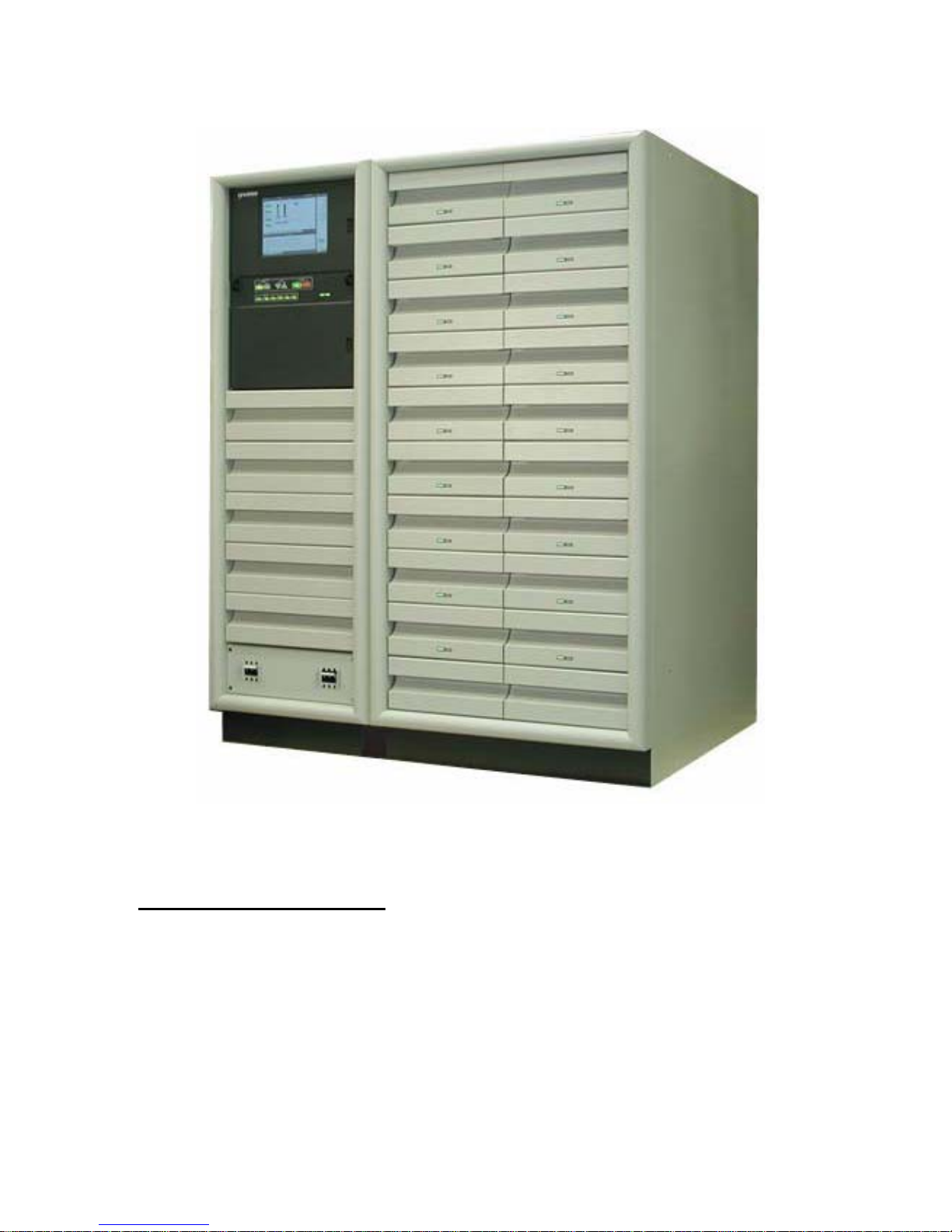
1.2 General Description
The Analog Platinum-i
cabinets (PA). and RF output system. The RF system includes a color notch filter,
harmonic filter and a vision plus sound RF combiner feeding the antenna.
The eCDi version of the control cabinet will be used with new Platinum-i cabinets and
as a retrofit to older PA cabinets. The different versions of the PA cabinet will use
various drive configuration and different modules types.
TM
WARNING: Disconnect and lockout AC primary power prior to servicing
Figure 1- HT10HSi/LSi
consists of a control cabinet, one or more power amplifier
888-9058-001
15
Page 16

______________________________________________HARRIS
Another use will be to retrofit existing analog transmitters to digital service. These
PAs will continue to use the 12 or 17 visual PA module configuration as the digital
power amplifier.
Platinum Series transmitters employ rugged field effect transistors (FETs), parallel
amplifier modules, multiple power supplies, and a high-resolution flat display screen for
monitoring.
The control and monitor system includes storage of fault events with time, date, and
description. VSWR foldback automatically reduces power during high VSWR operation,
such as that encountered with antenna icing.
Available options include dual exciters, an automatic exciter switcher, and redundant
control power supplies.
Each transmitter consists of a control cabinet and one or more amplifier cabinets.
Transmitters from 1-10 kW have a single amplifier cabinet containing the aural path, the
visual drive chain, and the visual final. 20 kW transmitters have two amplifier cabinets like
those used in the 10 kW transmitter.
15 kW transmitters have two amplifier cabinets: one for the aural path and visual drive
chain, and one for the visual final. 30 kW transmitters have one cabinet for aural path and
visual drive chain, and two 15 kW visual final cabinets. 45kWunits have two aural
path/visual drive chain cabinets and three 15 kW visual finals. Finally, 60 kW transmitters
have six cabinets, doubling the 30 kW architecture.
In transmitters with multiple visual amplifier cabinets, outboard hybrids are used to
combine the outputs of the visual finals. Optional notch or hybrid diplexers are available
for all models to combine aural and visual signals to permit using a common antenna
system.
1.2.1 AC Power Distribution
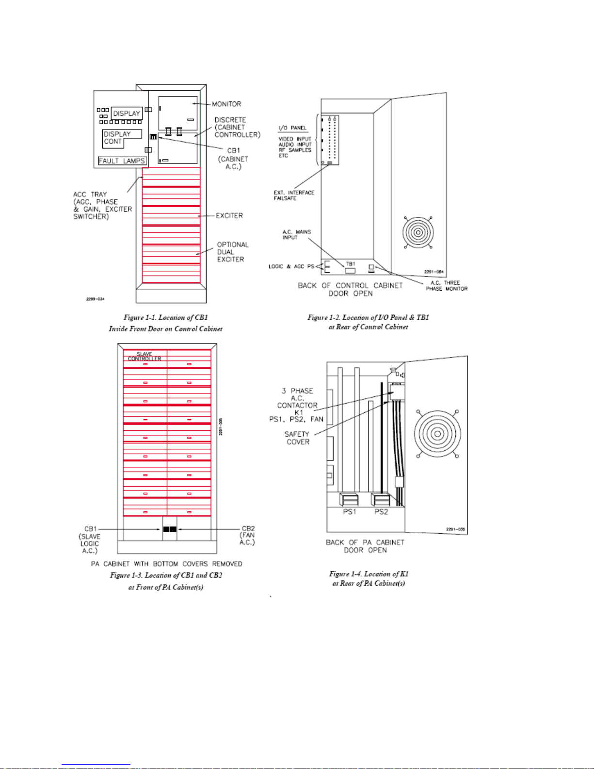
Refer to AC Power Distribution drawing for the following discussion. Each cabinet has its
own AC power source. Control cabinet breaker CB-1, located behind the control panel left
of the controller boards, protects the wiring in the control cabinet (see Figure 1-1). A phase
monitor guards against low voltage, loss of one phase, and reversal of the phase
sequencing. Line voltage samples are provided for the system monitor. All logic supplies,
exciter power and fan in the control cabinet are controlled by CB-1.
Each amplifier cabinet’s AC power is fed through CB-1 to the logic supply (see Figure 1-
3). AC Contactor K-1 feeds the 50 volt supplies and fan breaker CB-2 (see Figure 1- 4).
Aux relay K-2 activates the AC contactor through commands from the slave controller.
16
WARNING: Disconnect and lockout AC primary power prior to servicing
888-9058-001
Page 17

______________________________________________HARRIS
1.2.2 Transmitter Control System
See Figure 1-5. The control system for the transmitter consists of a main controller
mounted in the control cabinet, plus individual slave controllers mounted in each amplifier
cabinet. Data from the system is interfaced through the monitor board to the display
controller, and shown on the front panel flat display screen as bar graphs and numerical
readings. Transmitter ON/OFF, LOCAL/REMOTE, and power RAISE/LOWER switches
are located on the control cabinet, to the right of the display panel.
1.2.3 Display Panel
The main control system samples each cabinet and gathers all of the status and analog data
for the display. The touch screen display is part of a monitoring computer and the main
controller will continue operation of the transmitter when this computer has a fault. The
control panel indicators back up the touch screen and operation button back up the touch
screen button functions.
1.2.4 Main Controller
The transmitter main control unit provides a central point for control and monitoring the
entire system. The main controller interfaces with the slave controller(s) for the amplifier
cabinets’ ON/OFF commands, and with the exciter for power RAISE/LOWER commands.
Peak detectors collect aural and visual RF samples and send them to the main controller for
power metering. The main controller also directs VSWR foldback action.
The main controller has a battery backup to restore the transmitter to its previous operating
condition after a temporary AC power failure. A power down timer will automatically turn
the transmitter off if the power is not restored within approximately two hours. Remote
status and analog outputs are provided by the main controller to a series of D connectors in
the rear of the control cabinet.
1.2.5 Slave Controllers
The slave controllers are mounted in the upper left-hand slot of each amplifier cabinet.
Each is responsible for controlling and monitoring its PA cabinet. The controllers interface
the cabinet to the main controller and monitor in the control cabinet.
WARNING: Disconnect and lockout AC primary power prior to servicing
888-9058-001
17
Page 18
______________________________________________HARRIS
18
WARNING: Disconnect and lockout AC primary power prior to servicing
888-9058-001
Page 19
______________________________________________HARRIS
WARNING: Disconnect and lockout AC primary power prior to servicing
Figure 1-5, Control System Block Diagram
888-9058-001
19
Page 20

______________________________________________HARRIS
Each slave controller controls a cabinet’s fan motor, 50 volt DC supplies, and RF amplifier
modules. Slave controllers also report cabinet door interlock status, air interlock status,
module faults, and power supply faults to the main controller.
Cabinet input drive and RF power output samples, detected by RF peak detectors, are
relayed to the main controller through the slave controllers as well.
In the event of loss of the main controller, each slave may be used to operate its amplifier
cabinet for emergency service.
1.2.7 50 Volt Power Supplies
Each PA cabinet has one or two 50 volt supplies, depending on system configuration.
These supplies convert the AC power to 50 volts DC for the RF amplifier modules. Each is
rated at 300 amps, and regulated to hold the transmitter power stable despite power line
voltage changes. Internal fault protection is interfaced to the slave controller.
1.2.8 RF Amplifier Modules
Only two types of RF amplifier modules are used in the aural and visual chains of any
given Platinum transmitter system:
1.2.8.1 Power Amplifiers (PAs)
PAs are used primarily as final amplifiers. Each is capable of supplying 1,050 watts RF
output, either aural CW or visual peak sync. PAs are also used as inter-stage amplifiers in
larger visual cabinets, to drive several subsequent parallel PA modules. PAs are singlestage amplifiers, consisting of paralleled class AB amplifiers.
1.2.8.2 Driver Modules
Driver modules provide high gain. Primarily used in preamp applications to drive PAs, they
are also used as aural final amplifiers in low power applications. Driver modules are keyed
so that they cannot be plugged into a PA slot.
Low band drivers contain two cascaded class A stages. High band drivers contain two class
A stages and one class AB stage. In both cases, the final stage in a driver consists of two
paralleled amplifier blocks.
1.2.9 Visual Signal Flow Path
A basic visual signal flow topology is common to all Platinum Series transmitters. For the
following discussion, refer to the transmitter block diagram in the drawing package.
1.2.9.1 Exciter
Video is applied to the exciter where it is clamped, pre-corrected for differential gain and
differential phase, and modulated onto the IF carrier (37 MHz for system M/NTSC,
38.9MHz for B/PAL). Next, frequency response and group delay are corrected. Vestigial
sideband filtering follows. The IF signal then passes through an AGC amplifier to
correctors for linearity and ICPM. A local oscillator and mixer in the exciter upconvert the
20
WARNING: Disconnect and lockout AC primary power prior to servicing
888-9058-001
Page 21

______________________________________________HARRIS
IF signal to the transmit frequency, and the resulting signal is bandpass filtered and
amplified. The exciter’s final amplifier is capable of supplying up to 1 watt peak sync to
subsequent stages, and a sample of its output is routed to the exciter’s AGC circuit to hold
the exciter’s power output constant.
If optional dual exciters and an exciter switcher are used, both exciters are fed a video
signal, and each exciter’s visual output feeds the switcher.
1.2.9.2 Transmitter AGC Module
The exciter switcher output (or single exciter output) then passes to the transmitter AGC
module whose job is to maintain a constant gain loop by monitoring a sample of transmitter
visual output and correspondingly controlling exciter drive.
1.2.9.3 Phase and Gain Module
In transmitters with multiple visual PA cabinets, the AGC module passes the RF signal to
one or more phase and gain modules. Each phase and gain module splits the drive into two
parts whose relative amplitude and phase are adjustable. This allows trimming to
compensate for small gain and phase differences between cabinets, to insure the cabinet
outputs maintain the proper phase and amplitude relationships when passed to the final
hybrid Combiner(s).
The number of phase and gain modules used depends on the number of visual PA cabinets.
In transmitters with a single visual PA cabinet (15 kW and below), no phase and gain
modules are
necessary. The output of the AGC module passes directly to the RF chain.
Since phase and gain modules introduce loss into the system, additional preamps are
sometimes necessary. The locations of phase and gain modules and preamps, vary by
configuration. For details, see the descriptions in the following section on visual the
RF chain configurations.
1.2.9.4 Visual RF Amplifier Chains
The Visual RF amplifier chains in the various models vary in complexity from as few as
two amplifier modules to over sixty. Following are synopses of the various combinations:
10 kW HT10HSP and the HT11LSP which is 11kW, Parallel Path,
The AGC output feeds a driver module, whose output passes through a PA module. In
a 10 kW and 11kW transmitters, a 12-way divider feeds 12 PA modules.
The PA outputs are recombined in a six-way (5 kW) or twelve-way (10 kW)
combiner, whose output becomes the cabinet’s visual output.
In a 20 kW system (also 22kW Low band), the AGC module feeds a phase and gain
module, whose outputs feed two 10 kW (11kW) visual cabinets like those described
above. A 3 dB quadrature hybrid then combines the two cabinet outputs.
WARNING: Disconnect and lockout AC primary power prior to servicing
888-9058-001
21
Page 22

______________________________________________HARRIS
15 kW (Standard)
In a 15 kW system, the AGC module’s output feeds a driver module, which drives a
PA module. In a low band transmitter, the PA’s output is split in a 16-way divider,
whose outputs feed 16 PA modules. The outputs are recombined in a 16-way
combiner, whose output becomes the cabinet’s visual output.
In high band transmitters, the same principle applies, except that 17 PA modules and
17-way dividers and combiners are used.
The 30, 45, and 60 kW transmitter visual chains are multiples of this basic 15 kW
architecture.
30 kW (Standard)
In a 30 kW transmitter, the AGC output passes through a phase and gain module. In
high band systems, the two outputs are sent to two preamps. In low band systems, the
preamps are not necessary.
The resulting outputs are sent to two 15 kW visual cabinets (see 15 kW system,
above). The cabinet outputs are combined with a 3 dB quadrature hybrid combiner.
45 kW (Standard)
In a 45 kW system, one phase and gain module feeds one visual cabinet and a
preamp, whose output feeds a second phase and gain module. Three outputs are thus
obtained. In high band systems, a preamp is inserted in each path at this point, and
the three outputs pass to the aural PA and visual driver cabinet. In low band systems,
these three preamps are omitted.
The three outputs are each fed to driver modules. In low band systems, the driver
outputs are each passed to one of three PA modules, whose outputs each drive a 15
kW visual PA cabinet (see 15 kW system, above).
In high band systems, each of the three drivers supplies input to a pair of PA
modules. The PAs are paralleled into pairs using two-way power dividers and
combiners. The three outputs then pass to three 15 kW visual cabinets (see 15 kW
system, above).
At the outputs of the three visual PA cabinets, a 3 dB hybrid combines the first two
visual cabinet outputs, which combine with the third in a 4.77/1.76 dB asymmetrical
hybrid combiner. The combined output passes through a harmonic and color notch
filter on its way to the optional diplexer.
60 kW (Standard)
The AGC module output feeds a phase and gain module, whose outputs feed two
more phase and gain modules.
22
WARNING: Disconnect and lockout AC primary power prior to servicing
888-9058-001
Page 23

______________________________________________HARRIS
In low band systems, the four outputs are sent to four driver modules, which in turn
are used to drive four PA modules. These four outputs drive four 15 kW visual PA
cabinets (see 15 kW system, above).
In high band transmitters, the four phase and gain module outputs to four driver
modules. Each driver module output is split using a two-way divider, whose outputs
each drive a PA module. The PA module outputs are recombined using four two-way
combiners, before passing to the four 15 kW PA cabinets (see 15 kW system, above).
The visual cabinet outputs are recombined in pairs, using two 3 dB quadrature
hybrids. Finally, the pairs are recombined with a final 3 dB hybrid.
1.2.10 Aural Signal Path
Again, the basic topologies of the aural paths in the various models are similar. As in the
visual path, the exciter aural output passes to an AGC module which monitors a sample of
the aural System output. The AGC module output then drives the aural RF chain. (Refer to
the transmitter block diagram in the drawing package for this discussion.)
1.2.10.1 Exciter
Either monaural audio and SCA, or externally generated composite stereo, is fed to the
exciter and modulated onto an IF frequency, which is lower than that of the visual IF by an
amount equal to the difference between the desired aural and visual carriers. The modulator
is a voltage-controlled oscillator whose center frequency is held constant by a phase-locked
loop (PLL).
IF group delay correction (optional) can be used at this point to improve stereo separation
in systems where notch diplexers are used. The IF signal is converted up to channel using a
mixer and the same LO as in the visual chain. The resulting signal is bandpass filtered and
amplified, becoming the exciter’s aural output. As in the visual path, if dual exciters
(optional) are used, each exciter’s aural output is routed to the exciter switcher.
1.2.10.2 Dual-Carrier Systems
In systems where dual aural carriers are generated, the exciter path takes a different form.
The two signals are modulated onto two different IF carriers, and the modulated carriers are
added together. Linearity pre-correction is added to prevent intermodulation of the two
carriers. The resulting signal is mixed up to channel with the same LO as used in the visual
chain, and is bandpass filtered and amplified, becoming the exciter output.
1.2.10.3 AGC Module
As in the visual path, the exciter switcher output or single exciter feeds an AGC module,
which holds the aural transmitter gain constant by controlling aural RF drive based on
samples of exciter drive and transmitter aural output.
1.2.10.4 Phase and Gain Module
WARNING: Disconnect and lockout AC primary power prior to servicing
888-9058-001
23
Page 24

______________________________________________HARRIS
As in the visual signal path, in higher-powered systems, it may become necessary to feed
parallel signal paths through one or more phase and gain modules. These modules allow the
gain and phase of each path to be trimmed, so that the proper phase and amplitude
relationships are obtained at the final combiner input.
1.2.10.5 Aural RF Amplifier Chains
The aural RF amplifier chains vary in complexity depending on visual peak power output,
10% or 20% aural power, and single or parallel paths. The following configurations are
used in the various transmitter models:
10 kW and 15 kW Systems, 10% Aural (normal sound power)
In these systems, the aural AGC output feeds a driver module, whose output is split in
a two-way splitter and sent to two PA modules. The PA module outputs are
recombined in a two-way combiner, whose output passes through a harmonic filter
before reaching the optional notch or hybrid diplexer.
The drive signal is then split four ways in a four-way splitter, whose outputs drive
four parallel PA modules. The outputs are recombined in a four-way combiner and
passed through a harmonic filter before being sent to the optional diplexer.
20 kW Systems, 10% Aural (normal)
The aural AGC module output passes through a phase and gain module. Each of the
two outputs passes to an aural chain in one of the PA cabinets.
Once inside the PA cabinets, the two signals are sent to driver modules. Their outputs
are split using two-way dividers, and the resulting outputs feed an array of four PA
modules. The two PAs in each cabinet feed two-way combiners, and the combiner
outputs feed a 3 dB hybrid used as a final two-way combiner. The resulting signal
passes through a harmonic filter before being sent to the optional diplexer.
30 kW Systems, 10% Aural (normal)
In a high band system, the AGC module output first passes through a preamp. In lowband systems, the preamp is not necessary.
The resulting output drives a driver module. The driver output is divided in a fourway divider, and fed to four parallel PA modules. The outputs are recombined in a
four-way combiner, whose output passes through a harmonic filter on its way to the
optional diplexer.
45 kW Systems, 10% Aural (normal)
In a 45 kW low band system, the AGC module output drives a phase and gain
module, whose outputs drive two driver modules. In high band systems, the two
signals each pass through three-way power dividers, whose outputs feed a total of six
aural PA modules. The PA module outputs are recombined using three-way
combiners and a 3 dB quadrature hybrid, whose output passes through a harmonic
filter to the optional diplexer.
24
WARNING: Disconnect and lockout AC primary power prior to servicing
888-9058-001
Page 25

______________________________________________HARRIS
60 kW Systems, 10% Aural (standard)
The AGC module output feeds a phase and gain module. In high band systems, the
two outputs are then fed to two preamps. In low band transmitters, the preamps are
not necessary.
Each of the two outputs feeds a driver module. The driver outputs are each split in
four-way dividers, for a total of eight outputs, and the outputs drive an array of eight
PA modules. The PA outputs pass to four-way power combiners, whose outputs are
combined in a 3 dB quadrature hybrid used as a two-way combiner. The combined
output passes through a harmonic filter before being sent to the optional diplexer.
1.2.11 Transmitter Output Networks
The transmitter output network performs three functions: filtering harmonics from the
outputs, removing color subcarrier remnants from the vestigial sideband, and combining
the aural and visual outputs into a common antenna feed for transmission. Two common
configurations exist:
10 kW Systems
A combination color notch filter/notch diplexer (optional) receives the aural and
visual outputs and combines them. The output then passes through a harmonic filter
to the antenna system.
15-60 kW Systems
Two harmonic filters are used: one in the visual path, and one in the aural path. The
output of the visual harmonic filter feeds a color notch filter. The outputs of the aural
harmonic and visual color notch filters feed a notch diplexer (optional),whose output
passes to the antenna system.
1.3 Transmitter System Theory of Operation
1.3.1 Control System
The transmitter uses a distributed architecture control system . This means that some
transmitter sub-systems include self monitoring and protection and report to the Main
Controller for display on the GUI (Graphical User Interface) and to a remote interface.
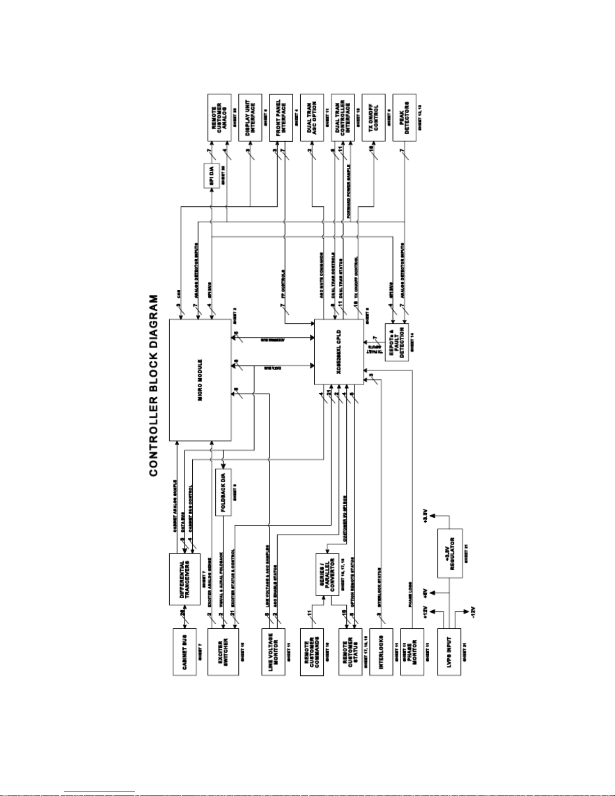
The heart of the system is the 376 Micro Module and the XC95288XL CPLD which is
used for control and monitoring interface.
1.3.1.1 Main Controller Board
This board is responsible for transmitter control and monitoring. The Main Controller is
responsible for system level control (multiple sub-systems) since it is the only part of the
control system which can monitor the entire transmitter. This printed wiring board is
mounted just below the top of the cabinet and also serves as the customer and system Input
WARNING: Disconnect and lockout AC primary power prior to servicing
888-9058-001
25
Page 26

______________________________________________HARRIS
and Output, I/O. It gathers status and fault data from the individual sub-systems and reports
that information to the operator locally and by remote control.
1.3.1.2 PA Cabinet Slave Controller
This board interfaces with the module and power supply controller boards to transfer
information to the main controller. It also has control functions related to that PA
cabinet. Refer to paragraph 1.2.6.
1.3.1.3 RF Module Controller
A logic and control board responsible for protection and control of the one RF Driver or
PA Module that it is part of.
1.3.1.4 50 RF Module Power Supply Controller Board
Responsible for control and monitoring of the 50V RF amplifier power supplies.
1.3.2 Control Cabinet.
The control cabinet contains a digital exciter, and an optional second Exciter. The RF
signal path includes an optional exciter switcher, automatic gain control module and phase
and gain modules when more than one PA cabinet is used. The main controller and the GUI
are part of the control cabinet. The RF drive levels to the PA cabinet input(s) are in the 25
to 100mW range.
1.3.2.1 Exciter Switcher
If optional dual exciters and an Exciter switcher are used, both exciters are fed video and
the appropriate sound signals. Each Exciter's RF output feeds a logic controlled coax
switch. The selected Exciter signal in a single PA cabinet system then goes to the AGC.
When more than one
PA cabinet is used the AGC output is connected to one or more Phase and Gain units.
1.3.2.2 Transmitter AGC Module
The single Exciter output/exciter switcher output to the transmitter AGC module, whose
job is to maintain a constant drive level by monitoring a sample of transmitter output, and
correspondingly controlling PA cabinet input drive.
1.3.2.3 Phase and Gain
In transmitters with multiple PA cabinets, the AGC module is followed by one or more
phase and gain modules. Each phase and gain module splits the drive into two signals
whose relative amplitude and phase are adjustable. This allows trimming to compensate for
small gain and phase differences between cabinets, so that the PA cabinet outputs maintain
the proper phase and amplitude relationships when combined in the following 3 dB or 4.77
dB hybrid combiner(s). Phase and Gain units are adjusted for minimum hybrid reject load
power.
26
WARNING: Disconnect and lockout AC primary power prior to servicing
888-9058-001
Page 27

______________________________________________HARRIS
1.3.3 Signal Interface
Signal interface for signal input and monitoring by remote control is located on top of
the control cabinet. The PA cabinet top is used for the control and monitoring cable
interconnect with the PA cabinet(s) and the monitor sample cables.
1.3.4 RF PA Cabinets
The PA cabinets have independent:
• AC power feed from a circuit breaker.
• Cabinet level control system
• Cooling system, fan and interlock pressure switch
• Logic power supply
• 50 Volt RF module supplies with control logic
• Rear Door interlock
• Cabinet external interlock to protect combining hybrid reject loads. Maintenance can be
performed on one PA cabinet while the others are operating. A block diagram documents
each transmitter configuration in the appropriate drawing package system, sections
through 5.
Refer to paragraph 1.2.9.4 for individual cabinet configurations.
1.3.5 50 Volt Power Supply
These regulated supplies convert the AC power to 50 volts DC for the RF amplifier
modules. Each is rated at 300 amps, and designed to accommodate -10% to +20%
power line voltage changes. Internal supply fault protection is interfaced to the slave
controller.
The PTCD5P1i has one supply. Larger PA cabinets have two 50 volt power supplies.
The supply uses SCRs for voltage regulation. When two power supplies are used, one
supply will be connected as a delta load, the other as a wye load to reduce supply
induced AC mains harmonics. Each supply also has a tuned power line harmonic filter.
This is tuned near the 5 harmonic to reduce a possible motor damaging harmonic.
Single cabinet PAs may have optional internal diode ORing to power driver modules
from either supply.
The 50 Volt supply is covered in detail in this manual section 9.
1.3.6 RF Output Systems
The transmitter output network has several functions, depending on the system, including
combining RF amplifiers, removing out-of-band signals, and filtering harmonics from the
outputs. The sharp tuned (Cool Fuel) filter together with the Apex exciter allow higher
WARNING: Disconnect and lockout AC primary power prior to servicing
888-9058-001
27
Page 28

______________________________________________HARRIS
average power levels while maintaining out of band emission specifications by filtering
IMD product near the mask filter shoulder. Some RF systems contain channel combiners,
allowing two or more channels to share the same transmission line and antenna.
Directional coupler units develop RF samples for metering RF power levels and are used as
feedback samples for the exciter real time correction circuits. The IPA sample inputs on the
Apex exciter are not used, therefore the Apex exciter IPA mode should be set to bypass.
The Platinum transmitter system interconnect drawings detail these RF sample connections.
The combining of transmitters on different frequencies often require special attention to
the sample lines for exciter correction and VSWR monitoring. The sample lines may
require filtering and phasing networks to remove unwanted frequencies in the RF samples.
This is critical for RTAC samples.
1.4 Platinum RF Combining Parameters
1.4.1.01 Two PA Cabinets
The parameters for the two cabinet system are easy to determine by applying the hybrid
rules for division and combining to determine how to calibrate the cabinet power levels
and the reject load wattage. When one cabinet does not put out power, the other cabinet
will deliver half of its output power to the antenna, the other half to the reject load. The
cabinet output power is calibrated in watts and the reject power in percentage of the
loads rating.
Example:
Total power out (TPO) is 7.4 KW, each cabinets output is 3.7 KW (ignoring losses) and
cabinet half power would be 1.85 KW. The reject load is rated at 2.5 KW, the power
calibration in this case would be 1.85 / 2.5 or 74 percent.
1.4.0.2 Percent of Cabinet Power With Three PA Cabinets
CABINET CABINET CABINET A/B AB/C COMBINED
A B C REJECT REJECT OUTPUT
100 0 0 50 16.6 33.3
0 100 0 50 16.6 33.3
0 0 100 0 66.6 33.3
100 100 0 0 66.6 133.3
100 0 100 50 16.6 133.3
100 100 100 0 0 300
28
WARNING: Disconnect and lockout AC primary power prior to servicing
888-9058-001
Page 29

______________________________________________HARRIS
1.4.0.3 Percent of Power With Four PA Cabinets
CABINETS A/B CABINETS C/D AB/CD COMBINED
A & B REJECT C & D REJECT REJECT OUTPUT
ONE 50 BOTH 0 25 225
BOTH 0 ONE 50 25 225
BOTH 0 NONE 0 100 100
ONE 50 ONE 50 0 100
BOTH 0 BOTH 0 0 400
This information can be used to calibrate the power metering for the cabinet and reject
loads. This is assuming the phase and gain controls have minimized the amount of
reject power and the cabinets output powers are about the same.
1.4.0.4 Drive Power Meter Calibration
The drive levels can be calibrated using the drive directional coupler element. The
Agilent power meter has a offset feature, enter the coupling ratio from the element as
the offset. The power meter now reads the power direct. This procedure can also be
used as an alternative to calibrate the cabinet power out and reject load power.
WARNING: Disconnect and lockout AC primary power prior to servicing
888-9058-001
29
Page 30

______________________________________________HARRIS
1.3 Specifications
30
WARNING: Disconnect and lockout AC primary power prior to servicing
888-9058-001
Page 31

______________________________________________HARRIS
WARNING: Disconnect and lockout AC primary power prior to servicing
888-9058-001
31
Page 32

______________________________________________HARRIS
32
WARNING: Disconnect and lockout AC primary power prior to servicing
888-9058-001
Page 33

______________________________________________HARRIS
Section 2 2
Platinum-i Series Analog
Transmitter Installation
____________________________________________________________________________
2.1 Introduction
This section contains information necessary to install and to perform initial checkout
procedures on Platinum-i Series television transmitters. The drawing package will
contain drawings referred to in section 2, use the first page Cover Sheet to locate the
drawings.
2.2 Installation Planning
The information in this section is intended to be used only as a general guideline in
planning installation. Since all installations differ in some respects, and in order to
conform to local building and electrical codes, the information contained herein must
be adapted for each particular installation.
Planning and preparation are the most important factors in a successful, efficient, and
safe installation phase of a new transmitter. Study equipment manuals beforehand and
become thoroughly familiar with the installation requirements for each piece of
equipment.
The transmitter equipment installation phases should be planned carefully before the
equipment arrives and a detailed plan worked out and written down. Know what
installation equipment and materials Harris is supplying with the transmitter and what
equipment and materials the station must supply. In general, a transmitter installation
requires that the following areas be addressed:
a. Have a clear plan for transmitter system monitoring and make provision for any
needed RF monitoring samples. Make sure the monitoring equipment will be
suitably located for convenient operation and monitoring. STL and remote control
equipment should also be planned early. While not part of the transmitter,
monitoring and control equipment (and the STL) must be available when installation
is completed to test the transmitter and to put it into service.
b. Plan a star point grounding system for the building and equipment cabinets. This
grounding system should incorporate the grounding system for the AC service
entrance and the grounding system for the tower.
WARNING: Disconnect and lockout AC primary power prior to servicing
888-9058-001
33
Page 34

______________________________________________HARRIS
c. When considering the sequence of events during an installation, it is important to
approach the transmitter, its peripherals, and the building as a system . “typical”
drawings are used as references. It must be assumed special requirements will
cause deviations from the published installation drawings in order to accommodate
a particular configuration or building requirement.
d. In a new installation, interior walls should be in place, ceiling work should be
complete, concrete floors should be aged and well sealed, and all painting be
completed before arrival of the equipment or the transmitter is placed in the
room. Transmitters and other electronic equipment can be damaged or made
inoperable by dust and dirt entering the equipment. Even a plastic covering
placed over the transmitter rarely keeps out concrete dust and plaster dust created
from drywall installation.
e. In a new installation, will electrical power be available when needed? Often
transmitter installation and checkout is held up because primary power is not
available.
f. In an existing facility, must an existing transmitter remain on the air during
installation of the new equipment? Plan how this is to be done to minimize off-air time.
g. A staging area should be chosen and set aside to place the boxes and crates that
contain all the smaller parts and assemblies not shipped attached to the transmitter.
A separate area should be used to stage all installation materials (plumbing
materials, wire, conduit and accessories, loose hardware, etc.)
h. Each piece of equipment should be inspected for shipping damage. Inventory all
equipment and the contents of each box and compare to the packing check list
that comes with the equipment.
i. Think about how the equipment will be unloaded. Will the proper lifting and
moving equipment be there when the truck containing the transmitter arrives?
Will there be enough workers there to help?
j. Equipment placement must be worked out carefully. Use a station layout drawing
to determine equipment placement and the order in which the equipment should
be set in place. If possible, lay out equipment location with lines marked on the
floor.
k. When planning placement of the output RF system, make certain the ceiling or
overhead framing will support the weight of the RF components. If not, structure
modification or floor-mounted components may be required.
34
WARNING: Disconnect and lockout AC primary power prior to servicing
888-9058-001
Page 35

______________________________________________HARRIS
l. The electrical and RF plumbing work should begin at the start of the installation
in order not to delay completion, however the transmitter, RF output system and
cooling system plumbing should be installed prior to running electrical conduits
or air handling ducts in the transmitter space. This will prevent interference issues
between RF lines and electrical conduit and cooling ductwork.
m. Hanging hardware must be on-hand to avoid delays. Ensure that all pipe hangers,
conduit hangers, threaded rod, beam clamps, Unistrut and Unistrut hardware are
on site.
Ensure that all necessary tools are on site and in good shape when needed. Check
transmitter and other equipment technical manuals to see if any specialized tools are
required. Make arrangements to obtain them if necessary.
2.2.0.1 Space Requirements
(Refer to Transmitter Outline drawings.)
To allow for servicing the transmitter, a minimum clearance of 4 feet in front of and 5
feet behind the cabinets is recommended. Minimum clearances are shown in the
drawings.
Planning for the transmitter room should allow space for program input, monitoring,
remote control, and test equipment as well as the transmitter. Additional area may also
be required for tower lighting, HVAC equipment, storage, and a workbench.
2.2.1 Weights
Weights are listed below each cabinet on the Transmitter Outline drawing. Be sure to
include this information in your planning for the building and verify that the structure is
capable of safely supporting the total weight of the transmitter and its peripheral
equipment. The 50 Volt power supplies are furnished with two metal wheels for easy
movement and installation in the transmitter.
Consider the type of floor on which the power supply will rest. The weight is carried on
two wheels, which will possibly mar the floor. Long term weight may damage the floor,
making power supply removal for maintenance very difficult. Protection of tiled floors
should be considered.
2.2.2 RF System Layout
Refer to the RF Layout drawing for the transmitter and RF system floor plan. A system
of overhead supports and hangers is needed to support the coaxial lines, filters, and
other RF components. The support system should be installed so that the RF
components are completely supported by the hangers, to minimize the weight carried
by the output connectors at the top of the cabinets.
888-9058-001
WARNING: Disconnect and lockout AC primary power prior to servicing
35
Page 36

______________________________________________HARRIS
n. An overhead grid of Unistrut™ or angle iron and 3/8 inch threaded rod is most
commonly used. Pipe hangers for steam pipe may be used to hold the coax, combiners,
etc. Pay special attention to the different types of materials being used. For example, if
galvanized parts are used to support copper RF plumbing, the two must be separated
using adhesive-backed rubber strips or tape to prevent galvanic corrosion.
o. The basic transmitter generally includes filters and directional couplers for metering
and AGC samples. One or more hybrid combiners are present in multiple cabinet
systems. Line is included for a typical installation up to the filter output. Any
other RF line components are purchased separately. Be sure to obtain all components
necessary for your installation.
2.2.3 Air System
2.2.3.1 Outside Air Cooling
The Transmitter Outline drawing shows a typical exhaust duct and blower system, and
the total transmitter requirement for cooling air. Do not include control cabinet in an
overhead hood system, hood turbulent air flow can compromise control cabinet air
flow.
The minimum ceiling height to properly handle exhaust air as shown is 12 feet.
The outline drawing also shows a typical air intake and pre-filter system. Minimum air
flow requirements are 3,500 CFM per PA cabinet.
The intake blower should be sized to provide slight positive room pressure. A
manometer installed to sense pressure drop across the filters can be used to indicate
when pre-filter replacement is due.
If the existing space on site will not permit construction of the recommended air
system,
then care must be taken to modify the design to fit the available space and still properly
cool the transmitter.
Keep in mind that the recommended system is sized only for cooling the transmitter.
Any additional cooling load in the building must be considered when selecting the air
system components.
The transmitter exhaust should not be the only exhaust in the room, as heat from the
peripheral equipment would then be drawn through the transmitter. Additional flushing
air is recommended for the removal of heat from any equipment surrounding the
transmitter. A good guideline is to keep input air no greater than 5 C degrees above
ambient. The maximum transmitter operating temperature is 50 degrees C at sea level
(de-rate 2 C degrees for each 1000 feet above sea level). A high altitude fan blade is
available if this rating is exceeded. Contact Harris field service for information and
application assistance when high altitude operation is required.
36
WARNING: Disconnect and lockout AC primary power prior to servicing
888-9058-001
Page 37

______________________________________________HARRIS
2.2.3.2 Air Conditioning
The heat load for planning air conditioning is 6,600 BTU for each PA, the control
cabinet heat load is 500 BTU. The best approach is to keep the room cool with a N+1
system and to minimize the air ducts used. The use of supply ducts is preferred over
ducting of return air.
2.2.4 Electrical Power
Two standards are commonly used as a source of data for AC power systems: the
National Electrical Code published by the National Fire Protection Association in the
United States, and the Canadian Electrical Code published by the Canadian Standards
Association. These standards should be followed since they are referenced in most state
and local codes.
The transmitter is designed to operate from 208, 220/240 or 480 volts, 60 Hz or 80/415
volts, 50 Hz. If voltage variations in excess of +/-10% are anticipated, the transmitter
power input must be equipped with automatic voltage regulators (optional) capable of
correcting the primary AC mains voltage.
The transmitter requires a relatively stable source of input power. For this reason, the
primary power for the transmitter should originate at the main power distribution
system and remain isolated from other electrical distributions.
All wiring and signal inputs are at the top of the cabinets. Overhead cabling is used. No
access is provided in the cabinet floors for under-floor or trench wiring.
AC power to the transmitter should be run in metallic conduit, connected to earth
ground for safety and to provide shielding against interference. All phases should be
run within the same conduit to cancel induced magnetic fields. The power run must be
terminated in a power distribution panel, whose enclosure must also be connected to
earth ground.
2.2.4.1 Circuit Breaker Selection
Refer to AC Distribution Diagram for the connection and breaker sizing information. It
is important that the circuit breakers withstand the listed inrush current. Each cabinet is
fed from the distribution panel through a separate circuit breaker. If fuses are used,
contact Harris Field Service for guidance on fuse sizing and phase loss protection.
NOTE: Starting Surge Requirement
A short-duration starting surge, due to transformer inrush current, will last for a
portion of the first few cycles after power is turned on. During this surge, the
line voltage at the cabinets must not drop below 80% of the rated line voltage.
WARNING: Disconnect and lockout AC primary power prior to servicing
888-9058-001
37
Page 38

______________________________________________HARRIS
NOTE: Disconnect Location
The circuit breaker panel should be located near the transmitter in a well lighted
area. As a safety precaution, controls for disconnecting the main power service
supplying the transmitter must be convenient to the operator and maintenance
personnel. Emergency lighting should be provided.
2.2.4.2 Isolation Transformer
If a separate isolation transformer is used, it should be connected to the highest
potential primary source available to minimize voltage fluctuations on the secondary.
The isolation transformer must have both primary and secondary taps so that power
input variations and changes in loads can be compensated. The isolation transformer
must maintain the rated output during the transmitter starting surge. The transformer
should be located as closely as possible to the transmitter.
No load other than the transmitter should be connected to the transformer secondary.
NOTE: Isolation Transformer Loading
Any other loads connected to the isolation transformer, especially from line to
neutral may not tolerate the sine wave distortion inherent in an isolation
transformer.
The feed line to the transformer must be protected by a main line circuit breaker to
protect against a transformer short. Individual cabinets are protected by branch
breakers.
2.3 Unpacking and Equipment Inventory
2.3.1 Shipping Weights & Equipment Needs for Unloading
Before the truck arrives with the new transmitter, have ready on site a fork lift truck or
a suitable unloading dock, a pallet jack, heavy duty two wheel cart, and any other
equipment necessary to unload up to 1100 pounds (500 kg) at the site in question. The
cabinets and power supplies are too heavy to be safely unloaded by hand. An area large
enough to store the boxes should be prepared in advance to help the unloading process.
Remove the cabinets from the truck and set in a location where they cannot be
damaged. If any modules are shipped in individual boxes, save these to ship modules
back for repair.
IMPORTANT:
DO NOT USE THE ROUNDED EDGES OF THE CABINETS FOR
PUSHING, PULLING OR LIFTING!
The Control cabinet and skid together weigh approximately 470 pounds (215
kg). The skid itself weighs 30 pounds (14 kg).
38
WARNING: Disconnect and lockout AC primary power prior to servicing
888-9058-001
Page 39

______________________________________________HARRIS
PA cabinet with skid weighs approximately 990 pounds (450 kg). The amplifier cabinet
skids weigh 65 pounds (30 kg) each.
Weights are generally marked on each box. Check the markings on each container
before lifting.
IMPORTANT:
As each piece is unloaded, inspect for visible damage to unit or packing container.
If any damage is observed unpack and inspect for damage show delivery damage
and note damage on bill of lading. Claims for damage must be filed promptly (48
hours) or claim may be denied. Retain shipping materials until all parts have been
located or as proof of shipping damage.
When the transmitter is delivered to the site, the shipment should be inspected and
inventoried before installation is begun. This section provides information to assist
unpacking and inventory.
2.3.2 Inventory and Inspection
2.3.2.1 Packing Check List
Each transmitter shipment will be accompanied by a packing check list identifying
which equipment is packed in the various crates and boxes. Be sure to locate this
document when the shipment arrives.
The contents of the shipment should be as indicated on the packing lists. If the contents
are incomplete, or if any part is damaged electrically or mechanically, notify the Harris
TV Customer Service Department:
Phone at 217-222-8200
FAX at 217-221-7086
2.3.2.2 Factory Test Data Sheets
A set of factory test data is supplied with each transmitter. It lists parameters for operation
of the transmitter at your power level and channel. These readings were recorded during
factory testing. Locate the test data, copy, and file the original so that copies may be made
as needed.
Record the same readings periodically to establish and maintain an information base from
which to work in the event of future changes or problems.
Harris Corporation,
Broadcast Division
PO Box 4290
Quincy, IL 62305
Attn. Customer Service Department
WARNING: Disconnect and lockout AC primary power prior to servicing
888-9058-001
39
Page 40

______________________________________________HARRIS
2.4 Cabinet Placement and Leveling
Four bolts hold each cabinet to its skid. They are located two per side, front and rear. Also,
remove the blocks that support the bottom of each rear door.
Use a chalk line or similar method to mark the floor position for each cabinet to ensure
even alignment.
WARNING:
CAUTION: DO NOT USE THE ROUNDED EDGES OF THE CABINETS FOR PUSHING,
PULLING OR LIFTING!
Using proper lifting equipment, remove each cabinet from its skid. If equipment is not
available to lift the cabinet off the skid, you may want to remove the back doors to lighten
the load.
CAUTION:
THE DOOR WEIGHS 175 POUNDS (80 KG).
Removing doors will require three people. Remove the block used to support the door
during shipment. Open the door and block it up at the bottom. Disconnect the fan wiring.
Two people wearing gloves should support the door while the third person removes the
hinge pins starting at the bottom and working up. Then, the door may be set aside and
rollers (pipe) and a ramp used to remove the cabinet from the skid.
WARNING:
SLIDE CABINET OFF TO THE FRONT OR BACK OF SKID (NOT THE SIDE) TO AVOID
BENDING BOTTOM PANEL.
Replace the door after the cabinet is set in place. Have two people position the door on
suitable blocking material while the third person inserts the hinge pins starting from the top
down. Reinstall the fan wiring.
Starting with one end cabinet, move each cabinet to the approximate location.
When each cabinet is in its final position, you may need to level the cabinet. Check the
level in all three planes. Metal plates shims under the cabinet edges can be used for
leveling.
Bolt the cabinets together using the two holes at the top and two at the bottom of each
cabinet.
2.5 Grounding
The ground strap runs along the top of the cabinets, then forward and over to the control
cabinet. The station ground may be installed up the side of the PA cabinet or between the
first PA and control cabinet.
40
WARNING: Disconnect and lockout AC primary power prior to servicing
888-9058-001
Page 41

______________________________________________HARRIS
2.6 Tap Transformers
The two (optional four) power supplies in the control cabinet, the supply with each slave
controller in the PA cabinets, and the 50 volt power supplies should be tapped for the
correct line voltage. It will be easier to re-tap the 50 volt supplies before installation. See
the following drawings:
• Wiring Diagram for Control cabinet: 843-5583-001
• Wiring Diagram for 50 Volt Supplies: 839-8106-235
• Wiring Diagram for PA cabinet: Check the cover sheet in your drawing package
as different models of transmitters will contain more than one schematic.
2.7 Installation of 50 Volt Supplies
Half of the power supplies have the primary connected as DELTA loads, the others as
WYE loads. Each PA cabinet should have PS1 wired as a DELTA unit and PS2 should be
WYE connected. Check the serial numbers with the factory test data and install each supply
in the same location as it was tested. The 50 volt power supply weigh about 450 pounds
(205 kg). Use a mechanical lifting device to remove them from the skid. Two access holes
in the top are provided to attach lifting eyes to the transformer. Use a spreader bar to
prevent bending the lifting eyes.
NOTE:
The center of gravity is close to in line with lifting eye bolt holes.
The power supplies are furnished with two metal wheels for easy movement and
installation in the transmitter. Roll one supply into the cabinet, allowing room for the other
supply. The terminal boards should face the rear of the cabinet. After both supplies are
positioned, install the rear panel and feed the cables through the holes and up to the
terminal board. Each supply should be centered in its slot and tight against the panel. This
forms an air seal needed to maintain proper air flow throughout the cabinet.
WARNING:
REVERSING THE 50 VOLT SUPPLY POLARITY WILL DAMAGE THE PA MODULES
Use hardware as supplied with washers (1-split, 1-flat) to connect the two cables marked
(+) to left side of the 50 V bus bar, and two cables (-) to the right side.
2.8 RF Output Coax
WARNING:
WHEN INSTALLING RF PLUMBING OR AIR SYSTEM WIRING, DO NOT STEP ON THE TOP
OF THE DOORS OR THE CONNECTORS ON TOP OF THE PA CABINETS. LEAVE THE
PROTECTIVE COVER IN PLACE THAT PROTECTS THE I/O ON TOP OF THE CONTROL
CABINET.
WARNING: Disconnect and lockout AC primary power prior to servicing
888-9058-001
41
Page 42

______________________________________________HARRIS
(Refer to RF Plumbing Layout drawings.)
Because almost every station is different, refer to the suggested layout for information for
location of hybrids, loads, couplers and filters. Install the directional couplers for each
cabinet first, and work from there out toward the loads and antenna. Note where multiple
PA cabinet installations require equal line lengths into hybrids. Make any desired VSWR
measurements of the RF plant before making final connections to the cabinets.
2.9 AC Primary Wiring
(Refer to AC Power Distribution drawing.)
Three phase AC power wiring for each amplifier cabinet should be installed through the
hole provided for conduit directly above the main contactor. Removal of the safety shield
over the contactor is required, and the shield must be replaced after completing the AC
power wiring in each cabinet.
All cabinets must be phased identically; that is, each phase connects to the same point in
each cabinet, and each 50 volt power supply is connected like the others. For example, at
PS1: TB2-1 connects to phase A on all supplies, etc. All logic must be powered from the
same phase.
The power for the control cabinet is fed through the conduit hole in the left rear top of the
cabinet. There is an option that requires a dual AC mains feed. The three phase power runs
to the terminal block(s) mounted on the left wall of cabinet. Again, the safety shield must
be removed before installation, and replaced after completion.
2.10 UPS Installation
Remove the UPS from the shipping box, locate the manual for the UPS and review the
installation section of that manual. The UPS manufactures recommend that the batteries not
be charged before final installation. Therefore the UPS is not installed or tested with the
transmitter.
Install the UPS on the shelf below the GUI computer, the power connections to the cabinet
rear. The bracket above the supply is used to hold the UPS in place. Align the front fold of
this bracket with the front of the UPS. Tighten the screws to hold the UPS in place.
Checkout the UPS following the UPS manual instructions.
2.11 Inter-cabinet Wiring
(Refer to the Cabinet Interconnect Drawing)
A cable tray (not furnished) should be installed along the top of the transmitter for cabinet
interconnecting. Install the control and monitor cables in this tray. It may be plastic or
metal, and attached to the top of the cabinet with screws or bolts.
42
WARNING: Disconnect and lockout AC primary power prior to servicing
888-9058-001
Page 43

______________________________________________HARRIS
Run the cables from the control cabinet through the cable tray to each PA cabinet.
Observe the mechanical keying of the ribbon cable.
The RF sample lines may be installed in the cable tray as well. Use the RF sample lines
furnished if they are long enough. Longer RF sample lines should be constructed from
double shielded cable. Make sure each pair of RF sample lines is of equal length. The line
length is not critical but should be kept reasonably short. Directional couplers are set to
level with maximum length of 50 feet for RG223/U coax. Make forward and reflected
sample cable pairs from the same roll of coax if possible to keep insertion losses equal. If
the transmitter architecture utilizes two or more drive paths, the cables used for PA Drive A
& B samples should be of equal length as well if furnished cables are too short.
2.12 Input Signal Wiring
All input, RF inter-cabinet and remote control connections are made at the I/O panel on top
of the control cabinet. Use the silkscreen as a guide to connect cables during installation.
2.13 Interlocks and Interfaces
External and fail-safe interlocks are connected to the I/O panel Refer to the Cabinet
Interconnect drawing and/or the control cabinet wiring diagram.
2.13.1 External Interlock: TB1-1, 2
When normally closed interlock switches open, the external interlock prevents the
transmitter from being started up. If opened during operation, the transmitter switches the
transmitter off. Re-closure of the interlock action is determined by the end user as guided
by the safety requirements.
The external interlock type of operation is user selectable by main controller. It can either
turn the transmitter off (as an OFF command) when the interlock is opened, or temporarily
hold the transmitter off while the interlock is open, restoring to normal operation when the
interlock is closed. This is a software setup option.
The external contact closure or other device must sink 50 microampere to less than 0.5
volts. Open circuit voltage at TB1-2 is +5 V, and TB1-1 is ground. If no interlock is used,
jumper TB1, 1-2.
2.13.2 Fail-safe Interlock: TB1-3, 4
When open, the fail-safe interlock will mute the RF output of the exciter. Normal operation
will resume when closed. This interlock may be used for the remote control system failsafe interlock, or reject load thermal cut out. Current in the loop should be above 5 mA.
The open circuit voltage of TB 1-3 is +12 volts and TB1-4 is 0 volts.
WARNING: Disconnect and lockout AC primary power prior to servicing
888-9058-001
43
Page 44

______________________________________________HARRIS
2.13.3 Individual PA Cabinet External Interlocks
DANGER:
THE THERMAL INTERLOCK SWITCHES ON HYBRID REJECT LOADS MUST
BE CONNECTED TO INTERLOCK OFF AFFECTED TRANSMITTER CABINETS
TO PREVENT OPERATOR EXPOSURE TO HOT OIL SPILLING FROM A
REJECT LOAD ABSORBING EXCESSIVE POWER.
Each PA cabinet has an interlock circuit that is used to turn off the appropriate PA
cabinets when a reject load thermal interlock opens. The electrical connections are
available by cutting the orange jumper between pins 4 and 5 of the cabinet control
cable. Normal connection is to turn off the cabinets that can furnish power to that reject
load. The two cabinet interlocks are connected in parallel then with the normally closed
interlock switch. Systems with more than two cabinets have the larger load connected to
the system interlock.
2.13.4 External Blower Control:
K2, part of the I/O panel contains 4 form C contacts, connect external blower contactors
or air conditioning controls as needed.
WARNING:
WIRING ABOVE 48 VOLTS MAY INTRODUCE A SAFETY HAZARD. 24 VOLT AC COIL
CONTACTORS ARE SUGGESTED.
They may be used for air system contactor control as desired. The contacts are rated 5
amps.
2.13.5 RF Samples
The metering RF samples are optimized for a voltage of 3 volts at the detector test points.
Levels higher than that will require adding attenuator pads for the proper levels.
The feedback samples for the digital exciters should be as follows:
Apex exciter, samples should be as close to minus five dBm as possible measured at the
exciter sample input. Attenuator pads are available in 1 dB steps to control the level.
CD1A level should be plus 5 dBm.
Special note to customers with both Apex and CD 1A exciters installed: Attenuate the
post mask filter sample only in the splitter output path connected to the Apex, not in the
path connected to the CD 1A. In this manner, the CD 1A level can be maintained at +5
dBm while the Apex sample level can be attenuated to -5dBm.
44
WARNING: Disconnect and lockout AC primary power prior to servicing
888-9058-001
Page 45

______________________________________________HARRIS
2.14 Remote Control I/O:
Three "D" connectors for parallel remote control interface:
• J31 Command in
• J32 Status out
• J33 Analog out
• J34 Optional Exciter Switcher
(Refer to Control Cabinet Wiring Diagram.)
2.14.1 Command In
The Command inputs are all opto-coupled and require a current source to energize the
LED. This can be done either within the transmitter or externally. The Controller board
internal voltage source can be activated with JP2 jumper placed in the 1-2 position, which
will supply +5 volts from the internal supply for the optocouplers. If JP2 is placed in the 23 position the optocouplers must be supplied a voltage on pins 19 & 37 of J31. The
optocouplers require a minimum current of 5 mA, and the maximum current should be less
than 20 mA.
Open circuit voltage with the internal source (JP2 1-2) is +5 volts. Any external source
(JP2 2-3) should be less than 36 volts.
2.14.1.1 J31 COMMAND INPUTS:
1: TRANSMITTER ON
2: TRANSMITTER OFF
3: POWER RAISE
4: POWER LOWER
5: NO CONNECTION
6: NO CONNECTION
7: SELECT EXCITER A (OPT)
8: SELECT EXCITER B (OPT)
9: SELECT MANUAL EXCITER SWITCHER MODE (OPT)
10: SELECT AUTO EXCITER SWITCHER MODE (OPT)
11: NO CONNECTION
12-18: NO CONNECTION
20-36: GROUNDS
19, 37: (OPT +5V J2 1-2) OR USE EXTERNAL SUPPLY (J2 2-3)
888-9058-001
WARNING: Disconnect and lockout AC primary power prior to servicing
45
Page 46

______________________________________________HARRIS
The functions marked (OPT) are used when the optional exciter switcher is installed.
Command Functions:
TRANSMITTER ON: Turns transmitter on and enables RF output.
TRANSMITTER OFF: Turns transmitter off and disables RF output.
RAISE/LOWER: Raises or lowers the transmitter output power.
SELECT EXCITER (OPT): Selects exciter "A" or "B" via the optional exciter switcher.
SELECT MANUAL/AUTO (OPT): Selects the mode of operation for the exciter
switcher. MANUAL mode requires that the selection be done manually. When in
AUTO mode, if an exciter failure is detected, the switcher will automatically switch to
the alternate exciter if not in a foldback or muted state.
2.14.1.2 J32: Status Outputs
The Status outputs are N-Channel enhancement mode FETs with a 10 Ohm resistor in
series and a 30 volt zener (avalanche) diode clamp to ground. An internal voltage
source of +5volts can be made available to the outputs by placing main controller
optional status jumper JP3 in the 1-2 position. When in the 2-3 position, an external
voltage source must be supplied. The open collector stand-off voltage is 30 volts DC,
and maximum current sink is 50 ma. Each output is asserted low for status true
condition.
J32 STATUS OUTPUTS:
1-16: OPTIONAL VOLTAGE OUTPUT
(See information above)
17-18: NOT USED
19: OPTIONAL STATUS VOLTAGE INPUT
20: TRANSMITTER ON
21: LOCAL
22: VSWR FOLDBACK ACTIVE
23: VSWR FAULT
24: SPARE 1
25: SPARE 2
26: EXTERNAL INTERLOCK
27: AC POWER PHASE LOSS
46
WARNING: Disconnect and lockout AC primary power prior to servicing
888-9058-001
Page 47

______________________________________________HARRIS
28: EXCITER MUTE
29: EXCITER FAULT
30: PA CABINET POWER SUPPLY FAULT
31: PA CABINET MODULE FAULT
32: PA CABINET COOLING AIR LOSS
33: PA DOOR INTERLOCK
34: SPARE 1 FAULT
35: NOT USED
36: GROUND
37: OPTIONAL STATUS VOLTAGE INPUT
Status Functions:
TRANSMITTER ON: Indicates the state of the transmitter. The line will be asserted low
when the transmitter is on.
LOCAL: Indicates the transmitter will not accept remote command inputs. This line will be
asserted low when the transmitter is in the LOCAL mode.
NOTE:
The remote TX OFF command will still work in the local mode. This was done
for safety. The only way to defeat this is removing the control input cable.
VSWR FOLDBACK ACTIVE: Indicates antenna VSWR has caused the transmitter to
reduce its output power by some amount. It will be asserted low while the foldback is
active.
VSWR FAULT: A sudden major increase in reflected power has created a VSWR fault.
EXTERNAL INTERLOCK: Indicates the status of the external interlock. If the interlock is
open, a low will be asserted.
PHASE LOSS: Indicates status of the internal AC phase loss detector. If detector senses
low voltage on one of the three phase power lines or the phase sequence is reversed,
PHASE LOSS will be asserted low.
EXCITER MUTE: Indicates that some function has muted the exciter. Asserted low for
mute.
EXCITER FAULT: Indicates exciter fault directly in single exciter configuration. Indicates
exciter fault from optional exciter switcher if used. Asserted low for fault.
SUPPLY FAULT: Indicates one or more of the 50 volt power supplies has failed. Asserted
low upon fault.
888-9058-001
WARNING: Disconnect and lockout AC primary power prior to servicing
47
Page 48

______________________________________________HARRIS
MODULE FAULT: Indicates one or more of the cabinet RF modules has faulted off.
Asserted low upon fault.
AIR LOSS: Indicates one or more of the cabinets has lost air supply. Asserted low upon
loss of cabinet pressure.
DOOR INTERLOCK: Asserted low if one or more of the cabinet doors is open.
SPARE FAULT: Not used at this time.
2.14.1.3 J33: Analog Outputs
The analog outputs on the I/O panel provide both calibrated and un-calibrated readings for
some functions. The calibrated outputs are a function of the monitoring system. The raw
outputs come directly from the RF peak detectors. Each output is buffered by a voltage
follower, with a 100 Ohm resistor in series with the signal, before leaving the main
controller board.
J33 CALIBRATED OUTPUTS RANGE:
1 VISUAL FORWARD POWER 0-3.0 VOLT = 0-100%
2 VISUAL VSWR 1.0-2.0 VOLTS = 1.0-2.0 VSWR
3 AURAL FORWARD POWER 0-3.0 VOLTS = 0-100%
4 AURAL VSWR 1-2.0 VOLTS = 1.0-2.0 VSWR
5 REJECT LOAD 1 POWER 0-2.5 VOLTS = 0 TO MAX REJECT POWER
6 REJECT LOAD 2 POWER 0-2.5 VOLTS = 0 TO MAX REJECT POWER
7 REJECT LOAD 3 POWER 0-2.5 VOLTS = 0 TO MAX REJECT POWER
8 VISUAL FORWARD POWER 0-2.5 VOLTS = 0-100% POWER1
0-1.8 VOLTS = 0-100% POWER2
9 AURAL FORWARD POWER 0-2.5 VOLTS = 0-100% POWER
0-1.8 VOLTS = 0-100% POWER
10 VISUAL REFLECTED POWER 0-2.5 VOLTS = 1.0-3.0 VSWR1
0-1.8 VOLTS = 1.0-3.0 VSWR
11 AURAL REFLECTED POWER 0-2.5 VOLTS = 1.0-3.0 VSWR1
0-1.8 VOLTS = 1.0-3.0 VSWR2
12-19 NC
20-36 ANALOG GROUND SIDE OF 1-11
1
2
2
37 NC
(
1
: High power transmitters > 10kW, 2:Low power transmitters <=10kW)
2.14.1.4 Optional Remote Status
The optional exciter switcher supplies an output showing which exciter is selected. Each
line is asserted low to indicate the corresponding condition. These drivers have the same
ratings as the other status outputs. J34, pin 9 is the current source for the optocouplers in
the connected equipment, and is supplied by the voltage J34 - 9.
48
WARNING: Disconnect and lockout AC primary power prior to servicing
888-9058-001
Page 49

______________________________________________HARRIS
J34 OPTIONAL STATUS
1: EXCITER A SELECTED
2: EXCITER B SELECTED
3: MANUAL SELECTED
4: FUTURE OPTION
5: FUTURE OPTION
6: GROUND
7: GROUND
8: GROUND
9: VOLTAGE, This voltage follows the main status selection choice.
Optional Status Functions:
EXCITER A SELECTED: Indicates exciter "A" is selected.
EXCITER B SELECTED: Indicates exciter "B" is selected.
MANUAL SELECTED: Indicates the switcher is in the manual mode.
2.15 Transmitter Check Out
!
WARNING:
BEFORE PROCEEDING WITH CHECK OUT, INSPECT THE TRANSMITTER FOR AC
POWER SHORTS, LOOSE HARDWARE, WIRING ERRORS, UNCONNECTED WIRES,
MISSING PARTS, AND DEBRIS.
The following procedures are the sequential steps to safely turn on the transmitter for
the first time, and should be performed in the order listed. It is recommended that the
installation personnel read the general description in section one, the controls and
operation material in section three, and these procedures before starting.
2.15.1 Control Cabinet Pre-Operational Check Out
!
WARNING:
BEFORE APPLYING PRIMARY AC MAINS POWER FOR THE FIRST TIME, TURN OFF ALL
CIRCUIT BREAKERS THAT DISTRIBUTE POWER TO THE CONTROL AND PA CABINETS.
2.15.1.1 Three Phase AC and Logic Supply Checkout
STEP 1:
STEP 2: Apply 3 phase power to the control cabinet only.
Open circuit breakers on the front panel.
WARNING: Disconnect and lockout AC primary power prior to servicing
888-9058-001
49
Page 50

______________________________________________HARRIS
STEP 3: Remove cover over the AC terminal blocks and carefully measure the AC line
voltages. Verify correct voltage and connections. Refer to the control cabinet wiring
diagram 843-5583-001, sheet 3.
STEP 4: If the voltage does not correspond to the values for the power supplies as wired,
then re-tap the supplies for the correct voltage.
STEP 5: Turn on circuit breaker CB1 (located in front, in the bottom panel) in the
control cabinet.
STEP 6: Check that the phase monitor green LED is on. If not, first check that its
voltage range is adjusted to the correct settings. Next, reverse any two cabinet AC input
wires to cause the LED to come on. Refer to the AC Distribution Drawing as required. The
phase monitor LED will be dark when the phases are wrong. In a dual feed transmitter,
check the second phase loss monitor. CB2 is the breaker suppling voltage for K3. Both
monitors must see low voltage or improper phase sequence to generate a
logic fault.
NOTE:
All cabinets must be phased the same. Correct phasing of each PA cabinet is a
part of the PA cabinet Operational Checkout. The low voltage and phase
sequence sensor in the control cabinet will protect all cabinets from most AC
power line problems.
2.15.1.2 GUI Setup
STEP 1:
boot up to the home screen.
STEP 2: Close the first control cabinet circuit breaker and check on the GUI screen for
nominal logic power supply voltages. Use the GUI to double check the AC line voltage.
Verify the voltages with an independent meter if needed. Use the Factory Test Data sheets
as a guide.
STEP 3: If there are dual supplies with the dual AC feed, open CB1A and repeat the power
supply test with CB1B, checking the second power supply voltages.
STEP 4: In a dual supply system verify that all the indicating LEDs on the ORing board are
illuminated to indicate that all supplies are functioning.
STEP 5: The actual logic supply voltages must closely match for proper AGC action.
Apply power to one supply at a time and carefully set the correct power supply voltages to
the correct value at the load.
Power up the GUI with the AC from the UPS. The GUI computer should
50
WARNING: Disconnect and lockout AC primary power prior to servicing
888-9058-001
Page 51

______________________________________________HARRIS
The fail-safe and external interlocks are active and may be on or off. External site
system wiring must be connected to these interlock terminals or jumpers must be added
at the terminals to turn these indicators off before the transmitter can be turned on. The
exciter should indicate mute.
STEP 1: Check the external interlock by operating whatever is connected to external
interlock, if there is nothing to connect place jumper at TB1-1 and 2 on I/O panel.
STEP 2: Press transmitter ON push-button.
STEP 3: Check for the external blowers (supply and exhaust blowers) to start.
STEP 4: Open the fail-safe circuit. The Fail-safe fault should indicate and the exciter
should mute. Re-close the fail-safe circuit. Check for normal status.
STEP 5: Open the external interlock. The external interlock status should be on and the
transmitter should shut off. Press ON button. The transmitter should not come on. Re-close
the circuit. The external interlock status indication should go out. The transmitter should
come back on if the setup selection is "auto-restart". If setup option is "lockout,” the
transmitter should not come back on until a manual ON command is given.
STEP 6: Check operation of RAISE and LOWER buttons, both on the control panel of the
cabinet and the GUI screen.
STEP 7: If the system has a remote control, place transmitter in the REMOTE mode and
check for operation of transmitter ON/OFF and RAISE/LOWER from the remote.
STEP 8: Check that LOCAL mode locks out remote commands. Local mode will NOT
lockout a remote off command.
STEP 9: Return exciter to minimum power when done by depressing and holding LOWER
commands for about 15 seconds.
STEP 10: Press OFF push-button at the control cabinet.
2.15.2 PA Cabinet Pre-Operational Check Out
WARNING:
CHECK 50V BUS BAR CABLES FOR TIGHT CONNECTION AND INSPECT FOR
CABLES WHICH MIGHT SHORT BUS BAR TO GROUND. CHECK FOR CORRECT
POLARITY. REVERSE POLARITY WILL DAMAGE THE RF MODULES AND/OR THE
CAPACITOR BANK.
WARNING: Disconnect and lockout AC primary power prior to servicing
888-9058-001
51
Page 52

______________________________________________HARRIS
2.15.2.1 PA Cabinet Checkout
Perform the following for each PA cabinet:
STEP 1: TURN OFF BOTH BREAKERS located behind the lower two bottom removable
extrusion panel on the front of the PA cabinet.
STEP 2: Unplug the three pin plug at J2 on the slave controller board. This places the local
slave controller in total control of the cabinet.
IMPORTANT:
Unplugging J2 on the Slave Controller removes system external interlock control of
the PA cabinet. Systems larger than two cabinets will have reject loads for a pair of
PA cabinets. Do not allow any drive to be present if dummy load cooling is not
active.
STEP 3: Turn on the AC mains power to the cabinet at the disconnect.
STEP 4: Turn on CB1, control breaker, located behind the lower left panel. The +12 volt
supply will illuminate the green LED on the front of the slave controller. Check all slave
controller supply voltages at slave controller J4.
• J4-5 is +12 volts
• J4-6 is -12 volts
• J4-1 and 2 are +5 volts
STEP 5: Press cabinet ON. You should hear the contactor energize. Air loss, PS- 1, and PS-
2 LED's should be illuminated, (PS-2 may not be used). Press cabinet OFF.
! WARNING:
BEFORE CHANGING CABINET AC WIRING IN THE FOLLOWING STEP (IF NECESSARY)
ENSURE THAT ALL AC POWER IS REMOVED FROM CABINET.
STEP 6:
on switch on the slave controller. Check for proper blower rotation. Removing a air filter
will allow observation of the fan blade as it slows to a stop. Rotation should be clockwise.
The rear door fan and the 50 volt power supplies must have the same phase rotation. If the
fan is rotating in the wrong direction, reverse two cabinet AC input wires, not the blower
wiring.
The fan blows air into the cabinet. The air loss LED should go out, and the PS Fault LED's
will go out as the 50 volt power supplies come on. (If the air loss LED remains on, insert
the amplifier modules most of the way into the cabinet to provide more back pressure,
without engaging the connectors, and try again.)
Turn on CB2, fan breaker, located behind the lower right panel. Press the cabinet
52
WARNING: Disconnect and lockout AC primary power prior to servicing
888-9058-001
Page 53

______________________________________________HARRIS
STEP 7: Check air switch operation by momentarily shutting off CB2.
STEP 8: Check door interlock operation by opening the rear door while cabinet is
running. When the door is opened while the power supplies are on, the door must remain
open for 10 seconds to allow the 50 volt capacitor bank to totally discharge and allow the
SCR to reset. It should shut down and restart a few seconds after door is closed. Check for
door interlock indication at control cabinet while door is open.
STEP 9: Check the 50 volt supplies. Measure the voltage at pin 3 or 4 of a module
connector from the front of the cabinet. (PS-1 powers the right column, and PS-2 the left.)
STEP 10: Turn off the PA cabinet and replace P2 on the slave controller.
2.15.3 Module Installation
!
WARNING:
DO NOT USE EXCESSIVE FORCE OR SLAM MODULES INTO THE SLOTS.
The modules may now be installed. Refer to factory test data for placement of modules
by serial number and slot number. Low band PA cabinets have Driver and Power Amplifier
Modules. High Band PA Cabinets have three types of modules, Drivers, PA Drivers and
PAs. The drivers are keyed and will not fit into a PA slot. Although each type is
interchangeable and will work in any like socket, when starting out it is best to reassemble
them in the same locations as tested. Keep a record of any changes for future reference.
Make sure each module is completely seated.
2.15.4 Control System Check Out
STEP 1:
STEP 2:
STEP 3:
single PA cabinets, this LED should illuminate continuously. For multiple-cabinet systems,
the LED's should be flashing.
STEP4: Momentarily switch off each PA cabinet logic breaker CB1 and look for
a CONTROL FAULT on the control cabinet while the breaker is off. Depress and hold
power LOWER controls for 15 seconds each to ensure that exciters are turned all the way
down.
STEP 5: Press transmitter ON push-button.
STEP 6: Check air system for proper operation. There should be slight negative air pressure
above transmitter, and positive pressure inside the cabinets of approximately 0.7 inches of
Apply power to all cabinets and peripherals.
Turn on all cabinet breakers.
Check the CABINET SELECT LED on each slave controller. For systems with
888-9058-001
WARNING: Disconnect and lockout AC primary power prior to servicing
53
Page 54

______________________________________________HARRIS
water. The positive pressure inside the cabinet may be measured by temporarily removing a
mounting screw from one of the cover plates on the top rear of the cabinet.
STEP 7: Check that all modules are enabled, PA modules will illuminate the left
half of the green LED. The right half will illuminate when drive is present. Modules in the
drive chain will illuminate full green even when no drive is present. It is normal for the red
module LED's to come on momentarily as the transmitter 50 volt supplies come up to
voltage at turn on. They also will come on at shut-down, gradually fading out as
the supplies discharge.
STEP 8: Check MODULE FAULT status for each module. Check to see that all modules
are enabled (1/2 green LED on); press transmitter ON to enable any modules th at are not
already on.
STEP 9: Squeeze the disable switch in the handle of the first module. The module LED's
should go out. You should see the MODULE FAULT indication using the GUI screen, and
a module fault in the alarms queue. Re-enable the module by pressing transmitter ON at the
control cabinet. The MODULE FAULT on the control cabinet should go out. DELETE the
alarm from the queue. Repeat for each module in turn.
2.16 Initial Application of RF Power
2.16.1 Initial Application of RF Visual Power
STEP 1:
STEP 2: LOWER the exciter to minimum drive.
STEP 3: Press transmitter ON push-button.
STEP 4: Check to see that all RF amplifier modules are enabled.
STEP 5: Slowly raise power while observing VSWR and FORWARD POWER. However,
in a multiple PA cabinet system also observe the REJECT POWER(s). Stop at
approximately 25% forward power. Check to be certain the combined output at each hybrid
in a multiple PA system is higher than the reject load for the hybrid. If any reject load
power is higher than the hybrid's output, this suggests a phase error in drive cabling. Check
that drive cable connections are correct and the correct length. Verify the hard line lengths
follow the installation guidelines.
STEP 6: Phase and Gain module alignment: A single cabinet transmitter will not
have any phase and gain units, A two PA system has one phase and gain module, the
procedure is performed only once. In a 3 PA systems, perform this sequence on the lower
level (A / B) phase and gain module, then proceed to the top level ([A+B] / C) module. In 4
Check to insure the AGC module is OFF.
54
WARNING: Disconnect and lockout AC primary power prior to servicing
888-9058-001
Page 55

______________________________________________HARRIS
PA cabinet systems, begin with the (A / B) and (C / D) phase and gain modules, then
proceed to the top level ([A+B] / [C+D]) module.
STEP 7: Adjust phase and gain module phase control for minimum reject power.
STEP 8: Adjust gain control for minimum reject power.
STEP 9: This completes the phase and gain module alignment in two PA system.
For larger systems, proceed to the next phase and gain module.
STEP 10: Using an external power meter or calorimetric metering to confirm
power output, slowly increase power to 50%.
NOTE:
If external power meter and user display panel readings do not agree, refer to the
power calibration procedures in Section 2.16.
STEP 11: Increase power slowly to 100%. In multiple PA systems, watch the reject
load power while increasing drive, and make slight readjustments to the phase and gain
module controls as above if necessary. Note that the second half of the green LED on each
visual PA module illuminates, indicating presence of RF drive.
STEP 12: Compare DC INPUT POWER and 50 volt supply currents to factory test data.
STEP 13: Check all PA modules for output one at a time by squeezing the disable
switch for each module and noting a drop in power output of the cabinet as seen on the PA
cabinet power information screen. Re-enable each module using a transmitter ON
command before proceeding to the next module. Wait 5 or 10 seconds for the re-enabling
of the module to take effect. Each module turn off should cause approximately the same
change in cabinet power output. Remember this requires AGC to be turned off.
STEP 14: Switch AGC back ON when done and RAISE power to 100%.
NOTE:
Refer to AGC adjustments if needed.
2.16.2 Initial Application of RF Aural Power
STEP 1:
STEP 2: LOWER the aural exciter drive to minimum.
STEP 3: Press transmitter ON push-button.
STEP 4: Check to see that all RF amplifier modules are enabled.
Check to insure the AGC module is OFF.
WARNING: Disconnect and lockout AC primary power prior to servicing
888-9058-001
55
Page 56

______________________________________________HARRIS
STEP 5: Slowly raise the aural power drive while observing VSWR and FORWARD
POWER. Note, in a multiple PA cabinet system also observe the REJECT POWER(s).
Stop at approximately 50% forward power. Check to be certain the combined output at
each hybrid in a multiple PA system is higher than the reject load for the hybrid. If any
reject load power is higher than the hybrid's output, this suggests a phase error in drive
cabling. Check that drive cable connections are correct and the correct length. Verify the
hard line lengths follow the installation guidelines.
STEP 6: Phase and Gain module alignment: A single cabinet transmitter will not
have any phase and gain units, A two PA system has one phase and gain module, the
procedure is performed only once. In a 3 PA systems, perform this sequence on the lower
level (A / B) phase and gain module, then proceed to the top level ([A+B] / C) module. In 4
PA cabinet systems, begin with the (A / B) and (C / D) phase and gain modules, then
proceed to the top level ([A+B] / [C+D]) module.
STEP 7: Adjust phase and gain module phase control for minimum reject power.
STEP 8: Adjust gain control for minimum reject power.
STEP 9: This completes the phase and gain module alignment in two PA system.
For larger systems, proceed to the next phase and gain module.
STEP 10: Using an external power meter or calorimetric metering to confirm
power output, slowly increase power to 25%.
NOTE:
If external power meter and user display panel readings do not agree, refer to the
power calibration procedures in Section 2.16.
STEP 11: Increase power slowly to 50%. In multiple PA systems, watch the reject
load power while increasing drive, and make slight readjustments to the
phase and gain module controls as above if necessary. Note that the
second half of the green LED on each Aural PA module illuminates, indicating presence of
RF drive.
STEP 12: Compare DC INPUT POWER and 50 volt supply currents to factory test data.
STEP 13: Check all PA modules for output one at a time by squeezing the disable
switch for each module and noting a drop in power output of the cabinet as seen on the PA
cabinet power information screen. Re-enable each module using a transmitter ON
command before proceeding to the next module. Wait 5 or 10 seconds for the re-enabling
of the module to take effect. Each module turn off should cause approximately the same
change in cabinet power output. Remember this requires AGC to be turned off.
56
WARNING: Disconnect and lockout AC primary power prior to servicing
888-9058-001
Page 57

______________________________________________HARRIS
STEP 14: Switch AGC back ON when done and RAISE power to 100%.
NOTE:
Refer to AGC adjustments if needed.
2.17 Power Calibration
2.17.1 Basics of Power Calibration.
Power calibration is based on the use of a RF average power meter such as those
manufactured by Agilent. Study the power meter manual for calibration and the use of
offsets. The Analog to Digital conversion input is limited to about four volts. The system
and other metering in the control cabinet requires an RF level at the board input of about 40
to 60 mW for 3 volts of metering. This allows for some over-range and still have sufficient
level or resolution of smaller voltages.
The RF metering input to the PA Cabinet slave controller has more latitude as there is a
range adjustment control for each of the RF detectors. This allows the full scale RF level
range to be set to three volts at the peak detector test point. Further calibration will be done
through the GUI service screen.
2.17.2 Visual Power Calibration
2.17.2.1 System Forward Power
Some of the power calibrations are based on forward power, calibrate it first.
STEP 1: Using the precision coupler in the RF system and the precision power
meter to establish the output power.
STEP 2: Verify the RF level at the board input, the signal should be between 40 to
60 mW. Connect the cable back to the control board.
STEP 3: Go to the system service screen and using the pull-down keyboard. enter
in the reading from the power meter.
2.17.2.2 Reflected Power
This would follow forward power calibration.
STEP 1: Remove the cable from the reflected sample controller input, Rotate the
reflected sample element to couple with forward power.
WARNING: Disconnect and lockout AC primary power prior to servicing
888-9058-001
57
Page 58

______________________________________________HARRIS
STEP 2: Verify the RF level, 40 to 60mW.
STEP 3: Connect the 20 dB pad to the reflected input, connect the cable to the pad.
STEP 4:
one percent of the forward power.
STEP 5: Remove the pad and reconnect the cable.
2.17.2.3 PA Cabinet Power Calibration
The sample elements have coupling ratios marked on the element. These can be used as
offset inputs to the power meter. The slave controller calibrate pot is adjusted for 3 volts
at the peak detector test point. Next use the PA service button to access and set the PA
power levels.
2.17.2.4 Two Cabinet Reject Load
The power in the reject load is half of a single cabinet with perfect hybrids. If the level
measured at the top of the control cabinet is in the 40 to 60 mW range, calibrate the
reject load to be 80 percent of the reject load rating.
2.17.2.5 Three and Four Cabinet Calibration
Using the tables below calibrate the reject loads. Data is in cabinet power percentages.
CABINET CABINET CABINET A/B AB/C COMBINED
A B C REJECT REJECT OUTPUT
100 0 0 50 16.6 33.3
0 100 0 50 16.6 33.3
0 0 100 0 66.6 33.3
100 100 0 0 66.6 133.3
100 0 100 50 16.6 133.3
100 100 100 0 0 300
CABINETS A/B CABINETS C/D AB/CD COMBINED
A & B REJECT C & D REJECT REJECT OUTPUT
ONE 50 BOTH 0 25 225
BOTH 0 ONE 50 25 225
BOTH 0 NONE 0 100 100
ONE 50 ONE 50 0 100
BOTH 0 BOTH 0 0 400
Use the service screen to calibrate the reflected power metering to read
Figure 2-1 Three Cabinets
Figure 2-2 Four Cabinets
58
WARNING: Disconnect and lockout AC primary power prior to servicing
888-9058-001
Page 59

______________________________________________HARRIS
2.17.3 Aural Power Calibration
2.17.3.1 System Forward Power
Some of the power calibrations are based on forward power, calibrate it first.
STEP 1: Using the precision coupler in the RF system and the precision power
meter to establish the output power.
STEP 2: Verify the RF level at the board input, the signal should be between 40 to
60 mW. Connect the cable back to the control board.
STEP 3: Go to the system service screen and using the pull-down keyboard. enter
in the reading from the power meter.
2.17.3.2 Reflected Power
This would follow forward power calibration.
STEP 1: Remove the cable from the reflected sample controller input, Rotate the
reflected sample element to couple with forward power.
STEP 2: Verify the RF level, 40 to 60mW.
STEP 3: Connect the 20 dB pad to the reflected input, connect the cable to the pad.
STEP 4: Use the service screen to calibrate the reflected power metering to read
one percent of the forward power.
STEP 5: Remove the pad and reconnect the cable.
2.17.3.3 PA Cabinet Power Calibration
The sample elements have coupling ratios marked on the element. These can be used as
offset inputs to the power meter. The slave controller calibrate pot is adjusted for 3 volts
at the peak detector test point. Next use the PA service button to access and set the PA
power levels.
2.17.3.4 Two Cabinet Reject Load
The power in the reject load is half of a single cabinet with perfect hybrids. If the level
measured at the top of the control cabinet is in the 40 to 60 mW range, calibrate the
reject load to be 80 percent of the reject load rating.
WARNING: Disconnect and lockout AC primary power prior to servicing
888-9058-001
59
Page 60

______________________________________________HARRIS
2.17.3.5 Three and Four Cabinet Calibration
Using the tables below calibrate the reject loads. Data is in cabinet power percentages.
CABINET CABINET CABINET A/B AB/C COMBINED
A B C REJECT REJECT OUTPUT
100 0 0 50 16.6 33.3
0 100 0 50 16.6 33.3
0 0 100 0 66.6 33.3
100 100 0 0 66.6 133.3
100 0 100 50 16.6 133.3
100 100 100 0 0 300
Figure 2-3 Three Cabinets
CABINETS A/B CABINETS C/D AB/CD COMBINED
A & B REJECT C & D REJECT REJECT OUTPUT
ONE 50 BOTH 0 25 225
BOTH 0 ONE 50 25 225
BOTH 0 NONE 0 100 100
ONE 50 ONE 50 0 100
BOTH 0 BOTH 0 0 400
Figure 2-4 Four Cabinets
2.18 Visual VSWR Calibration
VSWR calibration follows forward and reflected power calibration. The VSWR
foldback will limit the reflected power to a fixed value.
The VSWR foldback will limit the reflected power to a fixed value, the 1.22:1 value is
1% of the normal forward power. An example is a 2 cabinet PA that has a normal
forward power of 6.2 KW. The foldback will limit the reflected power to 62 Watts. The
second line of protection is the module internal VSWR protection. Modules will always
VSWR protect using the module logic.
IF you have confidence in the power calibration, you can let the software use the default
values of 1.22:1 as the foldback fault point and 1.40:1 for VSWR fault. Other values can be
entered from the Output tab, service screen. If you want to verify operation, substitute a
variable level RF source for the reflected sample such the output of the back-up exciter and
increase the level to check the foldback point.
60
WARNING: Disconnect and lockout AC primary power prior to servicing
888-9058-001
Page 61

______________________________________________HARRIS
The following things can be done to help in the VSWR fault checking.
• To check the fault point without foldback interaction, simply set the foldback
point to a higher value than the desired fault point. After checking, remember to set
the foldback to the desired lower point.
• A quick check of foldback can be done simply by setting the foldback to a value
slightly lower than the actual VSWR. This would trigger a foldback event, GUI
should indicate that foldback is occurring and the output power will be a lower
value.
• There is a button on this page that will turn off the VSWR control actions
including any VSWR indicators. This button will time out in 5 minuets and VSWR
control will return to normal. Turning off the VSWR control will allow RF levels or
trip points to be reached without any change in transmitter output power.
2.19 Aural VSWR Calibration
VSWR calibration follows forward and reflected power calibration. The VSWR foldback
will limit the reflected power to a fixed value.
The VSWR foldback will limit the reflected power to a fixed value, the 1.22:1 value is 1%
of the normal forward power. An example is a 2 cabinet PA that has a normal forward
power of 6.2 KW. The foldback will limit the reflected power to 62 Watts. The second line
of protection is the module internal VSWR protection. Modules will always VSWR protect
using the module logic.
IF you have confidence in the power calibration, you can let the software use the default
values of 1.22:1 as the foldback fault point and 1.40:1 for VSWR fault. Other values can be
entered from the Output tab, service screen. If you want to verify operation, substitute a
variable level RF source for the reflected sample such the output of the back-up exciter and
increase the level to check the foldback point.
The following things can be done to help in the VSWR fault checking.
• To check the fault point without foldback interaction, simply set the foldback
point to a higher value than the desired fault point. After checking, remember to set
the foldback to the desired lower point.
• A quick check of foldback can be done simply by setting the foldback to a value
slightly lower than the actual VSWR. This would trigger a foldback event, GUI
should indicate that foldback is occurring and the output power will be a lower
value.
• There is a button on this page that will turn off the VSWR control actions
including any VSWR indicators. This button will time out in 5 minuets and VSWR
control will return to normal. Turning off the VSWR control will allow RF levels or
trip points to be reached without any change in transmitter output power.
WARNING: Disconnect and lockout AC primary power prior to servicing
888-9058-001
61
Page 62

______________________________________________HARRIS
2.20 Power Limit
The exciter has a power limit adjustment, Increase the output power to 110%. The
exciter power limit should be set to limit the transmitter power to 110%. At 110 %
power, note the exciter power and enter this value as power limit.
62
WARNING: Disconnect and lockout AC primary power prior to servicing
888-9058-001
Page 63

______________________________________________HARRIS
Section 3 3
Software
Installation/Setup
____________________________________________________________________
Legal Notice
Before using the screens and programs associated with this product
you acknowledge that such are protected under the United States
and international copyright laws; the programs may be used only as
authorized under the terms of license from Harris Corporation and
its licensors, and that you are informed as to such license terms.
____________________________________________________________________
3.1 Introduction
eCDi™ is Transmitter Network Interface that provides a network connection for control
and monitoring of Harris Platinum-i transmitters.
WARNING:
ECDI™ IS A REMOTE CONTROL DEVICE. MAINTENANCE PERSONNEL SHOULD
TAKE ALL NECESSARY PRECAUTIONS TO DISABLE THE ECDI™ DURING TRANSMITTER
MAINTENANCE. SPECIFICALLY, THE TRANSMITTER SHOULD BE PLACED IN THE REMOTE
DISABLE (LOCAL) MODE BEFORE SERVICING. ALWAYS DISCONNECT PRIMARY POWER
BEFORE SERVICING EQUIPMENT.
3.2 eCDi™ and the Platinum-i™ Transmitter
For the Harris Platinum-i l VHF Transmitter, the eCDi™ control concept includes
a local GUI touchscreen interface in addition to its normal networking capabilities. In
the transmitter the eCDi™ is the local transmitter control interface using the 12" VGA
touchscreen and has been named the "Display Unit." This means that the eCDi™
provides both local and remote control for the transmitter.
WARNING: Disconnect and lockout AC primary power prior to servicing
888-9058-001
63
Page 64

______________________________________________HARRIS
Information in this section of the manual covers the basic setup and operation of the
remote networking side of the Display Unit (eCDi™).
3.3 Hardware
Single Board Computer. Includes a 20GB hard drive, 4 port internal ethernet switch
•
and power supply.
• 1 ethernet port mounted on the front of the unit for configuration and utility monitoring.
Eliminates the need to access the rear of the unit after installation.
• 1 ethernet port mounted on the rear for connection to the station LAN or WAN.
• 3 ethernet ports mounted on the rear for permanent interconnect to transmitters and
exciters that have an ethernet interface (RJ-45).
• 2 serial ports mounted on the rear for connection to transmitters and exciters with a
serial interface.
3.4 Features
Web GUI Interface - The Web GUI interface allows access to transmitter control,
status and logging for any of the supported transmitters via a standard web browser
interface (Netscape or IE). The only other software required is a Java plug-in and it is
downloaded from the eCDi™ the first time a computer accesses the unit.
Performance Monitoring - An optional software upgrade provides for performance
monitoring of DTV transmitters by networking an embedded version of the CD-EYE™
application.
Common Interface - The Web GUI creates a common display platform for all
transmitters. This allows immediate understanding of transmitter control and monitoring
regardless of the transmitter model.
Fault Logging - The fault log will hold up to 1000 events, is viewable on-line or can be
downloaded to Microsoft Excel or another common spreadsheet program.
Meter Logging - Meter logging occurs periodically at a customer configured time
interval. The Meter log will hold up to 1000 events and can be downloaded to Microsoft
Excel or another common spreadsheet program.
Email Notification - faults and warnings are automatically sent to a customer
configured email address.
SNMP Agent - provides for connection to the Harris Broadcast Manager (HBM)or
RECON remote control system. It can also be connected, in a limited form, to other
non-Harris based SNMP Network Managers. For more information about SNMP
connectivity see eCDi manual.
64
WARNING: Disconnect and lockout AC primary power prior to servicing
888-9058-001
Page 65

______________________________________________HARRIS
Remote Software Updates and Upgrades - eCDi™ uses In-System Programming
(ISP) that allows remote loading of software updates and upgrades.
eCDi™ Interfaces
eCDi™ allows access to transmitter control and monitoring via the following
interfaces:
• Web GUI
• SNMP Agent
• WAP (Wireless Access Protocol) via Cell Phone
3.4.1 Web GUI (Graphical User Interface)
The Web GUI allows broadcasters to control and monitor their transmitter(s) through a
standard web browser (Netscape or IE) from anywhere network access is available. This is
the standard interface supplied with all eCDi™ units. An example of the Web GUI main
screen is shown in Figure 3-1. This main menu structure and layout is basically the same
for all transmitters, allowing operators to only have to learn one type of interface for
multiple types of transmitters. Actual readings and control buttons available will be
determined by the transmitter application. For more information on the Web GUI see "
Section 4 Operation".
WARNING: Disconnect and lockout AC primary power prior to servicing
888-9058-001
65
Page 66

______________________________________________HARRIS
Figure 3-1 Web GUI Interface Example
3.4.2 SNMP Agent
The SNMP (Simple Network Management Protocol) Agent in eCDi™ provides
network connectivity using the Harris Broadcast Manager (HBM). HBM is a network
manager application that allows the centralized control and monitoring of multiple
transmitters and sites, but does not come with eCDi™.
NOTE:
The eCDi can also be accessed by other non-Harris SNMP Network Managers. In
this case, the MIB (Management Information Base) is a common MIB that is
used by nearly all Harris transmitters. A second “Extended” MIB exists and is
exclusively used by the Harris Broadcast Manager.
3.5 Level 1 / Level 2 Functionality
eCDi™ has 2 levels of software functionality that can be used with either the Web GUI
or the SNMP connection using the HBM Network Manager. The Platinum-i Analog only
uses Level I.
66
WARNING: Disconnect and lockout AC primary power prior to servicing
888-9058-001
Page 67

______________________________________________HARRIS
a. Level 1 - Transmitter Remote Status Monitoring and Control. This allows
monitoring and control of virtually all transmitter parameters (limited to the
information that is available on the serial port of the transmitter). For most of the
listed transmitters, if it is available locally at the transmitter, it will be available
via the Web GUI. This level of functionality is included on all eCDi™ units.
b. The left most Ethernet connection is the WAN connection. This should be
connected to the Station LAN or WAN or possibly a LAN modem if the only
connection to the site is via dial-up phone line. For more information on setting IP
addresses for this port see "3.12 eCDi™ Configuration.”
c. Exciter (male D connector) is for serial connection to CD-1A exciters in DTV
transmitters. To connect 2 exciters, this cable must have a “Y” adaptor installed.
d. The 2 Ethernet connections labeled EX1 and EX2 will be connected primarily to
exciters with ethernet ports, such as APEX™.
3.6 Security
eCDi™ provides password protection using 3 levels of security functionality:
1. Engineer - allows access to all functions
2. Operator - allows access to all status monitoring but limits transmitter
control and configuration.
3. Monitor - allows access to all status monitoring with no control capability.
CAUTION:
OVERALL NETWORK SECURITY IS THE RESPONSIBILITY OF THE
CUSTOMER. INTEGRATION OF THE UNIT SHOULD BE BEHIND THE
CUSTOMERS FIREWALL WITH ACCESS THROUGH A VPN (VIRTUAL
PRIVATE NETWORK).
3.7 Downloading the Manual
The electronic version of this manual is available as a download from the eCDi™ Help
menu.
Remote Computer Requirements:
The following lists the minimum recommended requirements for a remote computer
that will be used to access the eCDi™ via the WEB Browser interface.
WARNING: Disconnect and lockout AC primary power prior to servicing
888-9058-001
67
Page 68

______________________________________________HARRIS
Hardware:
• Pentium III 400 MHz (Intel PIII+-compatible, 1GHz+ recommended)
• 128MB RAM (256MB or more recommended)
• 75MB of available hard drive space
• Mouse (mouse-wheel recommended)
• 28.8k modem (56k modem recommended or high speed TCP/IP network if
available)
• SVGA monitor running in at least 800x600 resolution
• SVGA Video card (hardware acceleration with Direct3D driver support
recommended)
Operating System:
• Windows 98 (1st edition) or newer
• Windows ME
• Windows 2000 with Service Pack 2 or newer
• Windows XP
Web Browser:
• Internet Explorer 5.5 or higher with default security permissions
• Netscape 7.0 or higher
Microsoft DirectX 7.0 or later is highly recommended (comes pre-installed on
Windows 2000 and Windows XP).
3.8 Setup
The information contained in this section is intended to explain the following:
• Connection of all required cables between the Platinum-i eCDi™ and the
transmitter and exciters and to the station LAN or WAN.
NOTE:
• Setup and configuration of the eCDi™ for connection to the station LAN or
WAN to provide Web GUI access.
CAUTION:
OVERALL NETWORK SECURITY IS THE RESPONSIBILITY OF THE CUSTOMER.
INTEGRATION OF THE UNIT SHOULD BE BEHIND THE CUSTOMERS FIREWALL
WITH ACCESS THROUGH A VPN (VIRTUAL PRIVATE NETWORK).
68
WARNING: Disconnect and lockout AC primary power prior to servicing
888-9058-001
Page 69

______________________________________________HARRIS
NOTE:
For SNMP connection to a network manager such as the Harris Broadcast
Manager, refer to eCDi manual after installing the eCDi™. Use of the Web
Browser interface is discussed in " Section 3 Operation".
IMPORTANT:
All ethernet cables connected to the eCDi™ should be shielded twisted pair
(STP) category 5 (Cat 5) cable. All cables supplied with the eCDi™ are shielded.
3.9 Detailed Installation Procedures by Transmitter
For AC power, serial and Ethernet connections refer to the appropriate transmitter
procedure in the following paragraphs.
IMPORTANT:
If you are connecting the eCDi™ to a CD-1A, 8-VSB exciter, see "3.11 CD-1A
Electronic Serial Number Reset."
NOTE:
The most important one of the above is the Main Controller firmware but the
transmitter software/firmware is a package and all 4 should be updated to the
most current release levels at the same time. Failure to update all 4 to the levels
on the upgrade disk or CD could cause operational conflicts.
3.10 CD-1A Electronic Serial Number Reset
The CD-1A has an Electronic Serial number or ESN. If this has been set to something
other than the factory default value (this normally only happens if the CD-EYE
program has been used with the CD-1A), it must then be reset before the eCDi™ will be
able to communicate with the CD-1A. To reset the ESN, pull the exciter all the way out
on its rack slides. Open the exciter by pulling up on the top half of the exciter. Use the
prop arm to hold up the upper half of the exciter. Dipswitch S3-5 and S3-6 should be
placed in the OFF position. Then switch S3-5 to the ON position and then back to OFF.
Finally, press the reset button located on the same board as S3. The ESN is now reset
and the CD-1A should communicate with the eCDi™. Dipswitch S3 is located near the
front of the exciter on the Corrector Controller board. See Figure 3-2 below for the
location of dipswitch S3.
NOTE:
For dual exciter systems, don’t forget to reset the second exciter as well.
WARNING: Disconnect and lockout AC primary power prior to servicing
888-9058-001
69
Page 70

______________________________________________HARRIS
Figure 3-2 CD-1A Exciter, S3 Location
3.11 eCDi™ Configuration
Now that the eCDi™ unit is turned on, connect an external computer with a 10 base T
network connection directly to the ethernet port on the front of the eCDi™ using the
provided ethernet cable labeled “Configure.” This port must be used for the initial
configuration of the unit. As of eCDi™ software Rev 2.6.K, the configuration port has a
fixed IP address of 192.168.217.254 or a name of ecdi-local on all units.
STEP 1: The eCDi™ supports DHCP which means the computer to be connected
for configuration can be set to “Obtain an IP Address Automatically” as
shown in Figure 3-3. In this mode eCDi™ will assign the remote
computer an IP address when it connects.
• Right-click on Network Neighborhood and select Properties. This can
also be accessed by selecting “Network and Dialup Connections” in
the Control Panel.
• Next, right-click on the LAN connection and select Properties again.
• Click on Internet Protocol (TCP\IP) and click on Properties again.
• This brings up the IP address screen. Select “Obtain an IP address
automatically” as shown. Click OK and close all windows and re-boot.
70
WARNING: Disconnect and lockout AC primary power prior to servicing
888-9058-001
Page 71

______________________________________________HARRIS
Figure 3-3 Changing the Remote Computer IP Address
STEP 2: To access the eCDi™ and the configuration screens, open a browser
(such as IE or Netscape) and type one of the following into the Address
bar of the browser and press Enter: (these addresses are only
implemented in eCDi™ software revision 2.6.K and above)
http://192.168.217.254
http://ecdi-local (this is a fixed eCDi™ domain name on the
configuration port)
NOTE:
If you have an eCDi™ software revision before 2.6.K then the configuration port
IP address is http://192.168.0.254 This will bring up the screen shown in Figure 3-4.
Do not login to the application yet.
WARNING: Disconnect and lockout AC primary power prior to servicing
888-9058-001
71
Page 72

______________________________________________HARRIS
Figure 3-4 eCDi™ Login Screen
3.11.1 Troubleshooting Tips
1. When using DHCP, connection problems can occur if the computer fails to
release it old IP address. To check this: (Do not type the quote marks)
a. Open a DOS Prompt and type “ipconfig” and press enter. This
should return an IP address in the range of 192.168.217.1 to
192.168.217.49. If not, then in the same DOS window type “ipconfig/
release” and press enter. Then type “ipconfig/renew” and press
enter.
b. Type “ipconfig” again to verify an address has been issued in the
range given above.
72
WARNING: Disconnect and lockout AC primary power prior to servicing
888-9058-001
Page 73

______________________________________________HARRIS
NOTE:
If connection cannot be made, try
setting the remote computer to a
fixed IP address. Select “Use the
following IP address” as shown to
the right. Then enter the IP address
192.168.217.1 with a subnet mask of
255.255.255.0 (this address is only
valid if you have eCDi™ software
revision 2.6.K or higher). Try Step 2
again. If it still does not work, try
several different ethernet cables.
NOTE:
If you have an eCDi™ software
revision before 2.6.K then enter you
must set a fixed IP address of
192.168.0.1 with a subnet mask of
255.255.255.0
888-9058-001
WARNING: Disconnect and lockout AC primary power prior to servicing
73
Page 74

______________________________________________HARRIS
IMPORTANT:
To run eCDi™ requires that the Java 2 Runtime Environment plug-in be loaded.
If the computer used to access the eCDi™ does not have this plug-in installed, it
will be automatically downloaded from the eCDi™ and the screen in Figure 3-5
will appear asking if you want to load the plug-in. Select Yes and then follow the
on-screen instructions to load the plug-in. This will not require a computer restart
and will only happen the first time a computer logs on to eCDi™.
Figure 3-5 Java 2 Runtime Environment Plug-in
To get the computer to use the latest plug-in, it is sometimes necessary to unload all
previous versions of the Java Runtime Environment using Add/Remove programs in the
Windows Control Panel. Once all versions are removed, accessing the eCDi™ will
automatically load it again.
STEP 3:
Click on “Service eCDi” as shown on the left
side of the login screen in Figure 3-4. This
provides access to the Configure and Upgrade
options. Click on Configure. This will bring up
the Configuration Login screen in Figure 3-6.
74
WARNING: Disconnect and lockout AC primary power prior to servicing
888-9058-001
Page 75

______________________________________________HARRIS
Figure 3-6 Configuration Login Screen (Administrator password required)
STEP 4:
User Name - admin
Password - admin (This can and should be changed immediately, once
the configuration screens are accessed).
STEP 5: When the login is accepted the main menu will appear as shown in Figure 3-7.
Click on General to open the screen in Figure 3-8.
Type in the following and then press OK:
Figure 3-7 Main Configuration Menu Screen
WARNING: Disconnect and lockout AC primary power prior to servicing
888-9058-001
75
Page 76

______________________________________________HARRIS
` Figure 3-8 General Configuration Screen
STEP 6: Set a new administrator password. Although shown checked here, the “Allow
remote administration” checkbox should only be checked if you want to be
able to access these configuration screens via the station LAN or WAN. If this
box is not checked, then only a local connection to the front of the eCDi™
unit will allow access to the configuration screens.
STEP 7: Set the Location of the box and/or any call letters. This is used by the browser
applet, email and SNMP.
STEP 8: Set the correct time and date. This information is used for time stamping of the
metering and fault logs. Use the pull down menu to select the appropriate time
zone.
STEP 9: Time Server IP (recommended): If there is a time server available on the local
network it will be auto-detected or can be set manually. An internet time erver
could also be used. If no time server is specified, the internal pc clock will be
used and will require manual setting at frequent intervals for accurate time
stamping of logs.
NOTE:
Time Zone setting will affect the time even when a Time Server is used.
76
WARNING: Disconnect and lockout AC primary power prior to servicing
888-9058-001
Page 77

______________________________________________HARRIS
STEP 10: When all changes are made, press Submit and then press Back to return
to the main menu.
STEP 11: Select Feature Key on the main menu to get the screen shown in Figure
3-9. The Feature key number is normally entered at the factory before
shipment, but is also recorded in the Factory Test Data included with the
unit. If not already entered, type in the 40 character key to setup the eCDi™
for the correct hardware and features.
STEP 12: Once the key is entered, click on Submit and then verify that the correct
hardware and features are displayed. Depending on the transmitter type
(chosen by the feature key) you may also need to select the correct type of
exciter for each exciter position. If you change the exciter selection, click on
Submit to finish the Feature Key configuration.
The Feature Key is an encrypted code word that contains all of the hardware configuration,
such as transmitter type and any add on features such as Performance Monitoring. The
Feature Key is coded to the hardware in the eCDi™ and therefore can only be used on a
specific eCDi™ unit.
NOTE:
Other than the exciter selections, the text boxes below the Feature Key box are not
editable and can only be changed with a different Feature Key. If the transmitter
hardware or features purchased do not match the information displayed, contact
technical support.
Figure 3-9 Feature Key Configuration Screen
WARNING: Disconnect and lockout AC primary power prior to servicing
888-9058-001
77
Page 78

______________________________________________HARRIS
STEP 13: Once the information is entered, submitted and verified, press Back to
return to the main menu. Click on User mgmt to access the User
Management screen in Figure 3-10.
STEP 14: To add users, Type in a Username and password and then select their
level of access: Engineer, Operator or Monitor (none of these can change
configuration). Users can be deleted using the Delete user pull down menu.
The 3 password levels set the Web GUI transmitter control access level. Engineer provides
access to all Web GUI screens and control functions. Operator provides access to all GUI
screens, but limits functionality to basic On, Off, Raise and Lower power (these functions
depend on the transmitter). Monitor provides access to all screens but prevents any
transmitter control.
NOTE:
Passwords are case sensitive, but Usernames are not.
Factory default name and passwords are, Engineer access is the word ENGINEER for the
name and the password. In a similar manner, OPERATOR and MONITOR are used for
name and password for other levels of access.
Figure 3-10 User Management Screen
STEP 15: When all changes are made, press Submit and then press Back to return
to the main menu. Click on Network to access the screen in Figure 3-11.
78
WARNING: Disconnect and lockout AC primary power prior to servicing
888-9058-001
Page 79

______________________________________________HARRIS
STEP 16: If you are connecting to a network (via the WAN connection on the
eCDi™) that supports DHCP then click the “dhcp” button and the dhcp
server should assign all of the required IP addresses automatically.
Problems with this function should be directed to the station network
administrator. If the network does not use dhcp, or if it is desired to have a
static IP address, then select “static” and manually enter at least the IP
Address and the Subnet mask.
Figure 3-11 Network Configuration Screen
STEP 17: When all changes are made, press Submit and then press Back to return
to the main menu. Click on SNMP to access the screen in Figure 3-12.
IMPORTANT:
The SNMP Configuration screen only needs to be set up if an SNMP Network
Manager is going to be used to access the eCDi™. If the web browser is going to
be the only interface then skip to STEP 27, to continue the eCDi™ configuration.
NOTE:
If your network supports Default DNS then the host name can be used to access
the eCDi™. IF not, the IP address must be used. Example: http://137.237.242.26 or
http://my-ecdi.bpd.harris.com or whatever is enabled in HostName and Domain
Name).
888-9058-001
WARNING: Disconnect and lockout AC primary power prior to servicing
79
Page 80

______________________________________________HARRIS
STEP 18: SNMP Manager Configuration. In the “Add IP Address” box, type in the
IP addresses of the computers to which all SNMP trap messages will be sent.
To delete a trap destination, use the “Delete IP Address” pull down menu
and select the destination to be deleted.
STEP 19: SNMP Agent Configuration. Type in the name of the “rw community”
(read/write Community).
STEP 20: Checking the “ENABLE SET” checkbox sets this eCDi™ to accept SNMP
SET (remote control) commands (this is a high security risk unless SNMP
V3 is used). Un-checking this box means that an SNMP manager will only
be able to provide status and monitoring (GET commands).
STEP 21: Select the appropriate version of traps for your SNMP system by selecting v1
Traps or v2 Traps (SNMP Version 1 or SNMP Version 2).
Figure 3-12 SNMP Configuration
STEP 22:
main menu.Click on SNMP v3 to access the screen in Figure 3-13.
When all changes are made, press Submit and then press Back to return to the
NOTE:
When “Apply” is pressed on the Configuration main menu (see Figure 3-7) the
eCDi™ will send test SNMP Trap messages to all specified SNMP Network
Managers.
80
WARNING: Disconnect and lockout AC primary power prior to servicing
888-9058-001
Page 81

______________________________________________HARRIS
STEP 23: If you are using SNMP v3 (version 3) then User Names and Passwords must
be entered for each user. Simply type the User Name and Password into the
text boxes and press Submit. Users may be deleted by using the delete user
pull down menu. To edit a user requires that it simply be deleted and re entered.
STEP 24: Next select the type of security functionality to be used by selecting either
“MD5 & DES” for authentication and encryption or select “Noauth and
Noenc” for no authorization or encryption.
STEP 25: Lastly, select the V3 only checkbox to prevent V1 and V2 logins that would
bypass the username and password security of V3.
Figure 3-13 SNMP v3 Setup
STEP 26: When all changes are made, press Submit and then press Back to return to the
main menu. Click on Email to access the screen in Figure 3-14.
STEP 27: This screen is for setting up Email addresses that will be ale rted when there is
a fault condition in the transmitter. To add an address, simply type the address
in the “Add address” text box and click on Submit. The address should then
show up in the Address List. The Delete address pull down menu can then be
used to delete any entered addresses.
WARNING: Disconnect and lockout AC primary power prior to servicing
888-9058-001
81
Page 82

______________________________________________HARRIS
STEP 28: The station Network Administrator should be able to supply the SMTP
Server IP and the eCDi email address. The email address is used as the sender
address, so recipients know from where the email was sent.
STEP 29: If your mail server requires authentication then check the “Requires Auth”
checkbox and enter a User Name and Password for each address.
NOTE:
If an address is entered incorrectly simply delete it and add it again.
Figure 3-14 Email Configuration Screen
STEP 30: Set Email Filters. Email filters provide a way to block or limit the alert
emails being sent. Figure 3-15 shows the choices for the 3 categories of
email filters:
a. Faults
b. Warnings
c. Info
82
WARNING: Disconnect and lockout AC primary power prior to servicing
888-9058-001
Page 83

______________________________________________HARRIS
Figure 3-15 Email Filters
• Selecting “None” (no filter) will allow all indications for the selected
category to send an email alert.
• Selecting “Sum” will block all Summary indications in the selected
category. All other indications in that category will send an email alert.
• Selecting “All but Sum” (the most common selection) will block all
emails but the Summary indications for the selected category (i.e. only
summary indications will send an alert email).
• Selecting “All” will block all emails for that category. This is most
commonly used for the Info category since these are mostly Status
indications.
NOTE:
Checking the “Local Mode” checkbox will disable all email alerts when the
transmitter is in Local mode (or Remote Disable as the case may be).
STEP 31: When all changes are made, press Submit and then press Back to return
to the main menu. Click on Applet to access the screen in Figure 3-16.
IMPORTANT:
When “Apply” is pressed on the Configuration main menu (shown in Figure 3-7),
the eCDi™ will send a test email to all of the addresses in the list. It will also send
SNMP Trap messages to all specified SNMP Network Managers.
WARNING: Disconnect and lockout AC primary power prior to servicing
888-9058-001
83
Page 84

______________________________________________HARRIS
STEP 32: The Communication settings shown here are the defaults. The Refresh and
Retry Intervals should only be changed if connection problems are
experienced.
Enable SSL (Secure Socket Layer) encryption is an option for added security, but keep in
mind that this will slow down the overall connection and could take several minutes to
obtain the encryption key.
Allow Save Credentials checkbox enables (checked) and disables (unchecked) the Save
Credentials? checkbox on the eCDi™ login screen shown in Figure 3-4. and at the below.
In other words, if the Allow Save Credentials: checkbox is not checked in the Applet
Configuration screen, then the Save Credentials? function on the login screen is grayed out
and not functional.
CAUTION:
USING THE SAVE CREDENTIALS FUNCTION GREATLY INCREASES NETWORK SECURITY
RISK, AS THIS CAUSES THE USERNAME AND PASSWORD TO BE SAVED
AS A COOKIE AND PASSED TO THE ECDI™ AS A LIGHTLY SCRAMBLED TEXT FILE.
Figure 3-16 Applet Configuration Screen
84
WARNING: Disconnect and lockout AC primary power prior to servicing
888-9058-001
Page 85

______________________________________________HARRIS
STEP 33: Set Fault Log Filters. Fault Log filters (new as of eCDi™ firmware
revision 3.0.L) provide a way to block or limit the entries in the Fault Log.
Figure 3-17 shows the choices for the 3 categories of filters:
a. Faults
b.Warnings
c. Info
Figure 3-17 Fault Log Filters
• Selecting “None” (no filter) will allow all indications for the selected
category to be entered into the Fault Log.
• Selecting “Sum” will block all Summary indications in the selected
category. All other indications in that category will be entered into the
Fault Log.
• Selecting “All but Sum” (the most common selection) will block all
entries but the Summary indications for the selected category (i.e. only
summary indications will be entered into the Fault Log).
• Selecting “All” will block all Fault Log entries for that category. This
is most commonly used for the Info category since these are mostly
Status indications.
STEP 34: When all changes are made, press Submit and then press Back to return to the
main menu. Click on Meter Logging to access the screen in Figure 3-18.
WARNING: Disconnect and lockout AC primary power prior to servicing
888-9058-001
85
Page 86

______________________________________________HARRIS
For information on setting up:
The Meterlog: see eCDi manual page 3-7
Performance Monitoring alarms: see eCDi manual page 3-18
Figure 3-18 Meterlog and Performance Monitoring Configuration Screens
3.11.2 Apply Changes
Once all of the Configuration information is entered on the individual screens, you must
click on “Apply.” to actually send the changes to the eCDi™. The Apply button is on the
Main Configuration menu shown in Figure 3-19. As stated previously, this will also cause
test emails and SNMP trap messages to be sent to all entered addresses.
Figure 3-19 Main Configuration
Menu Screen
86
WARNING: Disconnect and lockout AC primary power prior to servicing
888-9058-001
Page 87

______________________________________________HARRIS
3.11.3 Backing Up the Configuration
On the Configuration main menu (shown in Figure 3-19) click on <<Download to save the
configuration to a file. This will bring up a window asking if you want to save the file to
disk and the file will be called “ecdi_config.zip.” Make sure the “Save file to disk” button
is checked and click OK.
NOTE:
The file is actually just a text file that has all of the eCDi™ configuration settings.
The *.zip extension was placed on the file so that the browser asks if you want to
save the file to disk instead of opening the file. To view the file in a text editor,
make a copy of the file and change the extension to ecdi_config.txt.
Changing the original file name is not recommended, since the >>Upload function will
only load a file with the default name ecdi_config.zip. To save multiple config files, save
each file in a different subdirectory.
NOTE:
To reset the eCDi™ to the default configuration settings, press the PRESET button
shown in Figure 3-19. This will not reset the Feature Key.
3.11.4 Restoring a Configuration File
To restore a saved configuration file press the >>Upload button and then browse for the
ecdi_config.zip file. The upload function will only upload a file with the exact name
“ecdi_config.zip.”
3.11.5 Reset Computer IP Address
Don’t forget to change the IP address of your computer back to its previous IP address
configuration if you used a static IP address.
WARNING: Disconnect and lockout AC primary power prior to servicing
888-9058-001
87
Page 88

______________________________________________HARRIS
3.12 eCDi Software Updates
This section provides instructions necessary to install software updates on the eCDi™. The
procedure is very simple but could require 20 minutes or more to upload the new software
but only about 2 minutes to upgrade at which time the eCDi™ will be offline.
Please Read before updating Software
Please note that as of software revision 2.6.K (and higher) the fixed eCDi™
configuration port IP address has changed (the ethernet port on the front of the unit).
The old address was 192.168.0.254. The new Configuration port IP address as of
Revision 2.6.K is:
192.168.217.254 (subnet mask of 255.255.255.0)
If you are using DHCP on the remote computer which is connecting to the eCDi™
then no changes are required to connect. If you are using a fixed IP address to access
the eCDi™ then set the IP address of the remote computer to 192.168.217.1.
For more information see "3.12 eCDi™ Configuration" on page 3-11.
Exciter 1: 192.168.217.200
Exciter 2: 192.168.217.201
88
3.12.1 Updating the eCDi™
If it is necessary to update the software in the eCDi™, the administrator login and
password are required.
3.12.1.1 Before Starting...
There are 2 versions of the "eCDi.bin" file used to upgrade the unit. One is about 3MB
and the other is about 30MB. It is recommended that the following steps be performed
first using the smaller eCDi.bin file and then again using the larger eCDi.bin file. The
smaller file updates the eCDi™ software, while the larger file updates the online
manual and the operating system packages.
888-9058-001
WARNING: Disconnect and lockout AC primary power prior to servicing
Page 89

______________________________________________HARRIS
STEP 1: Open a connection to the eCDi™. This will bring up the screen shown in
Figure 3-20. Click on “Service eCDi” (upper left portion of the screen) and
then select “Upgrade”. This will open the window in Figure 3-21.
Figure 3-20 Upgrade Login
WARNING: Disconnect and lockout AC primary power prior to servicing
888-9058-001
89
Page 90

______________________________________________HARRIS
STEP 2: Type in the Administrator username and password. If login is successful,
this will open the screen in Figure 3-22.
Default User Name – admin Default Password – admin
Figure 3-21 Administrator Login
STEP 3: Browse for the upgrade file “eCDi.bin” and then click on Submit. This
will upload the file to the eCDi™ and start the upgrade process.
Figure 3-22 eCDi™ Upgrade Screen
NOTE:
The upgrade process is automatic. Once the new software is uploaded, it will take
about 2 minutes to finish the upgrade. The eCDi™ will not be operational during
the 2 minute upgrade period.
90
WARNING: Disconnect and lockout AC primary power prior to servicing
888-9058-001
Page 91

______________________________________________HARRIS
3.13 Main Controller Serial Programming
FOR SERIAL ISP PROGRAMMING:
1. Apply power to target board.
2. Connect 9 pin serial cable from PC to DB-9F connector.
3. Start Harris In System Programming application version 1.10, HarrisISP.exe (861-
1121-191). This will be furnished with the updated software
4. Select the appropriate COM port which you connected in step 2.
5. Select the baud rate 19200.
6. Double click on the microcontroller [0] icon in the upper left portion of the screen.
7. De-select the "Use Uploader file?" check box by clicking on it.
8. In the "Select Application File" box select the "PLAT2_CTRL _APP_VVVV.S19"
file.
9. Click on the "Program" button.
10. A dialog box will appear which reads "The application file selected appears to be
incorrect. Do you wish to continue anyway?" Click "YES".
11. When the file transfer is complete click on the "Okay" button.
12. The target will reset.
13. Verify correct Verification Data is displayed on product User Interface
14. Exit the Harris ISP application.
WARNING: Disconnect and lockout AC primary power prior to servicing
888-9058-001
91
Page 92

______________________________________________HARRIS
3.14 Exciter Switcher (Optional)
Figure 3-19. Optional Exciter Switcher
Table 3-1. Optional Exciter Switch
92
WARNING: Disconnect and lockout AC primary power prior to servicing
888-9058-001
Page 93

______________________________________________HARRIS
3.15 AGC Module
VERIFICATION OF AGC OPERATION
1. Reduce transmitter power to 50%.
2, Set AGC MODE switch to OFF.
3. Raise transmitter power back to 100%.
4. Set AGC MODE switch to ON.
5. Verify AGC action reduces transmitter
power.
6. If AGC does not reduce transmitter
power, contact maintenance personnel
and have them set AGC per section 3.19
at the end of this chapter.
Figure 3-24. AGC Module
Table 3-2. AGC Module Controls and Indicators
888-9058-001
WARNING: Disconnect and lockout AC primary power prior to servicing
93
Page 94

______________________________________________HARRIS
Figure 3-25. HX 1V Exciter Front Panel
Table 3-3. HX 1V Exciter Controls and Indicators
94
WARNING: Disconnect and lockout AC primary power prior to servicing
888-9058-001
Page 95

______________________________________________HARRIS
3.16 Exciter Operation
3.16.1 Controls and Indicators
Refer to Figure 3-25 for the location of controls and indicators associated with day-to-day
standard operation of the HX-1V exciter. The function of each control and indicator is
listed in Table 3-4.
3.17 PA Cabinets
3.17.1 Circuit Breakers
Circuit breakers are located behind the lower panel of each amplifier cabinet.
CB-1: Logic breaker
CB-2: Fan breaker
3.17.2 Slave Controller
The slave controller is located in the upper left corner of each PA cabinet.
Refer to Figure 3-26.
3.17.2.1 Green Bar LED
Indicates AC power present to cabinet and controller, and +12 V supply is operating.
3.17.2.2 Red Bar LED
Summary fault indicator is illuminated when any one or more of the slave controller
faults in sensed. Opening the front panel reveals LED indicators for the various types of
faults.
3.17.2.3 Door Open
Rear cabinet door is open or SCR crowbar is firing.
3.17.2.4 Air Loss
Fan is not running, or air pressure is below the threshold of the air pressure sensing
switch.
3.17.2.5 PS-1 Fault
The power supply controller for 50 volt supply PS-1 has sensed a fault within the supply.
3.17.2.6 PS-2 Fault
The power supply controller for 50 volt supply PS-2 has sensed a fault within the supply.
3.17.2.7 Cabinet Select
In transmitters with multiple amplifier cabinets, this LED should blink indicating the
monitor board has accessed the slave controller
WARNING: Disconnect and lockout AC primary power prior to servicing
888-9058-001
95
Page 96

______________________________________________HARRIS
for data. In transmitters with only a single amplifier cabinet,
the monitor board only monitors one slave controller; it does so
continuously, and the LED should remain lighted continuously.
3.17.2.8 Cabinet ON Switch
This is a local ON switch for emergency and troubleshooting purposes. A local ON
command is not possible while the control cabinet main controller is in the OFF state and
sending this OFF command to the slave controller. Removing the cable at J-2 disables the
main controller’s authority over the slave controller, allowing independent control.
3.17.2.9 Cabinet ON LED
Indicates cabinet ON status.
3.17.2.10 Cabinet Off Switch
A local OFF switch for emergency use and troubleshooting. It will shut the cabinet down
only momentarily if the main controller is connected and in the ON state. Removing the
cable at J-2 gives the cabinet slave controller independent control, but external interlock
protection to the
cabinet is lost.
Figure 3-26. Slave Controller
96
WARNING: Disconnect and lockout AC primary power prior to servicing
888-9058-001
Page 97

______________________________________________HARRIS
Figure 3-27. 50 Volt Power Supply Control Board Controls and Indicators
3.17.3 RF PA Module LED Display
3.17.3.1 Green Bar LED
The left half of the green LED indicates that the module is enabled, and the right half
indicates the presence of RF drive. Both halves off indicates that the module has been
disabled due to a “mechanical disable” (initiated by the flapper switch on the front of
themodule), a fault condition (in which the red LED will illuminate and show a fault
code, as described below), or lack of 50 volt supply. If the module is replaced after
removal, a transmitterONcommand is needed to cancel the “mechanical disable” and reenable the module. In some cases where transmitter power is significantly less that 30
kW, the PA modules used in the driver stage may be operating at a low power level and
therefore illuminate only half of the green LED, even though proper RF drive is applied.
3.17.3.2 Red Bar LED
If the LED is flashing, the number of flashes indicates the type of module fault:
1. High VSWR
2. RF Overdrive
3. ISO (Isolation resistor voltage sensed due to unbalanced module stages)
4. VOLTAGE (50 volt supply below 44 volts or above 54 volts)
5. TEMP (One or more of the quarter modules inside the module has overheated)
WARNING: Disconnect and lockout AC primary power prior to servicing
888-9058-001
97
Page 98

______________________________________________HARRIS
6. PASS FET (Problem in the PA module power supply pass transistor circuit)
NOTE:
The module fault display is given priority in numerical order. If
more than one fault is present, the fault with the smallest number
of blinks is displayed. For example, if both VSWR and RF overdrive
conditions exist, the red LED will blink once in each cycle.
Once VSWR fault is removed, the RF overdrive code of two blinks
per cycle will appear until the overdrive fault is removed.
3.17.4 50 Volt Power Supplies
Figure 3-27 provides a list of the controls and indicators for the 50 volt DC power
supplies.
3.18 Operation
This section covers the series of events during normal transmitter on/off operation.
3.18.1 Turn ON Sequence
The normal transmitter turn-on cycle begins by depressing the ON switch on the main
controller, or by providing a remote ON command. This starts a chain of events. ON
commands are sent to the amplifier cabinets, AC contactors are energized, and the exciter
is unmuted. When the fans provide sufficient air to close the air pressure sense switches,
the 50 volt DC supplies are enabled. The RF amplifier modules are enabled when the DC
supply reaches 48 volts. Transmitter output will revert to the power level last selected by
the exciter controller. The system will return to the previous drive condition as long as
the exciter power controls have not been disturbed while the transmitter was off. It will
take about three seconds for the transmitter to complete this cycle.
At turn on, the operator should check the overall operation, adjust power if needed, and
make initial inspection of the video and audio levels. About 15 minutes warm-up should
be allowed for the modules to stabilize before making adjustment to any RF leveldependent parameters, such as the controls in the Phase and Gain module, AGC module,
or exciter precorrection circuits.
3.18.2 Turn OFF Sequence
Pressing the OFF button starts the shut down sequence. The main controller sends a
MUTE command to the exciter, and a cabinet OFF command to the slave controller in
each amplifier cabinet.
98
WARNING: Disconnect and lockout AC primary power prior to servicing
888-9058-001
Page 99

______________________________________________HARRIS
3.18.3 Power RAISE/LOWER
The power RAISE and LOWER buttons on the main control panel duplicate the exciter
RAISE and LOWER switches. Upon depressing one of these switches on the main
controller, the appropriate command is relayed to the exciter. In transmitters with
optional dual exciters, the RAISE/LOWER commands are routed only to the exciter
currently enabled; the standby exciter power is not changed while making adjustments to
the on-air exciter.
In dual exciter operation, after one exciters has been adjusted for correct visual and aural
power, switch to the standby exciter and adjust visual and aural power again. The second
exciter will then immediately begin running at the correct drive level when exciters are
switched at a later time.
The exciter power controls are active even if AC power is removed Thus, avoid RAISE
commands if the transmitter is not actually on. If any doubt as to the exciter level setting
exists, depress and hold the LOWER command for about 15 seconds to assure a safe low
drive condition upon turn-on.
The RAISE/LOWER controls are dual-speed controls. The rate of power level change
will be slow for the first few seconds after a button is pressed and held. The power level
will change at a faster rate if the button is held down longer. To return to the slower rate,
release the button momentarily; the control will revert to the slow speed when the button
is pressed again.
3.19 AGC Setup
The transmitter should be operating at normal ambient temperature and warmed up
approximately 30 minutes. This procedure is the same for visual and aural.
NOTE:
The twelve turn potentiometers used for EXC ADJUST and SET can be from
different manufactures. Electrically they have the same value but differ in the
direction the control is rotated to increase the voltage.
a. Reduce exciter power to zero, and switch AGC MODE switch to OFF.
b. Increase exciter power for 100% transmitter power output.
c. Measure the exciter sample at the EXC test point. The value should be between
1.2 and 1.5 volts DC.
d. Rotate the EXC ADJUST pot on top of AGC card to bring the voltage within
this range if needed.
WARNING: Disconnect and lockout AC primary power prior to servicing
888-9058-001
99
Page 100

______________________________________________HARRIS
e. Measure the transmitter sample at test point TX,and adjust SET pot for the
same or slightly less, voltage that the exciter sample.
NOTE:
It may be necessary to add or delete attenuation pad(s) in transmitter
sample line to obtain proper voltage.
f. Reduce transmitter power to zero.
g. Switch AGC MODE switch to ON.
h. Increase exciter power until transmitter power is 100%.
i. Adjust SET pot to reduce transmitter power to about 70% for room
temperatures near 70°F. If room temperature is near 110°F adjust to 95%, and if
near 50°F adjust for 65%.
j. Increase exciter drive to 100% power.
When the room is cold, if there are problems with module overdrive faults when turning
the transmitter ON, adjust SET pot for less power reduction. If the transmitter sample
voltage is much less than the exciter sample, there may not be enough range for power
reduction adjustment.
NOTE:
If adjusting the visual AGC changed the drive level, check adjustment of the
exciter precorrection for differential gain, ICPM, and differential phase. Refer to
the exciter manual.
100
WARNING: Disconnect and lockout AC primary power prior to servicing
888-9058-001
 Loading...