

Page 1
SEMICONDUCTOR
USER’s MANUAL
April 1996
HSP50110/210EVAL
DSP Demodulator Evaluation Board
Features
• Evaluation Kit for the HSP50110 Digital Quadrature
Tuner and the HSP50210 Digital Costas Loop
• PSK Demodulator Board for Rapid Prototyping
• Interfaces with HI5703 A/D Evaluation Boards for
Analog Inputs
• Interfaces to PC Serial Port
• DOS Based Control/Status Software
• HSP43124 Serial FIR Filters for Custom Filtering
• SERINADE FIR Filter Design Software
• Power and RS232 Cables Supplied
Applications
• Prototyping Tool for PSK Communication Receivers
• PSK Demodulators from 1 KBPS to 2.5 MBPS
• Bit Synchronizers
• Digital Downconversion
• Narrowband Tracking Filters
Description
Evaluation Kit
The HSP50110/210EVAL kit consists of a circuit board, a
Control/Status software program, the SERINADE™ FIR filter
development software, and interface cables. The kit provides
the necessary tools to evaluate the HSP50110 Digital
Quadrature Tuner , the HSP43124 FIR Filter and the HSP50210
Digital Costas Loop integrated circuits. The evaluation kit is
designed as a drop in prototype PSK demodulator for digitized
(A/D converted) IF communications applications. The circuit
board accepts an input signal of up to 10 bits of I and Q
samples and recovers baseband I/Q data and symbol clock.
Analog IF signals can also be processed by inserting an
HI5703 A/D evaluation board between the analog source and
the HSP50110/210EV AL circuit board.
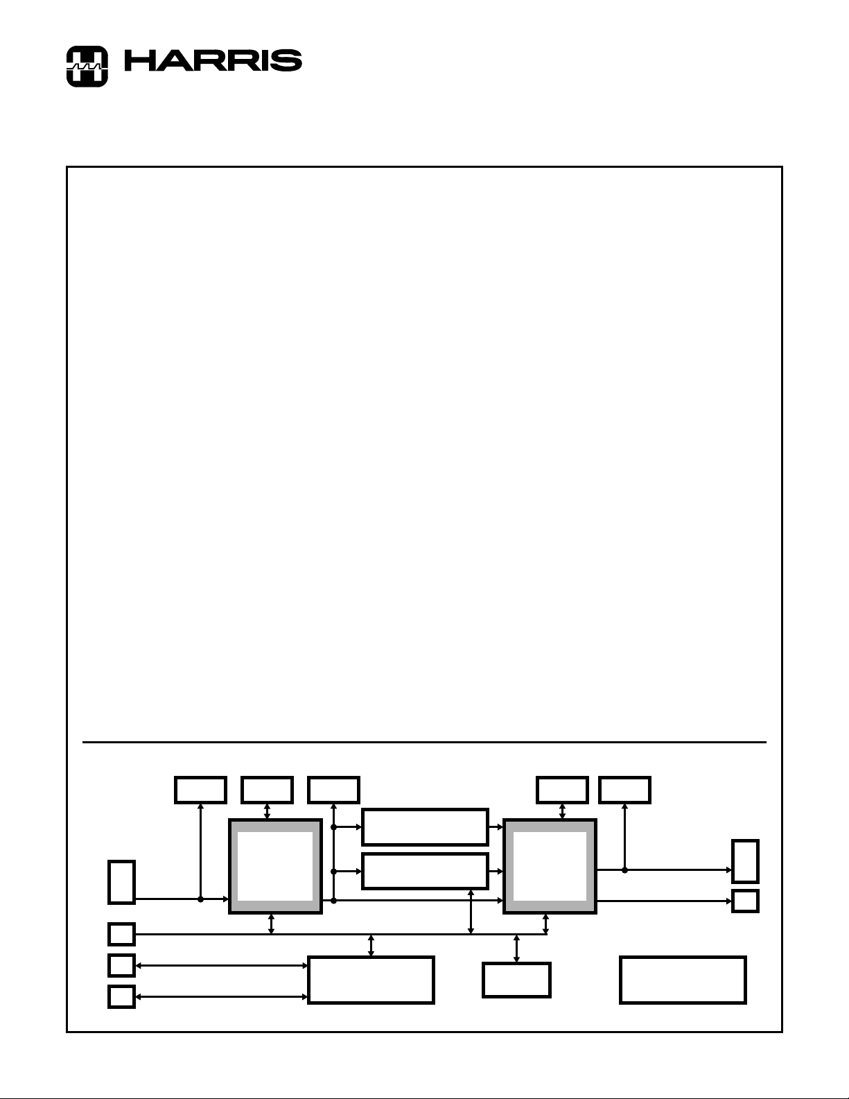
Circuit Board
Figure 1 illustrates the major functions of the evaluation circuit
board. The circuit board is a 3U x 160mm VME/Eurocard form
factor with dual 96 pin I/O connectors. The connector pinouts
conforms to the VME P2 connector pinout (i.e. power pin
positions located on the middle row and I/O pin positions
located on the outer rows). Data enters the board on the P1 96
pin plug connector and is routed through the HSP50110 Digital
Quadrature Tuner to the HSP50210 Digital Costas Loop. Data
leaves the board through the P2 plug connector. For
applications requiring custom filtering, the HSP43124 Serial I/O
FIR Filter can be inserted in the data path prior to the Digital
Costas Loop. An on-board microcontroller , a Motorola 68HC11,
provides a control and status interface to the serial port of a
Personal Computer (PC) running the Control/Status software
program. The microcontroller EPROM contains the Motorola
monitor program which provides the serial interface to the PC.
Test connectors are provided at ke y signal and control locations
in the demodulator circuit.
Functional Block Diagram
JP1 JP2 JP3
HSP43124 (U4)
96 PIN
CONNECTOR
P1
IF OR BASEBAND
SAMPLED DATA
JP9
JP7
JP6
CAUTION: These devices are sensitive to electrostatic discharge. Users should follow proper IC Handling Procedures.
© Harris Corporation 1996
Copyright
SERINADE™ is a trademark of Harris Corporation.
RS232
CONFIGURE/CONTROL
HSP50110
DIGITAL
QUADRATURE
TUNER
(U1)
MICROCONTROLLER
MICROCONTROLLER
SERIAL I/O FIR FILTER
HSP43124 (U5)
SERIAL I/O FIR FILTER
DOWNCONVERTED
SAMPLED DATA
68HC11
(U12)
FIGURE 1.
1
8K x 8 RAM
(U13)
JP4 JP5
HSP50210
DIGITAL
COSTAS
LOOP
(U7)
I AND Q BASEBAND
DATA SYMBOLS
SERIAL I DATA
CLOCK
GENERATOR/BUFFER
(U2 AND U3)
File Number 4149
P2
JP8
Page 2
HSP50110/210EVAL
Appendices A through H contain detailed information about
Circuit Board Layout, Initial Jumper Settings, Connector Pin
Assignments, Test Header Pin definitions, Detailed Schematics, Parts List, Memory Maps and a Descriptive File List.
Control/Status Software Program
The Control/Status software program, written for DOS based
PC’s, is included in the evaluation kit. This software supports
operation of the evaluation circuit board in basic PSK
demodulator and phased locked loop (PLL) configurations.
The menu driven software program allows the user to select
a variety of demodulator and data path configurations. It calculates demodulator/PLL configuration data based on the
user menu selections, downloads configuration data to the
evaluation circuit board and displays operational status. The
calculated configuration data are the register values for the
IC’s on the evaluation board. This data is downloaded to the
evaluation circuit board microcontroller using the COM1 or
COM2 serial port on the PC. Status is read from circuit
board registers using the same serial interface and displayed on the computer screen. The downloaded configuration data is available in a text file to facilitate editing, printing,
or exporting. Additionally, the software can configure the
HSP43124 FIR filter by importing .RPT files generated using
SERINADE, a Harris filter design application.
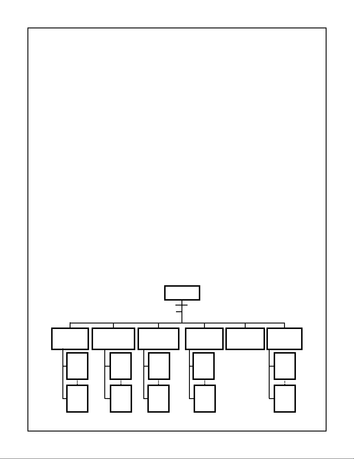
The Control/Status software MAIN MENU offers six submenus for various configuration selections and three command actions. The menu tree is illustrated in Figure 2.
The six configuration submenus are:
• Data Path/Modulation Setup Menu
• Carrier Tracking Loop Setup Menu
• Bit Synchronization Loop Setup Menu
• Acquisition/Tracking Setup Menu
• Configure Hardware Menu
• Generate Output Files
The three command actions are:
• Load Configuration File
• Save Configuration File
• Exit
A typical operational sequence is:
A. Load Configuration File.
Executing this MAIN MENU item brings up a screen with the
current file name and requests the name of the file to be
loaded. Once the new filename name is entered, this command
loads the configuration setup and returns to the MAIN MENU
screen. This command allows the user to select a previously
saved configuration file f or display, review and editing.
B. Edit Configuration File.
This is done by sequencing through each of the configura-
tion submenus and adjusting the parameters for the desired
hardware configuration.
- The DATA PATH/MODULATION SETUP MENU is used
to select clock rates, modulation type, filtering, signal
levels, SNR range and I/O formats.
- The CARRIER TRACKING LOOP SETUP MENU is
used to select loop bandwidth, loop filter order, damping
coefficient, sweep rate, and limits for both Carrier acquisition and tracking.
- The BIT SYNC LOOP SETUP MENU is used to select
loop bandwidth, loop filter order, damping coefficient,
and limits for both Bit Timing tracking and acquisition.
- The ACQUISITION AND TRACKING SETUP MENU is
used to select lock detection integration time, lock
detection thresholds and other acquisition and tracking
parameters.
C. Save Configuration File
Executing this MAIN MENU item brings up a screen with the
current file name and a request for a filename to be saved.
Once the new filename name is entered, this command
stores the configuration setup to the new file.
MAIN MENU
(6) SAVE CONFIGURATION FILE
(5) LOAD CONFIGURATION FILE
(1) (2) (3) (4) (7) (8)
DATA PATH/
MODULATION
SETUP MENU
ENTER
(1)
VALUE
MENU
ENTER
(27)
VALUE
MENU
NEW
NEW
CARRIER BIT SYNC
TRACKING LOOP
SETUP MENU
ENTER
(1) (1) (1) (1)
(15) (8) (10) (5)
NEW
VALUE
MENU
ENTER
NEW
VALUE
MENU
FIGURE 2. MENU TREE FOR THE CONTROL/STATUS SOFTWARE
LOOP
SETUP MENU
ENTER
NEW
VALUE
MENU
ENTER
NEW
VALUE
MENU
(9) EXIT
ACQUISITION
AND
TRACKING
SETUP MENU
ENTER
NEW
VALUE
MENU
ENTER
NEW
VALUE
MENU
GENERATE CONFIGURE
OUTPUT FILES
REVIEW MENU
2
HARDWARE
MENU
ENTER
NEW
VALUE
MENU
ENTER
NEW
VALUE
MENU
Page 3
HSP50110/210EVAL
D. Generate Output Files
This command will generate a number of intermediate files
which contain the register values for the IC’s on the evaluation
circuit board. Four of the files, IFIRCOEF.ARY, IFIRREG.ARY,
QFIRCOEF.ARY and QFIRREG.ARY, contain FIR specific configuration and coefficient data. One additional file has a suffix of
.ARY, and the prefix of the last saved configuration filename. It
contains the configuration data for the Digital Tuner and Digital
PLL chips.
E. Configure Hardware
This command accesses a menu called the HARDWARE
INTERFACE MENU. The menu allows selection of full initialization, loading of only the HSP50110 and HSP50210 IC’s,
loading of only the FIR filters, or changing only one specific
register. Full initialization should be selected the first time the
evaluation board is configured. Selection of items 1 - 5 will
create a number of .S files that transfer the configuration
data to the microcontroller on the evaluation circuit board
and call microcontroller subroutines that load the data into
the IC’s on the evaluation board.
D. Display Status
This command in the HARDWARE INTERFACE MENU config-
ures the PC screen to display a variety of status information.
Should further adjustment in the configuration be required, a
partial hardware download can be done using the same process and using a command item other than Full Initialization
in the Hardware Interface menu.
For a detailed listing of the every Menu screen, with selection item definitions, refer to Appendix I.
Configuration/Test Headers
Ten dual row test headers located on the evaluation circuit
board are used to monitor signals and set control pins. The
pin assignments for each of these headers are found in
Appendix D. Headers JP1, 3, and 5 contain the data path signals for monitoring the input and output busses of the
HSP50110 and HSP50210. Input pins for the HSP50110 hav e
pull down resistors. Headers JP2 and JP4 contain the I/O signals for the HSP50110/210 that are not in the data path. JP2
also selects the clock source for the board. Header JP6 contains the microcontroller control signals. A microprocessor
RESET function can be implemented by installing a “normally
open” push button switch across pins 9 and 10 of JP6. Header
JP7 contains the RS232 connection to the 68HC11 microcontroller. Header JP8 contains the HSP50210 output I data at
RS232 levels. Header JP9 allows monitoring of the microcontroller busses. JP10 contains +5VDC and ground.
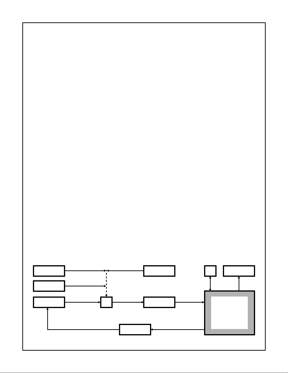
Typical Evaluation Configuration
Figure 3 identifies the equipment configuration in a typical
performance evaluation setup. A test data stream is generated in the Bit Error Rate Tester (BERT) and used by the
modulator to generate a modulated IF signal. Noise and
other signal impairments are summed with the IF signal, filtered, then digitized by an A/D converter. The digitized IF
signal is routed to the circuit board. From the evaluation
board, recovered clock and data are returned to the BERT
for calculation of BER performance. A computer is connected via RS232 for control and status of the circuit board.
A logic analyzer is shown for viewing real time display of the
I/Q constellations, filter outputs, or error detector outputs of
the HSP50210 during operation.
Getting Started
Evaluation Circuit Board Configuration and Set Up
1. ___ Connect the serial cable, provided in the e valuation kit,
to JP7 on the evaluation board.
2. ___ Connect the DB-9 end of the serial cable to the COM
port on the PC.
3. ___ Connect +5 VDC to the ev aluation board at J1, using
the cable provided in the kit. The lead with the white
stripe is the +5 VDC wire. (The board draws approximately 400mA when operated with the on board
40MHz oscillator)
4. ___ V erify that JP2 has pin 29 jumpered to pin 30, as well
as pin 31 jumpered to pin 32. Installing these jumpers
utilizes the on board 40MHz oscillator. (Set the jumpers on JP2, to connect pin 29 to 30, if the on board
oscillator is not desired. Supply an external clock
source on pins 3 and 4 of JP1.)
The circuit board is ready for use when the +5 VDC is
applied to it.
ADJ. CHANNEL
NOISE SOURCE
MODULATOR
INTERFERENCE
CONTROL/STATUS
MODULATED IF COMPOSITE IF
DATA AND CLOCK
FIGURE 3. TYPICAL DEMODULATOR PERFORMANCE EVALUTAION CONFIGURATION
Σ
BERT
IF FILTER
AND A/D
DATA AND CLOCK
DIGITIZED IF
PC
RS232
HSP50110/210EVAL
EVALUATION BOARD
3
LOGIC
ANALYZER
TEST
DAT A
Page 4

HSP50110/210EVAL
Requirements for the Control/Status Software Program
In order to properly operate the Control/Status software program included in the evaluation kit, the PC m ust meet the f ollowing requirements:
PC/XT/AT or 100% compatible with a minimum of 640K of
RAM
DOS Version 3.0 or higher
One serial port with 9 pin connector (COM1 or COM2)
Installing the Software
The instructions that follow will load both the
HSP50110/210EVAL and SERINADE software onto the “C”
drive of the computer. If you do not wish to run the software
from the “C” drive, consult your computer user’s manual for
operation from another drive. It is always smart practice to
backup original disks prior to installing the software on your
computer
1. ___ Insert the HSP50110/210EVAL disk in Drive A and
copy the contents of the distribution diskette to the
target directory on Drive C.
2. ___ Insert the SERINADE disk into Drive A and install the
software carefully following the instructions found on
page 1-1 and 1-2 of the SERINADE User’s Manual.
The software must be run from the new target directory
established on the C drive.
Running the Control/Status Software Program
1. ___ On the PC, change the directory to be the one where
the Control/Status software is installed.
2. ___ Start the program by typing: DEMODEVB <Enter>.
The program will prompt for which COM port to use.
3. ___ Select a COM port and press <Enter>. The MAIN
MENU screen will appear. It will look like Figure 4.
4. ___ Select item (5) and load B128RRC.CFG (or a configuration of your choice)
5. ___ Select MAIN MENU item (1), by typing: 1<Enter>. The
DATA PATH/MODULATION MENU will appear. It
should match the entries found in Figure 5.
6. ___ Make any adjustments to the parameters b y entering
the desired item number and editing it.
7. ___ Repeat Steps 5 and 6 for MAIN MENU items (2), (3),
and (4). These Menus should match the items found
in Figures 6, 7 and 8 respectively.
8. ___ Select MAIN MENU item (6) by typing 6<Enter>. This
will save the edited file.
9. ___ Select MAIN MENU item (7) by typing 7<Enter>. This
will calculate the configuration parameters and generate the.AR Y files.
10. ___ V erify that the hardware test configur ation is ready
and that the evaluation circuit board has power applied to it. (Note that menu items 1 through 7 can be
executed without the evaluation circuit board connected to the PC)
11. ___ Select MAIN MENU item (8) by typing 8<Enter>.
12. ___ Select HARDW ARE INTERFACE MENU item (1) by
typing 1<Enter>. The menu should match Figure 9.
Item (1) does a full initialization of the board. Items (2)
and (3) of the HARDWARE INTERFACE MENU,
download the selected configurations to the
HSP50110 and HSP50210, item (2), and the
HSP43124 FIRs, item (3). Item (1) should be selected whenever the board has been reset. After that,
item (2) can be selected for a faster update . Items (1)
or (3) should be selected whenever a ne w FIR coefficient file is chosen.
13. ___ Select HARDW ARE INTERFACE MENU item (4) by
typing 4<Enter>. This starts the polling of the circuit
board for status. Some of the status is only v alid when
the demod is tracking and thus, is not displayed during acquisition. The status display is toggled on and
off by repeatedly selecting item (4).
--------------------------------------------------------------------
HSP50110/210 EVALUATION BOARD SOFTWARE
--------------------------------------------------------------------
MAIN MENU
(1) Data Path/Modulation Setup
(2) Carrier Tracking Loop Setup
(3) Bit Sync Loop Setup
(4) Acquisition and Tracking Setup
(5) Load Configuration File
(6) Save Configuration File
(7) Generate Output Files
(8) Configure Hardware
(9) Exit
ENTER SELECTION:
(C) Harris Semiconductor 1995 Version 1.0
FIGURE 4. MAIN MENU SCREEN
4
Page 5

HSP50110/210EVAL
-------------------------------------------------------------------
HSP50110/210 EVALUATION BOARD SOFTWARE
--------------------------------------------------------------------
DATA PATH / MODULATION MENU
Current File Name.\B128RRC
(1) Master Clock Freq. . . . . . . . . . . . . . . . . . . . . . .40000000 Hz
(2) Input Sample Rate. . . . . . . . . . . . . . . . . . . . . . .40000000 Hz
(3) Input Mode. . . . . . . . . . . . . . . . . . . . . . . . . . . . . Gated
(4) DQT Input Samples. . . . . . . . . . . . . . . . . . . . . .Real
(5) DQT Input Format. . . . . . . . . . . . . . . . . . . . . . .Offset Bin
(6) L.O. Center Freq.. . . . . . . . . . . . . . . . . . . . . . . .+5000000 Hz
(7) Data Modulation . . . . . . . . . . . . . . . . . . . . . . . .BPSK
(8) Baud Rate. . . . . . . . . . . . . . . . . . . . . . . . . . . . . . 128000 Hz
(9) DQT Output Rate . . . . . . . . . . . . . . . . . . . . . . .256000 Hz
(10) I.F . NBW . . . . . . . . . . . . . . . . . . . . . . . . . . . . . 750000 Hz
(11) DQT Filter . . . . . . . . . . . . . . . . . . . . . . . . . . . .CIC w/ comp
(12) DCL RRC Filter . . . . . . . . . . . . . . . . . . . . . . .Enabled
(13) DCL I&D. . . . . . . . . . . . . . . . . . . . . . . . . . . . .Bypassed
(14) HSP43124 . . . . . . . . . . . . . . . . . . . . . . . . . . . .Bypassed
(15) Es/No (min) . . . . . . . . . . . . . . . . . . . . . . . . . . .+0 dB
(16) Es/No (max . . . . . . . . . . . . . . . . . . . . . . . . . . .+100 dB
(17) Es/No (design). . . . . . . . . . . . . . . . . . . . . . . . .+6 dB
(18) A/D backoff (min.) . . . . . . . . . . . . . . . . . . . . .12 dB
(19) A/D backoff (max.). . . . . . . . . . . . . . . . . . . . .18 dB
(20) DCL Output Vector. . . . . . . . . . . . . . . . . . . . . -6 dBFS
(21) DQT Output Level . . . . . . . . . . . . . . . . . . . . . -12 dBFS
(22) DCL Detect. Level . . . . . . . . . . . . . . . . . . . . . -12 dBFS
(23) Slicer Threshold. . . . . . . . . . . . . . . . . . . . . . . . 0.25
(24) DQT AGC Slew Rate . . . . . . . . . . . . . . . . . . . 30 dB/sec
(25) DCL AGC Slew Rate . . . . . . . . . . . . . . . . . . .10 dB/sec
(26) AGC Limits. . . . . . . . . . . . . . . . . . . . . . . . . . .FULL RANGE
(27) Output Mux Control . . . . . . . . . . . . . . . . . . . . 7
(0) MAIN MENU
ENTER SELECTION:
--------------------------------------------------------------------
HSP50110/210 EVALUATION BOARD SOFTWARE
--------------------------------------------------------------------
BIT SYNC LOOP MENU
(1) Bit Sync Loop Upper Limit . . . . . . . . . . . . . . .+500 Hz
(2) Bit Sync Loop Lower Limit . . . . . . . . . . . . . . .-500 Hz
(3) Symbol Tracking. . . . . . . . . . . . . . . . . . . . . . . .2nd order
(4) Bit Sync Fractional Loop BW (Acq) . . . . . . . . 0.01
(5) Bit Sync Fractional Loop BW (Trk . . . . . . . . . 0.003
(6) Bit Sync Loop Damping. . . . . . . . . . . . . . . . . . 1
(7) Symbol Tracking Bits . . . . . . . . . . . . . . . . . . . .32
(8) Bit Sync Serial Output @ . . . . . . . . . . . . . . . . . Fclk
(0) MAIN MENU
ENTER SELECTION:
FIGURE 7. BIT SYNC LOOP MENU
--------------------------------------------------------------------
HSP50110/210 EVALUATION BOARD SOFTWARE
--------------------------------------------------------------------
ACQUISITION / TRACKING (LOCK DETECTION) MENU
(1) Lk Det Integ. Time (A CQ) . . . . . . . . . . . . . . . .96 symbols
(2) Lk Det Integ. Time (TRK) . . . . . . . . . . . . . . . .512 symbols
(3) Lk Det Threshold (ACQ) . . . . . . . . . . . . . . . . .40 deg.
(4) Lk Det Threshold (TRK) . . . . . . . . . . . . . . . . .43 deg.
(5) Lock Verify Cycles (TRK Integ. times). . . . . . 8
(6) False Lock / Freq Error Integ . . . . . . . . . . . . . .False Lock
(7) False Lock Detector. . . . . . . . . . . . . . . . . . . . . . Disabled
(8) False Lock Threshold . . . . . . . . . . . . . . . . . . . .45
(9) False Lock Sweep Count . . . . . . . . . . . . . . . . . 8
(10) Acquisition T ype. . . . . . . . . . . . . . . . . . . . . . .Swept
(0) MAIN MENU
ENTER SELECTION:
FIGURE 5. DATA PATH/MODULATION MENU
----------------------------------------------------------------------
HSP50110/210 EVALUATION BOARD SOFTWARE
----------------------------------------------------------------------
CARRIER TRACKING LOOP MENU
(1) Carrier Tracking Loop Upper Limit. . . . . . . . +30000 Hz
(2) Carrier Tracking Loop Lower Limit. . . . . . . . -30000 Hz
(3) Carrier Tracking. . . . . . . . . . . . . . . . . . . . . . . . 2nd order
(4) Carrier Fractional Loop BW (Acq) . . . . . . . . 0.03
(5) Carrier Fractional Loop BW (Trk. . . . . . . . . . 0.01
(6) Carrier Tracking Loop Damping . . . . . . . . . . 0.707
(7) AFC.. . . . . . . . . . . . . . . . . . . . . . . . . . . . . . . . . Disabled
(8) Frequency Error Gain (Acq). . . . . . . . . . . . . . n/a Hz/Hz
(9) Frequency Error Gain (Trk) . . . . . . . . . . . . . . n/a Hz/Hz
(10) Delay in Discriminator . . . . . . . . . . . . . . . . . 0.5 baud
(11) Acquisition Sweep Rate . . . . . . . . . . . . . . . . 5 Hz/baud
(12) Carrier Tracking Bits to DQT. . . . . . . . . . . . 32
(13) Carrier Tracking . . . . . . . . . . . . . . . . . . . . . . Lead & Lag to DQT
(14) DCL Serial Output Clock (SerClk) . . . . . . . Fclk/8
(15) Carrier Serial Output @ . . . . . . . . . . . . . . . . Fclk
(0) MAIN MENU
ENTER SELECTION:
FIGURE 6. CARRIER TRACKING LOOP MENU
FIGURE 8. ACQUISITION/TRACKING (LOCK DETECTION)
--------------------------------------------------------------------
HSP50110/210 EVALUATION BOARD SOFTWARE
--------------------------------------------------------------------
HARDWARE INTERFACE MENU
(1) Full Initialization
(2) Load filename.ary Registers to Board
(3) Load filter.ary FIR coefs to Board
(4) Turn Status Display ON
(5) Change one register
(0) MAIN MENU
ENTER SELECTION:
FIGURE 9. HARDWARE INTERFACE MENU
The hardware is now configured as a 128 KBPS BPSK
demodulator with root raised cosine data filters. The Control/Status software is now configured to report status to the
screen so that you can evaluate the performance of the
demodulator configuration.
5
Page 6

HSP50110/210EVAL
Advanced Evaluation Configurations
Terminal/PC With Terminal Emulation Control of
Evaluation Board
The user has the option of communicating directly with the
evaluation board microcontroller monitor program using a
“dumb terminal” or a PC with a communications program
such as Terminal under Microsoft Windows
settings are 4800 baud, 8 bits, 1 stop bit, and no parity. The
download (.DLD) files generated by the Control/Status software contain monitor commands for loading the HSP registers. A terminal emulator program can be used to send these
files to the monitor program as a text file download. Faster
transfers result when using “Line at a Time” versus other
download options because the text transfers wait only for the
prompt string “>”.
1. On reset, the monitor program sends a greeting.
2. Press enter and the monitor will return a prompt.
3. To display a help screen, send “?”.
4. To initialize the 68HC11 to communicate with the HSP
parts enter the following commands:
MM 005A
00 88 08 03 04 01
This sets up the memory map and address decoding.
The memory map for the 68HC11 is provided in Appendix G.
A list of the file types on the distribution disk with a brief
description, is provided in Appendix H.
For further information on the MC68HC11K4 microprocessor, reference the following Motorola data books:
Motorola M68HC11 Reference Manual (M68HC11RM/AD)
Motorola MC68HC11K4 Technical Data (MC68HC11K4/D)
The source code for the monitor program (BUFK4.ASM,
.S19, and .LST) is available on the Motorola’s bulletin board
for microprocessor products. It can be accessed using either
anonymous ftp to freeware.aus.sps.mot.com or via modem
at (512) 891-3733 (8 bits, 1 stop bit, no parity).
Serial Data Output at RS232 Levels
A user can read the I symbol serial data directly from the
output bus of the HSP50210 at RS232 levels using JP8-3.
JP4 must have pin 31 jumpered to pin 32 to connect the output data to RS232 driver, U8.
Using SERINADE Designed Filters
Once SERINADE has been used to synthesize a filter, it is
possible to use this filter design in the FIR filters in the
demodulator on the evaluation board. This procedure
assumes that the SERINADE .RPT files are available for
import. Version 1.1 or higher is recommended.
™
. The COM port
Root Raised Cosine Filter
Several filter coefficient files have been included on the
HSP50110/210EVAL disk because the SERINADE program
does not compute square root of raised cosine filters. These
files are provided for import into SERINADE. Select FIR
type:
Imported
SERINADE will add the control register values for the raised
cosine filter and any half band stages that you might select.
SERINADE will generate the .RPT files as before. The root
raised cosine coefficient files have been provided for alpha =
0.2, 0.35, 0.4, and 0.5 at 2X, 4X, and 8X baud rate. The
impulse response length is 8 baud intervals for all cases.
Non Demodulator Configurations
If other configurations are needed, the software can be used
to generate computed data gain, filtering, and I/O settings.
These settings can be downloaded as a file, as before, or
modified as individual register IC parameters after an initial
download.
on the SERINADE design menu screen.
Detailed Circuit Description
The reader should reference the detailed schematics,
found in Appendix E, while reading the detailed circuit
description.
Signal Path
The signal path begins with digitized IF data samples input
to the P1 connector. These data samples form a complex
data bus, 10 bits of each I and Q samples, which is routed to
the input of the HSP50110 Digital Quadrature Tuner, U1. Pull
down resistors, RZ1-3, are provided for unused inputs. If the
input sampled IF data format is offset binary and it is a real
signal (either I or Q data only), the MSB of the unused input
bus (I or Q) should be pulled up to a logic “1” to set the bus
to midscale. Because all of the P1 signals pass through test
header JP1, it can also serve as an input connector. In
addition to the P1 signals, JP1 has two HSP50110 signals,
the input enable signal DQTENI# and the output signal
DQTHI/LO. JP1 also has the AGCLVL input signal for the
68HC11 internal A/D converter. The external access to the
DQTENI# signal provided on P1 allows the HSP50110 to be
evaluated in both the gated input and interpolated input
modes. The DQTHI/LO, when externally filtered, can be
used in designing an Automatic Gain Control (AGC) circuit
around the IF A/D converter. Both the threshold and logic
sense of the DQTHI/LO signal are programmable. The
AGCLVL signal is the return path for an external analog AGC
signal. The AGCLVL signal is digitized and read by the
processor.
Microsoft Windows™ is a trademark of Microsoft Corporation.
6
Page 7

HSP50110/210EVAL
The digital downconverted complex parallel b us output of the
HSP50110 Digital Quadrature Tuner is routed to the
HSP50210 Digital Costas Loop, U7. This parallel bus is also
routed through test header JP3. The baseband data ready
signal (BBDRDY#), HSP50210 input AGC signal
(DCLHI/LO), and the 68HC11 imbedded A/D input
(AGCLVL) are also provided on JP3. The BBDRDY# provides synchronization for the parts following the HSP50110.
The DCL HI/LO is provided to allow external filtering for use
of this signal in designing an AGC circuit around the A/D
converter when the HSP50110 is bypassed. The AGCLVL
signal is the return path for an external analog AGC signal.
The AGCLVL signal is digitized and read by the processor.
Test header JP2 contains the remaining output signals from
the HSP50110, control inputs for the HSP50110, and card
clock source/polarity jumpered selections.
The serial outputs of the Digital Quadrature Tuner, IBB0 and
QBB0, are routed to two HSP43124 Serial I/O filters, U4 and
U5, and then to the U7, Digital Costas Loop, serial input.
This filtered serial signal path is provided for those applications requiring special filtering beyond the Root Raised
Cosine (RRC) and Integrate & Dump (I&D) filters offered by
the HSP50210 Digital Costas Loop integrated circuit. An
octal register, U6, is provided to ensure that setup and hold
times are guaranteed up to the 45MHz maximum clock rate
of the FIR filters. Selection of signal routing to the FIR filters
is done in the DATA PATH/MODULATION MENU, item (14).
A set of .ARY files (two each for I and Q FIR filter) is generated by the program. Selecting the DATA PATH/MODULATION MENU item (14) and identifying a .RPT file, sets the
FIR filter response. The HARDWARE INTERFACE MENU
item (3) allows the download of only the FIR filter files and is
useful when only the FIR filters need to be changed.
The I and Q output busses from the HSP50210, and the high
speed output clock are routed through the test header JP5 to
the 96 pin connector, P2. When a jumper is placed between
JP-5 pins 29 and 31, the data rate clock (DATACLK) is provided on both JP5 and P2. The I/Q output enable and loop
freeze control inputs, along with the loop tracking outputs of
the HSP50210, are routed to header JP4. Pin assignments
for all connectors and headers are provided in Appendices C
and D.
Clocking
Microcontroller
An on-board microcontroller, a 68HC11, provides the control
and status of the evaluation board. It includes RAM, EPROM
(programmed with Motorola’s BUFFALO™ monitor program),
EEPROM, a serial port, address decoding, a synchronous
serial port, an A/D converter, and other features. U8 provides
the RS232 drive levels for the serial port, JP7. U13 is an 8K x 8
static RAM for 68HC11 program and data storage. U14 provides the address decoding for the HSP parts. U15 provides
additional address decoding that is brought to JP9. U9 and U10
are the power-on reset and optional switch controlled reset v oltage detectors. U11 is the 8MHz oscillator for the 68HC11. JP8
provides an RS232 port for the I channel received symbol data
stream when JP4 pins 31 and 32 are jumpered. JP6 provides
for jumpering the operating mode of the 68HC11, installing a
RESET switch, and applying 12.25V for the programming the
68HC11 EPROM.
The jumper options for JP6 are:
Pins 1-2 Description
No Jumper IRQB = 1 (Note 1)
Jumpered HSP50110 LKDET INT = IRQB
Pins 3-4 Pins 5-6 Description
Jumpered Jumpered Special HC11 Bootstrap Mode
No Jumper Jumpered Special HC11 Test Mode
Jumpered No Jumper Special HC11 Single Chip Mode
No Jumper No Jumper Expanded HC11 Mode (Note 1)
Pins 7-8 Description
No Jumper XIRQ = Program Voltage (pin 8) (Note 1)
Jumpered XIRQ = 0 (GND)
Pins 9-10 Description
No Jumper OPERATE (Note 1)
Jumpered Microprocessor RESET (temporary connec-
tion only, is required for RESET)
NOTE:
1. Indicates normal operational mode for the evaluation board
JP9 is provided for monitoring the microcontroller and provides access to the address bus, the data bus, the SPI port,
control signals, and general purpose I/O signals.
Jumpered Options
The clock associated with the digitized IF samples can be
input at P1 pin 20 if the card is configured for external clock
(JP2 header pins 29-30). If the card is configured for internal
40MHz reference clock (JP2 header pins 29-31 and 30-32),
then the 40MHz reference clock is output on P1 pin 20.
Three ACT86 gates (U3) isolate the on-board and off-board
clock signals, allow different polarities for the clocks, and
provide the 3.0V minimum V
Installing a jumper between J2-25 and 26 inverts clock for
the Digital Quadrature Tuner, the Digital PLL and the FIR Filters. Installing a jumper between J2-27 and 28 inverts the
high speed output clock.
BUFFALO™ is a trademark of Motorola.
required by the HSP parts.
IH
Power Supply Connections
The +5V input jack is J1. The +5V can be supplied from any
generic +5VDC/500mA AC/DC power adapter. A cable that
has the mating connector to J1 is provided with the ev aluation
kit for use with a standard laboratory power supply. A zener
diode provides some protection against overvoltage or polarity reversal. The J1 input is fused f or protection from e xcessiv e
current draw . V
the JP10 header, or at either the P1 or P2 connectors. The
supply pins on these 96 pin connectors match VME P2 pins
for +5V and ground and also are compatible with the supply
pins on other Harris evaluation boards. The evaluation board
draws approximately 400mA at 40MHz.
7
and GND connections can also be made at
CC
Page 8
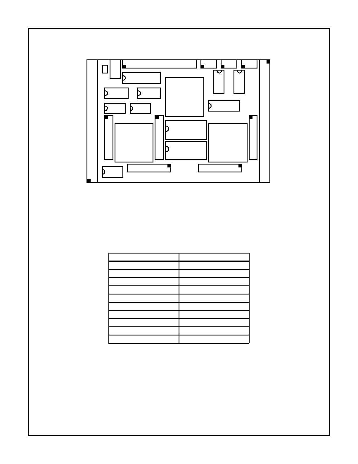
Appendix A
Circuit Board Layout
HSP50110/210EVAL
Appendix B
P1
J1
JP10
ACT04 ACT86
JP1
OSC
8Kx8 RAM
HSP50110
JP6JP7JP8JP9
OSC
ACT138ACT138
JP2
MC68HC11K4
ACT574
JP3
HSP43124
HSP50210
HSP43124
JP4
RS232
JP5
P2
Initial Jumper Settings
INITIAL JUMPER SETTINGS
FROM TO
JP2-1 JP2-2
JP2-3 JP2-4
JP2-5 JP2-6
JP2-7 JP2-8
JP2-9 JP2-10
JP2-29 JP2-30
JP4-1 JP4-2
JP4-3 JP4-4
JP4-5 JP4-6
JP4-7 JP4-8
8
Page 9
Appendix C
P1 and P2 Connector Pin Assignations
HSP50110/210EVAL
P1 CONNECTOR PIN ASSIGNMENTS
PIN SIGNAL PIN SIGNAL PIN SIGNAL
A1 N/C B1 +5V C1 GND
A2 N/C B2 GND C2 N/C
A3 N/C B3 N/C C3 N/C
A4 N/C B4 N/C C4 N/C
A5 QI0 B5 N/C C5 QI1
A6 GND B6 N/C C6 QI2
A7 QI3 B7 N/C C7 QI4
A8 QI5 B8 N/C C8 QI6
A9 QI7 B9 N/C C9 QI8
A10 QI9 B10 N/C C10 GND
A11 N/C B11 N/C C11 N/C
A12 N/C B12 GND C12 N/C
A13 N/C B13 +5V C13 N/C
A14 N/C B14 N/C C14 II0
A15 II1 B15 N/C C15 GND
A16 II2 B16 N/C C16 II3
A17 II4 B17 N/C C17 II5
A18 II6 B18 N/C C18 II7
A19 II8 B19 N/C C19 II9
A20 GND B20 N/C C20 CLKIN
A21 GND B21 N/C C21 N/C
A22 GND B22 GND C22 N/C
A23 GND B23 N/C C23 N/C
A24 GND B24 N/C C24 N/C
A25 GND B25 N/C C25 N/C
A26 N/C B26 N/C C26 N/C
A27 N/C B27 N/C C27 N/C
A28 N/C B28 N/C C28 N/C
A29 N/C B29 N/C C29 N/C
A30 N/C B30 N/C C30 GND
A31 N/C B31 GND C31 N/C
A32 N/C B32 +5V C32 N/C
P2 CONNECTOR PIN ASSIGNMENTS
PIN SIGNAL PIN SIGNAL PIN SIGNAL
A1 N/C B1 +5V C1 GND
A2 N/C B2 GND C2 N/C
A3 N/C B3 N/C C3 N/C
A4 N/C B4 N/C C4 N/C
A5 BO0 B5 N/C C5 BO1
A6 GND B6 N/C C6 BO2
A7 BO3 B7 N/C C7 BO4
A8 BO5 B8 N/C C8 BO6
A9 BO7 B9 N/C C9 BO8
A10 BO9 B10 N/C C10 GND
A11 N/C B11 N/C C11 N/C
A12 N/C B12 GND C12 N/C
A13 N/C B13 +5V C13 N/C
A14 N/C B14 N/C C14 AO0
A15 AO1 B15 N/C C15 GND
A16 AO2 B16 N/C C16 AO3
A17 AO4 B17 N/C C17 AO5
A18 AO6 B18 N/C C18 AO7
A19 AO8 B19 N/C C19 AO9
A20 GND B20 N/C C20 CLKOUT
A21 GND B21 N/C C21 GPOUT
A22 GND B22 GND C22 N/C
A23 GND B23 N/C C23 N/C
A24 GND B24 N/C C24 N/C
A25 GND B25 N/C C25 N/C
A26 N/C B26 N/C C26 N/C
A27 N/C B27 N/C C27 N/C
A28 N/C B28 N/C C28 N/C
A29 N/C B29 N/C C29 N/C
A30 N/C B30 N/C C30 GND
A31 N/C B31 GND C31 N/C
A32 N/C B32 +5V C32 N/C
9
Page 10
HSP50110/210EVAL
Appendix D
JP1 through JP10 Test Header Pin Assignments
JP1 TEST HEADER PIN ASSIGNMENTS
PIN SIGNAL DESCRIPTION PIN SIGNAL DESCRIPTION
1 DQTHI/LO DQT HI/LO Signal 2 GND Ground
3 CLKIN Input Clock to Board 4 GND Ground
5 II9 I Input Bus Bit 9 (MSB) 6 II8 I Input Bus Bit 8
7 II7 I Input Bus BIT 7 8 II6 I Input Bus Bit 6
9 II5 I Input Bus BIT 5 10 II4 I Input Bus Bit 4
11 II3 I Input Bus BIT 3 12 II2 I Input Bus Bit 2
13 II1 I Input Bus BIT 1 14 II0 I Input Bus Bit 0 (LSB)
15 GND Ground 16 GND Ground
17 QI9 Q Input Bus Bit 9 (MSB) 18 QI8 Q Input Bus Bit 8
19 QI7 Q Input Bus Bit 7 20 QI6 Q Input Bus Bit 6
21 QI5 Q Input Bus Bit 5 22 QI4 Q Input Bus Bit 4
23 QI3 Q Input Bus Bit 3 24 QI2 Q Input Bus Bit 2
25 QI1 Q Input Bus Bit 1 26 QI0 Q Input Bus Bit 0(LSB)
27 GND Ground 28 GND Ground
29 DQTENI# DQT Input Enable 30 GND Ground
31 AGCLVL A/D Input to 68HC11 32 GND Ground
JP2 TEST HEADER PIN ASSIGNMENTS
PIN SIGNAL DESCRIPTION PIN SIGNAL DESCRIPTION
1 GND Ground 2 DQTPH1 DQT Phase Shift Bit1
3 GND Ground 4 DQTPH0 DQT Phase Shift Bit 0
5 GND Ground 6 DQTCFLD DQT Center Freq Load
7 GND Ground 8 DQTOEI# DQT Output Enable I
9 GND Ground 10 DQTOEQ# DQT Output Enable Q
11 GND Ground 12 DQTLOTP DQT L.O. Test Point
13 GND Ground 14 SPH0 Bit Sync Phase Bit 0
15 GND Ground 16 SPH1 Bit Sync Phase Bit 1
17 GND Ground 18 SPH2 Bit Sync Phase Bit 2
19 GND Ground 20 SPH3 Bit Sync Phase Bit 3
21 GND Ground 22 SPH4 Bit Sync Phase Bit 4
23 GND Ground 24 SSTRB# Bit Sync Strobe
25 GND Ground 26 INVDCLK Invert Demod Clock
27 GND Ground 28 INVCKOUT Invert Output Clock
29 CLKIN Input Clock to Board 30 MSTRCLK Master Clock Node
31 DRVCLK Clock Driver 32 OSCCLK Oscillator Output
NOTE: T o input the cloc k to the board, connect pin 29 to 30; to source the clock from the on-board oscillator, connect pin 29 to 31 and pin 30 to 32.
10
Page 11

HSP50110/210EVAL
JP3 TEST HEADER PIN ASSIGNMENTS
PIN SIGNAL DESCRIPTION PIN SIGNAL DESCRIPTION
1 DCLHI/LO DCL HI/LO Signal 2 GND Ground
3 DEMODCLK Chipset Master Clock 4 GND Ground
5 IBB9 I Baseband Bit 9 (MSB) 6 IBB8 I Baseband Bit 8
7 IBB7 I Baseband Bit 7 8 IBB6 I Baseband Bit 6
9 IBB5 I Baseband Bit 5 10 IBB4 I Baseband Bit 4
11 IBB3 I Baseband Bit 3 12 IBB2 I Baseband Bit 2
13 IBB1 I Baseband Bit 1 14 IBB0 I Baseband Bit 0 (LSB)
15 GND Ground 16 GND Ground
17 QBB9 Q Baseband Bit 9 (MSB) 18 QBB8 Q Baseband Bit 8
19 QBB7 Q Baseband Bit 7 20 QBB6 Q Baseband Bit 6
21 QBB5 Q Baseband Bit 5 22 QBB4 Q Baseband Bit 4
23 QBB3 Q Baseband Bit 3 24 QBB2 Q Baseband Bit 2
25 QBB1 Q Baseband 1 26 QBB0 Q Baseband Bit 0 (LSB)
27 GND Ground 28 GND Ground
29 BBDRDY# DCL Input Enable 30 GND Ground
31 AGCLVL A/D Input to 68HC11 32 GND Ground
JP4 TEST HEADER PIN ASSIGNMENTS
PIN SIGNAL DESCRIPTION PIN SIGNAL DESCRIPTION
1 GND Ground 2 OEA# A Bus Output Enable
3 GND Ground 4 OEB# B Bus Output Enable
5 GND Ground 6 FRZBS Disable Baud Track
7 GND Ground 8 FRZCAR Disable Carrier Track
9 GND Ground 10 THRESH Level Detector Out
11 GND Ground 12 SOFSYNC Baud Offset Sync
13 GND Ground 14 SOF Baud Rate Offset
15 GND Ground 16 COFSYNC Carrier Offset Sync
17 GND Ground 18 COF Carrier Offset
19 GND Ground 20 SLOWCLK Slow Serial Clock
21 GND Ground 22 No Connect
23 GND Ground 24 No Connect
25 GND Ground 26 No Connect
27 GND Ground 28 No Connect
29 GND Ground 30 No Connect
31 RXDI RS232 Driver Input 32 AO9 I Channel MSB (AOUT9)
11
Page 12

HSP50110/210EVAL
JP5 TEST HEADER PIN ASSIGNMENTS
PIN SIGNAL DESCRIPTION PIN SIGNAL DESCRIPTION
1 No Connect 2 GND Ground
3 CLKOUT Output Clock 4 GND Ground
5 AO9 A Output Bus Bit 9 6 AO8 A Output Bus Bit 8
7 AO7 A Output Bus Bit 7 8 AO6 A Output Bus Bit 6
9 AO5 A Output Bus Bit 5 10 AO4 A Output Bus Bit 4
11 AO3 A Output Bus Bit 3 12 AO2 A Output Bus Bit 2
13 AO1 A Output Bus Bit 1 14 AO0 A Output Bus Bit 0
15 GND Ground 16 GND Ground
17 BO9 B Output Bus Bit 9 18 BO8 B Output Bus Bit 8
19 BO7 B Output Bus Bit 7 20 BO6 B Output Bus Bit 6
21 BO5 B Output Bus Bit 5 22 BO4 B Output Bus Bit 4
23 BO3 B Output Bus Bit 3 24 BO2 B Output Bus Bit 2
25 BO1 B Output Bus Bit 1 26 QI0B B Output Bus Bit 0
27 GND Ground 28 GND Ground
29 DATACLK Output Symbol Clock 30 GND Ground
31 GPOUT Jumper to Pin 29 to Connect
DATACLK to P2
32 GND Ground
JP6 TEST HEADER PIN ASSIGNMENTS
PIN SIGNAL DESCRIPTION PIN SIGNAL DESCRIPTION
1 LKDETINT Interrupt From 50210 2 IRQB 68HC11 Interrupt Input
3 GND Ground 4 MODB (Note) 68HC11 Mode Select
5 GND Ground 6 MODA (Note) 68HC11 Mode Select
7 GND Ground 8 No Connect
9 PULLDWN Pull Down Resistor 10 RSTSW Reset Switch Input
NOTE: Mode Definitions (A,B)
00--Special bootstrap mode
01--Special test mode
10--Single chip mode
11--Expanded mode (normal mode for eval board)
See the 68HC11K4 data sheet for further explanation.
JP7 RS232 HEADER PIN ASSIGNMENTS
PIN SIGNAL DESCRIPTION PIN SIGNAL DESCRIPTION
1 No Connect 2 No Connect
3 TX1 RS232 Data From HC11 4 No Connect
5 RX1 RS232 Data To HC11 6 No Connect
7 No Connect 8 No Connect
9 GND Ground 10 No Connect
12
Page 13

HSP50110/210EVAL
JP8 RS232 HEADER PIN ASSIGNMENTS
PIN SIGNAL DESCRIPTION PIN SIGNAL DESCRIPTION
1 No Connect 2 No Connect
3 TX2 HSP50210 Buffered AO9 Data 4 No Connect
5 No Connect 6 No Connect
7 No Connect 8 No Connect
9 GND Ground 10 No Connect
JP9 TEST HEADER PIN ASSIGNMENTS
PIN SIGNAL DESCRIPTION PIN SIGNAL DESCRIPTION
1 PD0 6811 Data Bit 0 2 GND Ground
3 PD1 6811 Data Bit 1 4 WRSTRB1 GP Address Decode
5 PD2 6811 Data Bit 2 6 WRSTRB2 GP Address Decode
7 PD3 6811 Data Bit 3 8 GND Ground
9 PD4 6811 Data Bit 4 10 GND Ground
11 PD5 6811 Data Bit 5 12 GND Ground
13 PD6 6811 Data Bit 6 14 GND Ground
15 PD7 6811 Data Bit 7 16 GND Ground
17 GND Ground 18 GND Ground
19 R/Wb 6811 Read/Write 20 E 6811 Bus Enable
21 GND Ground 22 CSIO HSP Chip Select
23 PA0 6811 Address Bit 0 24 PA1 6811 Address Bit 1
25 PA2 6811 Address Bit 2 26 PA3 6811 Address Bit 3
27 PA4 6811 Address Bit 4 28 PA5 6811 Address Bit 5
29 PA6 6811 Address Bit 6 30 PA7 6811 Address Bit 7
31 GND Ground 32 GND Ground
33 PA8 6811 Address Bit 8 34 PA9 6811 Address Bit 9
35 PA10 6811 Address Bit 10 36 PA11 6811 Address Bit 11
37 PA12 6811 Address Bit 12 38 PA13 6811 Address Bit 13
39 PA14 6811 Address Bit 14 40 PA15 6811 Address Bit 15
41 GND Ground 42 GND Ground
43 GP0 General Purpose I/O 44 GP1 General Purpose I/O
45 GP2 General Purpose I/O 46 GP3 General Purpose I/O
47 GP4 General Purpose I/O 48 GP5 General Purpose I/O
49 GP6 General Purpose I/O 50 GP7 General Purpose I/O
51 GP8 General Purpose I/O 52 GP9 General Purpose I/O
53 GP10 General Purpose I/O 54 GP11 General Purpose I/O
55 GND Ground 56 GND Ground
57 SCK SPI Port Clock 58 SSB SPI Port Strobe
59 MISO SPI Port I/O 60 MOSI SPI Port I/O
P10 POWER HEADER
PIN SIGNAL DESCRIPTION PIN SIGNAL DESCRIPTION
1V
CC
+5V 2 GND Ground
13
Page 14

Appendix E
Detailed Schematics
HSP50110/210EVAL
14
Page 15

HSP50110/210EVAL
15
Page 16

HSP50110/210EVAL
16
Page 17

HSP50110/210EVAL
17
Page 18

HSP50110/210EVAL
18
Page 19

HSP50110/210EVAL
19
Page 20

HSP50110/210EVAL
20
Page 21

HSP50110/210EVAL
21
Page 22

HSP50110/210EVAL
22
Page 23

HSP50110/210EVAL
23
Page 24

HSP50110/210EVAL
24
Page 25

HSP50110/210EVAL
25
Page 26

HSP50110/210EVAL
Appendix F
Parts List
EVALUATION CIRCUIT BOARD PARTS LIST
ITEM PART NUMBER TYPE DESCRIPTION MANUFACTURER .REF DES QTY
1 XC68HC711K4CFN4 IC µProc MOTOROLA U12 1
2 HSP50110JC-52 IC Digital Quad Tuner HARRIS U1 1
3 HSP50210JC-52 IC Digital Costas Loop HARRIS U7 1
4 HSP43124PC-45 IC Serial I/O Filter HARRIS U4, 5 2
5 CD74ACT574E IC Octal Register HARRIS U6 1
6 IDT7164L20TP IC 8K x 8 SRAM IDT U13 1
7 CD74ACT04E IC Hex Inverter HARRIS U16 1
8 MC34064P-5 IC Voltage Detector MOTOROLA U10 1
9 MC34164P-5 IC Voltage Detector MOTOROLA U9 1
10 CD74ACT138E IC 3:8 Decoder HARRIS U14, 15 2
11 CD74ACT86E IC Quad XOR Gate HARRIS U3 1
12 HIN232CP IC 232 Tranceiver HARRIS U8 1
13 CO6100-40.000 IC OSC, 40MHz RALTRON U2 1
14 CO6100-8.000 IC OSC, 8MHz RALTRON U11 1
15 PTC05DAAN Conn 2 x 5 Pin Header SULLINS JP6, 7, 8 3
16 PTC30DAAN Conn 2 x 30 Pin Header SULLINS JP9 1
17 PTC25DAAN Conn 2 x 25 Pin Header SULLINS JP1-5 5
18 510AG91D20ES Socket SIP Socket, 20 Pin AUGAT XU4, 5, 13 6
19 814-AG11D Socket DIP Socket, 14 Pin AUGAT XU2, 11 2
20 821573-1 Socket 84 PLCC AMP XU1, 7, 12 3
21 4610X-101-472 RPACK 4.7K RPack 10 Pin SIP BOURNS RZ10 1
22 4610X-101-223 RPACK 22K RPack 10 Pin SIP BOURNS RZ1-9 9
23 A223M15Z5UFVVWE Cap, CER 0.022µF, 50V PHILIPS C1-23 23
24 ECS-F1VE105K Cap, Tant 1.0µF, 25V PANASONIC C24-30 7
25 ECS-F1VE106K Cap, Tant 10µF, 35V PANASONIC C31 1
26 1N5908 Diode Zener 5V MOTOROLA D1 1
27 DJ005 Conn Jack LZR J1 1
28 RUE135 Fuse Reset Fuse 1.35/2.7A RAYCHEM Z1 1
29 PTC01DAAN Conn 2 Pin Power Term SULLINS JP10 1
30 C1AXG-1036M-ND Conn 10 Pin Ribbon W/ Conn DIGIKEY .1
31 CFG09G-ND Cable 9 Pin D Conn (Female) DIGIKEY 1
32 S9000-ND Jumper Shorting Jumpers DIGIKEY 25
33 650473-5 Conn 96 Pin RT Angle, Plug AMP P1, 2 2
34 HSP5011B PWB Printed Circuit Card 1
35 DC10B Cable Power Cable LZR 1
26
Page 27

Appendix G
Memory Maps
HARDWARE AND SOFTWARE
MEMORY MAP
HSP50110/210EVAL
RAM USAGE BY DEMODEVB.EXE PROGRAM
(2352/8192 BYTES USED)
FIRST
ADDR
0000 007F 68HC11 Configuration Registers
0080 02FF 68HC11 Internal RAM B
0300 037F 68HC11 Internal RAM A
0D80 0FFF 68HC11 Internal EEPROM
HARDWARE ADDRESS DECODER 1
1400 14FF IFIR (HSP43124)
1500 15FF QFIR (HSP43124)
1600 16FF DQT (HSP50110)
1700 17FF DCL (HSP50210)
HARDWARE ADDRESS DECODER 2
2000 21FF WRSTRB1 (on JP9)
2200 23FF WRSTRB2 (on JP9)
2400 27FF WRSTRB3 (Not Connected)
EXTERNAL RAM (8K BYTES)
4000 5FFF RAM
68HC11 INTERNAL EPROM
A000 CFFF Unused
D000 FFFF MOTOROLA BUFFALO
LAST
ADDR DESCRIPTION
(1400-1407 R/W)
(1500-1507 R/W)
(1600-1604 W, 1600 R)
(1700-1705 W, 1700-1704 R)
Monitor Program
(Version BUFK42)
ADDRESS DESCRIPTION
4000-41FF IFIR Coefficients
4200-4207 IFIR Registers
4208-42FF Unused (248 Bytes)
4300-44FF QFIR Coefficients
4500-4507 QFIR Registers
4508-45FF Unused (248 Bytes)
4600-467F DCL Registers 00-31d
MSB FIRST
4680-46FF Unused (128 Bytes)
4700-471F DQT Registers 00-07
MSB First
4720-47FF Unused (224 Bytes)
4800-4FFF Unused (2048 Bytes)
5000-502F DQT Write Program
5030-50FF Unused (192 Bytes)
5100-51B2 DCL Write Program
51BF-51FF Unused (64 Bytes)
5200-526 IFIR Write Program
5270-52FF Unused (144 Bytes)
5300-536F QFIR Write Program
5370-53FF Unused (144 Bytes)
5400-546F DCL Status Program
5680-569F Status Registers
56A0-5FFF Unused (2400 Bytes)
68HC11 CONFIGURATION REGISTER
PROGRAMMING
ADDR NAME DATA COMMENT
005A CSCTR 00h No CS Cycle Stretching
005B CSCTL 88h EN, Active Low, Sync to E, 4K Block GP Priority, Bit 7 GP
005C GPCS1A 08h Address Start at 4000h
005D GPCS1C 03h No CS Interaction, Active Low, Sync TO E, 8K Block
005E GPCS2A 04h Address Start at 2000h
005F GPCS2C 01h No CS Interaction, Active Low, Sync TO E, 2K Block
27
Page 28

Appendix H
Descriptive File List
HSP50110/210EVAL
PC PROGRAM
FILE DESCRIPTION
DEMODEVB.EXE Compiled Program for PC
68HC11 FILES AND PROGRAMS
FILE DESCRIPTION
INIT.S Download to Initialize the 6811 (Define Ports,
Map Memory, etc.)
DQTWRITE.S 6811 Program to Transfer Registers to the
HSP50110
DCLWRITE.S 6811 Program to Transfer Registers to the
HSP50210
DCLSTAT.S 6811 Program to Get Status From the
HSP50210
IFIRWRIT.S 6811 Program to Transfer Coefficients to the
HSP43124 (I Channel)
QFIRWRIT.S 6811 Program to Transfer Coefficients to the
HSP43124 (Q Channel)
IFIRREGS.S S-Record File, Generated by
DMDEVAL4.EXE, Containing Register Values
for the HSP43124 (I channel)
QFIRREGS.S S-Record File, Generated by
DMDEVAL4.EXE, Containing Register Values
for the HSP43124 (Q Channel)
IFIRCOEF.S
QFIRCOEF.S
S-Record File, Generated by
DMDEVAL4.EXE, Containing Coefficients for
the HSP43124 (Both Channels)
PROGRAM EXECUTION
FILE DESCRIPTION
FILENM Holds File Prefix for Last Configuration Saved.
Loaded on Start-up/modified On Save
*.CFG Holds Menu items for Setup. Loaded by
Program When a New File is Selected (and on
Start Up Using the File in FILENM)
*.DLD Holds 6811 Monitor Commands to Download
to 50110 and 50210
*.ARY Listing of Register Values for 50110 and
50210
*.RPT Output File from SERINADE Filter Design
Program. Used to Generate Coefficient
Download Files
MISCELLANEOUS
FILE DESCRIPTION
B128RRC. (Note) Example File 128k symbols/sec, BPSK,
and RRC filtering.
NOTES.TXT Notes On Using The Eval Board and
Program
HC11MMAP.TXT Memory Map of Eval Board (Including
Program RAM Usage)
NOTE: Only one of many example files. The naming convention for
these files is:
128
RRC
FILTER TYPE
DATA RATE IN KBPS
MODULATION FORMAT
B
Modulation Formats: BPSK, QPSK, 8PSK
Data Rates: 1p2 to 2500
Filter Types: RRC, I&D, FIR
28
Page 29

HSP50110/210EVAL
Appendix I
Detailed Menu Item Descriptions
Data Path/Modulation Menu
Item 1: Master Clock Frequency
(1,000Hz to 52,000,000Hz)
Enter the frequency of the external reference input clock, or
40,000,000Hz as the frequency of the on-board oscillator.
Make sure that the evaluation board is configured for external clock before the external clock is applied to the board.
Item 2: Input Sample Rate
(1,000Hz to 52,000,000Hz)
The input sample rate is the rate that the HSP50110 ENI#
pin (JP1-29) is asserted. In interpolated mode, this should
be an integer submultiple of the master clock. In gated
mode, this is the rate the carrier and bit sync NCOs in the
50110 are updated; in interpolated mode, this is the rate that
the carrier NCO is updated--the bit sync NCO is updated at
the master clock rate. The carrier NCO in the 50210 always
updates at the master clock rate.
Item 3: Input Mode
(0; 1)
Gated = 0; Interpolated = 1.
When the input mode is gated, the new data is processed
when ENI# asserted. Pipelining is done at the master clock
rate. When the input mode is interpolated, new samples are
input when ENI# is asserted, zeros are inserted between
these samples, and the processing is done at the master
clock rate.
Item 4: DQT Input Samples
(0; 1)
Complex = 0; real = 1
If a real input is used (either I or Q only), the unused input
bus should be tied to midscale external to the HSP50110.
This will be 200h if the input format is offset binary and 0 if it
is 2s complement
Item 5: DQT Input Format
(0; 1)
0 = Twos Complement
1 = Offset Binary
Item 6: Carrier Center Freq
(-52,000,000Hz to 52,000,000Hz)
The carrier L.O. center frequency is interpreted as twos
complement, so it can be a positive or negative frequency
and select either the upper or lower sideband of a real input
signal.
Item 7: Data Modulation
(0; 1; 2; 3; 4)
0 = off, 1 = BPSK, 2 = QPSK, 3 = OQPSK, 4 = 8PSK
Item 8: Baud Rate
(1 to 56,000,000 Symbols/s)
This is the output symbol rate of the HSP50210. Note that
entering a value greater than one half the clock rate induces
excessive aliasing.
Item 9: DQT Output Rate
(1 to 56,000,000 Samples/s)
This is the output sample rate of the HSP50110. It will be a
multiple of baud rate and depends on the decimation following the HSP50110. If the integrate and dump filtering in the
HSP50210 is enabled, the HSP50110 output rate will be N
times the baud rate where N is the number of samples integrated. If the integrate and dump filtering is not used (and no
external filtering is used, the input rate to the HSP50210
should be 2x the baud.
Item 10: I.F. Noise Bandwidth
(1Hz to 26,000,000Hz)
This is the noise bandwidth of the I.F. filtering preceding the
HSP50110. This is used to compute the gain needed to
compensate for the change in SNR from the A/D to the
matched filtering.
Item 11: DQT Filtering
(0; 1; 2; 3; 4; 5)
0 = Bypass, 1 = I&D, 2 = 3CIC, 3 = I&D w/ comp,
4 = 3CIC w/ comp, 5 = X/SinX
Item 12: DCL RRC Filter
(0; 1) 0 = Bypass; 1 = Enable
The root raised cosine in the HSP50210 should be enabled if
it is the matched filter for the data. It should be bypassed if
the matched filtering is done in the HSP43124 FIR filters. It
can be enabled for out-of-band signal filtering and SNR
improvement when integrate-and-dump filtering over 2 or 4
samples is used. (Some degradation will be seen with integration over 2 or 4 samples and the RRC filter enabled.)
Item 13: DCL I&D Filtering
(0; 1; 2; 3; 4; 5)
Value 0 < = N < = 5; (2
Item 14: HSP43124 Serial Filter Enable
(0; 1)
0 = HSP43124 filters bypassed
1 = HSP43124 filters enabled
(user is then prompted for a file prefix
prefix.RPT extension assumed)
Item 15: Minimum Es/No
(-100dB to 100dB)
Enter the minimum Es/No expected. This is used to set the
data path maximum gain.
Item 16: Maximum Es/No
(-100dB to 100dB)
Enter the maximum Es/No expected. This is used to set the data
path minimum gain. Enter 100 for noise free .
N
samples integrated)
29
Page 30

HSP50110/210EVAL
Item 17: Design Es/No
(-100dB to 100dB)
Enter the design Es/No. This is used to set the carrier phase
detector operational gain. Enter 100 for noise free.
Item 18: Minimum A/D backoff
(0 to 60)
This is the minimum total power backoff at the A/D. The
nominal backoff is halfway between the minimum and max
backoff.
Item 19: Maximum A/D backoff
(0 to 60)
This is the maximum total power backoff at the A/D.
Item 20: DCL Output Vector Length
(-60 to 3)
This is the nominal HSP50210 output level set by the AGC.
This is in dB relative to full scale on either axis. Typically , this
is set to -6dB for BPSK, -3dB for QPSK, and -1.8dB for
8PSK.
Item 21: DQT Output Vector Level
(-60 to 3)
The output level for the HSP50110 is set to minimize limiting
while maximizing effective bits. With noise only, this is typically
set to -12dBFS. Since the HSP50210 can only add gain and
cannot attenuate a signal, this should be set low enough that
the output level at the HSP50210 can be achieved (for example, the HSP50110 output should not be set to -6dBFS when
the desired output of the HSP50210 is -6dBFS).
Item 22: DCL Output Level Detector Threshold
(-60 to 3)
This is the threshold for the output level detector on the
HSP50210 (THRESH#). The output pin is asserted when the
signal magnitude out of the HSP50210 exceeds this programmed threshold.
Item 23: Output Slicer Threshold
(0 to 1)
The output slicer thresholds are set based on the needs of
the FEC. The programmed level is the first of the three comparator thresholds. The thresholds are relative to the full
scale magnitude on one rail. The output format set by the
program for the soft decisions is currently signed-magnitude.
The range is 0-1. The decisions thresholds are at 1x, 2x, 3x
the programmed threshold.
Item 24: DQT AGC Slew Rate
(0 to 1,000,000)
This is the slew rate for the A GC in the HSP50110. The AGC
is updated on every output sample. Since this AGC adjusts
for changes that are out of the band of interest (FDM signals
coming and going, etc.), it is typically set to slew faster than
the AGC in the HSP50210. The value entered is in dB/s
Item 25 DCL AGC Slew Rate
(0 to 1,000,000)
This is the slew rate for the AGC in the HSP50210. This
AGC adjusts for changes in signal level due to SNR changes
or signals coming and going inside the filter band of the
HSP50110. This AGC is typically set to slew slower than the
AGC in the HSP50110. The value entered is in dB/sec
Item 26: AGC Limits
(0; 1)
0 = Computed; 1 = FULL RANGE
This value is either calculated from the bandwidths and
Es/No’s, or is entered as FULL RANGE.
Item 27: Output Multiplexer Control
(0; 1; 2; 3; 4; 5; 6; 7, 8)
0 - Isoft(2:0), Qsoft(2:0), Status(6:0), AGC(7:1)
1 - Isoft2, Qsoft2, Mag(7:0), Status6, Status0, Phase(7:0)
2 - Isoft(2:0), Qsoft(2:0), Status(6:0), FreqErr(7:1)
3 - Isoft(2:0), Qsoft(2:0), Status(6:0), GainErr(7:1)
4 - Isoft(2:0), Qsoft(2:0), Status(6:0), BitPhErr(7:1)
5 - Isoft(2:0), Qsoft(2:0), Status(6:0), CarPhErr(7:1)
6 - Isoft(2:0),Qsoft(2:0), LkAcc(6:0), LkCnt(6:0)
7 - Isoft(2:0), Qsoft(2:0), Iend(7:1), Qend(7:1))
8 -Reserved(7:0), Status5, Status6, NCOS(9:0)
The output multiplexer selects the signals that are routed to
the output bus of the HSP50210. In most cases, the soft
decisions are available at the MSBs of the AOUT bus. This
allows other nodes to be monitored without disturbing the
output data. In most cases where an error detector is
brought out, it is the bottom 7 bits of the BOUT bus. Selection 7 can be used to plot the I/Q constellation using a logic
analyzer or a pair of D/A converters.
Carrier Tracking Loop Menu
Item 1: Carrier Tracking Loop Upper Limit
(-52,000,000Hz to 52,000,000Hz)
This is the upper limit for carrier loop filter lag accumulator.
This sets the upper limit on carrier acquisition and tracking.
During acquisition, the sweep direction reverses when this
limit is reached.
Item 2: Carrier Tracking Loop Lower Limit
(-52,000,000Hz to 52,000,000Hz)
This is the lower limit for carrier loop filter lag accumulator.
This sets the lower limit on carrier acquisition and tracking.
During acquisition, the sweep direction reverses when this
limit is reached.
Item 3: Carrier Tracking Loop Order
(0; 1; 2)
0 = disabled, 1 = 1st, 2 = 2nd
When carrier tracking is disabled, the feedback path from the
HSP50210 in the HSP50110 is disabled and the complex multiplier in the HSP50210 is bypassed. In first order mode, the
phase error input to the carrier lag accumulator is zeroed. In
second order mode, the loop filter is a lead/lag type. During
acquisition, the program sets the loop to first order.
30
Page 31

HSP50110/210EVAL
Item 4: Carrier Acq. Fractional Loop Bandwidth
(0.0 to 0.125)
This is the single-sided loop noise bandwidth used for acquisition. Enter the bandwidth desired at the design SNR (it will
narrow as SNR decreases). Fractional loop bandwidth is the
ratio of the loop bandwidth to the baud rate (or the rate that
the loop filter is updated). For example a loop bandwidth of
1kHz at 100kbaud would have a FLBW of 0.01.
Item 5: Carrier Tracking Fractional Loop Bandwidth
(0.0 to 0.125)
This is the single-sided loop noise bandwidth used for track-
ing. Enter the bandwidth desired at the design SNR (it will
narrow as SNR decreases). Fractional loop bandwidth is the
ratio of the loop bandwidth to the baud rate (or the rate that
the loop filter is updated). For example a loop bandwidth of
1kHz at 100kbaud would have a FLBW of 0.01. The tracking
bandwidth is used during lock verification.
Item 6: Carrier Tracking Loop Damping Factor
(0.0 to 1.5)
This damping factor is used for acquisition and tracking.
Enter the damping desired at the design SNR
Item 7: Carrier AFC Function Enabled
(0; 1)
0 = Off; 1 = On
This item enables/disables the frequency error term to the
carrier loop lag accumulator during both acquisition and
tracking. To enable only during acquisition or tracking, zero
the AFC gain for the mode not wanted.
Item 8: AFC Error Gain (acquisition)
(0 to 26,000,000)
This is the gain for the frequency error term summed into the
carrier lag accumulator. This is in Hz/Hz (i.e. if constant
offset of 100Hz is measured and the gain is set to 100Hz/Hz,
the lag accumulator will move by 10,000Hz during one
second).
Item 9: AFC Error Gain (tracking)
(0 to 26,000,000)
This is the gain for the frequency error term summed into the
carrier lag accumulator. This is in Hz/Hz (i.e. if constant
offset of 100Hz is measured and the gain is set to 100Hz/Hz,
the lag accumulator will move by 10,000Hz during one
second).
Item 10: Delay in AFC Discriminator (x half baud)
(0; 1; 2; 3; 4)
0 = 1 samples; 1 = 2 samples;
2 = 4 samples; 3 = 8 samples, and 4 = 16 samples
The frequency offset is calculated by differencing the carrier
phase error after a delay (dp/dt). The delay is in half baud
intervals (for this program). Longer delays give higher gains.
Aliasing can occur in the detector if the filtering is not tight
enough for the delay chosen. The delay can be set to 1, 2, 4,
8, or 16 samples (0.5, 1, 2, 4, or 8 baud intervals).
Item 11: Acquisition Sweep Rate
(0Hz/baud to 1,000,000Hz/baud)
This is the amount that the lag accumulator is incremented
each time the loop filter runs (during swept acquisition
mode) or each time the lock detector times out (during
stepped acquisition mode).
Item 12: Carrier Tracking Bits To DQT
(0; 1; 2; 3)
0 = 8, 1 = 16, 2 = 24, and 3 = 32 bits.
This is the number of bits of the offset frequency sent from
the HSP50210 to the HSP50110. At higher data rates, fewer
bits can be used since the ratio between the clock rate and
the loop bandwidth can be lower. This allows for faster
updates and less delay around the loop.
Item 13: Carrier Tracking Mode
(0; 1; 2)
0 = lead and lag terms to DQT
1 = lead to DCL, lag to DQT
2 = lead and lag terms to DCL
These tracking modes offer a trade-off between delay around
the loop and how well the signal is kept centered in the filtering.
Mode 0 has the longest delay around the loop; mode 1 has a
shorter delay for the lead term, so wider loop bandwidths can
be used while the signal is still centered in the filtering; mode 2
has the shortest delay and uses the HSP50110 as a fixed
tuner. Mode 2 allows the widest loop bandwidths , but the carrier
offset must be small relative to the baud rate.
Item 14: DCL Slow Serial Output Clock
(2; 4; 8; 16)
If the frequency offset serial output from the HSP50210 is
routed to a destination instead of the HSP50110 (a D/A, an
NCO), the serial data can be output at a submultiple of the
master clock. The master clock/slower clock selection is
done in menu item 15. Options are Fclk/N where N = 2, 4, 8,
or 16.
Item 15: Carrier Serial Output
(0; 1)
If the frequency offset serial output from the HSP50210 is
routed to a destination other than the HSP50110 (a D/A, an
NCO), the serial data can be output at a submultiple of the
master clock. The master clock/slower clock selection is
done here, and the speed of the slower clock slow clock is
selected in menu item 14. The options are: Fclk (the master
clock) and serial clock.
Bit Sync Loop Menu
Item 1: Bit Sync Loop Upper Tracking Limit
(-26,000,000 to 26,000,000)
This is the upper limit for bit sync loop filter lag accumulator.
This sets the upper limit on symbol acquisition and tracking.
Item 2: Bit Sync Loop Lower Tracking Limit
(-26,000,000 to 26,000,000)
This is the lower limit for bit sync loop filter lag accumulator.
This sets the lower limit on symbol acquisition and tracking.
31
Page 32

HSP50110/210EVAL
Item 3: Bit Sync Loop Order
(0; 1; 2)
0 = disabled, 1 = 1st, 2 = 2nd
When symbol tracking is disabled, the feedback path from
the HSP50210 in the HSP50110 is disabled. In first order
mode, the phase error input to the bit sync lag accumulator
in the loop filter is zeroed. In second order mode, the loop filter is a lead/lag type.
Item 4: Bit Sync Acquisition Fractional Loop Bandwidth
(0.0 to 0.125)
This is the single-sided loop noise bandwidth used for acqui-
sition. Enter the bandwidth desired at the design SNR (it will
narrow as SNR decreases. Fractional loop bandwidth is the
ratio of the loop bandwidth to the baud rate (or the rate that
the loop filter is updated). For example a loop bandwidth of
1kHz at 100kbaud would have a FLBW of 0.01.
Item 5: Bit Sync Tracking Fractional Loop Bandwidth
(0.0 to 0.125)
This is the single-sided loop noise bandwidth used for tracking.
Enter the bandwidth desired at the design SNR. Fractional loop
bandwidth is the ratio of the loop bandwidth to the baud rate (or
the rate that the loop filter is updated). For example a loop
bandwidth of 1kHz at 100kbaud would have a FLBW of 0.01.
Item 6: Bit Sync Loop Damping Factor
(0.0 to 1.5)
This damping factor is used for acquisition and tracking.
Enter the damping desired at the design SNR.
Item 7: Symbol Tracking Bits
(0; 1; 2; 3)
0 = 8, 1 = 16, 2 = 24, and 3 = 32.
This is the number of bits of the offset frequency sent from
the HSP50210 to the HSP50110. At higher data rates, fewer
bits can be used since the ratio between the clock rate and
the loop bandwidth can be lower. This allows for faster
updates and less delay around the loop.
Item 8: Bit Sync Serial Output at
(0; 1)
0 = Fclk (master clock);
1 = Serial clock (the SLOCLK output pin)
If the frequency offset serial output from the HSP50210 is
routed to a destination other than the HSP50110 (a D/A, an
NCO), the serial data can be output at a submultiple of the
master clock. The master clock/slower clock selection is
done here, and the speed of the slower clock slow clock is
selected in menu item 14 of the carrier loop menu. If the
tracking is done via the HSP50110, the master clock must
be used.
Lock Detector Menu
Item 1: Lock Detector Integration Time (Acquisition)
(1 to 1025)
This is the number of baud times that the magnitude of the
carrier phase error is integrated before making decisions
when searching for potential lock points during acquisition.
Item 2: Lock Detector Integration Time (Tracking)
(2 to 1025)
This is the number of baud times that the magnitude of the
carrier phase error is integrated to when verifying a potential
lock points and during tracking.
Item 3: Lock Detector Acquisition Threshold
(In Degrees)
(0 to 180)
This is the average magnitude of the carrier phase error over
the acquisition integration time. This is the decision threshold for potential lock points.
Item 4: Lock Detector Tracking Threshold (In Degrees)
(0 to 180)
This is the average magnitude of the carrier phase error over
the verification and tracking integration. This is the threshold
used to switch back to acquisition mode.
Item 5: Lock Verify Cycles (TRK Integration times)
(0 to 15)
This is the number of lock detector integration periods that
loop must be in lock before the state machine transitions
from the verify to the lock state.
Item 6: False Lock/Frequency Error Integ
(0; 1)
0 = freq error; 1 = false lock
This item selects whether the false lock accumulator integrates the magnitude of the frequency error or the (square
wave) f alse loc k decisions when deciding whether a potential
lock point is actually a false lock point.
Item 7: False Lock Detector
(0; 1)
0 = off; 1 = on
This item enables/disables false lock detection.
Item 8: False Lock Threshold
(0 to Discriminator Range)
This sets the false lock threshold in % of symbols that indi-
cate (square wave) false lock or Hz of freq error.
Item 9: False Lock Sweep Count
(0 to 15)
This is the number of lock detector integration times that
sweep is forced to move beyond a false lock point.
32
 Loading...