

Page 1

HSD/HSE6800+
SD/HD Serial Digital Video Distribution
Amplifiers
Installation and Operation Manual
Edition F
175-000191-00
Page 2

Page 3

Preliminary—Contents are proprietary and confidential. Do not photocopy or distribute.
HSD/HSE6800+
SD/HD Serial Digital Video Distribution
Amplifiers
Installation and Operation Manual
Edition F
January 2010
Page 4

Copyright
Information
Copyright © 2003, 2005-2006, 2010 Harris Corporation, 1025 West NASA
Boulevard, Melbourne, Florida 32919-0001 U.S.A. All rights reserved. This
publication supersedes all previous releases. Printed in Canada.
This product and related documentation are protected by copyright and are
distributed under licenses restricting their use, copying, distribution, and
decompilation. No part of this product or related documentation may be
reproduced in any form by any means without prior written authorization of Harris
Corporation and its licensors, if any.
This publication could include technical inaccuracies or typographical errors.
Changes are periodically added to the information herein; these changes will be
incorporated into new editions of the publication. Harris Corporation may make
improvements and/or changes in the product(s) and/or the program(s) described in
this publication at any time.
Warranty
Information
The limited warranty policy provides a complete description of your warranty
coverage, limitations, and exclusions, as well as procedures for obtaining warranty
service. To view the complete warranty, visit our website.
This publication is provided “as is” without warranty of any kind, either express or
implied, including, but not limited to, the implied warranties of merchantability,
fitness for a particular purpose, or non-infringement.
Page 5

Contents
Preface
Manual Information .......................................................................................... vii
Revision History ..........................................................................................vii
Writing Conventions ................................................................................. viii
Obtaining Documents ............................................................................... viii
Unpacking/Shipping Information ........................................................................ix
Safety Standards and Compliances ......................................................................x
Safety Terms and Symbols ............................................................................x
Restriction on Hazardous Substances (RoHS) Directive ..................................x
Waste from Electrical and Electronic Equipment
(WEEE) Directive ..........................................................................................xi
v
Introduction
Product Description ............................................................................................ 2
Typical Broadcast and Production Applications ............................................ 2
Main Features ............................................................................................. 2
Module Descriptions .......................................................................................... 3
Front Module .............................................................................................. 3
Back Module ............................................................................................... 5
Signal Flow ........................................................................................................ 7
Installation
Maximum 6800+ Frame Power Ratings ............................................................ 10
Unpacking the Module .................................................................................... 11
Checking the Packing List .......................................................................... 11
Setting HSD6800+ Jumpers .............................................................................. 12
Setting HSE6800+ Jumpers .............................................................................. 13
Installing 6800+ Modules ................................................................................. 14
Installing HSD/HSE6800+ Modules ............................................................. 14
Removing HSD/HSE6800+ Modules ........................................................... 14
Making Connections......................................................................................... 14
Copyright © 2003, 2005-2006, 2010, Harris Corporation
Page 6

Contents
vi
Operation
Understanding Jumper Controls ....................................................................... 16
Local Control ............................................................................................. 16
Remote Control ......................................................................................... 18
Understanding Parameter Types ....................................................................... 19
Adjustable Parameters ............................................................................... 19
Read-Only Parameters ............................................................................... 19
Operating Notes ............................................................................................... 19
Setting Locally Accessible Parameters ............................................................... 20
Setting Remotely Controlled Parameters .......................................................... 21
Changing Parameter Settings ........................................................................... 22
Recalling Default Parameter Settings ......................................................... 22
Reading Software and Hardware Versions ................................................. 22
LEDs and Alarms .............................................................................................. 23
Alarms ...................................................................................................... 23
Module Status LED .................................................................................... 23
Other LED Descriptions .............................................................................. 23
Specifications
Inputs .............................................................................................................. 26
Outputs ............................................................................................................ 26
Power Consumption ........................................................................................ 27
Propagation Delay............................................................................................. 27
Temperature .................................................................................................... 27
Start-Up Time .................................................................................................. 27
Index
Keywords ......................................................................................................... 29
Copyright © 2003, 2005-2006, 2010, Harris Corporation
Page 7
Preface
This manual details features, installation and operational procedures, and
specifications of the HSD/HSE6800+ SD/HD serial digital video distribution
amplifiers.
vii
Manual
Information
Revision History
This manual is written for engineers, technicians and operators responsible for the
installation, setup, and/or operation of the HSD/HSE6800+ SD/HD serial digital
video distribution amplifiers.
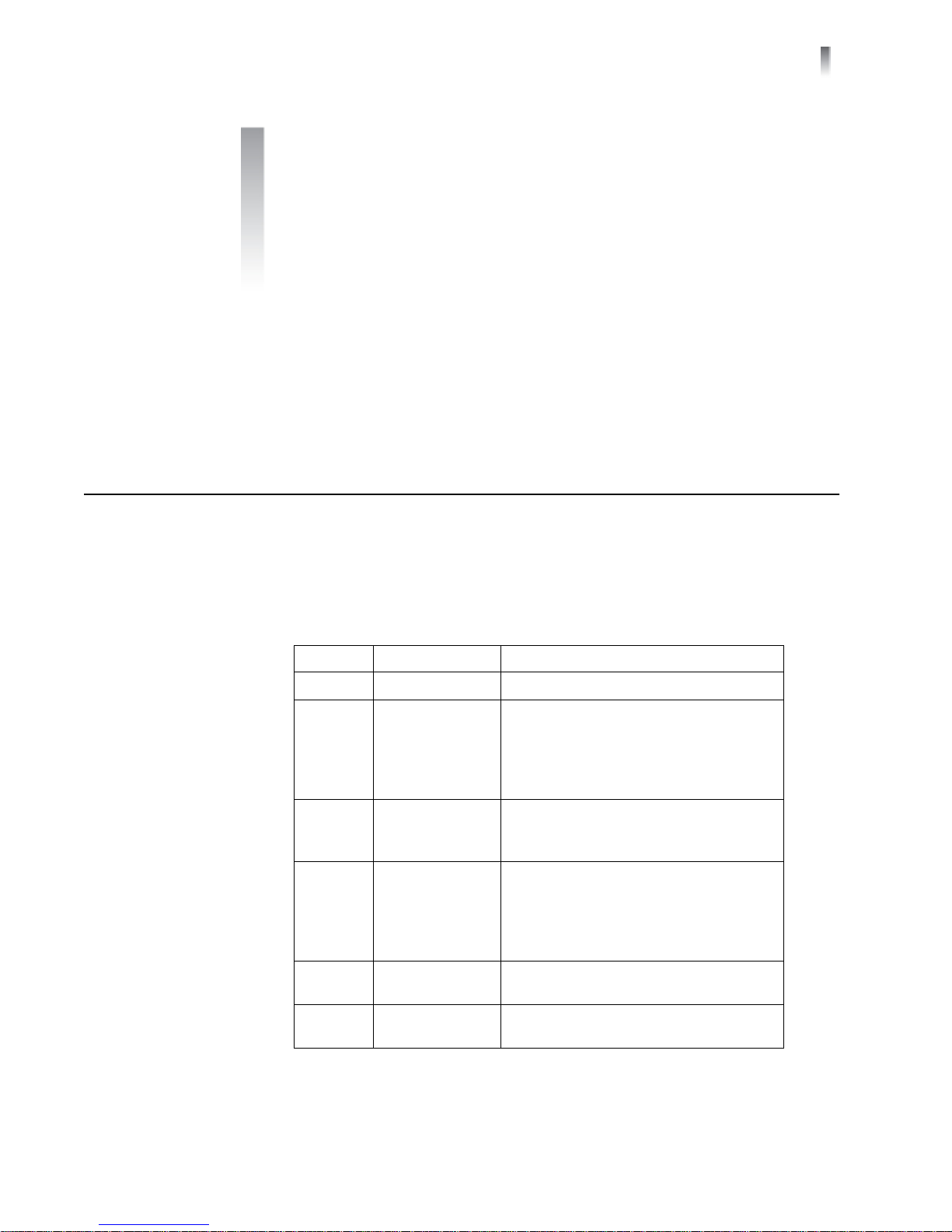
Table P-1 Manual Revision History
Edition Date Revision History
A November 2003
B December 2003
C August 2005
D January 2006
E September 2006
F January 2010
Initial release
Corrected Power specifications
Updated Remotely Controlled
Parameters table
Clarified input and output Return Loss
specifications
Added information concerning
maximum 6800+ frame power ratings
Added index
Updated FR6802+ back connector
illustrations
Moved “Troubleshooting” section to
FR6802+ Frame Installation and
Operation Manual
Updated information concerning
jumper settings
Removed reference to input
termination jumper
Copyright © 2003, 2005-2006, 2010, Harris Corporation
Page 8
viii
Preface
Writing
Conventions
To enhance your understanding, the authors of this manual have adhered to the
following text conventions:
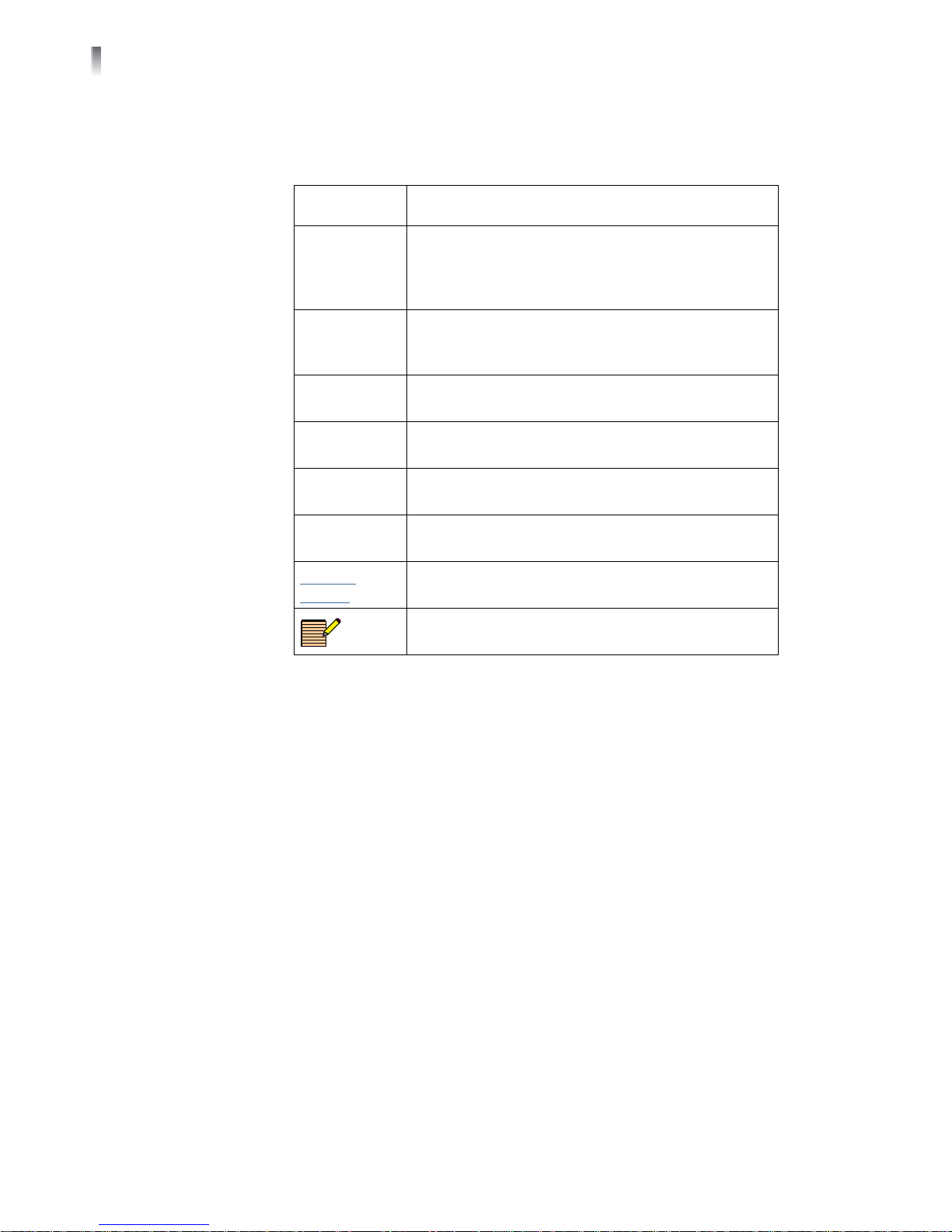
Table P-2 Manual Style and Writing Conventions
Term or
Convention
Bold Indicates dialog boxes, property sheets, fields,
Italics Indicates email addresses, the names of books or
CAPS Indicates a specific key on the keyboard, such as
Code
> Indicates the direction of navigation through a
hyperlink Indicates a jump to another location within the
Description
buttons, check boxes, list boxes, combo boxes,
menus, submenus, windows, lists, and selection
names.
publications, and the first instances of new terms and
specialized words that need emphasis.
ENTER, TAB, CTRL, ALT, or DELETE.
Indicates variables or command-line entries, such as a
DOS entry or something you type into a field.
hierarchy of menus and windows.
electronic document or elsewhere
Obtaining
Documents
Internet
address
NOTE:
Technical documents can be viewed or downloaded from our website.
Alternatively, contact your Customer Service representative to request a document.
Indicates a jump to a Web site or URL
Indicates important information that helps to avoid
and troubleshoot problems.
Copyright © 2003, 2005-2006, 2010, Harris Corporation
Page 9

HSD/HSE6800+
Installation and Operation Manual
ix
Unpacking/
Shipping
Information
This product was carefully inspected, tested, and calibrated before shipment to
ensure years of stable and trouble free service.
1 Check equipment for any visible damage that may have occurred during
transit.
2 Confirm that you have received all items listed on the packing list.
3 Contact your dealer if any item on the packing list is missing.
4 Contact the carrier if any item is damaged.
5 Remove all packaging material from the product and its associated
components before you install the unit.
Keep at least one set of original packaging, in the event that you need to return a
product for servicing. If the original packaging is not available, you can supply your
own packaging as long as it meets the following criteria:
Withstands the weight of the product
Holds the product rigid within the packaging
Leaves at least two inches of space between the product and the container
Protects the corners of the product
Ship products back to us for servicing prepaid and, if possible, in the original
packaging material. If the product is still within the warranty period, we will return
the product prepaid after servicing.
Copyright © 2003, 2005-2006, 2010, Harris Corporation
Page 10
Preface
x
Safety
Standards
and
Compliances
Safety Terms and
Symbols
See the 6800+ Safety Instructions and Standards Manual to find the safety
standards and compliances for this 6800+ series product. A safety manual is
shipped with every FR6802+ Frame Installation and Operation Manual and
can be downloaded from our website. Alternatively, contact your Customer Service
representative for a copy of this safety manual.
This product manual uses the following safety terms and symbols to identify
certain conditions or practices. See the 6800+ Safety Instructions and
Standards Manual for more information.
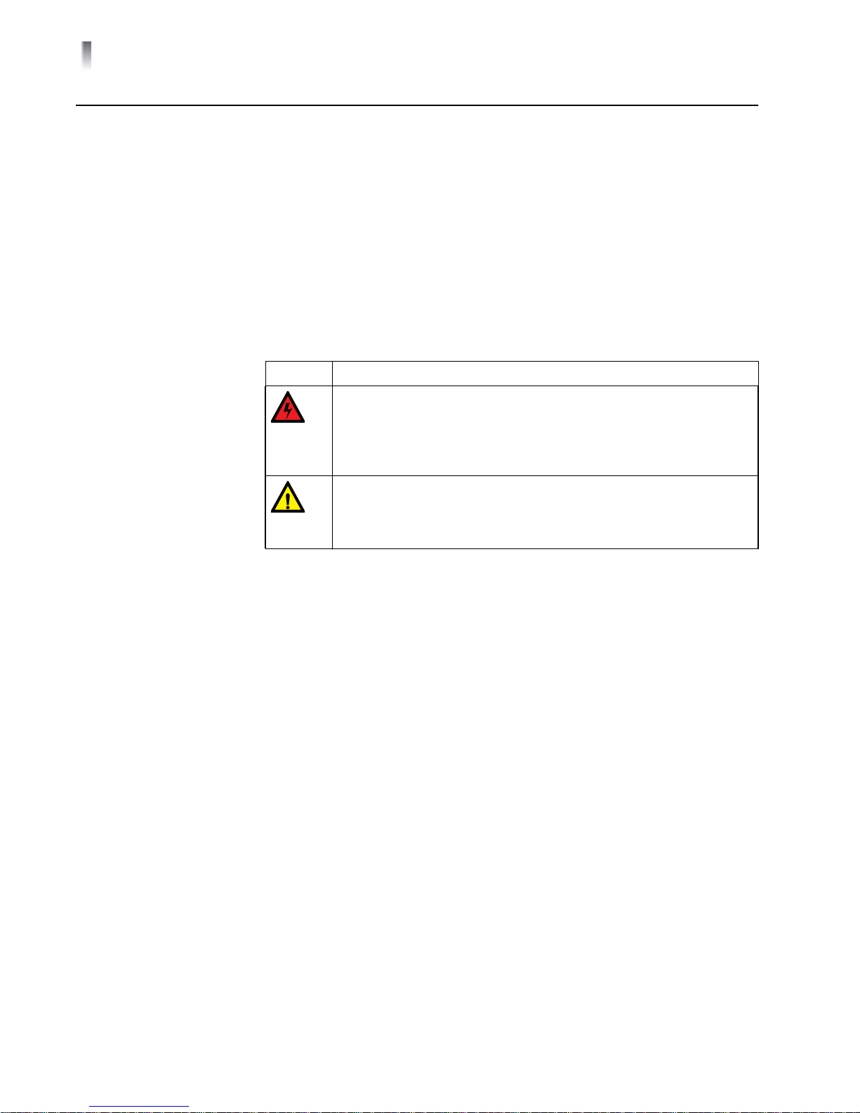
Table P-3 Safety Terms and Symbols
Symbol Description
WARNING: Identifies conditions or practices that can result in
personal injury or loss of life — high voltage is present.
Uninsulated dangerous voltage within the product’s enclosure
may be sufficient to constitute a risk of electric shock to
persons.
CAUTION: Identifies conditions or practices that can result in
damage to the equipment or other property. Important
operating and maintenance (servicing) instructions are
included in the literature accompanying the product.
Restriction on
Hazardous
Substances
(RoHS) Directive
Directive 2002 /95/EC — commonly known as the European Union (EU) Restriction
on Hazardous Substances (RoHS) — sets limits on the use of certain substances
found in electrical and electronic equipment. The intent of this legislation is to
reduce the amount of hazardous chemicals that may leach out of landfill sites or
otherwise contaminate the environment during end-of-life recycling. The Directive,
which took effect on July 1, 2006, refers to the following hazardous substances:
Lead (Pb)
Mercury (Hg)
Cadmium (Cd)
Hexavalent Chromium (Cr-V1)
Polybrominated Biphenyls (PBB)
Polybrominated Diphenyl Ethers (PBDE)
In accordance with this EU Directive, products sold in the European Union will be
fully RoHS-compliant and “lead-free.” Spare parts supplied for the repair and
upgrade of equipment sold before July 1, 2006 are exempt from the legislation.
Equipment that complies with the EU directive will be marked with a
RoHS-compliant symbol, as shown in Figure P-1.
Copyright © 2003, 2005-2006, 2010, Harris Corporation
Page 11
Figure P-1 RoHS Compliance Symbol
HSD/HSE6800+
Installation and Operation Manual
xi
Waste from
Electrical and
Electronic
Equipment
(WEEE) Directive
The European Union (EU) Directive 2002/96 /EC on Waste from Electrical and
Electronic Equipment (WEEE) deals with the collection, treatment, recovery, and
recycling of electrical and electronic waste products. The objective of the WEEE
Directive is to assign the responsibility for the disposal of associated hazardous
waste to either the producers or users of these products. As of August 13, 2005,
producers or users are required to recycle electrical and electronic equipment at
end of its useful life, and must not dispose of the equipment in landfills or by using
other unapproved methods. (Some EU member states may have different
deadlines.)
In accordance with this EU Directive, companies selling electric or electronic devices
in the EU will affix labels indicating that such products must be properly recycled.
Contact your local Sales representative for information on returning these products
for recycling. Equipment that complies with the EU directive will be marked with a
WEEE-compliant symbol, as shown in Figure P-2.
Figure P-2 WEEE Compliance Symbol
Copyright © 2003, 2005-2006, 2010, Harris Corporation
Page 12

xii
Preface
Copyright © 2003, 2005-2006, 2010, Harris Corporation
Page 13

1
1
Introduction
The HSD/HSE6800+ are SD/HD serial digital video distribution amplifiers. The
following topics are described in this chapter:
Main Features on page 2
Module Descriptions on page 3
Product Description on page 2
Signal Flow on page 7
Copyright © 2003, 2005-2006, 2010, Harris Corporation
Page 14

2
Chapter 1
Introduction
Product
Description
Typical Broadcast
and Production
Applications
Main Features
HSD6800+ and HSE6800+ are SD/HD serial digital video distribution amplifiers in
the 6800+ family:
The HSD6800+ is an SD/HD serial digital video distribution amplifier with cable
equalizing.
The HSE6800+ is an SD/HD serial digital video distribution amplifier with cable
equalizing and reclocking.
Both distribution amplifiers feature high video performance, low cost, remote
control, and diagnostic capability in our control system.
You can set up, control, and monitor the HSD/HSE6800+ either locally via a
card-edge jumper or remotely on a PC. For remote control, you can use either a
serial RS-232 or optional ICE6800+ Ethernet connection.
The HSD/HSE6800+ distribution amplifier can be used in broadcast, cable,
production, educational, and auditorium applications where a low cost method of
distributing serial digital video signals is required.
Other HSD/HSE6800+ features include the following:
One input, eight outputs for the dual slot back module; or one input, four
outputs for the single slot back module
Input signal presence detect
Automatic cable equalization
Alarm output
Automatic/manual reclock rate setting at 143 Mb/s, 177 Mb/s (manual only),
270 Mb/s SDI and ASI, 360 Mb/s, 540 Mb/s; and 1.485 Gb/s (HSE6800+ only)
Reclocking status report (HSE6800+ only)
Automatic/enforced bypass (HSE6800+ only)
Copyright © 2003, 2005-2006, 2010, Harris Corporation
Page 15

Module
Descriptions
HSD/HSE6800+
Installation and Operation Manual
3
Front Module
Figure 1-1 is a generic top-front view of a typical HSD6800+ front module. See
Figure 2-1 on page 12 for jumper locations.
Figure 1-1. Typical HSD6800+ Front Module
Figure 1-2 is a generic top-front view of a typical HSE6800+ front module. See
Figure 2-3 on page 13 for jumper locations.
Figure 1-2. Typical HSE6800+ Front Module
Copyright © 2003, 2005-2006, 2010, Harris Corporation
Page 16

4
Chapter 1
Introduction
LEDs, Switches, and Jumpers
Each 6800+ module has a number of LEDs assigned to indicated varying states/
functions. Table 1-1 briefly describes generic 6800+ LEDs, switches, and jumpers.
For HSD/HSE6800+ modules, module-specific functions are listed in Table 3-5 on
page 23. See Chapter 3, Operation for more information on specific HSD/
HSE6800+ module controls, LEDs, and jumpers.
Table 1-1 Generic 6800+ Module Features
Feature Description
Module status
LEDs
Various color and lighting combinations of these LEDs indicate
the module state. See Table 3-4 on page 23 for more
information.
Control LEDs Various lighting combinations of these control LEDs
(sometimes referred to as “Bank Select LEDs”) indicate the
currently selected bank. (This item not available on the HSD/
HSE6800+)
Monitoring
LEDs
Local/remote
control jumper
Each 6800+ module has a number of LEDs assigned to
indicate varying states/functions.
Local: Locks out external control panels and allows
card-edge control only; limits the functionality of remote
software applications to monitoring
Remote: Allows remote or local (card-edge) configuration,
operation, and monitoring of the HSD/HSE6800+
Copyright © 2003, 2005-2006, 2010, Harris Corporation
Page 17

HSD/HSE6800+
Installation and Operation Manual
5
Back Module
FR6802+ Frame Back Module
NOTE: The HSD/HSE6800+ cannot be installed in a 6800/7000 series
frame.
Figure 1-3 shows the single-width back connector and Figure 1-4 shows the
double-slot back connector used by the HSD/HSE6800+ when installed in an
FR6802+ frame.
Figure 1-3 Single-Width Back Connectors for FR6802+ Frame
Figure 1-4 Double-Width Back Connectors for FR6802+ Frame
Copyright © 2003, 2005-2006, 2010, Harris Corporation
Page 18

6
Chapter 1
Introduction
Signal Input/Output Connections for FR6802+DM Frames
Figure 1-5 shows the signal input/output connections used by the HSD/HSE6800+
when installed in an FR6802+DM frame.
Figure 1-5 Double-Slot Back Module for FR6802+DM Frames
Copyright © 2003, 2005-2006, 2010, Harris Corporation
Page 19

Signal Flow
Figure 1-6. HSD/HSE6800+ Signal Flow Diagram
HSD/HSE6800+
Installation and Operation Manual
7
Copyright © 2003, 2005-2006, 2010, Harris Corporation
Page 20

8
Chapter 1
Introduction
Copyright © 2003, 2005-2006, 2010, Harris Corporation
Page 21

2
9
Installation
CAUTION: Before installing this product, read the 6800+ Series
Safety Instructions and Standards manual shipped with every frame
installation and operation manual, or downloadable from our
website. This safety manual contains important information about
the safe installation and operation of 6800+ series products.
This chapter describes the HSD/HSE6800+ installation process, including the
following topics:
Installing HSD/HSE6800+ Modules on page 14
Making Connections on page 14
Maximum 6800+ Frame Power Ratings on page 10
Removing HSD/HSE6800+ Modules on page 14
The HSD/HSE6800+ modules have double-width back connectors that
can be installed in an FR6802+X(F) series frame. See the FR6802+ Frame
Installation and Operation Manual for details on installing back
connectors in an FR6802+ frame. on page 14
Setting HSD6800+ Jumpers on page 12
Unpacking the Module on page 11
See the FR6802+ Frame Installation and Operation Manual for information
about installing and operating an FR6802+ frame and its components.
The HSD/HSE6800+ cannot be installed in a 6800/7000 series frame.
Copyright © 2003, 2005-2006, 2010, Harris Corporation
Page 22

10
Chapter 2
Installation
Maximum
6800+ Frame
Power
Ratings
Power consumption information is listed in Chapter 4, Specifications on
page 27.
Table 2-1 describes the maximum allowable power ratings for 6800+ frames.
Note the given maximums before installing any 6800+ modules in your frame.
HSD/HSE6800+ modules can be installed in FR6802+ frames. They cannot be
installed in 6800/7000 series frames.
Table 2-1 Maximum Power Ratings for 6800+ Frames
6800+ Frame Type
FR6802+XF
(frame with AC
power supply)
FR6802+X48
(frame with DC
power supply)
Max. Frame
Power
Dissipation
120 W 20 6 W
50 W 20 2.5 W
Number of
Usable Slots
Max. Power
Dissipation Per
Slot
Copyright © 2003, 2005-2006, 2010, Harris Corporation
Page 23

HSD/HSE6800+
Installation and Operation Manual
11
Unpacking
the Module
Checking the
Packing List
Before you install the HSD/HSE6800+, perform the following:
Check the equipment for any visible damage that may have occurred during
transit.
Confirm receipt of all items on the packing list. See Checking the Packing List
for more information.
Remove the anti-static shipping pouch, if present, and all other packaging
material.
Retain the original packaging materials for possible re-use.
NOTE: Contact your Customer Service representative if parts are missing or
damaged.
See Unpacking/Shipping Information on page ix for information about
returning a product for servicing.
Table 2-2 HSD/HSE6800+ Packing List
Ordered Product Content Description
HSD/HSE6800+
One HSD/HSE6800+ front module
One HSD/HSE6800+ Installation and Operation
Manual
HSD/HSE6800+S
One HSD/HSE6800+ front module
One standard single-slot back connector
One HSD/HSE6800+ Installation and Operation
Manual
HSD/HSE6800+D
One HSD/HSE6800+ front module
One standard double-slot back connector
One HSD/HSE6800+ Installation and Operation
Manual
HSD/HSE6800+SR
HSD/HSE6800+DR
One standard single-slot back connector
One standard double-slot back connector
Copyright © 2003, 2005-2006, 2010, Harris Corporation
Page 24

12
Chapter 2
Installation
Setting
HSD6800+
Jumpers
The HSD6800+ module has one standard jumper, J3, which determines the slew
rate control. Follow this procedure to set the jumper.
1 Locate jumper set on the module. Figure 2-1 shows the standard location of
the jumper set. Pin 1 is identified by a small white triangle printed on the
module.
Figure 2-1 Location of the HSD6800+ Jumper Set
NOTE: If both HD and SD signals are to be passed through the distribution
amplifier module, choose the jumper setting for the HD slew rate (pins 2
and 3).
2 Place a jumper on the pins that correspond to the slew rate that you want. See
Figure 2-2.
Figure 2-2 HSD6800+ Jumper Set Settings
For SD slew rates, set the jumper to pins 1 and 2.
For HD slew rates, set the jumper to pins 2 and 3.
Copyright © 2003, 2005-2006, 2010, Harris Corporation
Page 25

HSD/HSE6800+
Installation and Operation Manual
13
Setting
HSE6800+
Jumpers
The HSE6800+ module has one standard jumper, which determines reclocking
mode. Follow this procedure to set the jumper.
1 Locate jumper set on the module Figure 2-3 shows the standard location of
the jumper set.
Figure 2-3 Location of the HSE6800+ Jumper Set and LEDs
2 Place a jumper on the pin that corresponds to the reclocking mode that you
want. See Figure 2-4.
Figure 2-4 HSE6800+ Jumper Set Settings
Copyright © 2003, 2005-2006, 2010, Harris Corporation
Page 26

14
Chapter 2
Installation
Installing
6800+
Modules
Installing HSD/
HSE6800+
Modules
Removing HSD/
HSE6800+
Modules
Making
Connections
The HSD/HSE6800+ modules have double-width back connectors that can be
installed in an FR6802+X(F) series frame. See the FR6802+ Frame Installation
and Operation Manual for details on installing back connectors in an FR6802+
frame.
These modules require no specialized installation procedures. See the FR6802+
Frame Installation and Operation Manual for information about installing and
operating an FR6802+ frame and its components.
These modules require no specialized removal procedures. See the FR6802+
Frame Installation and Operation Manual for information about removing
components in an FR6802+ frame.
Once you have installed the HSD/HSE6800+ module, you can connect it to the
appropriate input and outputs.
Copyright © 2003, 2005-2006, 2010, Harris Corporation
Page 27

3
15
Operation
This chapter describes how to operate the HSD/HSE6800+ using local controls
only. See the following documents for information on how to operate this product
remotely:
+Pilot Lite™ User Manual for serial control interface
CCS™ Navigator™, Pilot™, CoPilot™, or RCP-CCS-1U Remote Control Panel
Installation and Operation Manual for Ethernet control interface
The following topics are discussed in this chapter:
Changing Parameter Settings on page 22
LEDs and Alarms on page 23
Operating Notes on page 19
Setting Locally Accessible Parameters on page 20
Setting Remotely Controlled Parameters on page 21
Understanding Jumper Controls on page 16‘
Understanding Parameter Types on page 19
Copyright © 2003, 2005-2006, 2010, Harris Corporation
Page 28

16
Chapter 3
Operation
Understand-
ing Jumper
Controls
NOTE: We recommend that you use the available 6800+ software control
options (serial/local or Ethernet/remote) to aid in viewing, setting, and
confirming parameter values.
You can use the jumper on the front edge of the HSE6800+ to select either local
control or remote control reclock setting operation mode. Figure 2-3 on page 13
illustrates the location of this jumper. Figure 3-1 shows the jumper set settings for
the HSE6800+ modules.
Figure 3-1 HSE6800+ Jumper Set Settings
Local Control
NOTE: In the local control reclock setting operation mode, all of the
settings’ data status information appears on the +Pilot Lite control screen;
however, you cannot change any setting in this mode via +Pilot Lite. To
control the reclocking setting mode via +Pilot Lite, set the jumper to the
remote control reclock setting operation mode.
The local control is used to select one of three reclocking setting modes by a
jumper at the board edge: automatic, manual, and bypass.
The automatic reclocking setting mode automatically reclocks the input signal.
The RCLK LED is green and the corresponding rate indicator LED (yellow) is on
when this reclock is successful. If this reclocking attempt fails, the RCLK LED
will be red and the signal bypass the reclocker and is present at outputs.
The manual reclocking setting mode allows you to select which rate to reclock.
(See Table 3-1 for instructions on setting up the operation for reclocking each
rate.)
The bypass mode allows you to force the input data to take the bypass path,
whether it is lockable or not.
Copyright © 2003, 2005-2006, 2010, Harris Corporation
Page 29

Table 3-1 Reclocking Mode Setting
Input Signal Operation Setup
HSD/HSE6800+
Installation and Operation Manual
17
143 Mb/s
(see Figure 3-1 on page 16 for a picture of the jumper
set settings)
177 Mb/s
(see Figure 3-1 on page 16 for a picture of the jumper
set settings)
270 Mb/s
(see Figure 3-1 on page 16 for a picture of the jumper
set settings)
Set the jumper on the pin that allows the reclocker to
handle 143 Mb/s data only
If the reclocking is successful, the RCLK LED will be
green and the 143 Mb/s LED will be yellow
If the reclocking is not successful, the RCLK LED will
be red, the 143 Mb/s LED will be off, and
un-reclocked data will be present at output
Set the jumper on the pin that allows the reclocker to
handle 177 Mb/s data only
If the reclocking is successful, the RCLK LED will be
green and the 177 Mb/s LED will be yellow
If the reclocking is not successful, the RCLK LED will
be red, the 177 Mb/s LED will be off, and
un-reclocked data will be present at output
Set the jumper on the pin that allows the reclocker to
handle 270 Mb/s data only
If the reclocking is successful, the RCLK LED will be
green and the 270 Mb/s LED will be yellow
If the reclocking is not successful, the RCLK LED will
be red, the 270 Mb/s LED will be off, and
un-reclocked data will be present at output
360 Mb/s
(see Figure 3-1 on page 16 for a picture of the jumper
set settings)
540 Mb/s
(see Figure 3-1 on page 16 for a picture of the jumper
set settings)
HD
(see Figure 3-1 on page 16 for a picture of the jumper
set settings)
Set the jumper on the pin that allows the reclocker to
handle 360 Mb/s data only
If the reclocking is successful, the RCLK LED will be
green and the 360 Mb/s LED will be yellow
If the reclocking is not successful, the RCLK LED will
be red, the 360 Mb/s LED will be off, and
un-reclocked data will be present at output
Set the jumper on the pin that allows the reclocker to
handle 540 Mb/s data only
If the reclocking is successful, the RCLK LED will be
green and the 540 Mb/s LED will be yellow
If the reclocking is not successful, the RCLK LED will
be red, the 540 Mb/s LED will be off, and
un-reclocked data will be present at output
Set the jumper on the pin that allows the reclocker to
handle HD (1.485 Gb/s) data only
If the reclocking is successful, the RCLK LED will be
green and the HD LED will be yellow
If the reclocking is not successful, the RCLK LED will
be red, the HD LED will be off, and un-reclocked
data will be present at output
Copyright © 2003, 2005-2006, 2010, Harris Corporation
Page 30

Chapter 3
18
Operation
Table 3-1 Reclocking Mode Setting (Continued)
Input Signal Operation Setup
ASI
(see Figure 3-1 on page 16 for a picture of the jumper
set settings)
Remote Control
When the jumper is set to the “remote” position, the reclocker setting is handled
by +Pilot Lite only. You may select the three setting modes (automatic, manual,
and bypass) remotely via +Pilot Lite.
Set the jumper on the pin that allows the reclocker to
handle ASI data only
If the reclocking is successful, the RCLK LED will be
green and the 270 Mb/s LED will be yellow
If the reclocking is not successful, the RCLK LED will
be red, the 270 Mb/s LED will be off, and
un-reclocked data will be present at output
Copyright © 2003, 2005-2006, 2010, Harris Corporation
Page 31

HSD/HSE6800+
Installation and Operation Manual
19
Understand-
ing Parame-
ter Types
Adjustable
Parameters
Read-Only
Parameters
Most HSD/HSE6800+ parameters are adjustable, and can be set using either
card-edge controls (see Understanding Jumper Controls on page 16) or a
software application. However, there are some parameters that are considered
“read-only” and cannot be changed. Indicated by the abbreviation “[RO],” these
parameters provide status and feedback information only.
Two types of adjustable parameters can be changed using the card-edge controls:
Numerical parameters—which require you to select a value within a numerical
range
Selectable parameters—which require you to select a specific option
Both numerical and selectable parameter changes are immediate.
Use the available 6800+ software controls (serial/local or Ethernet/remote
network) to view and monitor parameter selections.
Many of the read-only parameters are also represented by LEDs on the front of the
module’s card edge. See Figure 1-1 on page 3 and Figure 1-2 on page 3 for the
location of these LEDs.
Operating
Notes
When setting the control parameters on the HSD/HSE6800+, observe the
following:
When you change a parameter, the effect is immediate. However, the module
requires up to 20 seconds to save the latest change. After 20 seconds, the new
settings are saved and will be restored if the module loses power and must be
restarted.
Copyright © 2003, 2005-2006, 2010, Harris Corporation
Page 32

20
Chapter 3
Operation
Setting
Locally Acces-
sible Parame-
ters
Table 3-2 describes HSD/HSE6800+ parameters that are accessible locally via an
on-board jumper. See Understanding Jumper Controls on page 16 for more
information about setting these parameters via jumper.
Table 3-2 Locally Accessible Parameters
Parameter Name Range Description
Module status
Signal presence
(HSD6800+ only)
Re-clockable
(HSE6800+ only)
Reclocking Mode
setting
(HSE6800+ only)
Red
Green
Red
Green
Red
Green
Auto
Manual
143
177
270
360
540
ASI
HD
Bypass
Remote
Alarm condition exists
Operating properly
Signal absent
Signal present
Not reclockable
Reclockable
Automatically select reclock mode
Manually select reclocking mode
Only 143 Mb/s can be locked
Only 177 Mb/s can be locked
Only 270 Mb/s can be locked
Only 360 Mb/s can be locked
Only 540 Mb/s can be locked
Only ASI can be locked
Only 1.485 Gb/s can be locked
Allow data to bypass reclocker
Let CCS select the control mode
Copyright © 2003, 2005-2006, 2010, Harris Corporation
Page 33

HSD/HSE6800+
Installation and Operation Manual
21
Setting
Remotely
Controlled
Parameters
NOTE: To use remotely controlled parameters, make sure that the jumper
setting is set to REMOTE. (see Figure 3-1 on page 16 for a picture of the
jumper set settings).
Table 3-3 describes HSE6800+ parameters that are accessible remotely. See your
CCS control software application manual or online help for more information on
setting and monitoring the following parameters remotely.
Table 3-3 Remotely Controlled Parameters
Parameter Name Range Description
Locked Data Rate
[RO]
Signal Present
[RO]
Reclocking Mode
None
143 Mb/s
177 Mb/s
270 Mb/s
360 Mb/s
540 Mb/s
HD
No
Yes
Auto
143 Mb/s
177 Mb/s
270 Mb/s
360 Mb/s
540 Mb/s
Bypass
HD
ASI
Returns the locking
status of the reclocker
Returns the presence of
the input signal
Sets the module working
mode
Copyright © 2003, 2005-2006, 2010, Harris Corporation
Page 34

22
Chapter 3
Operation
Changing
Parameter
Settings
Recalling Default
Parameter
Settings
Reading
Software and
Hardware
Versions
You can change HSD/HSE6800+ parameter settings locally with the card-edge
jumper or remotely by selecting the Reclocking Mode parameter setting.
You can change module parameter settings remotely via CCS software. See your
CCS control software application installation and operation manual for instructions
on how to change parameter settings.
You cannot recall default parameter settings for these modules.
The current software version of these modules can only be viewed using a
CCS-enabled control panel or a CCS software application. See the appropriate
control panel installation and operation manual, CCS software application user
manual, or CCS software application online help for information on viewing
software and hardware version numbers.
Copyright © 2003, 2005-2006, 2010, Harris Corporation
Page 35

HSD/HSE6800+
Installation and Operation Manual
23
LEDs and
Alarms
Alarms
Module Status LED
HSD/HSE6800+ modules have alarm and other information-type LEDs that report
alarm conditions or regular working status for the module. Alarm and other
information-type LEDs are available locally (via card edge). Remote alarm and
working status reporting is done via software.
Alarms are usually logged and monitored within the available 6800+ software
control applications (for example, +Pilot Lite or Pilot). See the appropriate software
control user manual or online help for more information.
Each HSD/HSE6800+ module has a module status LED that reports the state of the
module. See Figure 1-1 on page 3 for the location of this LED on the HSD6800+;
see Figure 1-2 on page 3 for the location of this LED on the HSE6800+. See
Table 3-4 for a definition of the LED colors.
Table 3-4 Status LED Descriptions
LED Color Sequence Meaning
Off There is no power to the module; the
module is not operational
Green There is power to the module; the module is
operating properly
Red There is an alarm condition
Other LED
Descriptions
Amber The module is undergoing configuration
Locally Accessible (via Card Edge)
Each 6800+ module has a number of LEDs assigned to indicated varying states/
functions. For the HSD/HSE6800+ modules, these functions are listed in Table 3-5.
Table 3-5 HSD/HSE6800+ Module-Specific Status LEDs
Name Color Function
Signal Red Input signal absent
Green Input signal present
*
RCLK
143
177
270
360
540
*
HD
*
*
*
*
*
Red Input signal cannot be reclocked
Green Input signal is reclocked
Amber Input signal is reclocked at 143 Mb/s
Amber Input signal is reclocked at 177 Mb/s
Amber Input signal is reclocked at 270 Mb/s
Amber Input signal is reclocked at 360 Mb/s
Amber Input signal is reclocked at 540 Mb/s
Amber Input signal is reclocked at 1.485 Gb/s
*
HSE6800+ modules only; not available on HSD6800+ modules
Copyright © 2003, 2005-2006, 2010, Harris Corporation
Page 36

24
Chapter 3
Operation
Remotely Accessible (via Software)
Working status information is usually monitored within the available 6800+
software control applications (for example, +Pilot Lite or Pilot); alarms are usually
logged and monitored. See the appropriate software control user manual or online
help for more information.
Copyright © 2003, 2005-2006, 2010, Harris Corporation
Page 37

4
25
Specifications
The following specification tables appear in this chapter:
Inputs on page 26
Outputs on page 26
Power Consumption on page 27
Propagation Delay on page 27
Start-Up Time on page 27
Temperature on page 27
Specifications and designs are subject to change without notice.
Copyright © 2003, 2005-2006, 2010, Harris Corporation
Page 38

26
Chapter 4
Specifications
Inputs
Outputs
Table 4-1 HSD/HSE6800+ Input Specifications
Item Specification
Signal type HD, SD, ASI
Connector BNC (IEC169-8)
Impedance 75
Return loss Better than 18 dB 5 MHz to 1.5 GHz
Maximum signal 0.88 V
Cable equalization
SD/270 Mb/s
HD
Table 4-2 HSD/HSE6800+ Output Specifications
Item Specification
Number of outputs 4 or 8
Signal type HD, SD, ASI
0 – 300 m Belden 1694A or equivalent
0 – 100 m Belden 1694A or equivalent
Connector BNC (IEC169-8)
Impedance 75
Return loss Better than 18 dB 5 MHz to 1.485 GHz typical
Better than 15 dB 5 MHz to 1.485 GHz worst
case
Signal amplitude 800 mV ± 10%
DC offset 0.0 V ± 0.5 V
Rise and fall time
SD/ASI
HD
Overshoot <10%
Jitter < 0.2 UI
400 to 700 pS
< 270 pS
Copyright © 2003, 2005-2006, 2010, Harris Corporation
Page 39

HSD/HSE6800+
Installation and Operation Manual
27
Power
Consumption
Propagation
Delay
Temperature
Table 4-3 Power Consumption Specifications
Item Specification
HSD6800+ 2.5 W
HSE6800+ 3.5 W
Table 4-4 Propagation Delay Specifications
Item Specification
HSD6800+
HSE6800+
Table 4-5 Temperature Specifications
Item Specification
1.0 ns typical
3.0 ns typical
Start-Up Time
Operating 41°F to 113°F (5°C to 45°C)
Performance 32°F to 122°F (0°C to 50°C)
Start-up time for HSD/HSE6800+ modules is approximately 10 seconds.
Copyright © 2003, 2005-2006, 2010, Harris Corporation
Page 40

28
Chapter 4
Specifications
Copyright © 2003, 2005-2006, 2010, Harris Corporation
Page 41

Keywords
Index
A
Adjustable parameters 19
Alarms 23
Applications 2
B
Back modules 5–6
C
Controls, understanding jumper 16
29
I
Input specifications 26
Installation
jumpers 12–13
modules 14
power ratings 10
unpacking modules 11
Introduction
applications 2
main features 2
module descriptions 3–6
product description 2
signal flow diagram 7
D-E
Descriptions
LEDs 23–24
modules
back modules 5–6
front modules 3
product description 2
Directives x–xi
F-G
Features 2
Front modules 3
jumpers 4
LEDs 4
switches 4
H
Hardware versions, reading 22
J-K
Jumpers
local control 16
remote control 18
setting 12–13
understanding jumper controls 16
L
LEDs
descriptions 23–24
module specific status 23
module status 23
Local control jumpers 16
M-N
Manual information vii
Modules
back modules 5–6
descriptions 3–6
front modules 3
Copyright © 2003, 2005-2006, 2010, Harris Corporation
Page 42

30
Index
jumpers 4
LEDs 4
switches 4
installing modules 14
LEDs 23–24
removing modules 14
unpacking modules ix
O
Operating temperature 27
Operation
alarms 23
changing parameter settings 22
LEDs 23–24
module status LEDs 23
local jumper controls 16
operating notes 19
parameter types 19
reading
hardware versions 22
software versions 22
recalling parameter settings 22
reclocking mode setting 17–18
remote jumper controls 18
setting parameters
locally accessible 20
remotely controlled 21
understanding jumper controls 16
Output specifications 26
P-Q
Parameters
adjustable 19
changing settings 22
parameter types 19
read-only 19
recalling settings 22
setting parameters
locally accessible 20
remotely controlled 21
Performance temperature 27
Power consumption specifications 27
Power ratings 10
Power up time 27
Product description 2
Propagation delay 27
R
Read-only parameters 19
Reclocking mode setting 17–18
Reclocking mode settings 13
Remote control jumpers 18
Remote status LEDs 23
Removing modules 14
Restriction on Hazardous Substances
(RoHS) directive x
S
Safety
compliances x
RoHS directive x
standards x
symbols x
terms x
WEEE directive xi
Setting jumpers 12–13
Shipping information ix
Signal flow diagram 7
Slew rate settings 12
Software versions, reading 22
Specifications
input 26
output 26
power consumption 27
propagation delay 27
start-up time 27
temperature 27
Start-up time 27
T
Temperature specifications 27
U-V
Unpacking modules ix, 11
Versions, reading hardware and software 22
W-Z
Waste from Electrical and Electronic
Equipment (WEEE) directive xi
Copyright © 2003, 2005-2006, 2010, Harris Corporation
 Loading...