

Page 1

HMX6801+B2/C2 and HMX6801+B4/C4
HD/SD Two- and Four-Channel
AES Multiplexers
Installation and Operation Manual
Edition C
175-000264-00
Page 2

Page 3

HMX6801+B2/C2
HMX6801+B4/C4
HD and SD Two-Channel and
Four-Channel AES Multiplexers
Installation and Operation Manual
Edition C
January 2007
Page 4

Copyright Information
Copyright 2007 Harris Corporation, 1025 West NASA Boulevard,
Melbourne, Florida 32919-0001 U.S.A.
All rights reserved. This product and related documentation are
protected by copyright and are distributed under licenses restricting
their use, copying, distribution, and decompilation. No part of this
product or related documentation may be reproduced in any form by
any means without prior written authorization of Harris Corporation
and its licensors, if any.
This publication could include technical inaccuracies or typographical
errors. Changes are periodically added to the information herein; these
changes will be incorporated into new editions of the publication.
Harris Corporation may make improvements and/or changes in the
product(s) and/or the program(s) described in this publication at any
time.
All trademarks are property of their respective owners.
Warranty Information
The Limited Warranty Policy provides a complete description of your
warranty coverage, limitations, and exclusions, as well as procedures
for obtaining warranty service. To view the complete warranty, visit
www .broadcast.harris.com/leitch
This publication is provided “as is” without warranty of any kind, either
express or implied, including, but not limited to, the implied warranties
of merchantability , fitness for a particular purpose, or non-infringement.
.
ii HMX6801+B2/C2 and HMX6801+B4/C4 Installation and Operation Manual
Page 5

Contents
Preface
Manual Information .............................................................................. vii
Purpose ...........................................................................................vii
Audience ........................................................................................ vii
Revision History ............................................................................vii
Writing Conventions .....................................................................viii
Obtaining Documents ...................................................................viii
Unpacking/Shipping Information ..........................................................ix
Unpacking a Product ....................................................................... ix
Product Servicing ............................................................................ ix
Returning a Product ........................................................................ ix
Restriction on Hazardous Substances (RoHS) Compliance ....................x
Waste from Electrical and Electronic Equipment (WEEE)
Compliance ............................................................................................ xi
Safety ....................................................................................................xii
Safety Terms and Symbols in this Manual ........... .........................xii
Chapter 1: Introduction
Overview ..................................................................................................1
Product Description ..................................................................................2
General Description ..........................................................................2
Main Features ............................................... ....................................3
Module Descriptions ................................................................................4
Front Module ....................................................................................4
Back Connectors ...............................................................................6
Signal Flow .....................................................................................10
HMX6801+B2/C2 and HMX6801+B4/C4 Installation and Operation Manual iii
Page 6

Contents
Chapter 2: Installation
Overview ............................................................................................... 11
Maximum 6800+ Frame Power Ratings ...............................................12
Unpacking the Module .......................................................................... 13
Preparing the Product for Installation ............................................13
Checking the Packing List .............................................................13
Setting Jumpers .....................................................................................14
Installing and Removing HMX6801+ Modules ................................... 15
Upgrading HMX6801+ Firmware ........................................................16
Correcting a Failed Upgrade Procedure ......................................... 20
Chapter 3: Operation
Overview ............................................................................................... 21
Operating Notes ............................................................................. 22
Audio Processing Information ..............................................................23
Audio Embedding Modes ..............................................................23
Audio Embedding Errors ............................................................... 28
Audio Output Channel Status (OutxxStat) ..................................... 28
Input Channel V-Bit Feedback (InxxVbitFb) ................................ 29
Audio Embedding Channel Source Selection ................................29
Input Audio Rate ............................................................................30
Channel Summing (PCM Processing only) ............................. ... ... 30
Non-PCM Processing ............................................................................32
Cross-Functional Parameter Changes ............................................33
Parameter Availability based on Operating Mode ................................ 35
ADS Clean Parameter ........................................................................... 36
Channel Dithering ..........................................................................36
Channel Word Length ....................................................................37
Channel Fade Rate .........................................................................37
Changing Parameter Settings .................. .............................................. 38
Recalling Default Parameter Settings ............................................39
Reading Software and Hardware Versions .................................... 39
Setting HMX6801+B2/C2 and HMX6801+B4/C4 Control Parameters 40
LEDs and Alarms ..................................................................................61
Monitoring LEDs ....... ....................................................................61
Module Status LEDs ......................................................................63
Alarms ............................................................................................ 64
iv HMX6801+B2/C2 and HMX6801+B4/C4 Installation and Operation Manual
Page 7

Chapter 4: Specifications
Overview ................................................................................................65
Inputs ......................................................................................................66
SDI Video Input ..............................................................................66
AES Balanced Input (HMX6801+B2/B4 Only) ............................67
AES Unbalanced Input (HMX6801+C2/C4 Only) ........................67
DARS Input (HMX6801+B2/C2 Only) ...................................... ...68
Outputs ...................................................................................................69
SDI Video Output ...........................................................................69
AES Balanced Output (HMX6801+B2 Only) ................................70
AES Unbalanced Output (HMX6801+C2 Only) ...........................70
Propagation Delay ..................................................................................71
Power Consumption ...............................................................................71
Operating Temperature ..........................................................................71
Appendix A: Audio Bit Manipulation
Overview ................................................................................................73
Manipulating Channel Status Bits (C-Bit) .............................................74
Manipulating Validity and User Bits (V-Bit and U-Bit) ........................77
Identifying Audio Characteristics (Audio Sampling Frequency and Word
Length) ...................................................................................................78
Contents
Appendix B: Troubleshooting Tips
Overview ................................................................................................79
General Troubleshooting Steps ..............................................................80
Common Problems and Suspected Failures ...........................................81
+ Pilot Lite Fails to Communicate with Installed Modules ............81
+ Pilot Lite Does Not Find All Modules in Frame ........................81
+ Pilot Lite or CCS Software Application Not Responding ..........81
+ Pilot Lite Cannot Control a Module Showing
in the Control Window ...................................................................82
+ Pilot Lite Status Bar Reports “Not Ready” .................................82
CCS Software Application or Remote Control Panel Does Not
Communicate with Module ................................................... .........82
Alarm Query Fails When a Device Reboots ...................................82
Frames Fail to Communicate with the PC after a Power Failure ...83
Module Does Not Seem to Work ....................................................83
Contacting Customer Service .................................................................83
HMX6801+B2/C2 and HMX6801+B4/C4 Installation and Operation Manual v
Page 8

Contents
Index
Keywords .............................................................................................. 85
vi HMX6801+B2/C2 and HMX6801+B4/C4 Installation and Operation Manual
Page 9

Manual Information
Purpose
This manual details the features, installation procedures, operational
procedures, and specifications of the HMX6801+B2/C2 and
HMX6801+B4/C4 HD and SD Two-Channel and Four-Channel
AES Multiplexers.
Preface
Audience
This manual is written for engineers, technicians, and operators
responsible for the installation, setup, and/or operation of
HMX6801+B2/C2 and HMX6801+B4/C4 HD and SD Two-Channel
and Four-Channel AES Multiplexers.
Revision History
Table P-1. Document Revision History
Edition Date Revision History
A October 2005 Initial release
B April 2006 Addition of support for SMPTE
296M, firmware upgrade tool and
index
C January 2007 Re-branding
HMX6801+B2/C2 and HMX6801+B4/C4 Installation and Operation Manual vii
Page 10

Preface
Note
Writing Conventions
To enhance your understanding, the authors of this manual have
adhered to the following text conventions.
Table P-2. Writing Conventions
Term or
Convention
Bold Indicates dialog boxes, property sheets, fields, buttons,
Italics Indicates email addresses, the names of books or
CAPS Indicates a specific key on the keyboard, such as ENTER,
Code
> Indicates the direction of navigation through a hierarchy
hyperlink Indicates a jump to another location within the electronic
Internet address
Description
check boxes, list boxes, combo boxes, menus, submenus,
windows, lists, and selection names.
publications, and the first instances of new terms and
specialized words that need emphasis.
TAB, CTRL, ALT, or DELETE.
Indicates variables or command-line entries, such as a
DOS entry or something you type into a field.
of menus and windows.
document or elsewhere
Indicates a jump to a Web site or URL
Indicates important information that helps to avoid and
troubleshoot problems.
Obtaining Documents
Product support documents can be viewed or downloaded from our
Web site. Alternatively, contact your Customer Service representative
to request a document.
viii HMX6801+B2/C2 and HMX6801+B4/C4 Installation and Operation Manual
Page 11

Unpacking/Shipping Information
Unpacking a Product
This product was carefully inspected, tested, and calibrated before
shipment to ensure years of stable and trouble-free service.
1. Check equipment for any visible damage that may have occurred
during transit.
2. Confirm that you have received all items listed on the packing list.
3. Contact your dealer if any item on the packing list is missing.
4. Contact the carrier if any item is damaged.
5. Remove all packaging material from the product and its associated
components before you install the unit.
Keep at least one set of original packaging, in the event that you need to
return a product for servicing.
Product Servicing
Preface
Except for firmware upgrades, HMX6801+B2/C2 and
HMX6801+B4/C4 modules are not designed for field servicing. All
hardware upgrades, modifications, or repairs require you to return the
modules to the Customer Service center.
Returning a Product
In the unlikely event that your product fails to operate properly, please
contact Customer Service to obtain a Return Authorization (RA)
number, then send the unit back for servicing.
Keep at least one set of original packaging in the event that a product
needs to be returned for service. If the original package is not available,
you can supply your own packaging as long as it meets the following
criteria:
• The packaging must be able to withstand the product’s weight.
• The product must be held rigid within the packaging.
• There must be at least 2 in. (5 cm) of space between the product and
• The corners of the product must be protected.
the container.
HMX6801+B2/C2 and HMX6801+B4/C4 Installation and Operation Manual ix
Page 12

Preface
Ship products back to us for servicing prepaid and, if possible, in the
original packaging material. If the product is still within the warranty
period, we will return the product prepaid after servicing.
Restriction on Hazardous Substances (RoHS) Compliance
Directive 2002/95/EC—commonly known as the European Union (EU)
Restriction on Hazardous Substances (RoHS)—sets limits on the use of
certain substances found in electrical and electronic equipment. The
intent of this legislation is to reduce the amount of hazardous chemicals
that may leach out of landfill sites or otherwise contaminate the
environment during end-of-life recycling. The Directive, which took
effect on July 1, 2006, refers to the following hazardous substances:
• Lead (Pb)
• Mercury (Hg)
• Cadmium (Cd)
• Hexavalent Chromium (Cr-V1)
• Polybrominated Biphenyls (PBB)
• Polybrominated Diphenyl Ethers (PBDE)
According to this EU Directive, all products sold in the European Union
will be fully RoHS-compliant and “lead-free.” (See our Web site,
www .broadcast.harris.com/leitch
deadlines for compliance.) Spare parts supplied for the repair and
upgrade of equipment sold before July 1, 2006 are exempt from the
legislation. Equipment that complies with the EU directive will be
marked with a RoHS-compliant emblem, as shown in Figure P-1.
Figure P-1. RoHS Compliance Emblem
x HMX6801+B2/C2 and HMX6801+B4/C4 Installation and Operation Manual
, for more information on dates and
Page 13

Waste from Electrical and Electronic Equipment (WEEE) Compliance
The European Union (EU) Directive 2002/96/EC on Waste from
Electrical and Electronic Equipment (WEEE) deals with the collection,
treatment, recovery, and recycling of electrical and electronic waste
products. The objective of the WEEE Directive is to assign the
responsibility for the disposal of associated hazardous waste to either
the producers or users of these products. As of August 13, 2005,
producers or users will be required to recycle electrical and electronic
equipment at end of its useful life, and may not dispose of the
equipment in landfills or by using other unapproved methods. (Some
EU member states may have different deadlines.)
In accordance with this EU Directive, companies selling electric or
electronic devices in the EU will affix labels indicating that such
products must be properly recycled. (See our Web site,
www .broadcast.harris.com/leitch
deadlines for compliance.) Contact your local sales representative for
information on returning these products for recycling. Equipment that
complies with the EU directive will be marked with a WEEE-compliant
emblem, as shown in Figure P-2.
, for more information on dates and
Preface
Figure P-2. WEEE Compliance Emblem
HMX6801+B2/C2 and HMX6801+B4/C4 Installation and Operation Manual xi
Page 14

Preface
Safety
Carefully review all safety precautions to avoid injury and prevent
damage to this product or any products connected to it. If this product is
rack-mountable, it should be mounted in an appropriate rack using the
rack-mounting positions and rear support guides provided. It is
recommended that each frame be connected to a separate electrical
circuit for protection against circuit overloading. If this product relies
on forced air cooling, it is recommended that all obstructions to the air
flow be removed prior to mounting the frame in the rack.
If this product has a provision for external earth grounding, it is
recommended that the frame be grounded to earth via the protective
earth ground on the rear panel.
IMPORTANT! Only qualified personnel should perform service
procedures.
Safety Terms and Symbols in this Manual
WARNING
Statements identifying conditions or
practices that may result in personal injury
or loss of life. High voltage is present.
CAUTION
Statements identifying conditions or
practices that can result in damage to the
equipment or other property.
xii HMX6801+B2/C2 and HMX6 801+B4/C4 Installation and Operation Manual
Page 15

Overview
Chapter 1
Introduction
The HMX6801+B2/C2 and HMX6801+B4/C4 are two-channel and
four-channel HD or SD audio multiplexers, respectively. The
HMX6801+B2 and HMX6801+C2 modules can embed two AES audio
signals into two groups within the SDI output signal, while the
HMX6801+B4 and HMX6801+C4 can embed four AES audio signals
into two groups. “B2/B4” versions of the modules embed balanced
signals, while “C2/C4” versions embed unbalanced signals.
The following topics are described in this chapter:
• “Product Description” on page 2
• “Module Descriptions” on page 4
• “Signal Flow” on page 10
HMX6801+B2/C2 and HMX6801+B4/C4 Installation and Operation Manual 1
Page 16

Chapter 1: Introduction
Note
Product Description
General Description
The HMX6801+B2/C2 two-channel and HMX6801+B4/C4
four-channel AES Multiplexers can (respectively) embed two and four
AES audio signals into a single 1.5 Gb/s HD or 270 Mb/s SD video
signal in both balanced and unbalanced formats.
Following SMPTE 299M and SMPTE 272M specifications, these
multiplexers are able to embed up to four AES audio signals into two
groups in the ancillary region of the SDI output signal. The sample rate
conversion on these modules can be disabled for Dolby E
audio compliancy.
These modules can be controlled and monitored in the following ways:
• Locally, via card edge
• Remotely, with CCS software applications such as + Pilot Lite
CCS Pilot
panels and other products such as NUCLEUS
Panel.
™
/compressed
™
, and CCS Navigator™, or with CCS-compliant control
™
Network Control
™
,
Four module types are available:
• HMX6801+B2 has one balanced DARS input, one unba lanced
All product versions provide
one SDI video input and a
minimum of two SDI video
outputs.
DARS input, two balanced AES input channels, and two balanced
AES output channels
• HMX6801+B4 has four balanced AES input channels and a third
SDI video output
• HMX6801+C2 has one unbalanced DARS input, two unbalanced
AES input channels, and two unbalanced AES output channels
• HMX6801+C4 has four unbalanced AES input channels and a third
SDI video output
The back connectors for both module types require two frame slots
within an FR6802+QXF or FR6802+XF frame (there is no
backward-compatibility provided for use with 6800/7000 series
frames).
2 HMX6801+B2/C2 and HMX6801+B4/C4 Installation and Operation Manual
Page 17

Main Features
Chapter 1: Introduction
HMX6801
following
• Inputs:
•Outputs:
• Automatic detection of all SMPTE 292M HD-SDI or SMPTE 259
• Audio processing amplification with controls for delay , gain, invert,
• 16-bit, 20-bit, or 24-bit audio processing (selectable word length in
• Audio test tone generation
• Individual audio gr oup assignment for each group
• Phase relationship maintena nce between groups for Dolby 5.1
• Sample rate conversion disabling on AES inputs for
+B2/C2 and HMX6801+B4/C4
:
• One SMPTE 292M HD-SDI or 259M SD-SDI input (all
HMX6801+ versions)
• One balanced DARS reference input (HMX6801+B2 only)
• One unbalanced DARS reference inpu t (HMX6801+B2/C2
only)
• Two/four balanced AES digital audio inputs
(HMX6801+B2/B4 only)
• Two/four unbalanced AES digital audio inputs
(HMX6801+C2/C4 only)
• Three (HMX6801+C4/B4) or two(HMX6801+C2/B2) SMPTE
292M HD-SDI or SMPTE 259M SD-SDI video outputs
• Two balanced AES digital audio outputs with user-selectable
source (HMX6801+B2 only)
• Two unbalanced AES digital audi o outputs with user-selectable
source (HMX6801+C2 only)
SD-SDI video standards
channel multiplexing, and averaging
channel pairs)
audio applications (Group Lock mode)
Dolby/compressed audio embedding
features include the
HMX6801+B2/C2 and HMX6801+B4/C4 Installation and Operation Manual 3
Page 18
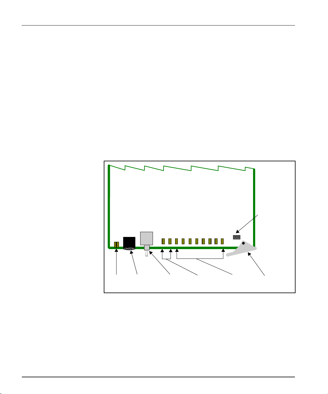
Chapter 1: Introduction
Module
status
LEDs
Mode select
rotary
switch
Navigation
toggle
switch
Monitoring
LEDs
Remote/local
control
jumper
Extractor
handle
Control
LEDs
• Programmable audio delays (up to 1.3 sec)
• Optional ancillary data space cleaning before embedding
• Card-edge LEDs to indicate audio and video signal presence and
module failure
• Serial and Ethernet remote control and monitoring
• Support for SMPTE 296M (50, 59.94, and 60 Hz rates) HD-SDI
Module Descriptions
Front Module
Figure 1-1 is a generic top-front view of a typical 6800+ module and
shows the general location of standard LEDs, controls, and jumpers.
Figure 1-1. Typical 6800+ Module
Table 1-1 on page 5 briefly describes generic 6800+ LEDs, switches,
and jumpers. See “Chapter 2: Installation” for more information on
specific HMX6801+B2/C2 and HMX6801+B4/C4 module controls,
LEDs, and jumpers.
4 HMX6801+B2/C2 and HMX6801+B4/C4 Installation and Operation Manual
Page 19

Table 1-1. Generic 6800+ Module Features
Feature Description
Chapter 1: Introduction
Module status
LEDs
Mode select
rotary switch
Navigation
toggle switch
Control LEDs Various lighting combinations of these Control LEDs
Monitoring
LEDs
Local/remote
control jumper
Various color and lighting combinations of these LEDs
indicate the module state. See “Monitoring LEDs” on
page 61 for more information.
This switch selects between various control and
feedback parameters.
This switch navigates up and down through the available
control parameters:
• Down: Moves down through the parameters
• Up: Moves up through the parameters
(sometimes referred to as “Bank Select LEDs”) indicate
the currently selected bank. See Table 3-8 "Selected
Bank as Indicated by Control LEDs"for more
information.
Each 6800+ module has a number of LEDs assigned to
indicate varying states/functions. See “Monitoring
LEDs” on page 61 for a description of these LEDs.
• Local: Locks out external control panels and allows
card-edge control only; limits the functionality of
remote software applications to monitoring
• Remote: Allows remote or local (card-edge)
configuration, operation, and monitoring of the
HMX6801+B2/C2 and HMX6801+B4/C4
HMX6801+B2/C2 and HMX6801+B4/C4 Installation and Operation Manual 5
Page 20
Chapter 1: Introduction
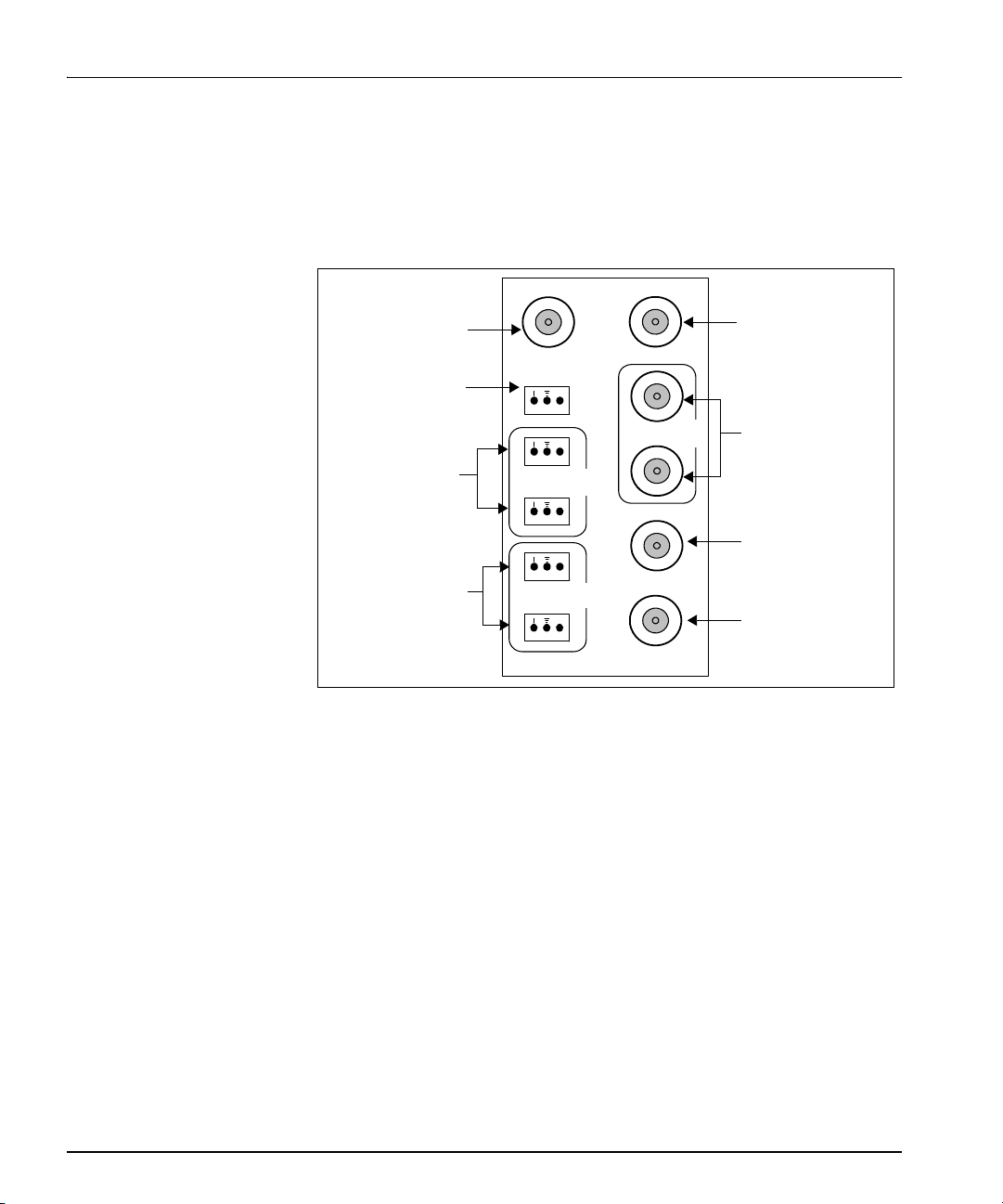
SDI IN
DATA I/O
1
2
SDI
OUT
AUX IN
DARS
IN BAL
DARS IN
1
2
AES
OUT
1
2
AES
IN
+
+
+
+
+
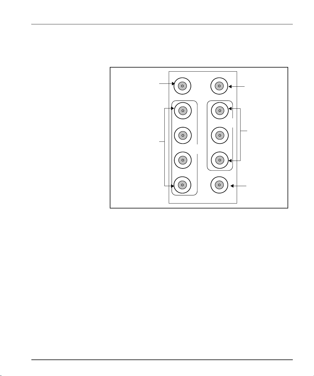
Reserved for
future use
Balanced AES
input channels
Balanced AES
output channels
SDI video outputs
SDI video input
Balanced
DARS input
Unbalanced
DARS input
Reserved for
future use
Back Connectors
HMX6801+B2
Figure 1-2 shows the double-slot back connector used by the
HMX6801+B2 module when installed in an FR6802+XF frame.
Figure 1-2. HMX6801+B2 Back Connector
6 HMX6801+B2/C2 and HMX6801+B4/C4 Installation and Operation Manual
Page 21
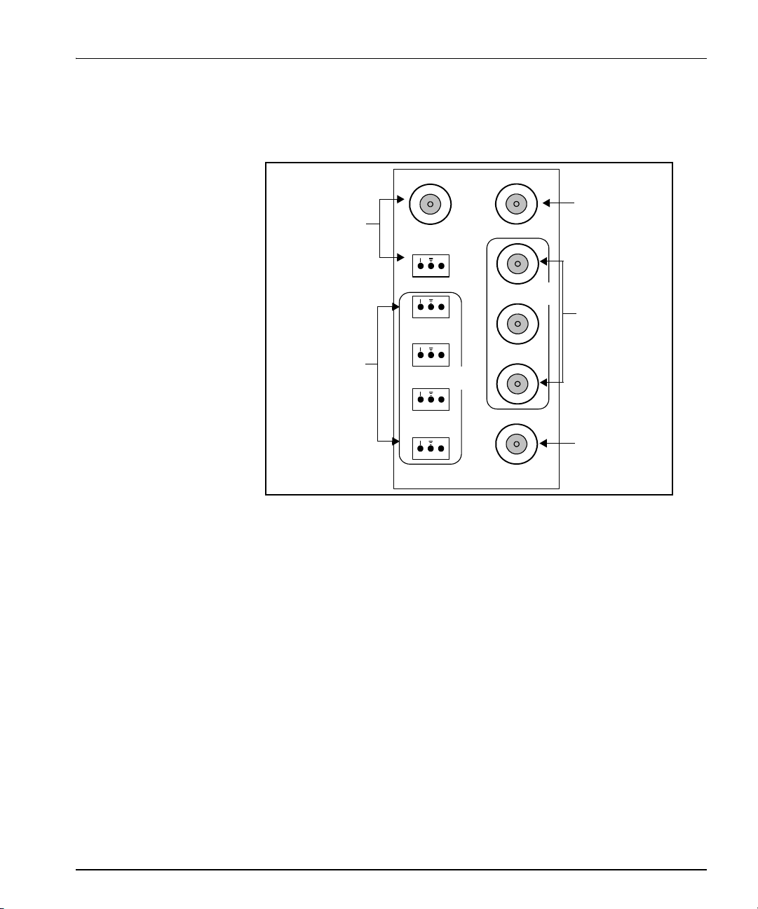
HMX6801+B4
3
4
SDI IN
DATA I/O
1
2
SDI
OUT
AUX IN
1
2
AES
IN
3
+
+
+
+
+
Reserved for
future use
Balanced AES
input channels
SDI video
outputs
SDI video
input
Reserved for
future use
Chapter 1: Introduction
Figure 1-3 shows the double-slot back connector used by the
HMX6801+B4 module when installed in an FR6802+XF frame.
HMX6801+B2/C2 and HMX6801+B4/C4 Installation and Operation Manual 7
Figure 1-3. HMX6801+B4 Back Connector
Page 22
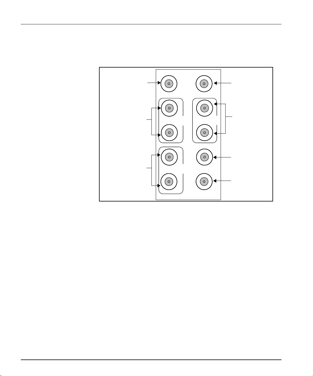
Chapter 1: Introduction
SDI IN
DATA I/O
1
2
SDI
OUT
AUX IN
AES
IN
1
2
2
1
AES
OUT
DARS IN
Reserved for
future use
Unbalanced AES
input channels
Unbalanced AES
output channels
SDI video
outputs
SDI video
input
DARS
input
Reserved for
future use
HMX6801+C2
Figure 1-4 shows the double-slot back connector used by the
HMX6801+C2 module when installed in an FR6802+XF frame.
8 HMX6801+B2/C2 and HMX6801+B4/C4 Installation and Operation Manual
Figure 1-4. HMX6801+C2 Back Connector
Page 23
HMX6801+C4
SDI IN
DATA I/O
1
2
SDI
OUT
AUX IN
AES
IN
3
4
2
1
3
Reserved for
future use
Unbalanced AES
input channels
SDI video
outputs
SDI video input
Reserved for
future use
Chapter 1: Introduction
Figure 1-5 shows the double-slot back connector used by the
HMX6801+C4 module when installed in an FR6802+XF frame.
HMX6801+B2/C2 and HMX6801+B4/C4 Installation and Operation Manual 9
Figure 1-5. HMX6801+C4 Back Connector
Page 24
Chapter 1: Introduction
Equalizer
Deserializer
input/output
Embedder
Audio processing
amplifier
SDI outputs
AES 1
AES 2
AES 3
AES 4
Serializer
input/output
Serializer
input/output
Driver 1
Driver 2
SDRAM
Clock
control
Clock
VCXOs
(B2/C2 options only)
AES
outputs
CCS control/
monitor port
(B4/C4
options only)
Processed only
SRC
SRC
SRC
SRC
Processed only
SDI input
(B2/C2 options only)
AES input
DARS input
(B4/C4 options only)
Processed only
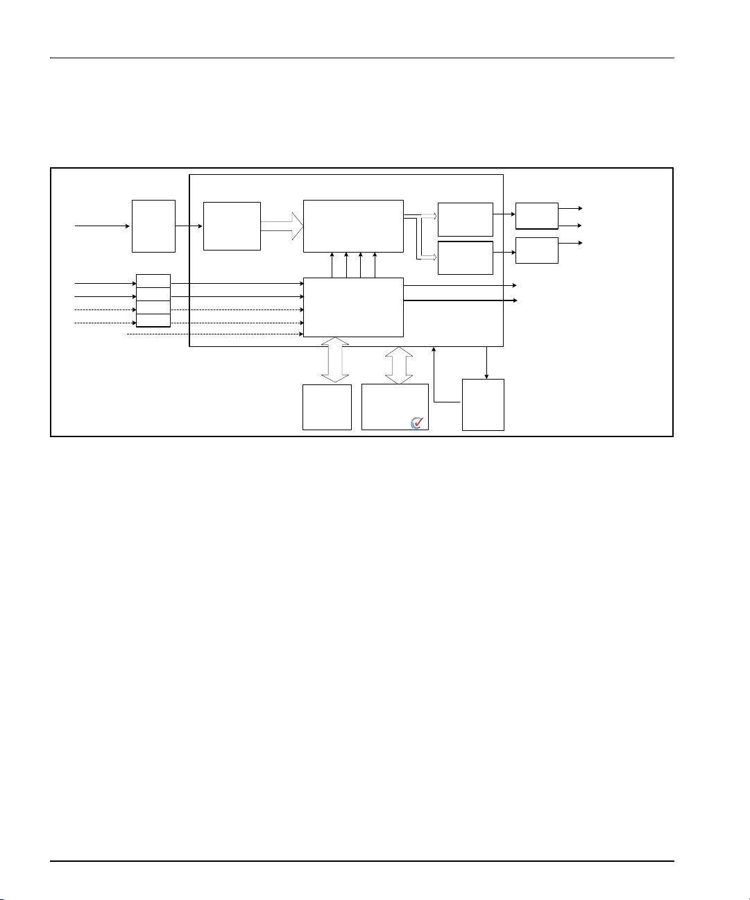
Signal Flow
Figure 1-6 shows the basic signal flow of the HMX6801+B2/C2 and
HMX6801+B4/C4 modules.
Figure 1-6. HMX6801+B2/C2 and HMX6801+B4/C4 Signal Flow Diagram
10 HMX6801+B2/C2 and HMX6801+B4/C4 Installation and Operation Manual
Page 25

Overview
Caution
Before installing this product,
read the 6800+ Series Safety
Instructions and Standards
Manual shipped with every
FR6802+ Frame Installation
and Operation Manual or
downloadable from our We b
site. This safety manual
contains important information
about the safe installation and
operation of 6800+ series
products.
Chapter 2
Installation
This chapter describes the HMX6801+B2/C2 and HMX6801+B4/C4
installation process, including the following topics:
• “Maximum 6800+ Frame Power Ratings” on page 12
• “Unpacking the Module” on page 13
• “Setting Jumpers” on page 14
• “Installing and Removing HMX6801+ Modules” on page 15
• “Upgrading HMX6801+ Firmware” on page 16
See the FR6802+ Frame Installation and Operation Manual for
information about installing and operating FR6802+ series frames and
their components.
HMX6801+B2/C2 and HMX6801+B4/C4 Installation and Operation Manual 11
Page 26

Chapter 2: Installation
Maximum 6800+ Frame Power Ratings
The power consumption for HMX6801+B2/C2 and HMX6801+B4/C4
modules is 7 W from the positive supply and 0.2 W from the negative
supply. Power consumption information is also listed in the
Specifications chapter.
Table 2-1 states the maximum allowable power ratings for 6800+
frames. Note the given maximums before installing any 6800+ modules
in your frame. HMX6801+ modules cannot be installed in frames
without fans, or in FR6802+DM and 6800/7000 series frames.
Table 2-1. Maximum Power Settings for 6800+ Frames
6800+ Frame Type
FR6802+QXF
(frame with AC or DC
power supply)
FR6802+XF
(frame with AC power
supply)
FR6802+XF
(frame with DC power
supply)
Max.
Max. Frame
Power
Dissipation
number of
Installed
HMX6801+
Modules
120 W 10 12 W
120 W 10 12 W
120 W 10 10.5 W
Max Power
Dissipation
for Two
Slots
12 HMX6801+B2/C2 and HMX6801+B4/C4 Installation and Operation Manual
Page 27

Note
Unpacking the Module
Preparing the Product for Installation
Before you install the HMX6801+B2/C2 and HMX6801+B4/C4,
perform the following:
• Check the equipment for any visible damage that may have
occurred during transit.
Contact your Customer Service
representative if parts are
missing or damaged.
• Confirm receipt of all items on the packing list. See “Checking the
Packing List” for more information.
• Remove the anti-static shipping pouch, if present, and all other
packaging material.
• Retain the original packaging materials for possible re-use.
See “Unpacking/Shipping Information” on page ix for information
about returning a product for servicing.
Chapter 2: Installation
Checking the Packing List
Table 2-2. Available Product Packages
Ordered Product Content Description
HMX6801+B2D,
HMX6801+B4D,
HMX6801+C2D, or
HMX6801+C4D
• One front module
• One back connector
• One HMX6801+B2/C2 and
HMX6801+B4/C4 Two and Four
Channel HD and SD AES Multiplexers
Installation and Operation Manual
HMX6801+B2/C2 and HMX6801+B4/C4 Installation and Operation Manual 13
Page 28
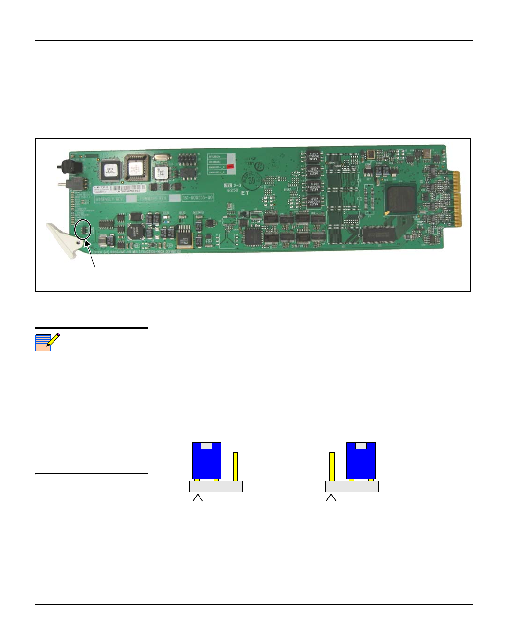
Chapter 2: Installation
REM/LOC jumper
Remote/local
Note
1 2 3 1 2 3
Remote control setting
Local control setting
Setting Jumpers
The HMX6801+B2/C2 and HMX6801+B4/C4 modules have one
jumper for remote or local control. Figure 2-1 shows the location of the
REM/LOC jumper.
Figure 2-1. Location of the REM/LOC Jumper (HMX6801+B4/C4 is shown)
Follow this procedure to set the REM/LOC jumper for either remote or
local control:
Y ou must configure modules for
local or remote operation prior
to power-up. To change the
configuration, first remove
power from the module, reset
the jumper, and then reapply
power.
The white triangle near the
jumper pins on the module
indicates pin 1.
1. Locate the REM/LOC control jumper on the module (beside the
extractor handle).
Figure 2-1 shows the standard location of the REM/LOC jumper.
2. Place a jumper on pins 1 and 2 to set the module for Remote control
or pins 2 and 3 to set the module for Local control. See Figure 2-2.
Figure 2-2. REM/LOC Settings for Remote and Local Control
See Table 1-1 "Generic 6800+ Module Features" for more information
on local/remote control jumper functionality.
14 HMX6801+B2/C2 and HMX6801+B4/C4 Installation and Operation Manual
Page 29

Caution
Chapter 2: Installation
Installing and Removing HMX6801+ Modules
The HMX6801+ modules have double-width back connectors. The
modules cannot be installed in frames without fans, or in FR6802+DM
and 6800/7000 series frames.
These modules require no specialized installation or removal
procedures. However, if you are installing both front and rear modules,
Before installing your modules,
see Table 2-1 "Maximum Power
Settings for 6800+ Frames" on
page 12.
ensure that the back module is installed first before plugging in the front
module. Likewise, ensure that the front module is unplugged from the
frame before removing the rear module. See the FR6802+ Frames
Installation and Operation Manual for information about installing and
operating an FR6802+ frame and its components.
HMX6801+B2/C2 and HMX6801+B4/C4 Installation and Operation Manual 15
Page 30
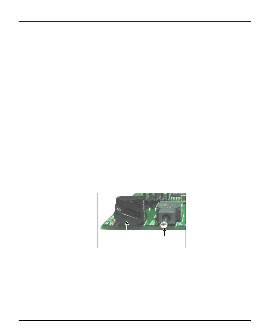
Mode select rotary
(hex) switch
Navigation toggle
switch
Chapter 2: Installation
Upgrading HMX6801+ Firmware
Firmware upgrading is a routine procedure that you must perform to
install newer versions of software on a HMX6801+ module. The
HMX6801+ module can be upgraded in Boot Loader mode only. CCS
Pilot, Co-Pilot, or Navigator software version 3.1.1 or later is required
for this procedure. The HMX6801+ must be installed in a frame that
contains or is connected to another frame that contains an ICE6800+
module.
When performing the upgrading procedure, check the appropriate
readme file to confirm which files are needed. Use care to ensure that
you upload the correct files to the HMX6801+ module.
If for some reason the upgrade fails, the module may not respond to
controls and will appear to be non-functional. In that event, follow the
procedures described in “Correcting a Failed Upgrade Procedure” on
page 20.
Follow these steps to upgrade a HMX6801+ module’s firmware:
1. Download the most recent appropriate upgrade package from our
Web site or from your CD-ROM.
2. Remove the HMX6801+ module from the 6800+ frame.
3. Set the hex switch to F.
16 HMX6801+B2/C2 and HMX6801+B4/C4 Installation and Operation Manual
Figure 3. Buttons on a Typical Card Edge
4. While pressing the Navigation toggle switch down, reinsert the
HMX6801+ module into the frame and then release the Navigation
toggle switch.
Page 31

Click Device Options
to enter T elnet and FTP
user name and
password or create
automatic backups.
Click Package Info to
view a list of the
components contained
in the ZIP file.
Chapter 2: Installation
5. Perform a Discovery operation to discover the HMX6801+
module, as described in your CCS software application manual or
online help. (If you cannot discover the HMX6801+ module using
the Discovery tool, see “Discovering Devices Using the
Drag-and-Drop Method” on page 19.)
6. From the Tools menu, select Software Upgrade.
The Software Upgrade window opens or is brought to the
foreground.
Figure 2-3. Typical Software Upgrade Tool New Transfer Tab
7. On the New Transfer tab, click Add.
The Device Selection dialog opens.
8. Select one or more HMX6801+ devices, and then click OK to close
the Add Device dialog box. When adding modules to the list, keep
in mind the following points:
• Y ou can only add one module per IP address. All modules in up
to nine frames that are connected to the same ICE6800+
module have the same IP address.
HMX6801+B2/C2 and HMX6801+B4/C4 Installation and Operation Manual 17
Page 32

Chapter 2: Installation
Note
• You can only upgrade one device type: e.g., you can add a
series of HMX6801+ modules that all reside at different IP
addresses.
The selected devices appear in the table on the New Transfer tab of
the Software Upgrade window. This table lists devices that are to
receive the upgrade package.
You can click on an individual item in the list to view
module-specific information:
• To highlight the position of a module in the Navigation
window, click Find Device.
• To check the module’s software revision numbers, etc., click
Version Info.
• To create an automatic backup of the selected module’s
firmware, click Device Options.... (Place a check beside
Software Backup and enter a file name or click Browse to
choose a new file location.)
9. Press Browse... to select the software upgrade package (ZIP file).
A standard Windows File Selection dialog opens.
Closing the Software Upgrade
window does not effect any
transfer processes that may be
running in the background.
However, if you try to log of f o r
exit the CCS software while a
transfer is underway, a
notification window will alert
you that processes are still
active and will ask if you want
to terminate these processes.
10. Choose the upgrade ZIP file on a local or network drive.
The selected file’s path name is displayed in the edit box to the left
of the Browse… button.
The extraction process on the ZIP file is handled as part of the
upgrade process. You do not need to extract the files yourself.
11. Press Submit Transfer...
A dialog box opens, requesting confirmation that you want to
proceed with the request. If you have multiple devices selected,
multiple transfer tasks are submitted—one per device.
The transfer now progresses. Y ou may close the Software Upgrade
window, continue with other tasks, or switch to the Progress tab to
view the status of the transfers.
12. Click on the Log tab and look at the Progress column to ensure that
all files have correctly updated.
13. When the update is complete, reboot the HMX6801+ mo dule by
manually pulling it out and then pushing it back into its slot in the
frame.
You cannot click Reboot Device to reboot HMX6801+ modules.
18 HMX6801+B2/C2 and HMX6801+B4/C4 Installation and Operation Manual
Page 33

Caution
Do not make changes in
this field
Enter frame IP number here
Your upgrade procedure is complete.
If for some reason the upgrade fails, the module may not respond to
controls and will appear to be non-functional. In that event, follow the
procedures described in “Correcting a Failed Upgrade Procedure” on
page 20.
Discovering Devices Using the Drag-and-Drop Method
If you cannot discover your HMX6801+ module using the Discovery
tool, use this method to discover it:
1. With your CCS software in Build mode, drag or copy and paste the
module’s device icon from the Catalog folder into the Network or
Discovery folder.
2. Right-click the device icon and then select Properties.
3. On the Device tab of the Navigation Properties box, enter the IP
address of the frame that holds the module. (See Figure 3.)
Chapter 2: Installation
Do not make changes in the last
Device ID field (located above
and to the right of the Set
Default button.)
Figure 3. Navigation Properties Box
4. In the third field, enter the slot number of the HMX6801+ module,
and then close the window.
You can now continue upgrading your HMX6801+ module’s firmware,
starting with step 3 in “Upgrading HMX6801+ Firmware” on page 16.
HMX6801+B2/C2 and HMX6801+B4/C4 Installation and Operation Manual 19
Page 34

Note
Note
Chapter 2: Installation
Correcting a Failed Upgrade Procedure
Firmware upgrades may fail in the event of network interruptions,
power failures, or if files were sent to the wrong 6800+ module.
These problems can be corrected by re-installing the firmware while in
Boot Loader mode, as described below. When you are performing this
procedure, check the appropriate readme file to confirm which files are
needed. Use care to ensure that you upload the correct files to the
HMX6801+ module.
Follow these steps to upgrade the firmware in Boot Loader mode:
1. Download the most recent appropriate upgrade package from our
Web site or from your CD-ROM, and then unzip the upgrade
To successfully upgrade the
firmware, you must follow these
steps in the exact sequence
described.
package.
2. If the HMX6801+ module has not been discovered by your CCS
software application, enter Build mode, and then discover your
module using the drag-and-drop method. See “Discovering Devices
Using the Drag-and-Drop Method” on page 19 for more
information.
3. Double-click the device icon for the HMX6801+ module.
The Configuration... box opens. On the File Transfer tab, the
/frameX/slotY (where X is the frame number and Y is the slot
number) directory appears in the Select the device directory to
transfer to: field.
4. Click Add, and in the Add Upgrade Files box, browse, select the
HMX6801+ module’s upgrade package and then click OK.
You must delete unwanted files
in the Add upgrade files for
transfer to device: field before
transferring the files. Otherwise,
the upgrading procedure will
fail.
5. On the File Transfer tab, choose the file you wish to upgrade and
then click OK.
6. Click Perform Transfer and then click Yes.
This may take several minutes.
7. When the message File transfer to device succeeded appears in
the status bar, reboot the HMX6801+ module by manually pullling
it out and then pushing it back into its slot in the frame.
You cannot click Reboot Device to reboot HMX6801+ modules.
Your upgrade procedure is complete.
20 HMX6801+B2/C2 and HMX6801+B4/C4 Installation and Operation Manual
Page 35

Overview
Chapter 3
Operation
This chapter describes how to operate the HMX6801+B2/C2 and
HMX6801+B4/C4 using card-edge controls only. See the following
documents for information on how to operate this product remotely:
• + Pilot Lite User Manual for serial interface
• CCS Pilot, CoPilot, Navigator, or NUCLEUS Network Control,
LCP-3901-1U/RCP-CCS-1U Local and Remote Control Panel
manuals for Ethernet interface
The following topics are discussed in this chapter:
• “Operating Notes” on page 22
• “Audio Processing Information” on page 23
• “Non-PCM Processing” on page 32
• “Changing Parameter Settings” on page 38
• “Setting HMX6801+B2/C2 and HMX6801+B4/C4 Control
Parameters” on page 40
• “LEDs and Alarms” on page 61
HMX6801+B2/C2 and HMX6801+B4/C4 Installation and Operation Manual 21
Page 36

Chapter 3: Operation
Operating Notes
When setting the control parameters on the HMX6801+B2/C2 and
HMX6801+B4/C4, observe the following:
• If you make changes to certain parameters, other related parameters
may also be affected. See the section “Cross-Functional Parameter
Changes” on page 33 for more information.
• When you change a parameter, the effect is immediate. However,
the module requires up to 20 seconds to save the latest change.
After 20 seconds, the new settings are saved and will be restored if
the module loses power and must be restarted.
• When you set the Factory Recall parameter to Yes, the module
takes several seconds to reset all of the parameters to their default
settings.
• Terminate any unused coaxial output connectors with a 75Ω
terminator.
• Reclocked/processed output selection for Output 1 is not currently
supported. Output 1 is a processed-only output.
See the following topics for more operational information:
• “Audio Embedding Modes” on page 23
• “Audio Embedding Errors” on page 28
• “Audio Output Channel Status (OutxxStat)” on page 28
• “Input Channel V-Bit Feedback (InxxVbitFb)” on page 29
• “Audio Embedding Channel Source Selection” on page 29
• “Input Audio Rate” on page 30
• “Channel Summing (PCM Processing only)” on page 30
• “Non-PCM Processing” on page 32
22 HMX6801+B2/C2 and HMX6801+B4/C4 Installation and Operation Manual
Page 37

Audio Processing Information
Audio Embedding Modes
The audio embedder component in the HMX6801+B2/C2 and
HMX6801+B4/C4 is composed of several smaller subcomponent
blocks:
• One ancillary data stripper (ADS)
• Two audio embedding subcomponents
The first subcomponent is an ancillary data stripper (ADS). This block
removes all ancillary data packets in the input SDI stream, prior to
embedding.
Following the ADS block are two separate audio-embedding
subcomponents. Each subcomponent has the ability to operate on only
one audio group, either appending or overwriting a predetermined
group onto the SDI stream.
The audio embedding modes are G1EmbMode and G2EmbMode.
Table 3-1 briefly describes the Off, Append, OverWrt, and Auto
options available from each of the embedding modes.
Chapter 3: Operation
Table 3-1. Embedding Mode Options
Options Description
Off Disables embedding of the selected audio group
Append Attempts to insert the audio data and control packets
immediately following the last existing audio data/control
packet in the horizontal ancillary region
(This setting is valid only if the audio group to be
embedded does not already exist.
See Figure 3-1 on page 25 and Figure 3-2 on page 26 for
more information on Append embedding mode.
HMX6801+B2/C2 and HMX6801+B4/C4 Installation and Operation Manual 23
Page 38

Chapter 3: Operation
Table 3-1. Embedding Mode Options (Continued)
Options Description
OverWrt Attempts to overwrite existing audio data and control
packets of the same group number with the new audio data
(This setting is valid only if the audio group to be
embedded already exists.)
In this setting, if the new sample distribution does not
exactly match the existing audio data packet sample
distribution, the embedder will mark some audio data
packets for deletion (DID word will be set to 180h).
To avoid sample distribution issues, enable the ADS
Clean feature.
See Figure 3-3 on page 27 for more information on
OverWrt embedding mode.
Auto Attempts first to overwrite existing audio data and control
packets of the same audio group number; failing that,
appends the new audio data and control packets
immediately following the last existing audio data/control
packet
Refer to the G1Exists, G2Exists, G3Exists, and G4Exists
parameters to determine what audio groups are already
present in the incoming SDI signal.
24 HMX6801+B2/C2 and HMX6801+B4/C4 Installation and Operation Manual
Page 39

Append Embedding
EAV
ADS before embedding
EAV
ADS after embedding group
Group 1
ADS before embedding
Other
auxilliary data
A
EAV
Other
auxilliary data
B
ADS after embedding group
Group 1
EAV
Other
aux illiary data
A
Other
auxilliary data
B
ADS before embedding
Pre-existing
Group 1
EAV
EAV
Pre-existing
Group 1
Result: Error is returned
Chapter 3: Operation
Figure 3-1. Append Embedding Mode, Part 1
HMX6801+B2/C2 and HMX6801+B4/C4 Installation and Operation Manual 25
Page 40

Chapter 3: Operation
ADS after embedding group 2
ADS before embedding
EAV
Other
auxillary
data
Other
auxillary
data
Other
auxillary
data
ADS before embedding
EAV
Group 2
EAV Group 1
Group 2
EAV
ADS before embedding
Group 1
ADS after attempting to embed group 1
EAV
Result: Error is returned
Other
auxillary
data
Other
auxillary
data
Other
auxillary
data
ADS after embedding group 1
Group 1
EAV
Group 2
Figure 3-2. Append Embedding Mode, Part 2
26 HMX6801+B2/C2 and HMX6801+B4/C4 Installation and Operation Manual
Page 41

Overwrite Embedding
ADS before embedding
EAV
EAV
ADS before embedding
other
auxilliary data
A
other
auxilliary data
B
ADS after embedding group 1
(with overwrite group specified as Group 1)
Group 1
EAV
ADS before embedding
Pre-existing Group 1
EAV
ADS after attempting to embed group 1
EAV
other
auxilliary data
A
other
auxilliary data
B
Result: Error is returned
EAV
ADS after attempting to embed group 1
Result: Error is returned
Chapter 3: Operation
Figure 3-3. OverWrt Embedding Mode
HMX6801+B2/C2 and HMX6801+B4/C4 Installation and Operation Manual 27
Page 42

Chapter 3: Operation
Audio Embedding Errors
Table 3-2 describes G1-2AppErr and G1-2OvrWtErr audio
embedding errors.
Table 3-2. Audio Embedding Error Descriptions
Error Description
G1-2AppErr Occurs if the embedder is set to Append mode for a
G1-2OvrWtErr Occurs if the embedder is set to Overwrite mode for a
To avoid embedding errors, follow these guidelines:
particular audio group, but that audio group already exists
in the incoming SDI signal
In this case, the embedder will not embed another audio
data and control packet of the same audio group, as this
will result in incorrect audio sample distribution.
particular audio group, but that audio group does not exist
in the incoming SDI signal
• Set the embedding mode to Auto. If the group is present, it will be
overwritten; if it is not present, it will be appended. The overwrite
and append errors are actually warnings that the desired operation is
not being performed.
• In SD-SDI mode do not overwrite embedded groups of 20-bit audio
samples with groups of 24-bit audio samples. The required
extended data packet information appended to that group ma y
overwrite a pre-existing audio group. For 24-bit audio embedding,
use the ADS Clean feature provided.
Audio Output Channel Status (OutxxStat)
Table 3-3 describes the three parameter options for audio output
channel level status.
Table 3-3. Audio Output Channel Level Status Options
Options Description
Peak Audio output level has reached a level of 0 dBFS.
Silence Audio output level is lower than -96 dBFS.
Normal Audio output level is between the Peak and Silence
threshold levels.
28 HMX6801+B2/C2 and HMX6801+B4/C4 Installation and Operation Manual
Page 43

Note
Note
Input Channel V-Bit Feedback (InxxVbitFb)
Table 3-4 describes the two parameter options for input channel V-bit
(Validity bit) status.
Table 3-4. Input Channel V-Bit (Validity-Bit) Status Options
Option Description
On V-bit of the incoming audio channel set to 1; indicates that
the audio sample word data is invalid (or possibly
compressed audio) and is not suitable for D/A conversion
Off V-bit of the incoming audio channel set to 0; indicates that
the audio sample word data is valid and is suitable for D/A
conversion
Audio Embedding Channel Source Selection
On the HMX6801+B2/C2 and HMX6801+B4/C4 modules, the
following audio source selections are available for each OutxSrc
Items marked with an “*” apply
to HMX6801+B4/C4 options
only.
Out1-4Src output channels
correspond to Embedder 1 and
Out5-7Src channels correspond
to Embedder 2.
parameter:
• AES 1A
• AES 1B
• AES 2A
• AES 2B
• AES 3A*
• AES 3B*
• AES 4A*
• AES 4B*
• AES 1 Sum
• AES 2 Sum
• AES 3 Sum*
• AES 4 Sum*
• Test Tone 1 (750 Hz, -20 dBFS)
• Test Tone 2 (1.5 kHz, -20 dBFS)
• Test Tone 3 (3 kHz, -20 dBFS)
• Test Tone 4 (6 kHz, -20 dBFS)
Chapter 3: Operation
HMX6801+B2/C2 and HMX6801+B4/C4 Installation and Operation Manual 29
Page 44

Chapter 3: Operation
Input Audio Rate
If any of the AES input channels are of a Non-PCM format, then a
channel summation (AES × Sum) of the channel for any OutxSrc is not
a valid selection. For example, if AES 1A or AES 1B (or both) are
Non-PCM, then AES 1 SUM is not a valid selection for any
OutxSrc parameter. See “Non-PCM Processing” on page 32 for the
handling of Non-PCM input channels.
When embedding audio in PCM mode (OutxxFrmt = PCM or
OutxxFrmt = Auto and OutxxFrmFb = PCM), the input audio
sample rate may be from 32 kHz to 96 kHz. This input audio will be
sample rate converted to 48 kHz prior to embedding in the HD video
signal; as well, the embedder will indicate 48 kHz in the “Rate” word of
the audio control packet for each embedded audio group.
When embedding audio in Non-PCM mode (OutxxFrmt = Non-PCM
or OutxxFrmt = Auto and OutxxFrmFb = Non-PCM), the input
audio sample rate must be 48 kHz and frequency locked to the source
video. In this scenario, the sample rate conversion function is bypassed
and the embedder will indicate 48 kHz in the “Rate” word of the audio
control packet for each embedded audio group.
Channel Summing (PCM Processing only)
If you select AES 1 Sum, AES 2 Sum, AES 3 Sum, or AES 4 Sum as
the source, the result is the sum of the two parts of the channel divided
by two (the mean average).
For example, AES 1 Sum = (AES 1A + AES 1B) ÷ 2
Therefore, the stereo signal is averaged, creating a monaural signal. See
Figure 3-4 on page 3 1 for an illustration of this process.
30 HMX6801+B2/C2 and HMX6801+B4/C4 Installation and Operation Manual
Page 45

750 Hz
1.5 kHz
3 kHz
AES4
Sum
(A+B)/2
AES3
Sum
(A+B)/2
AES2
Sum
(A+B)/2
AES1
Sum
(A+B)/2
.
.
.
.
.
.
AES1
AES2
AES3
AES4
AES1
AES2
AES3
AES4
6 kHz
Test Tone 1
Test Tone 3
Test Tone 2
Test Tone 4
Out01
Out08
Out03
Out02
AES 1A
AES 1A
AES 1B
AES 2A
AES 2B
AES 3A
AES 3B
AES 4A
AES 4B
AES 1B
AES 2A
AES 2B
AES 3A
AES 3B
AES 4A
AES 4B
Chapter 3: Operation
Figure 3-4. PCM Processing of the Audio Mux Signal
HMX6801+B2/C2 and HMX6801+B4/C4 Installation and Operation Manual 31
Page 46

Chapter 3: Operation
Note
Non-PCM Processing
Compressed non-PCM audio signals cannot be summed and averaged
out. Therefore, if you select one of these options, the sources that
appear in the Out01Src to Out08Src parameters are arbitrarily matched
odd/even to left/right.
Example:
AES 1A and AES 1B inputs are of a non-PCM format, and AES 1 Sum
is selected for the Out01Src and Out02Src parameters. Since the
Non-PCM channels cannot be summed and averaged, then the output
channel assignments are as follows:
• Out01Src is assigned AES 1A (matched Odd number to Left
channel)
• Out02Src is assigned AES 1B (matched Even number to Right
channel)
When channels are operating in Non-PCM mode (for example,
compressed audio such as Dolby-E mode), the following parameters are
These parameters are enabled
for channels operating in PCM
mode.
disabled for the associated channel:
• Gain (forced to 0 dB)
• Invert (forced to No)
• Dithering (forced to None)
• Word Length (forced to 24-bits)
See “Cross-Functional Parameter Changes” on page 33 for full
parameter descriptions.
When operating an output channel in Non-PCM mode, the sample rate
conversion function of the associated input AES channel is bypassed.
32 HMX6801+B2/C2 and HMX6801+B4/C4 Installation and Operation Manual
Page 47

Chapter 3: Operation
Cross-Functional Parameter Changes
When you configure certain parameters, you force a change in other
associated parameters. Table 3-5 describes those parameters affected by
other option selections. Note that the forced setting (center column)
takes effect before the identified parameter (right column) becomes
enabled/disabled.
Table 3-5. Cross-Functional Parameters
Condition Forced Setting Enabled/Disabled Parameters
Output Ch01 Format = Non-PCM
or
Output Ch01 Format = Auto and
Out Ch01 Format Fb = Non-PCM
Output Ch01 Format = PCM
or
Output Ch01 Format = Auto and
Out Ch01 Format Fb = PCM
Output Ch02 Format = Non-PCM
or
Output Ch02 Format = Auto and
Out Ch02 Format Fb = Non-PCM
Output Ch02 Format = PCM
or
Output Ch02 Format = Auto and
Out Ch02 Format Fb = PCM
Output Ch03 Format = Non-PCM
or
Output Ch03 Format = Auto and
Out Ch03 Format Fb = Non-PCM
Output Ch03 Format = PCM
or
Output Ch03 Format = Auto and
Out Ch03 Format Fb = PCM
Output Ch04 Format = Non-PCM
or
Output Ch04 Format = Auto and
Out Ch04 Format Fb = Non-PCM
• Output Ch01 Gain = 0 dB
• Output Ch01 Invert = No
• Output Ch02 Gain = 0 dB
• Output Ch02 Invert = No
• Output Ch03 Gain = 0 dB
• Output Ch03 Invert = No
• Output Ch04 Gain = 0 dB
• Output Ch04 Invert = No
• Output Ch01 Gain = Disabled
• Output Ch01 Invert = Disabled
• Output Ch01 Gain = Enabled
• Output Ch01 Invert = Enabled
• Output Ch02 Gain = Disabled
• Output Ch02 Invert = Disabled
• Output Ch02 Gain = Enabled
• Output Ch02 Invert = Enabled
• Output Ch03 Gain = Disabled
• Output Ch03 Invert = Disabled
• Output Ch03 Gain = Enabled
• Output Ch03 Invert = Enabled
• Output Ch04 Gain = Disabled
• Output Ch04 Invert = Disabled
HMX6801+B2/C2 and HMX6801+B4/C4 Installation and Operation Manual 33
Page 48

Chapter 3: Operation
Table 3-5. Cross-Functional Parameters (Continued)
Condition Forced Setting Enabled/Disabled Parameters
Output Ch04 Format = PCM
or
Output Ch04 Format = Auto and
Out Ch04 Format Fb = PCM
Output Ch05 Format = Non-PCM
or
Output Ch05 Format = Auto and
Out Ch05 Format Fb = Non-PCM
Output Ch05 Format = PCM
or
Output Ch05 Format = Auto and
Out Ch05 Format Fb = PCM
Output Ch06 Format = Non-PCM
or
Output Ch06 Format = Auto and
Out Ch06 Format Fb = Non-PCM
Output Ch06 Format = PCM
or
Output Ch06 Format = Auto and
Out Ch06 Format Fb = PCM
Output Ch07 Format = Non-PCM
or
Output Ch07 Format = Auto and
Out Ch07 Format Fb = Non-PCM
Output Ch07 Format = PCM
or
Output Ch07 Format = Auto and
Out Ch07 Format Fb = PCM
Output Ch08 Format = Non-PCM
or
Output Ch08 Format = Auto and
Out Ch08 Format Fb = Non-PCM
Output Ch08 Format = PCM
or
Output Ch08 Format = Auto and
Out Ch08 Format Fb = PCM
• Output Ch05 Gain = 0 dB
• Output Ch05 Invert = No
• Output Ch06 Gain = 0 dB
• Output Ch06 Invert = No
• Output Ch07 Gain = 0 dB
• Output Ch07 Invert = No
• Output Ch08 Gain = 0 dB
• Output Ch08 Invert = No
• Output Ch04 Gain = Enabled
• Output Ch04 Invert = Enabled
• Output Ch05 Gain = Disabled
• Output Ch05 Invert = Disabled
• Output Ch05 Gain = Enabled
• Output Ch05 Invert = Enabled
• Output Ch06 Gain = Disabled
• Output Ch06 Invert = Disabled
• Output Ch06 Gain = Enabled
• Output Ch06 Invert = Enabled
• Output Ch07 Gain = Disabled
• Output Ch07 Invert = Disabled
• Output Ch07 Gain = Enabled
• Output Ch07 Invert = Enabled
• Output Ch08 Gain = Disabled
• Output Ch08 Invert = Disabled
• Output Ch08 Gain = Enabled
• Output Ch08 Invert = Enabled
34 HMX6801+B2/C2 and HMX6801+B4/C4 Installation and Operation Manual
Page 49

Chapter 3: Operation
Parameter Availability based on Operating Mode
Depending on whether the operating mode is HD or SD, some
parameters will be enabled and some disabled. The HD parameters will
apply when SdiStdSet is set to one of the HD operating modes, or when
the SdiStdSet is set to Auto and SdiStdFdbk is one of the HD operating
modes. The SD parameters will apply when SdiStdSet is set to either
SD 525 or SD 625, or the SdiStdSet is set to Auto and SdiStdFdbk is SD
525 or SD 625.
Table 3-6. Parameter Availability Based on Operating Mode
Condition
HD Operating Mode:
• 1035i/30
• 1035i/29.97
• 1080i/25 (295M)
• 1080i/30
• 1080i/29.97
• 1080i/25
• 1080p/30
• 1080p/29.97
• 1080p/25
• 1080p/24
• 1080p/23.98
• 720p/60
• 720p/59.94
• 720p/50
SDI Operating Mode:
• SD 525
• SD 625
Enabled
Parameters
• YCrcErrCnt
• YCrcErrClr
• CCrcErrCnt
• CCrcErrClr
•EdhPrsnt
•EdhErrCnt
•EdhErrClr
Disabled
Parameters
•EdhPrsnt
•EdhErrCnt
•EdhErrClr
• YCrcErrCnt
• YCrcErrClr
• CCrcErrCnt
• CCrcErrClr
HMX6801+B2/C2 and HMX6801+B4/C4 Installation and Operation Manual 35
Page 50

Chapter 3: Operation
ADS Clean Parameter
Depending on the setting of the ADSClean parameter, the EMB1Mode
and EMB2Mode parameters will have different options.
Table 3-7. ADS Clean Parameter
Channel Dithering
ADSClean state
Yes
No
When any audio output channel is of a Non-PCM format
(Output Chxx Format=Non-PCM or Output Chxx Format=Auto
and Out Chxx Format Fb=Non-PCM), the Dithering feature for that
channel pair (1-2, 3-4, etc.) is disabled, even if only one channel of the
pair is Non-PCM. Both channels in the pair must be of a PCM format
for the Dithering feature for that channel pair to be re-enabled.
For example, if Output Ch01 Format is set to Non-PCM (or Output
Ch01 Format=Auto and Out Ch01 Format Fb=Non-PCM), then
output channel pair 01-02 has dithering disabled (Out 01-02 Dithr
Mode is set to None and the parameter is disabled), even if Output
Ch02 Format is PCM. If both Output Ch01 Format and Output
Ch02 Format are changed to PCM, then the Out 01-02 Dithr Mode
parameter is re-enabled.
EMB1Mode and
EMB2Mode Options
•Off
• Append
•Off
• Append
• OverWrt
• Auto
36 HMX6801+B2/C2 and HMX6801+B4/C4 Installation and Operation Manual
Page 51

Channel Word Length
If in HD mode, the default value for all ChXX-XXWordLen
parameters is 24-bits. In SD mode, it is 20 bits.
In SD mode if at least one channel is set to 24-bits, the corresponding
embedder will enable 24-bits embedding.
Channel Fade Rate
The channel fade rate is a single control for all output channels. This
feature is only applied to output channels operating in PCM format. It is
automatically disabled for individual output channels operating in
Non-PCM format.
Chapter 3: Operation
HMX6801+B2/C2 and HMX6801+B4/C4 Installation and Operation Manual 37
Page 52

Note
Chapter 3: Operation
Changing Parameter Settings
Follow these steps to change the HMX6801+B2/C2 and
HMX6801+B4/C4 parameter settings:
1. Rotate the mode select rotary switch (hex switch) to “0.”
2. Once the hex switch is set to “0,” toggle the navigation switch up or
down to select a bank.
V iew the three control LEDs next to the navigation toggle switch to
see which bank is currently selected.
Table 3-8. Selected Bank as Indicated by Control LEDs
Bank Select LED 1
(first top LED)
Off Off Off 0
On Off Off 1
Off On Off 2
On On Off 3
Off Off On 4
On Off On 5
OffOnOn6
On On On 7
Bank Select LED 2
(second top LED)
Bank Select LED 3
(third top LED)
Bank Number
See Table 3-9 on page 41 to view the various banks, hex switch
positions, and corresponding parameter options and values.
3. Rotate the hex switch to the parameter number (1 to 9) or letter
(A to F) of the option you want to set.
4. Toggle the navigation switch to select and set the value of the
chosen parameter.
The manufacturer recommends
that you use the available 6800+
software control options
(serial/local or Ethernet/remote)
to aid in viewing, setting, and
confirming parameter values.
5. Rotate the hex switch to another parameter number/letter in the
current bank, and then repeat step 4.
or
Rotate the hex switch to “0” again to select a different bank, and
then repeat steps 3 and 4.
38 HMX6801+B2/C2 and HMX6801+B4/C4 Installation and Operation Manual
Page 53

Recalling Default Parameter Settings
Table 3-9 "Parameter Options—HMX6801+B2/C2 Modules" describes
all of the parameter settings for the HMX6801+B2/C2 and
HMX6801+B4/C4 modules, including the original factory defaults. To
return this module to its default settings, you can either reset each
parameter individually, or do a global recall following this procedure:
1. Rotate the hex switch to “0.”
2. Toggle the navigation switch to the bank number “0.”
Use the control LEDs to verify which bank you have selected, or
use an available 6800+ software control option (serial/local or
Ethernet/remote) to aid in confirming your bank selection.
3. Rotate the hex switch to the global recall parameter “F.”
4. Toggle the navigation switch to “On.”
Use an available 6800+ software control option to aid in viewing,
setting, and confirming the parameter value.
Chapter 3: Operation
Reading Software and Hardware Versions
The current software and hardware version of your HMX6801+B2/C2
and HMX6801+B4/C4 module can only be viewed using a
CCS-enabled control panel or a CCS software application, such as Pilot
or + Pilot Lite. See your NUCLEUS Network Control Panel,
LCP-3901-1U and RCP-CCS-1U Local, and Remote Control Panel
Installation and Operation Manuals, CCS software application user
manual, or CCS software application online help for information on
viewing software and hardware version numbers.
HMX6801+B2/C2 and HMX6801+B4/C4 Installation and Operation Manual 39
Page 54

Note
Note
Chapter 3: Operation
Setting HMX6801+B2/C2 and HMX6801+B4/C4 Control Parameters
The following table lists all of the available parameters and options for
the HMX6801+B2/C2 and HMX6801+B4/C4. All parameters clip
The sequence of options listed
in the Options column mirrors
the sequence achieved when
you move the Navigation
Toggle switch up.
unless otherwise indicated.
The On/Off combinations of the control LEDs on the card-edge indicate
the active bank number. See “Changing Parameter Settings” on page 38
for more information.
All parameters clip unless
otherwise indicated.
Parameters designated as
read-only [RO] are only
available from a remote CCS
software control application
such as Pilot or Navigator.
Legend
Bold option = Indicates that this is the default setting for the parameter
[RO] = Indicates that parameters are read-only/feedback, and cannot be
used to select controls
Superscript number
(1)
= Indicates that a footnote follows the table
* = Indicates that this parameter/option is only available on the
HMX6801+B2 module version
40 HMX6801+B2/C2 and HMX6801+B4/C4 Installation and Operation Manual
Page 55

Table 3-9. Parameter Options—HMX6801+B2/C2 Modules
Chapter 3: Operation
Bank, Rotary
Switch
0, 1 SDI IP Video Std
0, 2 Y CRC Err Cnt
0, 3 C CRC Err Cnt
0, 4 EDH Err Clr Clears the EDH error counter
0, 5 DARS Input Type Selects the type of DARS input
0, 6 ADS Clean Cleans the Ancillary Data Space
Parameter
Name
Set
Clear
Clear
Function Options
Selects the SDI input video signal
standard
Clears the luminance CRC error
counter
Clears the chrominance CRC error
counter
(balanced / unbalanced)
prior to audio embedding
• Auto
• 1035I30
• 1035I29.97
• 1080I25 (295M)
• 1080I30
• 1080I29.97
• 1080I25
• 1080P30
• 1080P29.97
• 1080P25
• 1080P24
• 1080P23.98
• 720P60
• 720P59.94
• 720P50
• SD-525
• SD-625
• No
•Yes
• No
•Yes
• No
•Yes
• Balanced
• Unbalanced
• No
•Yes
HMX6801+B2/C2 and HMX6801+B4/C4 Installation and Operation Manual 41
Page 56

Chapter 3: Operation
Table 3-9. Parameter Options—HMX6801+B2/C2 Modules(Continued)
Bank, Rotary
Switch
0, 7 Embed Group
0, 8 Embedder 1
0, 9 Embedder 2
0, A Input Ch1A
0, B Input Ch1B Delay Adjusts delay for input channel
Parameter
Name
1
Select
Mode
Mode
Delay
Function Options
Selects the audio groups to be
embedded
Selects the embedding mode for the
first embedder
Selects the embedding mode for the
second embedder
Adjusts delay for input channel
AES 1A
AES 1B
• 1 & 2
•1 & 3
•1 & 4
•2 & 3
•2 & 4
•3 & 4
•Off
• Append
• OverWrt
• Auto
• Off
• Append
• OverWrt
• Auto
0.0 to 1320.0 msec
0.0 to 1320.0 msec
0, C Input Ch2A
Delay
0, D Input Ch2B Delay Adjusts delay for input channel
0, E V-Bit Mute
Enable
0, F Factory Recall Recalls the factory settings
42 HMX6801+B2/C2 and HMX6801+B4/C4 Installation and Operation Manual
Adjusts delay for input channel
AES 2A
AES 2B
Enables audio channel muting upon
detection of an incoming set V-bit
0.0 to 1320.0 msec
0.0 to 1320.0 msec
• No
•Yes
• Off
•On
Page 57

Table 3-9. Parameter Options—HMX6801+B2/C2 Modules(Continued)
Chapter 3: Operation
Bank, Rotary
Switch
1, 1 Out 01 Source
1, 2 Out 02 Source
1, 3 Out 03 Source
Parameter
Name
Select
Select
Select
Function Options
Selects the source for output
channel 01
Selects the source for output
channel 02
Selects the source for output
channel 03
• AES 1A
• AES 1B
• AES 2A
• AES 2B
•AES 1 Sum
•AES 2 Sum
• TstTone 1
• TstTone 2
• TstTone 3
•TstTone 4
• AES 1A
• AES 1B
• AES 2A
• AES 2B
•AES 1 Sum
•AES 2 Sum
• TstTone 1
• TstTone 2
• TstTone 3
•TstTone 4
• AES 1A
• AES 1B
• AES 2A
• AES 2B
•AES 1 Sum
•AES 2 Sum
• TstTone 1
• TstTone 2
• TstTone 3
•TstTone 4
HMX6801+B2/C2 and HMX6801+B4/C4 Installation and Operation Manual 43
Page 58

Chapter 3: Operation
Table 3-9. Parameter Options—HMX6801+B2/C2 Modules(Continued)
Bank, Rotary
Switch
1, 4 Out 04 Source
1, 5 Out 05 Source
1, 6 Out 06 Source
Parameter
Name
Select
Select
Select
Function Options
Selects the source for output
channel 04
Selects the source for output
channel 05
Selects the source for output
channel 06
• AES 1A
• AES 1B
• AES 2A
• AES 2B
•AES 1 Sum
•AES 2 Sum
• TstTone 1
• TstTone 2
• TstTone 3
•TstTone 4
• AES 1A
• AES 1B
• AES 2A
• AES 2B
•AES 1 Sum
•AES 2 Sum
• TstTone 1
• TstTone 2
• TstTone 3
•TstTone 4
• AES 1A
• AES 1B
• AES 2A
• AES 2B
•AES 1 Sum
•AES 2 Sum
• TstTone 1
• TstTone 2
• TstTone 3
•TstTone 4
44 HMX6801+B2/C2 and HMX6801+B4/C4 Installation and Operation Manual
Page 59

Table 3-9. Parameter Options—HMX6801+B2/C2 Modules(Continued)
Chapter 3: Operation
Bank, Rotary
Switch
1, 7 Out 07 Source
1, 8 Out 08 Source
1, 9 AES Out 1
1, A AES Out 2
1, B to
2, 3
Parameter
Name
Select
Select
Source Sel
Source Sel
Output Ch01
Format
to
Output Ch08
Format
Function Options
Selects the source for output
channel 07
Selects the source for output
channel 08
Selects the source for AES output 1
Selects the source for AES output 2
Selects the AES format for output
channels 01 to 08
• AES 1A
• AES 1B
• AES 2A
• AES 2B
•AES 1 Sum
•AES 2 Sum
• TstTone 1
• TstTone 2
• TstTone 3
•TstTone 4
• AES 1A
• AES 1B
• AES 2A
• AES 2B
•AES 1 Sum
•AES 2 Sum
• TstTone 1
• TstTone 2
• TstTone 3
•TstTone 4
• Emb1 Pair1
•Emb1 Pair2
•Emb2 Pair1
•Emb2 Pair2
•Emb1 Pair1
• Emb1 Pair2
•Emb2 Pair1
•Emb2 Pair2
•PCM
•Non-PCM
• Auto
2
HMX6801+B2/C2 and HMX6801+B4/C4 Installation and Operation Manual 45
Page 60

Chapter 3: Operation
Table 3-9. Parameter Options—HMX6801+B2/C2 Modules(Continued)
Bank, Rotary
Switch
2, 4 to
2, B
2,C to
3, 4
3,5 to
3, C
3, D Out 01-02 Dithr
3, E Out 03-04 Dithr
3, F Out 05-06 Dithr
4, 1 Out 07-08 Dithr
4, 2 Out Ch01-02
4, 3 Out Ch03-04
4, 4 Out Ch05-06
Parameter
Name
Output Ch01
Gain
to
Output Ch08
Gain
Output Ch01
Invert
to
Output Ch08
Invert
Output Ch01
Mute
to
Output Ch08
Mute
Mode
Mode
Mode
Mode
Word Len
Word Len
Word Len
Function Options
Adjusts gain for output channels 01
to 08
Inverts control for output channels
01 to 08
Enables muting for output channels
01 to 08
Enables dithering for output
channel pair 01-02
Enables dithering for output
channel pair 03-04
Enables dithering for output
channel pair 05-06
Enables dithering for output
channel pair 07-08
Selects the word length for output
audio channel pair 01-02
Selects the word length for output
audio channel pair 03-04
Selects the word length for output
audio channel pair 05-06
-18.0 to 18.0 dB (0.0)
• No
•Yes
• Off
•On
• None
•On
• None
•On
• None
•On
• None
•On
• 24 bits
• 20 bits
• 16 bits
• 24 bits
• 20 bits
• 16 bits
• 24 bits
• 20 bits
• 16 bits
46 HMX6801+B2/C2 and HMX6801+B4/C4 Installation and Operation Manual
Page 61

Table 3-9. Parameter Options—HMX6801+B2/C2 Modules(Continued)
Chapter 3: Operation
Bank, Rotary
Switch
4, 5 Out Ch07-08
4, 6 Fade Rate Controls the rate of fading when
1 When group numbers are assigned to the embedders, Embedder1 is always assigned a lower group
number: i.e. if Embedder Group Selection (EmbGrpSel) is set to 2&4, Embedder 1 is assigned to
group 2 and Embedder 2 is assigned to group 4.
2 Use Non-PCM channel format when passing compressed audio such as Dolby-E.
Parameter
Name
Word Len
Function Options
Selects the word length for output
audio channel pair 07-08
channels are swapped or muted
• 24 bits
• 20 bits
• 16 bits
0.0 to 10.0 sec (1.0)
HMX6801+B2/C2 and HMX6801+B4/C4 Installation and Operation Manual 47
Page 62

Chapter 3: Operation
Table 3-10. HMX6801+B2/C2 Read-Only Parameters—Remote Control Only
Bank,
Rotary
Parameter Name Function Options
Switch
1
[RO]
[RO] SDI IP Video Present Reports the presence of the SDI input
SDI IP Video Std Fb Reports the detected SDI input video
signal standard
video signal
• Auto
• SD 525
• SD 625
• 1035I30
• 1035I29.97
• 1080I25 (295M)
• 1080I30
• 1080I29.97
• 1080I25
• 1080P30
• 1080P29.97
• 1080P25
• 1080P24
• 1080P23.98
• 720P60
• 720P59.94
• 720P50
•No
•Yes
[RO] Y CRC Error Counter Reports the number of occurred
luminance CRC errors
[RO] C CRC Error Counter Reports the number of occurred
chrominance CRC errors
[RO] EDH Present Reports the presence of EDH
[RO] EDH Error Counter Reports the number of occurred EDH
errors
[RO] DARS Input Present Reports the presence of the DARS input
signal
48 HMX6801+B2/C2 and HMX6801+B4/C4 Installation and Operation Manual
0 to 16777215
0 to 16777215
•No
•Yes
0 to 32767
•No
•Yes
Page 63

Chapter 3: Operation
Table 3-10. HMX6801+B2/C2 Read-Only Parameters—Remote Control Only (Continued)
Bank,
Rotary
Parameter Name Function Options
Switch
[RO] DARS Locked to Video Reports the locked status of the DARS
input signal
[RO] Group 1 Exists Reports the presence of audio group 1 in
the SDI stream
[RO] Group 2 Exists Reports the presence of audio group 2 in
the SDI stream
[RO] Group 3 Exists Reports the presence of audio group 3 in
the SDI stream
[RO] Group 4 Exists Reports the presence of audio group 4 in
the SDI stream
[RO] Grp. 1 Append Error R eports if an append error has occurred
in the group 1 embedder
[RO] Grp. 1 OverWrt Error Reports if an overwrite error has
occurred in the group 1 embedder
[RO] Grp. 2 Append Error R eports if an append error has occurred
in the group 2 embedder
[RO] Grp. 2 OverWrt Error Reports if an overwrite error has
occurred in the group 2 embedder
[RO] AES 1 Input Present Reports the presence of the AES 1 input
signal
[RO] AES 2 Input Present Reports the presence of the AES 2 input
signal
[RO] Input Ch1A Vbit Fb Reports the validity bit status of input
channel 1A
[RO] Input Ch1B Vbit Fb Reports the validity bit status of input
channel 1B
[RO] Input Ch2A Vbit Fb Reports the validity bit status of input
channel 2A
[RO] Input Ch2B Vbit Fb Reports the validity bit status of input
channel 2B
•No
•Yes
•No
•Yes
•No
•Yes
•No
•Yes
•No
•Yes
•No
•Yes
•No
•Yes
•No
•Yes
•No
•Yes
•No
•Yes
•No
•Yes
•Off
•On
•Off
•On
•Off
•On
•Off
•On
HMX6801+B2/C2 and HMX6801+B4/C4 Installation and Operation Manual 49
Page 64

Chapter 3: Operation
Table 3-10. HMX6801+B2/C2 Read-Only Parameters—Remote Control Only (Continued)
Bank,
Rotary
Parameter Name Function Options
Switch
[RO] Out Ch01 Format Fb
to
Out Ch08 Format Fb
[RO] Output 01 Status
to
Output 08 Status
1 Parameters designated as read-only [RO] are only available from a remote CCS software control application such as Pilot or Navigator
Reports the AES format of output
channels 01 to 08
Reports the status (peak/silence/normal)
of output channels 01 to 08
•PCM
• Non-PCM
• Peak
• Silence
• Normal
Table 3-11. Parameter Options - HMX6801+B4/C4
Bank, Rotary
Switch
0, 1 SDI IP Video Std
Parameter
Name
Set
Function Options
Selects the SDI input video signal
standard
• Auto
• 1035I30
• 1035I29.97
• 1080I25 (295M)
• 1080I30
• 1080I29.97
• 1080I25
• 1080P30
• 1080P29.97
• 1080P25
• 1080P24
• 1080P23.98
• 720P60
• 720P59.94
• 720P50
• SD-525
• SD-625
50 HMX6801+B2/C2 and HMX6801+B4/C4 Installation and Operation Manual
Page 65

Table 3-11. Parameter Options - HMX6801+B4/C4 (Continued)
Chapter 3: Operation
Bank, Rotary
Switch
0, 2 Y CRC Err Cnt
0, 3 C CRC Err Cnt
0, 4 EDH Err Clr Clears the EDH error counter
0, 5 ADS Clean Cleans the Ancillary Data Space
0, 6 Embedder Group
0, 7 Embedder 1
0, 8 Embedder 2
Parameter
Name
Clear
Clear
1
Select
Mode
Mode
Function Options
Clears the luminance CRC error
counter
Clears the chrominance CRC error
counter
prior to audio embedding
Selects the audio groups to be
embedded
Selects the embedding mode for the
first embedder
Selects the embedding mode for the
second embedder
• No
•Yes
• No
•Yes
• No
•Yes
• No
•Yes
• 1 & 2
•1 & 3
•1 & 4
•2 & 3
•2 & 4
•3 & 4
•Off
• Append
• OverWrt
• Auto
•Off
• Append
• OverWrt
• Auto
0, 9 Input Ch1A
Delay
0, A Input Ch1B Delay Adjusts delay for input channel
0, B Input Ch2A
Delay
0, C Input Ch2B Delay Adjusts delay for input channel
HMX6801+B2/C2 and HMX6801+B4/C4 Installation and Operation Manual 51
Adjusts delay for input channel
AES 1A
AES 1B
Adjusts delay for input channel
AES 2A
AES 2B
0.0 to 1320.0 msec
0.0 to 1320.0 msec
0.0 to 1320.0 msec
0.0 to 1320.0 msec
Page 66

Chapter 3: Operation
Table 3-11. Parameter Options - HMX6801+B4/C4 (Continued)
Bank, Rotary
Switch
0, D Input Ch3A
0, E Input Ch3B Delay Adjusts delay for input channel
0, F Factory Recall Recalls the factory settings
1, 1 Input Ch4A
1, 2 Input Ch4B Delay Adjusts delay for input channel
1, 3 V-Bit Mute
1, 4 Out 01 Source
Parameter
Name
Delay
Delay
Enable
Select
Function Options
Adjusts delay for input channel
AES 3A
AES 3B
Adjusts delay for input channel
AES 4A
AES 4B
Enables audio channel muting upon
detection of an incoming set V-bit
Selects the source for output
channel 01
0.0 to 1320.0 msec
0.0 to 1320.0 msec
• Off
•On
0.0 to 1320.0 msec
0.0 to 1320.0 msec
• No
•Yes
• AES 1A
• AES 1B
• AES 2A
• AES 2B
• AES 3A
• AES 3B
• AES 4A
• AES 4B
•AES 1 Sum
•AES 2 Sum
•AES 3 Sum
•AES 4 Sum
• TstTone 1
• TstTone 2
• TstTone 3
•TstTone 4
52 HMX6801+B2/C2 and HMX6801+B4/C4 Installation and Operation Manual
Page 67

Table 3-11. Parameter Options - HMX6801+B4/C4 (Continued)
Chapter 3: Operation
Bank, Rotary
Switch
1, 5 Out 02 Source
1, 6 Out 03 Source
Parameter
Name
Select
Select
Function Options
Selects the source for output
channel 02
Selects the source for output
channel 03
• AES 1A
• AES 1B
• AES 2A
• AES 2B
• AES 3A
• AES 3B
• AES 4A
• AES 4B
•AES 1 Sum
•AES 2 Sum
•AES 3 Sum
•AES 4 Sum
• TstTone 1
• TstTone 2
• TstTone 3
•TstTone 4
• AES 1A
• AES 1B
• AES 2A
• AES 2B
• AES 3A
• AES 3B
• AES 4A
• AES 4B
•AES 1 Sum
•AES 2 Sum
•AES 3 Sum
•AES 4 Sum
• TstTone 1
• TstTone 2
• TstTone 3
•TstTone 4
HMX6801+B2/C2 and HMX6801+B4/C4 Installation and Operation Manual 53
Page 68

Chapter 3: Operation
Table 3-11. Parameter Options - HMX6801+B4/C4 (Continued)
Bank, Rotary
Switch
1, 7 Out 04 Source
1, 8 Out 05 Source
Parameter
Name
Select
Select
Function Options
Selects the source for output
channel 04
Selects the source for output
channel 05
• AES 1A
• AES 1B
• AES 2A
• AES 2B
• AES 3A
• AES 3B
• AES 4A
• AES 4B
•AES 1 Sum
•AES 2 Sum
•AES 3 Sum
•AES 4 Sum
• TstTone 1
• TstTone 2
• TstTone 3
•TstTone 4
• AES 1A
• AES 1B
• AES 2A
• AES 2B
• AES 3A
• AES 3B
• AES 4A
• AES 4B
•AES 1 Sum
•AES 2 Sum
•AES 3 Sum
•AES 4 Sum
• TstTone 1
• TstTone 2
• TstTone 3
•TstTone 4
54 HMX6801+B2/C2 and HMX6801+B4/C4 Installation and Operation Manual
Page 69

Table 3-11. Parameter Options - HMX6801+B4/C4 (Continued)
Chapter 3: Operation
Bank, Rotary
Switch
1, 9 Out 06 Source
1, A Out 07 Source
Parameter
Name
Select
Select
Function Options
Selects the source for output
channel 06
Selects the source for output
channel 07
• AES 1A
•AES 1B
• AES 2A
• AES 2B
• AES 3A
• AES 3B
• AES 4A
• AES 4B
•AES 1 Sum
•AES 2 Sum
•AES 3 Sum
•AES 4 Sum
• TstTone 1
• TstTone 2
• TstTone 3
•TstTone 4
• AES 1A
• AES 1B
• AES 2A
• AES 2B
• AES 3A
• AES 3B
• AES 4A
• AES 4B
•AES 1 Sum
•AES 2 Sum
•AES 3 Sum
•AES 4 Sum
• TstTone 1
• TstTone 2
• TstTone 3
•TstTone 4
HMX6801+B2/C2 and HMX6801+B4/C4 Installation and Operation Manual 55
Page 70

Chapter 3: Operation
Table 3-11. Parameter Options - HMX6801+B4/C4 (Continued)
Bank, Rotary
Switch
1, B Out 08 Source
1, C
to
2, 4
Parameter
Name
Select
Output Ch01
Format
to
Output Ch08
Format
Function Options
Selects the source for output
channel 08
Selects the AES format for output
channels 01 to 08
• AES 1A
• AES 1B
• AES 2A
• AES 2B
• AES 3A
• AES 3B
• AES 4A
• AES 4B
•AES 1 Sum
•AES 2 Sum
•AES 3 Sum
•AES 4 Sum
• TstTone 1
• TstTone 2
• TstTone 3
•TstTone 4
•PCM
•Non-PCM
• Auto
2
2, 5
to
2, C
2, D
to
3, 5
3, 6
to
3, D
56 HMX6801+B2/C2 and HMX6801+B4/C4 Installation and Operation Manual
Output Ch01
Gain
to
Output Ch08
Gain
Output Ch01
Invert
to
Output Ch08
Invert
Output Ch01
Mute
to
Output Ch08
Mute
Adjusts gain for output channels 01
to 08
Inverts control for output channels
01 to 08
Enables muting for output channels
01 to 08
-18.0 to 18.0 dB (0.0)
• No
•Yes
• Off
•On
Page 71

Table 3-11. Parameter Options - HMX6801+B4/C4 (Continued)
Chapter 3: Operation
Bank, Rotary
Switch
3, E Out 01-02 Dithr
3, F Out 03 -04 Dithr
4, 1 Out 05-06 Dithr
4, 2 Out 07-08 Dithr
4, 3 Out Ch01-02
4, 4 Out Ch03-04
4, 5 Out Ch05-06
4, 6 Out Ch07-08
Parameter
Name
Mode
Mode
Mode
Mode
Word Len
Word Len
Word Len
Word Len
Function Options
Enables dithering for output
channel pair 01-02
Enables dithering for output
channel pair 03-04
Enables dithering for output
channel pair 05-06
Enables dithering for output
channel pair 07-08
Selects the word length for output
audio channel pair 01-02
Selects the word length for output
audio channel pair 03-04
Selects the word length for output
audio channel pair 05-06
Selects the word length for output
audio channel pair 07-08
• None
•On
• None
•On
• None
•On
• None
•On
• 24 bits
• 20 bits
• 16 bits
• 24 bits
• 20 bits
• 16 bits
• 24 bits
• 20 bits
• 16 bits
• 24 bits
• 20 bits
• 16 bits
4, 7 Fade Rate Controls the rate of fading when
channels are swapped or muted
1 When group numbers are assigned to the embedders, Embedder1 is always assigned a lower group
number: i.e. if Embedder Group Selection (EmbGrpSel) is set to 2&4, Embedder 1 is assigned to group
2 and Embedder 2 is assigned to group 4.
2 Use Non-PCM channel format when passing compressed audio such as Dolby-E.
HMX6801+B2/C2 and HMX6801+B4/C4 Installation and Operation Manual 57
0.0 to 10.0 sec (1.0)
Page 72

Chapter 3: Operation
Table 3-12. HMX6801+B2/C2 Read-Only Parameters—Remote Control Only
Bank,
Rotary
Parameter Name Function Options
Switch
1
[RO]
[RO] SDI IP Video Present Reports the presence of the SDI input
SDI IP Video Std Fb Reports the detected SDI input video
signal standard
video signal
• Auto
• SD 525
• SD 625
• 1035I30
• 1035I29.97
• 1080I25 (295M)
• 1080I30
• 1080I29.97
• 1080I25
• 1080P30
• 1080P29.97
• 1080P25
• 1080P24
• 1080P23.98
• 720P60
• 720P59.94
• 720P50
•No
•Yes
[RO] Y CRC Error Counter Reports the number of occurred
luminance CRC errors
[RO] C CRC Error Counter Reports the number of occurred
chrominance CRC errors
[RO] EDH Present Reports the presence of EDH
[RO] EDH Error Counter Reports the number of occurred EDH
errors
[RO] Group 1 Exists Reports the presence of audio group 1 in
the SDI stream
[RO] Group 2 Exists Reports the presence of audio group 2 in
the SDI stream
58 HMX6801+B2/C2 and HMX6801+B4/C4 Installation and Operation Manual
0 to 16777215
0 to 16777215
•No
•Yes
0 to 32767
•No
•Yes
•No
•Yes
Page 73

Chapter 3: Operation
Table 3-12. HMX6801+B2/C2 Read-Only Parameters—Remote Control Only (Continued)
Bank,
Rotary
Parameter Name Function Options
Switch
[RO] Group 3 Exists Reports the presence of audio group 3 in
the SDI stream
[RO] Group 4 Exists Reports the presence of audio group 4 in
the SDI stream
[RO] Grp. 1 Append Error R eports if an append error has occurred
in the group 1 embedder
[RO] Grp. 1 OverWrt Error Reports if an overwrite error has
occurred in the group 1 embedder
[RO] Grp. 2 Append Error R eports if an append error has occurred
in the group 2 embedder
[RO] Grp. 2 OverWrt Error Reports if an overwrite error has
occurred in the group 2 embedder
[RO] AES 1 Input Present Reports the presence of the AES 1 input
signal
[RO] AES 2 Input Present Reports the presence of the AES 2 input
signal
[RO] AES 3 Input Present Reports the presence of the AES 3 input
signal
[RO] AES 4 Input Present Reports the presence of the AES 4 input
signal
[RO] Input Ch1A Vbit Fb Reports the validity bit status of input
channel 1A
[RO] Input Ch1B Vbit Fb Reports the validity bit status of input
channel 1B
[RO] Input Ch2A Vbit Fb Reports the validity bit status of input
channel 2A
[RO] Input Ch2B Vbit Fb Reports the validity bit status of input
channel 2B
[RO] Input Ch3A Vbit Fb Reports the validity bit status of input
channel 3A
•No
•Yes
•No
•Yes
•No
•Yes
•No
•Yes
•No
•Yes
•No
•Yes
•No
•Yes
•No
•Yes
•No
•Yes
•No
•Yes
•Off
•On
•Off
•On
•Off
•On
•Off
•On
•Off
•On
HMX6801+B2/C2 and HMX6801+B4/C4 Installation and Operation Manual 59
Page 74

Chapter 3: Operation
Table 3-12. HMX6801+B2/C2 Read-Only Parameters—Remote Control Only (Continued)
Bank,
Rotary
Parameter Name Function Options
Switch
[RO] Input Ch3B Vbit Fb Reports the validity bit status of input
channel 3B
[RO] Input Ch4A Vbit Fb Reports the validity bit status of input
channel 4A
[RO] Input Ch4B Vbit Fb Reports the validity bit status of input
channel 4B
[RO] Out Ch01 Format Fb
to
Out Ch08 Format Fb
[RO] Output 01 Status
to
Output 08 Status
Reports the AES format of output
channels 01 to 08
Reports the status (peak/silence/normal)
of output channels 01 to 08
•Off
•On
•Off
•On
•Off
•On
•PCM
• Non-PCM
• Peak
• Silence
• Normal
1 Parameters designated as read-only [RO] are only available from a remote CCS software control application such as Pilot or Navigator
60 HMX6801+B2/C2 and HMX6801+B4/C4 Installation and Operation Manual
Page 75

LEDs and Alarms
Monitoring LEDs
Module status LEDs
Monitoring LEDs
The HMX6801+B2/C2 has ten monitoring LEDs and the
HMX6801+B4/C4 has eleven monitoring LEDs that serve as a quick
monitoring reference. Figure 3-5 shows the location of the monitoring
LEDs. The table that follows, “Monitoring LEDs”, describes each LED
in more detail.
Chapter 3: Operation
HMX6801+B2/C2 and HMX6801+B4/C4 Installation and Operation Manual 61
Figure 3-5. Location of Card-Edge LEDs
The monitoring LEDs on the card-edge of HMX6801+ modules are
identified in Figure 3-5 (left to right).
Table 3-13. Monitoring LEDs
LED Function
Auto Indicates the auto detection of
the input video signal is
activated
720P Indicates a 720P video source
is present
Color Indication
when Lit (Green)
Auto detect enabled
720P video present
Page 76

Chapter 3: Operation
Table 3-13. Monitoring LEDs (Continued)
LED Function
1080I Indicates a 1080I video source
is present
1035I Indicates a 1035I video source
is present
1080P/sF Indicates a 1080P/sF video
source is present
525 Indicates a 525 video source is
present
625 Indicates a 625 video source is
present
Reference Present N/A N/A
Freeze N/A N/A
DARS Present
(HMX6801+B2/
C2 options only)
AUDIO1 Reports the presence of AES
AUDIO2 Reports the presence of AES
Indicates if the DARS signal
is present
input 1
input 2
Color Indication
when Lit (Green)
1080I video present
1035I video present
1080P/sF video present
525 video present
625 video present
DARS is present
AES input 1 is present
AES input 2 is present
AUDIO3
(HMX6801+B4/
C4 options only)
AUDIO4
(HMX6801+B4/
C4 options only)
Status Indicates nominal operating
62 HMX6801+B2/C2 and HMX6801+B4/C4 Installation and Operation Manual
Reports the presence of AES
input 3
Reports the presence of AES
input 4
status of the HMX6801+
module
AES input 3 is present
AES input 4 is present
Module is fully
configured and
operational
Page 77

Module Status LEDs
Note
The HMX6801+B2/C2 and HMX6801+B4/C4 modules do not have
dedicated card-edge alarms. Instead, module status LEDs on the corner
of the module light up if an error is detected. See Figure 3-5 on page 61
for the location of these LEDs, and Table 3-14 below for a definition of
the LED colors.
Alarms are usually logged and monitored within available software
control applications (for example, + Pilot Lite or Pilot). See the
appropriate software control user manual or online help for more
information.
Table 3-14. Module Status LED Descriptions
Chapter 3: Operation
If the LED is flashing red,
please contact your product
Customer Service
representative.
LED Color Sequence Meaning
Off There is no power to the module; the module
is not operational.
Green There is power to the module; the module is
operating properly.
Red There is an alarm condition.
Flashing red The module has detected a
hardware/firmware fault.
Amber The module is undergoing configuration.
HMX6801+B2/C2 and HMX6801+B4/C4 Installation and Operation Manual 63
Page 78

Chapter 3: Operation
Alarms
The table below describes the specific alarms for HMX6801+B2/C2
and HMX6801+B4/C4 modules. You can only identify specific alarms
using a software control application.
Table 3-15. Alarm Descriptions
Alarm Name Alarm Description
SDI IP Video Present Loss of SDI Major
Emb. 1 Append Error Embedder1 embed error Major
Emb. 1 OverWrt Error Embedder1 embed error Major
Emb. 2 Append Error Embedder2 embed error Major
Emb. 2 OverWrt Error Embedder2 embed error Major
AESLossAlarm Loss of AES Major
Standard Mismatch Video format selection
error
Alarm
Level
Major
64 HMX6801+B2/C2 and HMX6801+B4/C4 Installation and Operation Manual
Page 79

Overview
Chapter 4
Specifications
The following specification tables appear in this chapter:
• “SDI Video Input” on page 66
• “AES Balanced Input (HMX6801+B2/ B4 Only)” on page 67
• “AES Unbalanced Input (HMX6801+C2/C4 Only)” on page 67
• “DARS Input (HMX6801+B2/C2 Only)” on page 68
• “SDI Video Output” on page 69
• “AES Balanced Output (HMX6801+B2 Only)” on page 70
• “AES Unbalanced Output (HMX6801+C2 Only)” on page 70
• “Propagation Delay” on page 71
• “Power Consumption” on page 71
• “Operating Temperature” on page 71
Specifications and designs are subject to change without notice.
HMX6801+B2/C2 and HMX6801+B4/C4 Installation and Operation Manual 65
Page 80

Chapter 4: Specifications
Inputs
SDI Video Input
Table 4-1. SDI Video Input Specifications
Item Specification
Number 1
Standard SMPTE 292M and 296M (50, 59.94, and
60 Hz rates) HD-SDI or 259M SD-SDI
over coaxial cable
Connector BNC (IEC169-8)
Impedance 75Ω
Return loss > 18 dB (typical) from 5 MHz to
1485 MHz HD-SDI mode
> 18 dB (typical) to 270 MHz
SD-SDI mode
Equalization Adaptive cable equalization for up to
393 ft (120 m) (typical) of Belden 1694A
coaxial cable in HD mode and up to 753 ft
(230 m) (typical) of Belden 8281 coaxial
cable in SD mode
66 HMX6801+B2/C2 and HMX6801+B4/C4 Installation and Operation Manual
Page 81

AES Balanced Input (HMX6801+B2/B4 Only)
Table 4-2. AES Balanced Input Specifications
Item Specification
Standard AES 3
Type Balanced, transformer coupled
Connector 3-pin WECO
Sensitivity <200 mV
Impedance 110Ω ±20% (0.1 to 6 MHz)
Common mode rejection 0 V to 7 V (0 to 20 kHz)
Input audio rate
Bits 16, 20, or 24
• PCM input: 32 to 96 kHz
• Non-PCM input: 48 kHz
Chapter 4: Specifications
Channel status and user
bits
Maintained, but professional mode, 48 kHz
(see “Appendix A: Audio Bit Manipulation”
for more information)
AES Unbalanced Input (HMX6801+C2/C4 Only)
Table 4-3. AES Unbalanced Input Specifications
Item Specification
Standards AES 3, SMPTE 276M
Type Unbalanced, AC coupled
Connector BNC (IEC169-8)
Sensitivity <100 mV
Impedance 75Ω
Return loss >25 dB, 0.1 to 6 MHz
Input audio rate
Bits 16, 20, or 24
Channel status and user bits Maintained, but professional mode, 48
• PCM input: 32 to 96 kHz
• Non-PCM input: 48 kHz
kHz (see “Appendix A: Audio Bit
Manipulation” for more information)
HMX6801+B2/C2 and HMX6801+B4/C4 Installation and Operation Manual 67
Page 82

Chapter 4: Specifications
DARS Input (HMX6801+B2/C2 Only)
Table 4-4. DARS Input Specifications
Item Specification
Type
Connector
Impedance 75Ω (unbalanced)/110Ω (balanced)
Return loss >25 dB, 0.1 to 6 MHz (applies to coax
• HMX6801+B2 Unbalanced,
AC coupled and balanced, transformer
coupled (user selectable)
• HMX6801+C2: Unbalanced,
AC coupled
• HMX6801+B2: BNC (IEC169-8) or
3-pin WECO
• HMX6801+C2: BNC (IEC169-8)
input only)
68 HMX6801+B2/C2 and HMX6801+B4/C4 Installation and Operation Manual
Page 83

Outputs
SDI Video Output
Chapter 4: Specifications
Table 4-5. SDI Video Output Specifications
Item Specification
Number
Standard SMPTE 292M and 296M (50, 59.94,
Connector BNC (IEC169-8)
Impedance 75Ω
Return loss >18 dB (typical) from 5 to 1485 MH z
• HMX6801+4: 3 outputs
• HMX6801+2: 2 outputs
and 60 Hz rates) HD-SDI
or SMPTE 259M SD-SDI over coax cable
HD-SDI mode
>18 dB (typical) to 270 MHz SD-SDI
mode
Signal level 800 mV ±10%
D.C. offset 0.0 V ±0.5 V
Rise/fall time <270 ps, within 100 ps of each other
HD-SDI mode
400 - 1500 ps (20 to 80% amplitude)
SD-SDI mode
Overshoot <10% of amplitude
Jitter
• >100 kHz: <135 ps
• 10 Hz to 100 kHz: <675 ps in HD-SDI
mode
• <0.2 UI (740 ps) pk-to-pk in SD-SDI
mode
HMX6801+B2/C2 and HMX6801+B4/C4 Installation and Operation Manual 69
Page 84

Chapter 4: Specifications
AES Balanced Output (HMX6801+B2 Only)
Table 4-6. AES Balanced Output Specifications
Item Specification
Type Balanced, transformer coupled
Connector 3-pin WECO
Impedance 110Ω, ±20% (0.1 to 6 MHz)
Signal amplitude 2 to 7 V pk-to-pk into 110Ω load
Audio rate 48 kHz
Jitter ±20 ns
Rise/fall time 5 ns to 30 ns (10% to 90%)
Bits 16, 20, or 24
Channel status and user bits Maintained, but professional mode,
48 kHz (see “Appendix A: Audio Bit
Manipulation” for more information)
AES Unbalanced Output (HMX6801+C2 Only)
Table 4-7. AES Unbalanced Output Specifications
Item Specification
Standard AES 3, SMPTE276M
Type Unbalanced, AC coupled
Connector BNC (IEC169-8)
Impedance 75Ω
Return loss >25 dB, 0.1 to 6 MHz
Signal amplitude 1.0 V pk-to-pk ±10% into 75Ω load
Audio rate 48 kHz
Rise/fall time 30 to 44 ns (10% to 90%)
Bits 16, 20, or 24
Channel status and user bits Maintained, but professional mode,
48 kHz (see “Appendix A: Audio Bit
Manipulation” for more information)
70 HMX6801+B2/C2 and HMX6801+B4/C4 Installation and Operation Manual
Page 85

Propagation Delay
Note
Table 4-8. Propagation Delay Specifications
Item Specification
Video HD mode < 1us
Chapter 4: Specifications
SD mode < 2.2us
Audio
(typical with minimum delay
Applicable to combinations of
HMX6801+ and HDX6801+
modules
setting; combined embedding
and de-embedding)
Power Consumption
The total power consumption for the HMX6801+B2/C2 and
HMX6801+B4/C4 is approximately 7 W from the positive supply and
0.2 W from the negative supply.
Operating Temperature
The operating temperature for HMX6801+B2/C2 and
HMX6801+B4/C4 modules is 41° to 113°F (5° to 45°C).
HD mode
• PCM mode: 5.5 ms
• Non-PCM mode: 2.55 ms
SD mode
• PCM mode: 4.4 ms
• Non-PCM mode: 1.38 ms
HMX6801+B2/C2 and HMX6801+B4/C4 Installation and Operation Manual 71
Page 86

Chapter 4: Specifications
72 HMX6801+B2/C2 and HMX6801+B4/C4 Installation and Operation Manual
Page 87

Overview
Appendix A
Audio Bit Manipulation
The tables in this appendix contain information on the manipulation of
bits that occur when using HMX6801+B2/C2 and HMX6801+B4/C4
modules.
The following items are documented:
• “Manipulating Channel Status Bits (C-Bit)” on page 74
• “Manipulating Validity and User Bits (V-Bit and U-Bit)” on
page 77
• “Identifying Audio Characteristics (Audio Sampling Frequency
and Word Length)” on page 78
Table A-1. Description of Short Forms in the Appendix
RX Key TX Key
N=Not recognized N=Not transmitted
Y=Recognized Y=Transmitted
S=Recognized and stored,
passed-through, or both
HMX6801+B2/C2 and HMX6801+B4/C4 Installation and Operation Manual 73
Page 88

Appendix A: Audio Bit Manipulation
Manipulating Channel Status Bits (C-Bit)
Table A-2. Channel Status (C-Bits) Data Description
Byte Bit Function RX TX Remarks
0 0 [0] Consumer Use
[1] Professional Use
0 1 [0] Audio
[1] Non-Audio
0 2 to 4 [000] Not Indicated
[100] No Emphasis
[110] 50/15 µs
[111] CCITTJ17
0 5 [0] Locked
[1] Unlocked
0 6 to 7 [00] Not indicated
[01] 48 kHz
[10] 44.1 kHz
[11] 32 kHz
N YN
Y
S
Y
S
Y
S
Y
S
Y
S
Y
S
Y
N NY
N
Y
N
Y
Y
Y
N
Y
N
• RX ignores bit
• TX sets bit to 1
• RX sets up audio channel
to pass data (Gain=0 dB,
Invert=off)
• TX bit passed
unmodified or forced,
according to Output
Chxx Format and Out
Chxx Format Fb
parameters
• RX ignores bits
• TX passed bits
unmodified
• RX ignores bits
• TX sets bit to 0
• RX ignores bits
• TX sets bits to [01]
1 0 to 3 [0000] Not indicated
[0001] Two channel
[0010] Mono
[0011] Prim/sec
[0100] Stereo
[0101] to [1111] Undefined
1 4 to 7 [0000] Not indicated
[0001] 192 bit block
[0010] AES18 (HDLC)
[0011] User defined
[0100] to [1111] Undefined
74 HMX6801+B2/C2 and HMX6801+B4/C4 Installation and Operation Manual
N
Y
N
N
N
N
N
N
N
N
N
N
S
Y
S
Y
S
Y
S
Y
S
Y
• RX ignores bits
• TX sets bits to [0000]
• RX ignores bits
• TX passes bits
unmodified
Page 89

Appendix A: Audio Bit Manipulation
Table A-2. Channel Status (C-Bits) Data Description (Continued)
Byte Bit Function RX TX Remarks
2 0 to 2 [000] Aux. bit use is not indicated
[001] Aux. bit use is audio data
[010] Aux. bit use is co-ordination
signal
[011] to [111] Undefined
2 3 to 5 [000] Not indicated
[001] Max Length - 1
[010] Max Length - 2
[011] Max Length - 3
[100] Max Length - 4
[101] Max Length
[110] to [111] Undefined
2 6 to 7 [00] Alignment level not indicated
[01] Alignment to SMPTE RP155
[10] Alignment to EBU R68
[11] Reserved
3 0 to 6 bit 7 = 0: Channel number
bit 7 = 1: [0,1,2,3] Channel number
[4,5,6] Multi-channel mode
3 7 [0] Undefined multi-channel mode
[1] Defined multi-channel mode
N
Y
N
Y
N
N
N
N
N
N
N
N
N
N
N
N
N
Y
N
Y
N
N
NY
NY
NY
• RX ignores bits
• TX sets bits according to
transmitted word length
• RX ignores bits
• TX sets bits according to
transmitted word length
• RX ignores bits
• TX sets bits to [00]
• RX ignores bits
• TX sets bits to [0000000]
• RX ignores bits
• TX sets bits to [0]
4 0 to 1 [00] Not a reference
[01] Grade 1 reference
[10] Grade 2 reference
[11] Undefined
42Reserved NY
HMX6801+B2/C2 and HMX6801+B4/C4 Installation and Operation Manual 75
N
N
N
N
Y
N
N
N
• RX ignores bits
• TX sets bits to [00]
• RX ignores bits
• TX sets bits to [0]
Page 90

Appendix A: Audio Bit Manipulation
Table A-2. Channel Status (C-Bits) Data Description (Continued)
Byte Bit Function RX TX Remarks
4 3 to 6 [0000] Not indicated
[1000] 24 kHz
[0100] 96 kHz
[1100] 192 kHz
[1001] 22.05 kHz
[0101] 88.2 kHz
[1101] 176.4 Hz
[1111] User defined
4 7 [0] Sample frequency not scaled
[1] Sample frequency scaled by 1/1.001
5 0 to 7 Reserved N Y
6 to 9 0 to 7 Alphanumeric channel origin data S Y
10 to 13 0 to 7 Alphanumeric channel destination data S Y
14 to 17 0 to 7 Local sample address code S Y
NY
NY
• RX ignores bits
• TX sets bits to [0000]
• RX ignores bits
• TX sets bits to [0]
• RX ignores bits
• TX sets bits to
[00000000]
• RX ignores bits
• TX passed bits
unmodified
• RX ignores bits
• TX passed bits
unmodified
• RX ignores bits
• TX passed bits
unmodified
18 to 21 0 to 7 Time-of-day sample address code S Y
22 0 to 3 Reserved N Y
22 4 Bytes 0 to 5 reliability flag N Y
76 HMX6801+B2/C2 and HMX6801+B4/C4 Installation and Operation Manual
• RX ignores bits
• TX passed bits
unmodified
• RX ignores bits
• TX passed bits
unmodified
• RX ignores bits
• TX passed bits
unmodified
Page 91

Appendix A: Audio Bit Manipulation
Table A-2. Channel Status (C-Bits) Data Description (Continued)
Byte Bit Function RX TX Remarks
22 5 Bytes 6 to 13 reliability flag S Y
22 6 Bytes 14 to 17 reliability flag S Y
22 7 Bytes 17 to 21 reliability flag S Y
23 0 to 7 CRC Y Y
• RX ignores bits
• TX passed bits
• RX ignores bits
• TX passed bits
• RX ignores bits
• TX passed bits
• RX ignores bits
• TX calculates CRC on
Manipulating Validity and User Bits (V-Bit and U-Bit)
Table A-3. V-Bit and U-Bit Data Descriptions
unmodified
unmodified
unmodified
output
Item RX TX Remarks
Validity (V) bit S Y
User (U) bit S Y
HMX6801+B2/C2 and HMX6801+B4/C4 Installation and Operation Manual 77
• RX optionally mutes data if
enabled
• TX passes bit unmodified
• RX ignores bits
• TX passed bits unmodified
Page 92

Appendix A: Audio Bit Manipulation
Identifying Audio Characteristics (Audio Sampling Frequency and Word Length)
Table A-4. Audio Sampling Frequency and Word Length
Item Remarks
Audio sampling frequency
Audio word length
• RX: 32 to 108 kHz
• TX: 48 kHz
• RX: 16 to 24 bits
• TX: 16 to 24 bits
78 HMX6801+B2/C2 and HMX6801+B4/C4 Installation and Operation Manual
Page 93

Overview
Appendix B
Troubleshooting Tips
Find the following troubleshooting information in this appendix:
Software Communication and Control Issues
• “+ Pilot Lite Fails to Communicate with Installed Modules” on
page 81
• “+ Pilot Lite Does Not Find All Modules in Frame” on page 81
• “+ Pilot Lite or CCS Software Application Not Responding” on
page 81
• “+ Pilot Lite Cannot Control a Module Showing
in the Control Window” on page 82
• “+ Pilot Lite Status Bar Reports “Not Ready”” on page 82
• “CCS Software Application or Remote Control Panel Does Not
Communicate with Module” on page 82
• “Alarm Query Fails When a Device Reboots” on page 82
Hardware Communication and Control Issues
• “Frames Fail to Communicate with the PC after a Power Failure”
on page 83
• “Module Does Not Seem to Work” on page 83
Before continuing, be sure to read “General Troubleshooting Steps” on
page 80.
To contact Customer Service, see “Contacting Customer Service” on
page 83.
HMX6801+B2/C2 and HMX6801+B4/C4 Installation and Operation Manual 79
Page 94

Note
Appendix B: Troubleshooting Tips
General Troubleshooting Steps
Follow these steps in troubleshooting 6800+ product problems:
1. Review the “Common Problems and Suspected Failures” on
page 81 outlined in this chapter.
2. Search this product manual and other associated documentation for
answers to your question.
Associated documentation for
6800+ series products can
generally be found in the
product-specific manual that
accompanies every module, in
the FR6802+ Frame
Installation and Operation
Manual, and in the 6800+
Safety Instructions and
Standards Manual.
Product documentation (including manuals, online help, application
notes, erratas, product release notes, and more) can be found on our
Web site at www.broadcast.harris.com/leitch
along with technical support information, training information,
product downloads, and the product knowledge base.
3. Contact your Customer Service representative if, after following
these initial steps, you cannot resolve the issue.
To contact Customer Service, see “Contacting Customer Service”
on page 83.
(Support section),
80 HMX6801+B2/C2 and HMX6801+B4/C4 Installation and Operation Manual
Page 95

Appendix B: Troubleshooting Tips
Common Problems and Suspected Failures
+ Pilot Lite Fails to Communicate with Installed Modules
Confirm that the following items are not the reason for the
communication failure:
• Proper module slot has not been specified (+ Pilot Lite is not
communicating with the appropriate slot). See your FR6802+
Frame Installation and Operation Manual for more information on
slot identification.
• COM port is used elsewhere (+ Pilot Lite is not communicating
with the correct COM port).
• Actual Slot ID and Frame ID do not match with the two DIP switch
settings in back of frame (+ Pilot Lite is not communicating with
the appropriate slot and frame). See your FR6802+ Frame
Installation and Operation Manual for more information on Slot ID
and Frame ID DIP switch settings.
• ICE6800+ module is installed in the frame (+ Pilot Lite control is
disabled if an ICE6800+ module is installed in the frame;
ICE6800+ modules are used for CCS control).
+ Pilot Lite Does Not Find All Modules in Frame
If a discovery is started too soon after frame power-up, + Pilot Lite will
not find all the installed modules. Refresh + Pilot Lite (File > Refresh),
and ensure that installed modules are fully powered-up first before
discovery.
+ Pilot Lite or CCS Software Application Not Responding
+ Pilot Lite and CCS applications cannot run on the same PC at the
same time. Both applications can be installed, but only one can be
opened at a time.
HMX6801+B2/C2 and HMX6801+B4/C4 Installation and Operation Manual 81
Page 96

Appendix B: Troubleshooting Tips
+ Pilot Lite Cannot Control a Module Showing in the Control Window
Consider these questions:
• Did you physically configure the module for local control? If so,
configure the device for remote control.
• Is the module properly seated in the frame? Check the positioning
of the module in its slot in the frame.
• Does the Control window indicate the device is “ready”? The
device may be powered off or disconnected from the network.
+ Pilot Lite Status Bar Reports “Not Ready”
+ Pilot Lite reports each device’s connection status in the status bar. If
the connection status message reads “Not Ready,” check the following:
• Is the module properly seated in the frame? Check the position of
the module in the frame.
• Is the frame connected to the network? Check the device’s network
connection.
If the status bar still reports no status or “Not Ready” for the frame or
device, try restarting + Pilot Lite.
CCS Software Application or Remote Control Panel Does Not Communicate with Module
CCS software applications (such as Pilot, CoPilot, and Navigator) and
remote control panels require the purchase and installation of an
ICE6800+ module in an FR6802+ frame in order to communicate
remotely via Ethernet.
Alarm Query Fails When a Device Reboots
When you reboot a device connected to your PC, the alarm traffic
hitting the network may cause an alarm query request to time out and
fail. While the query does not automatically retry , it will post an “Alarm
query failed” message to the Diagnostics window.
To clear an “Alarm query failed” message, right-click inside
the Diagnostics window, and then select Refresh from the resulting
context menu.
82 HMX6801+B2/C2 and HMX6801+B4/C4 Installation and Operation Manual
Page 97

Appendix B: Troubleshooting Tips
Frames Fail to Communicate with the PC after a Power Failure
Have you exited the software application and restarted the PC since the
frame recovered from its power failure? To restore communications
between the PC and the frames, ensure that the frames have three or
more minutes to recover from the power failure before you exit the
application and restart the PC.
Module Does Not Seem to Work
Although the following troubleshooting tips may seem obvious, please
take the time to ensure the following:
• All appropriate rear connections are securely made
• The board is securely installed (with no bent pins)
• The frame is turned on
Contacting Customer Service
We are committed to providing round-the-clock, 24-hour service to our
customers around the world. Visit the Support section of our Web site
at www.broadcast.harris.com/leitch
the Customer Service team in your geographical region.
for information on how to contact
HMX6801+B2/C2 and HMX6801+B4/C4 Installation and Operation Manual 83
Page 98

Appendix B: Troubleshooting Tips
84 HMX6801+B2/C2 and HMX6801+B4/C4 Installation and Operation Manual
Page 99

Keywords
Index
A
Add Upgrade Files box 20
AES format
AES input
AES input channels
alarms
ancillary data space
cleaning
ancillary data stripper
append embedding
append error
audience
audio
bit manipulation
embedding
group assignment
muting
output channel status
processing
sampling frequency
test tone generation
word length
45, 56
67
2
63
41, 51
4
23
25
49, 59
vii
73
23, 41, 51
3
42, 52
23
78
3
46, 57
B
back connectors 6
28
balanced input
channels
67
2
C
C-bit 74
CCS applications
troubleshooting
CCS Navigator
CCS Pilot
CCS software
channel
chrominance CRC error
common problems
Contacting Customer Service
Control and communication problems
control LEDs
control packet
control panel
control parameters
controlling module
CoPilot
Copyright information
2, 21
dithering
fade rate
28
status
status bits
summing
16
81–83
2, 21
16
36
37
74
30
41, 48, 51, 58
81
83
4, 5
23
2
40
2
ii
81–83
HMX6801+B2/C2 and HMX6801+B4/C4 Installation and Operation Manual 85
Page 100

Index
correcting a failed upgrade 20
CRC error
Customer Service, contacting
41, 48, 51, 58
83
D
D.C. offset 69
DARS Input
DARS input
default parameter settings
delay
description, general
discovery
dithering
Dolby 5.1 audio
Dolby-E mode
drag-and-drop method of upgrading
68
2
39
42, 51
2
19
32, 36, 46, 57
3
32
E
embedding components 23
embedding errors
enable dithering
equalization
Ethernet interface
extractor handle
28
46, 57
66
21
4
F
Factory Recall 22
factory settings
fade rate
file transfer
firmware upgrade
correcting failed
12
frames
front module
42, 52
37, 47, 57
16, 20
16
20
13
G
G1EmbMode 23
19
gain
32
46, 56
output
group assignment, audio
3
H
hardware version 39
HD operating mode parameters
35
I
ICE6800+ 16
impedance
input
input delay
Installing and removing modules
Invert
invert output channels
66, 69
audio rate
channels
video signal standard
30
2
42, 51
32
46, 56
41, 48, 50, 58
15
J
Jitter 69
jumpers
14
L
LEDs 61, 63
monitoring
local control
local control panel
local/remote control jumper
luminance CRC error
4
14
21
5
41, 48, 51, 58
M
manipulating channel status bits 74
manipulating validity bits
mode select rotary switch
77
4, 5
86 HMX6801+B2/C2 and HMX6801+B4/C4 Installation and Operation Manual
 Loading...