

Page 1
Broadcast
Console
8-input console: 99-1600-08
16-input console: 99-1600-16
24-input console: 99-1600-24
Operations
&
Technical
Manual
PRE75-54PRE75-54
PRE75-54
PRE75-54PRE75-54
Revision A • 6/06
Broadcast Communications Division
www.broadcast.harris.com
Page 2

HARRIS CORPORATION
ii
Revision A • 6/06
Page 3

Contents
CE Declaration of Conformity........................ iv
Safety Instructions ......................................... v
Hazard/Warning Label Identification............. v
1 - INTRODUCING NETWAVE
Product Overview ....................................... 1-1
Specifications .............................................. 1-8
Warranty................................................... 1-10
2 - INSTALLATION
Console Installation..................................... 2-2
Cabling and W iring ................................... 2-18
Mic Remote Control Logic Example.......... 2-27
Basic Peripheral Logic Example................ 2-28
Complex Peripheral Logic Example .......... 2-29
VistaMax Network Connections ................ 2-30
3 - USING NETWAVE
Console Overview .........................................3-1
Dual Fader Panel..........................................3-3
Dual Router Panel........................................ 3-4
Monitor Control Panel..................................3-5
Reflective Console Display............................3-9
NetW ave Applications................................3-10
Stand Alone Operation ..........................3-10
Telco/Codec Operation..........................3-11
5- SERVICING NETWAVE
Parts and Repair Services............................ 5-1
Spare and Replacement Parts...................... 5-2
Console T roubleshooting.............................. 5-3
Control Panel Service .................................. 5-3
Console Display Service............................... 5-5
48 V olt Supplies .......................................... 5-6
Product Description .................................... 5-7
6 - NETWAVE ACCESSORIES
Furniture and Cabinetry .............................. 6-1
Accessory Panels......................................... 6-1
Headphone Distribution Amp ..................... 6-3
ESE/SMPTE Master Clock ......................... 6-4
NetWave Upgrade Kits................................ 6-5
Mic Remote Panel Cables ............................ 6-6
INDEX
A - C ..................................................... Index-1
C - I.......................................................Index-2
I - P ...................................................... Index-3
P - W ....................................................Index-4
4 - LINKING NETWAVE
Linked NetWa ve Consoles............................4-1
Verifying Software Versions .....................4-1
Linked NetWave Features .......................4-2
Linked NetWave Setup.................................4-2
Signal Setup Details .....................................4-9
Macro Files ................................................ 4-10
iii
HARRIS CORPORATION
Revision A • 6/06
Page 4
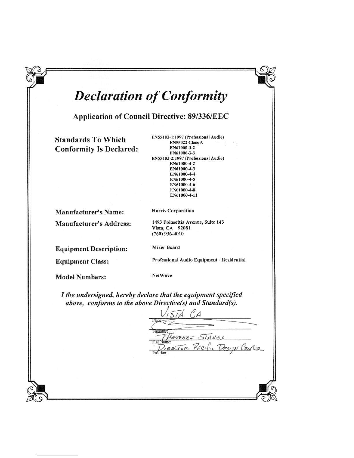
Declaration of Conformity
HARRIS CORPORATION
iv
Revision A • 6/06
Page 5
Safety Instructions
RR
ead Aead A
ll Instrll Instr
ucuc
tionstions
1.
R
ead A
ll Instr
RR
ead Aead A
ll Instrll Instr
instructions before operating the product.
RR
etain Aetain A
ll Instrll Instr
2.
R
etain A
ll Instr
RR
etain Aetain A
ll Instrll Instr
instructions for future reference.
HH
eed Aeed A
ll ll
3.
4.
5.
6.
7.
8.
9.
WW
H
eed A
ll
W
HH
eed Aeed A
ll ll
WW
on the product and those listed in the operating
instructions.
olloollo
w Aw A
FF
F
ollo
w A
olloollo
w Aw A
FF
product usage instructions.
HH
eaea
tt
..
H
ea
t
. This product must be situated away from any
HH
eaea
tt
..
heat sources such as radiators, heat registers, stoves,
or other products (including power amplifiers) that
produce heat.
VV
enen
tilatila
tion.tion.
V
en
tila
ti on . Slots and openings in the product are
VV
enen
tilatila
tion.tion.
provided for ventilation. They ensure reliable operation
of the product and keep it from overheating. Do not
block or cover these openings during operation. Do
not place this product into a rack unless proper
ventilation is provided and the manufacturer’s
recommended installation procedures are followed.
WW
aa
tt
er and Mer and M
W
a
t
er and M
WW
aa
tt
er and Mer and M
water such as a bathtub, wash bowl, kitchen sink, or
laundry tub, in a wet basement, or near a swimming
pool or the like.
AA
ttachmenttachmen
A
ttachmen
AA
ttachmenttachmen
recommended by the product manufacturer as they
may cause hazards.
PP
oo
ww
er Ser S
ourour
P
o
w
er S
our
PP
oo
ww
er Ser S
ourour
the type of power source indicated on the marking
..
uc
tions
. Read all safety and operating
ucuc
tionstions
..
ucuc
tionstions
..
uc
tions
. Retain all safety and operating
ucuc
tionstions
..
arar
ningsnings
..
ar
nings
. You must adhere to all warnings
arar
ningsnings
..
ll Instrll Instr
ucuc
tionstions
ll Instr
ll Instrll Instr
cc
c
cc
..
uc
tions
. Follow all operating and
ucuc
tionstions
..
oistur
ee
..
oistur
oistur
e
. Do not use this product near
ee
..
oisturoistur
tsts
..
ts
. Do not use any attachments not
tsts
..
eses
..
es
. You must operate this product using
eses
..
label and in the installation instructions. If you are not
sure of the type of power supplied to your facility,
consult your local power company.
GG
rr
ounding and Pounding and P
10.
G
r
ounding and P
GG
rr
ounding and Pounding and P
equipped with a polarized AC plug with integral safety
ground pin. Do not defeat the safety ground in any
manner.
PP
oo
ww
er Cer C
oror
d Pd P
rr
11.
P
o
PP
oo
routed so that they are not likely to be walked on nor
pinched by items placed upon or against them. Pay
particular attention to the cords at AC wall plugs and
convenience receptacles, and at the point where the
cord plugs into the product.
LighLigh
12.
Ligh
LighLigh
unplug it from the AC wall outlet during a lightning
storm or when it is left unattended and unused for
long periods of time. This will prevent damage to the
product due to lightning and power line surges.
OO
vv
13.
O
v
OO
vv
extension cords, or integral convenience outlets as this
can result in a fire or electric shock hazard.
OO
bjecbjec
14.
O
bjec
OO
bjecbjec
kind into this product through openings as they may
touch dangerous voltage points or short out parts,
which could result in a fire or electric shock. Never spill
liquid of any kind on the product.
AA
cccc
15.
A
cc
AA
cccc
cart, stand, tripod, bracket, or table. The product may
fall, causing serious injury to a child or adult and serious
damage to the product. Any mounting of the pr oduct
must follow manufacturer’s installation instructions.
otot
w
er C
or
d P
r
ot
ww
er Cer C
oror
d Pd P
rr
otot
tningtning
..
tning
. For added protection for this product,
tningtning
..
..
erer
loadingloading
loading
. Do not overload AC wall outlets,
er
..
erer
loadingloading
t and Liquid Et and Liquid E
t and Liquid E
t and Liquid Et and Liquid E
essoressor
iesies
..
essor
ies
. Do not place this product on an unstable
essoressor
iesies
..
tion.tion.
olarolar
izaiza
tio n. This product is
olar
iza
tion.tion.
olarolar
izaiza
ecec
tion.tion.
ec
tion. Power supply cords must b e
ecec
tion.tion.
nn
trtr
yy
..
n
tr
y
. Never push objects of any
nn
trtr
yy
..
PP
rr
oo
ducduc
t and Ct and C
arar
t Ct C
ombinaombina
16.
P
r
o
duc
t and C
PP
rr
oo
with care. Quick stops, excessive force, and uneven
surfaces may cause the product and the cart
combination to overturn.
SS
erer
17.
S
er
SS
erer
personnel.
DD
amage Ramage R
18.
D
amage R
DD
amage Ramage R
from the wall AC outlet and refer servicing to qualified
service personnel under the following conditions:
a. When the AC cord or plug is damaged.
b. If liquid has been spilled or objects have fallen into
the product.
c. If the product has been exposed to rain or water.
d. If the product does not operate normally (following
operating instructions).
e. If the product has been dropped or damaged in any
way.
f. When the product exhibits a distinct change in
performance. This indicates a need for service.
RR
eplaceplac
19.
R
eplac
RR
eplaceplac
required, be sure the service technician has used
replacement parts specified by the manufacturer or
that have the same characteristics as the original parts.
Unauthorized substitutions may result in fire, electric
shock, or other hazards.
SS
afaf
20.
S
af
SS
afaf
product, ask the service technician to perform safety
checks to determine that the product is in proper
operating condition.
CC
leaningleaning
21.
C
leaning
CC
leaningleaning
only a damp cloth for cleaning.
ar
ducduc
t and Ct and C
arar
vicingvicing
..
vicing
. Refer all servicing to qualified ser vicing
vicingvicing
..
equirequir
equir
equirequir
emenemen
t Pt P
emen
t P
emenemen
t Pt P
etet
y Cy C
heck.heck.
et
y C
heck. Upon completion of any repairs to this
etet
y Cy C
heck.heck.
..
. Do not use liquid or aerosol cleaners. Use
..
tion.tion.
t C
ombina
tion. Move this product
t Ct C
ombinaombina
tion.tion.
ing Sing S
erer
vicvic
ee
..
ing S
er
vic
e
. Unplug this product
ing Sing S
erer
vicvic
ee
..
arar
tsts
..
ar
ts
. When replacemen t parts are
arar
tsts
..
Hazard/Warning Label Identification
EE
xx
clamaclama
tion Ption P
oinoin
t symbt symb
The
E
x
clama
tion P
tion Ption P
oin
oinoin
CAUTION
RISK OF ELECTRIC SHOCK
DO NOT OPEN
EE
xx
clamaclama
within an equilateral triangle, alerts the
user to the presence of important
operating and maintenance (servicing)
instructions in product literature and
instruction manuals.
WARNING: SHOCK HAZARD - DO NOT OPEN
AVIS: RISQUE DE CHOC ELECTRIQUE - NE PAS OUVRIR
LighLigh
tning Ftning F
tning F
tning Ftning F
lash lash
lash
lash lash
olol
o l, within an
olol
The
Ligh
CAUTION: TO REDUCE THE RISK OF ELECTRIC SHOCK DO NOT
REMOVE ANY COVER OR PANEL. NO USER SERVICEABLE PARTS
INSIDE. REFER SERVICING TO QUALIFIED SERVICE PERSONNEL.
LighLigh
AA
rr
rr
oo
whead symbwhead symb
A
r
r
o
whead symb
AA
rr
rr
oo
whead symbwhead symb
equilateral triangle, alerts the user to
the presence of uninsulated
dangerous voltage within the
WARNING: TO REDUCE THE RISK OF FIRE OR ELECTRIC
SHOCK, DO NOT EXPOSE THE POWER SUPPLY OR CONSOLE
TO RAIN OR MOISTURE.
WW
ARNINGARNING
W
ARNING—This e qu ip me nt generates, use s, and can radiate radio frequency ener gy. If no t installed and used in accordance with the instructions in this
WW
ARNINGARNING
manual it may cause interference to radio communications. It has been tested and found to comply with the limits for a Class A computing device
(pursuant to Subpart J of Part 15 FCC Rules), which ar e designed to pro vide reasonable prot ection against such interference when operated in a commercial environment. Operation of this equipment in a residential area is likely to cause interference, in which case the user, at his own expense, will be
required to take whatever measures may be required to correct the interference.
product’s enclosure that may be of
sufficient magnitude to constitute a
risk of electric shock.
t symb
t symbt symb
WW
ithith
W
ith
WW
ithith
olol
ol,
olol
v
HARRIS CORPORATION
Revision A • 6/06
Page 6

HARRIS CORPORATION
vi
Revision A • 6/06
Page 7
Introducing
NetWav e
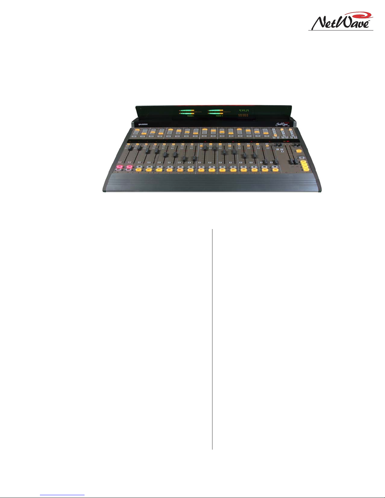
NetWave-16 Console
Thanks for joining the growing ranks of
broadcasters employing Harris Corporation prod-
ucts designed by PR&E. Our mission: provide the
finest quality products, systems , documentation and
after-sale support.
To obtain the maximum benefit from the
NetWave’s capabilities, read through the chapters
on
Installation
product installation.
and
Operation
prior to the actual
1
NetWave consoles hav e these parts:
• Main Frame: with 8, 16 or 24 channel slots
• Monitor & Output Card: one per console
• DSP & I/O Card: one on 8-input frames; two
on 16-input frames; three on 24-input frames
• Monitor Panel: one per console
• Dual Fader Panel: four on 8-input frames; six
on 16-input frames; nine on 24-input frames
• Reflective Display: clock, timer and two meters
are standard, an additional two meters can be
added to the NetWave-16 and NetW a ve-24
• Dual Width Blank Panel: two standard on
NetW ave-16; three on NetWave-24 (cover the
unpopulated channel slots)
• 48-volt Supply: an in-line supply is standard
on the NetWave-8 and NetWave-16; a rackmount supply is standard on the NetW a ve-24
(optional on the other frame sizes)
• Installation Materials: installation kit; NetWave CD-ROM; NetWave Quick Guide
• Toolkit (optional): 76-1901 toolkit
• Printed Manual (optional): 75-54 NetWave
Installation & Operation manual
1-1
HARRIS CORPORATION
Revision A • 6/06
Page 8

1 Introducing NetWave
Product Overview
NetWave is a low-profile, digitally-controlled,
VistaMax-compatible audio console that sits on
the countertop. Three frame sizes are available,
with 8, 16 or 24 channel slots .
Each NetWave operates as a stand-alone console but, for maximum flexibility and usability,
can be tied into any VistaMax system (running
500-series code) by installing the optional Link
Activation Kit (99-1425). The kit activates the
built-in VistaMax Link which, via a single CAT-5e
cable, ties the console to a VistaMax or Envo y Hub
card to allow any system source (audio signals or
audio signals with logic) to be routed to any NetW a ve channel and to the External Monitor inputs.
The VistaMax Link also sends a number of NetWave signals to the VistaMax system including:
one input from each channel (either the local analog or digital input can be chosen); each program
bus output; both mix-minus outputs (which ha ve
both a clean feed and an IFB feed); the two channel Telco record output; and the stereo cue bus.
These signals can then be routed to an y VistaMax
system destination as required.
To further enhance a “Linked” console, an optional Dual F ader panel upgrade, the Dual Router
Kit (99-1424), is also available. This kit adds in
VistaMax source selection ability to both channels on any Dual Fader panel.
The Reflective Displa y , with two stereo bargraph
meters (PGM 1 and auxiliary), a clock which can
be slaved to an ESE or a SMPTE master clock
and an Event Timer, is integrated into the frame
behind the control panels. Quad meter displa y kits
are available for the NetWave-16 (99-1990-16Q)
and for the NetWave-24 (99-1990-24Q) to add
dedicated Program 2 and Program 3 meters.
Two 48-volt power supplies are used with NetWave consoles: a rack mount supply (99-1205),
which is the same one used with VistaMax and
Envoy card frames and RMXd and BMXd consoles, comes standard with the NetWave-24; while
an in-line supply (50-27) comes standard with the
NetW av e-8 and 16 frame sizes. A 99-1205 supply
can also be used on the smaller NetWave frames.
An optional 90-1995 Power Coupler is available to allow any NetWave console to be redundantly powered by coupling in a second matching
48-volt supply.
The NetWave has an all-aluminum chassis,
which fully contains all circuit board electronics,
for strength and RFI immunity. To ensure silent
operation, all NetWave parts (console frame, control panels, console display and power supplies)
are convection cooled—meaning no fans, and completely silent operation.
All user audio and logic connections are made
from the top rear of the frame. Connector access is
via a removable flip-open cover which hides the
cabling and connectors during normal operation.
NETWAVE CONSOLE CONNECTIONS
•Monitor & Output Card:
» Four stereo Program bus outputs (each with
separate analog and AES digital outputs)
» Three stereo analog control room outputs (for
a room monitor amp and for separate host and
guest headphone amps)
» Three stereo analog studio outputs (for a stu-
dio monitor amp and for separate host and
guest headphone amps)
» Two stereo analog External Monitor inputs
» Two mono analog Mix-Minus outputs
Monitor and Output Card Connections
HARRIS CORPORATION
1-2
Revision A • 6/06
Page 9
DSP and I/O Card Connectors and Channel Setup Controls
1 Introducing NetWave
» Separate control room and studio logic con-
nectors (warning interface output, logic I/O
for dim and mute control, talk logic output)
•DSP & I/O Cards:
» Sixteen stereo/dual mono audio inputs (eight
analog and eight digital), assignable as the A
or B source for the eight channel control strips
associated with that card
» Eight channel logic connectors, assignable to
either the A or B source for the eight channel
control strips associated with that card
•Other Connections:
» One 1/4" TRS jack for the board operator
headphones, left side panel
» One RJ-45 VistaMax Link connector for a
CAT-5e cable (requires the optional Link Activation Kit be installed)
» One keyed connector for the 48-volt power
supply supplied with the console
» Four , eight or twelve internal RJ-45 sockets to
supply power and signals to the Dual Fader
panels
» Four, eight or twelve internal and rear panel
LAN passthru RJ-45 sockets for standard
CAT-5 cabling to connect the optional Dual
Router Kits to the VistaMax LAN
» One ESE or SMPTE master clock input on
the clock-timer board
» One Timer Reset output, for a studio event
timer , on the clock-timer board
MAIN COMPONENT DESCRIPTIONS
NetWave board operators use three parts: the
Dual Fader panels; the Monitor panel; and the
Reflective Console Display . Each is cov ered in this
section along with descriptions for the other parts
making up the console: 48-volt power supplies,
the Monitor & Output card, the DSP & I/O card,
the VistaMax Link and the optional upgrade kits.
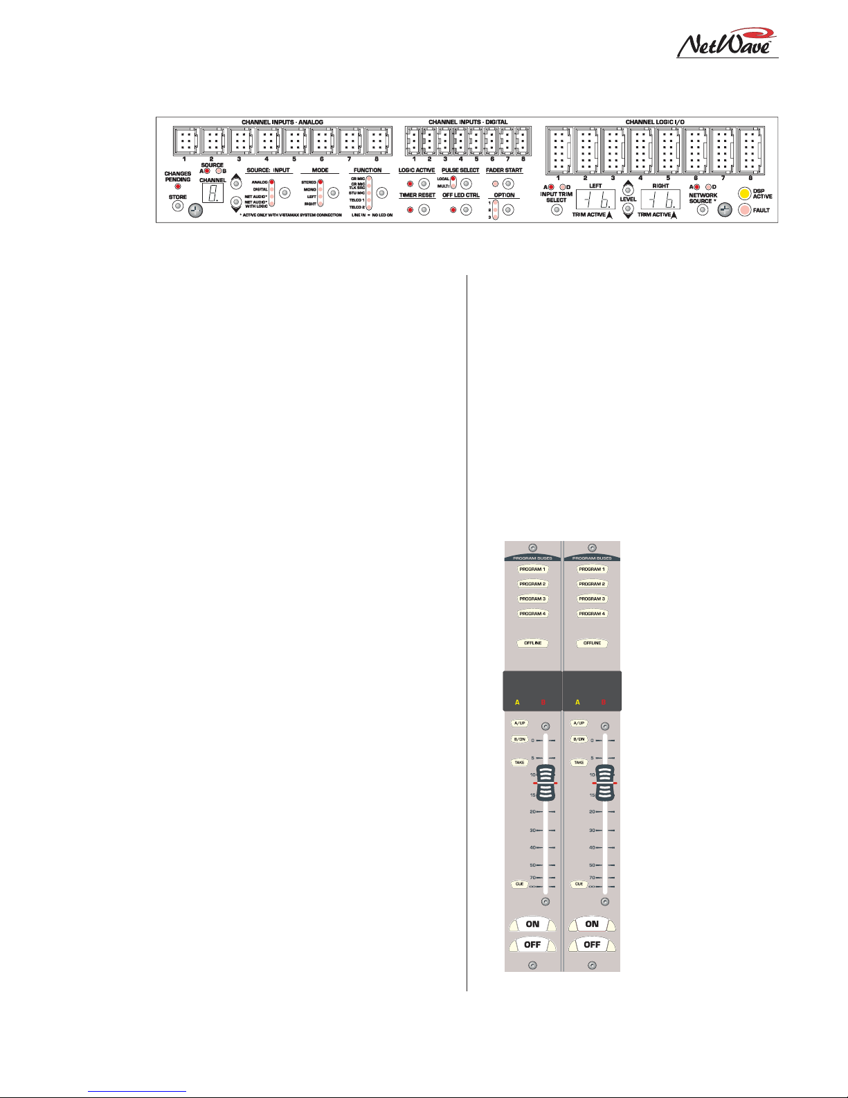
NetWa ve Dual Fader Panels
Each Dual Fader panel has two channel control
strips. Each strip has the following features: sepa-
rate channel on and off
buttons; a 100mm fader
for channel level control;
cue on/off button; A and
B source selector buttons
with a Take button; active
source illuminated label;
and five bus assignment
buttons (four Program
and one Offline).
Channel control is digital, so no audio ev er travels through the Dual
Fader panel. In fact, a
Dual Fader panel can be
swapped “hot” without affecting either channel’s
audio performance.
Each Dual F ader panel
plugs into a DSP & I/O
card using a single red
Dual Fader Panel
1-3
HARRIS CORPORATION
Revision A • 6/06
Page 10
1 Introducing NetWave
CAT-5 cable. Since each DSP & I/O card carries
eight audio channels, up to four Dual Fader panels are plugged into each DSP & I/O card.
Each Dual F ader channel control strip has two
audio inputs and one logic I/O connector associated with it on the DSP & I/O card. Since each
channel strip has two possible sources (A and B),
which audio input is used for each source is assigned during console setup . In the standard, nonlinked, NetWave console the two possible inputs
are the local analog input or the local digital input assigned to that channel on the DSP & I/O
card. When the NetWave is linked to a VistaMax
system, there are three selections per source: the
local analog input, the local digital input, or a
routed VistaMax source.
The operating parameters for each source, on
each channel, are independently set during console setup through a common group of setup buttons and LEDs on each DSP & I/O card (shown
in the illustration on the previous page). These
controls set the parameters used when the A and
the B source is selected. The parameters include:
input type (is the input a control room mic, a studio mic, a line input or a Telco input?); whether
logic is be associated with that input; whether the
event timer is reset at channel on; whether fader
start is active; etc. The parameter settings are
stored in nonvolatile RAM.
The channel strip’s A and B select buttons are
used along with the Take button to choose the
active source for that channel. W hen the A source
is active, yellow LEDs backlight the A source label under a smoked polycarbonate window above
the A button, and the A button is lit. When the B
source is active, red LEDs backlight the B source
label above the fader and the B button is lit.
Setting a channel source to use the logic I/O
means the channel can remotely control a peripheral device (mic control panel, CD player, computer playback system, etc.) and that peripheral
can also control the channel. The logic I/O provides fully independent parallel logic functions
that: outputs start and stop pulses to line devices
(on and off tallies to mic panels); receives channel
on, off, cue and reset/ready commands from line
devices (on, off, cough and talkback commands
from mic panels).
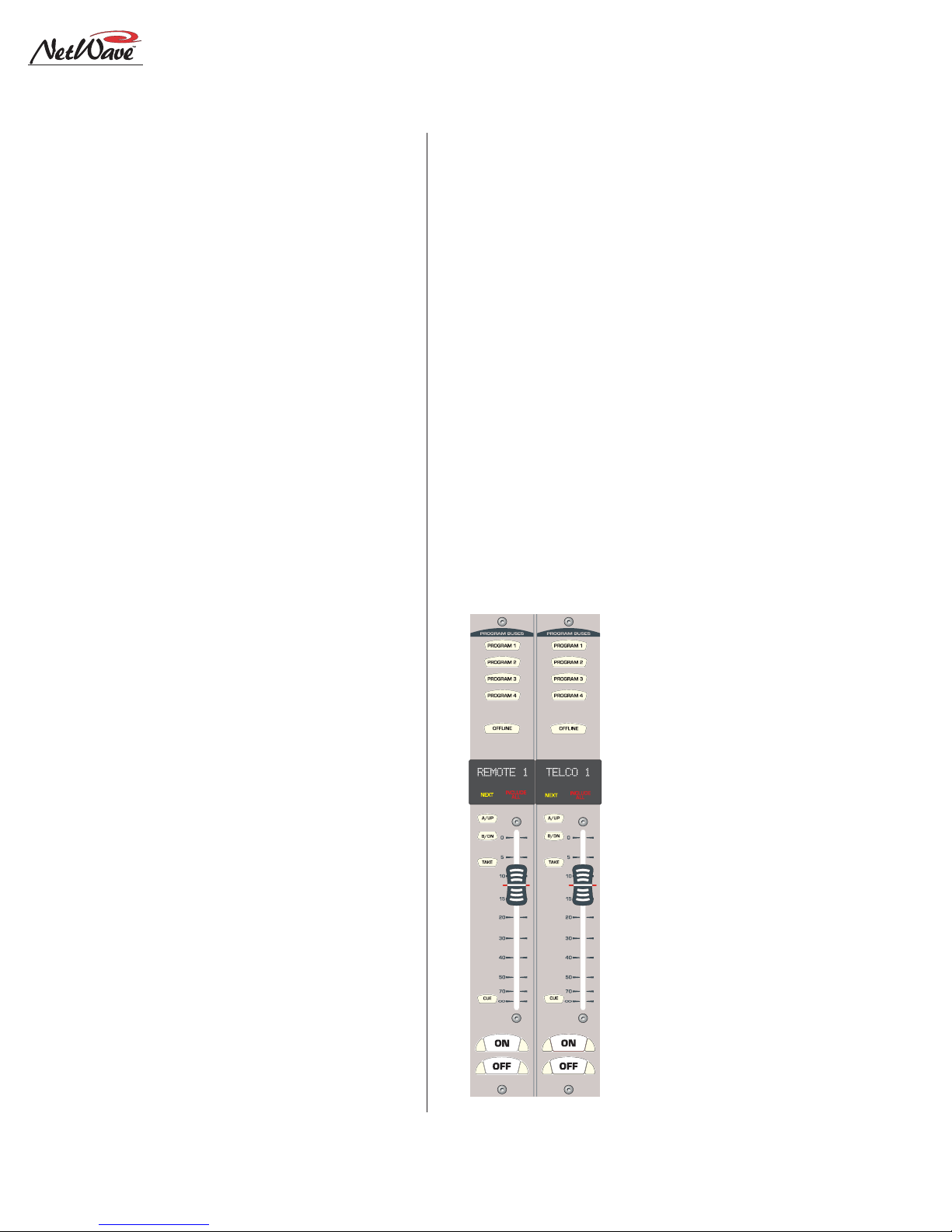
Dual Router Channels
The optional Dual Router Kit changes the A/B
selector buttons on both channels of any Dual
Fader panel into VistaMax source selector Up/
Down buttons. To use this functionality, the
console’s VistaMax Link must be active.
Dual Fader panels that have the Dual Router
Kit installed are easily identified by the two 10character signal name displays under the top half
of the smoked polycarbonate lens above the fader .
The display normally shows the name of the cur-
rent VistaMax source
feeding that channel.
But, when finding the
next source by pressing
an Up or Down button,
the displayed name
switches to show a potential Next Source for
that channel. The yellow
Next label above the Up
button lights while the
Next Source name is displayed. Holding down, or
repeatedly tapping the
Up or Down button,
steps alphanumerically
through the list of potential Next Source names
available on that channel.
Once the desired
Dual Router Panel
source name is shown,
HARRIS CORPORATION
1-4
Revision A • 6/06
Page 11
1 Introducing NetWave
pressing the Take button selects that source—when
the channel is off. New routed sources cannot be
taken when the channel is on (the On button
flashes three times to indicate the next source cannot be taken while the channel is on). But, a next
source can be pre-selected and then taken once
the channel is turned off.
Which sources are seen when the Up and Down
buttons are pressed on the router channel is set
using the VistaMax Control Center (VMCC) software, vers 1.1 or later. Each channel could be assigned anywhere from one source up to every av ailable source in the VistaMax system in its selection
list. In regular use, the signal list is kept short to
make it easy for board operators to easily find
desired sources. If a board operator needs to selected a source that is not shown, pressing both
the Up and Down buttons together turns on the
Include All function, lighting up the red Include
All label. Every source available to the console’s
parent device is now displayed. Pressing both Up
and Down buttons together again turns off the Include All function.
The VMCC 1.1 software is included on the NetWave CD-ROM (99-5001) that comes with the
console.
To integrate the NetWave with a VistaMax or
Envoy card frame, the VistaMax devices must be
running 500-series code. The current operating
system code build can be viewed by opening the
release.txt file on the parent card frame or
by using Community Monitor, another program
included on the NetWave CD-ROM.
Operating System Code build,
as shown in the release.txt file
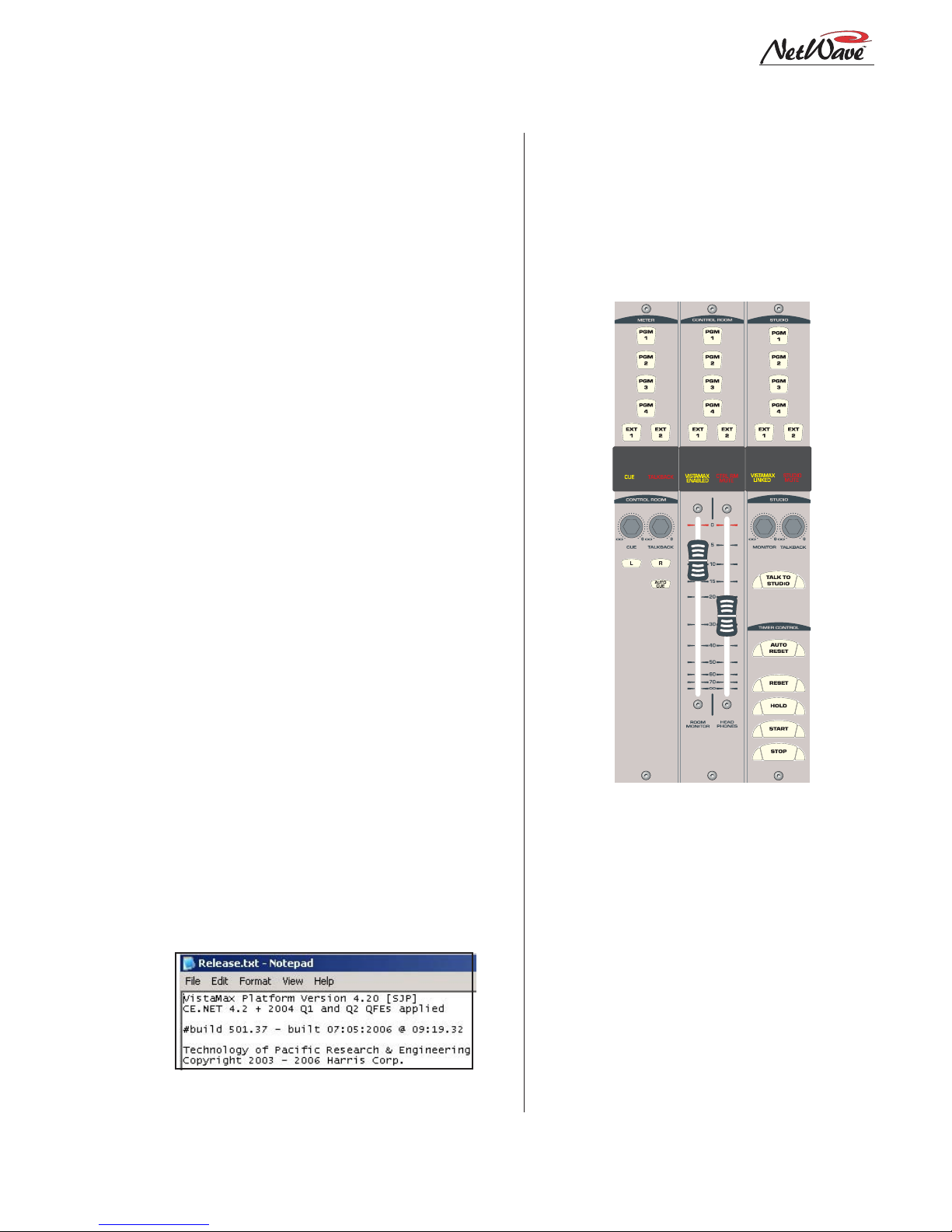
Monitor Panel
This standard panel is divided into three sections
separated by double graphic lines. From left to
right the sections, divided by main function, are:
Aux Meter control; Control Room control; and
Studio control.
Monitor Control Panel
Aux Meter Section
The top of all three sections have exclusiv e action
source selector buttons to select one monitor signal
from the PGM 1 thru 4 buses and the two External
Monitor inputs. In the Aux Meter section, the
buttons select which signal feeds the right-most
meter in the Reflective Display, with the selected
source name shown below the Aux Meter.
Note that the Aux Meter is normally set to
alternately display the cue levels while cue is active
(when the cue label is lit, Cue is displayed below
the meter and the cue level is shown).
1-5
HARRIS CORPORATION
Revision A • 6/06
Page 12

1 Introducing NetWave
Several Control Room controls are located below
the meter selector buttons in this section of the
panel. They are covered in the Control Room
Section that follows.
Control Room Section
The middle of the panel has the control room
monitor source selector buttons and the two faders
to control the room monitor speaker level and the
operator headphone output level.
Any one source can be selected to feed all control
room monitor outputs. The active source button
lights to indicate its selection.
A cue speaker, at the left end of the console
display, is level controlled by the cue pot in the
middle of the left-hand section. A cue indicator
(yellow) lights while cue is active.
A talkback pot controls the level of incoming
talkback that feeds the cue speaker independently
of the cue volume pot. A Talk to Control Room
indicator (red) lights while a studio microphone
is talking to the control room.
A control room monitor output fader and the
operator headphone output fader are at the bottom of the center section.
The signal mode for both the control room and
studio outputs is set by the Monitor Mode buttons in the left-hand section (below the cue and
talkback pots). The L and R buttons control
whether the monitor signal for all outputs is stereo (when neither button is lit), left only (when L
is lit), right only (when R is lit) or a mono sum
signal (when L and R are both lit) where the left
and right signals are summed together to feed all
monitor outputs.
Just below the R mode button is the AutoCue
button. When lit, the operator’s headphone output automatically switches to feed the cue bus into
the operator’s headphones while cue is active.
When unlit, cue activity does not affect the board
operator’s headphone audio. AutoCue has two
modes of operation (set by switch DS1-3 on the
Monitor & Output card). The default setting is Split
Cue, where the monitor and cue audio are separately summed to mono before feeding the operator headphones. Cue audio is sent to the one ear
while the monitor audio goes to the other ear . T his
is typically used when the console is in an on-air
studio.
The second AutoCue mode is Stereo Cue, where
stereo cue audio replaces the monitor audio source
in the headphones. This setting may be desirable
for production rooms and other off-air applications.
Studio Section
The right-hand section of the Monitor panel has
the monitor source selection buttons and level
controls for a separate talk or voice studio. One
source can be selected from among the six buttons
at the top of the center section. The selected source
button lights to indicate its selection.
The two pots in this section control the output
level of a dedicated studio monitor output
(Monitor) and the amount of talk to studio audio
(Talkback) that is fed to the monitor output.
This section of the Monitor Control panel also
has a Talk to Studio button to allow the board
operator to talk to the studio using the board
operator mic. If desired, multiple control room
mics can be assigned as talk sources to enable both
a board op and a producer to talk to the studio
without having to add a mic control panel.
Five event timer control buttons are at the
bottom of this section. Start, Stop, Hold and Reset
manually control the event timer in the Console
Display. When the Auto Reset button is lit, the
timer can be reset automatically when a channel
is turned on. Which channel sources reset the timer
are set during installation using the DSP & I/O
card setup controls.
HARRIS CORPORATION
1-6
Revision A • 6/06
Page 13

1 Introducing NetWave
Reflective Console Display
The integrated Reflective Console Display is located just behind the Dual Fader and Monitor
panels. The standard display has two stereo bargraph meters with the left one showing the PGM
1 output levels. The right-hand, or Aux Meter,
shows a source selected using the Meter source
controls on the Monitor panel. Two more stereo
bargraph meters (for Program 2 and Program 3)
can be added to the larger frame sizes by installing the optional Quad Meter kit.
A time of day clock and an event timer are also
in the Console Display . The default operating mode
for the clock is autonomous, meaning the clock
runs independently and must be set by hand. The
clock time remains current for about three days
with the power off. After that, the time must again
be set. The clock can alternately be slaved to a
SMPTE, ESE TC-89 or ESE TC-90 master clock.
In this mode, the time set buttons are not active.
The event timer is controlled by Monitor panel
buttons, as well as reset commands from one or
more channels when the Auto button is lit.
Monitor & Output Card
Each NetW a ve console has one Monitor & Output card with the user connections listed on page
1-2. The Monitor panel plugs into the Monitor &
Output card, receiving power and control signals.
The card also supplies power and clock signals,
and sends and receives bused audio signals, to the
DSP & I/O cards via a short flat cable jumper.
There are two LEDs, to indicate operational status (DSP clock and F ail), and a console reset button located on the Monitor & Output card.
The Monitor & Output card is located below
and behind the Monitor panel and Reflective Console Display. In normal operation the card connections are hidden by a cosmetic flip-open rear
cover.
DSP & I/O Cards
Each DSP & I/O card (Digital Signal Processor
plus Inputs and Outputs) has the setup controls,
audio inputs and logic I/O connectors for eight
console channels. The channels are on the four
Dual F ader panels that mount directly in front of
each card. A DSP Active and a Fault LED indicate operational status on each card.
There is one DSP & I/O card on NetWave-8
consoles, two on NetWave-16 consoles and three
on NetWave-24 consoles. In normal operation, the
DSP & I/O cards are completely hidden from the
operator by a cosmetic flip-up cover.
Each DSP & I/O card has twelve RJ-45 connectors. Eight are internal connectors for four Dual
F ader panels (using red CA T-5 cables supplied with
the frame); the other four RJ-45 connectors are
for optional Dual Router Kits (which plug in using a supplied blue CAT-5 cable). Customer-supplied CAT-5 cables then connect the Dual Router
kits to the VistaMax LAN using the four rear panel
RJ-45 passthru connectors.
Each DSP & I/O card has a common set of assignment buttons and indicator LEDs to assign
the parameter settings for each A and B source on
the eight channels associated with that DSP &
I/O card. The setup parameters include: input selection (analog, digital or network); mode selection (stereo, L, R or mono); signal function (mic,
line, Telco); whether the logic I/O is active; input
left and right gain trims for both analog and digital inputs; network source assignment; and other
logic settings.
Pow er Supply
Two different power supplies are used with NetWave consoles. Each has a single 48-volt output
on a keyed DC connector and each is supplied
with a detachable IEC AC cord.
An in-line supply (50-27) is standard on the NetWave-8 and -16 consoles. It has a captive six foot
1-7
HARRIS CORPORATION
Revision A • 6/06
Page 14

1 Introducing NetWave
DC cable which allows the supply to sit below the
console within the cabinetry. This supply is not
recommended for use with a NetWave-24 console.
NetW av e-24 consoles ship with a Universal 48volt Supply (99-1205), which is also used by
VistaMax card frames and RMX
soles. A fifteen foot detachable DC cable (90-1858-
1) connects that supply to the console.
One supply, either the 50-27 or the 99-1205,
comes standard with each console. A second
matching redundant supply can be connected to
any NetWave console by using the optional 901995 Power Coupler.
NOTE: When adding a 99-1205 supply for redundant powering, order a 99-1205-1 supply (it includes a 90-1858-1 fifteen-foot DC cable).
The 99-1205 supply has a recessed front panel
on/off switch and a green LED to indicate the 48volt output is good. The 50-27 supply has a green
LED on the top of its case to indicate its 48-volt
output is good but it does not have a power switch.
Each supply is designed for continuous 24/7
operation and is fully regulated and protected
against excessive current by internal fuses and electronic safeguards.
d
and BMXd con-
VistaMax Link
The RJ-45 VistaMax Link connector is located
next to the DC input connector on the rear panel.
This connector links the NetWave console to a VistaMax or Envoy Hub card in order to network
the console with a VistaMax system. The optional
Link Activation Kit must be installed to use the
Link connection.
Once activated, the Link sends up to 32 stereo
signals (the four program buses, cue bus, Telco
record output, two dual channel mix-minus signals and one input from each channel) to a
VistaMax network as source signals. Up to 26 ste-
reo destinations (two routed External Monitor inputs and one input for each channel) are routed
from the VistaMax system to the console.
Specifications
Listed for the basic signal paths, per channel,
with 100k ohm loads connected to the analog program outputs in a full NetWave-24 frame.
0 dBu=0.775 volts RMS, regardless of circuit
impedance (equal to 0 dBm into 600 ohms). Noise
measurements done using a 20 kHz bandwidth
(add 1.7 dB for a 30 kHz bandwidth).
Total Harmonic Distortion (THD+N) is measured using a +18 dBu output with a swept signal
and a 20 kHz low pass filter.
FSD (Full Scale Digital) = +24 dBu
Analog Line Inputs
Input Impedance: >60 k ohms, balanced
Nominal Input Level: +4 dBu (each input can be
independently trimmed by +/-15dB)
Input Headroom: 20 dB above nominal input
Analog Outputs
Output Source Impedance: <3 ohms, active balanced
Output Load Impedance: 1k ohms min.
Nominal Output Level: +4 dBu
Maximum Output Level: +24 dBu
Digital Inputs and Outputs
Reference Level: 20 dB below FSD
Input Level: each input can be independently
trimmed by +/-15 dB
Signal Format: AES-3, S/PDIF (input only)
AES-3 Input & Output Compliance:
conversion
Digital Reference:
slave (external) at 48 kHz ±100 ppm
Internal Sample Rate:
Output Sample Rate: 48 kHz nominal (each can be
set for 44.1 kHz)
Crystal (internal) or VistaMax
48 kHz
24-bit sample rate
HARRIS CORPORATION
1-8
Revision A • 6/06
Page 15

1 Introducing NetWave
Digital Inputs and Outputs (cont.)
Processing Resolution: 24-bit fixed with extended
precision accumulators
Conversions:
sampling on all digital inputs; D/A: 24-bit,
Delta-Sigma, 128x ov ersampling
Latency:
A/D: 24-bit, Delta-Sigma, 128x over -
<600µs, an y input to monitor output
Monitor Outputs
Output Source Impedance: <3 ohms, activ e balanced
Output Load Impedance: 1 k ohms min.
Output Level: +4 dBu nominal, +24 dBu max.
Frequency Response
Input to Program Output: +0.3 dB/-0.1 dB, from
20 Hz to 20 kHz
Dynamic Range
Analog Input to Analog Output: 106 dB referenced to
FSD, 108 dB “A” weighted to FSD
Analog Input to Digital Output: 108 dB referenced to
FSD, 110 dB “A” weighted to FSD
Digital Input to Analog Output: 108 dB referenced to
FSD, 111 dB “A” weighted to FSD
Digital Input to Digital Output: 115 dB
Total Harmonic Distortion + Noise
Analog Input to Analog Output: <0.003%, 20 Hz to
20 kHz (<0.002% typical at 1k), +18 dBu input, +18 dBu output
Analog Input to Digital Output:
20 kHz,+18 dBu input, -6 dB FSD output
Digital Input to Analog Output:
20 kHz (<0.002%, typical at 1 kHz), -6 dB FSD
input, +18 dBu output
Digital Input to Digital Output:
20 kHz, -6 dB FSD input, -6 dB FSD output
<0.0009%, 20 Hz to
<0.003%, 20 Hz to
<0.0005%, 20 Hz to
Crosstalk Isolation
Program-to-Program: -85 dB, 20 Hz to 20 kHz
Console Power Requirements
Measured at 120 V AC/60 Hz.
NetWave-8: 54 watts
NetWave-16: 99 watts
NetWave-24
:
141 watts
Required Supply Voltage
NetWave-8: +48 VDC @ 1.2 amps
NetWave-16: +48 VDC @ 2 amps
NetWave-24
One power supply included. The NetW a ve-8 and
NetW av e-16 use a 50-27 supply . The NetWave24 uses a 99-1205 supply.
An optional Power Coupler (90-1995) is avail-
able for adding a matching redundant supply
for on-air consoles.
:
+48 VDC @ 3 amps
Power Supply Ground
Rack mount or in-line power supply: grounded through
the AC input cord ground pin
Power Supplies
AC input voltage & frequency: 90-240 V AC, 50/60 Hz
AC input: detachable IEC power cord
DC output: Uses a keyed, latching connector on a
captive cable on the 50-27 supply or a detachable cable (90-1858-1) on the 99-1205 supply
Dimensions
All NetWave consoles: 3" [76] max height abov e coun-
tertop, except for console reflector, 6" [152].
Front-to-back depth is 21" [533].
NetWave-8 is 20" [508] wide
NetWave-16 is 32.4" [823] wide
NetWave-24 is 45.2" [1148] wide
50-27 (in-line supply for NetWave-8 and NetWave-16):
2" [51] x 3.8" [97] x 9.5" [241]
99-1205 (rack mount supply for NetWave-24):
2 RU: 3.5" [89] x 19" [483] x 10" [254]
All dimensions: Height x Width x Depth.
Stereo Separation
Analog Program Outputs: >90 dB, 20 Hz to 20 kHz
Harris Corporation reserves the right to change
specifications without notice or obligation
1-9
HARRIS CORPORATION
Revision A • 6/06
Page 16

1 Introducing NetWave
Warranty
NetWave consoles carry a manufacturer’s warranty which is subject to the following guidelines
and limitations:
A) Except as expressly excluded herein, Harris
Corporation (“Seller”) warrants equipment of
its own manufacture against faulty workmanship or the use of defective materials for a period of one (1) year from the date of shipment
to Buyer. The liability of the Seller under this
Warranty is limited to replacing, repairing or
issuing credit (at the Seller’s discretion) for an y
equipment, provided that Seller is promptly
notified in writing within five (5) days upon
discovery of such defects b y Buyer , and Seller’ s
examination of such equipment shall disclose
to its satisfaction that such defects existed at
the time shipment was originally made by
Seller, and Buyer returns the defective equipment to Seller’s place of business per the
Seller’s RA procedures and directions, packaging and transportation prepaid, with return
packaging and transport guaranteed.
E) This Warranty is void for equipment which has
been subject to abuse, improper installation,
improper operation, improper or omitted
maintenance, alteration, accident, negligence
(in use, storage, transportation or handling),
operation not in accordance with Seller’s operation and service instructions, or operation
outside of the environmental conditions specified by Seller.
F) This Warranty is the only warranty made by
Seller, and is in lieu of all other warranties,
including merchantability and fitness for a particular purpose, whether expressed or implied,
except as to title and to the expressed specifications contained in this manual. Seller ’s sole
liability for any equipment failure or any
breach of this Warranty is as set forth in subparagraph A) above; Seller shall not be liable
or responsible for any business loss or interruption, or other consequential damages of an y
nature whatsoever, resulting from any equipment failure or breach of this warranty.
B) Equipment furnished by the Seller, but manu-
factured by another, shall be warranted only
to the extent provided by the other manufacturer.
C) Thermal filament devices, such as fuses or
lamps, are expressly excluded from this warranty.
D) The warranty period on equipment or parts
repaired or replaced under warranty shall expire upon the expiration date of the original
warranty.
HARRIS CORPORATION
1-10
Revision A • 6/06
Page 17
Installation
3
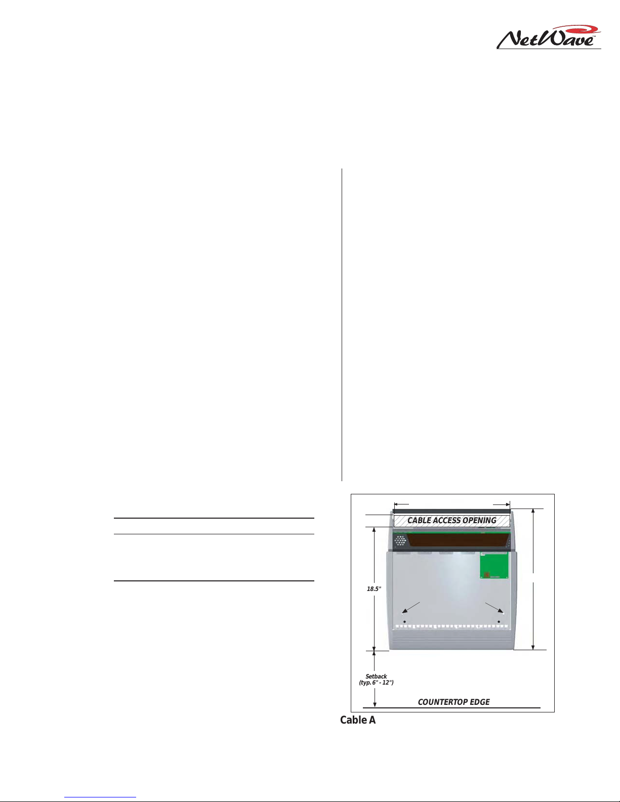
The NetW ave console sits on the countertop
on four rubber feet. One cable access cutout is re-
quired under the frame for cabinet wiring to cleanly
connect to the console connectors. These are hid-
den under a cosmetic cover after installation. For
security and stability , the console should be fastened
2
The NetWave console shipment contains:
• NetWave main frame, loaded with DSP & I/O
and Monitor & Output cards; a Monitor panel;
Dual Fader panels (NetWave-8 has four; NetW ave-16 has six plus two dual blanks; NetW av e24 has nine plus three dual blanks); optional
items ordered (additional Dual Fader panels, VistaMax Link Activation Kit, Dual Router Kits,
Quad Meter Package)
• 48-volt DC power supply (50-27 in-line supply
or a 99-1205 rackmount supply and DC cable)
to the countertop using two #8 or #10 screws or
bolts (not supplied). Two .256" chassis holes be-
hind the front two feet are provided for this. F rame
sizes and cutout dimensions are listed below .
Dimension Table
Frame Size Width Cable Access Dims.
NetWave-8 20" [508] 2" x 17" [51 x 432]
"
NetWave-16 32.8" [833] 2
NetWave-24 45.6" [1158] 2" x 43" [51 x 1092]
NetWave consoles are 21" [534] deep (from the front of the palm rest
to the back tips of the side panels). Add .5" [13] additional clearance behind the console in order to fully open the connector cover
when the console’s rear is against a wall.
The console height above the countertop is 3" [76], except for the console display reflector, which is 8" [203] above the countertop.
Typical console setback from the countertop edge to the palm rest is between 6" [152] and 12" [305].
Millimeter dimensions listed in brackets. All dimensional tolerances are:
±¼" [6.4].
x 30" [51 x 762]
• Installation kit (MOD IV housings and receptacle contacts, blank source name labels)
• Channel Setup Stylus Tool
• Reflector for the Console Display
• NetWa ve Quick Guide
• NetWave CD-ROM
See Dimension Table for Width
234567890123456789012
2"
18.5"
Setback
(typ. 6" - 12")
CABLE ACCESS OPENING
.256" holes to fasten
console to countertop
NetWave-8 console with Dual Fader and
Monitor Control panels removed
COUNT ERTOP EDGE
21"
Cable Access Cutout & Console Mounting holes
2-1
HARRIS CORPORATION
Revision A • 6/06
Page 18
2 Installation
Console Installation
The 99-5001 NetWave CD-ROM has
several video files on console installation; on installing optional items; on
setting up the console channels; and
on typical console operations.
GENERAL WIRING INFO
To facilitate console installation, create a wire
list of all console interconnections to and from peripheral devices. Identify and create tags for each
audio and logic cable. List these connections in a
master facility wiring logbook to ease installation,
future system wiring or equipment changes and
system troubleshooting.
Pages 2-18 to 2-22 cov er wire preparation and
connector installation. Page 2-23 has block diagrams for the various NetWave logic connectors.
Pages 2-27 to 2-30 show typical peripheral connections for a mic, a CD player, a computer playback system and linking to a VistaMax system.
Audio cables to/from the console should always
be run with the maximum practical distance from
all AC power mains wiring within the cabinetry.
The console’ s 48-volt power cable carries only DC
voltage so audio wiring can run parallel or be tie
wrapped to this cable without problem.
The channel audio and logic wiring connects
sequentially along the back of the console in eight
channel groups. The chassis metal is cutaw ay between the DSP & I/O cards to facilitate getting
the connectors and wiring up through the countertop.
To ease installation, break out each group of
cables, using the dimensions shown below as measured from the right end of the cutout. Cabling is
normally broken out and tie wrapped to the bottom of the countertop just behind the cable cutout. Lea ve a six to eight inch service loop on each
cable to ease installation and future wiring
changes. This extra cabling hangs down into the
cabinet (or the cable tray) after being connected.
The monitor and program outputs connect at
the right corner of the console along with the 48volt supply, the optional Link cable and the technical ground wire. The chassis is also cutout in
this area to ease installation.
Plug in all audio and logic cables first. Then
route the excess cabling (i.e., service loops) into
the cabinet by folding the audio and logic wires
over their connectors and arranging the cables to
go into the gap between the connectors and the
flip-up connector cover such that the cover sits
down onto the chassis behind the console display .
The technical ground wire, DC cable and any
Link and LAN cables can now be connected.
POWER SUPPLY PLACEMENT
Two types of power supplies are used with NetWave consoles. Each has a single 48-volt DC output using a keyed and locking connector. Each
uses an IEC AC input cable which is shipped with
a USA-type plug. The AC connector, or the IEC
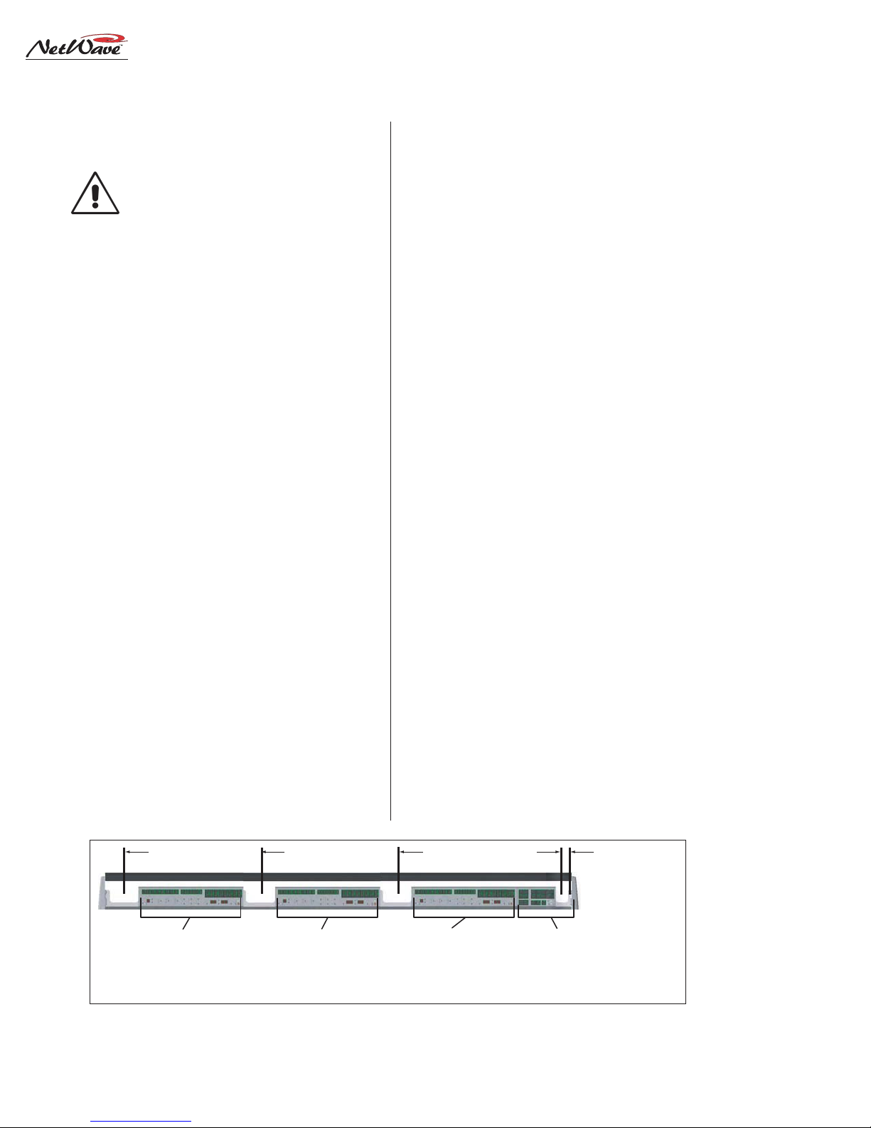
41" 28" 16" 1" 0"
AUDIO INPUTS & LOGIC I/O
CH 1-8 (NETWAVE-24)
AUDIO INPUTS & LOGIC I/O
CH 9-16 (NETWAVE-24)
CH 1-8 (NETWAVE-16)
Console Connections with Access Points (measured from the right end of the cable cutout)
HARRIS CORPORATION
AUDIO INPUTS & LOGIC I/O
CH 17-24 (NETWAVE-24)
CH 9-16 (NETWAVE-16)
CH 1-8 (NETWAVE-8)
2-2
Revision A • 6/06
CR AND STUDIO AUDIO & LOGIC OUTPUTS,
PGM BUSES & MIX-MINUS OUTPUTS,
EXT MON INPUTS,
TECHNICAL GROUND POINT,
48VDC SUPPLY INPUT,
LINK CONNECTOR
Page 19
2 Installation
cord, will have to be changed for overseas operation. Both supplies operate from 90 to 240 VAC
on 50 or 60 Hz power .
The 50-27 in-line supply comes standard on the
NetWave-8 and NetWave-16 consoles. It has a
captive six-foot DC cable, so it must be located
near the right rear corner of the console. It is typically set on the wire tray or within the cabinet (it
can be tie wrapped to a vertical wall to save space).
This supply will get warm under normal use as it
uses free air space for ventilation, so it must never
be covered or enclosed.
The 99-1205 Universal 48-volt Supply comes
standard on the NetWave-24. It requires 2 RU of
rack space within the console cabinetry, typically
located below and to the left or right of the console. It is the same supply used with VistaMax card
frames and consoles. A detachable 15-foot DC
cable (90-1858-1) connects this supply to the
NetWave console.
Either supply must be installed such that the
keyed 48-volt supply cable is not under any tension when routed through the cabinet. The 48volt cable locks into a keyed power connector on
the right rear corner of the NetWave chassis.
A 90-1995 Power Coupler (optional) is available to add a redundant power supply for on-air
consoles. T he main and redundant power supplies
plug into its special Y-cable, which then plugs into
the console. It hangs below the countertop.
AC GROUNDING NOTE: Do not
defeat the IEC power cord “U” safety
ground in any way, as this may create
a potentially dangerous condition to
the operator .
GROUNDING AND SHIELDING
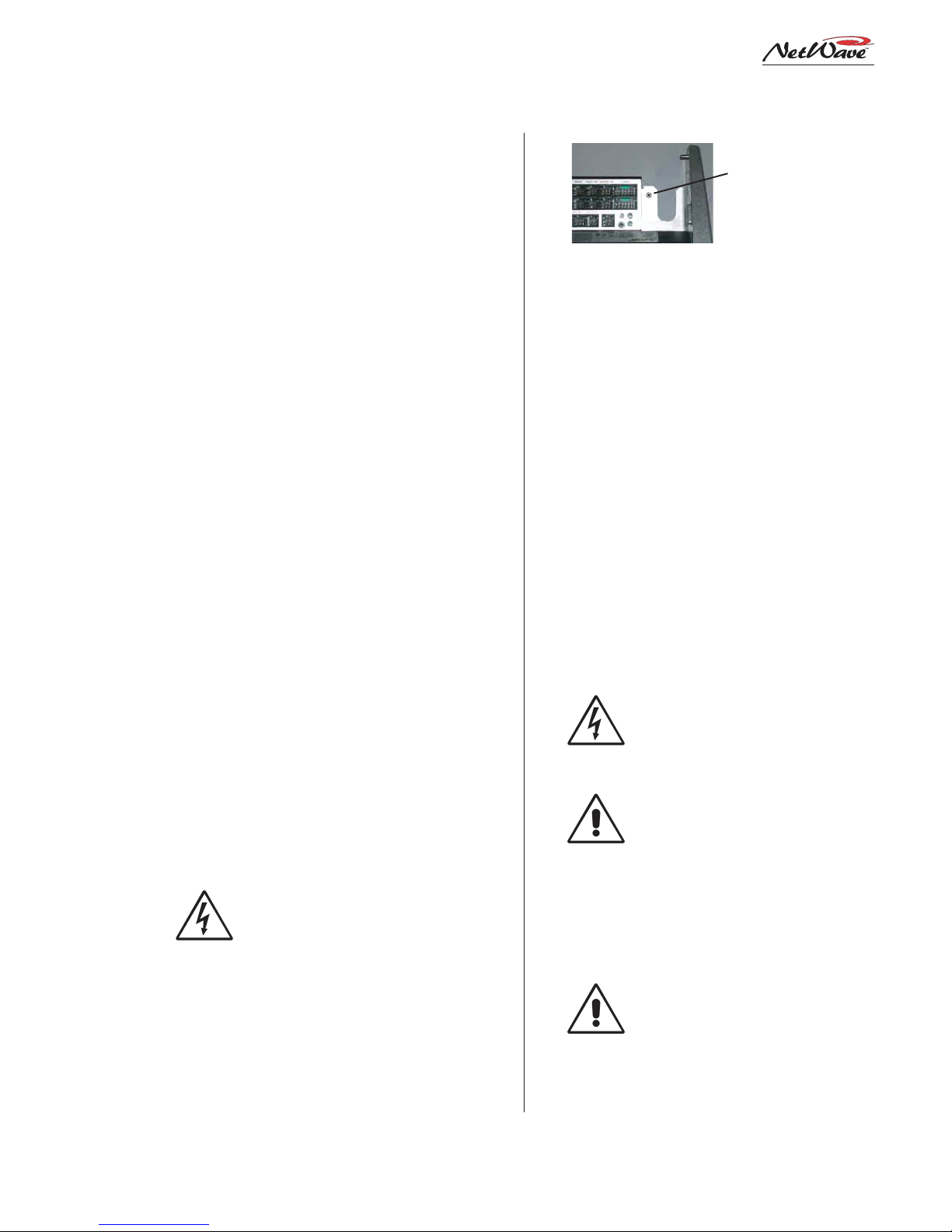
Terminate the facility’s technical ground wire
for the console into a crimped ring tongue terminal suitable for a #8 stud. Fasten the ground wire
Tie a 14-16 AWG
ground wire to this
screw using a ring
tongue fastener
Technical Ground Connection Point,
NetWave Chassis, r ight rear view
to the NetWave chassis using the #8 chassis screw
behind the Link connector.
When all system components share a common
ground potential (by using isolated ground AC outlets tied individually back to the main technical
ground), the audio cable shields can be connected
at both the console and the peripheral ends.
If isolated ground AC outlets are not used, connect the cable shields at the console end only. Do
not connect the shields on the peripheral device
end. Ensure the peripheral devices connect to a
clean ground through their power cords or through
separate ground wires to the facility’s technical
ground.
GROUNDING NOTE: The Power Sup-
ply chassis connects to the AC mains
safety or “U” ground wire.
AUDIO GROUND NOISES: Buzz
pickup is generally electrostatic—such
as capacitive coupling between an audio line and an A C power line. To avoid
audio ground noises, do not route audio wires in the same wireway as an
AC power line.
NOTE: Strong electromagnetic fields
from peripheral equipment using
switching power supplies may impair
NetWave performance, so keep these
products as far away as practical from
the console’s location.
2-3
HARRIS CORPORATION
Revision A • 6/06
Page 20
2 Installation
COUNTERTOP PREPARATION
Follow the dimensions listed on page 2-1 to
mark and router the cable access opening through
the countertop and substrate. Always radius the
corners to prevent laminate cracks.
NOTE: If the console will be set against a wall,
leave a .5" [13] gap between the side panels and
the wall in order to flip-up the connector cover.
Center the console over the cable access cutout
so that the rear connector cover , when closed, covers the cutout.
For security or stability the console can be fastened to the countertop. To do this, the leftmost
Dual Fader panel and the Monitor Panel must be
removed to access the two chassis holes (see page
2-1 for hole locations).
pilot holes for screws or clear holes for bolts. On
laminate countertops it is important that the hole
through the laminate is larger than the screw or
bolt threads to prevent future laminate cracks.
Use #8 or #10 screws or bolts to fasten the console to the countertop substrate. Do not deform
the chassis, or unbalance the rubber feet, by applying excessive torque on the screws or bolts.
NOTE: Install the optional Link Acti-
vation kit at this time while the Monitor panel is already out of the chassis.
The install instructions are on the next
page. Also, if changes are needed on
the Monitor & Output card setup
switches, they should be done at this
time as well. Switch setting information is on page 2-10.
Removing Control Panels
Control panels are fastened to the frame using
3mm silver hex screws. The panels connect to
frame cards using short red CAT-5 cables.
To remove a control panel:
1. Remove the 3mm hex screws that fasten the
panel to the frame (a hex driver is in the optional 76-1901 NetW a ve/SMXdigital toolkit).
2. Move that panel’s faders to full off and use the
two fader knobs to lift up the panel enough to
remove the panel by its metal extrusion.
WARNING: The red CAT-5 cable connecting
the panel is short, so lift the panel up just
enough to clear the console surface.
3. Unplug the CAT -5 cable from the panel. If the
panel is a Dual Router panel, there will be a
two labeled CAT-5 cables.
Before marking the holes to fasten the console
to the countertop , make sure the console is set par allel to the countertop edge and is covering the
cable cutout. Mark, then move the console, to drill
Reinstall the panels into the frame, using the
reverse order to their removal. T he red CA T-5 cable
plugs into J5 on the Dual Fader panels.
INSTALLING CONSOLE OPTIONS
All NetW a ve consoles ship from the factory in a
standard configuration. Any console options (Link
Activation kit, Dual Router kit, Quad Meter package, additional Dual Fader panels) will be separately packaged and must be installed into the
console. Optional items can be installed during
console installation or at any future time.
Installing the Link Activation kit or a Quad
Meter package requires that the console be
unpowered during the installation. The other kits
can be installed while the console is powered.
Link Activation Kit
The Link Activation kit turns any NetWave from
a non-networked, stand-alone console into a networked or Linked console that is ready to connect into a VistaMax audio management system.
HARRIS CORPORATION
2-4
Revision A • 6/06
Page 21

2 Installation
The NetWave’s RJ-45 Link connector, next to
the keyed DC power connector , ties the console to
an available VistaMax Hub card facet using a CA T5e or CAT-6 crossover cable. Cable runs of up to
300 feet [100 meters] are allowed.
Link activation adds the following capabilities
to any NetWave console:
• A network signal can be set as any channel’s
input for either the A or B source. The signal
is selected using a VistaMax source selector,
by a session or macro file entry or by installing a Dual Router kit in a Dual Fader panel.
• A network signal can also be used for either
External Monitor input. The signal is set by a
VistaMax source selector or by a session or
macro file entry.
• The console’ s buses (four programs, two mix-
minuses and cue) and one local input (analog
or digital) from each channel become network
sources, a vailable for routing to any VistaMax
destination.
To install this kit, the Monitor panel must be
removed. An installation video and a PDF file of
the installation sheet are included on the 99-5001
CD-ROM.
NOTE: Discharge possible static
charges into the console frame before
following this procedure and before
handling the PROMs.
Link Activation Kit Installation
1. Turn off the console’s power supply.
2. Remove the Monitor panel, per the instruc-
tions on page 2-4.
3. Use the 70-134 PLCC removal tool (included
in the Link Activation kit) to remove PROM
U64 from the Monitor & Output card.
Place the two tool tips into the two open
corners of the 21-352-3 PROM and then
squeeze the tool handles to “pop” the PROM
out of the socket.
4. Place the 21-352-4 PROM into the U64 socket
with its pin 1 mark aligned with the pin 1
mark on the board. Firmly press down on the
PROM to fully seat it in the socket.
5. Replace the Monitor panel (plug in the CA T-5
cable and fasten the panel to the frame).
6. Power up the console and verify that the
taMax Enabled
label is now lit on the Moni-
Vis-
tor panel.
Dual Router Kit
A Dual Router kit adds VistaMax source selection capability to both channels on a Dual Fader
panel. The Link Activation kit must be installed
in order to use a Dual Router kit.
Any Dual Fader panel can have a Dual Router
kit installed but, for most applications, between
one and three Dual Fader panels will have kits
installed. This results in two, four or six channels
that can select their own VistaMax source. The remaining channels can have a VistaMax source set
as their A or B input, but they cannot locally
change their VistaMax source.
A Dual Router kit consists of two 10-character
displays for source name display; two
Include All
labels; a plug-in TINI card; two color -
Next/
coded flat CAT-5 cables; and an installation instruction sheet.
Dual Router Kit Installation
1. Remove the Dual Fader panel following the
panel removal instructions on page 2-4.
2. Unplug the CA T-5 cable from the Fader P anel
connector on the chassis. The cable will not
be reused, but keep it as a spare part.
3. Remove the two display lenses from the front
of the Dual Fader panel by unsnapping each
lens starting from the side of the Dual Fader
panel.
2-5
HARRIS CORPORATION
Revision A • 6/06
Page 22
2 Installation
4. Remove the two A/B labels from their rubber
silos and replace them with the two Next/Include All labels. The A/B labels should be kept
as spare parts.
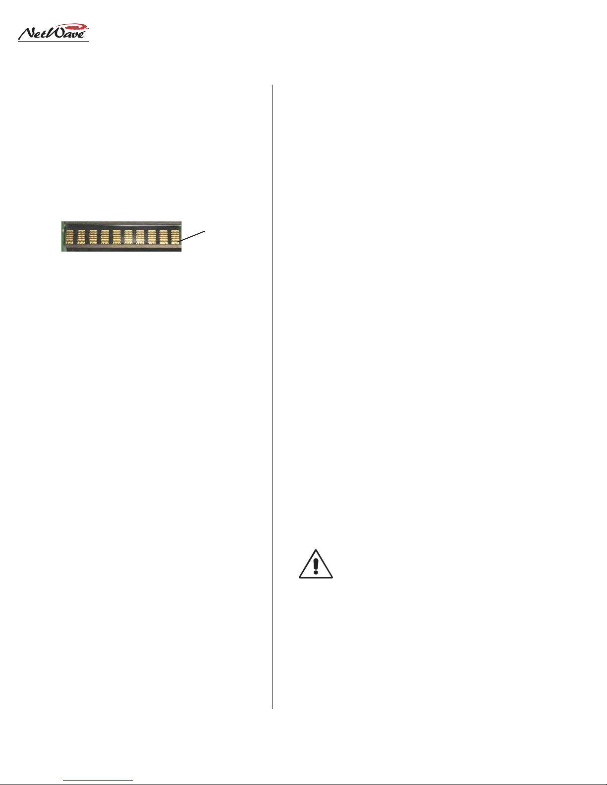
5. Plug the two 10-character displays into the
two DIP sockets. Orient the displays with their
bottom row of connections toward the Next/
Include All labels.
Display
Connections
10-Character Display Orientation
6. Snap the display lenses back onto the panel.
7. Discharge static electricity before removing the
TINI card. Firmly insert the TINI into its connector at a 45 degree angle, then press it down
to lock it in place. The TINI’s bag has a label
with its MAC address. Write the console name
and the two channels this TINI controls in the
space provided on the label as this will be
needed during software configuration.
8. Plug in the two CA T-5 cables from the kit. T he
red
cable plugs into J5. The
blue
cable plugs
into J3.
9. Hold the panel above its slot and plug the
cable into the F ader P anel jack. Plug the
red
blue
cable into the LAN Passthru jack, noting the
jack’s letter (the corresponding lettered jack
on the rear panel will then connect the Dual
Router panel to the VistaMax LAN).
10.Set the panel onto the frame, making sure that
the CA T-5 cables are not pinched by the metal
extrusion while it is fastened to the frame.
11.Connect a straight-thru CAT-5 cable from the
matching rear panel LAN Passthru jack (the
same letter jack as used in step 9) to the VistaMax LAN switch.
12.Use VMCC to set up the new Dual Router
panel. The information written on the TINI’s
antistatic bag label is used during this step.
Quad Meter Package
This option replaces the standard console display with a four meter display . Kits are only available for NetWave-16 and NetW a ve-24 consoles.
The Quad Meter Package includes a new console display housing and another meter board. The
console’s original meter and clock-timer boards
are moved to the new housing, which then replaces
the original dual meter console display.
The Quad Meter P ackage has dedicated displays
for PGM 1, PGM 2 and PGM 3, with the fourth
meter (AUX) being used to display PGM 4 or an
external monitor input.
Because the Quad Meter Package requires extensive frame disassembly , the console power must
be turned off during installation. For installation
instructions, refer to the installation guide that
comes with the package.
REFLECTIVE CONSOLE DISPLAY
The reflector can be inserted into its slot behind the console display at this time—if the best
access to the console connectors is from the rear
of the console. If the best access is from the front,
wait until the wiring is completed before installing the reflector .
The reflector is shipped with protective paper
stuck to both sides. This paper must be removed
before installing the reflector.
NOTE: Handle the reflector by its edges
to prevent scratches and fingerprints.
When the reflector is removed, place it
on a lint-free cloth to prevent scratching the reflective surface. Use a lint-free
cloth dampened with either diluted
dish soap or alcohol, or a damp chamois, to clean the surface.
Two 4-40 screws, on the rear of the display assembly , firmly hold the reflector in place after it is
HARRIS CORPORATION
2-6
Revision A • 6/06
Page 23
2 Installation
Reflector Slot
Reflector Notch
Reflector
Installing the Reflector into the Console Display Slot
Detail: Two rear
panel screws hold
reflector in place
installed into its slot. These screws are shipped
installed and must be removed before the reflector can be inserted into its slot.
Insert the reflector, with its notched edge behind the clock and timer , into the slot. The reflector is designed to sit at a 22° angle toward the
board op. This is assured by the two mounting
screws. They should be installed once all console
connections are finished and the console is ready
for daily use. Before this time the reflector can sit
in the slot without the screws for easy removal.
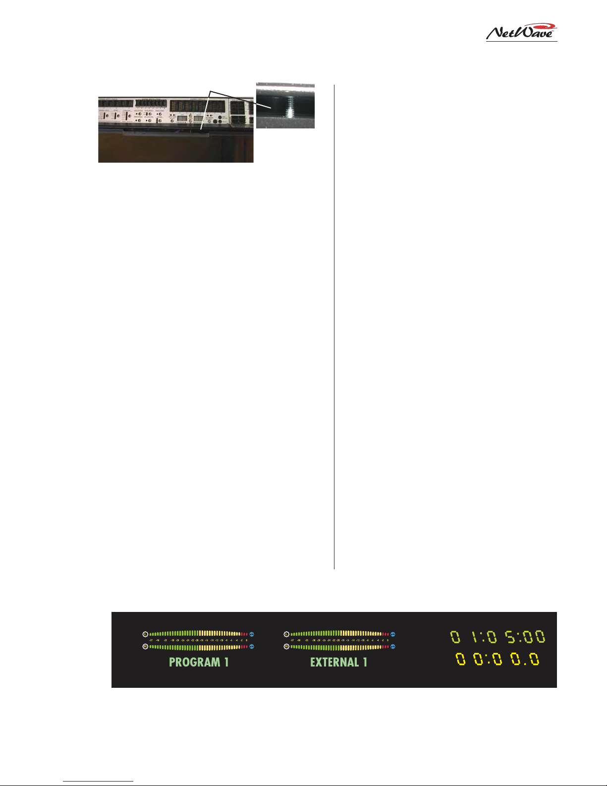
The standard Console Display has two horizontal stereo bargraph meters. Alphanumeric displays
below each meter identify the signal displayed
(PROGRAM 1, PROGRAM 2, etc.). T he standard
meters provide simultaneous level monitoring of
the Program 1 bus on the left-hand meter and
another bus or system signal on the right-hand
Auxiliary Meter , as selected by the Aux Meter buttons on the Monitor panel.
An upgrade option (Quad Meter Package) adds
two more meters so that all four Program buses
can be displayed simultaneously. T his Quad Meter
package upgrade displays Program buses 1, 2 and
3, plus the Auxiliary Meter selection. The Aux
meter functions the same as in the standard meter
configuration.
Various meter, clock and timer parameters are
set using switches on the meter (DS3) and clocktimer circuit boards (DS1). The procedure to
change the switch settings is detailed in the following sections. In summary, here are the various
display parameters that can be changed, with their
factory default setting listed first:
• Meter Display Mode (average plus peak dis-
play or average-only display)
• Blue Over LED turn-on level (-6 dBFS, -4
dBFS, -2 dBFS, 0 dBFS)
• Peak Signal Hold (active or not active)
• Clock Mode (autonomous or slaved to a mas-
ter clock input signal)
• Autonomous Time Display (12-hour or 24-
hour)
• Master Clock Type (ESE or SMPTE)
• Event T imer (display .1 sec or no .1 secs while
running)
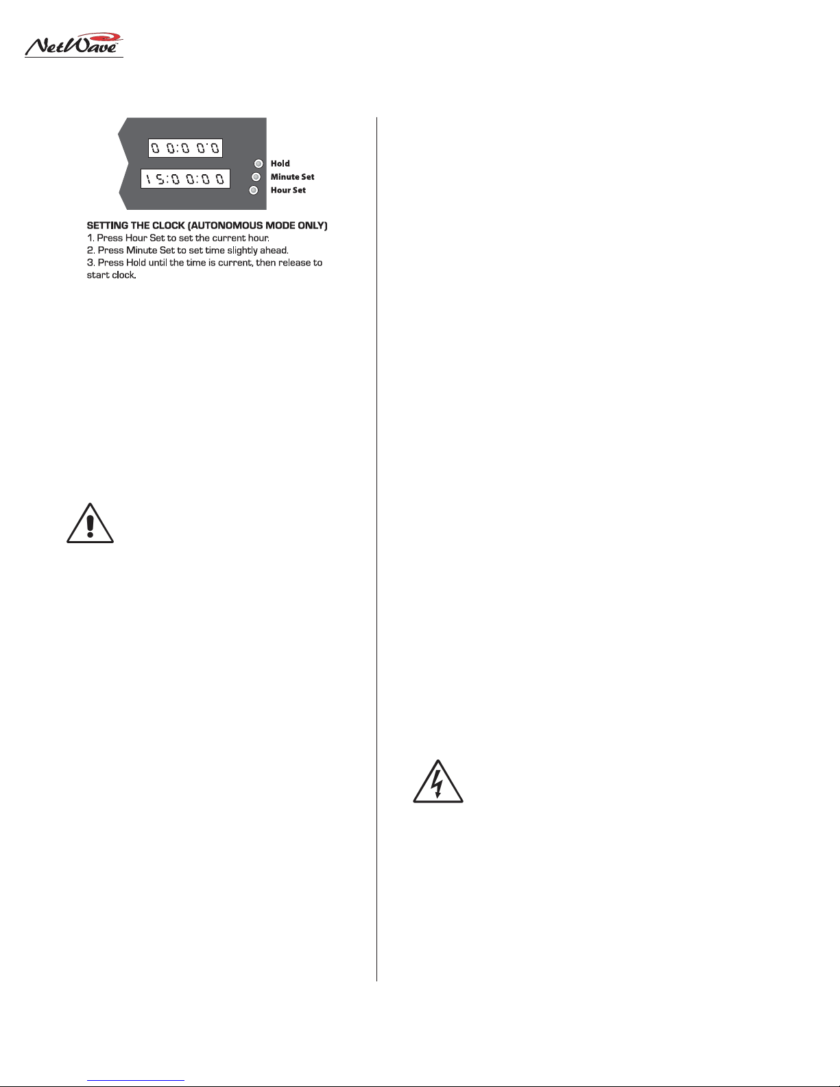
Setting The Clock
When used autonomously (the factory default
setting), a quartz crystal oscillator controls clock
timing. After applying power to the console, the
clock must be manually set to the current time
using the three recessed buttons adjacent to the
clock display (shown on the next page). Use a
blunt-tipped nonconductive object (wooden swab ,
toothpick, etc.) to press the recessed buttons.
PGM 1 Meter Aux Meter
Standard Reflective Display, with
two meters, clock and timer
2-7
HARRIS CORPORATION
Revision A • 6/06
Clock
Event Timer
Page 24
2 Installation
• The Hour Set button (the closest to the board
• The Minute Set button (middle) adjusts the
• The Hold button freezes the clock so it can be
The clock will keep time for about three days
with the console powered off. Beyond this point
the time will have to be reset again when autonomous mode is used.
Removing the Console Display
The console display must be removed from the
frame to change display settings, to connect a master clock or remote timer reset cable or to install
the Quad Meter P ackage.
Each of these activities require accessing the
meter and clock-timer printed circuit assemblies
(PCAs) on the bottom of the console display. The
console should be powered off when removing and
reinstalling the display assembly . Two padded sur-
operator) adjusts the hour display
minute display
manually synchronized to a local time reference. Set the time slightly ahead of the reference time then press Hold. Release Hold when
the time display matches the reference time.
NOTE: When one of the master modes
is selected (see Clock Settings) and the
selected format signal (ESE or SMPTE)
is not present, the clock runs off its internal oscillator. Both display colons
blink to indicate the ESE or SMPTE
timecode is not present or valid.
faces are required for this procedure. To remove
the console display:
1. Flip-up the rear connector cover to access the
two rear corner 4-40 screws that hold the reflector in place. Remove these screws.
2. Lift the reflector out of its slot. Place it on a
padded surface to protect its mirrored surface.
3. Remove the console display cosmetic cover
screws (two or four 4-40 Phillips screws). Remove the cover by lifting it straight up.
4. Set the smoked display window (which was
sandwiched between the display cover and the
main display subassembly) off to the side.
5. Remove the display subassembly mounting
screws (4-40 Phillips) along the front of the
subassembly just above the control panels .
6. To protect the control panels and display sub-
assembly , lay padded material over the top half
of the control panels. Lift the display subassembly up just enough to clear the frame, flip
it forward and lay it facedown onto the padded material. The display subassembly connects to the Monitor & Output board using
two cables. Do not strain these cables while
removing the subassembly and placing it onto
the control panels.
7. Use the illustration on the next page to iden-
tify the switches and connectors on the clocktimer and meter PCAs.
SAFETY NOTE: Touch the metal chas-
sis to dissipate static before adjusting
the switches or plugging in an ESE,
SMPTE or remote timer cable. Do not
touch any components on the PCAs
other than the switches or connectors.
Reinstall the console display in reverse order . Use
care to not pinch any cables between metal parts.
Align the smoked display window holes with the
clock set holes. T he cosmetic co ver holds it in place.
HARRIS CORPORATION
2-8
Revision A • 6/06
Page 25
2 Installation
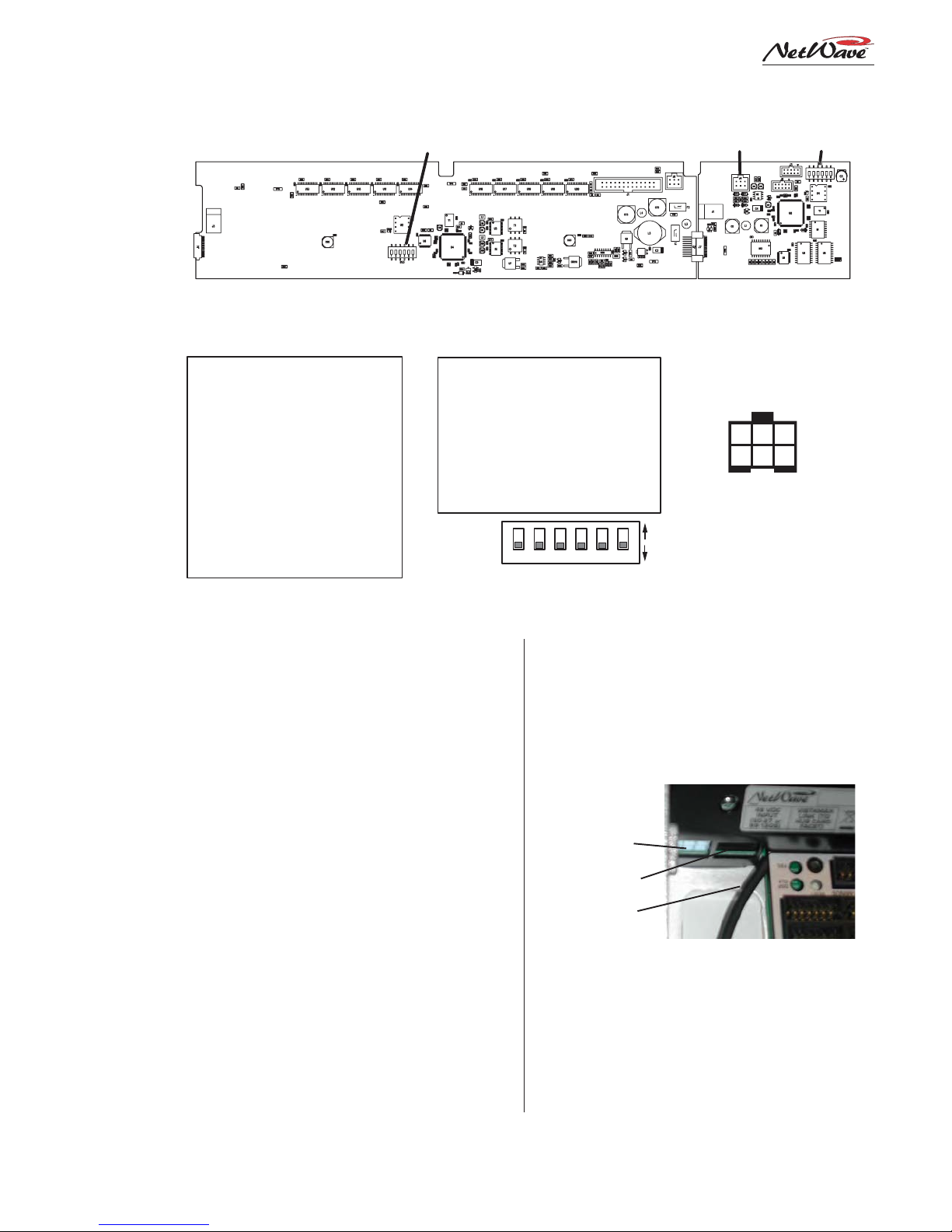
DS3 J4 DS1
METER PCA CLOCK-TIMER PCA
Meter Boards
DS3 Switch Settings
Switch Function: Off / On
1 - Av & peak / average only
2 - 2s peak hold / no hold
3 - Blue LEDs turn on level*
4 - Blue LEDs turn on level*
5 - NetWave / RMXdigital
6 - NetWave / non-mirrored
* Blue Peak LEDs turn on at:
-6 dBFS, 3 and 4 are off
-4 dBFS, 3 is on and 4 is off
-2 dBFS, 3 is off and 4 is on
0 dBFS, 3 and 4 are on
Console Display PCA Setup Switches and Connections
(orientation shown while set onto the control panels)
DS1 / DS3:
Default
settings
are all off
Clock-Timer Board
DS1 Switch Settings
Switch Function: Off / On
1 - .1s displays / .1 off (Timer)
2 - no ESE / ESE master
3 - unused
4 - 12-hour / 24-hour **
5 - no SMPTE / SMPTE master
6 - NetWave / non-mirrored
* active only when 2 and 5
are both set to off
Clock Settings
Clock parameters are set using multi-switch
DS1, located near the upper right corner of the
clock-timer PCA. The default settings are all
switches set to off.
When used autonomously, the clock time can
display 12-hour or 24-hour time. Set DS1-4 to on
to display 24-hour time. This setting is ignored
when a master clock signal is used.
When an ESE TC-89 or TC-90 master clock is
used, set DS1-2 to on. T he ESE signal type is autodetected. When a SMPTE master clock is used,
set DS1-5 to on. If both DS1-2 and DS1-5 are set
on, only SMPTE is valid. An ESE signal will be
ignored.
ESE, SMPTE & Remote Timer Reset
An ESE or SMPTE master clock signal connects to J4, pins 5 and 6. The signal is polarity
sensitive, but can be balanced or unbalanced. Con-
1 2 3 4 5 6
nect the high (center conductor) or + signal to pin
5 and the low (shield) or - signal to pin 6.
J4, pins 3 and 4 are used to connect a cable
that can reset a studio event timer. Pin 3 is the
timer reset output (pulse low on timer reset) and
pin 4 is ground.
DC Input
RJ-45 Link
Cable to J4
J4 (ESE/SMPTE, studio event timer reset) Cable
NOTE: T he wiring to J4 must be routed through a
small chassis opening (next to the RJ-45 Link
connector) before being terminated into the 6-pin
MOD IV housing. Leave sufficient wire length to
plug in J4 while the display is face down over the
control panels.
Clock-Timer J4
(ESE / SMPTE
MASTER CLOCK &
REMOTE TIMER )
6 5 4
3 2 1
1 - TIMER RESET LOGIC, IN
2 - GROUND
3 - TIMER RESET LOGIC, OUT
ON
4 - GROUND
OFF
5 - ESE or SMPTE INPUT +
6 - ESE or SMPTE INPUT -
2-9
HARRIS CORPORATION
Revision A • 6/06
Page 26
2 Installation
Event Timer Settings
The event timer displays time in minutes, seconds and tenths of seconds. T he only timer setting
(DS1-1) sets whether the tenths of seconds digit is
displayed while the event timer is running .
When set off (the factory default) the tenths are
always displayed. When DS1-1 is set on, the tenths
of seconds are not displayed while the timer is
running, but are displayed while the timer is
stopped or is being held.
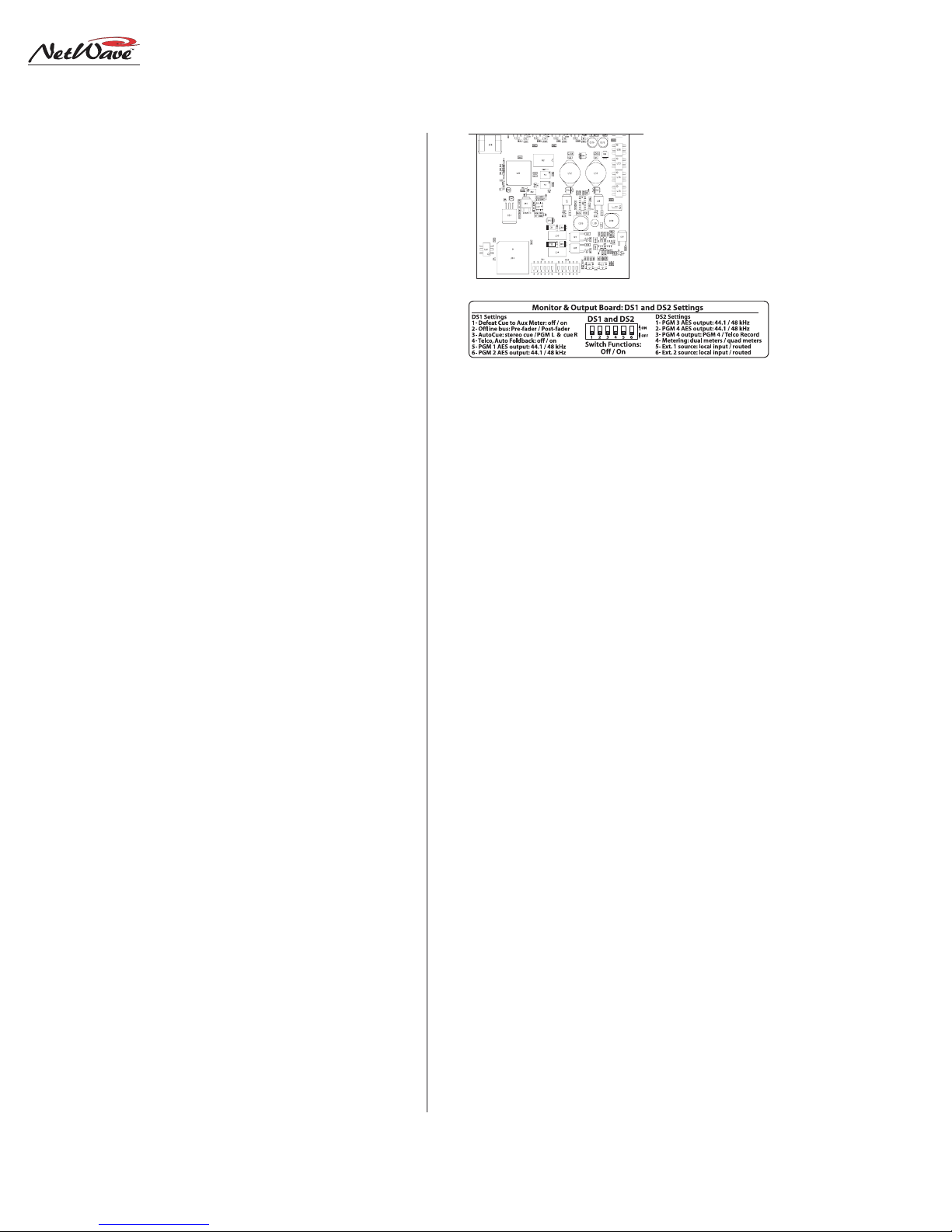
Exposed portion of
the Monitor & Output
board, below the
Monitor panel
DS1 DS2
Monitor & Output Board, Multi-Switch Settings
Meter Settings
The PGM 1 and Aux meter parameters are set
using multi-switch DS3 (shown on page 2-9). The
Quad Meter Package adds a second meter board.
The left-hand board’ s DS3 settings affect the first
pair of meters (PGM 1 and PGM 2) and the righthand meter board’s DS3 settings affect the PGM
3 and Aux meters. Typically the two meter boards
would be set to the same settings. The DS3 factory settings are all switches set to off.
To turn off the peak displays and to show only
the average meter lev els, set DS3-1 to on.
To have the Peak indicators decay immediately,
switch DS3-2 to on.
To change the level where the Blue LEDs turn
on: set DS3-3 and DS3-4 to off to turn on the Blue
LEDs at -6 dBFS; set DS3-3 on and DS3-4 off to
turn on the Blue LEDs at -4 dBFS; set DS3-3 off
and DS3-4 to turn on the Blue LEDs at -2 dBFS.
DS3-5 and DS3-6 must be left set to off for NetWave consoles.
MONITOR & OUTPUT BOARD SETTINGS
The Monitor & Output board has two multiswitches to assign various parameters to the Monitor & Output board outputs. The factory default
setting for all switches is off.
To access the switches, the Monitor panel must
be removed from the frame. Follow the directions
on page 2-4 to remove the panel.
DS1 and DS2 Settings
Multi-switches DS1 and DS2 are at the front
edge of the Monitor & Output board, hidden below the Monitor panel in normal use. Here is what
each switch does:
DS1-1 affects the Aux meter display. When off
the cue level is displayed while cue is active. When
set to on, the A ux meter does not display cue.
DS1-2 affects the Offline bus signals. When off,
Offline signals are derived pre-fader . When on, the
Offline signals are post-fader .
DS1-3 affects the operator headphone output
when AutoCue is active. When set off, cue is fed to
the headphones in stereo (typically used for production rooms). When set to on, a split feed (monitor to one ear, cue to the other ear) is sent to the
headphones (typically used for on-air consoles).
DS1-4 affects Telco channel operation. When set
to off, the mix-minus source (the winking bus assignment button) is not affected by turning the
Telco channel on or off. When set to on, the Auto
Foldback function is activ ated. T he mix-minus output automatically switches between Offline (Telco
channel off) and the lowest selected program bus
(Telco channel on). When Offline is not lit on the
Telco channel, no mix-minus audio is heard while
the channel is off, except for talkback to that T elco .
The next four switches (DS1-5, DS1-6, DS2-1
and DS2-2) set the sample rate outputs for the
HARRIS CORPORATION
2-10
Revision A • 6/06
Page 27
NetWave-16, Fram e Con f ig u r at i o n
2 Installation
99-1420 DSP & I/O card *
Reflective Console Display
Cue Speaker PGM 1 Meter AUX Meter Clock and Timer
PRE99-1423 NetWav e Dual Fader
panels take up two input slots.
Unused input slots are covered
with PRE90-2125 Dual Blanks.
Input Slot 3
Input Slot 2
Input Slot 1
NONO
TES:TES:
NO
TES:
The console model (NetWave-8, -16,
NONO
TES:TES:
Input Slot 5
Input Slot 4
Input Slot 7
Input Slot 6
Input Slot 8
Input Slot 9
-24) equals the number of input slots. One Monitor &
Output card and one Monitor Control panel is supplied
with each frame. Each DSP & I/O card has DSP, audio
inputs and logic I/O for eight input channels, thus
NetWave-8 has one DSP card, NetWave-16 has two DSP
cards, and NetWave-24 has three DSP car ds.
Unpopulated input slots are covered by NetWave Dual
Blank panels (90-2125).
99-1420 DSP & I/O card *
Input Slot 10
Input Slot 12
Input Slot 11
Input Slot 14
Input Slot 13
Input Slot 15
Input Slot 16
User-installed NetW ave console options:
• 99-1423 Dual Fader Panels (two additional panels
can be added to NetWave-16, three to NetWave-24)
• 99-1424 Dual Router Kit (adds VistaMax system
source selection to any Dual Fader panel)
• 99-1425 Link Activation Kit (adds a bidirectional
console connection to a VistaMax or Envoy Hub card)
• 99-1990-16Q Quad Meter Package for NetWave-16
• 99-1990-24Q Quad Meter Package for NetWave-24
99-1421
(one standard)
Studio Monitor Controls
with Aux Meter, Control Room and
99-1422 NetWave Monitor Control Panel
PGM 1, PGM 2, PGM 3 and PGM 4 digital outputs. When set to off, the sample rate is 44.1 kHz.
When set to on, the sample rate is 48 kHz.
DS2-3 selects the signal used for the local PGM
4 analog connector. When set to off, PGM 4 is
output. When set to on, Telco Record is output
instead. T his setting does not affect the digital PGM
4 output or the PGM 4 VistaMax system signal.
DS2-4 is set to on when a Quad Meter Package
is installed. For the standard two meter display it
must be set to off.
DS2-5 and DS2-6 set which source feeds the
External 1 and 2 monitor selectors. When set to
off, the local external audio input is used. When
set to on, the signal is routed from a VistaMax
system. The on setting should only be used when
the Link Activation kit has been installed.
HARRIS CORPORATION
NETWAVE CONTROL PANELS
The NetWave’s main components are identified
in the illustration, above. There are four types of
control panels (Dual F ader, Dual Router , Monitor
and Dual Blank); two types of cards (Monitor &
Output and DSP & I/O); and two display PCAs
(Dual Meter and Clock-T imer).
Each slot, or control panel frame position, is
1.6" wide. The Monitor panel consumes three slots
while all of the other panels use two slots. There
are sixteen input slots on a NetWave-16, as shown
above, so up to eight Dual Fader or Dual Router
panels can be installed. The NetWave-16, as
shipped from the factory, includes six Dual Fader
panels installed into slots 1-12. Slots 13-16 are
covered by two Dual Blank panels .
Additional Dual Fader panels (99-1423) can be
installed into slots 13-16 at time of installation or
2-11
Revision A • 6/06
Page 28

2 Installation
DSP & I/O CARD FADER CONNECTIONS
(SLOT POSITIONS ARE NUMBERED FROM LEFT TO RIGHT)
FADERS 1 - 8 FADERS 9 - 16*
FADERS 1 - 8 FADERS 9 - 16 FADERS 17 - 24
* AS SHIPPED FROM THE FACTORY, FADER POSITIONS 13 - 16 ARE UNPOPULATED ** AS SHIPPED FROM THE FACTORY, FADER POSITIONS 19 - 24 ARE UNPOPULATED
any time afterwards. If purchased with the console, they will be separately boxed and are installed
in place of the Dual Blank panels.
This also holds true for the NetWave-24, which
ships with nine Dual Faders (in slots 1-18) and
three Dual Blank panels in slots 19-24.
DUAL FADERS AND DSP & I/O CARDS
Four Dual Fader panels connect to each DSP &
I/O card, as illustrated above. Each connects to
an RJ-45 jack labeled by their channel assignments
(i.e., F ader P anel 7 & 8). These identify which two
channels are serviced by that jack. The panels get
power and send/receive control signals from these
jacks using short red CAT-5 cables. A NetWave-8
frame has four cables, a NetWave-16 has eight and
a NetWave-24 frame has twelve cables.
The optional Dual Router Kits add a second
CAT-5 cable to connect the kit’s TINI card to the
VistaMax LAN. Because of space constraints, two
special flat CAT-5 cables are included with each
Dual Router kit.
The Dual F ader and LAN pass-thru RJ-45 jacks
are located below each Dual Fader panel’s rear
mounting bracket. A chassis label identifies each
jack as to its use.
Audio Inputs and Logic I/O
Each DSP & I/O card has eight analog inputs,
eight digital inputs and eight Channel Logic I/O
connectors, as shown on page 2-13. W hich physical input (analog or digital) is assigned to the A
FADERS 1 - 8
**
(MONITOR &
OUTPUT CARD)
CONSOLE: HARRIS P/N
NETWAVE-8: 99-1600-08
NETWAVE-16: 99-1600-16
NETWAVE-24: 99-1600-24
and B channel sources; its mode (stereo, left, right,
mono); its function (line, CR mic, Studio mic, T elco
1, Telco 2); whether the logic I/O is active for the
A or the B source; and several other parameters,
are all assigned through a common group of channel setup buttons and LEDs on each DSP & I/O
card. These controls are covered in the next section (Setup Controls).
Here are definitions for several NetWave signal
and control panel terms used in this manual:
Channel slot
(1 to 8, 1 to 16 or 1 to 24)
refers to the left-to-right frame positions, as viewed by a board operator,
where Dual Fader, Dual Router or Dual
Blank panels can be installed. T hese are
equivalent to the Fader numbers shown
in the illustration, abov e.
Channel strip
refers to the set of physical channel controls. There are two
channel strips per Dual Fader or Dual
Routerpanel.
Source
refers to the two operator selected channel sources (A, B) a vailable
on each Dual Fader channel strip.
Local Inputs
or
I/O
refers to the physical audio and logic connectors on each
DSP & I/O card.
Channel
refers to a channel strip on a
Dual Fader or a Dual Router panel.
HARRIS CORPORATION
2-12
Revision A • 6/06
Page 29

DSP & I/O Card Setup Controls
2 Installation
Setup Co n tro ls
Each DSP & I/O card has a common group of
setup controls, shown above, to separately assign
the parameters used by the A and B sources on
the eight channels (on four Dual Fader or Dual
Router panels) that plug into that DSP & I/O card.
A Setup Stylus Tool (70-160) is included with
the console to press the recessed buttons. Any
blunt-tipped nonconductive object (wooden swab ,
toothpick, etc.) could alternately be used.
The following sections cover using the DSP &
I/O card setup controls to configure the channel
parameters. Note that these are typically not set
until after the console has been wired since parameter changes take effect immediately so that
the active signal and level can be confirmed using
the console display and monitor outputs.
The active channel and source on the setup controls is identified on the active channel display and
on the Dual Fader panel by the blinking A or B
indicator. This allows the input source (analog,
digital or network) to be monitored on the active
channel to ensure the correct signal is selected and
that the levels and logic settings are proper .
Setup Modes
Four modes are used:
Sleep Mode
erations. T he LEDs and displays are not lit up
and only certain buttons are active.
T he panel automatically s witches into
Mode
Alternately , the panel can be forced into
Mode
LEDs turn off (about three seconds).
Parameter Set Mode
parameters, adjust parameters and store parameters into nonvolatile RAM. From
Mode
Down to activate this mode. The stored parameter settings are recalled for each channel
source, as shown by the lit parameter LEDs
and trim displays. The set of parameters for
each source can be changed as required and
then stored by pressing Store. If changes are
made that should not be stored, pressing Chan-
nel Up or Down (to change to another channel source), cancels the parameter changes.
is used during normal console op-
ten minutes after the last button press.
by pressing and holding Store until the
is used to view channel
, press Store, Channel Up or Channel
Sleep
Sleep
Sleep
NOTE: Use care when changing parameters on on-air consoles as
changes could affect on-air performance.
Parameter Copy Mode
mode where stored parameter settings are not
recalled when the channel source is changed.
Instead, this mode allows one group of parameters to be set up and then stored to multiple
2-13
HARRIS CORPORATION
Revision A • 6/06
is an alternate setup
Page 30

2 Installation
sources. The Changes Pending LED continuously blinks to identify this mode is active.
Typically, this mode is only used with inputs
like mics, computer pla yback systems and CD
players, where several inputs will all use the
same, or very similar, parameter settings.
To activate this mode: from
Sleep Mode
press and hold Option while pressing Chan-
nel Up (
). Use a toothpick or other nonconductive tool to press the second button when
two Setup Stylus tools are not available.
Adjust the parameters as required; select a
channel and source that uses those settings;
press Store to save the settings. Select other
channel sources that use the same settings and
again press Store each time to save the parameters on as many channel sources as required. To exit, on the last channel source using those parameters, press and hold Store until all setup LEDs turn off.
each channel and source are recalled as the channel and source are selected. The Channel Display
shows which channel (from 1 to 8) and source (A
or B source LED is lit) is active. The channel strip’ s
A or B label also flashes to indicate the active channel. On Dual Router panels, both source LEDs
,
light since those channels only have one source.
The stored parameters for the active channel
source are recalled from memory and displayed
on the parameter LEDs and the two trim displays.
In
Parameter Set Mode
, changing any parameter causes the Changes Pending LED to blink. To
save the updated parameter settings for that channel source to memory, press Store. The Changes
Pending LED turns off to indicate the settings were
saved. To cancel parameters changes when the
Changes Pending LED is blinking, change to another channel source by pressing Channel Up or
Channel Down. Returning to the previous channel source will again load the saved parameters.
Test Mode
activate. From
also requires two Stylus tools to
Sleep Mode
, press and hold Op-
tion while also pressing Channel Down (
In this mode one set of parameter settings are
assigned to all eight channels for test purposes
and no settings can be stored.
The operation of this mode and other test
modes are detailed in the chapter on Servicing the NetWave console.
Set-Up Controls
The sixteen momentary push-buttons, three
7-segment displays and twenty-nine LEDs on each
DSP & I/O card (as shown on the previous page)
are used to view, set and store the parameters for
each source on the eight channels connected to
that DSP & I/O.
The controls are normally used in
Set Mode
, where the stored parameter settings for
Parameter
NOTE: Changes to parameter settings
immediately affect the active channel
).
so that the input selection, mode selection, function settings , logic settings
and level trim settings can be actively
monitored during parameter setup.
Use caution when changing parameters on on-air consoles.
Here’s a summary of the functions for each setup
button, LED and display:
Store Button—This is a multifunction button: with
the panel in
Store switches the panel into
eter Set Mode;
Sleep Mode
, pressing
Param-
when the Changes
Pending LED is blinking, pressing Store writes
the current source parameters into nonvolatile
memory; and pressing and holding Store forces
the panel into
Sleep Mode
from any other mode.
HARRIS CORPORATION
2-14
Revision A • 6/06
Page 31

2 Installation
Changes Pending LED—This LED blinks in the
Parameter Set Mode
to indicate a parameter has been changed and has not
yet been stored. Pressing Store turns
the LED off to indicate the changes were stored.
In
Parameter Cop y Mode
, this LED blinks rapidly to indicate the mode. Pressing Store turns the
LED off momentarily to indicate that the changes
were stored.
Channel Up & Channel Down Buttons—In
Mode
eter Set
these two buttons step
Param-
through the eight channels and their
A and B sources in order to view the
stored parameters for each source. In
Parameter Copy Mode
, the two buttons also step
through the channels and sources, but the stored
parameters are not recalled since that mode allows one set of parameters to be stored to multiple sources.
Active Channel & Source Indicators—The active
channel number is shown in the 7-segment Channel display and the active
source is indicated by the lit A or B
nel Down
LED. Press Channel Up
to step sequentially through the chan-
or Chan-
nels and sources. The channels wrap around
(Channel Up from source 8B goes to source 1A
and vice versa). The decimal point lights to indicate
Parameter Copy Mode
is active.
Input Select—Sets the audio input (local analog,
local digital, network audio , network
audio with logic) assigned to the active channel source. The two Net A udio selections are only available
when the console’s
taMax Linked
VistaMax Enabled
and
Vis-
labels are lit on the Monitor panel.
Input Mode—Sets how the selected input audio is
fed to the channel strip.
Stereo
is the
default setting for stereo sources like
CD players.
Mono
is typically used for
news or mono AM broadcast applica-
tions. It sums a stereo input to a mono signal that
is applied to both left and right.
The
Left
and
Right
selections are typically used
with mic preamps. These settings allow two mics
to be assigned on the same channel to the A and
B sources. Typically the
the A source and the
Left
input is assigned as
Right
input is set as the B
source. One typical application is to connect control room guest mics to the left inputs and set them
as the A sources , while studio guest mics are connected to the right inputs and are assigned as the
B sources on the same channels.
Input Function—Defines the type of signal con-
nected to the selected input. The setting may affect the monitor outputs,
mix-minus outputs, and v arious Logic
I/O signals.
With no LEDs lit, the signal is defined as a line
input device (i.e., CD pla yer , MD player, computer
playback system, Shortcut, Instant Replay, etc.).
The channel does not mute any monitor output
when on. If logic is active, the channel output logic
is start and stop pulses while the channel input
logic is on, off, ready and cue.
When CR MIC is lit, the signal is defined as a
control room mic. W hen the channel is turned on,
the CR Monitor output mutes and the control room
warning command is activated. If logic is active,
the output logic is on tally and off tally and the
input logic is on, off , cough and talk to studio.
When CR MIC TLK SRC is lit, the signal is also
defined as a control room mic, with the same
muting and logic features as the CR MIC selection. But, in addition, this signal is identified as
the talk mic source for console talkback. Multiple
2-15
HARRIS CORPORATION
Revision A • 6/06
Page 32

2 Installation
mics can be set as control room talk sources, but
typically only the board operator mic, and possibly a producer mic, are set to this function. Other
control room mics can talk to the studio by using
a mic control panel with a talkback button.
When STU MIC is lit, the signal is defined as a
studio mic. When the channel is turned on, the
studio monitor output mutes and the studio warning command is activated. If a mic control panel
with talkback button is used, then that mic position can talk to the control room.
When TELCO 1 or TELCO 2 is lit, it indicates
the input signal requires a mix-minus signal from
the console. These settings are used with Telco
hybrids, ISDN connections, satellite transceivers
and other two-way devices. Only one console channel source can be set as T elco 1 and only one console channel source can be set as Telco 2.
Logic Active—Sets whether the channel logic I/O
connector is active for that source.
When lit, the channel’s logic I/O
connector is active. When unlit, the
logic connector is not active for that source. Typically, only A or B is set for Logic Active on any
channel.
Timer Reset—W hen lit, indicates the channel strip
will send a timer reset command to
the Event Timer when it is turned
on. When unlit, no timer reset command is issued. In order for the timer reset commands to reach the Event Timer, the Auto button
on the Monitor panel must be lit.
Start/Stop Pulse Generation—Affects the chan-
nel logic start and stop pulses gen-
erated for Line and Telco channel
logic. There are four conditions:
both LEDs off; Local on and Multi off; Local off
and Multi on; and both Local and Multi on.
With both LEDs off, one start or stop pulse is
generated when the channel on/off state changes
by pressing Channel On/Off or when receiving
remote logic channel on and off commands.
With the Local LED on and the Multi LED off,
a start or stop pulse is only generated when the
channel status is changed by pressing Channel On
or Channel Off. The channel can still be turned on
and off remotely , but no start or stop pulse will be
generated.
With the Multi LED on and the Local LED off,
a start pulse is generated anytime Channel On is
pressed or a start command is received. Likewise,
a stop pulse is generated anytime Channel Off is
pressed or a channel off command is received. No
channel state change is required to generate another start or stop pulse.
With both the Multi and Local LEDs on, a start
pulse is generated anytime Channel On is pressed
and a stop pulse is generated each time Channel
Off is pressed. Remote channel on or off commands
do not generate any pulses.
Off Button Lighting—When unlit (the standard
setting), the Off button lights up
whenever the channel is off. When
lit, the remote logic command Read y
controls the lighting of the channel Off button.
Typically, this setting is lit for CD players and
other peripheral devices that can control a
channel’s Off button light to indicate play status.
If the peripheral is not ready (e.g., no CD loaded),
the channel off button is not lit. When the peripheral is ready (e.g., a CD is loaded and cued), then
the off button is lit. After the peripheral finishes
(e.g., the CD track has played) the off button winks
to indicate the event has completed.
HARRIS CORPORATION
2-16
Revision A • 6/06
Page 33

2 Installation
Fader Start—When unlit (the standard setting),
the channel fader position has no
effect on the channel on/off status.
When lit, mo ving the fader turns the
channel on as the fader is moved up from full off.
The channel is turned off when the fader is returned to full off.
The channel on and off buttons and the remote
channel on and off commands are not affected by
the fader start setting.
Option—The Option button is used in combina-
tion with other buttons to put the
panel into test or special setup
modes. The three LEDs may indicate when a special mode is active.
When 1 is lit, it indicates the panel is in the
Copy Parameter
mode, where one set of param-
eters can be saved to multiple channel sources.
When 2 is lit, it indicates the panel is in the
setup test
mode. In this mode all eight channels
use the same set of parameters (which can be adjusted but not stored). This mode is used to quickly
determine if all inputs and channel strips are working properly .
Input T rim Controls—Each local analog and digi-
tal input can have its
left and right signals
separately trimmed,
in one dB steps, by up to +/-15 dB.
The Input T rim Select button sets which input—
analog (A) or digital (D), is active and which signal—left or right, is selected for trimming . T he active signal is identified by the lit A or D indicator
and by the lit Trim Active decimal point in the
Trim display.
Press the Level Up
or Level Down button
to raise or lower the active signal’s level in 1 dB
steps. When the active source’s channel strip is
turned on and assigned to a bus, then the console
meters can be used to adjust the level since the
level changes take place immediately.
Network Source—This function is only active
when the console’s VistaMax Link is
active. One input on each channel—
either analog (A) or digital (D), is set
as a VistaMax source. The selected
input signal goes to the VistaMax system via the
Link cable. These signals are available for selection like any other VistaMax source signal. This
setting does not affect any local uses of the selected signal.
Refer to the NetW ave Quick Guide and to pages
2-27 to 2-29 for the parameters settings used by
the most common type of signal inputs.
Channel Source Labels
Dual Fader panels have an A/B label on each
channel. One blank source label (80-2132) for each
input slot is supplied in the console installation
kit. Use a Brother P-Touch® labeler, with 1/4" clear
with black lettering tape, to create custom source
labels that can be stuck onto these blank source
labels. Up to five characters are possible per source
name when the smallest lettering size (Size 1) is
used.
A source (Yellow) B Source (red)
Silo Divider
Custom Source Name Label
To replace the source label, pry up on the
smoked polycarbonate display lens from the outside (the lens has two snap tabs along the top and
bottom to hold it in the panel). Remove the A/B
label from the rubber silo. Insert the custom label
in its place. Make sure the label is firmly held in
the silo’s recess before snapping the display lens
back onto the panel.
2-17
HARRIS CORPORATION
Revision A • 6/06
Page 34

2 Installation
Cabling and Wiring
All user connections are made on plug-in connectors along the rear of the console. The connectors are hidden in normal operation by a rear flipup cover that extends across the console.
To access the connectors, the co ver can be completely removed by lifting it straight up when
closed, or it can be flipped open by either lifting it
from the front edge or by pressing in on the vertical section at the back. The cover sits on two roll
pins that extend from the side panels. It flips open
toward the rear.
Note: The cover is typically removed
during installation to ease connector
access. To prevent scratches, set the
painted cover on a padded surface.
• Crossover CAT-5e/CA T-6 cable to connect the
VistaMax Link connector to a VistaMax frame
• Straight-thru CA T-5 cables to connect the Dual
Router kits to a VistaMax system LAN switch
WIRE PREPARATION
All NetWave audio and logic wiring terminates
in AMP MOD IV receptacle contacts. Stranded
wires of 22 to 26 A WG , with insulation diameters
of .040 to .060 inch, can be used with the MOD
IV receptacle contacts.
Insulation
Crimping Barrel
9/64” [3.57 mm]
Wire Crimping
Barrel
REQUIRED CABLES AND WIRE
The following types of wire and cable are rec-
ommended for use with NetWave consoles:
• Analog audio connections use two-conductor ,
stranded, insulated, shielded cable using a
separate shield drain wire (equivalent to
Belden 8451, 9451 or 8761)
• AES/EBU connections use 110 ohm two-conductor, stranded, insulated, foil-shield cable
containing a separate shield drain wire
(equivalent to Belden 1800B)
• Logic control uses stranded, 22 AWG, multiple-conductor, non-shielded, jacketed cable
(equivalent to Belden 9423, 8457 or 9421).
The number of conductors required is determined by the application. Typically, cables
with five or eight wires are most often used
for constructing logic cables since, ev en though
there are twelve or fourteen pins on the logic
connectors, only a handful are typically connected for any given application.
HARRIS CORPORATION
Properly
Crimped Contact
AMP MOD IV Receptacle Contacts
F ollow these steps for audio wire preparation:
1 Strip the cable insulation jacket and foil shield
back 1½" [38.10 mm].
2 Remove the foil shield and sleeve the drain
wire with 20 AWG Teflon sleeving. Leave
9/64" [3.57 mm] of the drain wire exposed.
3 Cover the cut end of the jacket with 3/4"
[19.05 mm] of heat-shrink tubing. Shrink this
tubing, centered on the jacket cut end, to hold
the drain wire sleeving in place.
4 Strip the signal wire insulation back 9/64"
[3.57 mm].
5 Crimp the receptacle contact onto the wire
and insulation.
2-18
Revision A • 6/06
Page 35

AMP MOD IV
Receptacle Contacts
3/4” [19.05 mm]
Shrink Tubing
Teflon Sleeving
Cable ID Tag
over drain wire
Audio Wire, ready for insertion into an
AMP MOD IV connector housing
AA
udio Cudio C
able Sable S
A
udio C
AA
udio Cudio C
able S
able Sable S
hielding Nhielding N
hielding N
hielding Nhielding N
otot
e:e:
ot
e: To follow recom-
otot
e:e:
mended grounding procedures, the drain wires
must be sleeved with Teflon sleeving and heat
shrink tubing must cover all cable jacket cut ends
to insulate the shield wiring.
Logic control cables are fabricated in a similar
manner to the audio wiring. Strip the jacket insulation back 1½" [38.10 mm], sleeve the cut end
with 3/4" [19.05 mm] of shrink tubing and strip
the insulation from each wire 9/64" [3.57 mm].
CRIMP TOOL OPERA TION
A ratcheting AMP crimp tool with contact holder
d
(70-126) is included with each RMX
console and with each VistaMax card frame.
or BMX
2 Installation
To use the ratcheting crimp tool:
1. Insert the contact into the contact holder with
the barrel openings up. Typically, the middle
holder is used (20 - 24 AWG wire). Flip the
holder up so it magnetically latches against
the crimp tool. The end of the insulation barrel should be about 2 mm from the end of the
die. Close the tool handles one click (only until the anvil holds the contact in place, as shown
in the cutaway view, below).
2. Insert the prepped wire into the contact until
the insulation hits the tool’s stop. Hold the
wire in place while squeezing the tool handles
to crimp the contact onto the wire and insulation. The tool handles automatically release
and spring open after the crimp cycle is complete.
Contact Holder,
Printed
Side of
Die
d
Wire
Crimp
Tool
snapped against
Crimp Tool
AMP MOD IV
Receptacle
Contact
If a tool is not already on-premises, one is included
in the optional 76-1901 NetWave/SMXd Tool Kit.
The MOD IV tool crimps both the insulation and
the wire barrels on the MOD IV receptacle contact
in one crimp.
AMP MOD IV
Contact
Crimp Tool
HARRIS CORPORATION
2-19
Revision A • 6/06
Anvils
Insulation
Stop
Crimp Tool — Cutaway View
After all contacts on a cable are crimped, insert
and lock the contact into the appropriate connector housing following the pinout diagrams found
on page 2-20 (for audio) and 2-23 (for logic).
Insert the receptacle contact into the housing
with its locking tab side toward the locking tab
slots on the connector housing. A slight click can
be heard when the contact’s locking tab springs
up into the locking tab slot.
To remove a contact from a housing, the 70129 Contact Removal Tool (also included in the
Page 36

2 Installation
76-1901 tool kit) is required. Insert the tool’s tip
into the locking tab slot and press the locking tab
down while lightly pulling on the wire to remove
the contact from the housing.
Con tact Remova l Tool
Locking Tab
Slots
Locking Tab
Receptacle Contact,
Insertion & Removal Detail
AUDIO CONNECTIONS
Analog and digital audio connections take advantage of the three-pins per row design of the
MOD IV housings. Three-pin housings are used
for digital connections and six-pin housings are
used for analog connections.
the peripheral devices directly to the patch bay.
Normal these signals to the appropriate analog
inputs.
Likewise, the NetW av e’s analog outputs may be
routed through a patch bay normalled to standard peripherals such as analog on-air processing
gear , recorders, telephone hybrids, etc.
Each analog input is designed for line level (+4
dBu). Each input can be level trimmed (by up to
+/-16 dB) so that unbalanced -10 dBv devices can
be directly connected to the console. Note that microphones must be separately preamplified and
processed before being connected to the console.
Stereo Analog Audio Connections
Line Input or Output — 6-Pin Housing
Pin Signal Description
1 Shield for the left channel
2 Low (-), left channel
3 High (+), left channel
4 Shield for the right channel
5 Low (-), right channel
6 High (+), right channel
Digital & Analog Audio Connectors
1 2 3
3-pin Digital
connector
Pin numbering, wire insertion end view
Audio wiring has this orientation:
• Shields connect on pins 1 and 4
• The audio low wires, typically black,
connect to the middle pins (pins 2 and 5)
• The audio high wires, typically red,
connect to pins 3 and 6
When inputs come from mono sources like mic
preamps, two separate signals ma y connect to each
6-pin connector to maximize connector usage.
6 5 4
321
6-pin Analog
connector
Analog Connections
There are no analog interstage patch points in
the NetWave console. To use the console with a
patch bay, connect line level analog outputs from
HARRIS CORPORATION
Two Mono Analog Connections
Line Input or Output — 6-Pin Connector
Pin Signal Description
1 Shield for signal 1
2 Low (-) for signal 1
3 High (+) for signal 1
4 Shield for signal 2
5 Low (- ) for signal 2
6 High (+) for signal 2
Digital Connections
Three-pin digital inputs accept AES-3 (AES/
EBU) compatible signals with sample rates of 25
to 50 kHz. Each digital input goes through sample
rate conversion (the console’ s internal sample rate
is 48 kHz). In most cases, digital inputs can also
accept unbalanced S/PDIF signals. Refer to Unbalanced Connections on the next page for details.
AES/EBU Digital Inputs & Outputs
Pin Signal Description
1 Shield (connects directly to the chassis)
2 Low (-)
3 High (+)
2-20
Revision A • 6/06
Page 37

2 Installation
Each digital output is an AES-3 compatible signal. AES-3 outputs cannot connect directly to an
S/PDIF input. To do this requires a signal translation interface.
UNBALANCED CONNECTIONS
Although all analog inputs and outputs are
active and balanced, unbalanced consumer or
“semipro” equipment can be connected to the console. For best results, connect an unbalanced device through an IHF-PRO match box and keep
the unbalanced cable lengths as short as possible.
If a match box is not available, connect an unbalanced device directly to a NetWave input using the following illustration.
Connecting an Unbalanced Stereo Device
to a NetWave Analog Input
From th e
Unbalanced
Device
R
L
Shields
When an unbalanced device must be connected
to a NetW av e balanced analog output, and an IHFPRO match box is not available, do not tie the
low (-) and shield pins together to “unbalance” the
signal. The low output pin must always be left floating when unbalancing a NetW a ve output, as shown
in the following illustration.
Connecting an Unbalanced Device
to a NetWave Analog Output
(Nominal Output is -2 dBu)
Console
Balanced
Output
36
25
14
(Make no connections to pins 2 & 5)
Console
Balanced
Input
36
25
14
To the
Unbalanced
Device
L
R
Shields
HARRIS CORPORATION
2-21
S/PDIF Signals
Digital devices with only an S/PDIF digital output can connect to a NetWave input, but only if a
249 ohm resistor is used to impedance match the
S/PDIF cable. Install the resistor on the MOD IV
housing per the following illustration.
An unbalanced-to-balanced line transformer can
alternately be used to interface an S/PDIF signal.
Connecting an S/PDIF Device to
a NetWa ve AES/EBU Input
From
S/PDIF
Device
Signal
Shield
249 ohm resistor
Console
AES/EBU
Input
3
2
1
Note 1: A signal conversion interface must be
used to connect an AES/EBU output to a S/PDIF
input.
Note 2: Some S/PDIF signals may not work with
the NetW av e’s inputs, even with the additional load
resistor or a transformer , because of nonstandard
levels or protocols in the S/PDIF product.
NETWAVE SAMPLE RATE
NetW ave uses the professional audio sample rate
of 48 kHz for all its internal audio mixing and
routing. Each digital input has an integral sample
rate converter to convert incoming sample rates
from 25 to 50 kHz to the console’s internal 48
kHz sample rate.
The console’s digital outputs are normally
sample rate converted to 44.1 kHz, but each can
be set for 48 kHz output through settings on the
multi-switches on the Monitor & Output board
(page 2-10 covers the s witch settings).
When the console is used in a stand-alone application, the console cannot be locked to an external time reference. If this is required, then the
NetWave must be networked with a V istaMax sys-
Revision A • 6/06
Page 38

2 Installation
tem (the NetWave is automatically synchronized
to the VistaMax system’s master clock, which can
be externally referenced). Refer to the VistaMax
(75-52) or Envoy (75-55) manuals for details.
AUDIO CONNECTIONS
There are eighteen dedicated analog and digital inputs and outputs on the Monitor & Output
card. Connections include separate analog and
digital outputs for four Program buses (PGM 4
can alternately be set as a local Telco Record output), analog inputs for two External Monitor signals, two analog mono mix-minus outputs, three
analog monitor outputs for the control room
(monitor, host headphone and guest headphone)
and three monitor outputs for a studio (monitor
host headphone and guest headphone).
system as its input. See Chapter 4, V istaMax System, for details.
Any analog or digital input connector can be
set to function as two mono inputs rather than as
a combined stereo signal through the Mode selector setup control.
LOGIC CONNECTORS
The NetWave console has the following logic
connections:
• Channel Logic I/O (eight 12-pin MOD IV con-
nectors on each DSP & I/O card)
• Control Room Logic (14-pin MOD IV on the
Monitor & Output card) for warning light, external mute, dim, and talkback control
• Studio Logic (14-pin MOD IV on the Monitor
& Output card) for warning light, external
mute, dim, and talkback control
Monitor & Output Card
Connections
Each DSP & I/O card has eight analog and eight
digital inputs that are assigned as sources using
the DSP & I/O setup controls. When the VistaMax
Link is activated, one input (either analog or digital) from each channel is set as a VistaMax source
that can be routed to any other VistaMax community member. Likewise, each channel source can
be set to use a routed signal from the VistaMax
• Remote timer reset output and ESE or
SMPTE input on the clock-timer circuit board
in the Console Display assembly
Page 2-23 has block diagrams and pinouts for
the four types of NetWave logic interface connectors.
The logic inputs are fully isolated by opto-couplers and accept logic commands that use +5 to
+40 volt logic.
Logic outputs are solid-state “dry-contact relays.”
They can switch control signals of up to 60 volts ,
AC or DC. They cannot directly control warning
lamps using 120 VAC. A warning lamp interface
must be used to connect the warning lamp.
(cont. page 2-24)
HARRIS CORPORATION
DSP & I/O Card Connections
2-22
Revision A • 6/06
Page 39

Con trol Room Lo gic Interface,
Connector Pinout and Block Diagram
Enable Logic Inputs (+)
2 Installation
Control Room Warning Relay
4
Control Room Warning Relay
5
Control Room Dim Relay
14
12
8 9 10 11 12 13 14
7 6 5 4 3 2 1
Wire insertion end view
1 - LOGIC GND
2 - LOGIC GND
3 - LOGIC GND
4 - WARNING RELAY
5 - WARNING RELAY
6 - +5 VOLT LOGIC SUPPLY
7 - +5 VOLT LOGIC SUPPLY
8 - MUTE C/R (-)
9 - DIM C/R (-)
10 - RELAYS COMMON
11 - MUTE RELAY
12 - DIM RELAY
13 - TALK TO C/R RELAY
14 - ENABLE LOGIC INPUTS (+)
Ctrl Room Mute Input (-)
Ctrl Room Dim Input (-)
Studio Logic Interface,
Connector Pinout and Block Diagram
Enable Logic Inputs (+)
8 9 10 11 12 13 14
7 6 5 4 3 2 1
Wire insertion end view
1 - LOGIC GND
2 - LOGIC GND
3 - LOGIC GND
4 - WARNING RELAY
5 - WARNING RELAY
6 - +5 VOLT LOGIC SUPPLY
7 - +5 VOLT LOGIC SUPPLY
8 - MUTE STUDIO (-)
9 - DIM STUDIO (-)
10 - RELAYS COMMON
11 - MUTE RELAY
12 - DIM RELAY
13 - TALK TO STUDIO RELAY
14 - ENABLE LOGIC INPUTS (+)
Studio Mute Input (-)
Studio Dim Input (-)
8
9
Notes:
Opto-Isolated inputs are current limited to work
with +5 to +40 VDC logic.
Opto-Isolated outputs can sink up to 60 volts or
350 mA max. current flow.
For fully isolated operation, do not connect external
devices to +5 or ground (pins 1, 2, 3, 6 and 7).
14
8
9
Notes:
Opto-Isolated inputs are current limited to work
with +5 to +40 VDC logic.
Opto-Isolated outputs can sink up to 60 volts or
350 mA max. current flow.
For fully isolated operation, do not connect external
devices to +5 or ground (pins 1, 2, 3, 6 and 7).
Control Room Mute Relay
11
Talk to Control Room Relay
Internal Logic
Internal Logic
13
Relays Common
10
Logic Supply +5VDC
7
Logic Supply +5VDC
6
Logic Ground
1
Logic Ground
2
Logic Ground
3
Studio Warning Relay
4
Studio Warning Relay
5
Studio Dim Relay
12
Studio Mute Relay
11
Talk to Studio Relay
13
Relays Common
10
Logic Supply +5VDC
7
Logic Supply +5VDC
6
Logic Ground
1
Logic Ground
2
Logic Ground
3
Channel Logic Interface,
Connector Pinout and
Block Diagram
1 - LOGIC GROUND
6
12
2 - TALK TO CR / CUE (-)
3 - CHANNEL OFF (-)
5
11
4 - ENABLE LOGIC INPUTS (+)
5 - OFF TALLY / STOP PULSE
4
10
6 - TALLY / PULSE COMMON
7 - +5 VOLT LOGIC SUPPLY
3
9
8 - COUGH / READY CTRL (-)
9 - CHANNEL ON (-)
2
8
10 - +5 VOLT LOGIC SUPPLY
11 - ON TALLY / START PULSE
1
7
Wire insertion end view
12 - +5 VOLT LOGIC SUPPLY
Clock-Timer Interface,
Connector Pinout and signals
6 5 4
3 2 1
Wire insertion end view
1 - EXT. TIMER RESET INPUT
2 - GROUND
3 - TIMER RESET OUTPUT
4 - GROUND
5 - ESE/SMPTE INPUT +
6 - ESE/EMPTE INPUT -
NetWave Logic Connections on the Monitor & Output Card,
DSP & I/O Cards and Clock/Timer Circuit Board
Enable Logic Inputs (+)
On (-)
Off (-)
MIC: Cough (-)
LINE: Ready (-)
MIC: Talk To C/R (-)
LINE: Cue (-)
Notes:
Pins 1 & 2. Typically not connected on a NetWave. This input resets
the timer when an active low command is received.
Pins 3 & 4. Connect to a Studio Timer's reset input. This active low
output resets the Studio Timer so it stays in sync with the console's timer.
Pins 5 & 6. Connects from a master clock. Any SMPTE, ESE TC-89 or
ESE TC-90 master clock can be used. On a balanced connection, connect
the high (+) signal to pin 5 and the low (-) to pin 6. There is no shield connection.
On an unbalanced signal, connect the center conductor to pin 5 and the
shield to pin 6.
4
9
3
8
2
Notes:
Opto-Isolated inputs are current limited to work
with +5 to +40 VDC logic.
Opto-Isolated outputs can sink up to 60 volts or
350 mA max. current flow.
For fully isolated operation, do not connect external
devices to +5 or ground (pins 1, 7, 10, and 12).
2-23
HARRIS CORPORATION
Internal Logic
MIC: On Tally Relay
11
LINE: Start Pulse Relay
MIC: Off Tally Relay
5
LINE: Stop Pulse Relay
Tally & Pulse Common
6
7
Logic Supply +5VDC
Logic Supply +5VDC
10
Logic Supply +5VDC
12
Logic Ground
1
Revision A • 6/06
Page 40

2 Installation
LOGIC INTERFACE
Logic connector pinouts and block diagrams for
the Control Room, Studio, Channel Logic and
Timer logic are shown on page 2-23.
Logic inputs are shown on the left side and logic
outputs are shown on the right side of the block
diagrams. Logic inputs, noted by the (-) symbol,
are active low. T hey are isolated by opto-couplers
that must be activate by connecting the Enable
Logic Inputs pin to +5 to +40 volts.
Most outputs are isolated solid-state relay contacts that are commoned together . T he exceptions
are the two warning relay outputs which are isolated dry contacts. The relay common pin can tie
to ground (to generate logic low outputs) or to a
logic voltage of up to 60 volts at 350 mA (to generate logic high outputs).
Several +5 volt supply and ground pins are available on each connector, but these should only be
used to power isolated accessory panels. Grounds
and logic voltages should always be sourced from
the peripheral device in order to maintain fully
isolated operation.
Control Room Logic
This 14-pin connector has two isolated relay
contacts (pins 4 and 5) for controlling a warning
lamp interface like the Harris WL-2 or Henry
Superelay. It is activated whenever any channel
with a Control Room mic as its source is turned
On. This action also mutes the Control Room
Monitor audio output.
The other three logic outputs (commoned together on pin 10) are: CR dim on pin 12 (activated when receiving talkback), CR mute on pin
11 (activated when the warning output is active),
and talkback on pin 13 (activated by receiving a
Talk to CR logic command). T hese outputs can be
used to control external speaker switching circuitry
or be used for tally indicators.
There are two external logic inputs for remotely
dimming monitors (on pin 9) or muting the monitors (on pin 8). To use these inputs, pin 14 must
be tied high (+5 to +40 VDC). T he logic inputs are
triggered by being pulled low.
Studio L ogi c
This 14-pin connector has the same connections
as the control room connector, except they’re for
a talk studio or voice room. There are two isolated
relay contacts (pins 4 and 5) for controlling a warning lamp interface like the Harris WL-2 or Henry
Superelay . It is activated when any channel with a
studio mic as its source is turned On.
The other three logic outputs (commoned together on pin 10) are for studio dim (pin 12), studio mute (pin 11), and studio talkback (pin 13).
These can be used to control external speaker
switching or be used for tally indicators.
There are two external logic inputs for remotely
dimming the studio monitors (on pin 9) or for
muting the studio monitors (on pin 8). To use these
inputs pin 14 must be tied high (+5 to +40 VDC).
The logic inputs are triggered by being pulled low.
Channel Logic
There are eight of these 12-pin connectors on
each DSP & I/O card. T hey are typically connected
to a remote mic control panel (using Mic logic) or
to a peripheral device logic I/O (using Line logic).
The type of logic used (Mic or Line) is determined
by the setting of the Function parameter . Mic logic
is used when CR MIC, CR MIC TLK SRC or STU
MIC is selected. All other Function settings use
Line logic.
The Channel Logic I/O is associated with either the A or B channel source by the Logic Active setup control on the DSP & I/O card. When
its LED is lit, the logic connector is active. When
its LED is off, the logic is not active.
HARRIS CORPORATION
2-24
Revision A • 6/06
Page 41

2 Installation
Microphone Logic
Microphone logic has three main functions:
mute the monitor speakers in the room with a “hot”
mic; command a hot mic warning light; and activate mic logic functions like talkback and cough.
The warning commands come from the control
room or studio logic connectors, but it is the Function parameter setting that tells the monitor logic
that the source input is a mic and where that mic
is located (control room or studio).
Mic Connections
Microphones must be preamplified to line level
before being connected to a NetW av e audio input.
Typically, mics are routed through a mic processor to preamplify, equalize and compress or limit
their audio. A mic processor can connect to either
an analog or a digital input, as either can be set as
a mic input.
Mic Logic To/From a NetWave
There are two mic control panels to compliment
the NetWave console: a three-button panel without talkback control (99-1197, with On, Off and
Cough buttons); and a four button panel with talkback (99-1198, with On, Off, Cough and Talkback
buttons). A typical mic and mic panel connection
is shown on page 2-26.
To use a mic panel, the Function parameter must
be set to CR MIC, CR MIC TLK SRC or STU MIC
to assign the source as a microphone. The Logic
Active setting must be on (the LED is lit). These
settings then allow the panel to turn the channel
on and off; to receive channel on and off tallies; to
activate the cough and talkback inputs; and to light
up the cough and talkback buttons. When the
channel is on, the room monitor output mutes,
the room warning light comes on and the On button on the mic panel and the channel are lit.
A wiring diagram for a mic panel cable (Harris
cable # 90-1875) is shown above. The panel’s
ASSIGNABLE
LOGIC CONNECTOR
SIGNAL PIN
Logic Ground
Off Tally
On Tally
+5 VDC Supply
Off Switch (-)
On Switch (-)
Cough Switch (-)
Talk Switch (-)
Tally Common
+5 VDC supply
Enable Logic Inputs (+)
+5 VDC Supply
1
5
11
7
3
9
8
2
6
12
4
10
BLK
WHT
RED
GRN
BRN
BLU
ORG
YEL
PARTS LIST
Cable: Belden 9421 or equiv.
8-pin MOD IV Housing: 14-486 (Tyco-AMP 87631-4)
12-pin MOD IV housing: 14-490 (Tyco-AMP 87922-2)
MOD IV contacts: 15-938-1 (Tyco-AMP 102128-1)
99-1197 or 99-1198
MIC CONTROL PANEL
PIN SIGNAL
1
Logic GND
2
Off Tally
3
On Tally
4
Power Supply
5
Off Switch
6
On Switch
7
Cough Switch
8
Talkback Switch
90-1875 Cable for Mic Control
switches (On, Off , Cough, T alkback) connect to the
four remote inputs on pins 2, 3, 8 and 9. Pin 4 is
jumpered to pin 10 to enable the external inputs.
The switch LEDs connect to pins 5, 7 and 11
with pin 1 supplying ground. T he On Tally output
(pin 11) drives the On button LEDs and the Off
Tally (pin 5) drives the Off button LEDs. The
Cough and T alkback LEDs connect directly to +5
VDC.
To make a custom mic panel, use SPST (single
pole, single throw) momentary contact switches
with LED indicators. Tie one side of each switch
and lamp to Logic Common (pin 1). The other
side of the Cough and Talkback lamps are tied
together to +5 volts.
Each switch is tied to its logic counterpart (the
On switch goes to the On (-) input, pin 9, the Off
switch goes to Off (-) input, pin 3, etc. The on/off
lamps are tied to their Tally outputs (On lamp to
On Tally, pin 11; Off lamp to Off T ally, pin 5).
Tally Common (pin 6) is jumpered to +5 Volts
(pin 12). Pin 4, Enable Logic Inputs (+), is also
jumpered to +5 Volts on pin 10.
Line Logic
Line logic is used when the source’s Function
LEDs are all off (signifying a line input device), or
when Telco 1 or T elco 2 is lit.
When that source’s Logic Active parameter is
also lit, then the logic functions of pins 2, 5, 8 and
11 change from that of a mic logic to that required
by peripheral devices, or line logic.
2-25
HARRIS CORPORATION
Revision A • 6/06
Page 42

2 Installation
Pin 2 changes to be a cue switch input that can
be triggered by a computer pla yback system or by
a remote studio or producer cue switch.
Pin 8 changes to be a ready logic input. This
command is used by peripheral devices to automatically turn off the channel at the end of some
event. When the Off LED CTRL parameter is lit,
the ready command not only turns the channel
off, it also controls the Off button illumination to
indicate that the peripheral is not ready (no Off
button light); is cued and ready to play (Off button is lit solid); or that the event has been completed (Off button flashes).
Pins 11 and 5 change to become start and stop
pulse outputs to automatically start or stop/pause
a peripheral device when the channel is turned on
or off. These generate 220 msec contact closures
between pin 6 and pin 11 for a start pulse and pin
6 and pin 5 to generate a stop/pause pulse.
Whether a single or multiple pulse is output depends upon the setting of the Pulse Select parameter.
Channel Logic I/O and Peripherals
In the basic peripheral logic connection example
on page 2-28, active low logic is used, thus Tally
& Pulse Common is connected to the logic ground
on the peripheral device (labeled Command Common on the Denon CD player in the example).
In the complex logic example shown on page
2-29, activ e high logic is used, thus Tally & Pulse
Common connects to +5 VDC.
Note: T his voltage is more typically supplied directly by the peripheral device
in order to prevent ground loops, but in
this example the peripheral is using isolated connections.
not only an audio reset to turn off the channel,
but it can also control the off button LEDs when
the Off LED parameter is active on that channel.
Otherwise, the off LEDs turn on automatically at
channel off.
Clock-Timer Interface
An external event timer reset command is on
the Clock-Timer PC A (J4, pin 3). It connects to a
studio or external location Event Timer so it can
be reset by the console’s timer reset logic.
This connector also has an external timer reset
input, that is typically not used in this application. A momentary low on pin 1 will reset the Event
Timer.
This connector also has the input for a master
clock signal on pins 5 and 6. This connection is
covered on page 2-9.
CONNECTION GUIDES
Pages 2-27 to 2-30 show the typical connections and parameter settings for: a mic with a mic
remote panel; a CD player with remote logic; a
computer playback system; and the connections
to a VistaMax audio management system.
Note: To ensure the console and peripheral devices are isolated, use only the
isolated control connections. The +5
VDC and logic ground connections are
referenced to the console’s power supply and ground. T hese should only connect to isolated devices like mic control panels or other Harris Accessory
Panels. Connecting these to non-isolated devices may result in a ground
loop between the console and peripheral.
Peripheral devices can turn off the channel
through the Ready logic input. This input performs
HARRIS CORPORATION
2-26
Revision A • 6/06
Page 43

MIC REMOTE CONTROL CONNECTION EXAMPLE
This example shows a mic control panel connection to a Channel Logic I/O connector.
CHANNEL LOGIC I/O CONNECTOR SIGNAL TABLE
PIN #PIN #
1 2 3 4 5 6
7 8 9 10 11 12
(wire insertion end view)
SIGNALSIGNAL
PIN #
SIGNAL
PIN #PIN #
SIGNALSIGNAL
LL
OGIC GROGIC GR
1
L
OGIC GR
LL
OGIC GROGIC GR
TT
ALK INPUT (-)ALK INPUT (-)
2
T
ALK INPUT (-) Remote Talkback switch input (active low)
TT
ALK INPUT (-)ALK INPUT (-)
OFF INPUT (-)OFF INPUT (-)
3
OFF INPUT (-) Remote Off switch input (active low)
OFF INPUT (-)OFF INPUT (-)
ENABLE LENABLE L
4
ENABLE L
ENABLE LENABLE L
OFF OFF
5
OFF
OFF OFF
TT
ALLALL
6
T
ALL
TT
ALLALL
+5
+5
+5
7
+5 +5
CC
OUGH INPUT (-)OUGH INPUT (-)
8
C
OUGH INPUT (-) Remote Cough switch input (active low)
CC
OUGH INPUT (-)OUGH INPUT (-)
ON INPUT (-)ON INPUT (-)
9
ON INPUT (-) Remote On switch input (active low)
ON INPUT (-)ON INPUT (-)
+5 +5
10
+5
+5 +5
ON ON
11
ON
ON ON
+5 +5
12
+5
+5 +5
OUNDOUND
OUND Logic ground
OUNDOUND
OGIC INPUTOGIC INPUT
OGIC INPUT
OGIC INPUTOGIC INPUT
TT
ALLALL
YY
T
ALL
Y Off tally output, N.O. contact
TT
ALLALL
YY
Y CY C
OMMONOMMON
Y C
OMMON Tally relays common connection, C contact
Y CY C
OMMONOMMON
VV
OLOL
T LT L
OGIC SUPPLOGIC SUPPL
V
OL
T L
OGIC SUPPL
VV
OLOL
T LT L
OGIC SUPPLOGIC SUPPL
VV
OLOL
T LT L
OGIC SUPPLOGIC SUPPL
V
OL
T L
OGIC SUPPL
VV
OLOL
T LT L
OGIC SUPPLOGIC SUPPL
TT
ALLALL
YY
T
ALL
Y On tally output, N.O. contact
TT
ALLALL
YY
VV
OLOL
T LT L
OGIC SUPPLOGIC SUPPL
V
OL
T L
OGIC SUPPL
VV
OLOL
T LT L
OGIC SUPPLOGIC SUPPL
S (+)S (+)
S (+) Jump er to +VDC to enable switch inputs
S (+)S (+)
Notes: +VDC is between +5 and +40 VDC.
Outputs can switch voltages up to +60 VDC at 350 mA total
BB
oldold
B
old indicates connections used in this example.
BB
oldold
FUNCTIONFUNCTION
FUNCTION
FUNCTIONFUNCTION
YY
Y 5 volt source for Cough and Talkback T allies
YY
YY
Y 5 volt source to enable switches
YY
YY
Y 5 volt source for switch tallies
YY
2 Installation
Mic control Panel
(99-1198),
for this mic,
connects to
Logic I/O 2
EXAMPLE OF A MIC & MIC CONTROL PANEL CONNECTED TO CHANNEL 2
Mic (through preamp)
connects to Analog
Input 2, Left
TALK
BACK
COUGH
ON
OFF
See page 2-24 for a wiring
diagram for a mic control
panel logic cable
DSP & I/O Card
Channel 2 Parameter Settings (A source)
for a control room mic
1. Input: set to Analog
2. Mode: set to Left
3. Function: CR MIC
4. Logic Active: On
5. Remote Off LED Ctrl: Off
6. Channel Trim: 0 dB
7. Network Source: set to Analog
(sets the mic as a VistaMax source)
2-27
HARRIS CORPORATION
Revision A • 6/06
Page 44

2 Installation
BASIC PERIPHERAL DEVICE LOGIC CONNECTION EXAMPLE
This example shows a peripheral device (with basic logic functions like the CD player shown below) connected
to an Channel Logic I/O connector .
1 2 3 4 5 6
7 8 9 10 11 12
(wire insertion end view)
CHANNEL LOGIC I/O CONNECTOR SIGNAL TABLE
PIN #PIN #
SIGNALSIGNAL
PIN #
SIGNAL
PIN #PIN #
SIGNALSIGNAL
1 LOGIC GROUND Logic ground
2 CUE INPUT (-) Remote Cue switch input (active low)
3 OFF INPUT (-) Remote Off switch input (active low)
4
5
6
ENABLE LENABLE L
ENABLE L
ENABLE LENABLE L
STST
ST
STST
PULSE CPULSE C
PULSE C
PULSE CPULSE C
OGIC INPUTOGIC INPUT
OGIC INPUT
OGIC INPUTOGIC INPUT
OP PULSEOP PULSE
OP PULSE Stop command output, N.O. c o ntact
OP PULSEOP PULSE
OMMONOMMON
OMMON Start/Stop Pulse common, C contact
OMMONOMMON
S (+)S (+)
S (+) Jumper to +VDC to enable switch inputs
S (+)S (+)
7 +5 VOLT LOGIC SUPPLY 5 volt source
READREAD
8
Y INPUT (-)Y INPUT (-)
READ
Y INPUT (-) Remote Ready switch input (active low)
READREAD
Y INPUT (-)Y INPUT (-)
9 ON INPUT (-) Remote On switch input (active low)
10 +5 VOLT LOGIC SUPPLY 5 volt source to enable switches
STST
ARAR
11
T PULSET PULSE
ST
AR
T PULSE Start command output, N.O. contact
STST
ARAR
T PULSET PULSE
12 +5 VOLT LOGIC SUPPLY 5 volt source for switch tallies
Notes: +VDC is between +5 and +40 VDC.
Outputs can switch voltages up to +60 VDC at 350 mA total
BB
oldold
B
old indicates connections used in this example.
BB
oldold
FUNCTIONFUNCTION
FUNCTION
FUNCTIONFUNCTION
951
Denon CD Player,
connected to
channel 4, source A
CHANNEL LOGIC
CONNECTOR
SIGNAL PIN
Pulse Common
Enable Logic Inputs (+)
Stop Pulse
Start Pulse
Ready (-)
EXAMPLE OF CD PLAYER CONNECTED TO INPUT 4
To Logic I/O 4
To Digital Input 4
DSP & I/O Card
Channel 4 Parameter Settings (A source)
for a peripheral device using line logic
1. Input: set to Digital
2. Mode: set to Stereo
3. Function: LINE (no LEDs lit)
4. Logic Active: On
5. Timer Reset: On
6. Remote Off LED Ctrl: On
(for Ready control of Off LED)
7. Input Trim: -6 dB on both channels
8. Network Source: set to Digital
(sets the CD player as a VistaMax source)
TYPICAL DENON CD PLAYER LOGIC WIRING
DENON DN-SERIES
CD PLAYER LOGIC
6
4
5
11
8
BRN
BLK
GRN
RED
WHT
CR1
CR2
PIN SIGNAL
Switch Common
23
Tally Common
22
Pause N.O.
3
2
Play N.O.
16
Standby/Cue Tally
15
Pause Tally
PARTS LIST
Cable: 19-119 (Belden 8445 or equiv.)
Diodes: 11-7 (1N4001 or equiv.)
25-pin DSub: 15-854 (DB-25P)
12-pin MOD IV housing: 14-490 (Tyco-AMP 87922-2)
MOD IV contacts: 15-938-1 (Tyco-AMP 102128-1)
HARRIS CORPORATION
2-28
Revision A • 6/06
Page 45

2 Installation
COMPLEX LOGIC CONNECTION EXAMPLE
This example shows a device with more complex logic functions like that typically found in a computer
playback system. On most peripheral devices, the logic ground and +5 volt supply connections are not used, but
in this example the playback system logic I/O connections are also isolated.
CHANNEL LOGIC I/O CONNECTOR SIGNAL TABLE
PIN #PIN #
1 2 3 4 5 6
7 8 9 10 11 12
(wire insertion end view)
SIGNALSIGNAL
PIN #
SIGNAL
PIN #PIN #
SIGNALSIGNAL
LL
1
OGIC GROGIC GR
L
OGIC GR
LL
OGIC GROGIC GR
OUNDOUND
OUND Logic ground
OUNDOUND
2 CUE INPUT (-) Remote Cue switch input (active low)
3 OFF INPUT (-) Remote Off switch input (active low)
4
5
6
ENABLE LENABLE L
ENABLE L
ENABLE LENABLE L
STST
ST
STST
PULSE CPULSE C
PULSE C
PULSE CPULSE C
OGIC INPUTOGIC INPUT
OGIC INPUT
OGIC INPUTOGIC INPUT
OP PULSEOP PULSE
OP PULSE Stop command output, N.O. c o ntact
OP PULSEOP PULSE
OMMONOMMON
OMMON Start/Stop Pulse common, C contact
OMMONOMMON
S (+)S (+)
S (+) Jumper to +VDC to enable switch inputs
S (+)S (+)
7 +5 VOLT LOGIC SUPPLY 5 volt source
READREAD
8
9
10
11
12
Y INPUT (-)Y INPUT (-)
READ
Y INPUT (-) Remote Ready switch input (active low)
READREAD
Y INPUT (-)Y INPUT (-)
ON INPUT (-)ON INPUT (-)
ON INPUT (-) Remote On switch input (active low)
ON INPUT (-)ON INPUT (-)
+5 +5
+5
+5 +5
STST
ST
STST
+5 +5
+5
+5 +5
ARAR
AR
ARAR
OGIC SUPPLOGIC SUPPL
VV
OLOL
T LT L
OGIC SUPPL
V
OL
T L
OGIC SUPPL
VV
OLOL
T LT L
OGIC SUPPL
T PULSET PULSE
T PULSE Start command output, N.O. contact
T PULSET PULSE
VV
OLOL
T LT L
OGIC SUPPLOGIC SUPPL
V
OL
T L
OGIC SUPPL
VV
OLOL
T LT L
OGIC SUPPLOGIC SUPPL
YY
Y 5 volt source to enable switches
YY
YY
Y 5 volt source for switch tallies
YY
Notes: +VDC is between +5 and +40 VDC.
Outputs can switch voltages up to +60 VDC at 350 mA total
BB
oldold
B
old indicates connections used in this example.
BB
oldold
FUNCTIONFUNCTION
FUNCTION
FUNCTIONFUNCTION
EXAMPLE OF A COMPUTER PLAYBACK SYSTEM CONNECTED T O CHANNELS 4, 5 AND 6
Computer Playback System,
three channels connected to
channels 4, 5, 6, all source A
CHANNEL LOGIC
CONNECTOR
SIGNAL PIN
Start Pulse
Stop Pulse
On (-)
Ready (-)
Logic GND
Enable Logic Inputs (+)
+5 VDC
Pulse Common
+5 VDC
To Digital Inputs 4, 5, 6
DSP & I/O Card
Channels 4, 5 and 6 Parameter Settings (A sources)
1. Input: set to Digital
2. Mode: set to Stereo
3. Function: LINE (no LEDs lit)
4. Logic Active: On
5. T imer Reset: On
6. Remote Off LED Ctrl: On
(for Ready control of Off LED)
7. Input Trim: -6 dB on both channels
8. Network Source: set to Digital
(sets these inputs as VistaMax sources)
TYPICAL COMPUTER PLAYBACK SYSTEM LOGIC WIRING
USING A GENERAL PURPOSE I/O CARD
GPI 16 INTERFACE
CONNECTOR
CR1
CR2
PIN SIGNAL
Input 0 (+)
8
Input 1 (+)
7
Relay 0 N.O.
19
Relay 1 N.O.
36
Relay 2 N.O.
16
Input 0 (-)
27
Input 1 (-)
26
Relay 0 common
37
17
Relay 1 Common
34
Relay 2 Common
PARTS LIST
Cable: 19-119 (Belden 8445 or equiv.)
Diodes: 11-7 (1N4001 or equiv.)
37-pin DSub: 15-885 (DC 110963-4)
DSub crimp pins: 15-884 (DB-37P)
12-pin MOD IV housing: 14-490 (Tyco-AMP 87922-2)
MOD IV contacts: 15-938-1 (Tyco-AMP 102128-1)
BLK
11
WHT
5
BRN
9
RED
8
GRN
1
4
10
6
12
To Logic I/O 4, 5, 6
2-29
HARRIS CORPORATION
Revision A • 6/06
Page 46

2 Installation
VISTAMAX NETWORK CONNECTIONS
When the optional VistaMax Link is activated, the NetWave’ s RJ-45 VistaMax Link connection, located next
to the DC power connector, connects the console to any available Hub Card facet on a VistaMax or Envoy card
frame using a
length. It carries 64 audio channels bi-directionally between the NetWave console and the Hub card. Sources
from the VistaMax system may also have logic signals associated with the audio to control the console channels.
The console channel on and off logic can also control associated logic outputs on the VistaMax system.
The RJ-45 LAN connectors on the rear panel tie the optional Dual Router panels individually to the VistaMax
LAN. These can be directly connected to the main network switch (where all of the card frames, RMX
BMX
Dual Router panels are installed, they can be connected to a small network hub or s witch which in turn connects
to the main network switch. Refer Chapter 4, and to the VistaMax (75-52) or Envo y (75-55) manuals, for additional details on Link cables, Dual Router panel LAN cables and for setup and configuration details.
Link cable
. A Link cable is a single C AT -5e or C AT-6 crossover cable up to 300 feet [100 meters] in
d
d
consoles, the administration computer and the VistaMax edge device panels connect) or, when several
and
VISTAMAX ENVOY FRAME WITH ONE ANALOG I/O CARD (99-1340-1A)
LINK CABLE
(CAT-5e or CAT-6
Crossover cable)
(standard configuration, rear view)
LOGIC I/O
A B C
32
29
28
25
24
LOGIC INPUTS
21
20
17
16
13
12
9
8
5
4
1
+
_
+
5
INACTIVE
CTRL COM
NORMAL
/ DATA
A B C
32
29
28
LINK CABLES
25
24
LOGIC OUTPUTS
TO THREE
21
20
17
16
ADDITIONAL
13
12
CONSOLES
9
8
5
4
1
+
_
+
5
PRE99-1365
STANDARD NULL
MODEM CABLE
All network cables are
CAT-5, straight-thru type
WINDOWS®
COMPUTER
To/From additional:
RMXdigital consoles;
BMXdigital consoles;
VistaMax frames;
Envoy frames;
NetWave Dual Router kits;
VistaMax control panels
LINK CONNECTOR
(RJ-45)
NETWAVE-8 CONSOLE,
With two optional
Dual Router Kits
installed into the first
two Dual Fader panels
HARRIS CORPORATION
VISTAMAX LAN CABLES
(CAT-5)
STANDARD NETWORK SWITCH
(UNMANAGED-TYPE)
NetWave Console Link and LAN Connections
2-30
Revision A • 6/06
Page 47

Using NetWave
3
This chapter covers user operation of the
NetW ave console.
Console Overview
The NetWave console consists of: a main frame
holding multiple Dual F ader panels and one Monitor panel; a Reflective Console Display with stereo bargraph meters, a clock, and event timer;
and an in-line or rack mount power supply.
DUAL FADER/DUAL ROUTER PANELS
NetWave audio inputs are assigned to one or
more buses, level controlled and switched on and
off using “channel strip” controls on Dual Fader
panels. The standard Dual Fader panel has two
separate channel strips for controlling two local
source signals connected to the NetW av e console.
When the NetWave is “Linked,” meaning that
the console is connected to a VistaMax system,
then routed sources may also be set as the
channel’s input. A modified Dual Fader panel,
called a Dual Router panel, can take the place of
any standard Dual Fader panel to select network
sources on the panel. Dual Router panels are identified by two 10-character displays that show the
name of the sources active on those two channels.
NetWave-8 consoles ship with four standard
Dual F ader panels installed. The NetWave-16 console ships with six Dual F ader panels, but can have
eight panels installed (as shown below), while the
NetWave-24 ships with nine Dual Fader panels,
but can have up to twelve installed.
A Quick Guide to using the NetW av e Dual Fader
and Dual Router panels is on pages 3-3 and 3-4.
MONITOR PANEL
This standard panel is installed at the right end
of the frame. It has the monitor source selectors
and level controls for a control room and a studio.
It also has selector buttons to assign a signal to
the Aux meter .
A Quick Guide to using the Monitor panel is on
pages 3-5 to 3-8.
Dual Fader Panels
NetWave-16 Console (with two optional Dual Fader panels)
Reflective Display
(standard display with two Meters , Clock and Event Timer shown)
Monitor Control Panel
3-1
HARRIS CORPORATION
Revision A • 6/06
Page 48

3 Using NetWave
CONSOLE DISPLAY
The Reflective Console Display is behind the
control panels. It has two signal level meters (Program 1 on the left meter and another source on
the right Aux meter). There is also a time of day
clock and an event timer on the display.
On the NetWave-16 and NetWave-24, an optional display has two additional meters to show
Program 2 and Program 3. The other parts of the
display match the standard display.
A Quick Guide to using the Reflective Console
Display is on page 3-9.
POWER SUPPLY
T he NetW a ve power supply is designed specifically for 24/7 operation and the console should
not be powered off since doing so will cause complete signal interruption.
The NetWave-24 uses a rack mount supply with
a recessed power switch on the front panel to turn
the supply on/off. If the supply is turned off, wait
at least fifteen seconds before turning the supply
back on.
The NetWave-8 and NetW a ve-16 consoles come
with an in-line power supply that is typically set
within the cabinetry. This supply does not have a
switch so it must be unplugged from its A C outlet
to turn it off. Again, wait fifteen seconds before
plugging it back in.
VISTAMAX INTEGRATION
When the NetWave console has been tied into a
VistaMax A udio Management System, an almost
unlimited number of audio and audio-with-logic
signals become available to the console. On Dual
F ader channels , a network signal can be assigned
to either the A or B source, with the other source
being assigned to a local input signal. On Dual
Router channels, the source is always a network
signal. The local input can only be used when it is
set as a network source signal during console setup.
A VistaMax system consists of sources (analog
and digital inputs connected to a VistaMax device) and destinations (an output on a VistaMax
I/O card, a NetWave channel input or External
input). Regardless of where a source is connected
in a VistaMax system, it can be selected and sent
to any number of destinations in the system.
On a Linked NetWave console, this means that
each channel on the console and the two External
inputs are all V istaMax destinations. As such, any
VistaMax source could be routed to these destinations. To make selecting, and identifying , sources
easy on a channel, the Dual Fader is replaced by a
Dual Router panel which allows a board operator
to select sources on those two channels by using
the UP and DWN buttons and the T ake button to
find and select a new source.
VistaMax Source Selection
On channels with standard Dual Fader panels,
when a network source is its input, the actual VistaMax source assigned to the channel can’t be
changed on the panel. The source can only be
changed by using a VistaMax Source Selector panel
or by running a session or macro file on the
console’s parent device (this is typically done by
engineering or programming). This may even be
done on a scheduled basis to change routing according to daypart. Unfortunately , the source name
is not displayed on the channel. T his holds true as
well for a routed External Monitor signal. Typically routed signals Dual Fader channels and the
external monitor are fixed sources that do not
change.
Dual Router panels have access to changing their
sources and have a 10-character display to show
the source name. Using this panel is covered on
page 3-4.
For a more complete description of the VistaMax
audio management system, refer to the VistaMax
(75-52) or Envoy (75-55) manual.
HARRIS CORPORATION
3-2
Revision A • 6/06
Page 49

3 Using NetWave
DUAL FADER PANEL
Each panel has two channel strips for independent control of two audio signals. Each channel has two sources (A
and B) that are board operator selected. The A and B labels (normally replaced b y custom labels to identify the
input signal name) light up to indicate the active source on that channel.
BUS ASSIGNMENT SECTION
PRPR
OGROGR
AM 1,AM 1,
2, 2,
3, 3,
4 4
PR
OGR
AM 1,
PRPR
OGROGR
AM 1,AM 1,
2,
2, 2,
fader and post switch, to any combination of the four Program buses.
— —
3,
4
— When lit, routes the channel audio, post
3, 3,
4 4
— —
BUS
ASSIGNMENT
SECTION
CHANNEL
DISPLAY
FADER
CONTROL
SECTION
OFFLINE — OFFLINE —
OFFLINE — When lit, routes the channel audio, pre-switch and
OFFLINE — OFFLINE —
typically pre-fader (may be set post-fader), to the Offline bus.
Note:Note:
Note: The two Telco channels can have an assignment button winking,
Note:Note:
or blinking. This indicates the bus assigned to the Telco mix-minus and
Telco record outputs. See page 3-11 for Telco operation specifics.
F ADER C ONTROL SECTION
A and B — A and B —
A and B — The lit button indicates the active source, along with the lit
A and B — A and B —
A or B label in the channel display. To change the source, press the unlit
source button (Take will flash), then press the flashing Take button..
TT
AKE — AKE —
T
AKE — Switches the input source (A to B or B to A) when pressed
TT
AKE — AKE —
while flashing. If the channel is on, this will force the channel off.
FF
ader — ader —
F
ader — 100mm channel level control with dB indications to show
FF
ader — ader —
relative attenuation. For unity gain, set the fader to the red line (-12
dB). This makes a nominal +4 dBu analog input signal appear as a
-20 dBFS (0 VU) signal on the meters.
CUE — CUE —
CUE — When lit, routes pre-fader, pre-switch audio to the cue speaker
CUE — CUE —
without affecting the on-air signal. On CR MIC channels, the cue button
is momentary and the signal only feeds the Aux meter . On line inputs, it
toggles cue on and off. Cue feeds the cue speaker and, when AutoCue is
lit on the Monitor panel, also feeds the operator headphones. Cue levels
are also typically displayed on the Aux meter while active.
ON — ON —
ON — Press to turn the channel on. The button lights, routing the
ON — ON —
audio to the selected buses. Logic control commands may also be
initiated, depending upon the logic settings for that source.
OFF — OFF —
OFF — Press to turn the channel off and remove the audio from all
OFF — OFF —
selected buses (except for Offline, if selected). The button may not light
on peripheral devices when the source is set to respond to ready
commands to indicate its status. Logic control commands may also be
initiated, depending upon the logic settings for that source.
TT
alkalk
back — back —
T
alk
back — Pressing the lit On or Off button on a Telco channel
TT
alkalk
back — back —
routes the CR talk mics, pre-switch and pre-fader , to that Telco channel’s
mix-minus IFB output. The T elco’s lit button blinks rapidly while talk is
active as does the talk mic channels off buttons. If a CR talk mic channel
is on, it is muted from the buses while talking.
3-3
HARRIS CORPORATION
Revision A • 6/06
Page 50

3 Using NetWave
DUAL ROUTER PANEL
Dual Router panels are recognized by their 10-character Source Name displa ys and Next and Include All labels
in the channel display. These panels are only available on Linked consoles networked with a VistaMax system.
Most panel functions are identical to the Dual Fader panel, so only those functions that differ are covered here.
CHANNEL
DISPLAY
CHANNEL DISPLA Y
SS
ourour
cc
e Ne N
ame Dame D
isplaispla
S
our
c
e N
cc
e Ne N
ame D
ame Dame D
SS
ourour
functions, depending upon whether the
y — y —
ispla
y — The two ten-character displays have two
isplaispla
y — y —
NextNext
Next label is lit. When
NextNext
NextNext
Next is
NextNext
not lit, the display shows the name of the network source routed to the
channel. Pressing the Up or Down button causes
NextNext
Next to light and
NextNext
changes the display to show the names of a potential next source for that
channel.
NN
ee
xx
t — t —
N
e
x
t — When lit, indicates the source selector buttons (Up and Down)
NN
ee
xx
t — t —
are actively being used to find the next source for the channel.
NextNext
Next is
NextNext
turned off when Take is pressed. If Take is not pressed, then it turns off
about three seconds after the last Up or Down button press and the name
returns to showing the currently routed network source name.
SOURCE
SELECTION
CONTROLS
Include AInclude A
Include A
Include AInclude A
ll — ll —
ll — Press the Up and Down buttons together to activate
ll — ll —
the Include All function, which allows every source name available to
the console to be displayed (typically each channel only has small list of
source names, in a channel-specific include list, to make selecting a
next source easier). To return to the channel-specific include list, press
the Up and Down buttons together again to turn off
Include AllInclude All
Include All.
Include AllInclude All
SOURCE SELECTION CONTROLS
UP and DWN — UP and DWN —
UP and DWN — Pressing either button lights the
UP and DWN — UP and DWN —
NextNext
Next label. This
NextNext
changes the Source Name Display to show the names of potential next
sources while the
NextNext
Next label is lit. Press the Up button to step through the
NextNext
names in forward alphanumeric order. Press the Down button (DWN)
to step through the names in reverse order. Pressing and holding either
button rapidly steps through the list. The Source Name Display returns
to show the current source name about three seconds after the last button
press. Pressing both Up and Down toggles the Include All function on
Include AllInclude All
(
Include All is lit), or off (
Include AllInclude All
TT
AKE — AKE —
T
AKE — When
TT
AKE — AKE —
NextNext
Next i s lit, and the channel is off, pressing Take selects
NextNext
Include AllInclude All
Include All is not lit).
Include AllInclude All
the displayed next source as the new source for the channel. To prevent
on-air signal interruptions, the current source cannot be changed while
the channel is on. If the Take button is pressed while the channel is on,
the on button blinks rapidly to indicate the take command is locked
out. After the channel is turned off, the Take button can be pressed to
take the previously selected next source.
HARRIS CORPORATION
3-4
Revision A • 6/06
Page 51

3 Using NetWave
MONITOR PANEL
This panel is divided into three columns by function: the left column has the aux meter source selectors; the
center column has the control room monitor controls (source selectors and level controls for the control room
speakers and operator headphones); the right column has the studio monitor controls (source selectors and level
controls for studio speakers). Each column’ s functions are separately detailed over the next three pages.
SOURCE SELECTOR BUTTONS
FOR THE AUX METER, THE CONTROL
ROOM & A STUDIO OR V OICE BOOTH
MONITOR
MODE &
AUTOCUE
INDICATORS FOR CUE, T ALKBA CK, CR
& STUDIO MUTING, AND VISTAMAX
CONNECTIVITY
LEVEL CONTRO LS FOR CUE, CR &
STUDIO TALKBACK AND STUDIO
MONITOR
T ALK TO STUDIO & EVENT TIMER
BUTTONS (RIGHT COL UMN), FADERS
FOR CR MONITOR & OPERATOR
HEADPHONES (CENTER COLUMN)
3-5
HARRIS CORPORATION
Revision A • 6/06
Page 52

3 Using NetWave
MONITOR PANEL, LEFT COLUMN CONTROL DE TAIL
METER
These buttons select which signal feeds the right-hand Aux meter . Only one button can be selected at
a time.
PGM 1-4 — PGM 1-4 —
PGM 1-4 — When lit, sends that Program bus to the Aux meter.
PGM 1-4 — PGM 1-4 —
EXEX
T 1,T 1,
EX EX
EX
EXEX
T 1,
T 1,T 1,
T 2 — T 2 —
EX
T 2 — When lit, assigns that External input to the Aux meter.
EX EX
T 2 — T 2 —
DISPLAYS
CC
ue — ue —
C
ue — When lit, indicates that cue is active on one or more channels and is being fed to the cue
CC
ue — ue —
speaker. Cue typically also overrides the Aux meter selection so the cue level can be seen (this
feature can be defeated during console setup).
TT
alkalk
back — back —
T
alk
back — When lit, indicates the control room is receiving talkback from the studio. The
TT
alkalk
back — back —
control room monitors dim by 12dB while receiving talkback. Talkback goes to the operator
headphones and is switched to the cue speaker through the Talkback level control.
LEVEL CONTROLS
CC
ue — ue —
C
ue — Adjusts the cue output level to the built-in mono cue speaker. This level does not affect the
CC
ue — ue —
routed stereo cue signal or the AutoCue signal in the operator’s headphones.
TT
alkalk
back — back —
T
alk
back — Adjusts the level of talkback to the control room that is fed to the cue speaker. When
TT
alkalk
back — back —
talkback is received, cue audio is cut off and talkback is sent to the cue speaker through this control.
MONITOR MODE SELECTIONS
L & R — L & R —
L & R — When both buttons are unlit, all monitor and headphone outputs are stereo. With only
L & R — L & R —
L (left) lit, the left channel on the selected monitor source feeds both the left and right monitor
outputs. With only R (right) lit, the right channel on the selected monitor source feeds both the left
and right monitor outputs. With both L and R lit, the left and right outputs are a mono sum of the
left and right channels on the selected monitor source.
AA
UTUT
OCUE — OCUE —
A
UT
OCUE — When unlit, cue does not affect the operator headphone output. When lit, and cue
AA
UTUT
OCUE — OCUE —
is active, the operator headphone output switches to listen to the cue signal using one of two modes:
stereo cue, where cue replaces the monitor signal; or split cue, where cue is summed to feed one ear
while monitor is summed to feed the other ear. The mode is set during console setup. Typically
production rooms use stereo cue while on-air studios use split cue.
HARRIS CORPORATION
3-6
Revision A • 6/06
Page 53

MONITOR PANEL, CENTER COLUMN CONTROL DETAIL
CONTROL ROOM MONIT OR SOUR CE
All control room outputs use the same selected monitor source. The selected source is indicated by
the lit button. Only one button can be selected at a time.
PGM 1-4 — PGM 1-4 —
PGM 1-4 — When lit, routes the selected Program bus to the control room outputs.
PGM 1-4 — PGM 1-4 —
EXEX
T 1,T 1,
EX EX
EX
T 1,
EXEX
T 1,T 1,
DISPLAYS
VV
istaMistaM
V
istaM
VV
istaMistaM
audio management system. If it is not lit, the console is a stand-alone console without networking
capability.
T 2 — T 2 —
EX
T 2 — When lit, routes the selected External signal to the control room outputs.
EX EX
T 2 — T 2 —
ax Eax E
nabled — nabled —
ax E
nabled — When lit, indicates the console is ready to be networked with a VistaMax
ax Eax E
nabled — nabled —
3 Using NetWave
CC
onon
trtr
ol Rol R
oo
om Mom M
utut
C
on
tr
ol R
o
ol Rol R
om M
oo
om Mom M
CC
onon
trtr
e — e —
ut
e — When lit, indicates the room monitor output and control room
utut
e — e —
warning logic are active due to one or more channels, that have a control room mic as their
input, are on and assigned to a program bus. When unlit, no channel that has a control room
mic as its source is turned on.
FADERS
RR
oo
om Mom M
onitonit
R
RR
o
om M
oo
om Mom M
or — or —
onit
or — 100mm fader for adjusting the volume of the control room monitor output.
onitonit
or — or —
It affects the level of the control room (CR MON) output.
HH
eadphones — eadphones —
H
eadphones — 100mm fader for adjusting the output volume of the board operator
HH
eadphones — eadphones —
headphone jack (1/4" TRS) in the console’s left side panel.
.
3-7
HARRIS CORPORATION
Revision A • 6/06
Page 54

3 Using NetWave
MONITOR PANEL, RIGHT COLUMN CONTROL DETAIL
STUDIO MONITOR SOURCE
All studio outputs use the same monitor source. The selected source is indicated by the lit button.
Only one button can be selected at a time.
PGM 1-4 — PGM 1-4 —
PGM 1-4 — When lit, routes the selected Program bus to the studio outputs.
PGM 1-4 — PGM 1-4 —
EXEX
T 1,T 1,
EX EX
EX
EXEX
T 1,
T 1,T 1,
T 2 — T 2 —
EX
T 2 — When lit, routes the selected External signal to the studio outputs.
EX EX
T 2 — T 2 —
DISPLAYS
VV
istaMistaM
V
istaM
VV
istaMistaM
ax Linkax Link
ax Link
ax Linkax Link
ed — ed —
ed — When lit, indicates the console is properly connected and communicating
ed — ed —
with a VistaMax audio management system. If it is not lit, the console is not connected to a
VistaMax system and does not have networking capability.
SS
tudio Mtudio M
S
tudio M
SS
tudio Mtudio M
utut
e — e —
ut
e — When lit, indicates the room monitor output and studio warning logic are
utut
e — e —
active due to one or more channels, that have a studio mic as their input, being turned on and
assigned to a program bus. When unlit, no studio mic is turned on.
STUDIO CONTR OLS
MM
onitonit
or — or —
M
onit
or — Adjusts the output level of the studio monitor (ST MON) output.
MM
onitonit
or — or —
TT
alkalk
back — back —
T
alk
back — Adjusts the amount of talkback to the studio that feeds the studio monitor output.
TT
alkalk
back — back —
Set the talkback control to full off if talkback should not feed the studio speakers.
TT
alk talk t
o So S
T
alk t
TT
alk talk t
tudio — tudio —
o S
tudio — While pressed, routes the control room talk mics, pre-switch and pre-fader,
o So S
tudio — tudio —
to the studio host output and to the room monitor output through the T alkback control. Talk mics
are inputs defined as CR MIC TLK SRC (control room mic talk source) and that are active (i.e., if
the talk mic is the B input, then the B source has to be selected on the channel. If the A source is
active, then that mic’s audio will not feed the talk output).
EVENT TIMER CONTROLS
AA
utut
o Ro R
A
AA
eset — eset —
ut
o R
eset — When lit, allows the event timer to be reset when a channel, that has timer reset
utut
o Ro R
eset — eset —
enabled, is turned on. This resets the timer to 00:00.0 and starts counting upward. When unlit,
the event timer does not receive reset commands from the channels.
Reset — Reset —
Reset — Resets the event timer to 00:00.0 and starts counting up. Press Reset and Stop together
Reset — Reset —
to reset and stop the timer at 00:00.0.
Hold — Hold —
Hold — Press and hold the button to freeze the event timer display to show the elapsed run time
Hold — Hold —
when the button was pressed. The event timer continues to count during this time. Releasing the
button
returns the event timer display to show the current run time.
SS
tartar
t — t —
S
tar
t — Starts the event timer counting up from the displayed time.
SS
tartar
t — t —
SS
tt
op — op —
S
t
op — Stops the event timer and displays the elapsed time. Press Start to continue counting up
SS
tt
op — op —
from the displayed time. Press Reset and Stop together to reset the timer to 00:00.0.
HARRIS CORPORATION
3-8
Revision A • 6/06
Page 55

3 Using NetWave
REFLECTIVE CONSOLE DISPLAY
The standard console display has two bargraph meters, a clock and an event timer. Two additional meters,
which show Program 2 and Program 3, may be added to the NetWave-16 and NetWave-24 consoles.
Main Meter
(Program 1)
(a selected source or cue)
Net Wave’s Reflec t ive D is pla y
CLOCK
The clock displays time in hours: minutes: seconds in either 12- or 24-hour time. See page 2-8
for information on setting the clock.
EVENT TIMER
The event timer displays time in minutes: seconds: tenths of seconds. Page 3-8 shows the event
timer controls on the Monitor panel.
BARGRAPH METERS
The left-hand meter provides level display for
Program 1. When the optional Quad Meter kit is
installed, the two middle meters displa y Program
2 and Program 3.
The right-hand meter (Aux) provides level display for a source selected by the Aux Meter buttons on the Monitor panel (see page 3-6). The A ux
meter may also show the cue bus levels when cue
is active, although this feature can be defeated b y
a setup switch.
Auxiliary Meter
Time-of-Day Clock
(12 or 24-hour display)
Event Timer
An alphanumeric display below each meter identifies the displayed signal by name (PROGRAM
1, EXTERNAL 1, CUE, etc.).
A bargraph meter is detailed below. Each bar
segment, from 0 to -30, represents a 1 dB level
change between bars. From -30 to -57, each bar
represents a 3 dB difference in level. Bars are green
from -57 up to -20. The -20 bar is equivalent to
the 0 VU setting on a mechanical meter. With a
properly set up console this level (-20) results in a
+4 dBu analog output.
From -20 to -3 the LEDs are yellow. Signal levels should always peak in this area. The 0, -1, and
-2 bars are red to indicate the signal is dangerously close to clipping. To prevent digital distortion on the outputs, the red bars should rarely, if
ever , light up—especially the 0 bar since this indicates the signal is at, or is attempting to go beyond, Full Scale Digital (the absolute maximum
digital signal possible).
Left Channel Level
dB below FSD*
Right Channel Level
* FSD = Full Scale Digital, or 0 on the meters—the maximum console output level.
To compare with a VU meter: 0 VU is equivalent to the -20 dBFS setting (last green LED).
RMX
digital
HARRIS CORPORATION
Bargraph Meter
3-9
Revision A • 6/06
Separate Blue Peak
Indicators for Left
and Right Channels
Signal name
Page 56

3 Using NetWave
The meters can be set to display the average
signal level only (a solid moving bargraph indicates the average signal level) or both av erage and
peak signals (a solid bargraph is the average level
with a single bar , typically 6 to 10 dB higher than
the average bargraph, being the peak level).
The two blue peak indicators light up in either
mode to indicate when the signal is too high. The
level where the blue peak indicators turn on (0,
-2, -4 or -6 dBFS) and the meter display mode
(peak hold, where the highest peak bar stays lit
for about 3 seconds, or non-peak hold, where the
peak more accurately follows the signal), are set
during installation.
NetWave Applications
The NetWave console is a very flexible on-air,
production, newsroom or voicing studio console
that may be installed as a stand-alone console or
as a Linked console that is an integral part of a
VistaMax audio management system.
Because of its flexibility and its compact design,
some features, especially when the console is
Linked, require knowledge beyond the basic console operations of selecting which bus to assign
the channel to, running the fader up and turning
the channel on. Here’s an overview of some of these
operator features.
STAND ALONE OPERATION
When the NetWave is not networked with a
VistaMax system, there are two sources a v ailable
to each channel: A and B. These are local sources
that connect directly to the console.
The active source is identified by the lit source
selector button and channel label (A/B or, if custom labels are made, the name of the input). Blank
labels are supplied as part of the installation kit,
so source name labels can be used in place of the
A and B labels to identify the inputs.
To change the source, press the unlit source button (A or B). The Take button will start flashing.
Press the Take button, while its is flashing, to
change the source. If Take is not pressed within
three seconds, the T ake button deactiv ates and the
source change is cancelled. When the source is
changed while the channel is on, the channel is
forced off and then the source is changed.
One source on each channel may have logic control associated with it. There are two types of NetW a ve logic control: mic control, which ties to control panels associated with studio or control room
microphones; and peripheral device control, for
equipment like computer playback systems, phone
editors, CD pla yers or MD players .
For a microphone, the mic panel can turn the
channel on and off. Each panel also has a Cough
button to momentarily mute the audio without
turning the channel off. Mic panels for hosts and
co-hosts may also feature a fourth button (Talkback) that is used to talk to the control room from
a studio mic, or talk to the studio from a control
room mic. The board operator can talk to the studio by pressing the Talk to Studio button on the
Monitor panel.
For peripheral devices, the channel On button
typically causes the peripheral to start playing an
event, like a song or a spot. The peripheral may
alternately cause the channel to turn on when an
event starts. It may also turn the channel off when
the event ends for semiautomatic operation. The
peripheral may also control the Off button lighting for the channel to indicate the peripheral’s status (no Off light indicates the peripheral is not
ready , a steady Off light indicates the peripheral is
ready, and a blinking Off light indicates the event
has completed).
The Monitor panel is used to assign a bus or
external signal for the board operator headphones
and for the control room and studio monitors. In
most on-air applications, the air monitor signal
HARRIS CORPORATION
3-10
Revision A • 6/06
Page 57

3 Using NetWave
will be assigned to one of the external monitor
inputs. The other external input typically is from
a synthetic air signal to simulate the air signal
processing, but without an y delay . Alternately , one
of the program buses may be monitored for a nondelayed signal.
Two channel sources may be assigned as Telco
inputs. These are special channel sources, with
added functionality, that are covered in more detail in the following sections.
TELCO / CODEC OPERATION
Each NetWave console can have two channel
sources set as Telco 1 and Telco 2. Typically, the
inputs come from telephone callers or from live
remotes (in the NetW a ve “T elco” refers to any type
of two-way device, including telephone hybrids,
satellite transceivers, ISDN codecs and two-way
radios).
Each Telco device has a Caller, or From Network, output that connects to the Telco channel
input. A NetW a ve
the console back to the Send, or To Network, input on the Telco device.
The console’s two mix-minus outputs are also
called foldback outputs. No matter which bus is
assigned to these outputs, the audio is always minus the Telco audio (hence the term mix-minus).
On earlier analog consoles, this mix-minus output would be manually created by the board operator through bus assignments, but on the NetWave the mix-minus output is always correctly
derived by the console, regardless of which bus is
selected on the two Telco channels.
Since the board operator can also talk to either
mix-minus output, the outputs are also called IFBs
(for Interruptible Fold Back outputs). The board
operator can talk to either mix-minus output by
pressing and holding that Telco channel’s active
On or Off button. The button blinks rapidly while
pressed to indicate talkback is active.
mix-minus
output then connects
Linked NetWave consoles have two dual-channel mix-minus outputs that go to the VistaMax
system. One channel is the same IFB mix-minus
output as from the console, while the second is a
clean feed
mix-minus output. To use this dual mixminus output, the console must be linked to a VistaMax system and the Telco device’s Send, or To
Network, input must be connected to a VistaMax
or Envoy I/O card. T his type of connection is most
often used with dual channel ISDN remotes where
the IFB output goes to the talent headphones at
the remote while the clean feed goes to a PA system at the remote broadcast site.
The two T elco channel sources should ha ve been
identified by custom labels during installation (in
lieu of the standard A and B labels). But, if not,
the two Telco channels have one distinctive feature: one bus assignment button will be winking
because, on the two Telco channels, the bus assignment buttons are multipurpose. They not only
assign the Telco channel to one or more buses,
they also set which bus is used to create the mixminus signal. In addition, the buttons also iden-
When a Program bus is
the mix-minus source,
the audio is post-switch
and post-fader for
all channels.
When Offline is the mix-
minus source, the signals
are normally pre-fader
(they can be set as post-
fader during console
setup). Offline is always
pre-switch.
With Telco 1 on,
press and hold the
On button to talk
to Telco 1
TEL 1 TEL 2
A winking button
(lit/dim/lit) indicates
the mix-minus source
and the source for the
record mix bus
A blinking button
(lit/off/lit) indicates
the mix-minus source
as well, but it also says
the Telco channel will
not be recorded since
it is not the record mix
bus
With Telco 2 off, press
and hold the Off button
to talk to Telco 2
Telco Channel Features
3-11
HARRIS CORPORATION
Revision A • 6/06
Page 58

3 Using NetWave
tify whether or not that Telco channel is being sent
to the Telco Record output. It’s a bit complicated
but, the following sections should clear things up.
THE TELCO MIX-MINUS OUTPUT S
The two mix-minus outputs are always a main
bus (PGM 1, PGM 2, PGM 3, PGM 4 or Offline)
assigned on the Telco channel. Every channel assigned to the mix-minus bus (including the other
Telco channel) appears in the mix-minus output,
but always minus that Telco channel.
Which bus is the mix-minus signal is identified
by a
winking
for each Telco channel. A winking button (the button is on, dims, then is full on) indicates two things:
first, that it’ s the mix-minus bus, and second, that
it’s also feeding the Telco Record output.
A blinking button (where the button is lit, then
goes off, then is lit again) also indicates the mixminus bus, but it also says that the T elco channel
is not assigned to the Telco Record bus and so will
not be recorded.
How is the winking/blinking bus assignment
button determined? In part, by whether or not the
Auto F oldback mode is active on the console. W ith
Auto F oldback off, which is the default setting, the
Offline bus has priority , followed by PGM 1, PGM
2, PGM 3, then PGM 4. This means that whenever the Offline bus is selected on a T elco channel,
it will be winking and the mix-minus output for
that Telco will be the Offline bus. Also, when Auto
Foldback is not active, the Telco channel’s on/off
status does not affect the mix-minus bus selection—if Offline is active it’ s the mix-minus bus.
When the console has Auto Foldback active,
Offline goes to the mix-minus output whenever
the T elco channel is off. T urning the Telco channel
on automatically switches that mix-minus signal
to the lowest number program bus assigned on
the Telco channel. T urning the channel off, returns
the mix-minus to the Offline bus.
or
blinking
bus assignment button
Note that the mix-minus output can differ in
level substantially when changing between the
Offline bus and one of the Program buses. This is
because the offline bus is pre-switch and typically
pre-fader (although it can be set to be post-fader
during console setup), whereas the Program buses
are always post-switch and post-fader.
Telco Operatio n w ith Auto Fo ldback Active
When the console is set up with Auto F oldback
active, each Telco channel’s foldback mix automatically toggles between an assigned program
bus while the channel is on and the Offline bus
while the channel is off.
When the Channel is On: PGM 1 is the foldback
mix source. If it’s not assigned, then the source is
selected in this order; PGM 2, PGM 3, PGM 4,
then Offline.
When the Channel is Off: The Offline bus is the
foldback mix bus. If it’s not assigned (unlit) then
there is no foldback audio—except for talkback.
Setting Auto F oldback active is most often used
for call-in contests or interviews where a caller
will go live to air . Typically , only the talent or board
operator’s mic channel and the caller ’s Telco channel are assigned to Offline. While the Telco channel is off, the caller can hear the talent/board operator thru their mic feeding the Offline bus.
The talent can hear the caller by assigning the T elco
channel to cue. In this setup, the caller can hear
the talent mic all the time, unless it is unassigned
from the Offline bus.
If, while the caller is waiting to go on-air, they
must listen to something like a “contest rules and
regulations” recording, then it is best to only assign the recording playback channel and the caller
to Offline. The talent can then press the caller’s
Off button to talk to the caller , or they could momentarily assign their mic to Offline to talk to the
caller without pressing Telco talkback.
HARRIS CORPORATION
3-12
Revision A • 6/06
Page 59

3 Using NetWave
TEL 1 TEL 2
Record Mix
Bus assignment
(priority is Offline,
then PGM 1, PGM 2,
PGM 3 and PGM 4)
Offline button
winks (lit/dims/lit)
to indicate the
record bus
assignment
Channel on/off
status does not
affect the Telco
Record Output
when Auto
Foldback is off.
PGM 1 blinks
(lit/off/lit) to
indicate it is
NOT being
recorded since
it is not assigned
to the record bus
(the Offline bus)
TELCO RECORD OUTPUT EXAMPLE
(with Auto Foldback set to off)
Telco 1 Telco 2
When the caller then goes live on-air (the T elco
channel is on), the foldback automatically s witches
to PGM 1 (assuming the air feed is the Program 1
bus) so that the caller hears everything else going
out on-air minus their own voice.
Auto Foldback Off (default operation)
When Auto Foldback is off, the Telco channel
has a different bus priority order for selecting the
foldback feed.
When the Channel is On or Off, the primary
foldback source is Offline. If it is not assigned, then
the program buses are used in this order: PGM 1,
PGM 2, PGM 3, PGM 4.
Auto Foldback Off is the most common setting
for recording callers for later broadcast or for a
live remote where a “broadcast” feed to the remote
site is required.
In a remote broadcast, when the remote talent
channel goes from off-air to on-air, the foldback
mix should not change. In this case, select only
PGM 1 on the Telco channel and the PGM 1
foldback will always be sent to the remote, regardless of whether the channel is on or off. If a special
remote broadcast mix is required, construct it using the Offline bus and it will be the foldback feed,
regardless of the program bus assignments and
whether the channel is on or off.
TELCO RECORD OUTPUT
A two-channel Telco Record output, with the
caller
on the left channel and the
nus bus) on the right channel, is av ailable for use
with phone call editors like the VoxPro®.
The console does not have a dedicated local T elco
Record output, but the Program 4 analog output
can alternately be assigned as the Telco Record
output. Linked consoles have the stereo Telco
Record output as one of their network signals.
The Record Summary list, above right, lists
which signals get recorded, but since the Telco
talent
(mix-mi-
TELCO RECORD OUTPUT SUMMARY
LEFT
CHANNEL
CHANNEL
RECORDED
Either, or both, Telco channels
assigned to the record mix bus
RIGHT
All non-Telco channels assigned to the
record mix bus
NOT
Any channel NOT assigned to the
record mix bus
record mix bus is affected by whether Auto
Foldback is active or not, here is a more detailed
listing of how the Telco Record output is affect by
the two Auto Foldback mode settings.
Auto Foldback is off (the default setting):
The record mix bus is Offline. If it is not assigned, then the program buses are used in order;
PGM 1, PGM 2, PGM 3, PGM 4.
If Offline is the record mix source, then it doesn’t
matter whether the channels are on or off. If they
are assigned to the Offline bus then they will be
recorded onto the right channel.
3-13
HARRIS CORPORATION
Revision A • 6/06
Page 60

3 Using NetWave
The two Telco channels will be recorded onto
the left channel when both are assigned to the
Offline bus. If either is not assigned to the Offline
bus, then it will not be recorded.
When a program bus is the record mix source,
only those channels (including the Telco channel)
that are turned on and assigned to the record mix
bus will be recorded.
Auto F oldback is active:
In this mode, the record mix source follows the
on/off state of the two Telco channels. When both
Telcos are on, then PGM 1 is the primary record
mix (if it is not assigned, then PGM 2, PGM 3,
PGM 4 or Offline is used in that order). When
both Telco channels are off, then Offline is the
record mix source.
Note: Offline feeds are always pre-switch. They
are normally set as pre-fader , but may be changed
during console setup to be post-fader.
TELCO RECORD OUTPUT EXAMPLE
Record Mix Bus
assignment
(priority is Offline
when both Telcos are
off. When either is on,
the priority is PGM 1,
then PGM 2, PGM 3,
PGM 4 and Offline)
Program 1 winks
(lit/dims/lit) to
indicate it's the record
bus assignment.
Channel on/off
status affects the Telco
Record Output when
Auto Foldback is on!
When Telco 1 is
turned off, the
record mix bus
changes to the
Offline bus if
Telco 2 is also off.
(with Auto Foldback set to on)
TEL 1 TEL 2
Telco 1 Telco 2
Offline blinks
(lit/off/lit) to
indicate Telco 2
is NOT being
recorded
because the
channel is not
turned on and
Program 1 is the
record mix bus
HARRIS CORPORATION
3-14
Revision A • 6/06
Page 61

Linking
NetWav e
This chapter covers setup, configuration and
use of linked NetWave consoles within VistaMax
audio management systems. Two Monitor panel
labels (
VistaMax Enabled
light up when the NetWave is properly linked
with a VistaMax system. If the two labels are not
lit, the information in this chapter does not apply
to that NetWave since it is not a linked console.
Linked NetWave Consoles
and
VistaMax Linked
4
With both labels lit, the third step is to configure the NetWave’s parent device to add the
NetWave, and any Dual Router panels that were
added, to the VistaMax system. To do this the
VistaMax system must be running 500-series
(501.50 or later) operating system code; the VistaMax Control Center (VMCC) setup software
must be build 2065 (or later); and Community
)
Monitor (CM) must be version 3.55 or later.
If the VistaMax system is new, all of these
should be correct, but when the NetWave is being added to an existing VistaMax system, the
system devices may be running older software.
The current versions for each of these programs
(as of the ship date of the console) was supplied
with the console on the 99-5001 NetWave CDROM. Even newer versions of each program
may be available on the Harris PR&E FTP site
(ftp.pre.com). See the Service chapter (page 5-
1) for information about logging into this site.
The first step to link a NetWave console to a
VistaMax system is to install the optional Link
Activation Kit (99-1425). After installation, the
Monitor panel’s
to indicate the kit was properly installed.
The second step is to physically link the NetWave to a VistaMax or Envoy card frame. This
card frame becomes the NetWave’s parent de-
vice, which means it controls the routing of
linked signals to/from the console. The console’s
rear panel Link jack connects to any available
Hub card facet using a CAT-5e or CAT-6 crossover cable. Cable runs up to 300 feet [100M]
are supported. Once connected, a second Monitor panel label,
cate a good connection has been established.
VistaMax Enabled
VistaMax Linked
VERIFYING SOFTWARE VERSIONS
To verify the version of software running on
label lights
, lights to indi-
4-1
HARRIS CORPORATION
Revision A • 6/06
each VistaMax system device, run Community
Monitor, select menu item
Vers column lists which version of code is running on each device in the system.
VistaMax devices running 400-series code
(445.10 was the last 400-series code released)
must be updated to the 500-series code in order
to integrate NetWave consoles and Envoy card
frames into a VistaMax system. The customer
doc 71-2002_500-series_code_update.pdf, which
is also included on the 99-5001 CD-ROM, has a
detailed procedure for updating the operating
system code.
View
then
Status
. The
Page 62

4 Linking the NetWave
To view which version Community Monitor
is being run, click
3.55 or later. To view which version of VMCC is
being run, click on
sion 1.1 (build 2065 or later) must be used. Again,
refer to the customer doc 71-2002_500-
series_code_update.pdf on the 99-5001 CDROM for information on updating these programs.
This chapter assumes the reader has a working knowledge of VistaMax terms and procedures and that a VistaMax community has already been set up and is working properly. Refer to the VistaMax (75-52) or Envoy (75-55)
manuals for general VistaMax system information and VMCC software usage. This chapter
builds upon those manuals, presenting specific
information for setting up NetWave consoles for
use in an existing VistaMax system running 500series code.
About
Help
. It must be version
then
About VMCC
. Ver-
LINKED NETWAVE FEATURES
NetWave consoles linked to a VistaMax system have these added features:
• Each NetWave channel is assigned a specific VistaMax destination on its parent
device (the VistaMax or Envoy card frame
with the Hub card that the console connects to). Any A or B channel source can
now use a routed VistaMax signal (even
one with logic) as its input, in addition to
selecting between the local analog and
digital inputs.
• One input from each channel (analog or
digital) is a VistaMax source—regardless
of whether the local input is being used
on the console. This signal can then be
selected and routed to any VistaMax system destination, independent of how it is
used on the console.
• Both External Monitor selectors are assigned specific VistaMax destinations so
that air monitors or other signals can be
routed to the console. Either, or both, can
be set to use the routed signal in lieu of
the local input connection.
• The four program buses are VistaMax
sources that are available for routing to
any VistaMax destination.
• The cue bus, in stereo, is a VistaMax
source available for routing to any VistaMax destination.
• The Telco Record output is a VistaMax
source available for routing to any VistaMax destination.
• The two Telco mix-minus outputs are also
VistaMax sources, but the routed signals
are dual-channel: one channel is a clean
mix-minus feed, the second is an IFB signal (the same signal used on the local
mix-minus outputs).
To activate these various new features, the
NetWave console, through its parent VistaMax
or Envoy card frame, must be configured using
VMCC.
Linked NetWave Setup
To set up a newly linked NetWave console,
the correct versions of Community Monitor (CM)
and the VistaMax Control Center (VMCC) must
be installed (as listed on page 4-1) and running
on the VistaMax system’s setup computer; the
NetWave console’s
taMax Enabled
computer, the NetWave’s parent device, and any
Dual Router TINI cards installed into the NetWave, must all be networked together on the
VistaMax LAN.
VistaMax Linked
labels must be lit; and the setup
and
Vis-
HARRIS CORPORATION
4-2
Revision A • 6/06
Page 63

4 Linking the NetWave
Community Monitor Status W indow , with a NetW av e console connected to VMX_51
1 Community Monitor
Normally CM is already running on the
setup computer with its miniature icon in the
taskbar tray. If not, click the desktop icon
(
) to start the program. Right-click on the
tray icon and select
Click on the menu item
tus
to view a list of the VistaMax community
Show Monitor Display
View
, then select
members. An example of the Status display,
with a NetWave console connected, is shown
above. A “MAC address” is used to identify
the frame size of the NetWave since the NetWave does not have a true MAC address.
With the new NetWave console and its TINI
cards shown in the CM display, the network
is properly communicating with the new console. If the console does not appear in the
Community Explorer Pane
Menu items
(File, Edit, Tools)
Community Name
Community Devices
R = RMXdigital
B=BMXdigital
N=NetWave
E= Edge device
Active Device
(parameters shown in
the editing pane)
Sta-
display, check that the LAN and Link cables
are connected properly and that the setup computer is running the CM software (version 3.55
or later) that is compatible with 500-series
VistaMax code. Earlier versions did not sup-
.
port NetWave consoles and Envoy card
frames.
2 VMCC (
)
It is assumed VMCC has already been used
to setup the other members of the VistaMax
community and that it is now being used to
add a new NetWave console to the existing
community—and that community is active
in VMCC. The VMCC program’s main graphical interface features are identified below.
Editing Pane
Community Summary Pane
Hide Summary
Pane button
To Reorder Summary List,
click #, Address, or Name
Left Pane Activity
Selection Tabs
Saved Status Flag
Saving Database Icon
VMCC, graphical interface features
4-3
HARRIS CORPORATION
Revision A • 6/06
Page 64

4 Linking the NetWave
Refer to the VistaMax or Envoy manual on
using VMCC to set up a VistaMax community before continuing with these instructions.
Click the VMCC
Inspect Community
window opens to show all the VistaMax devices detected—which in this case should be
the new NetWave console, any Dual Router
TINI cards, and the other existing VistaMax
devices (consoles, card frames and edge devices) that were previously set up.
The other community members don’t need
to be reinspected, so uncheck them (doubleclick on their Inspect check boxes to remove
the checkmark). The only devices that should
remain checked are the NetWave console and
any TINI cards installed as part of the optional Dual Router kits.
The TINI cards show up in the list with their
MAC address in the Name column and their
Type set as
above). If necessary, widen the Name column
to show the full MAC address (point the mouse
next to the Type heading and click/hold on
the left-right arrow symbol that pops up, drag
right to open up the Name column width).
Note: When the TINI was installed
into a Dual Fader, the console name
and which channels that TINI controls should have been written on the
label on the TINI’s antistatic bag.
These TINI bag labels can be used
to verify each TINI card’s assignments during configuration.
VMCC Inspection Window
File
menu item, then select
. A community inspection
1/1 Dest Source Selector
(as shown
Click
Inspect
to inspect the NetWave and
Dual Router panels. The information line
shows Done when the inspection completes.
Click
Continue
to move to the window showing the inspection results. With a new console there will be no slot conflicts or critical
issues, so click
Accept
.
After a few seconds (depending upon how
large the community is) the console will appear as a new community member in the Community Explorer pane, along the left side of
the window as shown below. This pane shows
each device in the VistaMax community.
3 Edit the Device Settings
After an inspection, the new console should
be selected (if it’s not, click once on the console name in the Community Explorer pane
to highlight its name). The right side editing
pane shows the device settings for the new
console, as shown below.
NetWave Parameter Setup Pane in VMCC
Give the console a unique name since each
size frame uses the same default name (i.e.,
NetWave_24). Enter a console name (up to
10 alphanumeric characters or an underline)
in the Console Name entry box.
Verify that the parent device (i.e., Vista
Rack), Hub card (i.e., Slot 5 (Hub 0)) and
Facet (i.e., Facet 5) are correctly listed since
this defines the source and destination signal
numbers assigned to that NetWave console.
If these are incorrectly defined, the console
will not receive the correct signals and signals from the console will not route correctly.
HARRIS CORPORATION
4-4
Revision A • 6/06
Page 65

4 Linking the NetWave
4 Name and Define the Console Signals
Once the device settings are edited, the signal names and modes can be defined for the
two types of console signals: sources and destinations. To access the signal name entry
panes, click the + button next to the NetWave
console name in the Explorer pane to open
the console tree. Click the Signal Summary
+ button, then highlight
Sources
to bring up
the following VMCC display:
NetWave Source Name Entry Pane in VMCC
Each Signal Summary pane (Sources and
Destinations) allows the default In Room
Name, Community Name, and Description
to be edited, and each Link w/Next and Hidden column checkbox to be checked or unchecked, as required, for each source and destination.
By default, all sources and destinations are
linked stereo signals with the right channel
hidden. To change a signal like a mic input
to mono, uncheck the Link w/Next column
box for the left channel of the signal. If the
right channel input will also be used, then
uncheck its Hidden column box.
The Sources pane shows the signals from
the NetWave that the VistaMax system sees.
These include one input from each channel
(which input is used, analog or digital, is defined by the DSP & I/O card channel setup
buttons) along with the various program, cue
and Telco signals. The In Room Names are
what appear in VistaMax selector panels and
Dual Router panels throughout the system
when Tier Naming Convention 1 is used. The
In Room Name can be up to 10 alphanu-
meric characters long. Spaces, dashes, underlines, forward and back slashes, and periods
are allowed in these names. On stereo signals, only the left name is used. Typically, the
Description column and the names for the
various bus signal names are left at their default settings. Note that duplicate names are
allowed, so use care to create unique names
in order to prevent signal selection confusion
that duplicate names could cause.
Community Names are only used when Tier
Naming Convention 2 or 3 is used. The Community Name is limited to four characters
since up to six characters are used up by the
Tier 2 and Tier 3 name prefixes. These naming conventions are typically only used when
multiple stations are networked together in
large VistaMax systems. When Tier 1 is used,
the Community Names are not used and can
be left at their defaults. For additional information on Tier Naming Conventions, refer to
the VistaMax or Envoy manual.
The Destination pane shows the signals coming from the VistaMax system going to the
channels and to the external monitor selectors. Their In Room Names are only used
during setup and on Source-Destination selector panels, so these are normally left at
their default settings.
5 Setup D ual Rout er TINI Cards
If one or more Dual Router kits were installed, then they need to be setup at this time.
When the community was inspected, the Dual
Router TINI cards were listed in the Explorer
pane as SSD_1_1 (a dual source selector that
controls two destinations). Each TINI must
now be: given a unique name (typically identifying the two Dual Fader channels it controls, e.g., CH_3_4); assigned to a Parent
Device (the same parent as the NetWave con-
4-5
HARRIS CORPORATION
Revision A • 6/06
Page 66

4 Linking the NetWave
sole) and; given a unique device IP address.
This information should have been written
on the TINI card’s antistatic package label
when the TINI was installed into the Dual
Fader panel.
Once this information is entered into VMCC,
right click on the TINI’s name in the Explorer pane to pop up the
selection box to define the device as
Router
a Dual Router panel. The TINI’s icon will
automatically move under the parent device
and be selected (if not, expand the parent
device, then click on the Dual Router TINI
to open up the device pane).
The Parent Device selection box will again
be empty, so click the down arrow to select
which NetWave console the panel is installed
in (in the example, NetWave_16). Assign each
of the Dual Router TINI cards in like manner.
Convert to Dual
Binding the TINI cards to a Dual F ader Panel
The TINI cards appear under the NetWave
consoles in the
Dual Routers
branch. The TINI
cards can now be “bound” to the two Dual
Fader channels that each TINI controls. First,
click on a Fader to open up its Binding Pane,
then click on the down arrow in the
Fader
entry box to show which TINI cards
Bind to
are available to be bound to those two channels. In the above example, only TINIs
CH_3_4 and CH_5_6 can be selected since
CH_1_2 has already been bound to Faders 1
& 2. Since
Faders 5 & 6
are selected, highlighting CH_5_6 selects that TINI to bind to
those two channels.
Setting the TINI’ s P arent Device in VMCC
Once all TINIs are redefined as Dual Router
panels, in order to have them now appear
under their own consoles (instead of under
the consoles’ parent devices) requires that the
VMCC community be reopened. Select
Open Community
then
and select the
File
community’s name. The result is shown
above, right.
6 Setup the Dual Router Parameters
Once a TINI is bound to a pair of channels,
the Sources and Macros entry boxes are populated with the VistaMax devices and their
sources that are available to the NetWave
console’s parent device. From these lists of
signals, only those sources and macros that
are typically selected for each channel should
,
Setting the Sources Available for each Dual Router
HARRIS CORPORATION
4-6
Revision A • 6/06
Page 67

be selected and then included, by clicking the
double right arrow button (>>). Any Dual
Router channel can see the complete list of
sources by using the channel’s Include All
function, so keep the Include list short so that
board operators don’t have to search through
a long list to find a desired signal.
In the example, on the previous page for
Faders 5 & 6, channel 5 includes three macros, which show up in the list along with the
signals (hence the ! at the beginning of their
names to differentiate them from signals).
Macros are special setup files that run on the
console’s parent device.
NetWave macros are typically used to set
up Telco channel routing when multiple Telco
devices are shared between studios. In this
case, the macro file includes a route command for the Telco device’s
From Network
output to channel 5 and a route command to
route the mix-minus output for that Telco
channel to the
To Network
input on the Telco
device.
7 Provision Files
Once the NetWave signals are defined and
the TINI cards are associated with channels
and the channel include lists are created, these
new settings must be used to create new configuration files by Provisioning new files.
Click the
Provisioning
tab at the bottom of
the Community Explorer pane to switch to
the Provisioning window. There are only two
buttons at the top of the left pane:
and
Distribute....
Click the
Provision
Provision
button
to create new setup and configuration files
(using the parameters entered in the editing
pane) for the NetWave console.
Provisioning modifies the console’s parent
device configuration files to add in the new
information that was just entered in the Com-
4 Linking the NetWave
Provisioned Files
munity Explorer window. The files can be
double checked in the right pane by selecting one of the files to view, by clicking the +
button next to the console’s parent name, to
drop down a list of the setup files VMCC created. Even though the NetWave console is
also shown in the list, no files are sent to the
console since all of its configuration information resides in the files that are on the
parent device.
Highlight a file name, like the Edge Device Info shown above, to display the file contents in the right hand Provision Editor pane.
Even though files can be manually edited in
the provision editor pane, this should NOT
be done on a normal basis as any edits will
be overwritten the next time the
Provision
button is clicked.
7 File Distribution
After double checking the provisioned files,
the final step is to distribute the provisioned
files to the console’s parent device. Clicking
File Distribution Selection window in VMCC
4-7
HARRIS CORPORATION
Revision A • 6/06
Page 68

4 Linking the NetWave
the
Distribute...
the three distribution options: perform a normal console download (where only changed
files are replaced on the console); perform a
forced download (where all console files are
replaced by the files provisioned by VMCC);
or save the provisioned files to the setup
computer’s hard drive.
Click a radio button to select the distribution method, then click the
Local Download is selected, a save dialog
box opens to the
necessary, change folders, then click
When Normal or Force Download is selected, VMCC opens a Device Specific Distribution window while checking that it can communicate with the various community devices.
This window also lists the action that will be
taken after the files are distributed. To send
the files, the device must be enabled (doubleclick on the Enable boxes to add or remove
the check mark).
Click
Distribute
sioned files to the enabled devices. When
Force Download was selected in the previous
screen, as shown above, then each device will
“Reestablish Device Identity (RESET).” Normally, when a NetWave is added, only the
publish files are changed, so an initialize
router will be performed. This is less intru-
button opens a window with
Next
button. If
My Documents
folder. If
Save
.
to download the provi-
sive then the Reset command, and should
cause minimal signal disruption.
The edgedevice.ini file will also have
changed if any TINI Dual Routers were
added. This causes an init RCED (initialize
Remote Control Edge Devices) command to
be performed which causes each edge device
served by the parent device to be reset. This
means existing source selector panels cannot
be used for about three to five minutes while
the panels restart and reread the updated
edgedevice.ini
file information.
Device-Specific Distribution List Window
HARRIS CORPORATION
4-8
Revision A • 6/06
Page 69

4 Linking the NetWave
SIGNAL SETUP DETAILS
This section presents additional details about
the NetWave signals and their VMCC settings,
as previously outlined in the step-by-step instructions.
In Room & Community Names, Description
The In Room Name identifies the signal in
Source Selector and Dual Router panels by using up to ten alphanumeric characters.
The Community Name is a four -character name
that identifies the signals on other community
members’ consoles or edge device source selectors. It follows a Call Group prefix (which is set
in the console’s parent device main pane) and
the Name Radix (set in the community pane).
The Description column is used to identify
the signal in other VMCC screens. It is not used
within the VistaMax system.
To edit signal names and definitions, click on
the In Room Name, Community Name or Description and edit them as required. If too many
characters are entered, or if an illegal character is entered, a red exclamation point and error warning box will be shown allowing the error to be corrected or the entry to be discarded.
Signal Format (Stereo or Mono)
All NetWave AMP MOD IV audio connectors (analog and digital) carry two signals. By
default, each connector is defined as a stereo
connection with the left, or first signal, assigned
an odd signal number and the right, or second
signal, being assigned the next even signal number. Stereo linking ensures the two signals are
treated as one source or destination for proper
phase, timing and signal routing.
This stereo relationship is set by a checkmark
in the
Link w/Next
nal as being stereo linked with the next signal.
Typically, this is done on an odd-numbered sig-
column, which sets the sig-
nal with the next even numbered signal to ensure the two signals are on one connector.
To change a stereo signal into two mono sig-
nals, remove the checkmark in the
Link w/Next
column by double-clicking on it. The two signals will now be treated as two separate mono
signals. When a mono signal is routed to a NetWave channel strip, it automatically appears
on both the left and right channels.
Hidden Signals
On stereo signals, the right channel is
Hidden
so that only the one name (the left channel’s)
appears in source selector lists. A Hidden signal is one with a checkmark in the
Hidden
column. This means it is not available to be added
to any signal include list.
To change the
Hidden
status, double-click on
the checkmark to remove it, or double-click in
the empty box to add a checkmark.
A quick way to set the checkmarks for an entire console is to click once to highlight a column entry and then use the keyboard space bar
to check or un-check that check box. Use the
keyboard up and down arrow keys to quickly
step through the list, pressing the spacebar as
required to toggle the check box status.
Included Signal Lists
Only those signals without checkmarks in the
Hidden
column can be added to any include
list. An Include List defines a group of signal
sources or destinations. Include lists are used in
the routers.ini file, the edgedevice.ini file, the
init.mac file and in macro files. The source include list sets which signals are available for
routing (i.e., in the edgedevice.ini file they set
which ones are shown in the Dual Router and
source selector displays). The destination include
list, in the routers.ini file, sets which destinations can have signals routed to them.
4-9
HARRIS CORPORATION
Revision A • 6/06
Page 70

4 Linking the NetWave
To edit the NetWave console’s signal list,
highlight its parent device’s name, then highlight the NetWave console’s name in the Source
Include Signals list. All of the unhidden source
names appear in this list. Using standard Windows selection techniques, select the desired signals, then click the double right arrow key (>>)
to add these signals to the parent device’s Include Signals list. This makes the selected signals available to be routed to any VistaMax
destination.
Repeat this procedure for the Destination Include List. Typically only the channels with Dual
Router panels are included in this list.
To remove any sources from the Include List,
highlight the signals then click the double left
arrow key (<<).
Macro Files
Macro files are text files with the suffix .mac.
Macro files created for the NetWave console
are stored in the SesFiles folder on the VistaMax
Server (storage card/DATA/SesFiles)
assigned as the parent device for that console.
Macros can be created on the setup computer,
or another computer, using a text-only editor like
Windows® Notepad, and then transferred using
FTP Voyager (or other FTP program) to the VistaMax server.
Note: Macros can cause multiple audio and logic routes to occur when they
are taken. They could also cause session or macro files to be loaded on
any device in the system. Needless to
say, macros are very powerful, causing signal routing changes to take
place that may affect other users in
the VistaMax system, so they should
always be used with caution.
NETWAVE SIGNAL NUMBERS
Macro files use signal numbers to define sources
and destinations. Thus, an understanding of how
signals are identified in the NetWave console is
essential. T he
the 99-5001 CD-ROM lists every possible NetWave source and destination signal number in a
spreadsheet. A signal has one of 96 possible signal numbers, corresponding to which Hub card
facet the Link cable is plugged into and which
card frame slot the Hub card is in.
The examples that follow all show one NetWave console plugged into the card frame defined as device 40. The console’s Link cable is
plugged into facet 4 of Hub card 0.
The first page of the
netwave_signal_numbers.pdf
Wave console’s sources for Hub 0, facet 4, as
being signal 257 (the console input set as Source
1, left channel) to signal 320 (cue, right channel).
Pages 4 thru 6 of the PDF file show the destination signal numbers for NetWave consoles.
Sources and destinations use the same number
set, thus, for Hub 0, facet 4, destination 257 is the
left-most Dual Fader channel (channel 1) while
destination signal 308 (which is the highest destination on a NetW av e-24 console) is the right channel of External Monitor 2.
These signal numbers are used by VMCC to
generate the setup files, and are shown in the Local
Signal # column on the source and destination
signal panes. The Device Number is listed on
the main pane for each VistaMax device (NetWave consoles do not have separate device numbers, they use their parent’s device number).
netwave_signal_numbers.pdf
file shows the Net-
file on
DUAL ROUTER SOURCES
For a source to appear on a Dual Router
panel, that source must be listed in the parent
device’s routers.ini file, as shown at the
top of the next page.
HARRIS CORPORATION
4-10
Revision A • 6/06
Page 71

4 Linking the NetWave
[SrcInclude]
Include_1_1=D40.65,95,257,259,261,263-287
Include_1_2=D40.M1-6
The above example lists sources and macros
on the card frame (device 40), with has one NetWave console connected to Hub 0, facet 4. Since
this list might also include every source from
every device in the VistaMax system, a more
manageable list of sources, specific for each
channel, is derived from this all-inclusive
routers.ini file list. This include list is saved
in the edgedevice.ini file, which is also
stored on the parent device.
The edgedevice.ini file has a separate
include list for each Dual Router channel that
limits the number of sources one has to search
through to find a useful source for each channel. This example was generated by the settings
in the illustration at the bottom of page 4-6:
Include_1_1_1=D40.71,73,87
Include_1_1_2=D40.M4-6
Include_2_1_1=D40.65-69,77,83,265,267,271
Since each Dual Router panel controls two
channels, there are two sets of include lists shown
above. The left channel has two entry lines
(Include_1_1_1 and Include_1_1_2)
which separately list sources and macros. The
right channel on the Dual Router panel uses the
Include_2_1_1 entry line to define the
sources available to that channel.
The routers.ini and edgedevice.ini
entries are automatically generated by VMCC,
during provisioning, following the signals and
macros that were included on the parent device’s
main pane and set in the Sources and Macros
include pane for each Dual Router channel.
SECTION HEADERS
Macro files consist of sections, which are defined by a section header followed by one or
more entry lines. The section header defines an
action while the entry lines define what occurs.
The most common macro section header used
on a NetWave is [RouterCommand_1]. Here
is an example of its use:
[RouterCommand_1]
take_1=D40.71,D40.265
take_2=D40.315,D40.93
The Router Command section defines routes.
There can be only one Router Command section in a macro, but it can define up to 64 routes,
from take_1 to take_64, in numeric order.
For info on using other macro section headers, refer to the VistaMax or Envoy manual.
MACRO FILE ENTRY LINES
In the Router Command section, each route
is defined by an entry line. Each entry line
(take_x=source,destination) must be
listed in numeric order and must be on a separate line. The sources and destination signals
are identified by device number, a period and
their local signal number (e.g., D40.71).
Comments can be added to macro entry lines
to clarify what the entry line is for and help
others understand the purpose of the macro:
[RouterCommand_1]
take_1=D40.71,D40.265;Hybrid C to CH5
take_2=D40.315,D40.93;MM1 to Hybrid C
Here, the comment lines clarify the two routes
between Hybrid C and a NetWave console. This
type of route is the most common usage for a
macro on a NetWave console. The first line defines Take 1, which routes source signal 71 (an
I/O card input on device D40, a VistaMax card
frame that is the parent device for the NetWave)
to destination signal 265. Signal 265, per the
VMCC Signal Summary, is the channel 5 input
for a NetWave console in Hub 0, facet 4.
Take 2 defines a route to send the mix-minus
output of Telco 1 (console source signal 315) to
destination signal 93 on device 40.
4-11
HARRIS CORPORATION
Revision A • 6/06
Page 72

4 Linking the NetWave
When this macro is taken, the signal from
the Telco device (input 71 on a card frame) is
routed to channel 5 (this channel 5 source was
defined as Telco 1 during console setup). The
Telco 1 mix-minus signal is then routed to the
Telco device connected to output 93 on the card
frame.
Each route in a Router Command section is
taken, in order, when the macro file is loaded or
taken. Macros can be loaded by using a command line interface on the setup computer or
by taking the macro, just as if it were a source,
on a Dual Router or a Source Selector panel.
Routes taken by a macro file are continuously
maintained until another macro file is loaded
that changes the source-to-destination routing
or when a new source is selected on a Dual
Router or a Source Selector panel for the destination. Routes are held, even if the console or
its parent device loses power, by a “persistence
file” that is constantly being updated as routes
are taken.
Multiple Routes
The macro examples shown so far route one
source to one destination, but any one source
can be routed to multiple destinations by simply adding additional Take command lines.
However, the converse does not apply: only
one signal can be routed to a destination. Routing a second signal to a destination removes
the first route’s signal, replacing it with the signal defined in the second route.
NetWa ve Logic Routing
When the channel’s signal source is set as
Net Audio with Logic, the routed audio signal
from the VistaMax system has logic commands
embedded in the audio signal header to control
the channel. The commands available to con-
trol a NetWave channel are: channel on/off, cue
on, cough, ready, talk to CR and talk to Studio.
Any other logic commands assigned in VMCC
are ignored by NetWave channels.
VMCC, Showing Studio Mic Input Logic Assignments
Conversely, each NetWave channel sends logic
commands to the VistaMax system using the
header of that channel’s VistaMax source signal—even when that signal is not the active
source for the channel. Typically, the only commands used are the channel on and channel off
commands. They can be used to trigger VistaMax
logic I/O card outputs to send out either Tally
or pulse commands.
To do this, the logic signals are routed from
the channel to a Logic I/O card using route
commands. Here is an example:
[RouterCommand_1]
take_1=D40.257,D40.130
take_2=D40.259,D40.131
This shows the first two channels of a NetWave (connected to device 40, Hub 0, Facet 4)
being routed to the first two timeslots of a logic
card in slot 4 of an Envoy card frame (set as
device 40). Here the NetWave channel audio is
only used as a carrier, since it is the logic commands in the header that trigger the logic card
outputs. What commands are output were set in
the Logic Outputs pane of VMCC.
The VistaMax or Envoy manuals have additional information on VistaMax logic usage.
HARRIS CORPORATION
4-12
Revision A • 6/06
Page 73

Servicing
NetWav e
The NetWave
many years of continuous trouble-free operation. If
the console does require service, please read through
this section as it provides information on servicing
and on the available spare and replacement parts.
Parts and Repair Services
There are only a handful of field-replaceable
parts on the NetWave (see page 5-2 for part number listing). Assemblies are field-replaceable, but
are not field-serviceable. F or servicing, assemblies
(or their circuit boards) should be returned to the
Harris for repair.
NetWave technical information (selected schematics, PROM revision information, wiring diagrams, etc.) are available at this Internet support
site: ftp://ftp.pre.com.
Log in (username) as: customer. The password is: pacific. All documents and schematics are published in PDF format, so Acrobat
Reader 5.0 or later is required.
console is designed to yield
5
the correct parts are ordered, ha ve the Harris part
numbers available when ordering. For a list of
parts, see page 5-2. Panels, circuit boards and assemblies may have long lead times, so order accordingly.
Panels, circuit boards and assemblies returned
to Harris for service, exchange or credit must hav e
an RA (Return Authorization) tracking number
issued prior to their return. This number is assigned by the Technical Services Department. Items
received without an RA number written on the
shipping label side of the packaging may be refused or subject to additional handling fees.
To order assemblies, visit the Harris Broadcast
Communications Division service website
(www.broadcast.harris.com/support/
fieldservice.asp), the Harris Premiere site (https:/
/premier .harris.com/broadcast/) or call the Har ris BCD parts department at 217.221.7500.
To request an RA to return a part for service,
contact the Pacific Design Center office:
Harris, Pacific Design Center
Technical Services Department
1493 Poinsettia Ave, Suite 143
Vista, CA 92081 USA
Service Phone: 760.936.4029
Fax: 760.936.4001
E-mail: presupport@harris.com
www.broadcast.harris.com
PARTS ORDERING AND REPAIR
INFORMATION
Spare control panels, main circuit boards and
assemblies can be purchased through a sales representative, the Harris parts department or
through the Harris Technical Services Department.
To expedite the ordering process and to ensure
Serviced assemblies within the USA are shipped
FOB Vista, CA using DHL two-day service, unless
otherwise specified. FedEx overnight and next
morning delivery are also available for most items.
5-1
HARRIS CORPORATION
Revision A • 6/06
Page 74

5 Service
SPARE AND REPLACEMENT PARTS
Main component locations are shown on page 5-8
Serviceable Assemblies
Harris # Description or Use
90-1990-08 Console Display Assembly, NetWave-8
90-1990-16 Console Display Assembly, NetWave-16
90-1990-24 Console Display Assembly, NetWave-24
90-2129 Dual Stereo Bargraph Meter PCA
90-2130 Clock & Event Timer PCA
99-1205 48 Volt Power Supply (2 RU)
99-1420 DSP & I/O card
99-1421 Monitor & Output card
99-1422 Monitor Panel
99-1423 Dual Fader Panel
Replacement Parts
Harris # Description or Use
12-93 10-character display
17-122 Headphone jack
19-64 Flex Cable, 50-conductor
19-338 12" Red CAT-5 cable (panel power & comm.)
21-226-10 PROM, Monitor panel
21-226-11 PROM, Dual Fader panel
21-349-2 PROM, DSP & I/O card
21-352-3 PROM, Output & Monitor card
23-200 Cue speaker
30-13 IEC line cord (USA style)
32-725 Rotary control knob
32-726 Fader knob (silver)
32-727 Fader knob (red)
32-728 Fader knob (green)
32-729 Fader knob (blue)
32-730 Fader knob (yellow)
38-307A M3x6 Silver hex screw (panel and fader screws)
50-27 In-Line Power Supply
70-160 Set-Up Stylus Tool
75-54 NetWave Installation & Operation Manual
80-1752 Lens (label)
80-1981-08 Palmrest (NetWave-8)
80-1981-16 Palmrest (NetWave-16)
80-1981-24 Palmrest (NetWave-24)
80-1982-1 Left side panel
80-1982-2 Right side panel
80-1983-08 Display window (NetWave-8)
80-1983-16 Display window (NetWave-16)
80-1983-24 Display window (NetWave-24)
80-1984-08 Reflector (NetWave-8)
80-1984-16 Reflector (NetWave-16)
80-1984-24 Reflector (NetWave-24)
80-1993-08 Connector access cover (NetWave-8)
80-1993-16 Connector access cover (NetWave-16)
Replacement Parts (cont.)
Harris # Description or Use
80-1993-24 Connector access cover (NetWave-24)
90-1858-1 15-foot DC cable (99-1205 power supply to console)
90-1997 Cue Speaker assy (23-200 speaker and cable)
90-1872-1 H/P jack assy (17-122 jack and cable), NetWave-8
90-1872-2 H/P jack assy (17-122 jack and cable), NetWave-16
90-1872-3 H/P jack assy (17-122 jack and cable), NetWave-24
90-1998-1 Serial Console display cable (NetWave-8 & -16)
90-1998-2 Serial Console display cable (NetWave-24)
90-2125 Blank Panel, two slots wide
95-1044 Fader Assembly (Dual Fader and Monitor panels)
INSTALLATION KITS
A console size-specific installation kit is shipped
with each new console.
76-1900-xx Installation Kit Parts
Harris # Description Qty for: -08 -16 -24
14-482 3-pin AMP MOD IV housing 12 20 28
14-484 6-pin AMP MOD IV housing 21 29 37
14-490 12-pin AMP MOD IV housing 8 16 24
14-492 14-pin AMP MOD IV housing 2 2 2
15-938-1 AMP MOD IV contact receptacles 286 454 622
80-2132 blank display lens 8 16 24
76-1901 T ool Kit (optional)
Harris # Description or Use Qty.
70-57 2mm Hex driver 1
70-126 AMP MOD IV crimp tool 1
70-129 AMP MOD IV pin extractor tool 1
88-175 Tool Pouch 1
OPTIONAL KITS
These kits can be installed at the time of con-
sole installation or any time thereafter .
Harris # Description or Use
99-1424 Dual Router Kit
99-1425 Link Activation Kit
99-1990-16Q Quad Meter Package for a NetWave-16
99-1990-24Q Quad Meter Package for a NetWave-24
HARRIS CORPORATION
5-2
Revision A • 6/06
Page 75

5 Service
Console Troubleshooting
There is a diagnostic test mode built into each
Dual Fader and Monitor panel that allows each
button, fader and rotary pot to be individually
tested to verify correct panel operation. It can only
be accessed when the panel is first powered by
either power cycling the console or by individually unplugging the panel’s red CAT-5 cable.
CONTROL TEST MODE
To enter the Control Test mode on a Dual Fader
panel, within three seconds of applying power to
the panel, press and release the left channel Off
button. To exit the Control Test mode, press the
right channel On and Off
To enter Control Test mode on a Monitor panel,
within three seconds of applying power , press and
release the Timer Stop button. T o exit the Control
Test mode, press the Timer Reset and Start buttons together .
When the Control Test mode is active, pressing
any button will alternately light, then turn off, the
LEDs in that button.
To verify that each fader or rotary pot element
is good, the bus select button LEDs (on the Dual
F aders) or the monitor select button LEDs (on the
Monitor panel) are used to display the binary output from an active fader or rotary pot while it is
moved from full off (most or all LEDs are off) to
full on (most or all LEDs will be on). The yellow
or red label above the active fader or pot is lit to
indicate the fader is being moved.
buttons together.
Control Panel Service
Each control panel consists of separate plastic
buttons sitting on a conductive plastic contact
sheet. These sit on the switchboard PCA, which is
fastened to the metal faceplate with a plastic inlay.
Dual Fader Panel, Fader Test
These LEDs display the fader
output in binary code. Typically,
all are on when the fader is at
full on, and all are off when the
fader is at full off.
The red LED above the fader (B
or INC ALL) lights to indicate the
which fader is being tested.
Monitor Panel, Fader Test
These LEDs display the
binary output from the
fader or pot under test.
Typically, all light up when
the fader/pot is at full on,
and all are off when the
fader/pot is at full off.
The label directly above
the fader or pot lights to
indicate which fader or
pot is being moved.
Control panels are not a field-serviceable assembly, but they do have a limited number of fieldreplaceable parts. All replaceable parts (10-character display and lens, rotary and fader knobs,
fader) are listed on page 5-2.
Dual Fader panels can be removed or installed
while the console is powered and on-air without
causing any audio interruption or noises in the
program audio. The new panel assumes the removed panel’s button settings when plugged in.
5-3
HARRIS CORPORATION
Revision A • 6/06
Page 76

5 Service
The only thing that ma y change are the fader levels since they will assume the new panel’s settings.
A replacement panel must be set the same as the
panel being replaced if it being replaced while the
channel is on-air . It is best to turn off the two channels prior to unplugging the Dual Fader panel.
Before removing a powered Monitor panel, it is
recommended that the monitor speaker power amplifiers be turned off and that headphones be unplugged.
REMOVING CONTROL PANELS
To remove a control panel from the frame:
1 Use a 2mm hex tool (70-57 or equivalent) to
remove the top and bottom silver hex screws
(38-307A). There are two screws top and bottom on each Dual Fader panel. T here are three
screws top and bottom on the Monitor panel.
2 Move the fader to the bottom of its travel and
use the fader knobs to lift the panel up enough
to unplug the red CAT-5 cable from the bottom of the panel. On Dual Router panels, a
second
plugged as well.
Installing Control Panels
To install a control panel into the frame:
1 Remove the blank panel covering the slots
where the control panel is to be installed.
2 Hold the panel so that the
can be plugged into J5 on the panel. On Dual
Router panels, plug in the
to J3.
3 Lower the panel into the frame so that it sits
level on the top and bottom rails. It may be
necessary to adjust or coil the CAT-5 cables
blue
CAT-5 cable will have to be un-
NOTE: If you need to replace one of
the assemblies, contact Harris T echnical Services Department for service or
replacement parts.
red
CAT-5 cable
blue
CAT-5 cable
so they do not get pinched under the sides of
the control panel.
4 Fasten the panel to the frame using the 38-
307A silver hex screws removed previously.
FADERS
There are no replaceable nor rebuildable parts
on NetW ave fader assemblies . T he faders are longlife, conductive plastic, single-element faders used
to control a DC voltage. No audio passes through
any fader or pot on the NetWave console.
If coffee, soft drink or other sugared liquid has
gotten spilled into a fader, remove the fader from
the panel as soon as possible. Hold the fader under hot running water while moving the fader slider
back and forth to dislodge any sugars. Do not use
any soap or other chemical to clean the fader . Dry
the fader using a hair dryer or heat shrink gun set
on a low-heat setting. The fader must be completely dry before placing it back in the control
panel.
If the fader movement is rough, either the lubricant on the glide rails has evaporated or foreign
material has gotten into the fader. If running the
fader under hot running water does not help, then
the fader must be replaced as the design does not
all disassembly or relubrication.
Fader Removal and Reinstalla tion :
1 Remove the control panel with the problem
fader from the frame.
2 Remove the fader knob and the two front
panel fader hex screws (70-57 tool).
3 Press down on the fader slider, or pull on the
fader assembly from below, to unplug the
problem fader from the control panel board.
4 Plug the replacement fader into the fader con-
nector using pins 4, 5 and 6.
5 Fasten the fader to the front panel using the
screws removed in Step 2. Snap the fader knob
onto the fader slider.
HARRIS CORPORATION
5-4
Revision A • 6/06
Page 77

5 Service
6 Move the fader through its full travel to en-
sure it does not bind or scrape along the control panel slider cutout.
Console Display Service
The meter and the clock-timer boards are located on the under side of the Console Display,
which is a subassembly that is fastened to the main
frame behind the control panels.
Removing the Console Display
The console display must be removed from the
frame to change display settings, to connect a master clock or a remote timer reset cable, or to install the Quad Meter Package.
Each of these activities require accessing the
meter and clock-timer boards. The console should
be powered off while removing and reinstalling
the display assembly. Two padded surfaces (shop
towels, etc.) are required for this procedure.
To remove the console display:
1.Flip-up the rear connector cover to access
the two 4-40 screws holding the reflector
in place. Remove these screws (rear corners
of the console display cover).
2.Lift the reflector out of its slot. Handle by
its edges, and set it on a padded surface, to
protect its mirrored surface.
3.Remove the console display cover screws
(either two or four 4-40 Phillips screws, top
rear ). Remove the console displa y cover by
lifting straight up.
4.A smoked display window was sandwiched
between the display cover and the main display subassembly. Set it off to the side.
5.Remove all of the console display subas-
sembly mounting screws (4-40 Phillips)
along the front of the subassembly. These
sit just above the control panels. Use care
when removing the screws.
6.To protect the control panels and console
display subassembly, lay padded material
over the top half of the control panels. Lift
the console display subassembly up enough
to clear the frame, then rotate it forward to
lay it facedown onto the padded material.
The console display subassembly is connected to the Monitor & Output board by
two cables. Do not strain these cables while
removing the subassembly and placing it
on the control panels.
SAFETY NOTE: Touch the metal chas-
sis to dissipate static before adjusting
the multi-switches or plugging in a
cable to J4. Do not touch an y components on the boards other than the
multi-switches or connectors.
Reinstall the console display in reverse order,
making sure not to pinch any cables between metal
parts. Align the smoked display window holes with
the clock set holes. The cover display cover holds
the window in place.
CLOCK TROUBLESHOO TING
If the clock’s colons are flashing, it indicates the
clock has lost its ESE or SMPTE master timecode signal. This signal plugs into J4 on the clocktimer board. If the clock is set to run autonomously,
then verify that DS1-2 and DS1-5 are both set to
off. See page 2-9 for information on the clock and
DS1 switch settings.
Even though the ESE/SMPTE input on the
clock is balanced, polarity of the incoming signal
is important. If reversed, the master clock signal
will not be detected. The + or hot lead must connect to J4, pin 5 and the - or shield lead must
connect to J4, pin 6.
5-5
HARRIS CORPORATION
Revision A • 6/06
Page 78

5 Service
PIN NUMBERING,
WIRE INSERTION VIEW
6 5 4
3 2 1
EVENT TIMER TROUBLESHOOTING
If the tenths of seconds display is not functioning as expected, check the multi-switch setting on
the clock-timer circuit board. DS1-1 sets whether
the tenths of seconds are displayed while the event
timer is running. T he tenths of seconds are alwa ys
displayed while the event time is in Hold or Stop
modes.
If the event timer does not auto-reset as expected,
make sure the Auto button is lit on the Monitor
panel and that the channel setup parameter
is active (LED is lit) for the channel sources
Reset
that should be resetting the event timer.
Timer
METER TROUBLESHOOTING
Each meter is coupled through the clock-timer
board for power and signals. There is a flat cable
that connects the clock-timer (J6) to the Monitor
& Output board (J23). If neither meter is working, shut down the console and remove the Console Display subassembly and check that the meter
and clock-timer boards are firmly connected and
that both boards are securely fastened to the display assembly. Check that the flat cable is properly plugged in at each end. Also check that the
switches on multi-switch DS3 on the meter board
are fully set to their on or off positions. The default settings for NetWave is all switches are set to
their off positions.
48-Volt Supplies
Periodically check that the vent openings on the
99-1205 rack mount supply are not blocked and
that there is no dust buildup on the top cover openings. On the 50-27 in-line supply, periodically
check that it is not covered up by any materials
like cables, papers, etc. It relies on a free air flow
around it to keep it cool.
The green LED on the front of the rack mount
and on the top of the in-line power supply indicates its 48-volt DC output is good.
CAUTION: To reduce the risk of
electric shock, do not disassemble
the power supply. Refer servicing
to qualified service personnel.
POWER SUPPLY CONNECTIONS
The in-line supply (50-27) has a captive DC
output cable while the rack mount supply has a
detachable DC cable. Both use the pinouts shown
below for the 90-1858-1 cable (the interconnection cable from the 99-1205 supply to the console).
90-1858-1 Cable Color Code/Pinout
Supply End Signal Wire Color Console End
1 +48 V Red 1
2 +48 V White 4
3 Shield Clear cover 2
4 +48 V Return Black 6
5 +48 V Return Green 3
- - no connection 5
1 2 3 4 5
PIN NUMBERING
WIRE INSERTION VIEW
99-1205 Supply End Console End
DC Pow er Cable Connectors
5-6
HARRIS CORPORATION
Revision A • 6/06
Page 79

5 Service
Product Description
The +48 volts from a 99-1205 or a 50-27 power
supply plugs into J21 on the Monitor & Output
card. When a redundant supply is used, a 90-1995
Redundant Coupler couples the two power supplies into the NetW a ve through a pair of low-voltage dropping Schottky diodes.
48 volts is fed to the DSP boards, along with
the various system bus signals using 50-conductor flex cables. These tie the Monitor & Output
card and the DSP & I/O cards together in series.
The last DSP & I/O card (the DSP & I/O card
farthest from the Monitor & Output card) has a
100 ohm resistor pack plugged into RN1 to terminate the bus signals.
The +48 volts is routed to each control panel
using pins 4 and 5 of the RJ-45 connectors. Pin 7
is the 48 volt return. A balanced clock is on pins 1
and 2. Pins 3 and 4 are the bidirectional data lines .
Pin 8 is used to sense that the panel is present.
Each card and panel has several DC-to-DC converters to convert the +48 volts into the various
DC voltages required by the panels and cards.
These include ±17 VDC for analog circuits, +5
VDC for digital circuits, and +3.3 VDC for FPGA
circuits.
Red CA T-5 cables (12" long, shown below) connect the control panels to the DSP & I/O cards.
The Monitor panel plugs into J28 on the Monitor
& Output card. Each Dual Fader panel position
has a red CAT-5 cable plugged into a labeled jack
on a DSP & I/O card. Each position in the frame
has a red CAT-5 cable supplied with the frame.
Each DSP & I/O card handles the signals from
eight channels. Channel control is done by the
control strips on the four Dual Fader panels (two
channels strips per panel) that plug into that DSP
& I/O card.
The Monitor & Output card also has DSP to
sum the various system buses and create the physical outputs from the console. The monitor & Out-
NetWave Console, Main Components
80-1993-X Connector
Access Cover
99-1420 DSP & I/O Card
80-1984-X
Reflector
23-200
Cue Speaker
19-338 Red
Cat-5 Cables
CAT-5 for
Channel
Strips
80-1982-1
Left Side panel
99-1423 Dual Fader
Panels, or 90-2125
Dual Blank Panels,
are installed into
pair of input slots
17-122
H/P Jack
NOTE: Part numbers with an X suffix have three variations: use -08 for NetWave-8 parts, use -16 for NetWave-16 parts and -24 for NetWave-24 parts.
1 and 2
Input Slot 1
CAT-5 for
Channel
Strips
3 and 4
Input Slot 2
Input Slot 3
CAT-5 for
Channel
Strips
5 and 6
Input Slot 4
Input Slot 5
CAT-5 for
Channel
Strips
7 and 8
Input Slot 6
Input Slot 7
99-1422
Monitor Panel
Input Slot 8
CAT-5 for
Monitor
Panel
80-1983-X
Display
Window
Console Display
Subassembly
99-1421 Monitor
& Output Card
80-1982-2
Right Side panel
80-1981-X Palm Rest
5-7
HARRIS CORPORATION
Revision A • 6/06
Page 80

5 Service
put card also serves as the network interface for
the VistaMax system by controlling the VistaMax
Link connector . T his Link is not active until a Link
Activation kit is installed.
MONITOR & OUTPUT CARD STATUS
There are two LEDs near the right end of the
card to indicate operational status:
• F AIL is off when the system is operating nor-
mally. If it is on, it indicates abnormal operation.
• DSP CLK blinks with a “heartbeat rh ythm” to
indicate the on-board DSP is active and communicating with the DSP & I/O cards.
The Reset button can be pressed to reset the
console if unexpected operation occurs. This is
equivalent to power cycling the console.
The Link connector has two LEDs (green and
yellow) to indicate a good connection to a Hub
card facet on a VistaMax or Envoy card frame. In
addition, the Monitor panel label
lights when a CAT-5 cable is properly connected
to a Hub card using a crossover CAT-5e cable.
VistaMax Linked
DSP CARD STATUS
There are two LEDs near the right end of each
DSP & I/O card that indicate operational status:
• DSP A CTIVE blinks with a “heartbeat rhythm”
to indicate the DSP is active. The left-most DSP
card’s LED will flash twice as fast as the LEDs on
the other DSP cards and the Monitor & Output
card to indicate it is the master DSP card.
• FAULT is off when the system is operating
normally. If it is on, it indicates abnormal operation on that DSP & I/O card.
Service Setup Modes
The DSP & I/O card setup controls have three
service modes available to help with service and
maintenance of the NetWave console.
The first service mode is
lows one set of parameters to be assigned to all
eight channels on that DSP & I/O card. It is entered by pressing Option and Channel Down when
the panel is in
The channel display number flashes and all A
and B labels on the eight channels on that DSP &
I/O card blink. Whichever channel is active is automatically turned on to a nominal output level
(faders are bypassed in this mode). To exit the
mode, press and hold Store until the setup LEDs
turn off.
The second service mode is the
Interface Test
displays and switches on the DSP & I/O card are
working properly . It is entered by pressing Option
and F ader Start while the
active.
All of the setup LEDs and displays on the DSP
& I/O card are turned on so their operation can
be verified. Press each switch to verify the LEDs
and displays turn off while the switch is held. To
exit this mode, press and hold Store for about four
seconds. W hen Store is released all LEDs should
remain off.
The third service mode is
used to reset the channel parameters to their factory defaults. To do this, press Option and Store
while in any mode.
The stored parameters for all channel A and B
sources are erased and replaced with the factory
default settings: Analog Input; Stereo Mode; Line
Device; Logic Active off; Timer Reset off; Local
and Multi off; Fader Start off; Off LED Control
local; trims are set to 0; and all network sources
are set to Analog Input.
Sleep Mode
. It is used to verify that the LEDs,
Data Path Test
.
. It al-
DSP & I/O User
Data P ath Test Mode
Parameter Reset
. It is
is
HARRIS CORPORATION
5-8
Revision A • 6/06
Page 81

NetWa ve
Accessories
Harris offers a number of accessories and
services to complement the NetW a ve console. A vail-
able products range from the VistaMax Audio Man-
agement System, which integrates multiple RMX-
digital
, BMX
digital
and NetWave consoles into a
facility-wide network, to studio mic control panels ,
peripheral control panels and several styles of head-
phone jack and level control panels to integrate with
the Harris 3x6 headphone distribution amp.
Harris services range from supplying logic wiring
diagrass for common peripheral devices to complete
system wiring design and installation packages.
6
Accessory Panels
Turret accessory panels maintain the console’s
look and feel while providing remote control for
important studio functions. NetWave accessory
panels are 6" long and either 1.6" or 3.2" wide.
Single width panels (1.6" x 6" panels) include
various mic control panels, studio and headphone
level panels, and peripheral control panels.
There are two types of cabinet skirt-mounted
headphone panels (jack-only and jack with rotary
level control). Custom-designed switch and indicator panels are also available.
The 99-1788-1 Single Cabinet Plate allows any
single 1.6" x 6" panel to mount into a countertop .
The 99-1788-2 Dual Cabinet Plate allows two 1.6"
panels or a 3.2" double-width panel to mount into
a countertop (shown below).
To install more than one or two Accessory panels in a studio use the 99-1213 Host Turret. It has
eight 1.6" turret panel slots and an integral Clock
and Event Timer, as shown on page 6-2.
CABINET PLATE APPLICATION EXAMPLES
Furniture and Cabinetry
Harris offers a full line of standard and custom
furniture and cabinetry specifically designed to
integrate the NetW av e console with studio peripheral equipment. Complete turnkey studio design
and implementation services are also available.
Contact your Harris sales representative for
additional information.
99-1788-1 SINGLE
POSITION CABINET PLATE
(SHOWN WITH A 99-1197)
6-1
HARRIS CORPORATION
Revision A • 6/06
99-1788-2 DUAL
POSITION CABINET PLATE
(SHOWN WITH A 99-1198
& A 99-1191)
Page 82

6 Accessories
99-1213 STUDIO CONTROL TURRET, APPLICATION EXAMPLE
99-1211 Turret Clock and Event Timer
99-1210 99-1714-3 99-1198 99-1714-3 99-1195 99-1714-3 99-1376 99-1192
Group Mic Blank Host, Mic Blank Digital Delivery VistaMax Dual Fader
Control Panel Panel Control Panel Panel System Panel Selector Panel Panel
MIC REMOTE CONTROL PANELS
Three mic remote control panels are available
for the NetWave. A basic mic panel is the 99-1197
with On, Off and Cough buttons (shown on page
6-1). The 99-1198 (shown in the Host Turret example, above) adds a Talkback button to the three
basic panel buttons. A simplified schematic, and
connection information, for these panels is shown
on page 6-6.
The 99-1210 Group Mic Controller (also shown
above) is used when separate guest mic control
panels are not installed. The panel gives one host
On/Off control for up to six microphones on a
single 1.6" panel.
PROC
DELAY
NEWS
BOOTH
PGM 1
TRFFIC
AIR
HOST TURRET
The 99-1213 Host Turret (shown above) includes a 99-1211 Clock and Event Timer. It has
space for eight 1.6" panels, four 3.2" panels , or a
combination thereof. The Host Turret requires a
countertop cutout of 12.8" x 10".
Some of the most commonly used Accessory
panels, as shown in the Host T urret example abo ve,
are the Group Mic panel (99-1210) with On/Off
control for up to six microphones; a host mic control panel with talkback button (99-1198); an automation panel to control a news actuality machine or a digital delivery system; a VistaMax
source selector (99-1376) to control the monitor
source for the studio; and a Dual F ader panel (99-
HARRIS CORPORATION
6-2
Revision A • 6/06
Page 83

6 Accessories
1192) for host control of the studio speakers and
host headphone levels. Three, four, five and six
button automation control panels are available to
remotely control tape machines, news actuality
servers, digital delivery systems, delay units, etc.
Headphone Distribution Amp
The 99-1215 Harris Headphone amp , originally
designed for the BMX
repurposed to not only create a headphone amp
system for the studio, but to also give studio
speaker level control to the studio host position.
REAR PANEL DIP SWITCH SETTINGS FOR THIS EXAMPLE
1 2 3 4 5 6 7 8
1 2 3 4 5 6 7 8
Off
O
On
NETWAVE
STUDIO
OUTPUTS
85VAC
to 220VAC
50/60 Hz
GUEST 4
GUEST 3
GUEST 2
GUEST 1
1 2 3 4 5 6 7 8
N
S1 S2
O
1 2 3 4 5 6 7 8
N
HOST HP
MONITOR
GUEST
PRE99-1214-3
PRE99-1214-3
PRE99-1214-3
PRE99-1214-3
POWER
SUPPLY
digital
console, can be
USING A 99-1215 HEADPHONE AMPLIFIER WITH A NETWAVE CONSOLE,
INCLUDING USING IT FOR MONITOR SPEAKER LEVEL BY THE HOST
Switch S1 Off On
1 - Amp 1 Source Host Guest
2 - Amp 2 Source Co-Host Guest
3 - Amp 3 Source Co-Host Guest
4 - Amp 4 Source Co-Host Guest
5 - Amp 5 Source Co-Host Guest
6 - Amp 6 Source Co-Host Guest
7 - Input Level: Host +4 dBu -8dBu
8 - Input Level: Co-Host +4 dBu -8dBu
6-PIN
MOD IV
50-22
DC CABLE
Switch S2 Off On
1 - Amp 1 Level Ctrl Fader Fixed
2 - Amp 2 Level Ctrl Fader Fixed
3 - Amp 3 Level Ctrl Fader Fixed
4 - Amp 4 Level Ctrl Fader Fixed
5 - Amp 5 Level Ctrl Fader Fixed
6 - Amp 6 Level Ctrl Fader Fixed
7 - Guest Offset “A” 0 dBu 16dBu
8 - Guest Offset “B” 0 dBu 8 dBu
(24 dB Offset with both A & B set on)
SCREW
TERMINALS
INPUTS OUTPUTS
HOST
CO-HOST
GUEST
PLUG
POWER
INPUT
RJ45 CABLE
RJ45 CABLE
RJ45 CABLE
RJ45 CABLE
PRE99-1215
STUDIO
MONITOR
POWER AMP
L R
TRS ADAPTER
1
RJ45 CABLE
2
RJ45 CABLE
3
4
5
6
The 99-1215 has six outputs (typically for one
host and five guests, but in this application for
one host, four guests and one studio monitor amplifier) that connect to Harris 99-1214-x headphone panels using CAT-5 cables.
The following illustration shows how to use the
99-1215 headphone system with the NetW a ve. The
three inputs (Host, Co-Host and Guest) connect
to the NetWave console studio outputs: Host HP,
Monitor and Guest HP. By properly setting the
two rear panel switches (S1 and S2) per the illustration, the headphone amp outputs are assigned
as: Host (#1), studio monitor (#2), and up to four
Guests (outputs #3 to #6).
HOST
PRE99-1214-1
PRE99-1192
Dual Fader
Panel
TALK
BACK
COUGH
ON
OFF
HOST
POSITION
H/P
FADER
WIRING
(11")
80-1788-2
Two Position
Cabinet Plate
CABLE
(note 2)
PRE99-1198
On/Off/Cough/
Talkback Panel
MONITOR
FADER
WIRING
(42")
PRE99-1214-1
(note 1)
FROM
MIC PANEL
TO CONSOLE:
HOST'S INPUT
CHANNEL LOGIC
CONNECTOR
NOTES:
1. Mount this panel below the countertop, or inside the
studio cabinet rack space holding the power amp, mic
processors, headphone amp, etc. The 42" long host
Monitor Fader wiring plugs into this panel.
2. Make a 1/4" TRS adapter cable (tip is the left channel,
ring is the right channel) to go from the 99-1214-1 jack to
the studio monitor power amp. For most applications, the
unbalanced signals easily drive balanced amp inputs. If in
doubt, use an unbalanced to balanced line adapter.
3. To set the monitor output levels on an amplifier with
trim or level controls: adjust the amp controls to full off. Set
the Monitor fader on the studio panel to 0 (full on). Set the
console Studio Monitor pot to maximum. Assign a signal to
the Studio Monitor output, then adjust the amplifier controls
for the desired loudest level. If the signal into the amp is too
hot, adjust the console Studio Monitor pot down until the
signal is not being overdriven and leave it in this position.
Use the Monitor fader in the studio to adjust the speaker
volume as required. The console logic mutes the monitor
audio whenever any studio microphone is on. The output
dims when the console talks to the studio. Talk is routed to
both the studio speakers and to the host headphones. The
guest headphones do not receive talk.
6-3
HARRIS CORPORATION
Revision A • 6/06
Page 84

6 Accessories
The Dual Fader panel (99-1192), used to control both the host’s headphone level and the studio monitors level, can mount in a Studio Control
Turret or in a Harris cabinet plate. When the NetWave is part of a VistaMax system, a Two-Position cable plate (80-1788-2) can be used to also
hold a 99-1376 VistaMax Source Selector so the
host can also select the monitor source for the studio.
The studio monitor amplifier connects using a
99-1214-1 headphone panel TRS jack. The output level is controlled by the Monitor fader on the
Dual F ader panel.
The guests plug their headphones into the 991214-3 headphone panels which have a volume
pot on the panel next to the TRS jack.
ESE/SMPTE Master Clock
As shipped from the factory , the NetW a ve clock
is autonomous, running off an internal timebase.
The clock can be synchronized to an ESE or
SMPTE master timecode signal. To do this requires
that the console display be removed from the chassis so that a facility-supplied ESE or SMPTE timecode cable can be plugged into J4 on the ClockTimer board.
Clock-Timer PCA connector J4 details
6 5 4
3 2 1
Wire insertion end view
1 - EXT. TIMER RESET INPUT
2 - GROUND
3 - TIMER RESET OUTPUT
Notes:
Pins 1 & 2. Typically not connected on a NetWave. This input resets
the timer when an active low command is received.
Pins 3 & 4. Connect to a Studio Timer's reset input. This active low
output resets the Studio Timer so it stays in sync with the console's timer.
Pins 5 & 6. Connects from a master clock. Any SMPTE, ESE TC-89 or
ESE TC-90 master clock can be used. On a balanced connection, connect
the high (+) signal to pin 5 and the low (-) to pin 6. There is no shield connection.
On an unbalanced signal, connect the center conductor to pin 5 and the
shield to pin 6.
4 - GROUND
5 - ESE/SMPTE INPUT +
6 - ESE/EMPTE INPUT -
In addition, DS1 switch settings must be set to
activate the timecode input. To use ESE timecode,
DS1-2 must be set to On. Either TC-89 or TC-90
timecode can be used. T he clock autodetects which
version is being received.
If SMPTE timecode is used, set DS1-5 to on
and make sure DS1-2 is set to off. If both DS1-2
and DS1-5 are set on, then the clock is set for
SMPTE timecode.
The clock’s ESE/SMPTE signal input is balanced, so either a balanced or an unbalanced signal can be used. See the above drawing for connection details.
Meter DIP Switch, DS3 Clock-Timer DIP Switch, DS1
ON
Clock-Timer I/O, J4
Meter PCA Clock-Timer PCA
Console Display PCAs, showing J4, used for connecting an ESE or SMPTE master clock signal
HARRIS CORPORATION
ON
6-4
Revision A • 6/06
Page 85

6 Accessories
Quad Meter Kit
The standard NetWave console display has two
stereo bargraph meters to simultaneously display
PGM 1 and another bus or external signal selected
by the Meter selector buttons on the Monitor Panel.
On the NetWave-16 and NetW av e-24 consoles,
two additional meters, in a Quad meter kit, can be
added to simultaneously display PGM 1, PGM 2,
PGM 3 and the Monitor Panel selected source.
The 99-1990-16Q kit is for the NetW a ve-16 and
99-1990-24Q kit is for the NetWave-24.
Link Activation Kit
To fully integrate the NetWa ve console into a
VistaMax audio management system requires that
the Link Activation kit be installed. The kit consists of a Link Activation PROM for the Monitor
& Output board along with a PROM removal tool
and installation instructions.
When installed, the kit activates the VistaMax
Link connection on the rear panel of the console
so that signals can be routed to and from the console and an Envoy or VistaMax card frame.
The Harris part number for the Link Activation kit is 99-1425.
Dual Router Kit
On NetWave consoles that have had a Link Activation kit installed, any channel’s A or B input
can be setup to receive a network signal in lieu of
the locally connected signal. Which network source
is assigned to that channel can be done through a
session or macro file run on the parent card frame,
or by using a VistaMax edge device (harware
source selector or soft panel) to select the source.
Local, console channel source selection, can be
added to any pair of fader channels on a NetWave
by installing a Dual Router kit.
The Dual Router kit effectively adds a dual
source selector to the channels that is specifically
setup to control the routed signals for those two
channels. If desired, multiple Dual Router kits can
be installed in a console for maximum signal
source selection flexibility.
The Harris part number for a Dual Router kit
is 99-1424.
Logic Wiring
To assist in logic cable design and construction,
Harris’ Technical Services Department can
supply logic wiring diagrams for many popular
peripheral devices.
To assist in installation, Harris also offers premade peripheral logic cables for many popular
devices. For a vailability and pricing, contact a sales
representative.
NetWave Toolkit
Because NetWave consoles typically are used
digital
in conjunction with BMX
consoles, and to keep the price of the console at a
minimum, no tools are supplied standard with the
console.
The tools typically required to isntall or service
the console are included in the optional NetWave
Tool Kit (Harris part number is 76-1901). The kit
contains a ratcheting AMP MOD IV crimp tool,
an AMP MOD IV extraction tool, a 2mm hex
driver for the fader and panel hex screws, and a
Harris logo pouch to hold the tools. Only one toolkit is required per facility, regardless of the number of consoles.
or RMX
digital
6-5
HARRIS CORPORATION
Revision A • 6/06
Page 86

6 Accessories
MIC REMOTE CONTROL PANEL INFORMATION (FOR 99-1197 AND 99-1198)
V+ SUPPLY (5 TO 30) J1 4
ON TALLY J1 3
OFF TALLY J1 2
LOGIC GROUND J1 1
Mic Remote
Control Panel
Schematic
GNDD
AMBER (TALKBACK)
GNDD
J5
1
2
3
4
5
6
7
8
RED (ON)
YELLOW (OFF)
AMBER (COUGH)
CR4 CR5
CR1 CR2
Harris P/N Digikey P/N
CR3** CR6**
CR8 CR7
* Resistor Pack R1 limits the LED current. Its value is determined
by the voltage supplied by the console. Panels ship from the
factory with the 5 Volt resistor pack installed.
Console Resistor
Logic Pack Value
5 Volts 47 ohms 6-786 4608X-1-470-ND
12 Volts 390 ohms 6-787 4608X-1-391-ND
TALKBACK **
R1 *
COUGH
ON
OFF
GNDD
1 2 3
4 5 6
J1: TO LOGIC CONNECTOR
S1 **
8 J1 TALK TO C/R **
S2
7 J1 COUGH
S4
6 J1 ON
S3
5 J1 OFF
J2: TO GROUP MIC CONTROLLER
(use cable 99-790-CU)
** These items are not populated
on the 99-1197 Panel.
Mic Remote Control
Application Examples
Panel Connections
CURRENT LIMITING
RESISTOR PACK
(symetrical
orientation)
J2: TO/FROM GROUP
MIC CONTROLLER *
J1: TO/FROM
CONSOLE ASSIGNABLE
LOGIC *
* For most
applications only
J1 will be used.
6 5 4
3 2 1
J2
J1
SINGLE CABINET
GUEST MIC PANEL
(ON/OFF/COUGH)
COUGH
ON
OFF
99-1788-1
PLATE with a
99-1197
TALK
BACK
COUGH
ON
OFF
99-1788-2 DUAL CABINET
PLATE with a
GUEST MIC PANEL
(ON/OFF/COUGH/TALKBACK)
& 99-1191HEADPHONE
FADER PANEL
90-1875, 1.6" Mic Remote Panel Cable (for 99-1197 and 99-1198)
NETWAVE CHANNEL
LOGIC CONNECTOR
SIGNAL PIN
Logic Ground
Off Tally
On Tally
+5 VDC Supply
Off Switch (-)
On Switch (-)
Cough Switch (-)
Talk to C/R (-)
Tally Common
+5 VDC supply
Enable Logic Inputs (+)
+5 VDC Supply
1
5
11
7
3
9
8
2
6
12
4
10
BLK
WHT
RED
GRN
BRN
BLU
ORG
YEL
PARTS LIST
Cable: Belden 9421 or equiv.
8-pin MOD IV Housing: 14-486 (Tyco-AMP 87631-4)
12-pin MOD IV housing: 14-490 (Tyco-AMP 87922-2)
MOD IV contacts: 15-938-1 (Tyco-AMP 102128-1)
99-1197 or 99-1198
MIC CONTROL PANEL
PIN SIGNAL
1
Logic GND
2
Off Tally
3
On Tally
4
Power Supply
5
Off Switch
6
On Switch
7
Cough Switch
8
Talkback Switch
99-1198
HARRIS CORPORATION
6-6
Revision A • 6/06
Page 87

Index
Index
Page numbers listed as chapter-page.
A
Accessories
Accessory P anels ..................................6-1
Cabinet Plates ...................................... 6-1
Dual Router Kit .................................. 6-5
Furniture and Cabinetry .......................6-1
Headphone Distribution Amp .............. 6-3
Host T urret.......................................... 6-2
Link Activation Kit ............................. 6-5
Mic Remote Control Panels .................. 6-2
Quad Meter Kit ................................... 6-5
Toolkit ................................................ 6-5
AES/EBU Connections ............................ 2-20
AMP MOD IV Connectors
Contact Insertion & Removal.............. 2-19
Crimp Tool Crimping ..........................2-19
Housings, Audio.................................2-20
Housings, Logic ................................ 2-23
Channel Logic
Block Diagram ...................................2-23
Logic I/O & Peripherals .....................2-25
Overview ............................................2-24
Audio
Analog Connections............................ 2-20
Connectors ........................................ 2-22
Digital Connections ............................ 2-20
NetWave Sample Rate ........................2-21
S/PDIF Connections........................... 2-21
Unbalanced Connections ....................2-21
Auxiliary Meter
Location.............................................. 2-7
Multi-switch Settings......................... 2-10
Selector Buttons .................................. 3-6
Source Selection .................................. 3-9
B
Bargraph Meters
Description...........................................3-9
Multi-switch Settings.......................... 2-10
Troubleshooting .................................. 5-6
Basic Peripheral Device Logic Example ... 2-28
I
C
Cabinet Cable Access Cutout ....................... 2-1
Cabinet Plates .............................................6-1
Cabling and Wiring .................................. 2-18
Audio Connections ............................. 2-22
Connector Access..................................2-2
Crimp Tool Operation .........................2-19
Logic Connectors................................ 2-22
Required Cables and Wire .................. 2-18
Unbalanced Connections ....................2-21
Wire Preparation ............................... 2-18
Channel Configuration.............................. 2-13
Clock
Multi-switch settings ............................ 2-9
On Console Display .............................. 3-9
Setting the Time ................................... 2-7
Troubleshooting ...................................5-5
Community Monitor.................................... 4-3
Complex Logic Connection Example ........ 2-29
Computer Playback System Connection.... 2-29
Component Descriptions ............................ 1-3
Connection Examples
Basic Logic Example.......................... 2-28
Complex Logic Example ....................2-29
Mic Remote Control Example.............2-27
VistaMax Networking Example......... 2-30
Connections
Audio................................................. 2-22
Logic.................................................. 2-22
Unbalanced ........................................2-21
Connector Access ........................................2-2
Console Display
Installing the Reflector ......................... 2-6
Multi-switches ..................................... 2-9
INDEX-1
HARRIS CORPORATION
Revision B • 8/05
Page 88

Index
Page numbers listed as chapter-page.
C (CONT.)
Console Display (cont.)
Operation............................................. 3-9
Overview ..............................................1-7
Removal.............................................. 2-8
Service ................................................ 5-5
Console
Channel Setup ................................... 2-13
Connections........................................2-22
Installation.......................................... 2-2
Linked NetWave Setup........................ 4-2
Operation Overview............................. 3-1
Control P anel
Removal.............................................. 2-4
Servicing ............................................. 5-3
Test Mode ........................................... 5-3
Control Room (Monitor panel section)
Operation............................................ 3-7
Overview ............................................. 1-5
Control Room Logic I/O
Block Diagram .................................. 2-23
Overview ............................................2-24
Countertop Preparation.............................. 2-4
Crimp Tool Operation............................... 2-19
Dual Router Panel
Dual Router Kit .................................. 2-5
Operation ............................................ 3-4
Overview ..............................................1-4
Sources ............................................. 4-10
E
Edgedevice.ini File ................................... 4-11
ESE Master Clock
Cable Connection.................................. 2-9
Master Clock Usage ............................. 6-4
Event Timer
Control Buttons................................... 3-8
Multi-switch Settings.......................... 2-10
On Console Display .............................. 3-9
Troubleshooting ................................... 5-5
F
F acet Connection...................................... 2-30
F ader Panels ............................................... 6-2
F ader Service.............................................. 5-4
48-Volt Supply........................................... 5-6
Frame Configuration................................. 2-11
Furniture and Cabinetry ............................. 6-1
FTP Site Information ................................. 5-1
D
Declaration of Conformity ............................. iv
Denon CD Player Connection Example ..... 2-28
Digital Sample Rate .................................. 2-21
Dimensions
Cable Access Cutout ............................. 2-1
Main F rame..........................................1-9
Power Supplies.....................................1-9
DSP & I/O Card
Overview ..............................................1-3
Description.......................................... 1-7
Dual Fader Panel
Description...........................................1-7
Operation............................................ 3-3
Overview ............................................. 1-3
HARRIS CORPORATION
G
General Wiring Information ....................... 2-2
Grounding and Shielding ........................... 2-3
Guest Panels (Mic Remote Panels) ............. 6-2
H
Harris Contact Information ........................ 5-1
Hazard Label Identification ........................... v
Headphone Distribution Amp .................... 6-3
Host Turret P anel....................................... 6-2
I
Inputs
Analog .............................................. 2-20
Channel Logic I/O............................. 2-24
Control Room Logic I/O.................... 2-24
INDEX-2
Revision B • 8/05
Page 89

Page numbers listed as chapter-page.
I (CONT.)
Inputs (cont.)
Digital ............................................... 2-20
Studio Logic I/O ............................... 2-24
Installation................................................. 2-1
Installation Kit Parts.................................. 5-2
Installing Optional Kits.............................. 2-4
K
L
Link Activation Kit .................................... 2-4
Logic
Block Diagrams..................................2-23
Cable, Mic Remote Panel ......................6-6
Channel Logic .................................... 2-24
Clock-Timer ...................................... 2-26
Connectors ........................................ 2-22
Control Room Logic ...........................2-24
Interface ............................................ 2-24
Line Logic......................................... 2-25
Microphone Logic .............................. 2-25
Overview ........................................... 2-22
Routing ............................................. 4-12
Studio Logic.......................................2-24
M
Macro files ............................................... 4-10
Entry Lines ....................................... 4-11
Section Headers ................................ 4-11
Mainframe
Configuration .................................... 2-11
Connector Access................................. 2-2
Console Display................................... 2-6
Frame Dimensions............................... 1-9
Furniture Cutout, for Cable Access....... 2-1
Overview ............................................. 1-1
Main Component Descriptions ................... 1-3
Main Meter
Location.............................................. 2-7
Multi-Switch Settings ........................ 2-10
Master Clock .............................................. 6-4
Meters (see Bargraph Meters)
HARRIS CORPORATION
Index
Microphone Info
Microphone Logic ............................. 2-25
Mic Connections................................ 2-26
Mic Remote Control Example............ 2-27
Mic Remote Control Panels ................. 6-2
Mic Remote P anel wiring .................... 6-6
Mic Logic thru VistaMax ................... 4-12
Monitor & Output Card
Multi-switch Settings......................... 2-10
Overview ............................................. 1-2
Monitor P anel
Operation ............................................ 3-5
Overview ............................................. 1-5
N
NetWave Console
Applications ...................................... 3-10
Channel Setup ................................... 2-13
Control P anels................................... 2-11
Installation.......................................... 2-1
Linked Configuration .......................... 4-2
Logic Routing ................................... 4-12
Parent Device...................................... 4-1
Specifications ...................................... 1-8
Warranty ........................................... 1-10
O
Operation................................................... 3-1
Outputs, Monitor & Output Card.............. 2-22
P
Parent, NetWave ........................................ 4-1
Parts
Ordering.............................................. 5-1
Part Lists ............................................ 5-2
Peripheral Devices
Basic Peripheral Example ................. 2-28
Complex Peripheral Example ............ 2-29
Peripherals & Channel Logic ............. 2-26
Power Supplies (99-1205 and 50-27)
Connecting .......................................... 2-2
Connector Pinouts............................... 5-6
Dimensions ......................................... 1-9
Grounding Notes................................. 2-3
Overview ..............................................1-7
INDEX-3
Revision B • 8/05
Page 90

Index
Page numbers listed as chapter-page.
P (CONT.)
Power Supplies (cont.)
Placement of ........................................2-2
Service ................................................. 5-6
Product Overview .......................................1-2
Studio Logic I/O
Block Diagram .................................. 2-23
Overview ........................................... 2-24
Studio Host Turret ..................................... 6-2
Q
Quad Meter P ackages................................. 2-6
Quick Guides
Frame & Console Parts ........................ 3-1
Mic Remote Logic ............................. 2-27
Basic Peripheral Logic ...................... 2-28
Complex Peripheral Logic ................. 2-29
Dual Fader Panel................................. 3-3
Dual Router Panel............................... 3-4
Monitor P anel ..................................... 3-5
Console Display................................... 3-9
R
Reflective Console Display (see Console Displa y)
Repair Service............................................ 5-1
S
Safety Instructions ......................................... v
Sample Rate............................................. 2-21
Service ....................................................... 5-1
Servicing
Clock................................................... 5-5
Console Display................................... 5-5
Control P anels..................................... 5-3
Event T imer ........................................ 5-6
Faders ................................................. 5-5
Meters ................................................. 5-6
Power Supply...................................... 5-6
S/PDIF Signals ........................................ 2-21
SMPTE Master Clock ................................ 6-4
Signal Numbers ....................................... 4-10
SesFiles Folder ......................................... 4-10
Setting the Clock ........................................ 2-7
Specifications ............................................. 1-8
Studio (Monitor panel section)
Operation Quick Guide ....................... 3-8
Overview ............................................. 1-4
T
Table of Contents ......................................... iii
Technical Ground....................................... 2-3
Telco Channels
Auto Foldback Functions................... 3-12
Record Output .................................. 3-13
Telco/Codec Operation ...................... 3-11
Timer (See Event Timer)
Toolkit ........................................................6-5
U
Unbalanced Connections ........................... 2-21
V
VistaMax Network Connections ............... 2-30
VistaMax Link Activation...........................2-5
VistaMax Control Center (VMCC) .............. 4-3
W
Warning Label Identification.......................... v
Warranty................................................... 1-10
Wiring and Cabling
Crimp T ool Operation ........................ 2-19
General Information ............................ 2-2
Required Cables and Wire ................. 2-18
Wire Preparation .............................. 2-18
HARRIS CORPORATION
INDEX-4
Revision B • 8/05
 Loading...