

Page 1

Broadcast
Console
99-1300-0 (14-input mainframe)
99-1300-1 (22-input mainframe)
99-1300-2 (30-input mainframe)
Operations
&
Technical
Manual
HARRIS 75-51
Revision B • 1/03
Broadcast Communications Division
www.broadcast.harris.com
Page 2

HARRIS CORPORATION
ii
Revision B • 1/03
Page 3

Contents
Safety Instructions ......................................... iv
Hazard/Warning Label Identification............. iv
Manual Revisions............................................ v
1- GENERAL INFORMATION
Product Overview ........................................1-1
Specifications ...............................................1-4
Warranty......................................................1-6
2- INSTALLATION
Console Installation......................................2-2
Mainframe Configuration ........................2-2
Connector Access ....................................2-3
Power Supply..........................................2-4
Grounding and Shielding ........................2-4
Installing Backup Batteries .....................2-4
Setting the Clock .....................................2-5
Event Timer ............................................2-6
Meter Setup ............................................2-6
Cabling and Wiring ......................................2-7
Required Cables and Wire.......................2-7
Wire Preparation ....................................2-7
Crimp T ool Operation ..............................2-8
Audio Connections .......................................2-9
Unbalanced Connections .......................2-10
Digital Clock Reference ..............................2-11
Logic Connections......................................2-11
Universal Input Logic Interface .............2-12
Setting DIP Switches.............................2-13
Quick Guides for Each Module...................2-16
Logic Connection Examples .......................2-50
Microphone Logic .................................2-50
Basic Peripheral Logic ..........................2-52
Complex Peripheral Logic.....................2-54
3- OPERATION
Module Overview .........................................3-1
Meter P anel Overview .................................. 3-1
Microphone Preamplifier Module .................3-2
Universal Input Module................................3-3
Telco/Codec Module.....................................3-5
Remote Line Selector (RLS) Module ..........3-10
Meter Switcher Module .............................. 3-11
Control Room Module................................ 3-12
Studio Module ...........................................3-13
Output 1 Module........................................3-14
Output 2 Module........................................3-14
Meter P anel................................................3-15
4- MAINTENANCE
Parts and Repair Services............................. 4-1
Parts Ordering and Repair Information...4-1
Spare and Replacement Parts..................4-2
Tool and Installation Kits........................4-3
Module Servicing .........................................4-3
F ader Servicing ....................................... 4-4
Clock and Event Timer................................. 4-5
Backup Batteries..........................................4-5
Power Supply...............................................4-5
General T roubleshooting T ips .......................4-6
5- ACCESSORIES
Furniture and Cabinetry...............................5-1
Furniture-Mounted Panels............................5-1
Peripheral Panels .........................................5-2
Mic Remote P anels.......................................5-2
Headphone Distribution Amp ......................5-2
Logic Wiring Diagrams & Cables..................5-2
INDEX
iii
HARRIS CORPORATION
Revision B • 1/03
Page 4
Safety Instructions
1. Read All Instructions. Read all safety and operating
instructions before operating the product.
2. Retain All Instructions. Retain all safety and operating
instructions for future reference.
3. Heed All Warnings. You mu s t adher e to all warnings
on the product and those listed in the operating
instructions.
4. Follow All Instructions. Follow all operating and
product usage instructions.
5. He at . This produ ct must be situated away from any
heat sources such as radiators, heat registers, stoves,
or other products (including power amplifiers) that
produce heat.
6. Ven ti l ati on . Slots and openings in the product are
provided for ventilation. They ensure reliable operation
of the product and keep it from overheating. Do not
block or cover these openings during operation. Do
not place this product into a rack unless proper
ventilation is provided and the manufacturer’s
recommended installation procedures are followed.
7. Wate r a nd Mo i s t ur e. Do not use this product near
water such as a bathtub, wash bowl, kitchen sink, or
laundry tub, in a wet basement, or near a swimming
pool or the like.
8. At tach ment s. Do not use any attachments not
recommended by the product manufacturer as they
may cause hazards.
9. Power Sources. You must operate this product using
the type of power source indicated on the marking
label and in the installation instructions. If you are not
sure of the type of power supplied to your facility,
consult your local power company.
10. Grounding and Pol arization. This product is
equipped with a polarized AC plug with integral safety
ground pin. Do not defeat the safety ground in any
manner.
11. Power Cord Protection. Power supply cords must be
routed so that they are not likely to be walked on nor
pinched by items placed upon or against them. Pay
particular attention to the cords at AC wall plugs and
convenience receptacles, and at the point where the
cord plugs into the product.
12. Lig htni ng. For added protection for this product,
unplug it from the AC wall outlet during a lightning
storm or when it is left unattended and unused for
long periods of time. This will prevent damage to the
product due to lightning and power line surges.
13. Ov erl oad ing. Do not overload AC wall outlets,
extension cords, or inte gral convenience outlets as this
can result in a fire or electric shock hazard.
14. Obje ct a n d L i q u i d E nt ry. Never push objects of any
kind into this product through openings as they may
touch dangerous voltage points or short out parts,
which could result in a fire or electric shock. Never spill
liquid of any kind on the product.
15. Accessories. Do not place this product on an unstable
cart, stand, tripod, bracket, or table. The prod uct may
fall, causing serious injury to a child or adult and serious
damage to the product. Any mounting of the product
must follow manufacturer’s installation instructions.
16. Produ ct and Ca rt Co mbinat ion. Move this product
with care. Quick s tops, e xcessive force, and uneven
surfaces may cause the product and the cart
combination to overturn.
17. Se rvi ci ng. Refer all servicing to qualified ser vicing
personnel.
18. Dama ge Req ui rin g S e rvi ce. Unplug this product
from the wall AC outlet and refer servicing to qualified
service personnel under the following conditions:
a. When the AC cord or plug is damaged.
b. If liquid has been spilled or objects have fallen into
the product.
c. If the product has been exposed to rain or water.
d. If the product does not operate normally (following
operating instructions).
e. If the product has b een dropped or damaged in
any way.
f. When the product exhibits a distinct change in
performance. This indic ates a need for se r vice.
19. Replacement Pa rts. When replacement parts are
required, be sure the ser vice technician has used
replacement parts specified by the manufacturer or
that have the same characteristics as the original parts.
Unauthorized substitutions may result in fire, electr ic
shock, or other hazards.
20. Safety Check. Upon completion of an y repairs to this
product, ask the servic e technician to perform safety
checks to determine that the product is in proper
operating condition.
21. Clea n ing. Do not use liquid or aerosol cleaners. Use
only a damp cloth for cleaning.
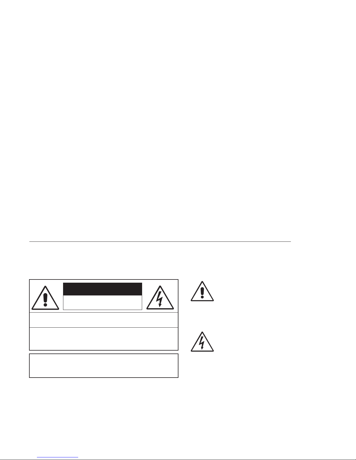
Hazard/Warning Label Identification
The Exclamation Point symbol,
CAUTION
RISK OF ELECTRIC SHOCK
DO NOT OPEN
WARNING: SHOCK HAZARD - DO NOT OPEN
AVIS: RISQUE DE CHOC ELECTRIQUE - NE PAS OUVRIR
CAUTION: TO REDUCE THE RISK OF ELECTRIC SHOCK DO NOT
REMOVE ANY COVER OR PANEL. NO USER SERVICEABLE PARTS
INSIDE. REFER SERVICING TO QUALIFIED SERVICE PERSONNEL.
WARNING: TO REDUCE THE RISK OF FIRE OR ELECTRIC SHOCK,
DO NOT EXPOSE THE POWER SUPPLY OR CONSOLE TO RAIN OR
MOISTURE.
WARNING—This equipment generates, uses, and can radiate radio frequency energy. If not installed and used in accordance with the instructions in this
manual it may cause interference to radio communications. It has been tested and found to comply with the limits for a Class A computing device
(pursuant to Subpart J of Part 15 FCC Rules), which are designed to pro vide reasonable protection against such interfer ence when oper ated in a commercial environment. Operation of this equipment in a residential area is likely to cause interference, in which case the user, at his own expense, will be
required to take whatever measures may be required to correct the interference.
iv
HARRIS CORPORATION
within an equilateral triangle, alerts the
user to the presence of important
operating and maintenance (servicing)
instructions in product literature and
instruction manuals.
The Lightning Flash With
Arrowhead symbol, within an
equilateral triangle, aler ts the user to
the presence of uninsulated
dangerous voltage within the
product’s enclosure that may be of
sufficient magnitude to constitute a
risk of electric shock.
Revision B • 1/03
Page 5

Manual Revisions
This page provides a quick reference of the
current document pages and their revision level. If
you receive a revision to this document from Harris,
replace the old manual pages with the new ones and
discard the old pages. Replace this page with the new
Manual Revisions page.
Revision Affected pages Comments
A All pages 2/02 First Release
B All pages 1/03 corrected various
installation & operation
descriptions. Added
accessory product
information.Condensed
manual page count.
v
HARRIS CORPORATION
Revision B • 1/03
Page 6

HARRIS CORPORATION
vi
Revision B • 1/03
Page 7

General
Information
Thank you for joining the growing ranks of
broadcasters employing Harris Corporation prod-
ucts designed by Pacific Research & Engineering.
Harris Corporation supplies audio products and sys-
tems to the world’s leading broadcast facilities. Our
mission is to provide the finest quality products,
systems, documentation, and after -sale support. We
invite comments and suggestions for improvements
to this documentation and to all of our services.
The Legacy is a very sophisticated console with
an extensive range of features contained in a compact design. To obtain maximum benefit from the
console’s capabilities, read the
Operation
PRODUCT OVERVIEW
Each Legacy console ships with the following
modules installed in the mainframe:
chapters prior to product installation.
• Microphone Preamplifier module (one
5-input Mic Preamp PCA standard, second
5-input Mic Preamp PCA optional)
• Universal Input modules (as ordered)
• Telco/Codec modules (up to 4, as ordered)
• Remote Line Selector (RLS) modules
(as ordered)
Installation
and
1
• Meter Switcher module (1 standard)
• Control Room module (1 standard)
• Studio module (1 optional)
• Output modules (2 standard)
Blank panels cover unused module positions.
The Legacy’ s motherboard and module area is
completely contained within a sheet metal and
extruded aluminum chassis for strength and RFI
immunity. The meter panel is hinged at the rear,
closing over the upper part of the modules to cover
the audio and logic connectors and the Logic Setup
switches. The chassis bottom is open beneath the
meter panel for easy cable access.
Module Descriptions
Microphone Preamplifier Module
This module (PRE99-1151-2) can hold ten
high-performance preamplifiers (five are standard
with an additional five optional). Each has a gain
trim control under a security cover. Phantom
power (+48 VDC) is selectable for each input. Each
Mic Preamp boosts its mic-level inputs (from -65
dBu to -30 dBu) to a line level (+4 dBu), low-impedance, balanced output for connection directly
to a Universal Input module or to outboard mic
processing equipment.
One module with a 5-input Mic Preamp PCA is
standard; a second optional 5-input PC A may be
installed. An additional 5-input Mic Preamplifier
module (PRE99-1151-2) or a 10-input Mic
Preamplifier module (PRE99-1151-1) may be installed into the slot directly to the right of the standard Mic Preamplifier module.
1-1
HARRIS CORPORATION
Revision B • 1/03
Page 8

1 General Information
Universal Analog/Digital Input Module
The Universal Input modules (PRE99-1315)
feature two inputs (A and B), each of which can
accept analog or digital signals. Setup switches on
the module set the source for each input. They
also set the source level (for analog signals) or the
attenuation amount (for digital signals). Each input has its own fully independent parallel logic
control connector for remote control of the module and/or module control of the associated source
equipment.
Each Universal Input module includes the following controls or features: A/B input selection,
channel on/off control, fader level control, cue
control, mode selection with pan/balance control,
Send control, and output bus selection to four program buses and one off-line bus.
Two 24-pin logic connectors connect logic wiring to/from external control panels or peripherals. DIP switches set logic and module function
options for the A and B inputs.
Telco/Codec Input Module
Up to four Telco/Codec (Telco) modules can be
installed into any of the input module slots on the
mainframe. The optional Telco module (PRE99-
1316) has a single audio input (analog or digital)
from a remote send and receive device (like a telephone hybrid, satellite transceiver , ISDN interface,
or other stereo or mono Codec).
Each module features manual or automatic control of the F oldback signal returned to the h ybrid
or codec. T he F oldback signal for each Telco module can be manually set to an y program or off-line
bus. T he F oldback signal can also follow the T elco
module’s on/off status when the Auto-Foldback
function is active. The Auto-Foldback function
automatically switches the feed to the caller between the off-line mix and the assigned bus with
the highest priority. For more information, see the
Telco Operation section on pages 3-7 to 3-9.
Each Telco module includes the following controls or features: channel on/off control, fader level
control, cue control, mode selection with pan/balance control, Send control, record and monitor
controls, and output/Foldback selection to four
program buses and one off-line bus. Logic I/O is
available for logic wiring to/from the hybrid or
codec.
Remote Line Selector (RLS) Module
This module (PRE99-1323) features two banks
of eight selection buttons to independently route
the eight input signals to the two outputs. The
module switch either analog or digital signals, as
set by a DIP switch on the module.
Meter Switcher Module
This module (PRE99-1317) is located to the
right of the input module area. It provides control
of the digital timer and contains the meter source
selector buttons and the signal drivers for all the
meter displays.
The timer control section features stop, start,
hold, and reset controls, as well as whether the
modules automatically reset the timer .
Control Room Module
This module (PRE99-1318) contains the monitor source selection and control facilities for the
console operator , and a co-host and a guest in the
control room. The module has parallel logic control (via a 14-pin connector) which provides external monitor dimming or muting, and warning
light control. The module includes four external
monitor inputs and six monitor and headphone
outputs. The outputs can simultaneously monitor
any combination of up to six analog sources (four
external inputs and Telco Record and Monitor)
and two digital sources (four programs and Send).
The Control Room module features monitor and
headphone fader -level controls, monitor -mode con-
HARRIS CORPORATION
1-2
Revision B • 1/03
Page 9

1 General Information
trol, cue and talkback level controls, and headphone Auto-Cue select.
Studio Module
The optional Studio module (PRE99-1319) is
installed to the right of the Control Room module.
It provides a monitor and talkback-level control
for one studio or voice booth. The monitor source
can be any combination of 11 sources (four exter nal inputs, four programs, Send, and T elco Record
and Monitor) simultaneously.
The Studio module has a 14-pin parallel logic
connector for external dimming or muting of the
studio monitor speakers and control of a studio
warning light interface. Controls also provide the
ability to talk to or from a studio and an external
location.
Output Modules
Two Output modules ship standard with the
Legacy.
The Output 1 module (PRE99-1320) contains
the digital-to-analog converters and mix matrices
for creating mix-minus foldbacks to support up
to four Telco/Codec modules. It also contains individually mixed outputs for Telco/Codec recording. There is a mix-minus output for each Telco/
Codec module. Digital and analog outputs are provided for the mix-minus and recorder feed outputs. For digital outputs, sample rates of 48 kHz
and 44.1 kHz are supported. T he mix-minus analog outputs are fixed at +4 dBu. This module features output sample rate selectors for digital outputs and a gain trim control for the analog Telco
record mix output.
The Output 2 module (PRE99-1321) contains
the AES digital output drivers, digital-to-analog
converters, and analog line amplifiers for the Send
output and the four program outputs. The digital
output sample rate is 48 kHz. An output sample
rate of 44.1 kHz can be selected for the program
1 and 2 auxiliary outputs, the program 3 and 4
outputs, and the Send output. Gain trim controls
for the analog outputs are also provided.
Pow er Supply
The separately packaged rack-mount power
supply assembly (PRE99-1202) uses keyed connectors to supply a single +48 volts DC to the console mainframe. There are two connectors from
the power supply assembly to the console: one connector supplies DC power and the other supplies
electrical signal information to the console. The
power supply module has an on/off switch and
an LED indicator on the front panel. The power
supply is fully regulated and protected against excessive current by internal fuses and electronic
safeguards.
1-3
HARRIS CORPORATION
Revision B • 1/03
Page 10

1 General Information
SPECIFICATIONS
The specifications for the Legacy are significantly more complete, and the related test conditions are more defined, than those usually shown
for consoles in this class. Be sure to follow the test
conditions and measure in the units as stated.
The specifications are for a fully loaded Legacy30 input mainframe.
Test Conditions:
Specifications are for the basic signal paths, per
channel, with >1k ohm loads connected to the
analog main outputs.
0 dBu corresponds to an amplitude of 0.775
volts RMS regardless of the circuit impedance. This
is equivalent to 0 dBm measured into a 600 ohm
circuit for convenient level measurement with
meters calibrated for 600 ohm circuits. Noise specifications are based upon a 22 kHz measurement
bandwidth. T he use of a meter with 30 kHz bandwidth will result in a noise measurement increase
of approximately 1.7 dB.
Total Harmonic Distortion (THD+N) is measured at a +18 dBu output level using 1 kHz or a
swept signal with a 22 kHz low-pass filter.
FSD = Full Scale Digital, +24 dBu
Microphone Preamplifiers
Source Impedance: 150 ohms
Input Impedance: 5 k ohms minimum, balanced
Input Level Range: Adjustable, -65 to -30 dBu
Input Headroom: >20 dB above nominal input
Output Level: +4 dBu, nominal
Analog Line Inputs
Input Impedance: >40 k ohms, balanced
Input Level Range: Selectable; -10 dBv, +4 dBu,
+6 dBu, +8 dBu
Input Headroom: 20 dB above nominal input
Analog Main Outputs
Output Source Impedance: <3 ohms balanced
Output Load Impedance: 1 k ohms minimum
Nominal Output Levels: Program, Send, Telco/Codec
Mix-Minus, T elco Record Mix F eed: +4 dBu, adjustable between +3 dBu and +9 dBu
Maximum Output Levels: Program, Send, Telco/
Codec Mix-Minus, Telco Record Mix Feed:
+24 dBu; +28 dBu with 100k output load impedance and nominal output level adjusted to
+8 dBu
Digital Inputs and Outputs
Reference Level: +4 dBu (-20 dB FSD)
Digital I/O: Through digital input and digital Pro-
gram, Send, Telco/Codec Mix-Minus outputs
Signal Format: AES-3, S/PDIF (input only)
AES-3 Input Compliance:
24-bit sample rate conver-
sion available, individually s witch selectable
AES-3 Output Compliance:
Digital Reference:
24-bit
Crystal (internal) or AES-3 (ex-
ternal) at 48 kHz ±100 ppm
Internal Sample Rate:
48 kHz
Output Sample Rates: Program 1 and 2 Main out-
puts 48 kHz; Program 1 and 2 Aux, Program 3
and 4, Send, T elco/Codec Mix-Minus, and Telco
Record Mix outputs 48 kHz or 44.1 kHz, individually switch selectable
Processing Resolution:
24-bit fixed with extended
precision accumulators
Conversions:
A/D 24-bit, Delta-Sigma, 128x
oversampling on all digital inputs; D/A 24-bit,
Delta-Sigma, 128x ov ersampling
Latency:
<1.6 ms, mic in to monitor out
HARRIS CORPORATION
1-4
Revision B • 1/03
Page 11

1 General Information
Monitor Outputs
Output Source Impedance: <3 ohms, balanced
Output Load Impedance: 1 k ohms minimum
Output Level: +4 dBu nominal, +24 dBu maximum
Frequency Response
Microphone or Line Input to Program or Send Output:
+0 dB/-0.5 dB, 20 Hz to 20 kHz
Dynamic Range
Analog Input to Analog Output: 105 dB referenced to
FSD, 108 dB “A” weighted to FSD
Analog Input to Digital Output: 109 dB referenced to
FSD
Digital Input to Analog Output: 107 dB referenced to
FSD, 110 dB “A” weighted to FSD
Digital Input to Digital Output: 138 dB
Equivalent Input Noise
Microphone Preamp: -127 dBu, 150 ohm source
Crosstalk Isolation
Program-to-Program or to-Program or to-Send: >95 dB,
20 Hz to 20 kHz
A Input to B Input, B Input to A Input:
>110 dB, 20 Hz
to 20 kHz
Stereo Separation
Analog Program Outputs: >86 dB, 20 Hz to 20 kHz
Console Power Requirements
Fully configured Legacy-14: 185 watts at 115/230
VAC, ±12%, 50/60 Hz
Fully configured Legacy-22: 250 watts at 115/230
VAC, ±12%, 50/60 Hz
Fully configured Legacy-30
:
285 watts at 115/230
VAC, ±12%, 50/60 Hz
Power Supply Voltage
Console power: +48 VDC at 8.34 Amp, redundant
operation optional
Total Harmonic Distortion + Noise
Mic Pre Input to Mic Pre Output: <0.005%, 20 Hz to
20 kHz, -38 dBu input, +18 dBu output, 100k
ohm load, 22 kHz filter bandwidth
Analog Input to Analog Output: <0.003% at 1 kHz,
+18 dBu input, +18 dBu output, 100 k ohm
load, 22 kHz filter bandwidth
Digital Input to Digital Output:
<0.00016%, 20 Hz to
20 kHz, -20 db FSD input, -20 db FSD output,
20 kHz filter bandwidth
Digital Input to Analog Output:
<0.003% at 1 kHz,
-6 db FSD input, +18 dBu output, 100 k ohm
load, 22 kHz filter bandwidth
Power Supply Ground
Rack-mount power supply frame: grounded through
AC cord
Power Supply Connection
AC input: IEC power cord
DC output: two keyed multi-pin connectors
Dimensions
Legacy-14: 9.75"
Legacy-22: 9.75
Legacy-30: 9.75
x 41.13" x 33.38" (H, W, D)
"
x 54.44" x 33.38" (H, W, D)
"
x 67.24" x 33.38" (H, W, D)
Power Supply (Rack-mount power supply frame):
3.5
"
(2 RU) x 19.0" x 16.0"
(H, W , D)
Harris Corporation reserves the right to change
specifications without notice or obligation.
1-5
HARRIS CORPORATION
Revision B • 1/03
Page 12

1 General Information
WARRANTY
The Legacy digital console carries a
manufacturer’s warranty which is subject to the
following guidelines and limitations:
A) Except as expressly excluded herein, Harris
Corporation (“Seller”) warrants equipment of
its own manufacture against faulty workmanship or the use of defective materials for a period of one (1) year from date of shipment to
Buyer . The liability of the Seller under this W arranty is limited to replacing, repairing, or issuing credit (at the Seller’s discretion) for any
equipment, provided that Seller is promptly
notified in writing within five (5) days upon
discovery of such defects by Buyer , and Seller’ s
examination of such equipment shall disclose
to its satisfaction that such defects existed at
the time shipment was originally made by
Seller, and Buyer returns the defective equipment to Seller’s place of business in Mason,
Ohio, packaging and transportation prepaid,
with return packaging and transport guaranteed.
E) This Warranty is void for equipment which
has been subject to abuse, improper installation, improper operation, improper or omitted maintenance, alteration, accident, negligence (in use, storage, transportation, or handling), operation not in accordance with
Seller’s operation and service instructions, or
operation outside of the environmental conditions specified by Seller.
F) This Warranty is the only warranty made by
Seller, and is in lieu of all other warranties,
including merchantability and fitness for a particular purpose, whether expressed or implied,
except as to title and to the expressed specifications contained in this manual. Seller ’ s sole
liability for any equipment failure or any
breach of this Warranty is as set forth in subparagraph A) above; Seller shall not be liable
or responsible for any business loss or interruption, or other consequential damages of an y
nature whatsoever, resulting from any equipment failure or breach of this warranty.
B) Equipment furnished by Seller, but manufac-
tured by another, shall be warranted only to
the extent provided by the other manufacturer .
C) Thermal filament devices, such as fuses, are
expressly excluded from this warranty.
D) The warranty period on equipment or parts
repaired or replaced under warranty shall expire upon the expiration date of the original
warranty .
HARRIS CORPORATION
1-6
Revision B • 1/03
Page 13
Installation
"
8
8
8
8
8
8
8
8
8
8
8
8
8
8
8
8
8
8
8
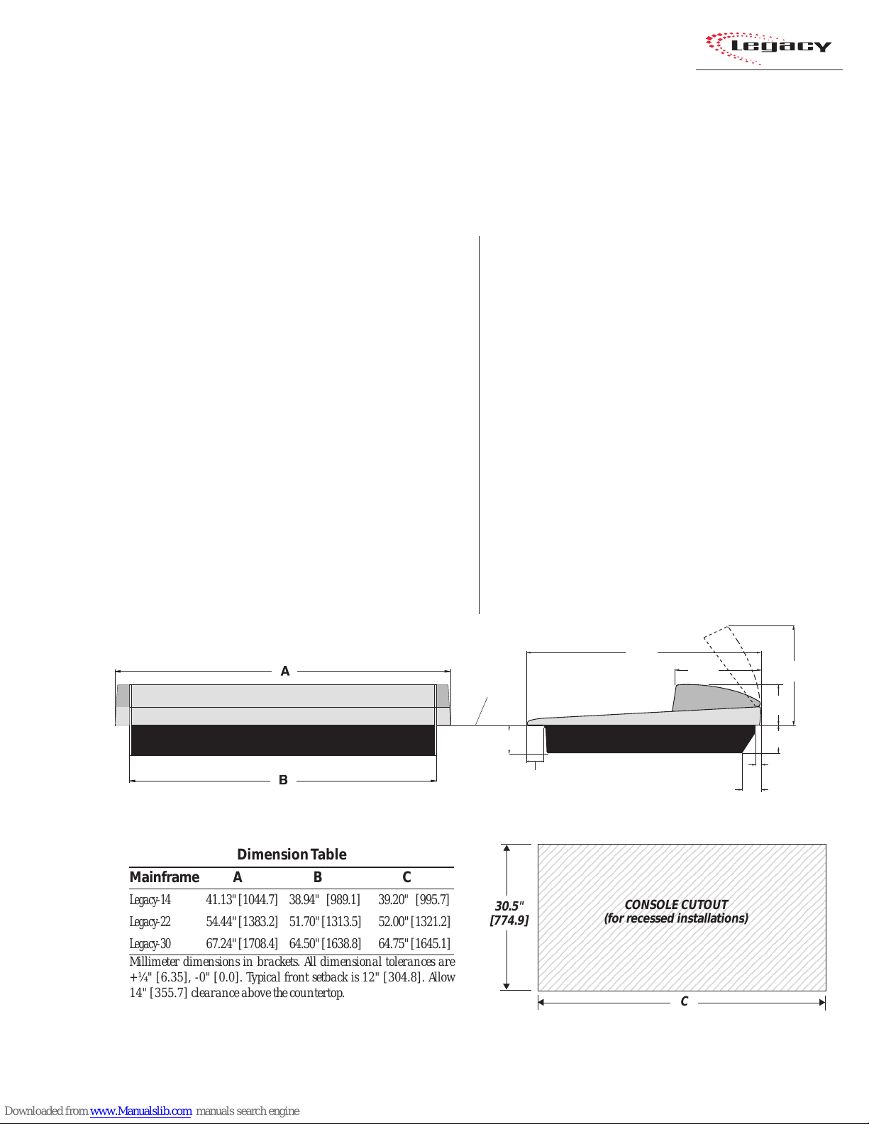
The Legacy mainframe is designed to
“drop into” a cutout (shown below) in the studio
furniture countertop. A minimum of 14 inches
(355.7 mm) of vertical clearance above the
countertop is required to fully open the meter
panel. T he rear 2.5 inches (63.5 mm) of the main-
2
The Legacy console shipment consists of:
• The 14-, 22-, or 30-input mainframe with the
standard modules (Microphone Preamp, Meter
Switcher , Control Room, and Outputs) installed,
along with the other modules ordered (Universal Input, T elco/Codec, RLS, Studio), and blank
panels to cover any unused positions.
• The rack-mount power supply assembly .
• T he Legacy Tool kit (3 AA batteries, AMP MOD
IV crimp tool and contact removal tool, hex
driver, and module removal tool).
frame is open so wiring can be easily dressed up
through the mainframe to the module connectors,
which are hidden below the meter panel.
Console Front View Console Side View, with dimensions (inches & [mm])
Dimension T able
Mainframe A B C
Legacy-14 41.13" [1044.7] 38.94" [989.1] 39.20" [995.7]
Legacy-22 54.44" [1383.2] 51.70" [1313.5] 52.00" [1321.2]
Legacy-30 67.24" [1708.4] 64.50" [1638.8] 64.75" [1645.1]
Millimeter dimensions in brackets. All dimensional tolerances are
+¼" [6.35], -0" [0.0]. Typical front setback is 12" [304.8]. Allow
14" [355.7] clearance above the countertop.
• Audio and Logic connector kit. The kit contains all the AMP MOD IV connector housings
and receptacle contacts typically needed for
installation.
COUNTERTOP
4.00"
[101.6]
2.48"
[63.0]
23456789012345678901234567890121234567
23456789012345678901234567890121234567
23456789012345678901234567890121234567
23456789012345678901234567890121234567
23456789012345678901234567890121234567
23456789012345678901234567890121234567
23456789012345678901234567890121234567
23456789012345678901234567890121234567
30.5"
[774.9]
23456789012345678901234567890121234567
23456789012345678901234567890121234567
23456789012345678901234567890121234567
23456789012345678901234567890121234567
23456789012345678901234567890121234567
23456789012345678901234567890121234567
23456789012345678901234567890121234567
23456789012345678901234567890121234567
23456789012345678901234567890121234567
23456789012345678901234567890121234567
23456789012345678901234567890121234567
2-1
HARRIS CORPORATION
Revision B • 1/03
33.38"
[847.9]
11.79"
[299.5]
CONSOLE CUTOUT
(for recessed installations)
C
5.75"
[146.1]
4.00"
[101.6]
0.75"
[19.1]
2.50"
[63.5]
14.00
[355.6]
Page 14
2 Installation
Console Installation
To simplify console installation, logic cable wir ing diagrams for specific peripheral equipment are
available from the Harris Technical Services department. See page 4-1 for contact information.
INSTALLATION NOTE: Do not locate the con-
sole near intense electromagnetic hum fields, such
as those produced by large power transformers
and by audio amplifiers that use inexpensive
power transformers operating in or near saturation. Strong electromagnetic fields may impair the
performance of the Legacy and neighboring equipment. Audio cables must also be routed to achieve
maximum practical distance from all AC power
mains wiring.
Legacy Mainframe, Module Configuration
MAINFRAME CONFIGURATION
The Legacy design positions the input modules
in the physical center of the mainframe. T his gives
the operator equal reach to peripheral equipment
located to the either side of the console.
Module Placement
The 14, 22, or 30 input module positions can
have any combination or order of the following
modules installed: Universal Input, Telco/Codec
(four maximum), and Remote Line Selector (RLS).
The remaining console positions are fixed. T he Mic
Preamplifier module(s), Meter Switcher module,
Control Room module, optional Studio module,
and the two Output modules must be positioned
as shown in the illustration below.
DSP Card 1 (Master) DSP Card 2 DSP Card 3* DSP Card 4*
Mic Preamp (standard)
Mic Preamp 2 (optional)
12.5” blank panel (standard)
Input modules
* (number of DSPs present
set by the frame size)
Output 1 (standard)
Output 2 (standard)
12.5” blank panel
The input module positions are
filled with any combination or
number of Universal Input and
Remote Line Selector modules, and
up to four Telco/Codec modules.
Control Room (standard)
Meter Switcher (standard)
Unused positions are covered with
25" Blank Panels.
Reserved position (covered by a 25" Blank panel)
Reserved position (covered by a 25" Blank panel)
12.25" Blank Panel (standard)
12.25" Blank Panel (standard)
NOTE:
The number of input module positions matches the console model number (e.g., Legacy-22 has 22 input positions). There are
two DSP cards in the Legacy-14, three in the Legacy-22, and four in the Legacy-30.
The areas covered by the five 12.25" Blank Panels can be used for mounting Harris BMXdigital Accessory Panels or custom remote
control panels. Since the Harris BMXdigital Accessory Panels are 6" long, a PRE99-1100 Divider Kit (for mounting up to four
Accessory Panels in place of two 12.25" Blank Panels), or a PRE99-1101 Divider Kit (for mounting up to six Accessory Panels in place
of three 12.25" Blank Panels) is required. Typically, the PRE99-1100 Divider Kit is installed in place of the Blank Panels on the left
end of the console and the PRE99-1101 is installed in place of the Blank Panels on the right end of the console. 6" Blank Panels
(PRE99-1714-3) cover unused Accessory Panel positions.
Studio (optional) 25” blank panel (standard)
12.25" Blank Panel (standard)
12.25" Blank Panel (standard)
12.25" Blank Panel (standard)
(standard)
HARRIS CORPORATION
2-2
Revision B • 1/03
Page 15
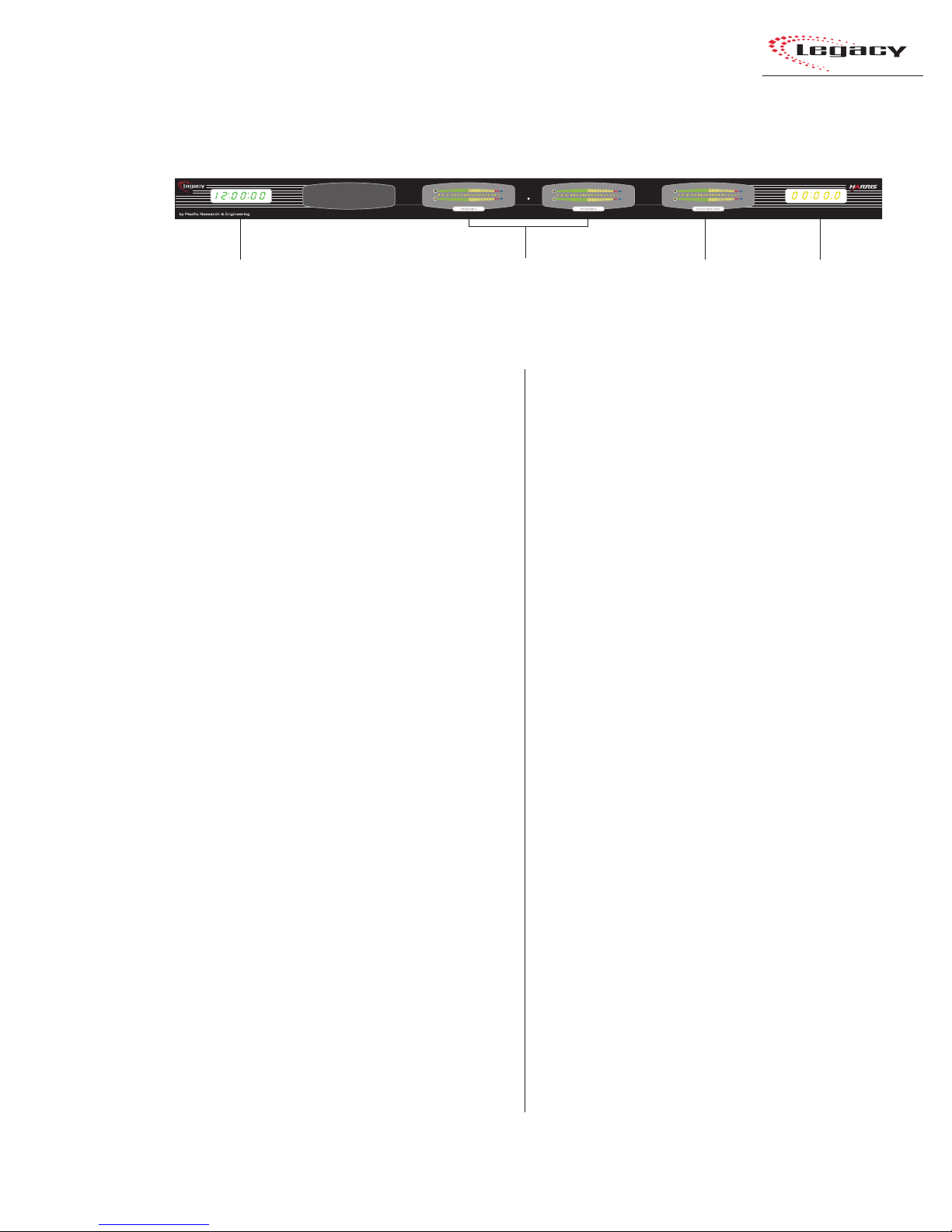
Legacy Meter Panel
2 Installation
Clock
Meter Panel
The meter panel contains three horizontal bargraph meters. T wo of the meters pro vide individual
level monitoring for the Program 1 and 2 outputs. The third meter is used to monitor the level
of Cue, Program 3 or 4, any external input, the
Send output, or the Telco Record output, as selected on the Meter Switcher module. The level at
which the peak indicator (PK) comes on, as well
as the meter display mode (peak hold or non-peak
hold), may be set for each meter via DIP s witches
on each meter display board.
The meter panel also contains a slaveable 12/
24-hour digital clock (HH:MM:SS) and an event
timer (MM:SS:T) that can be controlled manually , through buttons on the Meter Switcher module, or automatically through module On commands.
For additional information on the meter panel,
see pages 3-15 and 3-16.
Main Meters
(Program 1 and 2)
CONNECTOR AC CESS
meter panel in normal operation. T he meter panel
connects to the rear of the console by hinges. To
access the connectors, open the meter panel by
lifting it up and rotating it toward the rear of the
console until it stops.
the way so that it does not accidentally fall shut.
be removed from the mainframe chassis.
Aux M et e r
(Meter Switcher: Displays
Cue, Program 3 or 4, Send,
or Telco Record)
Event
Timer
All module connectors are hidden below the
Caution: Make sure that the panel is open all
To facilitate initial wiring, the meter panel can
To remove the meter panel from the mainframe:
1 Open the meter panel fully and unplug the
meter power cable (attached to the rear panel)
and the two cables (meter signals and talkback mic) from the Meter Switcher module.
2 With another person holding the meter panel,
remove the screws and bushings that attach
each gas spring to the meter panel. Lay the
gas springs on the mainframe while working.
3 Unlatch the hinges by moving the release pins
to their unlocked positions and lift the meter
panel up and off the mainframe.
To reinstall the meter panel, align the two halves
of the hinges, then release the pins out of their
unlocked positions.
Reattach each gas spring to the meter panel by
inserting a screw through the gas spring and the
bushing.
2-3
HARRIS CORPORATION
Revision B • 1/03
Page 16
2 Installation
POWER SUPPLY
The power supply assembly is rack mounted (it
requires 2 RU or 3.5" [88.9 mm] of rack space)
within the console cabinetry , below and to the left
or right of the supporting countertop. The Legacy
Power Supply must be installed so that the 30
foot power supply cable supplied with the Power
Supply is not under any tension when routed
through the cabinet and connected to the
mainframe’s rear panel connectors.
Connecting the Power Supply
The power supply cable has two connectors:
• A 5-pin connector to supply 48 volt DC
power to the console.
• A 4-pin connector to supply power supply
status information (Imminent Power Loss)
to the console.
Both connectors must be attached to the back
of the Legacy and to the power supply.
Power Connections —
Console Mainframe, Rear Panel
GROUNDING AND SHIELDING
The broadcast facility’s technical ground can
be connected to the mainframe chassis using the
threaded insert on the rear of the console (shown
in the Power Connections drawing on this page).
Use a 10-32 screw and crimp lug to terminate the
facility’s technical ground wire.
Connect the cable shields at both the console
and the peripheral end when all system components share a common ground potential and are
using isolated ground AC outlets tied individually
back to the main technical ground.
If isolated ground AC outlets are not available,
connect the cable shields at the console end only.
The shields should be floated (left unconnected)
at the peripheral device end. Ensure the peripheral devices connect to a clean ground through
their power cords, or through separate ground
wires to the facility’s technical ground.
POWER SUPPLY GROUNDING
NOTE: The Power Supply chassis
connects to the AC mains safety or
“U” ground wire.
Meter
Panel
Power
48 VDC
Power
Power
Supply
Status
DC GROUNDING NOTE:
connect
the audio or logic supply
ground wiring to the chassis of the
power supply .
AC GROUNDING NOTE: Do not
defeat the safety ground in any way.
Doing so may provide a potentially
dangerous condition to the operator .
HARRIS CORPORATION
Threaded
Insert for
10-32
screw
Do not
AUDIO GROUND NOISES: Buzz pickup is gener-
ally electrostatic—such as capacitive coupling
between an audio line and a power line. To avoid
audio ground noises, do not route audio lines in
the same wireway as an AC power line.
INST ALLING BA CKUP BATTERIES
Three AA rechargeable NiCad batteries are supplied in the 76-2001 Tool Kit. They supply a “Keep
Alive” voltage to hold each module’s logic state
during momentary power outages. They mount in
a battery clip located below the three 12" blank
panels on the right end of the console.
To install the backup batteries:
1 Remove the three blank panels located in front
of the Output modules.
2-4
Revision B • 1/03
Page 17
2 Installation
3
3
3
3
3
3
3
3
3
3
3
3
3
3
3
3
3
3
3
3
3
3
3
3
3
3
3
3
3
3
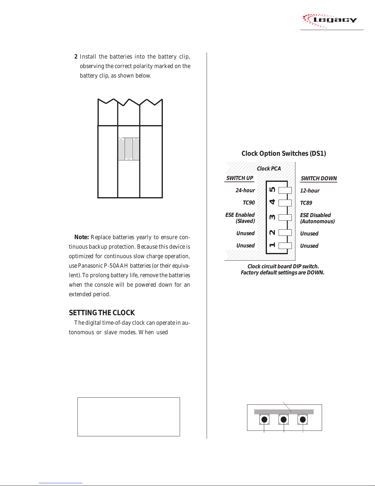
2 Install the batteries into the battery clip,
observing the correct polarity marked on the
battery clip, as shown below.
Backup Battery Installation
Output 1
+- +
-+-
12.25" Blank panel
Middle 12.25" Blank Panel
removed to show the
battery clip
Note: Replace batteries yearly to ensure con-
tinuous backup protection. Because this device is
optimized for continuous slow charge operation,
use Panasonic P-50AAH batteries (or their equiv alent). To prolong battery life, remo ve the batteries
when the console will be powered down for an
extended period.
SETTING THE CL OCK
The digital time-of-day clock can operate in autonomous or slave modes. When used autonomously (the factory preset), a temperature-controlled quartz crystal oscillator controls the clock
timing. In slav e mode, clock timing comes from a
TC89- or TC90-compatible ESE master clock reference signal.
Master clocks are available from:
ESE
142 Sierra St.
El Segundo, CA 90245.
Telephone: 310.322.2136
www.ese-web.com
Output 2
the type of ESE signal (TC89 or TC90), and the
type of clock time desired (12-hour or 24-hour
format) are set using DIP switch DS1 on the clock
PCA. DS1 is on the right rear edge of the circuit
board.
Blank
The clock PCA is mounted behind the clock display on the meter panel.
234567890123456789012
234567890123456789012
234567890123456789012
234567890123456789012
234567890123456789012
12.25" Blank panel
234567890123456789012
SWITCH UP
234567890123456789012
234567890123456789012
234567890123456789012
234567890123456789012
234567890123456789012
234567890123456789012
234567890123456789012
234567890123456789012
234567890123456789012
234567890123456789012
234567890123456789012
ESE Enabled
234567890123456789012
234567890123456789012
234567890123456789012
234567890123456789012
234567890123456789012
234567890123456789012
234567890123456789012
234567890123456789012
234567890123456789012
234567890123456789012
234567890123456789012
234567890123456789012
234567890123456789012
be set after power-up. There are three clock set
buttons on the bottom left front of the clock PCA.
2-5
HARRIS CORPORATION
Revision B • 1/03
The operating mode (autonomous or ESE slav e),
To access the clock PCA, open the meter panel.
Clock Option Switches (DS1)
Clock PCA
SWITCH DOWN
24-hour
TC90
12-hour
TC89
ESE Disabled
(Slaved)
Unused
Unused
12 3 45
(Autonomous)
Unused
Unused
Clock circuit board DIP switch.
Factory default settings are DOWN.
With the clock set to autonomous mode, it must
• Use the right button (F ast) to scroll by minutes at a time.
• Use the middle button (Slow) to scroll by
seconds at a time.
• Use the left button (Hold) to synchronize
the console clock to an external time reference by setting the clock ahead of the
Setting the Clock
Clock Circuit Board, left front edge
Hold Slow Fast
Page 18
2 Installation
6
6
6
6
6
6
6
6
6
6
6
6
6
6
6
6
6
6
6
6
6
6
6
6
6
6
6
6
6
6
1234567890123456789012345678901212345678901234567
1234567890123456789012345678901212345678901234567
external time reference, then press and hold
the HOLD button to freeze the time. When
the external time reference reaches the time
on the Legacy clock, release the HOLD button to start the clock.
When an ESE time-code signal is connected to
the BNC connector on the clock circuit board, and
slave mode is selected (DS1-3 is set UP), the clock
does not require setting. If the ESE time-code signal fails, the clock automatically defaults to its
internal crystal reference oscillator, flashing the
display colons to indicate the loss of time-code.
EVENT TIMER
The event timer displays time in minutes, seconds and tenths of seconds. T he only timer option
setting is whether to display the tenths of seconds
digit as the timer runs. DS1-1 (a DIP switch on
the timer circuit board, located behind the timer
display), sets whether the tenths are shown or not.
In the UP position, the tenths of seconds are displayed. In the DO WN position, the factory default,
the tenths do not display while the timer runs.
Note that the tenths of seconds are always shown
when the timer is in the Stop or Hold mode.
Event Timer Option Switches (DS1)
234567890123456789012345
234567890123456789012345
234567890123456789012345
234567890123456789012345
234567890123456789012345
234567890123456789012345
SWITCH UP
234567890123456789012345
234567890123456789012345
234567890123456789012345
234567890123456789012345
234567890123456789012345
234567890123456789012345
234567890123456789012345
234567890123456789012345
234567890123456789012345
234567890123456789012345
234567890123456789012345
234567890123456789012345
234567890123456789012345
234567890123456789012345
234567890123456789012345
234567890123456789012345
234567890123456789012345
234567890123456789012345
234567890123456789012345
234567890123456789012345
.1 sec display ON
234567890123456789012345
234567890123456789012345
234567890123456789012345
234567890123456789012345
Unused
Unused
Unused
Unused
Timer PCA
12345
SWITCH DOWN
Unused
Unused
Unused
Unused
.1 sec display OFF
Timer circuit board DIP switch.
Factory default settings are DOWN.
METER SETUP
The level at which the blue peak indicators turn
on, as well as the meter display mode (peak hold
or non-peak hold), is set separately for each meter
using DIP switches on the edge of each meter PCA.
To access the meter DIP switches, open the meter
panel by lifting it up and rotating it toward the
rear of the console until it stops. Each meter ’s DIP
switches are located on the underside of the meter
panel, directly below the right end of each meter.
Meter DIP Switch Definitions
# Switch Name UP Function (switch set up) DOWN Function (switch set down)
1 Peak Indicator Level See Switch 1 and 2 Table, below
2 Peak Indicator Level See Switch 1 and 2 Table, below
3 Meter Display Mode Non-peak hold Peak hold
4 Spare Switch
5 Termination Switch Set UP for Meter 1 (PGM 1) Set DOWN for Meters 2 & 3
Switch 1 and 2 Table
Use these switches to set the level
where the Blue peak indicators light.
#1 # 2 Peak Level
DOWN DOWN 0dB
UP DOWN -2dB
DOWN UP -4dB
UP UP -6dB
Meter Option Switches (DSW2)
Switches 1, 2, 3 shown down,
switches 4 and 5 shown up.
2-6
HARRIS CORPORATION
Revision B • 1/03
123 45
Meter PCA
Page 19
2 Installation
Cabling and Wiring
Before installing the console, draw up a facility
wiring plan that lists the console interconnections
with all peripheral devices. Identify and create tags
for all audio and logic cabling. List each connection in a master facility wiring logbook to facilitate wiring installation, future system wiring
changes, equipment updates, and system troubleshooting.
Refer to the module Quick Connection Guides,
on pages 2-16 to 2-49, for information on each
audio and logic connection (including block diagrams for each logic interface connector) and on
each module’s setup DIP switches.
REQUIRED CABLES AND WIRE
The Legacy uses the following types of cables
and wires:
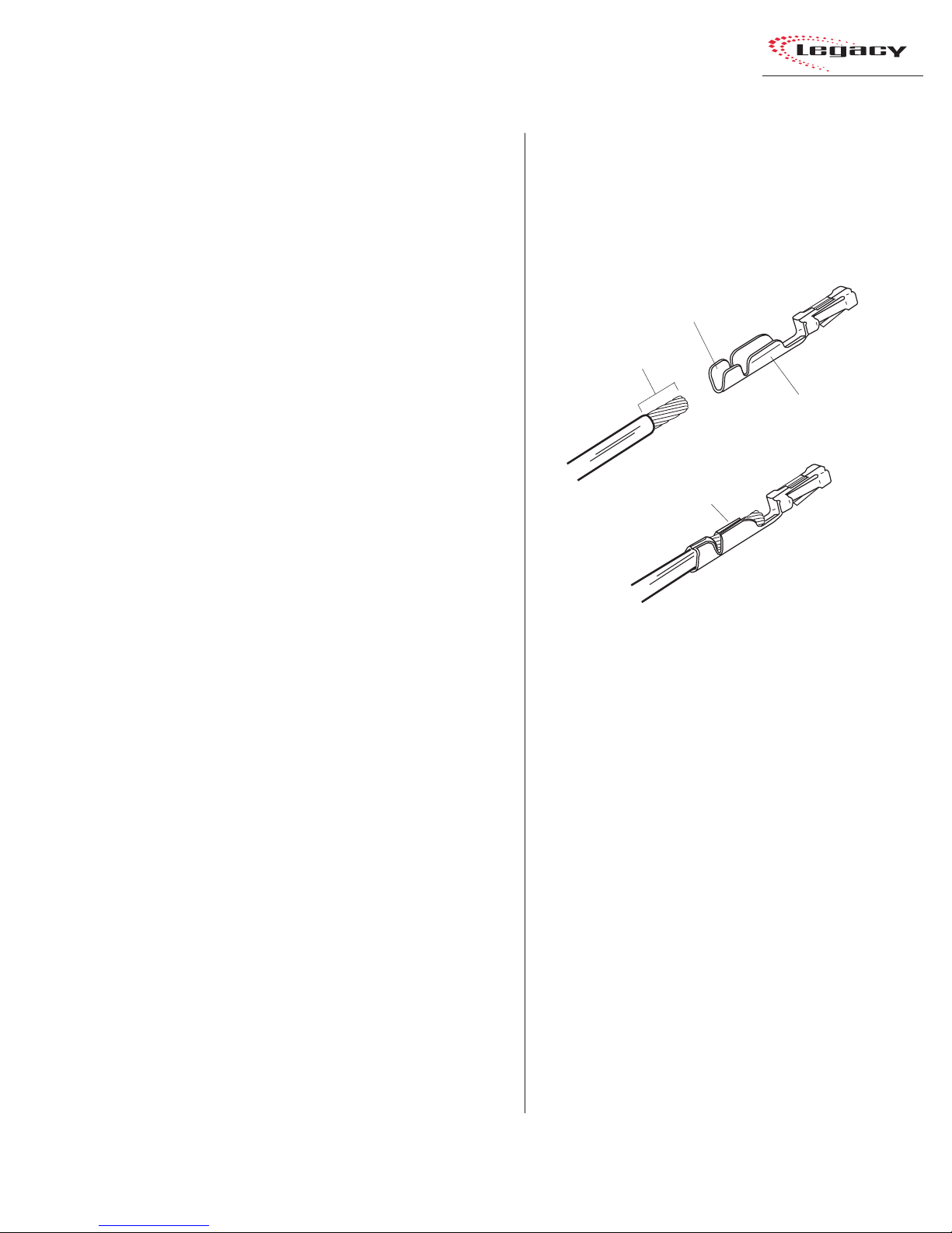
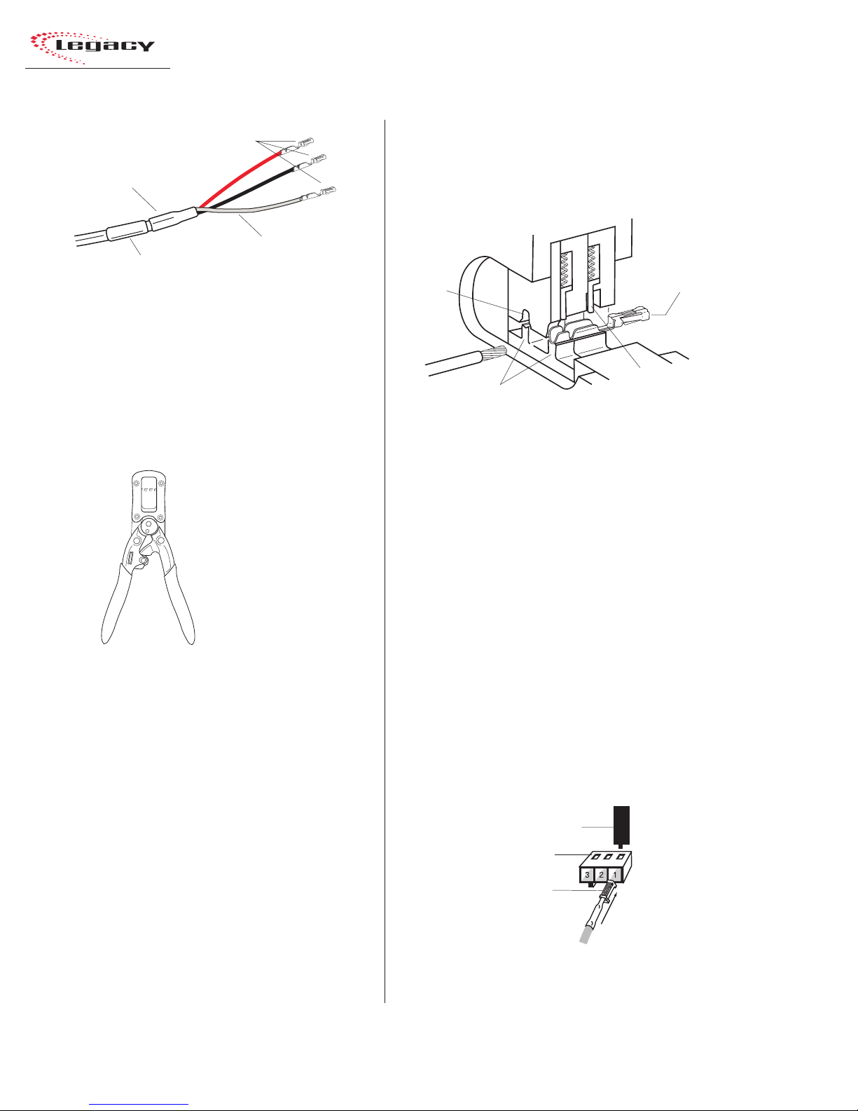
WIRE PREPARATION
All Legacy audio and logic wiring terminates
in AMP MOD IV receptacle contacts at the console. Stranded wire of 22 to 26 A WG, with insulation diameters of .040 to .060 inch, can be used
with the AMP MOD IV receptacle contacts.
Insulation Barrel
9/64” [3.57 mm]
Wire Barrel
Properly
Crimped Contact
• Analog audio connections require twoconductor, stranded, insulated, foil-shield
cable using a separate shield drain wire
(equivalent to Belden 8451, 9451 or 8761).
• AES/EBU connections require 110 ohm
two-conductor, stranded, insulated, foilshield cable containing a separate shield
drain wire (equivalent to Belden 1800A).
• Logic control cables require stranded, 22
AWG, multiple-conductor, non-shielded,
jacketed cable (equivalent to Belden 9423,
8457 or 9421). The number of conductors
used is determined by the application. Typically cables with five and eight wires are
most often used for constructing logic
cables. Even though there are eighteen distinct signals on the Logic Interface connector, only a handful are typically used for
any given application.
AMP MOD IV Receptacle Contacts
Follow these steps for audio wire preparation:
1 Strip the cable insulation jacket and foil shield
back 1½" [38.10 mm].
2 Remove the foil shield and sleeve the drain
wire with 20 AWG Teflon sleeving. Leave
9/64" [3.57 mm] of the drain wire exposed.
3 Cover the cut end of the jacket with 3/4"
[19.05 mm] of heat-shrink tubing. Shrink this
tubing, centered on the jacket cut end, to hold
the drain wire sleeving in place.
4 Strip the signal wire insulation back 9/64"
[3.57 mm].
5 Crimp the receptacle contact onto the wire
and insulation.
Audio Cable Shield Note: To ensure your in-
stallation follows recommended grounding procedures, you must sleeve all drain wires with Teflon sleeving and put heat shrink tubing over all
cable jacket cut ends to insulate the shield wire.
2-7
HARRIS CORPORATION
Revision B • 1/03
Page 20
2 Installation
AMP MOD IV
Receptacle Contacts
3/4” [19.05 mm]
Shrink T ubing
Te flon Sleeving
Cable ID
Tag
over drai n wire
Audio Wire , ready for insertion into an
AMP MOD IV connector housing
Logic control cables are fabricated in a similar
manner to the audio wiring. Strip the jacket insulation back 1½" [38.10 mm], sleeve the cut end
with 3/4" [19.05 mm] of shrink tubing and strip
the insulation from each wire 9/64" [3.57 mm].
AMP MOD IV
Contact
Crimp Tool
CRIMP TOOL OPERATION
A ratcheting AMP MOD IV crimp tool is
included in the tool kit. The tool crimps both the
insulation and wire barrels on the AMP MOD IV
receptacle contacts in one crimping action.
To use the ratcheting crimp tool:
1 Hold the crimp tool with the printed side up.
Insert the contact from the opposite side, with
the barrel openings up, until the insulation
barrel end is flush to the opening of the die.
Close the tool only until the anvil holds the
contact in place (Refer to the cutaway view
on this page).
2 Insert the stripped wire into the contact until
it hits the tool’s wire stop. Hold the wire in
place while squeezing the tool handles to
crimp the contact onto the wire. The tool
handles automatically release and spring open
after the crimp cycle is complete.
Printed
Side
Die
Anvils
AMP MOD IV
Receptacle
Contact
Wire Stop
Crimp Tool — Cutaway View
Once the contact has been crimped, insert and
lock the contact receptacle into the appropriate
connector housing following the pin-out diagrams
found in the Quick Guides on pages 2-16 to 2-49.
A receptacle contact is inserted into the housing with its locking tab side toward the locking
tab slots on the side of the connector housing. A
slight click can be heard when the contact’s locking tab springs up into the locking tab slot.
To remove a contact from a housing, the PRE70129 Contact Removal Tool (included in the PRE
76-2001 tool kit) is required. Insert the tool’s tip
into the locking tab slot and press the locking tab
down while lightly pulling on the wire to remove
the contact from the housing.
Contact Removal Tool
Locking Tab Slots
Locking Tab
Receptacle Contact
Insertion & Removal Detail
HARRIS CORPORATION
2-8
Revision B • 1/03
Page 21
2 Installation
AUDIO CONNECTIONS
Audio connections take advantage of the threepins per row design of the three- and six-pin AMP
MOD IV housings. Three-pin housings are used
for balanced digital connections while six-pin
housings are used for balanced analog connections.
One important exception is the Mic Preamp module, which uses three-pin connectors for balanced
analog microphone inputs.
Pin Numbers for Analog &
Digital Audio Connectors
3
2
1
3-pin
connector
Pin numbering always shown from the wire insertion
end, oriented from the board operator’s perspective.
All audio wiring, when plugged into a module
connector , has this orientation:
• T he audio shields are on pins 1 and 4 (the
pins closest to the board operator).
• The audio low wires (typically the black
wires) are on pins 2 and 5 (the middle pins).
• The audio high wires (typically the red
wires) are on pins 3 and 6 (the back pins).
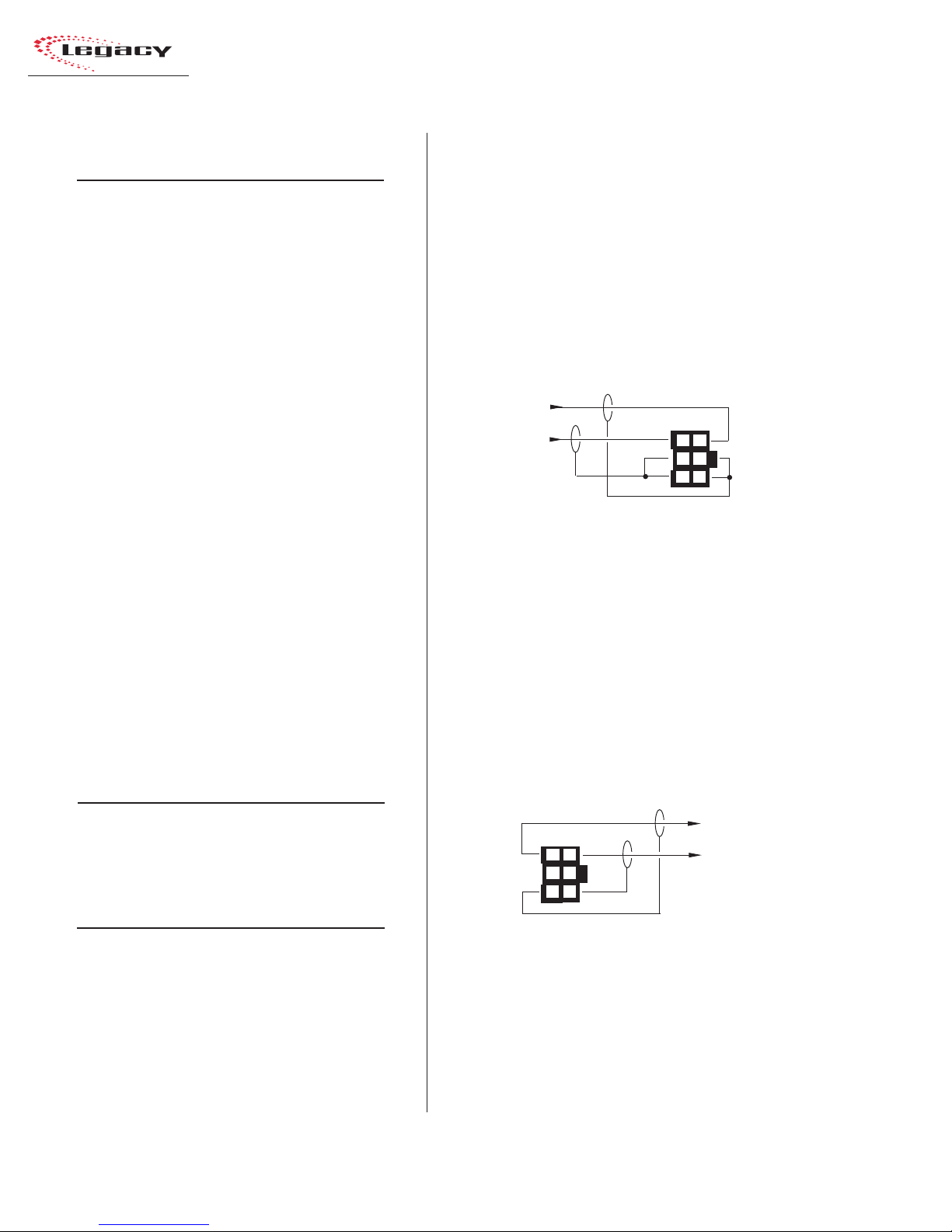
For stereo applications, the left channel wires
plug into the left column of pins and the right channel wires plug into the right column of pins (from
the board operator’s perspective).
When a six-pin input comes from a mono source
(such as an external microphone preamp output),
the left and right inputs should be paralleled together (pins 1 and 4 tied together, pins 2 and 5
tied together and pins 3 and 6 tied together). If
this is not done, then the module’s mode buttons
will have to be set for mono operation (see page
3-4 for L/R Mode information on the Universal
Input Module).
6
3
5
2
4
1
6-pin
connector
Analog Connections
There are no analog interstage patch points
within the Legacy input or output modules. To
use the console with a patch bay, connect the line
level outputs from the peripheral devices directly
to the patch bay. Normal these signals to the appropriate analog input modules.
Likewise, the Legacy’s analog outputs may be
routed through a patch bay normalled to standard peripherals such as analog on-air processing gear, recorders, telephone hybrids, etc.
The Mic Preamp module’ s line-level outputs (+4
dBu, nominal, balanced, mono outputs) can also
be routed through a patch bay normalled to an
input module, or to external mic processing.
When a mic processor with only a microphone
level input is used, the microphone is connected
directly to the mic processor, with the processor’s
line-level output either directly connected to an
input module (using the mono wiring pinout
shown below) or through a patch bay normalled
to an input module.
Two-Channel (Stereo)
Line Input or Output — 6-Pin Housing
Pin Signal Description
1 Shield for the left channel, or signal 1
2 Low (- input or output), left channel, or signal 1
3 High (+ input or output), left channel, or signal 1
4 Shield for the right channel, or signal 2
5 Low (- input or output), right channel, or signal 2
6 High (+ input or output), right channel, or signal 2
Single Channel (Mono)
Line Input — 6-Pin Connector
Pin Signal Description
1 Shield (connects directly to the chassis)
2 Low (- input) tied to pin 5
3 High (+ input) tied to pin 6
4 Shield (connects directly to the chassis)
5 Low (- input) from pin 2
6 High (+ input) from pin 3
2-9
HARRIS CORPORATION
Revision B • 1/03
Page 22
2 Installation
Microphone Input — 3-Pin Connector
Pin Signal Description
1 Shield (connects directly to the chassis)
2 Low (- input)
3 High (+ input)
Digital Connections
Most of Legacy’s digital inputs and outputs are
wired like the Microphone Input shown above. One
exception is the RLS module, which uses 6-pin
connectors since it can be set for analog or digital
operation. When set for digital, the signals connect using pins 1, 2, and 3 of the connector.
The other modules with digital inputs or outputs; Universal Input, Telco/Codec, Output 1 and
2, use three-pin connectors like that shown abo ve.
The digital inputs accept AES-3 (AES/EBU) compatible signals and, as mentioned in the Unbalanced Connections section that follows, can also
accept S/PDIF signals in most cases.
Each digital output is an AES-3 compatible signal (nominal sample rate is 48 kHz, but some
outputs are switch selectable for 44.1 kHz) . AES3 output signals cannot connect directly to an
S/PDIF input. A signal translation interface is required to accomplish this function.
AES/EBU Digital Inputs and
External Clock Reference Input
Pin Signal Description
1 Shield (connects directly to the chassis)
2 Low (- input)
3 High (+ input)
AES/EBU Digital Outputs
Pin Signal Description
1 Shield for AES/EBU signal
2 Low (- output)
3 High (+ output)
UNBALANCED CONNECTIONS
Although all analog inputs and outputs are
active and balanced, unbalanced consumer or
“semipro” equipment can be connected to the con-
sole. For best results, connect an unbalanced device through an IHF-PRO match box and keep
the unbalanced cable lengths as short as possible.
If a match box is not available, connect an unbalanced device to a Legacy input using the following illustration.
Connecting an Unbalanced Device
to a Legacy Analog Input
From the
Unbalanced
Device
R
L
Shields
Console
Balanced
Input
3
6
2
5
1
4
When an unbalanced device must connect to a
Legacy balanced analog output, and an IHF-PRO
match box is not available, do not tie the low (-)
and shield pins together to “unbalance” the signal. The low output pin must always be left “floating” when unbalancing a Legacy output, as shown
in the following illustration.
Connecting an Unbalanced Device
to a Legacy Analog Output
(Nominal Output is -2 dBu)
Console
Balanced
Output
3
6
2
5
1
4
(Make no connections to pins 2 & 5)
To the
Unbalanced
Device
L
R
Shields
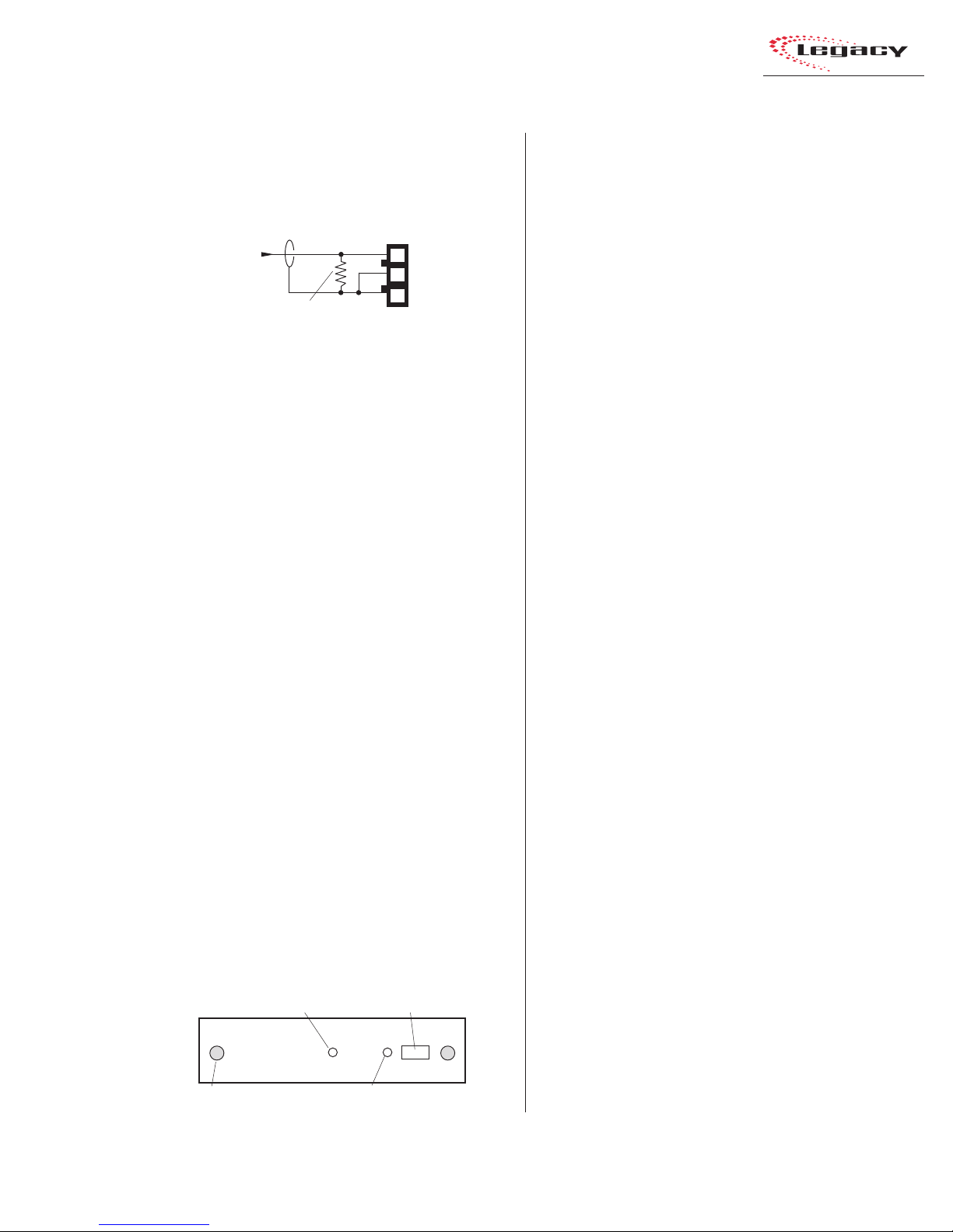
S/PDIF Signals
Digital devices with only an S/PDIF digital output can connect to a Legacy input, but only when
a 249 ohm resistor is added to load the 75 ohm
S/PDIF cable. Install the resistor at the AMP MOD
IV housing per the illustration on the next page.
HARRIS CORPORATION
2-10
Revision B • 1/03
Page 23
2 Installation
Connecting an S/PDIF Device to
a Legacy AES/EBU Input
From
S/PDIF
Device
Signal
Shield
249 ohm resistor
Console
AES/EBU
Input
3
2
1
An unbalanced-to-balanced line transformer
can also be used to interface an S/PDIF signal.
Note 1: A signal conversion interface must be
used to connect an AES/EBU output to a S/PDIF
input.
Note 2: Some S/PDIF signals may not work with
the Legacy’s inputs, even with the additional load
resistor or a transformer , because of nonstandard
levels or protocols in the S/PDIF product.
DIGITAL CLOCK REFERENCE
The Legacy has an internal clock for sample
rate timing, with sample rate converters on each
input to synchronize/convert external digital signals to the console’s internal 48 kHz sample rate.
The console can automatically synchronize to an
external AES-3 digital reference signal (of 48 kHz,
±100 ppm only) through a 3-pin connector on the
left DSP card (the DSP cards are along the back
of the mainframe, below the meter panel).
A green LED next to the connector indicates
whether the console is using internal reference
(LED is lit), or using the external reference (LED
is off). If an external reference signal is connected,
and yet the LED is still lit, this indicates the refer ence signal is not present or is out of range.
Master DSP Card
LED — When lit, indicates
the card is operating
Thumb
screw (x2)
LED — When lit, indicates the console
is using an internal reference
3-pin digital connector
(Master DSP card only)
LOGIC CONNECTIONS
Legacy modules have built-in logic I/O interfaces that can control, or be controlled by,
peripheral devices connected to the console. For
example, a CD pla yer connected to a module can
be automatically started when the module is
turned on. Then, at the end of the cut, the CD
Player logic can turn the module audio off and
control the off button illumination to indicate that
the cut has been played.
When a mic remote control panel is connected,
its On, Off, Cough, and Talkback buttons control
the module while tally outputs from the module
control the button tallies on the mic panel.
Legacy modules have the following logic connectors:
• Universal Input modules have two LOGIC
I/O connectors for controlling the devices
connected to the A and B inputs.
• Telco modules have a single LOGIC I/O
connector for controlling the device connected to the module.
• T he Meter Switcher module has three EXT
TIMER connectors for resetting studio or
producer timers, and the connectors for the
factory-installed wiring that ties the mainframe to the meter panel.
• The Control Room module has a LOGIC
connector for the warning light and talkback outputs and the remote mute and dim
inputs. A CUE CNTL connector allows external cue input control.
• T he optional Studio module has one LOGIC
connector for the studio warning light and
talkback outputs and the remote mute and
dim inputs and tally outputs. An EXTERNAL connector has the talkback commands and the audio (both to and from)
for an external location.
2-11
HARRIS CORPORATION
Revision B • 1/03
Page 24

2 Installation
MODULE QUICK GUIDES
Pages 2-16 to 2-49 have Quick Guides to configuring each module’s logic connections and DIP
switch settings. Each guide includes the audio and
logic connector pinouts and signal descriptions,
DIP switch setting definitions and, for some modules, logic block diagrams.
Module Quick Guides:
• Mic Preamp: pages 2-16 & 2-17
• Universal Input: pages 2-18 to 2-21
• Telco/Codec: pages 2-22 to 2-25
• RLS: pages 2-26 & 2-27
• Meter Switcher: pages 2-28 to 2-30
• Control Room: pages 2-32 to 2-37
• Studio: pages 2-38 to 2-45
• Output 1: pages 2-46 & 2-47
• Output 2: pages 2-48 & 2-49
Pages 2-50 to 2-55 show examples of typical
logic connections to the Universal Input module
for a mic remote control panel, a CD player, and a
digital delivery system.
Note: To completely isolate the console from the
peripheral device, use only the opto-isolated control input and output connections since the Logic
Ground and Logic Supply +5VDC connections are
referenced to the console’s logic power supply and
ground.
Connect these only to isolated devices, such as
a mic control panel or other Harris Accessory
Panel. Connecting the logic ground to a nonisolated peripheral device can result in a ground
loop between the console and the peripheral
device.
UNIVERSAL INPUT LOGIC INTERF A C E
A block diagram of the Universal Input module
logic interface is shown on page 2-13. Logic outputs (shown on the right side of the illustration)
are isolated from the peripheral device by six solidstate “relays . ” T he “relay contacts” can switch logic
voltages up to 60 volts at 350 mA.
Pressing the On button generates a 220 ms contact closure from pin 5 (Start Command Pulse). A
sustained contact closure while On is available on
pin 23 (Start Command Sustained). It stays closed
as long as the module is On. Pressing the Off button generates a 220 ms closure from pin 4 (Stop
Command Pulse). These three command outputs
are tied together at pin 13 (Command Common).
Module DIP switches DS2-2 (for the A input)
and DS4-2 (for the B input), set whether a single
pulse is output when the module status changes
(Off to On, or On to Off), or if each additional
press of the On or Off buttons produces another
contact closure. The default setting (switch 2 set
to OFF) is a single contact closure. When DS2-2
or DS4-2 is set to On, then each additional press
of the On or Off button produces another 220 ms
contact closure.
T he remaining outputs; Logic Activ e/Cue Tally
[pin 15], On Tally [pin 17], and Off Tally [pin 16],
are tied together at Tally Common [pin 14]. They
present sustained logic outputs for each function.
There are six logic inputs on the left side of the
illustration: Reset/Talk to Studio, Ready/Talk to
External, On, Off, Cough, and Talk to Control
Room/Ext. Cue. T hese inputs are opto-isolated and
current limited so any logic voltage from +5 to
+40 VDC can be used.
Reset/Talk to Studio, and Ready/Talk to External have both high (+) and low (-) input pins so
that either polarity logic can be used. The other
inputs use active low logic (pull to ground) that
typically come from a mic control panel (although
On and Off could be triggered by a peripheral
HARRIS CORPORATION
2-12
Revision B • 1/03
Page 25
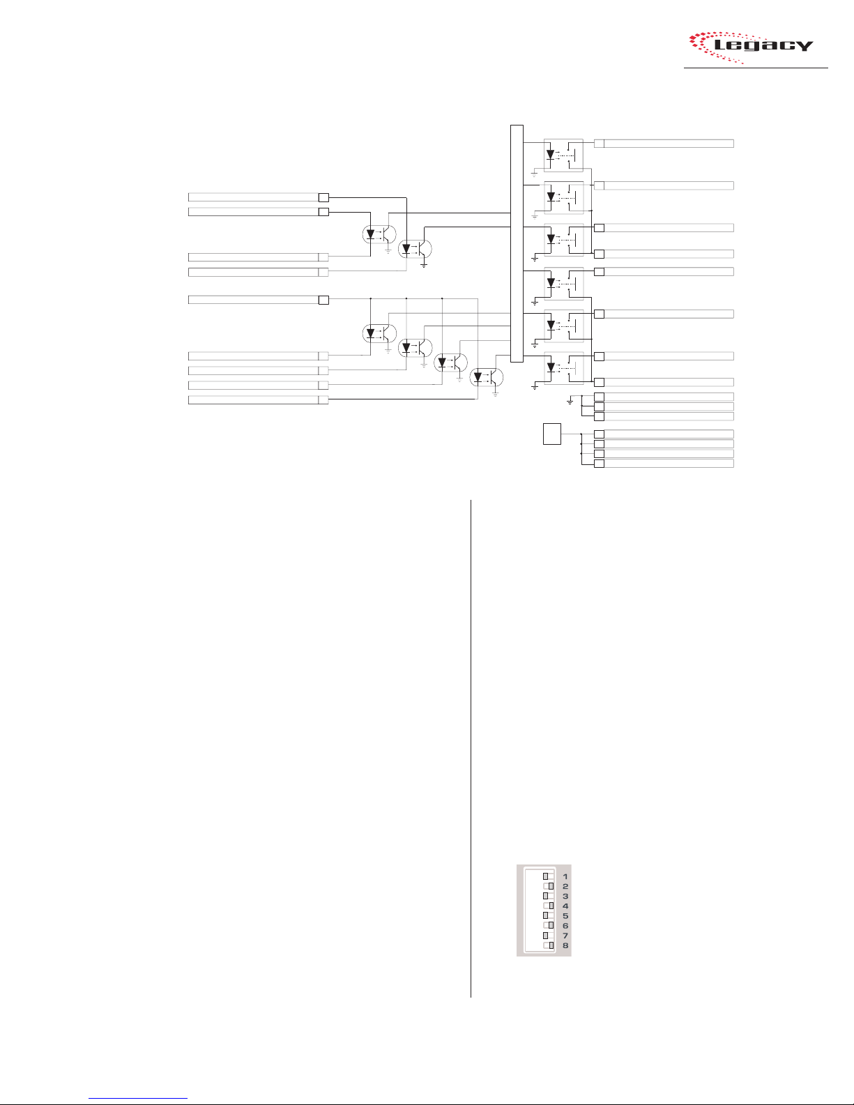
Block Diagram, Universal Input
Module Logic Interface
MIC: Talk to Studio (+) LINE: Reset Input (+)
MIC: Talk to Ext. (+) LINE: Ready Input (+)
MIC: Talk to Ext. (-) LINE: Ready Input (-)
MIC: Talk to Studio (-) LINE: Reset Input (-)
22
24
21
19
2 Installation
Start Command Pulse
5
Stop Command Pulse
4
Start Command Sustained
23
Command Commo n
Internal Logic
13
MIC: Logic Active Tally LINE: Cue Tally
15
Activate Logic Inputs(+)
On Input (-)
Off Input (-)
Cough Input (-)
MIC: Talk To C/R (-) LINE: Cue Input (-)
Notes:
Opto-Isolator inputs can handle +5 to +40 VDC logic
Opto-Isolator outputs can handle up to 60 volts or 350 mA
18
7
8
9
20
device). T o use these inputs, pin 18 (Activate Logic
Inputs) must be jumpered to the + logic voltage.
Typically this is pin 6 (Logic Supply +5 VDC), but
it can also be supplied by the peripheral device.
The Reset/Talk to Studio and Ready/Talk to
External inputs can use either active low logic (pull
to ground) or active high logic (pull to +VDC) from
peripheral devices. Which function is active is determined by the setting of DS1/DS3 s witches 2, 3,
and 5. When all are off, the module is set as a
Line Input, and the commands are Reset and
Ready. When DS1/DS3 switch 2, 3, or 5 is on,
then the module is set as a Mic Input and the commands are Talk to Studio and Talk to External.
With active high logic, Ready/Talk to External
(-) and Reset/Talk to Studio (-) are tied to logic
ground on the peripheral device. Ready/Talk to
External (+) and Reset/Talk to Studio (+) then
connect to the appropriate logic outputs on the
peripheral device.
When active low logic is used by the peripheral
device, Read y/Talk to External (+) and Reset/T alk
to Studio (+) connect to the logic supply voltage
On Tally
17
Off Tally
16
Tally Common
14
Logic Ground
1
Logic Ground
2
Logic Ground
+5V
Reg.
3
6
Logic Supply +5VDC
10
Logic Supply +5VDC
11
Logic Supply +5VDC
12
Logic Supply +5VDC
on the peripheral device, and Ready/Talk to External (-) and Reset/Talk to Studio (-) connect to
the appropriate logic outputs.
Pin 15’s signal (Logic Active Tally / Cue Tally)
changes depending upon whether the channel logic
switches (DS1/DS3) are set to mute any location.
When a mute is set (DS1/DS3, switch 2, 3, or 5 is
set to On), the module is set as a microphone and
the Logic Active Tally output (pin 15) is closed
when that input (input A for DS1 or input B for
DS3) is active. When no mute is set, the module is
set for line logic and pin 15 becomes a Cue Tally.
Setting DIP Switches
When referring to a module’s DIP switch setting, a switch is Set to Off when it is to the right
and it is Set to On when it is to
the left (orientation is from the
board operator’s perspective).
In the illustration, all odd numbered switches are shown set to
On = set Left
Off = set Right
On and all even numbered
switches are shown set to Off.
2-13
HARRIS CORPORATION
Revision B • 1/03
Page 26
2 Installation
Universal Input Module Logic
and Microphones
The three main functions of microphone logic
are to automatically mute the monitor speakers
in the room with the “hot” mic, to command the
appropriate hot mic warning light, and to activate such microphone functions as talk to control
room and cough.
The warning commands come from the Control
Room or Studio modules, but it is DS1 (for the A
input) and DS3 (for the B input), switches 2, 3, or
5, on each Universal Input module that tell the
monitor modules whether a mic is located in the
control room, a studio, or an external location.
Pages 2-50 and 2-51 summarize setting up a
Universal Input module as a microphone input,
utilizing a PRE99-1198 Mic Panel (simplified
schematic shown below).
The Mic P anel connects to the module’ s LOGIC
I/O connector. To enable the remote control
inputs (On, Off , Cough, Talk to C/R), pin 18 (Activate Logic Inputs) has to be jumpered to pin 6,
10, 11, or 12 (Logic Supply +5VDC).
T he On Tally output drives the LEDs in the On
button and the Off Tally drives the LEDs in the
Off button. The other LEDs (Cough and Talkback)
connect internally to the Logic Supply +5 VDC.
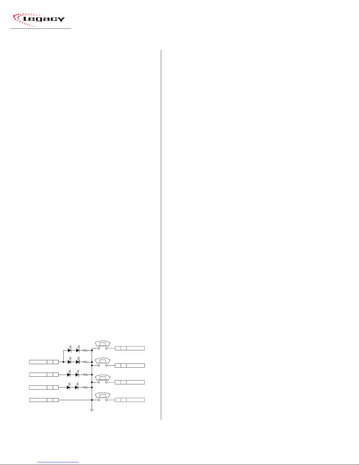
Mic Control Panel
(Simplified Schematic
for PRE99-1197 or PRE99-1198)
TAL KB ACK
COUGH
ON
OFF
S1
8 J1 TALK TO C/R
S2
7 J1 COUGH
S4
6 J1 ON
S3
5 J1 OFF
AMBER (TALKBACK)
AMBER (COUGH)
V+ SUPPLY J1 4
ON TALLY J1 3
OFF TALLY J1 2
LOGIC GND J1 1
AMBER (OFF)
CR3 CR6
CR4 CR5
RED (ON)
CR8 CR7
CR1 CR2
GNDD
J1: TO/FROM CONSOLE CHANNEL LOGIC
All LEDs are tied to Logic Ground (pins 1, 2 or 3
on the LOGIC I/O connector).
To construct a custom mic control panel like
that shown on this page, use SPST (single pole,
single throw) momentary contact switches with
LED or lamp indicators. Lamps must be 6.3 v olt
type with a current draw of under 50 mA.
Tie one side of each switch and lamp to Logic
Common (pin 1, 2 or 3 on the LOGIC I/O connector). The other side of the Cough and Talkback
lamps tie together to Logic Active T ally (pin 15).
Each switch is tied to its logic counterpart (the
On switch goes to the On (-) input, pin 7, the Off
switch goes to Off (-) input, pin 8, etc.). T he on/off
lamps are tied to their Tally outputs (On lamp to
On Tally, pin 17; Off lamp to Off Tally, pin 16).
Tally Common (pin 14) is jumpered to Logic
Supply +5VDC (pin 6, 10, 11 or 12) at the LOGIC
I/O connector. Pin 18, Activate Logic Inputs (+)
is also jumpered to Logic Supply +5VDC (typically pin 6 is used).
Input Module Logic (Universal Input and
T elc o ) and Per ipheral De vices
Peripheral devices are controlled through the
Start and Stop Command Pulses, or through the
Start Command Sustained logic, and the Commands Common connections.
In the basic logic connection example on pages
2-52 and 2-53, activ e low logic is used, thus Command Common is connected to the logic ground
on the peripheral device (labeled Command Common on the Denon CD player in the example).
In the complex logic example shown on pages
2-54 and 2-55, active high logic is used, thus
Command Common connects to Logic Supply
+5 VDC.
Note: This voltage is more typically supplied
directly by the peripheral device in order to
prevent ground loops.
HARRIS CORPORATION
2-14
Revision B • 1/03
Page 27

2 Installation
Peripheral devices control the module through
the Reset and Ready logic inputs. In the example
on pages 2-52 and 2-53, only the Ready function
is used. The Ready function performs an audio
reset, which turns off the module without generating a Stop Command Pulse. In addition, it also
controls the Off lamp illumination.
In the example on pages 2-54 and 2-55,
Reset (+) and Ready (+) connect to Logic Supply
+5VDC on the module. The Ready (-) command
and the Reset (-) command are pulled low by the
active low logic relay outputs on the peripheral
device, which all tie to the module’ s Logic Ground
(pin 1).
For peripheral devices that require a stead y on
signal, the Start Command Sustained output can
be used.
Additional Logic Connections
There are additional logic connections on the
Meter Switcher module, Control Room module,
and optional Studio module
Three 3-pin connectors on the Meter Switcher
module interface remote timers so they can be
reset by the console timer reset logic. The Meter
Switcher module also has factory-installed cabling
for the timer, the talkback mic, and the digital
level meters. For more information on the Meter
Switcher module’s logic connections and settings,
see pages 2-28 to 2-30.
A 14-pin connector on the Control Room module carries the logic interface for the Control Room
warning light, remote mute and dim inputs, and
the mute, dim and talkback tallies. The 8-pin Cue
Cntl connector on the Control Room module has
the External Cue logic interface. For more information on the Control Room module’s logic connections and settings, see pages 2-32 to 2-36.
The optional Studio module includes a 14-pin
connector to control the studio’s logic, including
warning lights, mutes, and dims. The Studio mod-
ule also has a 16-pin connector for the audio and
logic for an external site’s talkback audio and control. F or more information on the Studio module’ s
logic connections and settings, see pages 2-38 to
2-45.
2-15
HARRIS CORPORATION
Revision B • 1/03
Page 28
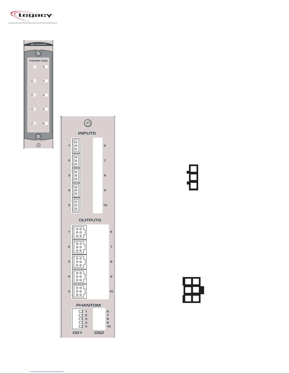
2 Installation
QUICK GUIDE TO THE MICROPHONE PREAMPLIFIER MODULE
Each Legacy Preamplifier module can contain two separate PCAs with five mic preamps on each
assembly. The console comes standard with one Preamp module with one five-input mic preamp PCA
that allows an additional five-input preamp PCA to be retrofitted. A second Mic Preamp (with either
five or ten inputs) can be added to the console.
Each Mic Preamp PCA has five 3-pin analog microphone input connectors and five 6-pin analog
audio output connectors. Each input connects to a separate mic preamp driving its own line-level
balanced analog output connector. The connectors are hidden by the meter panel in normal operation
and the trimpots, visible to the operator, are covered by a security cover.
INPUTS
1 - 10 — The 3-pin analog inputs accept mono microphone signals.
Connect only low impedance, balanced, dynamic or condenser
microphones, with nominal mic output levels of -65 to -30 dBu, to these
inputs.
Analog Mic Inputs
High (+)
Low (-)
Shield
3
2
1
(wire insertion end view)
OUTPUTS
1 - 10 — The 6-pin analog outputs are wired in parallel (mono) using
the standard pinout sequence. This allows these outputs to connect directly
to Universal Input modules without requiring any setting changes be made
to the Input Mode from a standard stereo input. The preamp output signal
level is +4 dBu.
Analog Preamp Outputs
Left Hig h (+ )
Left Low ( - )
Shield
3
6
Right High ( + )
2
5
Right Low (-)
1
4
Shield
HARRIS CORPORATION
(wire insertion end view)
2-16
Revision B • 1/03
Page 29
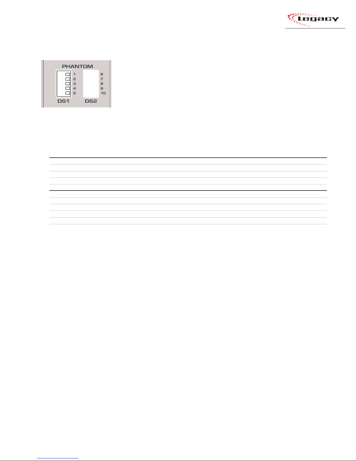
2 Installation
MICROPHONE PREAMPLIFIER MODULE SWITCHES
PHANTOM
DS1 — These five DIP switches control the phantom power for the mic inputs 1 - 5. The factory
default for the phantom power is off per the Microphone Preamplifier Module Switch Definitions
table shown below.
DS2 — These five optional DIP switches set the phantom power for optional mic inputs 6-10.
Microphone Preamplifier Module Switch Definitions
# Switch Name ON Function (set to operator’s left) OFF Function (set to operator's right)
1 Mic Input #1 Phantom power on Phantom power off
2 Mic Input #2 Phantom power on Phantom power off
3 Mic Input #3 Phantom power on Phantom power off
DS1
4 Mic Input #4 Phantom power on Phantom power off
5 Mic Input #5 Phantom power on Phantom power off
6 Mic Input #6 Phantom power on Phantom power off
7 Mic Input #7 Phantom power on Phantom power off
8 Mic Input #8 Phantom power on Phantom power off
9 Mic Input #9 Phantom power on Phantom power off
DS2 (optional)
10 M ic Input #10 Phantom power on Phantom power off
2-17
HARRIS CORPORATION
Revision B • 1/03
Page 30
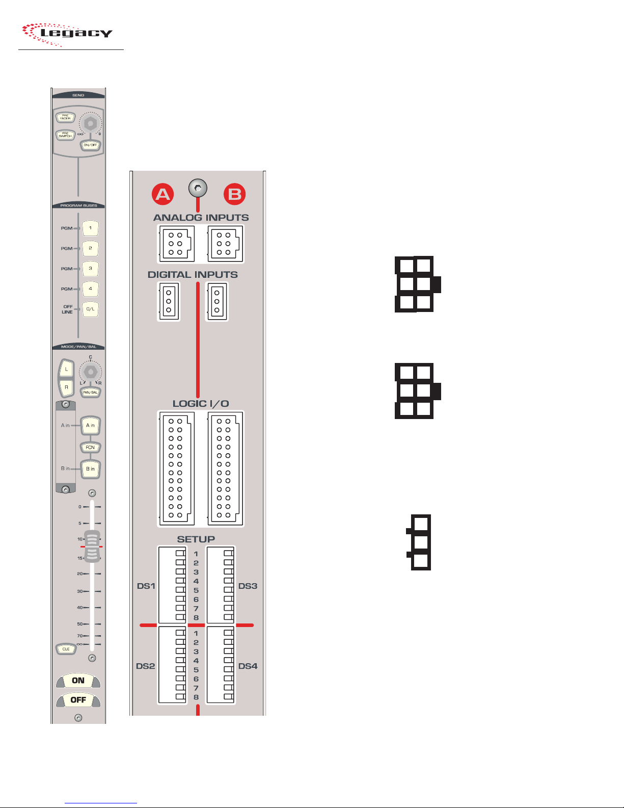
2 Installation
QUICK GUIDE TO THE UNIVERSAL INPUT MODULE
Six connectors come standard on each Universal Input module: two 6-pin analog audio input connectors, two 3-pin digital audio input connectors, and two 24-pin logic connectors. The connectors are
hidden by the meter panel in normal operation.
AUDIO
ANALOG INPUTS A & B — The 6-pin analog inputs accept stereo or
mono line level signals. Mono signals, like those from a preamplified
microphone, should be paralleled to the left and right inputs.
Analog Inputs - Stereo
Left High (+ )
Left Low (- )
Shield
3
6
Right High (+)
2
5
Right Low (-)
1
4
Shield
(wire insertion end view)
Analog Inputs - Mono
3
High (+)
Low (-)
Shield
6
High (+)
2
5
Low (-)
1
4
Shield
(wire insertion end view)
DIGITAL INPUTS A & B — The two 3-pin digital inputs accept AES-3
(AES/EBU) or S/PDIF signals (when the circuit shown on page 2-11 is used).
Digital Inputs
High (+)
Low (-)
Shield
3
2
1
HARRIS CORPORATION
(wire insertion end view)
LOGIC
LOGIC I/O A & B — Two 24-pin logic connectors allow separate A/B
input control of peripheral devices or remote panels connected to the A and
B inputs. For additional information, see pages 2-20 and 2-21
2-18
Revision B • 1/03
Page 31

2 Installation
UNIVERSAL INPUT MODULE SWITCHES
SETUP
DS1/DS2 — These 16 DIP switches affect the logic settings for the A input. Individual switch
definitions are listed below.
DS3/DS4 — These 16 DIP switches affect the logic settings for the B input. Individual switch
definitions are listed below.
Universal Input Module Switch Definitions
# Switch Name ON Function (set to operator’s left) OFF Function (set to operator's right)
1 Signal Source Digital Input connector Analog Input connector
2 C/R Mute Mutes C/R Monitor output at module on
3 Studio Mute Mutes Studio Monitor out put at module o n 1No Studio monitor muting
4 Spare Switch
5 External Site Mute External Mut e log ic out put at module on
DS1/DS3DS2/DS4
6 Console On as Cough Press & hold On button for Cough button On button not used for Cough
7 Timer Reset Resets timer at module on No timer reset
8 Off LED control (Ready) Local (Off LED follows on/off status) Peripheral controls Off LED (Ready logic)
1 Fader Start/Stop Fader movement, from full off, turns Fader movement does not affect
module on; to full off, turns module off module on/off
2 Start/Stop Pulses Multiple (each press of On or Off button S ingle (pulse is only generated when
generates another pulse) changing state, Off to On, On to Off )
3 Start/Stop Control All (pulse is generated no matter where Local (pulse is only generated by
the on/off control originates) module's On or Off buttons)
4 Bypass Sample Rate Bypasses internal SRC (external source Uses internal SRC (normal setting)
Converter (SRC) must run off the same external digital
audio reference as console)
2
5 Spare Switch
6 Spare Switch
7 Input Level Set A See DS2/DS4 table below See DS2/DS4 table below
8 Input Level Set B See DS2/DS4 table below See DS2/DS4 table below
1
No C/R monitor muting
1
No External monitor muting
DS2/DS4 — Switches 7 and 8
These switches are used together to set the level for the input.
78 Analog 3Digital
Off Off +4dBu 0dB
Off On +6dBu -6dB
On Off +8dBu -12dB
On On -10dBV -18dB
1
The module logic is set as a Microphone when any one of these switches is set to On.
2
Refer to page 2-11, Digital Clock Reference for details on an external reference.
3
The nominal input to achieve -20 FSD (equal to a +4 dBu output), with the fader set to the red reference line.
4
The amount of gain reduction applied t o the digital input signal.
4
2-19
HARRIS CORPORATION
Revision B • 1/03
Page 32

2 Installation
UNIVERSAL INPUT MODULE — LOGIC I/O
There are two 24-pin logic interface connectors
on the Universal Input module. The left logic connector controls the device attached to the A input;
the right logic connector controls the device attached
to the B input. The logic connectors are hidden by
the meter panel in normal operation. Pages 2-50 to
2-55 show several connection examples.
Note that the Ready and Reset commands are
balanced inputs (they have both a + and - input),
thus for a switch input the + input has to be tied to
Logic Supply +5VDC and the switch tied to Logic
Ground.
Outputs marked with an * are only available when
the module has a Rev. C or later SPROM (21-227-
7). When DS1 (for input A) or DS3 (for input B)
switches 2, 3, or 5 are set to on, then the MIC logic
function is enabled. When switches 2, 3, and 5 are
set to off, then the Line logic function is enabled.
Logic Connectors
Logic Supply +5VDC
Logic Supply +5VDC
Logic Supply +5VDC
Cough (-)
Off (-)
On (-)
Logic Supply +5VDC
Start Command Pulse
Stop Command Pulse
Logic Ground
Logic Ground
Logic Ground
(wire insertion end view)
12
11
10
LINE: Ready (+) MIC: Talk to EXT (+)
24
Start Command Sustained
23
LINE: Reset (+) MIC: Talk to Studio (+)
22
LINE: Ready (-) MIC: Talk to EXT (-)
21
9
*LINE: E x t. Cue (-) MIC: Talk to C/R (-)
20
8
LINE: Reset (-) MIC: Talk to Studio (-)
19
7
Activate Logic Inputs (+)
18
6
On Tally
17
5
Off Tally
16
4
*LINE: Cue Tally MIC: Logic Active Tally
15
3
Tally Common
14
2
Command Common
13
1
Universal Input Module, Logic I/O — Simplified Logic Diagram
MIC: Talk to Studio (+) LINE: Reset Input (+)
MIC: Talk to Ext. (+) LINE: Ready Input (+)
MIC: Talk to Ext. (-) LINE: Ready Input (-)
MIC: Talk to Studio (-) LINE: Reset Input (-)
Activate Logic Inputs(+)
On Input (-)
Off Input (-)
Cough Input (-)
MIC: Talk To C/R (-) LINE: Cue Input (-)
Notes:
Opto-Isolator inputs can handle +5 to +40 VDC logic
Opto-Isolator outputs can handle up to 60 volts or 350 mA
22
24
21
19
18
7
8
9
20
Start Command Pulse
5
Stop Command Pulse
4
Start Command Sustained
23
Command Common
Internal Logic
+5V
Reg.
13
MIC: Logic Active Tally LINE: Cue Tally
15
On Tally
17
Off Tally
16
Tally Common
14
Logic Groun d
1
Logic Groun d
2
Logic Groun d
3
6
Logic Supply +5VDC
10
Logic Supply +5VDC
11
Logic Supply +5VDC
12
Logic Supply +5VDC
HARRIS CORPORATION
2-20
Revision B • 1/03
Page 33

Universal Input Module, Logic I/O — Signal Definitions
2 Installation
SIGNAL / PIN NUMBER
START COMMAND PULSE
(pin 5)
STOP COMMAND PULSE
(pin 4)
START COMMAND
SUSTAINED (pin 23)
COMMAND COMMON
(pin 13)
ACTIVATE LOGIC INPUTS (+)
(pin 18)
ON (-)
(pin 7)
OFF (-)
(pin 8)
COUGH (-) (pin 9)
TALK TO C/R or CUE (-)
(pin 20)
TALLIES
OFF TALLY (pin 16)
FUNCTIONAL DESCRIPTION
Equivalent to a Normally Open (N/O) contact. A momentary “contact closure” of 220 ms to Command Common
occurs when the module On button is pressed. Typically connects to the Remote Start logic input on the
peripheral device. When DS2/DS4-2 is set to On, each press of the On button generates another contact closure.
Same as the Start Command Pulse, except it is initiated by the module Off button. Typically connects to the
Remote Stop or Pause logic input on the peripheral device.
A maintain ed contact closure wit h Co mm a nd Com m on for a s l on g a s t h e m odu le is on . Typically conne ct s to t he
Remote Start logic input on a peripheral device that cannot use a start pulse.
The Common (C) relay contact output for the three Start and Stop Command outputs. Sets whether the Start
and Stop Commands are active high (connect this pin to the logic supply voltage on the peripheral device) or
active low (connect this pin to logic ground on the peripheral device).
To enable the control inputs: On, Off, Cough, Talk/Ext Cue, tie thi s p in to + log ic vo lt ag e (+ 5 to + 40 ) . When tied to
an isolated device like a mic remote panel, use the Logic Supply +5VDC (jumper pin 18 to pin 6, 10, 11 or 12).
When pulled low, turns the module on from off, generating a Start Pulse if DS2/DS4-3 is set to On. It is ignored if
the module is already on, unless DS2/DS4-2 is set On (then each On button press generates a Start Pulse).
When pulled low, turns the module off from on, generating a Stop Pulse if DS2/DS4-3 is set to On. It is ignored if
the module is already off, unless DS2/DS4-2 is set On (then each Off button press generates a Stop Pulse).
When pulled low, mutes the audio from all assigned buses, for as long as the Cough button is pressed.
When pulled low, and the module is set as a Mic, the input audio is muted from all output buses and only routed
to the C/R talkback bus. When set as a Line, routes the input audio to the Cue bus while the input is low.
All Tally outputs are N/O “dr y contact” type outputs. Typically used to drive indicators, the outputs can sink or
source up to 60 volts at 350 mA. The “C” or common contact for all the tallies is Tally Common (pin 14).
This output connects to Tally Common while the module is off when DS1/DS3-8 is set to On. When DS1/DS3-8 is
set to Off, then this output is controlled by the Ready logic.
ON TALLY (pin 17)
LOGIC ACTIVE TALLY or
CUE TALLY (pin 15)
TALLY COMMON
(pin 14)
READY / TALK TO EXT.
RESET / TALK TO STUDIO
(+) & (-)
READY (+) & (-)
(pins 24 & 21)
RESET (+) & (-)
(pins 22 & 19)
TALK TO EXTERNAL (+) & (-)
(pins 24 & 21)
TALK TO STUDIO (+) & (-)
(pins 22 & 19)
LOGIC SUPPLY +5VDC
(pins 6, 10, 11, 12)
LOGIC GROUND
(pins 1, 2, 3)
This output connects to Tally Common while the module is on.
This output connects to Tally Common when the module is set as a Mic and the matching A or B input is
selected. When set as a Line input, the output is connected to Tally Common while Cue is active.
The Common (“C”) contact for the three tally outputs, it must be tied high or low to provide the return path for
the tallies. Typically, the tally lamps/LEDs are all tied to ground and Tally Common connects to the lamp supply
voltage (+5 to +60 VDC). If the tallies are tied to +VDC, then this pin would tie to ground.
These complementary logic inputs require +5 to +40 VDC between the (+) input and the (-) input for activation.
This can be done by connecting an active high logic to the (+) input and grounding the (-) input, or by supplying
+5 to +40 VDC to the (+) input and an active low logic (like a switch to ground) to the (-) input.
This function is active when the module is set as a Line Input (DS1/DS3 switches 2, 3, & 5 are all off). When
activated while the module is on, turns the module off without generating a stop pulse. When activated while
the module is off, it controls the Off LED to indicate device status. Typically, LED off indicates the peripheral is not
ready to play, a steady on LED indicates the device is ready, and a flashing LED indicates the device has already
played or is not yet cued up.
This function is active when a module is set as a Line Input (DS1/DS3 switches 2, 3, & 5 are all off). When
activated while the module is on, turns the module off without generating a stop pulse. Input is ignored if the
module is already off.
This function is active when a module is set as a C/R or Studio Mic Input (DS1/DS3 switch 2 or 3 is set on). Can be
activated while the module is on or off (when on, it mutes the bus audio), to talk to an External location.
This function is active when a module is set as a C/R or External Mic Input (DS1/DS3 switch 2 or 5 is set on). Can
be activated while the module is on or off (when on, it mutes the bus audio), to talk to the Studio.
Module logic voltage output sources that can deliver up to 300 mA of current to isolated control panels. All pins
are simply paralleled for convenience.
Module logic ground. Should be connected t o isolated control panels only.
2-21
HARRIS CORPORATION
Revision B • 1/03
Page 34

2 Installation
QUICK GUIDE TO THE TELCO/C ODEC MODULE
There are three connectors on the optional Telco module: one 6-pin analog audio input connector,
one 3-pin digital audio input connector, and one 24-pin logic connector. The connectors are hidden by
the meter panel in normal operation.
AUDIO
ANALOG INPUT — The 6-pin analog input accepts line level stereo or
mono signals. When a mono signal is connected, parallel the signal to the
left and right input pins.
Analog Inputs - Stereo
Left Hig h (+ )
Left Low ( - )
Shield
3
6
Right High ( + )
2
5
Right Low (-)
1
4
Shield
(wire insertion end view)
Analog Inputs - Mono
High (+)
Low (-)
Shield
(wire insertion end view)
DIGITAL INPUT — The 3-pin digital input accepts AES-3
(AES/EBU) or S/PDIF signals (when the circuit shown on page 2-11 is used).
3
6
High (+)
2
5
Low (-)
1
4
Shield
Digital Inputs
High (+)
Low (-)
3
2
HARRIS CORPORATION
Shield
1
(wire insertion end view)
LOGIC
LOGIC I/O — The 24-pin logic connector allows control of the connected
device by the module, or external control of the module by the device. Logic
settings are configured by the Setup DIP switches (see Switch Definitions on
page 2-23). Additional logic information is on pages 2-24 and 2-25.
2-22
Revision B • 1/03
Page 35

2 Installation
TELCO MODULE SWITCHES
SETUP
DS1 / DS2 —DS1 / DS2 —
DS1 / DS2 — These 16 DIP switches set logic functionality for the module, per the T elco Module Switch
DS1 / DS2 —DS1 / DS2 —
Definitions table below.
T elc o / C odec Module Swit ch Definitions
# Switch Name ON Function (set to the operator’s left) OFF Function (set to the operator's right)
1 Set Telco ID On (sets the module as Telco / Codec #1)
2 Set Telco ID On (sets the module as Telco / Codec #2)
3 Set Telco ID On (sets the module as Telco / Codec #3)
4 Set Telco ID On (sets the module as Telco / Codec #4)
DS1
5 Spare Switch
6 Spare Switch
7 Signal Source Digital Input Analog Input
8 Timer Reset Resets timer at module on No timer reset
1
Off
1
Off
1
Off
1
Off
1 Off Lamp Control L o cal (Off lamp follows module on/off status) Ready (External device controls lamp)
2 Fader Start/Stop Fader movement, from full off, turns Fader movement does not affect
module on; to full off, turns module off. module on/off
3 Sample Rate Bypasses the internal SRC (use only Uses internal SRC (normal setting)
Converter (SRC) when the console and all the audio
2
4 Spare Switch
DS2
sources are locked to an external reference)
5 Spare Switch
6 O/L & Record Source Pre-fader with module off (if Meter Post-fader regardless of module on/off
Switcher switch 6 is set for Pre-Fader)
7 Input Level See DS2 table below See DS2 table below
8 Input Level See DS2 table below See DS2 table below
DS2 — Switches 7 and 8
These switches are used together to set the nominal input level. The factory default is both OFF.
7 8 Analog
Off Off +4dBu 0dB
Off On +6dBu -6dB
On Off +8dBu -12dB
On On -10dBV -18dB
1
Cautio n: Set only one of these four DIP switches to On. Each Telco module in the console MUST have a unique ID
setting. This setting identifies the module, affecting both signal routing and module controls.
2
Refer to page 2-11, Digital Clock Reference for details.
3
The nominal analog input to achieve -20 FSD (equal to a +4 dBu output), with the fader set to the red reference line.
4
The amount of gain reduction applied to the digital input.
3
Digital
4
2-23
HARRIS CORPORATION
Revision C • 2/04
Page 36

2 Installation
TELCO MODULE — LOGIC I/O
There is one 24-pin logic connector on the Telco
module to control the connected device.
To activate the remote inputs (On, Off, Cough,
Talk to Caller) jumper pin 18 (Activate Logic Inputs) to +VDC on the remote device, or to pin 6
(Logic Supply +5VDC) when a remote panel is used.
The T alk to Caller (-) logic input allows the board
operator to talk to the caller. When this input is
pulled low , the console-mounted talkback mic is sent
to the left channel of the Mix-Minus output for this
caller on the Output 1 module. The right channel
mix-minus output is not affected by talkback.
Logic Connectors
Logic Supply +5VDC
Logic Supply +5VDC
Logic Supply +5VDC
Cough (-)
Off (-)
On (-)
Logic Supply +5VDC
Start Command Pulse
Stop Command Pulse
12
11
10
Ready (+)
24
Start Command Sustained
23
Reset (+)
22
9
8
7
6
5
4
Ready (-)
21
Talk to Calle r (-)
20
Reset (-)
19
Activate Logic Inputs (+)
18
On Tally
17
Off Tally
16
Telco Module, Logic I/O — Simplified Logic Diagram
Reset Input (+)
Ready Input (+)
Ready Input (-)
Reset Input (-)
Activate Logic Inputs(+)
22
24
21
19
18
Logic Ground
Logic Ground
Logic Ground
(wire insertion end view)
Internal Logic
3
2
1
Talk Tally
15
Tally Common
14
Command Common
13
Start Command Pulse
5
4 Stop Command Pulse
Start Command Sustained
23
Command Common
13
15
Tal k Tal ly
On Tally17
On Input (-)
Off Input (-)
Cough Input (-)
Talk To Caller Input (-)
Notes:
Opto-Isolator inputs can handle +5 to +40 VDC logic
Opto-Isolator outputs can handle up to 60 volts or 350 mA
7
8
9
20
HARRIS CORPORATION
2-24
Revision B • 1/03
+5V
Reg.
16
Off Tally
Tally Common
14
Logic Groun d
1
Logic Groun d
2
Logic Groun d
3
Logic Supply +5VDC
6
Logic Supply +5VDC
10
Logic Supply +5VDC
11
12
Logic Supply +5VDC
Page 37

Telco/Codec Module, Logic I/O — Signal Definitions
2 Installation
PIN NAME/NUMBER
START COMMAND PULSE
(pin 5)
STOP COMMAND PULSE
(pin 4)
START COMMAND
SUSTAINED
(pin 23)
COMMAND COMMON
(pin 13)
ACTIVATE LOGIC INPUTS (+)
(pin 18)
ON (-)
(pin 7)
OFF (-)
(pin 8)
COUGH (-)
(pin 9)
TALK T O CALLER (-)
(pin 20)
FUNCTIONAL DESCRIPTION OF CONNECTION
Normally Open (N/O) contact output. A momentary “contact closure” of 220 ms to Command Common occurs
when the modu l e s t at u s c h a n g e s to O n f rom Off. Typically connec ts to the Remote Sta rt logic input on the
peripheral d evice.
Normally Open (N/O) contact output. A momentary “contact closure” of 220 ms to Command Common occurs
when the modu l e s t at us c h a n g e s to Off from On. Typica l l y co n ne cts to the Remote Sto p o r Pause logic input on
the peripheral device.
Normally Open (N/O) contact output. A “contact closure” to Command Common occurs while the module is On.
Typically connec t s to the Remote Start log i c i n p u t o n a peripheral device that ca n no t u se p u l se s.
The Common (C) contact output for the Start and Stop commands. For an active high logic on the command
outputs, connec t Command Common to the logic supply voltage on the peripheral device. For an active low
logic on the command outputs, connec t this pin to logic ground on the peripheral device.
Connecting +5 to +40 VDC to this input enables the active low ext ernal control inputs (On, Off, Cough, Talkback).
If the control inputs are isolated from other devices (e.g., on a control panel), the +VDC can come from +5 Lo gic.
When pulled low, turns the module On from O ff. Input is ignored if the module is already on.
When pulled low, turns the module Off from On. Input is ignored if the module is already off.
When pulled low, the module audio is muted from all assigned buses.
When pulled low, the console talkback mic audio is routed to the telco mix-minus output for this module.
TALLIES
OFF TALLY
(pin 16)
ON TALLY
(pin 17)
TALK TALLY
(pin 15)
TALLY COMMON
(pin 14)
READY (+) & (-)
RESET (+) & (-)
READY (-) & (+)
(pins 21 & 24)
RESET (-) & (+)
(pins 19 & 22)
LOGIC SUPPLY +5VDC
(pins 6, 10, 11, 12)
The Tally outputs are N/O “dry contac t ” outputs. Typically used to drive indicator lamps or LEDs, the outputs can
sink or source up to 60 volts or 350 mA. The “C ” contact for all the tally outputs is Tally Common.
While the module is off, the Off Tally output connects to Tally Common—if Ready (DS1/DS3-1) is set to On. When
DS1/DS3-1 is set to Off, then the Off Tally is controlled by the Ready input logic.
While the module is on, the On Tally output connects to Tally C ommon.
While the Talk to Caller input is pulled low, the Talk Tally output connects to Tally Common.
The “C” relay contact for the Off, On, and Talk tallies. Typically, the tally lamps/LEDs are tied together to ground
and Tally Common connects to the lamp supply voltage (up to 60 volts). If the tallies use +6.3 volt, 40 mA lamps,
and are isolated from peripheral devices (as in a remote mic control panel), then the Tally Common can come
from Logic Supply +5 Logic.
These complementary logic inputs require +5 to +40 VDC between the (+) input and the (-) input for activation.
This can be done by connecting an active high logic to the (+) input and grounding the (-) input, or by supplying
+5 to +40 VDC to the (+) input and an active low logic to the (-) input.
When activated while the module is on, the module turns off without generating a stop pulse. While the module
is off, the Ready logic controls the Off L ED to indicate device status. Typically, LED off indicates the peripheral is
not ready to play, LED on indicates the device is ready, and a flashing LED indicates the device has already played
or has not been cued up.
When activated while the module is on, turns the module off without generating a stop pulse. Input is ignored if
the module is already off.
Module logic voltage output source that can deliver up to 300 mA of current.
LOGIC GROUND
Module logic ground.
(pins 1, 2, 3)
2-25
HARRIS CORPORATION
Revision B • 1/03
Page 38

2 Installation
QUICK GUIDE TO THE REMO TE LINE SELECT OR (RLS) MODULE
There are ten connectors on each optional Remote Line Selector (RLS) module: eight 6-pin audio
input connectors and two 6-pin audio output connectors. All connectors are set for either analog or
digital signals. The connectors are hidden by the meter panel in normal operation.
ANALOG OR DIGITAL INPUTS
1 - 8 — The 6-pin input connectors can accept either all analog (stereo or
ANALOG OR DIGITAL
INPUTS
1
mono) signals or all digital AES-3 (AES/EBU) compatible signals (signal
type set using a module DIP switch). When an analog mono input is
connected, parallel the signal to both the left and right inputs. For a digital
input, connect the AES-3 signal to pins 1, 2, and 3 only.
2
3
4
5
6
7
8
OUTPUTS
1
Analog Inputs - Stereo
Left Hig h (+ )
Left Low (-)
Shield
(wire insertion end view)
3
2
1
Analog Inputs - Mono
High (+)
Low (-)
Shield
(wire insertion end view)
6
3
5
2
4
1
Digital Inputs/Outputs
High (+)
Low (-)
Shield
3
6
2
5
1
4
6
5
4
Right High (+)
Right Low (-)
Shield
High (+)
Low (-)
Shield
no connection
no connection
no connection
2
HARRIS CORPORATION
(wire insertion end view)
OUTPUTS
1 & 2 — The 6-pin outputs are either both analog or both digital (signal
type set using a module DIP switch).
2-26
Revision B • 1/03
Page 39

2 Installation
REMOTE LINE SELECT OR (RLS) MODULE SWITCHES
SETUP
1 - 5 — DIP switch 1 sets the module for either analog or digital operation. The default setting
is off (analog). The other switches are not used.
Remote Line Selector (RLS) Module Switch Definitions
# Switch Name ON Function (set to operator’s left) OFF Function (set to operator's right)
1 Signal Source Digital Analog
2 Spare Switch
3 Spare Switch
4 Spare Switch
5 Spare Switch
2-27
HARRIS CORPORATION
Revision B • 1/03
Page 40

2 Installation
QUICK GUIDE TO THE METER SWITCHER MODULE
There are three user connections—3-pin external timer logic connectors, on the Meter Switcher. The
two To Meter Panel connectors are factory connected. All connectors are hidden by the meter panel in
normal operation.
EXT TIMER
1, 2, 3 — Each 3-pin External Timer connector can be used to reset an
external digital timer. For pinout, see page 2-30.
TO METER PANEL
METERS — Factory harnessed connector for the digital signal meters.
TIMER/TB MIC — Factory harnessed connector for the digital timer
and the console talkback microphone.
HARRIS CORPORATION
2-28
Revision B • 1/03
Page 41

2 Installation
METER SWITCHER MODULE SWITCHES
SETUP
1 - 8 — These eight DIP switches affect various logic settings for the console per the Meter
Switcher Module Switch Definitions table below.
Meter Switcher Module Switch Definitions
# Switch Name ON Function (set to operator’s left) OFF Function (set to operator's right)
1 Spare Switch
2 Spare Switch
3 Cancel Cue Cue function for that channel is turned Cue is not affected when the module
at Module On off when the module is turned On is turned On
4 Cue LED Blink Cue LED blinks while Cue is on Cue LED is solid while Cue is on
5 Spare Switch
6 Off-Line Signal The Off-Line audio feed level is The Off-Line audio feed is not affected by the
Level controlled by the fader (post-fader) module fader (pre-fader)
7 Spare Switch
8 Spare Switch
CONSOLE RESET
RESET
(SEE MANUAL) — This push-button switch resets the installed input and monitor modules
to their factory default settings without powering down the console. Typically, this switch is
used only for test purposes since it does not reset the DSP cards.
2-29
HARRIS CORPORATION
Revision B • 1/03
Page 42

2 Installation
METER SWITCHER MODULE — EXTERNAL TIMER
The three 3-pin external timer connectors
have identical signals and connector pin outs.
They function in parallel with the console timer,
although only the auto reset command is active (e.g., external timer reset is only triggered
by a module timer reset command).
Meter Switcher Module, External Timer — Simplified Logic Diagram
+3.3VDC
2
Auto Reset Command
EXT TIMER 1
Auto Reset Common
3
2
Auto Reset Command
EXT TIMER 2
Auto Reset Common
Internal Logic
3
2
Auto Reset Command
EXT TIMER 3
Auto Reset Common
3
Notes:
There are no connections to pin 1.
Logic Connectors
Timer Reset Common
Timer Reset Command
no connection
(wire insertion end view)
3
2
1
Opto-Isolated outputs can sink up to 60 volts or
350 mA max. current flow.
Meter Switcher Module, Ex ternal Timer — Signal Definitions
PIN NAME/NUMBER
TIMER RESET COMMAND
(pin 2)
TIMER RESET COMMON
(pin 3)
FUNCTIONAL DESCRIPTION OF CONNECTION
A module timer reset command shorts this pin to Pin 3.
A module timer reset command shorts this pin to Pin 2.
2-30
HARRIS CORPORATION
Revision B • 1/03
Page 43

BLANK PAGE
2 Installation
2-31
HARRIS CORPORATION
Revision B • 1/03
Page 44

2 Installation
QUICK GUIDE TO THE CONTROL ROOM MODULE
There are thirteen connectors on the Control Room module: five 6-pin analog audio input connectors, six 6-pin analog audio output connectors , one 14-pin logic connector, and one 8-pin logic connector. The connectors are hidden by the meter panel in normal operation.
INPUTS
EXT-1, EXT-2, EXT-3, EXT-4, CUE IN — The 6-pin analog inputs
accept stereo signals or mono signals from up to four external sources and
a cue source. When a mono signal is connected, parallel the signal to the
left and right input pins.
Analog Inputs - Stereo
Left Hig h (+ )
Left Low (- )
Shield
3
2
1
6
5
4
Right High ( + )
Right Low (-)
Shield
(wire insertion end view)
Analog Inputs - Mono
High (+)
Low (-)
Shield
(wire insertion end view)
3
6
High (+)
2
5
Low (-)
1
4
Shield
OUTPUTS
MONITOR, OPERATOR , CO-HOST, GUEST, CUE, T A L K BACK
— The 6-pin balanced stereo analog outputs are wired using the standard
pinout sequence.
Analog Outputs
Left Hig h (+ )
3
6
Right High ( + )
HARRIS CORPORATION
Left Low ( - )
Shield
2
5
Right Low (-)
1
4
Shield
(wire insertion end view)
LOGIC
LOGIC — This 14-pin connector has the warning light control output,
remote inputs for C/R mute and dim, and control outputs for talkback,
mute, and dim indicators. For more information, see pages 2-34 & 2-35.
CUE CNTL — This 8-pin connector has an external cue control input.
For more information, see page 2-36.
2-32
Revision B • 1/03
Page 45

2 Installation
CONTROL ROOM MODULE SWITCHES
SETUP
SETUP — These eight DIP switches affect logic functionality for the module per the Control
Room Module Switch Definitions below.
Control Room Module Switch Definitions
# Switch Name ON Function (set to operator’s left) OFF Function (set to operator's right)
1 Operator Headphone Cue feeds left channel, monitor feeds right, Stereo Cue is fed to Operator output
AutoCue function while Cue is active and AutoCue is On while Cue is active and AutoCue is On.
2 Talkback into Co-Host Talkback to C/R also fed to the Does not route talkbac k to C/ R to the
Headphone Co-Host headphone output Co-Host headphone output
3 Talk back into Cue Talkback to C/R is added to the Talkback to C/R does not feed the
Cue output Cue output (only feeds Talkback output)
4 Dim Monitors when Dims monitors by 12 dB when receiving Does not dim monitors when receiving
Receiving Talkback Talk to C/R signal Talk to C/R signal
5 Auto-switch External Performs automatic switching from Does not perform automatic switching
Inputs 1 & 2 * Ext. Input 1 to Ext. Input 2 while there is a
live mic in the Control Room
6 Auto-switch External Performs automatic switching from Does not perform automatic switching
Inputs 3 & 4 * Ext. Input 3 to Ext. Input 4 while there is a
live mic in the Control Room
7 Spare Switch
8 Spare Switch
* Switch 5 (or 6), when set to On, automatically switches the Operator, Co-Host, and Guest headphone outputs between an
air monitor signal on External Input 1 (or External Input 3), which has an objectionably long propagation delay , with a
synthetic air signal (with relatively little delay) connected to External Input 2 (or External Input 4). Note that to do this the
monitor source must be set to External Input 1 (or External 3).
2-33
HARRIS CORPORATION
Revision B • 1/03
Page 46

2 Installation
CONTROL ROOM MODULE — LOGIC
The 14-pin Logic connector has the warning
light output “relay,” the remote mute and dim
control inputs, and three indicator outputs (talkback, dim, mute).
Pins 4 and 5 offer an isolated contact pair
for triggering an external warning lamp interface.
To use the remote inputs (Dim, on pin 9; Mute
on pin 8), pin 14 (Activate Logic Inputs) must
be tied to Logic Supply +5VDC (pin 6 or 7), or
if an external device rather than a switch is
activating these inputs, then this voltage should
come from the external device to keep the console isolated.
Logic Connectors
Logic Supply +5VDC
Logic Supply +5VDC
War ning Relay
War ning Relay
Logic G round
Logic G round
Logic G round
(wire insertion end view)
7
14
Activate Logic Inputs (+)
6
13
Talkback Tally
5
12
Dim Tally
4
11
Mute T ally
3
10
Mute, Dim & T/B Tally Common
2
9
Dim Input (-)
1
8
Mute Input (-)
Control Room Module, Logic — Simplified Logic Diagram
Activate Logic Inputs (+)
Mute Input (-)
Dim Input (-)
Notes:
Opto-Isolated inputs are current limited and work
with +5 to +40 VDC logic.
Opto-Isolated outputs can sink up to 60 volts or
350 mA max. current flow.
14
8
9
Internal Logic
Warning Relay
4
Warning Relay
5
Dim Tally
12
Mute Tally
11
Talkback Tally
13
Tallies Common
10
Logic Ground
1
Logic Ground
2
Logic Ground
3
Logic Supply +5VDC
7
Logic Supply +5VDC
6
HARRIS CORPORATION
2-34
Revision B • 1/03
Page 47

Control Room Module, Logic — Signal Definitions
PIN NAME/NUMBER
FUNCTIONAL DESCRIPTION OF CONNECTION
2 Installation
TALKBACK TALLY
(pin 13)
WARNING RELAY
(pins 4 and 5)
ACTIVATE LOGIC INPUTS (+)
(pin 14)
MUTE INPUT (-)
(pin 8)
DIM INPUT (-)
(pin 9)
MUTE TALLY
(pin 11)
DIM TALLY
(pin 12)
MUTE, DIM & T/B TALLY
COMMON
(pin 10)
LOGIC SUPPLY +5VDC
(pins 6 and 7)
LOGIC GROUND
(pins 1, 2, 3)
Normally Open (N/O) contact output. A contact closure is generated while there is talkback to the Control Room.
The Common (C) contact is the Mute, Dim & T/B Tally Common output.
Isolated, Normally Open (N/O) and Common (C) contact outputs. A “contact closure” is generated anytime a
Control Room mic module is On-Air (assigned to any Program bus and turned On) or an External Mute command
is being received.
Connecting +5 to +40 VDC to this input enables the active low external control inputs Mute and Dim. If the
inputs are isolated (e.g., on a remote control panel), the +VDC can come from Logic Supply +5VDC.
Mutes the Control Room monitors and triggers the Warning Relay when pulled low.
Dims the Control Room monitors by 12 dB when pulled low.
Normally Open (N/O) contact output. A contact closure is generated anytime a Control Ro om mic module is OnAir (assigned to any Program bus and turned On), a possible mic feedback condition exists, or an External Mute is
received. The Common (C) contact is th e Mute, Dim & T/B Tally Common output.
Normally Open (N/O) contact output. A contact closure is generated whenever the C/R monitors are dimmed by
talkback or by an external Dim command. The Common (C) contact is the Mute, Dim & T/B Tally Common output.
The Common (C) contact output for the Mute, Dim, and Talkback tally outputs. When the tallies are all wired
together to ground, this pin ties to a supply voltage. I f all the tallies are tied to a supply voltage then this pin is
tied to a ground. When the tallies are isolated (e.g., on a remote panel) and consist of 5 volt LEDs or 6.3 volt/50 to
100 mA lamps, then the tallies are tied to Logic Ground and this pin is jumpered to Logic Supply +5VDC.
Module logic voltage output source that can deliver up to 300 mA of current. The pins are simply paralleled for
convenience.
Module logic ground. Use only on isolated ground devices like a control panel.
2-35
HARRIS CORPORATION
Revision B • 1/03
Page 48

2 Installation
g
CONTROL ROOM MODULE — CUE CNTL
This 8-pin connector controls whether the External Cue audio input feeds the Cue bus.
To route the External Cue audio to Cue using a remote panel, jumper pin 3 (Cue +) to pin
4 (Logic Supply +5VDC). Connect a single pole
switch to Pin 2 (Cue -) and pin 1 (Logic
Ground).
If an external device (like a Digital Delivery
System) is used to trigger the External Cue, do
not connect to pins 1 and 4. All logic voltages
and ground must come from the external device. For low logic, connect the logic signal to
pin 2 and a voltage source to pin 3. For high
logic, connect the logic signal to pin 3 and tie
pin 2 to logic ground.
Logic Connectors
Logic Supply +5VDC
Cue (+)
Cue ( - )
Logic G round
(wire insertion end view)
no connection
8
4
no connection
7
3
no connection
6
2
no connection
5
1
Control Room Module, Cue Control — Simplified Logic Diagram
Cue Input (+)
Cue Input (-)
3
2
Notes:
Opto-Isolated inputs are current
limited and work with +5 to +40 VDC
ic.
lo
Control Room Module, Cue Control — Signal Definitions
PIN NAME/NUMBER
CUE INPUT (+) & (-)
(pins 3 & 2)
LOGIC SUPPLY +5VDC
(pin 4)
FUNCTIONAL DESCRIPTION OF CONNECTION
When activate d, adds the Ex ternal Cue input to th e Cue bus. These co mp l em e nt a ry logic inputs requi re +5 to + 40
VDC on the (+) input and ground on the (-) input for activation. This can be done by connecting an active high
logic to the (+) input and grounding the (-) input, or by supplying +5 to +40 VDC to the (+) input and an active
low logic to the (-) input.
Module logic voltage output source that can deliver up to 300 mA of current. Use only on isolated ground
devices like a control panel.
Internal Logic
4
+5 VDC Supply
Logic Ground
1
LOGIC GROUND
(pin 1)
Module logic ground. Use only on isolated ground devices like a control panel.
HARRIS CORPORATION
2-36
Revision B • 1/03
Page 49

BLANK PAGE
2 Installation
2-37
HARRIS CORPORATION
Revision B • 1/03
Page 50

2 Installation
QUICK GUIDE TO THE STUDIO MODULE
Six connectors are on the optional Studio module: four 6-pin analog audio output connectors, one
14-pin studio logic connector , and one 16-pin external logic connector. All audio outputs ha ve the same
audio source(s), selected using the eleven Studio source selector buttons. All connectors are hidden by
the meter panel in normal operation.
AUDIO OUTPUTS
MONITOR — This 6-pin analog output connects to the amplifier for the
studio or voice booth speakers. Its output level is controlled by the MONITOR
LEVEL control on the module, or by a Studio Monitor Panel, PRE99-1190
with a Dual Fader Panel, PRE99-1192. The output is wired using the
standard pinout sequence shown below.
HOST, CO-HOST, GUEST — These 6-pin analog outputs send audio
to the headphone amplifiers for the Host, Co-Host, and/or Guest in a studio
or voice booth. The Host output also has Talk to Studio audio, whereas the
Guest output only has the selected Studio Monitor source audio. The CoHost output can follow the Host output or be set to only output Talk to Studio
audio (SETUP switch 5 determines this setting). The outputs are wired using
the standard pinout sequence shown below.
Analog Outputs
Left Hig h (+ )
Left Low ( - )
Shield
(wire insertion end view)
3
6
Right High ( + )
2
5
Right Low (-)
1
4
Shield
LOGIC
LOGIC — This 14-pin connector has the control output for the studio
warning light interface and remote logic inputs for studio monitor dimming
and muting. See pages 2-40 & 2-41 for details.
EXTERNAL — This 16-pin connector has the talkback controls allowing
an external location to talk to the control room and to the studio. It also has
the talkback audio, both to and from the external site. Pages 2-42 to 2-45
detail the various functions.
HARRIS CORPORATION
2-38
Revision B • 1/03
Page 51

2 Installation
STUDIO MODULE SWITCHES AND MIC TRIMS
SETUP
SETUP — These eight DIP switches affect logic settings for the module per the Switch Definitions
table below.
MIC TRIM
CONSOLE — Sets the level of the console talkback mic into the Talk to Studio and Talk to
External outputs.
EXTERNAL — Sets the level of the External location talkback mic into the Control Room and
Studio talkback outputs.
Studio Module Switch Definitions
# Switch Name ON Function (set to operator’s left) OFF Function (set to operator's right)
1 Auto-switch Performs automatic switching from Does not perform automatic switching
External 1 & 2
2 Auto-switch Performs automatic switching from Does not perform automatic switching
External 3 & 4
3 Spare switch
4 Spare switch
5 Co-Host receives The Co-Host output has Talk to Studio Co-Host output has the same signals as the
talkback only audio only, muting the selec tor audio Host output
6 Spare switch
7 External mute/dim External logic connector pins 4 and 5 External logic connector pins 4 and 5
enable
8 Spare Switch
1
Ext. Input 1 to Ext. Input 2 while there is a
live mic in the Studio or voice booth
1
Ext. Input 3 to Ext. Input 4 while there is a
live mic in the Studio or voice booth
2
function as the logic outputs External function as Talk to Studio and Talk
Mute and External Dim (used with an to Studio Host logic inputs
external control devic e)
1
Switch 1 (or 2), when set to On, automatically switches the Host, Co-Host, and Guest headphone outputs between an air
monitor signal on External Input 1 (or Ext ernal Input 3), which has an objectionably long propagation delay , with a
synthetic air signal (with relatively little delay) connected to External Input 2 (or External Input 4). Note that to do this the
Studio Monitor source must be set to External Input 1 (or E xternal 3).
2
Typically switch 7 is set to On only when a talent microphone (connected to an input module on the console) is at the
External location. In this case talkback control is done through the module logic connector. With no talent mic at the
External location, set the switch to Off. In this case a talkback mic is connected to the External connector pins along with a
talkback control panel.
2-39
HARRIS CORPORATION
Revision B • 1/03
Page 52

2 Installation
STUDIO MODULE — LOGIC
This 14-pin connector has outputs for controlling the studio warning lamp interface and
for lighting tallies when Dim, Mute, or talkback
are active. There are also remote mute and dim
inputs on the connector.
To activate the Remote Studio Dim (Pin 9)
and Remote Studio Mute (Pin 8) inputs, Pin
14 (Activate Logic Inputs) must be jumpered
to +5 to +40 volts. T his voltage is normally supplied from an external device when mute or dim
are actively controlled. If simple switches are
controlling the mute or dim then +5 VDC can
be supplied by Pin 7
Studio Module, Lo gic — Simplified Logic Diagram
Logic Connectors
Logic Supply +5VDC
Logic Supply +5VDC
War ning Relay
War ning Relay
Logic G round
Logic G round
Logic G round
(wire insertion end view)
7
6
5
4
3
2
1
Activate Logic Inputs (+)
14
13
Talkback (T/B) Tally
12
Dim Tally
11
Mute T ally
Mute, Dim, & T/B Tally Common
10
Dim Input (-)
9
Mute Input (-)
8
Warning Relay
4
Activate Logic Inputs (+)
Mute Studio (-)
Dim Studio (-)
Notes:
Opto-Isolated inputs are current limited and work
with +5 to +40 VDC logic.
Opto-Isolated outputs can sink up to 60 volts or
350 mA max. current flow.
14
8
9
Internal Logic
5
Warning Relay
12
Dim Studio Tally
Mute Studio Tally
11
Talk to Co-Host Tally
13
Tallies Common
10
Logic Ground
1
2
Logic Ground
3
Logic Ground
Logic Supply +5VDC
6
Logic Supply +5VDC
7
HARRIS CORPORATION
2-40
Revision B • 1/03
Page 53

Studio Module, Logic — Signal Definitions
PIN NAME/NUMBER
FUNCTIONAL DESCRIPTION OF CONNECTION
2 Installation
WARNING RELAY
(pins 4 and 5)
ACTIVATE LOGIC INPUTS (+)
(pin 14)
MUTE INPUT (-)
(pin 8)
DIM INPUT (-)
(pin 9)
TALKBACK TALLY
(pin 13)
MUTE TALLY
(pin 11)
DIM TALLY
(pin 12)
MUTE, DIM, & T/B TALLY
COMMON (pin 10)
LOGIC SUPPLY +5VDC
(pins 6 and 7)
LOGIC GROUND
(pins 1, 2, 3)
Normally Open (N/O) and Common (C) contact outputs. A contact closure is maintained while the studio/voice
booth has a live mic (as determined by the settings of input modules DIP switches DS1/DS3-3, Studio Mute).
Connecting +5 to +40 VDC to this input enables the active low control inputs, Mute and Dim. If the control logic
comes from an isolated device (e.g., a remote control panel), the +VDC can come from Logic Supply +5VDC.
When this pin is pulled low, the Studio monitor speakers are muted and the Studio Warning relay is activated.
When this pin is pulled low, the Studio monitor speakers are dimmed by 12 dB
Normally Open (N/O) contact output. A contact closure is generated while the Studio or Host is receiving
talkback. The Common (C) relay contact is the Mute, Dim & T/B Tally Common output.
Normally Open (N/O) contact output. A contact closure is generated any time the studio monitor speakers are
muted. The Co m mo n (C ) rel ay c o nt a ct is the Mute, Dim & T/B Tally Comm o n o u tp u t.
Normally Open (N/O) contact output. A contact closure is generated any time the studio monitor speakers are
being dimmed. The Common (C) relay contact is the Mute, Dim & T/B Tally Common output.
The Common (C) contact output for the Mute, Dim, and Talkback tallies. Tie this pin to + voltage when the tallies
are tied together to ground. Tie this pin to ground if the tallies are commoned together to a voltage source.
When the tallies are on an isolated panel, this pin can jumper to Logic Supply +5VDC or to Logic Ground.
Logic voltage outputs that can deliver up to 300 mA of current to isolated control panels. All pins are simply
paralleled for convenience.
Module logic ground. Should be connect ed to isolated control panels only.
2-41
HARRIS CORPORATION
Revision B • 1/03
Page 54

2 Installation
STUDIO MODULE — EXTERNAL (WITH DIP SWITCH 7 SET TO OFF)
This configuration (DIP switch 7 set to Off)
is used in applications where the External location does not have a talent mic connected to
a console input, but is a location that needs to
talk to the control room and studio. This requires that a dynamic microphone be connected
to Talk From External audio (pins 1, 2, 9) and
a powered monitor speaker be connected to Talk
to External audio (pins 3, 10, 11).
A custom talkback panel would connect press
to talk switches to the Talk to C/R, Talk to Studio, and T alk to Studio Host inputs (pins 14, 4,
and 5). The common side of the switches connect to Logic Ground (pin 16). Jumper pin 15
to pin 7 to activate these inputs.
Talk to External tally (pin 6) can be used to
light a talk tally. The common connection is
Logic Ground (pin 16).
See pages 2-44 & 2-45 for details on the functions with DIP switch 7 set to On.
Signals with DIP Switch 7 Set to Off
(wire insertion end view)
Logic Supply +5VDC
Logic Supply +5VDC
Talk to Ext. Tally
Talk to Studio Host (-)
Talk to Studio (-)
Talk to Ext. Audio (low)
Talk from Ex t. Audio Shield
Talk from Ext. Audi o (low)
*
Pin function only when DIP switch 7 is set to Off
8
16
7
15
6
14
*
5
13
*
4
12
3
11
2
10
1
9
Audio Connections
Talk Audio to External (pins 3,10,11)
Talk Audio From External (pins 1, 2, 9)
Logic G round
Activate Logic Inputs (+)
Talk to Control Room (-)
no connection
no connection
Talk to Ext. A udi o (h igh )
Talk to Ext. Audio Shield
Talk from Ex t. Audio (high)
Studio Module, External (DIP Switch 7 Off) — Simplified Logic Diagram
Activate Logic Inputs (+)
Talk to Studio (-)
Talk to Studio Host (-)
Talk to Control Room (-)
15
4
5
Internal Logic
14
2-42
HARRIS CORPORATION
Logic Supply +5VDC
7
Logic Supply +5VDC
8
6
Talk To External Tally
Logic Ground
16
Notes:
Opto-Isolated inputs are current limited and work
with +5 to +40 VDC logic.
Opto-Isolated outputs can sink up to 60 volts or
350 mA max. current flow.
Revision B • 1/03
Page 55

2 Installation
Studio Module, External — Signal Definitions
PIN NAME/NUMBER
LOGIC CONNECTIONS:
TALK TO STUDIO HOST (-)
(pin 5) *
TAL K TO ST UDIO (-)
(pin 4) *
TALK T O CONTROL ROOM (-)
(pin 14)
TALK TO EXTERNAL TALL Y
(pin 6)
ACTIVATE LOGIC INPUTS (+)
(pin 15)
LOGIC SUPPLY +5VDC
(pins 7 & 8)
LOGIC GROUND
(pin 16)
AUDIO CONNECTIONS:
TALKBACK AUDIO TO
EXTER NAL, SHIELD
(pin 10)
FUNCTIONAL DESCRIPTION OF CONNECTION
When pulled low, the Talk From External audio is routed to the Studio Host output.
When pulled low the Talk From External audio is routed to the Stu di o m on ito r a nd Hos t ou tp ut s.
When pulled low the Talk From External audio is routed to the Control Room talkback bus.
Normally Open (N/O) contact output. A contact closure to Logic Ground is generated while the External site is
receiving Tal k To External talkback audio.
When pulled to +5 to +40 volts, enables the three Talk switch inputs ( Talk to C/R, Studio, and Studio Host). When
tied to an isolated device like a remote panel, the Logic Supply +5VDC can be used (jumper pin 7 or 8 to pin 15).
Module logic voltage output sources that can deliver up to 300 mA of current to isolated control panels. All pins
are simply paralleled for convenience.
Module logic ground. Should be connec ted to isolated control panels only.
Shields the talkback audio going to the External location.
(with DIP Switch 7 set to Off)
TALKBACK AUDIO TO
EXTERNAL, (LOW ) & (HIGH)
(pins 3 & 11)
TALKBACK AUDIO FROM
EXTER NAL, SHIELD
(pin 2)
TALKBACK AUDIO FROM
EXTERNAL, (LOW ) & (HIGH)
(pins 1 & 9)
* This pin functions differently when DIP switch 7 is set to On (see pages 2-44 and 2-45).
Balanced audio (differential pair) connections for the Talkback audio going to an External location.
Shields the talkback audio coming from an External location.
Balanced audio (differential pair) connections for the External location dynamic talkback mic.
2-43
HARRIS CORPORATION
Revision B • 1/03
Page 56

2 Installation
STUDIO MODULE — EXTERNAL (WITH DIP SWITCH 7 SET TO ON)
This configuration (DIP switch 7 set to On)
Signals with DIP Switch 7 Set to On
is used in applications where the External
location has a talent mic connected to a console input.
Logic Supply +5VDC
Logic Supply +5VDC
As such, the Talk to logic (Talk to C/R and
Talk to Studio) is connected to the input module logic (see pages 2-20 & 2-21). Pins 4 and 5
can then be used as the logic outputs Dim (activated when another location talks to Exter-
Talk to External Tally
Dim Command (N/O)
Mute Command (N/O)
Talk to Ext. A udi o (Low)
nal) and Mute (activated when the External mic
module is on). These are available to drive an
outboard mute/dim controller for an External
monitor speaker .
Talk from Ex t. Audio Shield
Talk from Ext. Audi o (Low)
*
Pin function only when DIP switch 7 is set to On
Typically the Talk from External audio and
Talk to Control Room logic is not used in this
application.
Audio Connections
Talk Audio to External (pins 3,10,11)
Talk Audio From External (pins 1, 2, 9)
See pages 2-42 & 2-43 for the functions when
DIP switch 7 is set to Off.
Studio Module, External (with DIP Switch 7 On) — Simplified Logic Diagram
(wire insertion end view)
8
7
6
*
5
*
4
3
2
1
Logic G round
16
Activate Logic Input (+)
15
Ta lk to Control Room (-)
14
no connection
13
no connection
12
Talk to Ext. Audi o ( High)
11
Talk to Ext. Audio Shield
10
Talk from Ext. Audio (High)
9
Activate Logic Inputs (+)
Talk to Control Room (-)
Notes:
Opto-Isolated inputs are current limited and work
with +5 to +40 VDC logic.
Opto-Isolated outputs can sink up to 60 volts or
350 mA max. current flow.
15
14
Internal Logic
Logic Supply +5VDC
7
Logic Supply +5VDC
8
4
External Mute Command
5
External Dim Command
6
Talk To External Tally
Logic Ground
16
HARRIS CORPORATION
2-44
Revision B • 1/03
Page 57

2 Installation
Studio Module, External — Signal Definitions
PIN NAME/NUMBER
LOGIC CONNECTIONS:
EXTERN A L DI M
COMMAND
(pin 5) *
EXTERNAL MUTE
COMMAND / RELAY
(pin 4) *
TALK TO CONTROL ROOM (-)
(pin 14)
TALK TO EXTERNAL TALL Y
(pin 6)
ACTIVATE LOGIC INPUTS (+)
(pin 15)
LOGIC SUPPLY +5VDC
(pins 7 & 8)
LOGIC GROUND
(pin 16)
AUDIO CONNECTIONS:
TALKBACK AUDIO TO
EXTER NAL, SHIELD
(pin 10)
FUNCTIONAL DESCRIPTION OF CONNECTION
Normally Open (N/O) contact output. A con tact closure to Logic Ground (pin 16) occurs while the External site
receives Talk to External in order to dim the monitor speakers using an external device.
Normally Open (N/O) contact output. A contact closure to Logic Ground (pin 16) occurs when an External
microphone is turned on in order to mute the monitor speakers using an external device.
When pulled low, routes the Talk From Exter nal audio input to the Control Room talkback bus. Typically not used
in this application since Talk to C/R is done through the External’s Mic module.
Normally Open (N/O) contact output. A contact closure to Logic Ground (pin 16) occurs while the External site is
receiving Tal k To External talkback audio.
To enable the control input Talk to C/R, tie this pin to + logic voltage (+5 to +40). Typically not used in this
application.
Module logic voltage output sources that can deliver up to 300 mA of current to isolated control panels. All pins
are simply paralleled for convenience.
Module logic ground. Should be connected t o isolated control panels only.
Shields the talkback audio going to the External location.
(with DIP Switch 7 set to On)
TALKBACK AUDIO TO
EXTERNAL, (-) & (+)
(pins 3 & 11)
TALKBACK AUDIO FROM
EXTER NAL, SHIELD
(pin 2)
TALKBACK AUDIO FROM
EXTERNAL, (-) & (+)
(pins 1 & 9)
* This pin functions differently when DIP switch 7 is set to Off (see page 2-42).
Balanced audio (differential pair) connections for the Talkback audio going to an External location’s powered
monitor speaker.
Shields the talkback audio coming from an External location. Typically not used in this application.
Balanced audio (differential pair) connections for the Talkbac k a ud io com ing fro m a n Ex ternal location. Typically
not used in this application.
2-45
HARRIS CORPORATION
Revision B • 1/03
Page 58

2 Installation
QUICK GUIDE TO THE OUTPUT 1 MODULE
There are ten connectors on the Output 1 module: five 6-pin analog audio output connectors and
five 3-pin digital audio output connectors. The connectors are hidden by the meter panel in normal
operation.
MIX-MINUS OUTPUTS
ANALOG — The 6-pin analog outputs have the same mono mix-minus
signal applied to both outputs. The left channel also has Talk to Caller audio.
The output level is fixed at a nominal +4 dBu.
DIGITAL — The 3-pin AES-3 (AES/EBU) digital outputs can individually
be set for sample rates of either 48 kHz or 44.1 kHz. They have the same
signals (left and right channels) as the analog outputs.
TELCO RECORD MIX
ANALOG — The 6-pin analog output is wired using the standard pinout
sequence. The left channel is a mix of those Telco/Codec modules that have
the TO REC function active; the right channel is the base record mix. For
more information on the composition of the record mix output, see pages
3-7 through 3-9.
Digital Outputs
High (+)
Low (-)
Shield
(wire insertion end view)
3
2
1
DIGITAL — The 3-pin AES-3 (AES/EBU) digital output has the same signal
as the analog output.
Analog Outputs — Mono
(Mix-Minus 1 - 4)
(Mix-Minus & Talk output)
High (+)
Low (-)
Shield
(wire insertion end view)
3
2
1
(Mix-Minus output)
6
High (+)
5
Low (-)
4
Shield
Analog Outputs — Stereo
(Telco Record Mix)
Left Hig h (+ )
Left Low (- )
Left Shield
3
2
1
6
5
4
Right High (+)
Right Low (-)
Right Shield
HARRIS CORPORATION
(wire insertion end view)
2-46
Revision B • 1/03
Page 59

2 Installation
OUTPUT 1 MODULE SWITCHES
SAMPLE RATE 44.1
MIX-MINUS-1 to -4, TELCO REC MIX — The DIP switches set the sample rates for the
various digital outputs per the Output 1 Module Switch Definitions table below.
Output 1 Module Switch Definitions
# Switch Name ON Function (set to operator’s left) OFF Function (set to operator's right)
1 Mix-minus 1 S ets the digital sample ra te to 44.1 kHz Sets the digital sample rate to 48 kHz
2 Mix-minus 2 S ets the digital sample ra te to 44.1 kHz Sets the digital sample rate to 48 kHz
3 Mix-minus 3 S ets the digital sample ra te to 44.1 kHz Sets the digital sample rate to 48 kHz
4 Mix-minus 4 S ets the digital sample ra te to 44.1 kHz Sets the digital sample rate to 48 kHz
5 Spare Switch
6 Spare Switch
7 Record Mix Sets the digital sample rate to 44.1 kHz Sets the digital sample rate to 48 kHz
8 Spare Switch
2-47
HARRIS CORPORATION
Revision B • 1/03
Page 60

2 Installation
QUICK GUIDE TO THE OUTPUT 2 MODULE
There are fourteen connectors on the Output 2 module: sev en 6-pin analog audio output connectors and seven 3-pin digital audio output connectors. The connectors are hidden by the meter panel
in normal operation.
ANALOG OUTPUTS
PGM-1, PGM-2 — Each bus has an isolated MAIN and AUXiliary analog
output. The outputs are wired using the standard stereo pinout sequence.
PGM-3, PGM-4 — There is a single analog output for each of these
Program buses. They are wired using the standard stereo pinout sequence.
SEND — Analog output of the Send bus. It is wired using the standard
stereo pinout sequence.
Analog Outputs
Left Hig h (+ )
Left Low (-)
Shield
(wire insertion end view)
3
2
1
6
5
4
Right High ( + )
Right Low (-)
Shield
DIGITAL OUTPUTS
PGM-1, PGM-2 — There are two digital outputs (MAIN and AUXiliary)
for each of the Program 1 and Program 2 buses. All outputs are AES-3
(AES/EBU) compatible. The MAIN outputs are fixed at a 48 kHz sample
rate. The AUX outputs are DIP switch-set between 48 kHz and 44.1 kHz.
PGM-3, PGM-4, and SEND — There is a single digital output for
each of the Program 3, Program 4, and Send buses. All the outputs are AES3 (AES/EBU) compatible. Each output can be individually set (via DIP
switch) for either 48 kHz or 44.1 kHz sample rates.
Digital Outputs
High (+)
Low (-)
Shield
3
2
1
HARRIS CORPORATION
(wire insertion end view)
2-48
Revision B • 1/03
Page 61

2 Installation
OUTPUT 2 MODULE SWITCHES
SAMPLE RATE 44.1
PGM-1 AUX, PGM-2 AUX, PGM-3, PGM-4, SEND — These DIP switches set the sample
rates for the various digital outputs per the Output 2 Module Switch Definitions table below.
Output 2 Module Switch Definitions
# Switch Name ON Function (set to operator’s left) OFF Function (set to operator's right)
1 Program 1 AUX Sets the digital sample rate to 44.1 kHz S ets the digital sample rate to 48 kHz
2 Program 2 AUX Sets the digital sample rate to 44.1 kHz S ets the digital sample rate to 48 kHz
3 Program 3 Sets the digital sample ra te to 44.1 kHz Sets the digital sample rate to 48 kHz
4 Program 4 Sets the digital sample ra te to 44.1 kHz Sets the digital sample rate to 48 kHz
5 Send Sets the digital sample ra te to 44.1 kHz Sets the digital sample rate to 48 kHz
2-49
HARRIS CORPORATION
Revision B • 1/03
Page 62

2 Installation
Mic Remote Control Connection Example
This example shows how to set up a Universal Input module as a microphone input, using a remote
mic control panel and the A input. F or more information on logic connections and DIP switch settings
for the Universal Input module, see pages 2-18 through 2-21.
UNIVERSAL INPUT MODULE LOGIC CONNECTOR SIGNAL TABLE
PIN # SIGNAL FUNCTION
1 LOGIC GROUND Module logic ground.
2 LOGIC GROUND Module logic ground.
3 LOGIC GROUND Module logic ground.
4 STOP COMMAND PULSE Stop command output. “N/O” c o ntact.
24
12
23
11
22
10
21
9
20
8
19
7
18
6
17
5
16
4
15
3
14
2
13
1
(wire insertion
end view)
5 START COMMAND PULSE Start command output. “N/O” contact.
6 LOGIC SUPPLY +5VDC 5 volt source.
7 ON INPUT (-) Remote On switch input (active low).
8 OFF INPUT (-) Remote Off swit ch input (active lo w).
9 COUGH INPUT (-) Remote Cough switch input (active low).
10 LOGIC SUPPLY +5VDC 5 volt source.
11 LOGIC SUPPLY +5VDC 5 volt source.
12 LOGIC SUPPLY +5VDC 5 volt source.
13 COMMAND COMMON Start/Stop Pulse, Start Sustained common. “C” contact.
14 TALLIES COMMON Tally common connection. “C” contact.
15 LOGIC ACTIVE TALLY Logic active tally output. “N/O” contact.
16 OFF TALLY Off tally output. “N/O” contact.
17 ON TALLY On tally output. “N/O” contact.
18 ACTIVATE LOGIC INS (+) +VDC to enable external inputs On, O ff, Cough, Talkback.
19 RESET (-) Remote Audio Off input (active low).
20 TALK TO C/R INPUT (-) Remote Talk back input (active low).
21 READY (-) Remote Ready input (active low).
22 RESET (+) +VDC to enable Audio Reset function (audio off control).
23 START SUSTAINED Start sustained command output. “N/O” contact.
24 READY (+) +VDC to enable the Re ady function (O ff lamp control).
Notes: +VDC is between +5 and +40 VDC.
Output relays can switch voltages up to +60 VDC
Bold indicates connections used in this example.
DS1 AND DS2 SWITCH SETTINGS FOR A STUDIO MIC PANEL
DS1
# Switch Name Setting
1 Signal Source OFF
2 CR Mute OFF *
3 Studio Mute ON *
4 Spare Switch
5 External Site Mute OFF
6Local ON Cough OFF
7 Timer Reset OFF
8 Off Lamp Control ON
Note: Set the swit ch t o the operator ’s left for ON. Set the switch to the op erator ’s right for OFF.
* Studio mic settings shown
2-50
HARRIS CORPORATION
# Switch Name Setting
1 Fader Start OFF
2 Start Pulse OFF
3 Start/Stop Pulse OFF
4 Bypass SRC Converter OFF
5 Spare Switch OFF
6 Spare Switch OFF
7Input Level Set A OFF
8Input Level Set B OFF
DS2
Revision B • 1/03
Page 63

2 Installation
SIMPLIFIED DIAGRAM FOR INTERFACING A REMOTE MIC CONTROL PANEL
Logic Outputs
Opto-Isolated Relay
Opto-Isolated
Relay
Opto-Isolated
Relay
Opto-Isolated
Relay
Opto-Isolated
Relay
Opto-Isolated
Relay
Universal Input Module, Internal Logic
+5V
Logic Inputs
Opto-
Isolator
Opto-
Isolator
Opto-
Isolator
Opto-
Isolator
Opto-
Isolator
Start Command Pulse
Stop Command Pulse
Start Command Sustained
Commands Common
Mic: Logic Active Tally
Line: Cue Tally
Off Tally
On Tally
Tallies Common
+5 Logic
+5 Logic
+5 Logic
+5 Logic
Logic Ground
Logic Ground
Logic Ground
Activate Logic Ins (+)
On (-)
Off (-)
Cough (-)
Mic: Talk to C/R (-)
Line: Ext Cue (-)
Mic: Talk to Studio (+)
Line: Reset (+)
Mic: Talk to Studio (-)
Line: Reset (-)
Mic: Talk to Ext. (+)
Line: Ready (+)
Mic: Talk to Ext. (-)
Line: Ready (-)
5
4
23
13
15
16
17
14
6
10
11
12
1
2
3
18
7
8
9
20
22
19
24
21
Remote Microphone Control
Panel Connection
PRE99-1197 / PRE99-1198 Mic Panels
+5 V
4
Talkback Switch *
8
Cough Switch
7
On Switch
6
On T ally
3
5
Off Switch
Off T ally
2
Logic Ground
1
* Not installed on the PRE99-1197 panel
TALKBACK *
*
*
COUGH
ON
OFF
Universal Input Module
Logic Interface
Wiring diagram for a PRE99-1198
Mic Remote Control Panel with Talkback
This diagram shows the wiring of the PRE99-787-CU
cable. It is used with the PRE99-1197 Mic Panel (with
On/Off/Cough buttons) or the PRE99-1198 Mic Panel
(with On/Off/Cough/Talkback buttons) and a
Universal Input module.
Pin 12
Pin 20
Pin 14
Pin 1
2-51
HARRIS CORPORATION
Revision B • 1/03
Jumper pin 10 to 18
(activates the Logic Inputs)
Mic Control Panel
Pin
Switch Common
1
Off T ally
2
On T ally
3
+5 V
4
Off Switch
5
On Switch
6
Cough Switch
7
T alkback Switch
8
Jumper pin 6 to 14
(T allies Common to +5 Volts)
Page 64

2 Installation
Basic Logic Connection Example
This example shows how to set up a Universal Input module (A input) to interface with a CD
player, such as the Denon DN-951/961. For more information on logic connections and DIP
switch settings for the Universal Input module, see pages 2-18 through 2-21.
UNIVERSAL INPUT MODULE LOGIC CONNECTOR SIGNAL TABLE
PIN # SIGNAL FUNCTION
1 LOGIC GROUND Module logic ground.
2 LOGIC GROUND Module logic ground.
24
12
23
11
22
10
21
9
20
8
19
7
18
6
17
5
16
4
15
3
14
2
13
1
(wire insertion
end view)
3 LOGIC GROUND Module logic ground.
4 STOP COMMAND PULSE Stop command output. N/O relay contact.
5 START COMMAND PULSE Start command output. N/O relay contact.
6 LOGIC SUPPLY +5VDC 5 volt source.
7 ON INPUT (-) Remote On switch input (active low).
8 OFF INPUT (-) Remote Off switch input (active low).
9 COUGH INPUT (-) Remote Cough switch input (active low).
10 LOGIC SUPPLY +5VDC 5 volt source.
11 LOGIC SUPPLY +5VDC 5 volt source.
12 LOGIC SUPPLY +5VDC 5 volt source.
13 COMMAND COMMON Start/Stop Pulse, Start Sustained common. C relay contact.
14 TALLY RELAYS COMM ON Tally relays common con ne ction. C relay co nt a ct.
15 LOGIC ACTIVE TALLY Logic active tally output. N/O relay contact.
16 OFF TALLY Off tally output. N/O relay contact.
17 ON TALLY On tally output. N/O relay contact.
18 ACTIVATE INPUTS (+) +VDC to enable external inputs On, Off, Cough, Talkback.
19 RESET (-) Remote Audio Off input (active low).
20 TALK TO C/R INPUT (-) Remote Talkback input (active low).
21 READY (-) Remote Ready input (active low).
22 RESET (+) +VDC to enable Audio Reset function (audio off control).
23 START SUSTAINED Start sustained command output. N/O relay contact.
24 READY (+) +VDC to enable the Ready function (Off lamp control).
Notes: +VDC is between +5 and +40 VDC.
Output relays can switch voltages up to +60 VDC
Bold indicates connections used in this example.
DS1 AND DS2 SWITCH SETTINGS, AS USED WITH A CD PLAYER
# Switch Name Setting
1 Signal Source * ON
2CR Mute OFF
3 Studio Mute OFF
4 Spare Switch
5 External Site Mute OFF
6Local ON Cough OFF
7 Timer Reset ON
8 Off Lamp Control OFF
Note: Set the switch to the op erat or’s left for ON. Se t t he swi tch to t he o p erat or’s righ t fo r OF F.
* Digital input shown
HARRIS CORPORATION
DS1
2-52
Revision B • 1/03
DS2
# Switch Name Setting
1 Fader Start OFF
2Start Pulse OFF
3Start/Stop Pulse OFF
4 Bypass SRC Converter OFF
5 Spare Switch OFF
6 Spare Switch OFF
7Input Level Set A OFF
8Input Level Set B OFF
Page 65

2 Installation
DENON Connector Signal
Tally Common (+5 VDC)
Pause Tally
Standby/Cue T ally
Command Common
Pause Command
Play Command
Pin
22
15
16
10
3
2
Ready (+)
Command Common
Stop Pulse
Start Pulse
Pin 4
Pin 5
Pin 21
Pin 24
Pin 13
Ready (-)
Isolation Diodes
(1N4001 or similar)
SIMPLIFIED DIAGRAM FOR INTERFACING THE DENON DN-951/961 CD PLAYER
Logic Outputs
Opto-Isolated Relay
Opto-Isolated
Relay
Opto-Isolated
Relay
Opto-Isolated
Relay
Opto-Isolated
Relay
Opto-Isolated
Relay
Universal Input Module, Internal Logic
+5V
Logic Inputs
Opto-
Isolator
Opto-
Isolator
Opto-
Isolator
Opto-
Isolator
Opto-
Isolator
Start Command Pulse
Stop Command Pulse
Start Command Sustained
Commands Common
Mic: Logic Active Tally
Line: Cue Tally
Off T ally
On T ally
Tallies Common
+5 Logic
+5 Logic
+5 Logic
+5 Logic
Logic Ground
Logic Ground
Logic Ground
Activate Logic Ins (+)
On (-)
Off (-)
Cough (-)
Mic: Talk to C/R (-)
Line: Ext Cue (-)
Mic: Talk to Studio (+)
Line: Reset (+)
Mic: Talk to Studio (-)
Line: Reset (-)
Mic: Talk to Ext. (+)
Line: Ready (+)
Mic: Talk to Ext. (-)
Line: Ready (-)
5
4
23
13
15
16
17
14
6
10
11
12
1
2
3
18
7
8
9
20
22
19
24
21
Denon 951/961 Remote Logic
Play Command
2
Pause Command
3
Command Common
10
Pause Tally
15
Standby/Cue T ally
16
Tally Common
22
Basic Peripheral Device
Connection
+5 VDC
Universal Input Module
Logic Interface
Wiring diagram for a Denon DN-951/962
CD Player
This diagram shows the wiring between a typical CD
player and a Universal Input module set as a line
input.
2-53
HARRIS CORPORATION
Revision B • 1/03
Page 66

2 Installation
Complex Logic Connection Example
This example shows how to set up a Universal Input module (A input) to interface with an Enco
DADpro digital delivery system. Additional logic connections and DIP s witch setting information for
the Universal Input module is on pages 2-18 through 2-21.
UNIVERSAL INPUT MODULE LOGIC CONNECTOR SIGNAL TABLE
PIN # SIGNAL FUNCTION
1 LOGIC GROUND Console logic ground.
2 LOGIC GROUND Console logic ground.
3 LOGIC GROUND Console logic ground.
24
12
23
11
22
10
21
9
20
8
19
7
18
6
17
5
16
4
15
3
14
2
13
1
(wire insertion
end view)
4 STOP COMMAND PULSE Stop command output. N/O relay contact.
5 START COMMAND PULSE Start command output. N/O relay contact.
6 LOGIC SUPPLY +5VDC 5 volt source.
7 ON INPUT (-) Remote On switch input (active low).
8 OFF INPUT (-) Remote Off switch input (active low).
9 COUGH INPUT (-) Remote Cough switch input (active low).
10 LOGIC SUPPLY +5VDC 5 volt source.
11 LOGIC SUPPLY +5VDC 5 volt source.
12 LOGIC SUPPLY +5VDC 5 volt source.
13 COMMAND COMMON Start/Stop Pulse, Start Sustained common. C relay contact.
14 TALLY RELAY COMMON Tally relays com m on con ne c t ion. C relay contact.
15 LOGIC ACTIVE TALLY Logic active tally output. N/O relay contact.
16 OFF TALLY Off tally output. N/O relay contact.
17 ON TALLY On tally output. N/O relay contact.
18 ACTIVATE INPUTS (+) +VDC to enable external inputs On, Off, Cough, Talkback.
19 RESET (-) Remote Audio Off input (active low).
20 TALK TO C/R INPUT (-) Remote Talkback input (active low).
21 READY (-) Remote Ready input (active low).
22 RESET (+) +VDC to enable Audio Reset function (audio off control).
23 START SUSTAINED Start sustained command output. N/O relay contact.
24 READY (+) +VDC to enable the Ready func tion (Off lamp control) .
Notes: +VDC is between +5 and +40 VDC.
Output relays can switch voltages up to +60 VDC
Bold indicates connections used in this example.
DS1 AND DS2 SWITCH SETTINGS FOR AN ENCO DADPRO
# Switch Name Setting
1 Signal Source * OF F
2CR Mute OFF
3 Studio Mute OFF
4 Spare Switch
5 External Site Mute OFF
6Local ON Cough OFF
7 Timer Reset ON
8 Ready Lamp Status OFF
Note: Set the switch to the operator’s left for ON. Set the switch to the operator’s right for OFF.
* Analog input shown
HARRIS CORPORATION
DS1
2-54
Revision B • 1/03
DS2
# Switch Name Setting
1 Fader Start OFF
2Start Pulse ON
3Start/Stop Pulse OFF
4 Bypass SRC Converter OFF
5 Spare Switch OFF
6 Spare Switch OFF
7Input Level Set A OFF
8Input Level Set B OFF
Page 67

SIMPLIFIED DIAGRAM FOR INTERFACING AN ENCO DADPRO
Logic Outputs
Opto-Isolated Relay
Opto-Isolated
Relay
Opto-Isolated
Relay
Opto-Isolated
Relay
Opto-Isolated
Relay
Opto-Isolated
Relay
Universal Input Module, Internal Logic
+5V
Logic Inputs
Opto-
Isolator
Opto-
Isolator
Opto-
Isolator
Opto-
Isolator
Opto-
Isolator
Start Command Pulse
Stop Command Pulse
Start Command Sustained
Commands Common
Mic: Logic Active Tally
Line: Cue Tally
Off Tally
On Tally
Tallies Common
+5 Logic
+5 Logic
+5 Logic
+5 Logic
Logic Ground
Logic Ground
Logic Ground
Activate Logic Ins (+)
On (-)
Off (-)
Cough (-)
Mic: Talk to C/R (-)
Line: Ext Cue (-)
Mic: Talk to Studio (+)
Line: Reset (+)
Mic: Talk to Studio (-)
Line: Reset (-)
Mic: Talk to Ext. (+)
Line: Ready (+)
Mic: Talk to Ext. (-)
Line: Ready (-)
5
4
23
13
15
16
Input 0
17
14
6
10
11
12
1
2
3
18
7
8
9
20
22
19
24
21
8
Input 0
27
Input 1
7
Input 1
26
Relay 0 Common
37
Relay 1 Common
17
Relay 2 Common
34
Relay 0 N/O
19
Relay 1 N/O
36
Relay 2 N/O
16
Enco DADPro Remote Logic
Complex Periphera l Device
2 Installation
+
Input 1
-
Relay 0
Relay 2
Connection
-
Input 0
+
Relay 1
Universal Input Module
Logic Interface
Wiring diagram for an
ENCO DADpro Digital
Delivery System
This diagram shows the wiring
between a typical Digital Delivery
System (using isolated logic
connections) and a Universal
Input module, set as a line input.
Jumper pin 12
to 24 (enables
READY)
Jumper pin 10
to 22 (enables
RESET)
Jumper pin 6
to 18 (enables
remote ON)
Pin 11
Pin 7
Pin 5
Pin 4
Pin 1
Pin 21
Pin 19
Pin 13
2-55
HARRIS CORPORATION
Revision B • 1/03
Stop Pulse
Start Pulse
Reset (-)
On (-)
Ready (-)
Logic
Ground
ENCO 37-Pin Connector
Pin
Input 1
7
Input 0
8
Relay 2 (N/O)
16
Relay 1 (C)
17
Relay 0 (N/O)
19
Input 1 (C)
26
Input 0 (C)
27
Relay 2 (C)
34
Relay 1 (N/O)
36
Relay 0 (C)
37
Page 68

2 Installation
BLANK PAGE
HARRIS CORPORATION
2-56
Revision B • 1/03
Page 69

Operation
The operational functions for each module and
component in the Legacy console are covered in
this chapter . F or an illustration of the module place-
ment within the mainframe, see page 2-2.
Module Overview
INPUT MODULES
The Legacy has four types of input modules:
• Microphone Preamplifier
• Universal Input
• Telco/Codec (Telco), up to four
• Remote Line Selector (RLS)
One 5-input Mic Preamp is standard. A second
5-input Mic Preamp PCA can be ordered and installed into the standard Mic Preamp module. A
second 5-input or 10-input Mic Preamp module
can be installed directly to the right of the standard Mic Preamp.
Any combination of Universal Input modules,
RLS modules, and up to four Telco modules may
be installed in any of the input module positions.
Pages 3-2 through 3-14 have Quick Guides to
operating the input modules:
• Mic Preamp — page 3-2
• Universal Input — pages 3-3 & 3-4
• Telco — pages 3-5 to 3-9
• RLS — page 3-10
3
METER SWITCHER MODULE
The Legacy has one Meter Switcher module, installed into its dedicated position in the mainframe.
The Quick Guide to operating the Meter Switcher
module is on page 3-11.
MONITOR MODULES
The Legacy has two types of monitor modules
available:
• Control Room
• Studio
The Control Room module comes standard, installed into its dedicated position. The optional
Studio module is installed directly to the right of
the Control Room module. The Quick Guides to
operating the monitor modules are on pages 3-12
and 3-13.
• Control Room module — pages 3-12
• Studio module — pages 3-13
OUTPUT MODULES
The Legacy has two standard output modules
installed into dedicated positions on the mainframe. Their Quick Guides are on page 3-14.
Meter Panel Overview
The Legacy meter panel attaches at the rear of
the console and closes over the upper part of the
modules, hiding all connectors and DIP s witches.
A Quick Guide to the meter panel functions is on
pages 3-15 and 3-16.
3-1
HARRIS CORPORATION
Revision B • 1/03
Page 70

3 Operation
MICROPHONE PREAMPLIFIER MODULE QUICK GUIDE
This module amplifies up to ten low-level microphone signals to line-level. The
module comes standard with five mic preamps, with an additional 5-input Mic Preamp
PCA (PRE95-1151-2) available as an option to the standard Mic Preamp module. A
second Mic Preamp module can also be ordered. Use PRE99-1151-1 to order a 10input Mic Preamp module or PRE99-1151-2 to order a 5-input Mic Preamp module.
The +4 dBu mono output from each preamplifier can be jumpered directly to a
Universal Input module, routed to a patch bay, or connected to an external line-level
signal processor .
DIP switches (hidden by the meter panel) switch phantom power to an y input. Gain
trim controls set the preamp gain as required for the application. These are normally
set once during installation and then covered by a security panel.
MIC PREAMPS
This module section has the trim controls for setting the nominal
output to +4 dBu for each microphone. The nominal input signal
levels can range from -65 dBu up to -30 dBu
PREAMP GAIN 1 - 5 — Gain trim controls for the five standard
microphone inputs (INPUTS 1 - 5).
PREAMP GAIN 6 - 10 — Gain trim controls for an optional
5-input Mic Preamp PCA (INPUTS 6 - 10).
HARRIS CORPORATION
3-2
Revision B • 1/03
Page 71

3 Operation
UNIVERSAL INPUT MODULE QUICK GUIDE
This module has two inputs, each with analog and digital inputs. The source used, as well as other
module set-up functions, is set by DIP switches . T wo logic connectors allow individual control of the
connected devices, with talkback functions for modules set as mic inputs. Every Universal Input
module can be assigned to any combination of four Program buses, one Send, and one off-line bus.
F ADER SECTION
This section has the module On, Off, and Cue buttons, the input select controls, and the fader .
The 2.0" x 0.5" area to the left of the A in, B in, and FCN buttons is available for labelling the
A and B inputs. The protective lens can be removed, using the PRE70-90 Hex Driver (included
with the tool kit) so that a label can be placed under the lens..
A IN — Used along with the
FCN
button to select the A Input. The button is lit when the A
input is selected.
FCN — Protects the input selector buttons from accidental changes. To change the input
source,
FCN
must be pressed and held for about one second (until the
up). This activates the
A in
and
B in
buttons so the input can be changed. The
FCN
button lights
FCN
button
automatically turns off after about three seconds.
B IN — Used along with the
FCN
button to select the B Input. The button is lit when the B
input is selected.
FAD ER — 100 mm module level control. Setting the fader at the red reference line
(-12 dB) sets the module for unity gain.
CUE — When lit, routes the input audio to the Cue output. This does not affect the on-line
signal. The cue audio is always pre-switch and pre-fader. When the module is used with a
microphone, the cue function is momentary. When the module is not a mic input, the cue
button toggles the cue function on and off.
ON — Press to turn the module on, applying the module’s audio to the selected buses.
Pressing this button also initiates logic control commands (such as Start Pulse, Mute, Timer
Reset, On T ally , etc.), depending upon the Setup DIP switch settings. This button is lit whenever
the module is on.
OFF — Press to turn the module off, removing the module’ s audio from all selected Program
buses (and the Send if set for post-switch). Pressing this button also initiates logic control
commands (such as Stop Pulse, Off Tally , etc.), depending upon the Setup DIP switch settings.
The button illumination may be controlled by an external device to indicate its ready status.
3-3
HARRIS CORPORATION
Revision B • 1/03
Page 72

3 Operation
Universal Input Module (continued)
SEND
This section has the level, on/off control, and signal routing controls to feed the module’s audio to
the Send bus.
PRE FADER — When lit, the Send audio feed is taken before the module fader (thus
adjusting the fader level does not affect the Send output level). When unlit, the Send level is
affected by the module fader setting.
PRE SWITCH — When lit, the Send audio is always active (it is not affected by the module
On/Off buttons). When unlit, the Send audio feed follows the module on/off status.
Rotary Volume Control — Sets the level of the module audio feeding the Send bus.
ON/OFF — When lit, connects the module to the Send bus. If the module is on (or if the
PRE SWITCH button is lit) and the rotary volume control is turned up (and the module
fader is up, if PRE FADER is not lit), then audio is applied to the Send bus. When unlit, no
audio from this module is applied to the Send bus.
PROGRAM BUSES
This section has four Program and one off-line bus selectors.
PGM 1, PGM 2, PGM 3, PGM 4 — When lit, routes the module audio to any
combination of the Program 1, Program 2, Program 3, and Program 4 buses. When unlit,
the module audio does not feed that bus. These outputs are always post-switch and postfader.
OFF LINE (O/L) — When lit, routes the module audio to the Off-Line bus (which is used
to build up an off-air mix-minus for the Telco/Codec outputs). The Off-Line feed is always
pre-switch, but whether it is pre-fader or post-fader is set for all Inputs by a DIP switch on the
Meter Switcher module. For details on setting this option, see page 2-29.
MODE/PAN/BAL
This section has the controls for setting the module’s mode (stereo or three mono modes) and the
pan or balance of the module’s bus outputs.
L & R — These buttons set the mode (stereo or mono). When both buttons are unlit, the
module is stereo input/stereo output. When the L (left) button is lit, the left input feeds both
the left and right outputs. When the R (right) button is lit, the right input feeds both the left
and right outputs. When both L and R buttons are lit, the left and right inputs are summed
into a mono mix, which then feeds both the left and right outputs.
Ro t ary Pan/ Bala nce Cont rol — When the PAN/BAL button is lit on a stereo signal,
the control functions as a balance pot. On a mono signal (either L or R, or both buttons are
lit), the control functions as a pan pot to position the input signal within the stereo spectrum.
PAN/ BAL — When lit, activates the pan/balance control. When unlit, adjusting the pan/
balance control does not affect the audio.
HARRIS CORPORATION
3-4
Revision B • 1/03
Page 73

TELCO/CODEC MODULE QUICK GUIDE
Up to four Telco modules may be installed into any input module position in the
mainframe. The module has a single input (analog or digital). DIP switches set the
input source and other module functions, such as the Telco ID number for the module. A logic connector allows control of the connected device. Telco modules can be
assigned to any of the four program, Send, Off-Line, T elco Record, and Telco Monitor
buses. T ext on using the Telco module’s special functions follows on pages 3-7 to 3-9.
SEND
This section has the same controls and functions as the Universal Input module.
See page 3-4 for functions.
PROGRAM BUSES
This section allows the four main outputs and one off-line output to be selected.
It also sets manual or automatic foldback.
3 Operation
PGM 1 - 4 — Assigns the module to any combination of the Program 1,
Program 2, Program 3, and Program 4 buses. When the module is
assigned to a bus, the associated button is lit. A “winking” button indicates
the bus output being used as the Foldback Mix.
OFFLINE (O/L) — The off-line bus is used for building up off-air mixminuses. The Telco module feed to this bus is always pre-switch but postfader . When assigned to this bus, the O/L button lights. A “winking” button
indicates the output that’s being used as the Foldback Mix.
AU TO — When lit, automatically switches the foldback mix between a
program bus (when the module is on) and the off-line bus (when the
module is off). When unlit, the foldback mix is not affected by the module
on/off status. For more information on the Foldback Mix and using the
Auto button, see pages 3-7 to 3-9.
MODE/PAN/BALANCE
This section has the same controls and functions as the Universal Input module.
See page 3-4 for functions.
3-5
HARRIS CORPORATION
Revision B • 1/03
Page 74

3 Operation
Telco / C o d e c Mo d ule ( c o nti n ued )
F ADER SECTION
This section has the module On, Off, and Cue buttons, the Telco controls, and the fader.
TO REC — Used along with the
FCN
button to add this module to the Telco Record
output—provided the module is assigned to the Record Base Mix (see page 3-8). The
button is lit when the module feeds the Record Output and blinks to indicate the module
is not assigned to the Record Base Mix, and thus will not be recorded.
FCN — Protects the
their status,
FCN
lights up). This activates the
FCN
button automatically turns off after about three seconds.
TO MON — Used along with the
TO REC
and
TO MON
buttons from accidental changes. To change
must be pressed and held for about one second (until the
TO REC
and
TO MON
FCN
button. When the button is lit, the module feeds
buttons so they can be changed. The
FCN
button
the T elco Monitor bus. This bus is selected for monitoring on the Control Room and Studio
modules.
FA DE R — 100 mm module level control. Setting the fader at the red reference line
(-12 dB) sets the module for unity gain.
CUE — When lit, routes the audio input to the Cue Output pre-switch and pre-fader. Its use
does not affect the on-line signal.
ON — Turns the module on, applying the module’ s audio to the selected buses. Selecting
this button also initiates On logic control commands, depending on DIP switch settings.
This button is lit whenever the module is on.
OFF — Turns the module off, removing the module’ s audio from all selected buses. Selecting
this button also initiates Off logic control commands, depending on DIP switch settings. The
button illumination may be controlled by an external device to indicate its ready status.
HARRIS CORPORATION
3-6
Revision B • 1/03
Page 75

3 Operation
TELCO/CODEC MODULE OPERATION
Up to four “callers” (any remote send/receive
device like a telephone hybrid, satellite transceiver ,
ISDN interface, etc.) can connect to their own T elco
modules, as shown below.
Each Telco module must be set to a unique T elco
ID number (see page 2-23) to create a unique mixminus output on the Output 1 module. The mixminus outputs, also called foldback mixes, send
one of the program or off-line buses back to the
callers—but always minus that caller’s audio.
Hence the mix-minus nomenclature, and why
there are four foldback outputs on Output 1.
Typical Telco/Codec Connection
Input
(Send to network)
ISDN Interface
Output 1 Module
Output
(Receive from network)
Telco/Codec Module
(set as Telco #1)
NOTE: The off-line bus is pre-s witch and post-fader
on the Telco modules. The Universal Inputs are
pre-switch, but they may be pre-fader or post-fader ,
as set for all modules by Meter Switcher module
DIP switch 6 (see page 2-29).
The bus used for the foldback mix is determined
from the buses assigned and whether Auto-Foldback is on, and if it is , then the Telco’s state (module On or Off) affects which bus is selected.
Auto-Foldback On
When the AUTO button is lit, as shown below,
that Telco’s foldback mix automatically switches
between an assigned program bus when the module is On, and the off-line bus when the module is
Off, using this bus priority:
While the Module is On, Program 1 is the
foldback mix source. If it’ s not assigned, then the
source is selected in this order; Program 2, Program 3, Program 4, Off-Line.
While the Module is Off, Off-Line is the primary
foldback mix. If it’ s not assigned, there will be no
mix-minus audio (except for any talkback on the
left channel output).
Each mix-minus output has two channels.
The left channel is for the caller, remote talent, or a remote producer since it can have
talkback superimposed onto the mix-minus
audio. The right channel is a “clean feed” (it
has no talkback). It can be used for guests
or a remote site broadcast feed. The board
operator can talk to any caller (using the talkback mic in the console), by connecting an external Talk to Caller switch to the Telco module logic
connector. One SPST momentary switch would
be required for each caller.
FOLDBACK MIX
The foldback mix source, indicated b y a “winking” bus assignment button, can be any program
or the off-line bus.
HARRIS CORPORATION
3-7
Foldback Sources when AUTO is lit
FOLDBACK
SOURCE,
since AUTO
is lit & the
module is On
FOLDBACK
SOURCE
since AUTO
is lit & the
module is Off
Revision B • 1/03
Page 76

3 Operation
T
e
Auto-Foldback On is the most common setting
for call-in contests or interviews where the caller
will go live on-air. Typically, only the talent’s mic
module and the caller’ s Telco module are assigned
to the Offline (O/L) bus. With the Telco module
Off, the caller can hear the talent thru the offline
bus, and the talent can hear the caller through
either the Telco Monitor output or Cue. When the
Telco module is turned on, the mix-minus feed is
switched to Program 1 (assuming the air feed is
Program 1), so the caller now hears everything
going to air—minus their own voice.
TELC O RECORD MIX
A two-channel Telco Record Mix output is available in analog and digital format on the Output 1
module.
The left channel has only the callers from the
Telco modules that have their T O REC buttons lit
solid (see page 3-6 for more info on this button).
The right channel has a base mix (one program
or the off-line bus). The source for the base mix is
determined by a bus priority order , similar to how
the Foldback Mix source is selected. Again, the
highest priority bus assigned on any TO REC enabled Telco becomes the source for the base mix—
Auto-Foldback Off
When Auto-Foldback is off (the AUTO button
is not lit), the module uses a different bus priority
order.
While the Module is On or Off, the primary
foldback source is Off-Line. If it is not assigned
then the program buses are selected in this order;
Program 1, Program 2, Program 3, Program 4.
Auto-F oldback Off is the most common setting
for recording callers for later broadcast and for
doing a live remote where a “broadcast” feed to
the remote site is required. In
a remote broadcast, when the
remote talent goes on-air , the
mix-minus should not
change, thus only Program 1
Foldback Sourc
when AUTO
is not lit
can be selected on the Telco
and its mix-minus will always be sent back to the remote, regardless of whether
the module is On or Off. If a
special remote broadcast mix
Foldback
Source
when
Auto F/B
is not
active
is required, assign Off-Line
as well, and it will be the return feed, regardless of the
Program bus assignments
and whether the module is
Module On/Off
status does not
change the
foldback source.
On or Off.
even if more lower priority buses are assigned on
more TO REC enabled Telco modules.
Typically, only one
caller is recorded at a
time, but, because
there can be up to
four Telcos, and each
module can have
Typical Record
Enabl e d Telco
Button Settings
Base Mix Source
(feeds the right
channel of the
Telco Record
Outputs)
completely different
assignments, the TO
REC buttons not only
record enable a module, they also indicate
whether or not that
T elco is actually being
O REC buttons are
lit solid: both are
feeding the left
channel of the
Telco Record
Outputs.
recorded.
When the TO REC
buttons are lit solid,
as shown to the right,
Module On/Off
status does not
affect the Telco
Record Outputs
those callers are feeding the left channel of the record output. When
the T O REC button is “winking,” (as shown on the
next page) it indicates that caller is NOT being
recorded.
As with creating the F oldback Mix, the bus priority order changes when a TO REC Telco has
Auto-Foldback enabled. But, there is added complexity since multiple modules can have AUTO
HARRIS CORPORATION
3-8
Revision B • 1/03
Page 77

3 Operation
turned On! Thus , the easiest wa y to record a caller
is to keep AUTO turned off and only have one
Telco module with T O REC active.
Here are the two Telco Recording priority
orders and what happens in each condition:
AUTO is un-lit on all TO REC Telcos: T he Base
Mix source is Off-Line and the TO REC Telco module On/Off settings do not affect the record output (as shown on the previous page). It is the easiest method to record callers.
If Off-Line is not assigned, then the Program
buses are used in order; Program 1, Program 2,
Program 3, Program 4. In this case the TO REC
Telco module must be turned On to record the
caller . If the TO REC module is Off, then TO REC
will wink, indicating that caller is NOT feeding
the Telco Record output.
AUTO is lit on at least one TO REC Telco: In this
case, the base mix source is affected by the On/
Off state of any TO REC Telco with its AUTO
button lit. When all of the Telcos with AUTO lit
are On, then Program 1 is the primary base mix
(followed by Program 2, Program 3, Program 4,
Off-Line).
When any of these modules are Off, then OffLine becomes the base mix. If it’s not assigned,
there will be no callers recorded and all the TO
REC buttons will be winking. This is summarized
in the illustration on this page.
Recording Functions, with Auto
more Record Enabled Telcos
Base Mix Source
when this module
is On since the AUTO
button is lit.
Base Mix Source
when this module
is Off since the AUTO
button is lit.
TO REC button is lit
solid: Telco 1 feeds
the left channel
of the Telco Record
Outputs, regardless of
module On/Off status.
Module On/Off status
changes the Base Mix
source
Here is a summary table of what is, or is not,
recorded:
TELCO RECORD MIX OUTPUT,
CHANNEL ASSIGNMENT SUMMARY
LEFT CHANNEL
Foldback Active, on one or
Since the AUTO button is un-lit,
this module does not affect
the Base Mix source.
TO REC button flashes to indicate
Telco 2 is NOT being recorded.
Why? Because this module is On,
which assigns it to the Program 1
Base Mix, but with Telco 1 Off, the
Base Mix is the Off-Line bus.
If Telco 1 is turned On, and Telco 2
is still On, then the Base Mix is
Program 1 and the TO REC button
will be lit solid and this module will
feed the left channel of the Telco
Record Outputs.
TELCO 1 TELCO 2
Only those Telco modules with their
TO R E C buttons lit solid
NOTE: The Telco modules’ Off-Line bus feeds are
post-fader. Thus, the fader level must always be
raised when recording. The other modules may
have their off-line bus feeds set for pre- or postfader (see page 2-29 about this setting).
RIGHT CHANNEL
NOT RECORDED
3-9
HARRIS CORPORATION
Revision B • 1/03
All modules assigned to the Base Mix
bus, including those Telco modules
that are not record enabled (TO REC
button is not lit)
Any module NOT assigned to the
Base Mix bus, which includes any
Telcos with a winking TO REC button
Page 78

3 Operation
REMOTE LINE SELECTOR (RLS) MODULE QUICK GUIDE
This module can be set to switch either analog or digital signals to an y two locations
(Universal input or Telco module, or an external destination like a recorder). A DIP
switch sets the signal type (analog and digital sources cannot be mixed on the same
RLS module).
Two banks of eight selection buttons independently route the input signals to the
two outputs. RLS modules can be installed anywhere in the input module positions in
the mainframe.
REM LINE SEL
This section has two banks of eight selection buttons used to independently route
any of the eight input signals to either , or both, of the two outputs when analog
signals are used. With digital signals, each input can only feed one output at a
time.
RLS 1, 1 - 8 — When a button is lit it indicates that input number is going to
the output. Only one button at a time can be selected.
RLS 2, 1 - 8 — When a button is lit it indicates that input number is going to
the output. Only one button at a time can be selected.
HARRIS CORPORATION
3-10
Revision B • 1/03
Page 79

METER SWITCHER MODULE QUICK GUIDE
This module has the controls for the digital timer. It also contains the auxiliary
meter selector source buttons, the signal driv ers for all the meters, the logic connectors to control up to three external timers, and DIP switches to control various
module functions.
AUX METER
This section controls which bus signal is sent to the Meter Switcher bargraph meter
on the meter panel. Cue overrides this selection while it is active. Thus, when any
Cue button is lit, the Meter Switcher meter displays the Cue level and the selected
Aux Meter button winks to indicate it is not being shown on the meter.
EXT 1 - EXT 4 — When lit, assigns the External 1, 2, 3, or 4 input to the
auxiliary meter .
SND — When lit, assigns the Send bus output to the auxiliary meter.
PGM 3, PGM 4 — When lit, assigns Program 3 or 4 to the auxiliary
meter.
3 Operation
TELCO REC — When lit, assigns the Telco Record output to the auxiliary
meter.
TIMER CONTROL
This section has the controls for the event timer, located at the right end of the
meter panel.
AUTO RESET — When lit, allows the timer to be automatically reset
whenever an input module, with its timer reset function enabled, is turned
on. When a reset command is detected, the timer resets to 00:00.0 and
immediately starts counting upward. When inactive (not lit), the timer
ignores module timer reset commands.
RESET — Manually resets the timer to 00:00.0. If the timer was already
counting, the timer will continue to count up from 00:00.0.
HOLD — When pressed and held, stops the timer’ s display to show the elapsed
time (the timer itself continues to run). Releasing HOLD returns the timer
display to the current run time.
START — Immediately starts the timer from the displayed time.
STOP — Immediately stops the timer. The elapsed time remains on the
timer display until cleared by the RESET button, or START is pressed to start
the timer counting up from the displayed time.
3-11
HARRIS CORPORATION
Revision B • 1/03
Page 80

3 Operation
CONTROL ROOM MODULE QUICK GUIDE
This module has the control facilities for the console operator, including monitor
source selector buttons, talkback and cue level controls, mode selector buttons and
fader control of the monitor speaker and operator headphone outputs.
CONTROL ROOM
This section selects which audio signals are sent to the various Control Room outputs.
Multiple sources can be selected, by pressing and holding one button while additional
buttons are pressed. There is no limit to the number of analog sources (the four
Externals and two Telcos) that can be selected, but only two digital sources (the Send
and the four Programs) can be selected simultaneously.
EXT 1, EXT 2, EXT 3, EXT 4 — When lit, assigns External 1, 2, 3, or 4 to
the Control Room outputs.External inputs are an analog source
SND— When lit, assigns the Send bus to the Control Room outputs. The Send
bus is a digital source.
PGM 1, PGM 2, PGM 3, PGM 4 — When lit, assigns Program 1, 2, 3, or
4 to the Control Room outputs. The Program buses are digital sources.
TELCO REC — When lit, assigns the Telco Record output to the Control Room
outputs. This is an analog source.
TELCO MON — When lit, assigns the Telco monitor mix to the Control Room
outputs. This is an analog source.
TALKBACK Volume Pot — Controls the level of the dedicated Talkback
output.
CUE Volume Pot — Controls the level of the dedicated Cue output.
L & R MODE — These buttons set the monitor mode (stereo or mono) for both the
monitor speakers and headphones. When both buttons are unlit, the outputs are
stereo. When the L (left) button is lit, the left input feeds both the left and right outputs.
When the R (right) button is lit, the right input feeds both the left and right outputs.
When both L and R buttons are lit, the left and right inputs are summed into a
mono mix to feed both the left and right outputs.
AU TO CUE — When lit, and Cue is active, feeds Cue to the operator headphone
output (how it is fed is set by DIP switch 1, see page 2-33 for details). When unlit, the
Cue does not affect the Operator headphones.
FADERS
This section controls the monitor and headphone output levels.
HARRIS CORPORATION
MONITOR FADER — 100mm fader to adjust the level of the Control Room
monitor speakers. It controls the level of the Monitor output.
HEADPHONE FADER — 100mm fader to adjust the level of the console
operator’s headphones. It controls the level of the Operator output.
3-12
Revision B • 1/03
Page 81

STUDIO MODULE QUICK GUIDE
This module has the monitoring and talkback controls for one studio or voice booth
and a talkback button for an external location.
STUDIO
This section controls which audio buses are sent to the Studio outputs (Monitor ,
Host, Co-Host, and Guest). Multiple buttons—up to all of them if desired, can
be selected by pressing and holding one button while pressing additional
buttons.
EXT 1, EXT 2, EXT 3, EXT 4 — When lit, assigns External 1, 2, 3, or
4 to the Studio outputs.
SND— When lit, assigns the Send bus to the Studio outputs.
PGM 1, PGM 2, PGM 3, PGM 4 — When lit, assigns Program 1, 2,
3, or 4 to the Studio outputs.
TELCO REC — When lit, assigns the Telco Record output to the Studio
outputs.
3 Operation
TELCO MON — When lit, assigns the Telco monitor bus to the Studio
outputs.
TAL KBACK Volum e Pot — Controls the Talkback level into the
Studio outputs that receive talkback (Monitor, Host, Co-Host).
MON ITOR LEVE L Volum e Pot — Controls the level of the Studio
speaker output (Monitor). This control is not active when a Studio Control
Panel (PRE99-1190) and a Dual Fader controller (PRE99-1192) are
connected to the console.
T ALKBACK C ONTROL
This section allows the control room operator to talk to the studio talent (Host
and Co-Host) and to an external location.
TALK TO EXTERNAL — When pressed and held, routes the console
talkback microphone to the External location talkback output.
STUDIO — When pressed and held, routes the console talkback
microphone to the Studio Monitor, Host, and Co-Host outputs.
3-13
HARRIS CORPORATION
Revision B • 1/03
Page 82

3 Operation
OUTPUT 1 MODULE QUICK GUIDE
This module has the mix-minus outputs, for up to four T elco modules, and the telco
record outputs. Two trim controls set the analog record output levels. These controls
are normally set once during installation, so should NOT require adjustment by the
board operator .
OUTPUT 1
Normally protected by a security cover. It has the separate trimpots for setting the Telco
Record Mix outputs.
TELCO RECORD MIX, LEFT & RIGHT — Sets the analog output levels for the Telco
Record Mix output.
OUTPUT 2 MODULE QUICK GUIDE
This module has the outputs for Program 1, Program 2, Program 3, Program 4, and
Send. Trim controls, for the analog outputs, set the left and right channels separately .
These controls are normally set once during installation so should NOT require adjustment by the board operator.
OUTPUT 2
Normally protected by a security cover . Separate multi-turn trimpots set the left and right
analog output levels for each bus.
PGM-1L/-1R — Sets the left/right output levels for the Program 1 analog outputs. Both
the Main and Aux output are affected equally.
PGM-2L/-2R — Sets the left/right output levels for the Program 2 analog outputs. Both
the Main and Aux outputs are affected equally.
PGM-3L/-3R — Sets the left/right channel output levels for the Program 3 analog
output.
PGM-4L/-4R — Sets the left/right channel output levels for the Program 4 analog
output.
SEND-L/-R — Sets the left/right channel output levels for the Send analog output.
HARRIS CORPORATION
3-14
Revision B • 1/03
Page 83

METER PANEL QUICK GUIDE
Each meter panel has a Clock, three Stereo Bargraph Meters, and an Event Timer.
Legacy Meter Panel
3 Operation
Clock Event TimerMeter Switcher
Main Meters
(Program 1 and 2 Buses)
(Cue or Meter Switcher
selected source)
CLOCK
The clock expresses time in Hours:Minutes:Seconds in either 12- or 24-hour display format. See page 2-5 for
information on setting the clock and for the clock board’s DIP switch functions.
EVENT TIMER
The event timer displays time in Minutes:Seconds:tenths of seconds. See page 2-6 for information on setting
the timer board’s DIP switches and page 3-11 for the event timer control functions.
BARGRAPH METERS
Three horizontal stereo bargraph meters display Program 1, Program 2, and either Cue or a source selected on
the Meter Switcher mdoule. The first two meters, from the left, pro vide separate level monitoring for the Program
1 and Program 2 buses. The third meter, Meter Switcher, shows the cue bus level (when Cue is active), or a
selected source (an external input, the Send bus, the Telco Record Base Mix, Program 3 or Program 4) as set by
the Source Selector buttons in the Aux Meter section of the Meter Switcher module (see page 3-11).
Legacy Bargraph Meter
Left Channel Level
Separate Blue Peak
Indicators for the
dB below FSD*
Left a nd Ri ght
Channels
Right Channel Level
* FSD = Full Scale Digital, or 0 on the meters—the maximum console output level
Each bar segment, from 0 down to -30, represents a 1 dB level change between bars. F rom -30 to -57, each bar
represents a 3 dB difference in level.
The bars are green from -57 up to -20. The -20 level is equivalent to a 0 VU setting on a mechanical meter. W ith
a properly set up console this results in a +4 dBu analog output (analog outputs can be level trimmed, however).
From -20 up to -3 the LEDs are yellow. Levels should normally peak in this area.
The 0, -1, and -2 bars are red to indicate the signal is dangerously close to clipping . To prevent digital distortion
on the outputs, the red bars should rarely, if ever, light up—especially the 0 bar since this indicates the signal is
at, or beyond, Full Scale Digital (the digital clipping point).
3-15
HARRIS CORPORATION
Revision B • 1/03
Page 84

3 Operation
The meters display both the av erage signal level
and the peak level. A solid mo ving bargraph indicates the average level while the peak level is indicated by a single bar , which is typically 6 to 10 dB
higher than the average bargraph. The peak indicator can be set for peak hold, where the highest
peak bar stays lit for about 3 seconds, or non-peak
hold, where the peak more accurately follows the
signal, separately for each meter using DIP
switches on the edge of each meter PCA (see page
2-6).
The two blue peak indicators light up to indicate the signal is too hot. The level at which the
blue peak indicators turn on (0, -2, -4, or -6) is set
separately for each meter using DIP switches on
the edge of each meter PCA (see page 2-6).
HARRIS CORPORATION
3-16
Revision B • 1/03
Page 85

Maintenance
have lead times exceeding two weeks, so order ac-
The Legacy console is designed to give you
many years of trouble-free operation. If your Legacy
does require servicing, please read this chapter as it
provides information about maintaining and obtain-
ing service for your Legacy.
Parts and Repair Services
The only parts that are field replaceable are faders, fader knobs, and rotary knobs (see page 4-2
for part numbers). Assemblies may be replaced in
the field, but are generally not field-serviceable.
For servicing, assemblies should be returned to
Harris Technical Services Department.
Legacy technical information (this manual, schematics, SPROM revision information, etc.) are
available at this Internet support site: ftp://
ftp.pre.com. Log in as: customer (the
username). T he password is: pacific. All documents and schematics are published in PDF format, so Acrobat Reader 4.0 or later is required.
PARTS ORDERING AND REPAIR
INFORMATION
Spare modules and assemblies can be purchased through a sales representative or through
the Harris Technical Services Department. To expedite the ordering process and ensure the correct parts are ordered, hav e the Harris part numbers available when ordering. For a list of parts,
see page 4-2. Modules and other assemblies may
4-1
HARRIS CORPORATION
cordingly.
exchange, or credit must have an RA (Return
Authorization) tracking number. This number is
assigned by the Technical Services Department.
Assemblies received without an RA number written on the shipping label side of the packaging
may be returned or subject to an additional
handling fee.
tact Harris by mail, phone, fax, e-mail, or visit the
Harris W ebsite:
shipped FOB Mason, Ohio using UPS Groundtrak,
unless otherwise specified. F ederal Express or UPS
two-day, overnight and next morning delivery is
also available for most items. For next day delivery, orders must be placed before 2 p.m. Eastern
Time, and the shipping method must be specified
at the time of order.
charged to American Express, VISA, or
Mastercard. Orders may also be shipped COD, if
not on account with Harris. Contact a sales representative for account information.
4
Assemblies being returned to Harris for service,
To order assemblies or to request an RA, con-
Harris Corporation
Attention: Technical Ser vices Department
4240 Irwin Simpson Road
Mason, OH 45040 USA
Phone: 513.459.3503, 8:00 to 5:00 EST
Fax: 513.701.5309
E-mail: presupport@harris.com
www.broadc ast.harris.com
All U.S. orders and serviced assemblies are
Assembly orders or repair services can be
Revision B • 1/03
Page 86

4 Maintenance
SPARE AND REPLACEMENT PARTS
The tables on this page list the replaceable or
serviceable assemblies and parts for Legacy. It is
recommended that one or more of each item be
kept on site for emergency use.
Replaceable Parts
The following table lists the parts that are fieldreplaceable.
Legacy Replacement Parts
Harris # Description or Use
19-327 Flex cable, 30 conductor
21-227-7 Universal Input module SPROM
21-227-8 Telco/Codec module SPROM
21-227-9 Meter Switcher module SPROM
21-227-10 Control Room module SPROM
21-228-1 DSP module SPROM
21-332-1 Output 1 module SPROM
21-332-3 Studio Monitor module SPROM
21-334-1 Remote Line Selector module SPROM
32-725 Rotary knob
32-726 Fader knob (silver)
32-727 Fader knob (red)
32-728 Fader knob (green)
32-729 Fader knob (blue)
32-730 Fader knob (yellow)
33-27-2 Gas spring
80-1753 Trimpot cover lens (Output & Mic Pre)
80-1754 Label cover lens (Input, Telco, & Meter Switcher)
80-1787 Label cover lens (RLS)
90-1709 30' power cable (power supply to console)
90-1713-1 Fader assembly, all modules except C/R
90-1713-2 Fader assembly, Control Room module
99-1100 Divider kit for two 12.25" blank panels
99-1101 Divider kit for three 12.25" blank panels
99-1714-1 Blank panel, 12.5" long (2nd mic preamp cover)
99-1714-2 Blank panel, 25" long (module cover)
99-1714-3 Blank panel, 6" long (accessory panel blank)
99-1714-4 Blank panel, 12.25" long (standard covers)
Serviceable Assemblies
The following table lists the serviceable and re-
placeable modules and assemblies.
Legacy Assemblies and Modules
Harris # Description or Use
90-1704 Power Stick assembly (Legacy-22 & -30)
90-1727 Power Stick assembly (Legacy-14)
95-1180-1 3.3 V power converter, PCA
95-1180-2 5 V power converter, PCA
95-1180-3 19 V power converter, PCA
95-1181 Power entry converter
95-1178 Clock, PCA
95-1179 Timer, PCA
99-1151-1 Mic Preamp module, 10 Input
99-1151-2 Mic Preamp module, 5 Input
95-1151-1 Main PCA (Mics 1 - 5)
95-1151-2 Optional PCA (Mics 6 - 10)
99-1160-1 DS P, master, assembly (has connector)
99-1160-2 DS P, slave, assembly (no connector)
99-1184 Legacy dual meter assembly
99-1202 Power Supply
99-1315 Universal Input module
90-1315 Faceplate/switchboard assembly
95-1152-4 Main PCA
99-1316 Telco/Codec module
90-1316 Faceplate/switchboard assembly
95-1152-2 Main PCA
99-1317 Meter Switcher module
90-1317 Faceplate/switchboard assembly
95-1159-2 Main PCA
99-1318 Control Room module
90-1318 Faceplate/switchboard assembly
95-1157 Main PCA
95-1167 Connector assembly
99-1319 Studio module
90-1319 Faceplate/switchboard assembly
95-1158-2 Main PCA
99-1320 Output 1 module
95-1155-2 Output 1 PCA
99-1321 Output 2 module
95-1156 Output 2 PCA
99-1323 RLS module
90-1333 Faceplate/switchboard assembly
95-1323 Main PCA
HARRIS CORPORATION
4-2
Revision B • 1/03
Page 87

4 Maintenance
TOOL AND INSTALLATION KITS
A tool kit and an installation kit are shipped
with each new console.
Tool Kit
The contents and quantities of the tool kit are
listed in the table below.
Tool Kit (Part #76-2001)
Harris # Description or Use Qty.
38-88 Spare Button Head Screws 12
50-7 AA NiCad Batteries 3
70-126 AMP Crimp Tool 1
70-129 Extraction Tool 1
70-43 Module Pull Tool 1
70-90 Allen Driver Hex Tool 1
Installation Kit
The installation kit received depends on the
Legacy console ordered:
• Legacy-14 uses kit 76-926-0
• Legacy-22 uses kit 76-926-1
• Legacy-30 uses kit 76-926-2
The contents and quantities of the installation
kit are listed in the table below.
Legacy Installation Kit Parts
(Part # 76-926-0, -1, -2)
Qty.*Qty.**Qty.
Harris # Description or Use -0 -1 -2
14-482 1x3 Receptacle housing 42 57 73
14-484 2x3 Receptacle housing 54 69 85
14-492 2x7 Receptacle housing 1 1 1
14-494 2x8 Receptacle housing 1 1 1
14-513 2x12 Receptacle housing 25 40 56
15-938 AMP MOD IV Terminal 956 1361 1793
Module Servicing
Most modules consist of two assemblies: a faceplate/switchboard assembly and a Main PCA. A
third assembly may be used to add additional connectors. Assemblies may be replaced in the field,
but none are field-serviceable.
Note: Do not disassemble the faceplate/switchboard assembly.
Any module that is not currently in the console’s
signal path, except for the DSP modules and Output 2, can be removed and installed with the console powered on, and on-air, without causing audio interruption or noises in the program audio.
It is best to first unassign all bus assignment
buttons and then unplug all input, output, and
logic cables before removing a module from the
console.
Removing Modules
To remove a module from the mainframe:
1 Open the meter panel.
2 Use the included hex tool (PRE 70-90) to re-
move the two screws located at the top and
***
bottom of the module.
3 Use the hex tool to remove the grounding
screw located directly below the DIP switches.
4 Screw the module pull tool (PRE 70-43) into
the grounding screw hole and use the tool to
carefully lift the module out of the mainframe.
*
Quantity for Legacy-14
**
Quantity for Legacy-22
***
Quantity for Legacy-30
grounding
screw
4-3
HARRIS CORPORATION
Revision B • 1/03
Page 88

4 Maintenance
Note: If you need to replace one of the assemblies,
contact Harris Technical Services for further instructions.
Installing Modules
To install a module into the mainframe:
1 Open the meter panel.
2 Remove the blank panel, if installed, then
lower the module into its slot. Be sure to align
the pins on the PCA with the motherboard
connector in the mainframe.
3 When the pins are aligned, press straight
down to seat the module. Do not force the
module, and do not press on buttons or connectors while seating the module.
Note: If the module does not work after installa-
tion, remove the module. Visually check to make
sure that no connector pins are bent, then reinstall the module.
FADER SERVICING
There are no replaceable or rebuildable parts
on the Legacy fader assembly . F ader service is comprised of cleaning and lubricating. Faders are conductive plastic, single-element faders.
If the fader movement is rough, either the lubricant on the glide rails has evaporated or foreign
material has gotten into the fader. Dow Corning
510 is the preferred glide rail lubricant as it will
not migrate to the contact fingers like other lubricating oils.
Fader Disassembly and Cleaning
To disassemble and clean faders:
1 Remove the module from the mainframe.
2 Remove the fader knob and the two fader
mounting screws, then remo ve the fader from
the switch assembly.
3 Remove the snap-on fader assembly cover. It
is held in place by plastic tabs.
4 Clean the fader using either a dry cotton swab
or a cotton swab dampened with distilled
water .
Note: The use of chemical cleaners on the conductive plastic will substantially shorten fader life.
Never touch the fader slider contact fingers while
cleaning the fader parts.
Use only a dry cotton swab, or a cotton swab
dampened with distilled water, to clean the fader
parts. Always use a clean dry swab to dry off the
conductive plastic tracks after cleaning. If the fader
rails are noticeably dirty, wipe them off using a
dry cotton swab before lightly lubricating the top
rail with Dow Corning 510 lubricant (or equivalent).
If coffee, a soft drink, or other sugared liquid
has been spilled into the fader , remo ve it from the
module as soon as possible and remove the top
cover of the fader. Hold the fader under hot running water and move the fader slider back and
forth to dissolve the sugars and other chemicals.
Thoroughly dry the rails and conductive plastic
using dry cotton swabs and then lubricate the top
fader rail with Dow Corning 510 lubricant (or
equivalent).
Lubricating the Glide Rail
Move the fader slider to the middle of its travel
and place one drop of Dow Corning 510 lubricant
(or equivalent) on the top rail on either side of the
fader slider bushings. Mov e the slider through its
full travel to distribute the lubricant. Be sure to
wipe off any excess lubricant. Normally only the
top rail (the one on which the fader slider bushings glide) requires lubricant.
HARRIS CORPORATION
4-4
Revision B • 1/03
Page 89

4 Maintenance
CLOCK AND EVENT TIMER
The Clock and Event Timer assemblies are
mounted in the meter panel.
Clock T roubleshooting
If the clock is not working properly , check that
the supply cable leading to the assembly is installed
correctly. Also check the DIP switches that control the clock’s operating mode. The clock’s DIP
switches are at the edge of the clock circuit board.
For more information about the clock circuit board
switches and settings, see page 2-5.
Event Timer T roubleshooting
If the Event Timer is not working properly,
check that the cable leading to the assembly is
installed correctly . It plugs into the Meter Switcher
module.
If the tenths of seconds display is not functioning as expected, check the DIP switch on the Ev ent
Timer circuit board. For more information about
the Event Timer, see page 2-6.
If the Event Timer is not automatically resetting as expected, check the input modules’ DIP
switches to make sure the Timer Reset switch is
set correctly. For more information about setting
the input module DIP switches, see page 2-19.
POWER SUPPLY
Periodically check that the vent openings on the
power supply chassis are not blocked and that
there is no dust buildup on the vent openings.
Caution: To reduce the risk of electric shock, do not open the power
supply . Refer servicing to qualified
service personnel only.
Pow er Supply C onnections
The power supply cable has two connectors:
• T he 5-pin connector supplies DC power to
the console.
• T he 4-pin connector supplies an Imminent
power shutdown warning to the console.
Both connectors must be attached to the back
of the Legacy and to the power supply. See page
2-4 for additional information about the power
supply connections.
5-pin Connector
Pin Signal Wire Color
1 +48V Red
2 +48V Yellow
3 Shield Clear
4 +48V Return Black
5 +48V Return Blue with Black Stripe
BACKUP BATTERIES
A “K eep Alive” voltage is generated by three AA
nickel cadmium (NiCad) batteries (PRE 50-7),
supplied in the tool kit. These batteries supply a
voltage that holds each module’s logic state during momentary power outages. This ensures that
the console powers back up in the same state it
was in when power was lost.
These batteries should be replaced yearly to
ensure continuous backup protection. Additional
battery information is given on pages 2-4 & 2-5.
5 4 3 2 1
4-pin Connector
Pin Signal Wire Color
1 Power Supp 1 Collect Orange
2 Power Supp 1 Emit Brown
3 Power Supp 2 Collect Blue
4 Power Supp 2 Emit Red with Black Stripe
4 3 2 1
4-5
HARRIS CORPORATION
Revision B • 1/03
Page 90

4 Maintenance
GENERAL TROUBLESHOOTING TIPS
Five converter boards (four on the Legacy-14)
are on the Power Stick assembly mounted to the
rear chassis. Each converter board is protected b y
a solder-in fuse. A red LED on each board indicates it is working (remove the bottom cover panels to observe these LEDs). The boards convert
the +48 VDC input into +/-19, +5, and +3.3 volts .
A power flow block diagram is shown below.
The console will not function without the Master and Slave DSPs and Output 2 installed. These
modules generate several clock signals that coordinate communications between the console modules. If these are clocks are missing there will be
no module activity (no button LEDs, no meter displays, etc.). No other modules (Input, C/R, Session, etc.) are absolutely essential to “starting up”
the console.
The green LED on the power supply indicates
its 48 volt output is good. Red LEDs on the DSP
cards indicate they are powered. If the power supply is good, and yet the only lights on the console
are the LEDs on the DSP cards and the dB and
channel lights on the meters, then check the Imminent Power Loss signal (as previously shown
in the Power Supply section). With the power supply on, pins 1 & 2 are shorted (and pins 3 & 4 as
well if a secondary supply is used). If this signal
opens up, it tells the console the power supply has
lost power. This causes the modules to save their
current button settings before the supply voltage
is lost (large supply capacitors keep things powered up for a very short time). Pins 1 & 2 can be
manually shorted at the mainframe 4-pin connector to see if this signal is the cause of a start-up
problem.
LEGACY POWER DISTRIBUTION SYSTEM
Meter Panel
Power Supply
(99-1202)
Power Supply
(99-1202)
3.3 V
Converter *
(95-1180-1)
To Motherboards
on the right half
of console
Left End Motherboard (1 per console): Mic Preamp 1, Mic Preamp 2, Input positions 1 - 6, Master DSP
Middle Motherboards (1 on -14, 2 on -22, and 3 on -30): Eight Input Positions, 1 Slave DSP
Right End Motherboard (1 per console): Meter Switcher, Control Room, Studio, Outputs 1 and 2
Coupler
99-1203
(90-1711 48V Distribution)
19 V
Converter
(95-1180-3)
To All
Motherboards
90-1710-x Universal Converter Distribution Cables
+48 VDC
Power Fail
(90-1709 Power Cable)
19 V
Converter
(95-1180-3)
To All
Motherboards
Power Entry
Converter
(95-1181)
+48 VDC
GRN & YEL
5 V
Converter
(95-1180-2)
To All
Motherboards
+5 VDC
BLK & GRY
(90-1708 Meter Panel Power)
+48 VDC
(for Phantom)
RED & WHT
Power Supplies
Active
BLK & YEL
(90-1712-x Power Entry Dist.)
3.3 V
Converter *
(95-1180-1)
RED & BLKRED & BLK BLU & GRY VIO & WHT GRN & YEL
To Motherboards
on the left half
of console
Mic Preamps
Output 2
* On the Legacy-14, there is only one 3.3 V Converter that goes to all motherboards.
HARRIS CORPORATION
4-6
Revision B • 1/03
Page 91

Accessories
Ha rris offers a number of accessories and
services to complement the Legacy console. Avail-
able accessories include several types of host and
guest panels (mic control panels and headphone
panels), console drop-in peripheral control panels ,
a Host Turret with Clock and Timer that has space
for eight control panels, and a 3 x 6 Headphone
Distribution Amplifier with digital level control
panels. Services range from supplying logic wiring
5
Legacy accessory panels are either 1.6" x 6" or
3.2" x 6". Single width panels (1.6" x 6") include
various microphone control panels, studio and
headphone level fader panels, and peripheral control panels. Cabinet skirt-mounted panels include
headphone jack panels, and headphone jack and
level control panels. Custom-designed countertop
and turret-mounted switch and indicator panels
are also available.
For mounting an y single 1.6" x 6" control panel,
use the PRE99-1788-1 Single Cabinet Plate. When
two 1.6" panels or when a 3.2" double-width panel
is required in the same location, use the PRE991788-2 Dual Cabinet Plate.
The PRE99-1213 Studio T urret (shown on the
next page) is a countertop turret that comes with
a PRE99-1211 Clock and Timer. It has space for
eight single-width 1.6" panels.
diagrams for common peripheral devices to system
wiring design and installation packages.
FURNITURE AND CABINETRY
Harris has a complete line of standard and custom furniture and cabinetry to house the Legacy
console and studio peripheral equipment, as well
as complete turnkey studio design and implementation services. Contact a Harris sales representative for details.
FURNITURE-MOUNTED PANELS
Furniture-mounted accessory panels maintain
the look and feel of the console while providing
remote control for important studio functions. All
HARRIS CORPORATION
CABINET PLATE APPLICATION EXAMPLES
PRE99-1788-1 SINGLE
POSITION CABINET PLATE
(SHOWN WITH PRE99-1197
BASIC MIC CONTROL)
5-1
PRE99-1788-2 DUAL POSITION
CABINET PLATE
(SHOWN WITH A PRE99-1198
MIC CONTROL W/TALK BUTTON
& A PRE99-1191 FADER)
Revision B • 1/03
Page 92

5 Accessories
PERIPHERAL PANELS
These panels allow the console operator to control other equipment without
turning away from the console. Available
drop-in panels include the Telos Desktop Director and Switch Console, several digital delivery system controllers,
a delay unit controller, and a tape remote. Some of these require Divider Kits
(see page 2-2) when mounting into the
blank panel areas at either end of the
mainframe.
MIC REMOTE PANELS
Four mic remote control panels are
available for the Legacy. T he basic panel
is the PRE99-1197, with On, Off, and
Cough buttons. The PRE99-1198
(shown in the cabinet plate example on the previous page) adds a Talkback button to the three
basic panel buttons. A simplified schematic, and
connection information, for these panels is shown
on page 5-3.
The PRE99-1199 Mic Control panel (shown in
the turret example above) is designed for a host
or co-host. It has the standard On, Off, Cough,
and Talk to Control Room buttons, but also adds
four additional Talk buttons that can be configured for talking to the studio, directly to a host
and a co-host, and with an external location.
The PRE99-1210 Group Mic Controller (shown
in the turret example) is used in a studio where
separate guest mic control panels are not installed.
The panel gives a host On/Off control for up to
six microphones from a single 1.6" panel.
HEADPHONE DISTRIBUTION AMP
The PRE99-1215 Headphone Amp has six outputs for one Host and up to five Co-Hosts or
Guests. The three inputs to the amp come from
PRE99-1213 TURRET APPLICATION EXAMPLE
START
STOP
RESET
HOLD
KILL
FADE
& GO
PLAY
STOP
END
DELIVERY SYSTEM
PANEL
TIMERCLOCK
PRE99-1211 TURRET CLOCK & TIMER
PRE99-1190 PRE99-1192 PRE99-1199 PRE99-1714-3 PRE99-1210 PRE99-1714-3 PRE99-1195
TALK TO
CONTROL
COUGH
ON
OFF
WITH 5 TALKS
TALK
1
TALK
2
TALK
3
TALK
4
TELCO
REC
TELCO
MON
SEND
STUDIO MONITOR SELECTOR DUAL FADER MIC REMOTE BLANK PANEL GROUP MIC BLANK PANEL 4-BUTTON DIGITAL
EXT
1
EXT
2
EXT
3
EXT
4
PGM
1
PGM
2
PGM
3
PGM
4
MIC
1
MIC
2
MIC
3
MIC
4
MIC
5
MIC
6
ON
OFF
CONTROL PANEL
AUTO
the Host, Co-Host, and Guest outputs (from
either a Control Room or a Studio module).
Headphone levels are digitally controlled
through the PRE99-1214-series headphone
panels. Headphone panels are av ailable with and
without a volume control pot. Those without a pot
are designed to work with the Headphone fader
controller (shown in the dual cabinet plate example on the previous page).
Existing headphone panels, which use a pot to
directly control the amplified level, can also be
used with the PRE99-1215 amplifier .
LOGIC WIRING DIAGRAMS & CABLES
To assist in logic cable design and construction,
Harris’ Technical Services Department can
supply logic wiring diagrams for many popular
peripheral devices (see page 4-1 for contact info).
To assist in installation, Harris also offers premade peripheral logic cables for many popular
devices. F or availability and pricing , contact a sales
representative.
HARRIS CORPORATION
5-2
Revision B • 1/03
Page 93

5 Accessories
MIC REMOTE C ONTROL PANEL (PRE99-1197 AND PRE99-1198) INFORMATION
V+ SUPPLY (5 TO 30) J1 4
ON TALLY J1 3
OFF TALLY J1 2
LOGIC GROUND J1 1
Mic Remote
Control Panel
Schematic
GNDD
AMBER (TALKBACK)
GNDD
J5
1
2
3
4
5
6
7
8
RED (ON)
YELLOW (OFF)
AMBER (COUGH)
CR4 CR5
CR1 CR2
Harris P/N Digikey P/N
CR3** CR6**
CR8 CR7
* Resistor Pack R1 limits the LED current. Its value is determined
by the voltage supplied by the console. Panels ship from the
factory with the 5 Volt resistor pack installed.
Console Resistor
Logic Pack Value
5 Volts 47 ohms 6-786 4608X-1-470-ND
12 Volts 390 ohms 6-787 4608X-1-391-ND
TALKBACK **
R1 *
COUGH
ON
OFF
GNDD
J1: TO CONSOLE CHANNEL LOGIC
S1 **
S2
S4
S3
1 2 3
J2: TO GROUP MIC CONTROLLER
(use cable PRE99-790-CU)
4 5 6
** These items are not populated
on the PRE99-1197 Panel.
8 J1 TALK TO C/R **
7 J1 COUGH
6 J1 ON
5 J1 OFF
Mic Remote Control
Application Examples
Panel Connections
CURRENT LIMITING
RESISTOR PACK
(symetrical
orientation)
J2: TO/FROM GROUP
MIC CONTROLLER *
J1: TO/FROM
CONSOLE CHANNEL
LOGIC *
* For most
applications only
J1 will be used.
6 5 4
3 2 1
J2
J1
SINGLE CABINET
GUEST MIC PANEL
(ON/OFF/COUGH)
COUGH
ON
OFF
PRE99-1788-1
PLATE with a
PRE99-1197
TALK
BACK
COUGH
ON
OFF
PRE99-1788-2 DUAL CABINET
PLATE with a
PRE99-1198
GUEST MIC PANEL
(ON/OFF/COUGH/TALKBACK)
& PRE99-1191HEADPHONE
FADER PANEL
PRE99-787-CU, 1.6" Mic Remote Panel Cable (for PRE99-1197 and PRE99-1198)
Mic Remote Panel Console LOGIC I/O Logic Connector
P1 Signal
Logic Ground
Off Tally
On Tally
V+ Supply
Off Switch
On Switch
Cough Switch
Talkback Switch
Pin
1
2
3
4
5
6
7
8
BLK
WHT
RED
GRN
BRN
BLU
ORG
YEL
PARTS LIST
P1: Housing, 8-pin AMP MOD IV (PRE14-486)
P2: Housing, 24-pin AMP MOD IV (PRE14-513)
Contacts, AMP MOD IV (PRE15-938-1)
Cable: 8-conductor Belden # 9421 or equivalent
Jumper Wire: 26 AWG white hookup, UL1429 or equivalent
5-3
HARRIS CORPORATION
Pin
1 Logic Ground
16 Off Tally Output
17 On Tally Output
12 +5 Volt Supply
8 Remote Off Switch
7 Remote On Switch
9 Remote Cough Switch
20 Remote Talk C/R Switch
14 Tally Common
6 +5 Volt Supply
18 Opto Source Voltage
10 +5 Volt Supply
Signal
P2
Revision B • 1/03
Page 94

5 Accessories
BLANK PAGE
HARRIS CORPORATION
5-4
Revision B • 1/03
Page 95

Index
Index
Note: Page numbers are listed as Chapter-Page
A
Accessories
Furniture and Cabinetry .......................5-1
Furniture-Mounted Panels....................5-1
Headphone Distibution Amp................5-2
Logic Wiring Diagrams.........................5-2
Mic Remote P anels............................... 5-2
Peripheral Panels ................................. 5-2
Audio Connections ......................................2-9
B
Batteries, Backup
Installing ..............................................2-4
Maintenance.........................................4-5
C
Cabling and Wiring
Audio Connections ............................... 2-9
Crimp Tool Operation ........................... 2-8
Logic Connections ..............................2-11
Required Cables and Wire ....................2-7
Unbalanced Connections ....................2-10
Wire Preparation ................................. 2-7
Clock, Digital Reference
Connection .........................................2-11
Clock, Time of Day
On Meter Panel .................................. 3-15
Option Switches ...................................2-5
Setting Time of Day ..............................2-5
Troubleshooting ................................... 4-5
Connection Examples
Basic Logic Example.......................... 2-52
Complex Logic Example ....................2-54
Mic Remote Control Example.............2-50
HARRIS CORPORATION
I
Connections
Audio................................................... 2-9
Logic.................................................. 2-11
Unbalanced ........................................2-10
Connector Access ........................................2-3
Console Installation..................................... 2-2
Console Reset............................................2-29
Contact Information ....................................4-1
Control Room Module
Cue Control Connector........................2-36
Installation Quick Guide ....................2-32
Logic Connector ................................. 2-34
Operation ...........................................3-12
Crimp Tool Operation ..................................2-8
D
Digital Clock Reference ............................. 2-11
Dimensions
Console Cutout .....................................2-1
Mainframe, detailed.............................. 2-1
Mainframe, ov erall................................ 1-5
Power Supply....................................... 1-5
DIP Switches
Clock.................................................... 2-5
Control Room Module ........................2-33
Event Timer ......................................... 2-6
Meters ..................................................2-6
Meter Switcher Module ......................2-29
Mic Preamp Module........................... 2-17
Output 1 Module................................ 2-47
Output 2 Module................................ 2-49
Remote Line Selector Module.............2-27
Setting DIP Switches..........................2-13
Studio Module.................................... 2-39
Telco/Codec Module ...........................2-23
Universal Input Module...................... 2-19
INDEX-1
Revision B • 1/03
Page 96

Index
Note: Page numbers are listed as Chapter-Page
E
External Timer Reset ................................ 2-30
Event T imer (see T imer)
F
F ader Servicing............................................ 4-4
Furniture and Cabinetry..............................5-1
G
General Information.................................... 1-1
Grounding and Shielding ............................ 2-4
Guest P anels (Mic & H/P Control)..............5-2
H
Harris Contact Information .........................4-1
Hazard/Warning Label Identification............ iv
I
Installation..................................................2-1
Installation Kit............................................ 4-3
Meter Switcher Module
External Timer Connector .................. 2-30
Installation Quick Guide ....................2-28
Operation ...........................................3-11
Microphone Preamplifier Module
Installation Quick Guide ....................2-16
Operation .............................................3-2
Modules
Module Descriptions.............................1-1
Module Placement................................ 2-2
Module Servicing.................................. 4-3
O
Operation.................................................... 3-1
Output 1 Module
Installation Quick Guide ....................2-46
Operation ...........................................3-14
Output 2 Module
Installation Quick Guide ....................2-48
Operation ...........................................3-14
L
Logic
Block Diagram, Input Logic ............... 2-13
Connections........................................2-11
DIP Switch Setting .............................2-13
Interface.............................................2-12
Standard Wiring Diagrams ...................5-2
M
Mainframe, Module Configuration ...............2-2
Maintenance ...............................................4-1
Manual Revisions........................................... v
Meter P anel
Bargraph Meters ................................3-15
Clock.................................................... 2-5
Description...........................................2-3
Event T imer .........................................2-6
Meter Setup..........................................2-6
Removal, for Connector Access .............2-3
P
Parts
Installation Kits ................................... 4-3
Ordering...............................................4-1
Replacement Parts ...............................4-2
Spare Parts........................................... 4-2
Tool Kits ..............................................4-3
Power Supply
Connecting ........................................... 2-4
Connections.......................................... 4-5
Overview ..............................................1-3
Troubleshooting ................................... 4-6
Product Overview ...................................... 1-1
HARRIS CORPORATION
INDEX-2
Revision B • 1/03
Page 97

Note: Page numbers are listed as Chapter -Page
Index
R
Remote Line Selector Module
Installation Quick Guide ....................2-26
Operation ...........................................3-10
Repairs
Information ..........................................4-1
Services ................................................4-1
RLS Module (see Remote Line Selector Module)
S
Safety Instructions ........................................ iv
Servicing
Clock.................................................... 4-5
Faders .................................................. 4-4
Modules ...............................................4-3
Power Distribution............................... 4-5
Timer................................................... 4-5
Specifications ..............................................1-4
Studio Module
External Connector ............................2-42
Installation Quick Guide ....................2-38
Logic Connector ................................. 2-40
Operation ...........................................3-13
U
Unbalanced Connections ........................... 2-10
Universal Input Module
Installation Quick Guide ....................2-18
Logic I/O Connector........................... 2-20
Operation .............................................3-3
W
Warranty..................................................... 1-6
Wire Preparation ........................................2-7
Wiring and Cabling.....................................2-7
Audio Connections ............................... 2-9
Crimp Tool Operation ........................... 2-8
Logic Connections ..............................2-11
Required Cables and Wire ....................2-7
Unbalanced Connections ....................2-10
Wire Preparation ................................. 2-7
T
Telco/Codec Module
Installation Quick Guide ....................2-22
Logic I/O Connector........................... 2-24
Operation .............................................3-5
Timer
Control Buttons.................................. 3-11
DIP Switch Setting...............................2-6
Troubleshooting ................................... 4-5
Tool Kit.......................................................4-3
HARRIS CORPORATION
INDEX-3
Revision B • 1/03
Page 98

Index
BLANK PAGE
HARRIS CORPORATION
INDEX-4
Revision B • 1/03
 Loading...