

Harris BMXDIGITAL, 99-1200-1, 99-1200-2, 99-1200-3, 99-1200-8 Operation & Technical Manual
...Page 1

di
g
ital
Broadcast
Console
99-1200-0 (14-input mainframe)
99-1200-1 (22-input mainframe)
99-1200-2 (30-input mainframe)
99-1200-3 (38-input mainframe)
99-1200-8 (8-input mainframe)
Operations
&
Technical
Manual
PRE75-50PRE75-50
PRE75-50
PRE75-50PRE75-50
Revision D.1 • 12/10
Broadcast Communications Division
www.broadcast.harris.com
Page 2

ii
HARRIS CORPORATION
Revision D • 8/05
Page 3

Contents
CE Declaration of Conformity......................... iv
Safety Instructions .......................................... v
Hazard/Warning Label Identification..............v
Manual Revisions........................................... vi
1 - GENERAL INFORMATION
Product Overview ........................................1-1
Specifications ...............................................1-4
Warranty...................................................... 1-6
2 - INSTALLATION
Console Installation......................................2-2
Cabling and W iring ......................................2-7
Module Quick Guides
Mic Preamplifier ...................................2-16
Universal Input .....................................2-18
Telco/Codec ..........................................2-24
RLS ......................................................2-28
Session..................................................2-32
Control Room .......................................2-34
Studio ...................................................2-40
Outputs.................................................2-50
Mic Remote Control Logic Example........... 2-58
Basic Peripheral Logic Example.................2-60
Complex Peripheral Logic Example ...........2-62
Net Card .................................................... 2-64
3 - OPERATION
Module & Card Overview ............................. 3-1
Meter Panel Overview ..................................3-1
Microphone Preamplifier Module .................3-2
Universal Input Module................................3-3
Telco/Codec Module.....................................3-6
Telco/Codec Module Operation ....................3-8
Remote Line Selector (RLS) Module .......... 3-11
Session Module ..........................................3-12
Control Room Module................................ 3-14
Studio Module ...........................................3-16
Output Modules .........................................3-17
Meter Panel................................................3-18
Net Cardl ................................................... 3-20
4 - BMX
RMXd File Structure....................................4-1
RMXd Server Configuration .........................4-5
Session Files...............................................4-14
Session & Macro Files ................................4-16
Software Updates .......................................4-22
Settings Recovery .......................................4-22
digital
SERVER SETUP
5- SERVICE
Parts and Repair Services.............................5-1
Spare and Replacement Parts.......................5-2
Tool and Installation Kits.............................5-3
Module Servicing .........................................5-3
6 - ACCESSORIES
Furniture and Cabinetry ...............................6-1
Furniture Mounted Panels............................6-1
Peripheral Panels .........................................6-2
Headphone Distribution Amplifier ...............6-2
Logic Wiring Diagrams & Cables..................6-2
External Remote Line Selector (Ext. RLS) ...6-4
APPENDIX A: VMCC, SESSION &
MACRO FILES
VMCC File Maintenance............................. A-1
Community Monitor................................... A-1
VMCC Operations Errata ........................... A-3
Setup, Config, General File Info .................. A-6
Macro Files ................................................ A-7
INDEX
A - D..................................................... Index-1
E - M ....................................................Index-2
M - S..................................................... Index-3
S - W..................................................... Index-4
iii
HARRIS CORPORATION
Revision D • 8/05
Page 4

Declaration of Conformity
Application of Council Directive: 89/336/EEC
Standards To Which
Conformity Is Declared:
Manufacturer's Name:
Manufacturer's Shipping Address:
Manufacturer's Mailing Address:
Mason, Ohio USA 45040
Equipment Description:
Equipment Class:
Model Numbers:
4240 Irwin Simpson Road
Digital Broadcast Console
Professional Audio / Visual
BMX Digital Broadcast Console, Inclusive of
EN55103-1:1997
EN55103-2:1997
Harris Corporation BCD/Harris Pacific
Mason, Ohio USA 45040
513-459-3400
4393 Digital Way
513-459-3400
Legacy Digital Product Line
I the undersigned, hereby declare that the equipment specified above,
conforms to the above Directive(s) and Standard(s).
Harris Corporation – Mason, Ohio USA
Place:
Signature:
Douglas A. Bevington
Full Name:
Manager – Product/Technical Services Consoles
and Studio Products
Position:
iv
HARRIS CORPORATION
Revision D • 8/05
Page 5
Safety Instructions
RR
ead Aead A
ll Instrll Instr
ucuc
tionstions
1.
R
ead A
ll Instr
RR
ead Aead A
ll Instrll Instr
instructions before operating the product.
RR
etain Aetain A
2.
3.
4.
5.
6.
7.
8.
9.
ll Instrll Instr
R
etain A
ll Instr
RR
etain Aetain A
ll Instrll Instr
instructions for future reference.
HH
eed Aeed A
ll ll
WW
H
eed A
ll
W
HH
eed Aeed A
ll ll
WW
on the product and those listed in the operating
instructions.
olloollo
w Aw A
FF
F
ollo
w A
olloollo
w Aw A
FF
product usage instructions.
HH
eaea
tt
..
H
ea
t
. This product must be situated away from any
HH
eaea
tt
..
heat sources such as radiators, heat registers, stoves,
or other products (including power amplifiers) that
produce heat.
VV
enen
tilatila
tion.tion.
V
en
tila
ti on . Slots and openings in the product are
VV
enen
tilatila
tion.tion.
provided for ventilation. They ensure reliable operation
of the product and keep it from overheating. Do not
block or cover these openings during operation. Do
not place this product into a rack unless proper
ventilation is provided and the manufacturer’s
recommended installation procedures are followed.
WW
aa
tt
er and Mer and M
W
a
t
er and M
WW
aa
tt
er and Mer and M
water such as a bathtub, wash bowl, kitchen sink, or
laundry tub, in a wet basement, or near a swimming
pool or the like.
AA
ttachmenttachmen
A
ttachmen
AA
ttachmenttachmen
recommended by the product manufacturer as they
may cause hazards.
PP
oo
ww
er Ser S
ourour
P
o
w
er S
our
PP
oo
ww
er Ser S
ourour
the type of power source indicated on the marking
..
uc
tions
. Read all safety and operating
ucuc
tionstions
..
ucuc
tionstions
..
uc
tions
. Retain all safety and operating
ucuc
tionstions
..
arar
ningsnings
..
ar
nings
. You must adhere to all warnings
arar
ningsnings
..
ll Instrll Instr
ucuc
tionstions
ll Instr
ll Instrll Instr
cc
c
cc
..
uc
tions
. Follow all operating and
ucuc
tionstions
..
oistur
ee
..
oistur
oistur
e
. Do not use this product near
ee
..
oisturoistur
tsts
..
ts
. Do not use any attachments not
tsts
..
eses
..
es
. You must operate this product using
eses
..
label and in the installation instructions. If you are not
sure of the type of power supplied to your facility,
consult your local power company.
GG
rr
ounding and Pounding and P
10.
G
r
ounding and P
GG
rr
ounding and Pounding and P
equipped with a polarized AC plug with integral safety
ground pin. Do not defeat the safety ground in any
manner.
PP
oo
ww
er Cer C
oror
d Pd P
rr
11.
P
o
PP
oo
routed so that they are not likely to be walked on nor
pinched by items placed upon or against them. Pay
particular attention to the cords at AC wall plugs and
convenience receptacles, and at the point where the
cord plugs into the product.
LighLigh
12.
Ligh
LighLigh
unplug it from the AC wall outlet during a lightning
storm or when it is left unattended and unused for
long periods of time. This will prevent damage to the
product due to lightning and power line surges.
OO
vv
13.
O
v
OO
vv
extension cords, or integral convenience outlets as this
can result in a fire or electric shock hazard.
OO
bjecbjec
14.
O
bjec
OO
bjecbjec
kind into this product through openings as they may
touch dangerous voltage points or short out parts,
which could result in a fire or electric shock. Never spill
liquid of any kind on the product.
AA
cccc
15.
A
cc
AA
cccc
cart, stand, tripod, bracket, or table. The product may
fall, causing serious injury to a child or adult and serious
damage to the product. Any mounting of the pr oduct
must follow manufacturer’s installation instructions.
otot
w
er C
or
d P
r
ot
ww
er Cer C
oror
d Pd P
rr
otot
tningtning
..
tning
. For added protection for this product,
tningtning
..
..
erer
loadingloading
loading
. Do not overload AC wall outlets,
er
..
erer
loadingloading
t and Liquid Et and Liquid E
t and Liquid E
t and Liquid Et and Liquid E
essoressor
iesies
..
essor
ies
. Do not place this product on an unstable
essoressor
iesies
..
tion.tion.
olarolar
izaiza
tio n. This product is
olar
iza
tion.tion.
olarolar
izaiza
ecec
tion.tion.
ec
tion. Power supply cords must b e
ecec
tion.tion.
nn
trtr
yy
..
n
tr
y
. Never push objects of any
nn
trtr
yy
..
PP
rr
oo
ducduc
t and Ct and C
arar
t Ct C
ombinaombina
16.
P
r
o
duc
t and C
PP
rr
oo
with care. Quick stops, excessive force, and uneven
surfaces may cause the product and the cart
combination to overturn.
SS
erer
17.
S
er
SS
erer
personnel.
DD
amage Ramage R
18.
D
amage R
DD
amage Ramage R
from the wall AC outlet and refer servicing to qualified
service personnel under the following conditions:
a. When the AC cord or plug is damaged.
b. If liquid has been spilled or objects have fallen into
the product.
c. If the product has been exposed to rain or water.
d. If the product does not operate normally (following
operating instructions).
e. If the product has been dropped or damaged in any
way.
f. When the product exhibits a distinct change in
performance. This indicates a need for service.
RR
eplaceplac
19.
R
eplac
RR
eplaceplac
required, be sure the service technician has used
replacement parts specified by the manufacturer or
that have the same characteristics as the original parts.
Unauthorized substitutions may result in fire, electric
shock, or other hazards.
SS
afaf
20.
S
af
SS
afaf
product, ask the service technician to perform safety
checks to determine that the product is in proper
operating condition.
CC
leaningleaning
21.
C
leaning
CC
leaningleaning
only a damp cloth for cleaning.
ar
ducduc
t and Ct and C
arar
vicingvicing
..
vicing
. Refer all servicing to qualified ser vicing
vicingvicing
..
equirequir
equir
equirequir
emenemen
t Pt P
emen
t P
emenemen
t Pt P
etet
y Cy C
heck.heck.
et
y C
heck. Upon completion of any repairs to this
etet
y Cy C
heck.heck.
..
. Do not use liquid or aerosol cleaners. Use
..
tion.tion.
t C
ombina
tion. Move this product
t Ct C
ombinaombina
tion.tion.
ing Sing S
erer
vicvic
ee
..
ing S
er
vic
e
. Unplug this product
ing Sing S
erer
vicvic
ee
..
arar
tsts
..
ar
ts
. When replacemen t parts are
arar
tsts
..
Hazard/Warning Label Identification
EE
xx
clamaclama
tion Ption P
oinoin
t symbt symb
The
E
x
clama
tion P
tion Ption P
oin
oinoin
CAUTION
RISK OF ELECTRIC SHOCK
DO NOT OPEN
EE
xx
clamaclama
within an equilateral triangle, alerts the
user to the presence of important
operating and maintenance (servicing)
instructions in product literature and
instruction manuals.
WARNING: SHOCK HAZARD - DO NOT OPEN
AVIS: RISQUE DE CHOC ELECTRIQUE - NE PAS OUVRIR
LighLigh
tning Ftning F
tning F
tning Ftning F
lash lash
lash
lash lash
olol
o l, within an
olol
The
Ligh
CAUTION: TO REDUCE THE RISK OF ELECTRIC SHOCK DO NOT
REMOVE ANY COVER OR PANEL. NO USER SERVICEABLE PARTS
INSIDE. REFER SER VICING TO QUALIFIED SERVICE PERSONNEL.
LighLigh
AA
rr
rr
oo
whead symbwhead symb
A
r
r
o
whead symb
AA
rr
rr
oo
whead symbwhead symb
equilateral triangle, alerts the user to
the presence of uninsulated
dangerous voltage within the
WARNING: TO REDUCE THE RISK OF FIRE OR ELECTRIC
SHOCK, DO NOT EXPOSE THE POWER SUPPLY OR CONSOLE
TO RAIN OR MOISTURE.
WW
ARNINGARNING
W
ARNING—This equ ipme nt generates, u ses, and can radiate radio fr equency energy. If not installed and used in accordance with the instructions in this
WW
ARNINGARNING
manual it may cause interference to radio communications. I t has been tested and found to comply with the limits for a Class A computing device
(pursuant to Subpart J of Part 15 FCC Rules), which ar e designed to pro vide reasonable prot ection against such interference when operated in a commercial environment. Oper ation of this equipment in a residential area is likely to cause interference, in which case the user, at his own expense, will be
required to take whatever measures may be required to correct the interference.
product’s enclosure that may be of
sufficient magnitude to constitute a
risk of electric shock.
t symb
t symbt symb
WW
ithith
W
ith
WW
ithith
olol
ol,
olol
v
HARRIS CORPORATION
Revision D • 8/05
Page 6

Manual Revisions
This page provides a quick reference of the
current document pages and their revision level. If
you receive a revision to this document from Harris,
replace the old manual pages with the new ones and
discard the old pages. Replace this page with the
new Manual Revisions page.
Revision Affected pages Comments
A All pages 10/01 First Release
A.1 Contents, Ch 1, Index 12/01 corrected info
in Specifications.
B All pages 8/02 updated various
installation and
operation information.
Incorporated firmware
and hardware
updates.
B.1 Appendix B pages 3/03 add software
C All pages 1/04 Added info on the
D Contents,Ch. 4, 5, Added information on
Appendix A, index VMCC.
release 3.24 info.
BMXd-8 & BMXd-14
frame sizes and the
VistaMax audio
management system.
vi
HARRIS CORPORATION
Revision D • 8/05
Page 7

General
digital
Information
Thanks for joining the growing ranks of
broadcasters employing Harris Corporation prod-
ucts designed by PR&E. Our mission: provide the
finest quality products, systems , documentation and
after -sale support.
The BMX
with an extensive range of features contained in a
compact design. To obtain maximum benefit from
the console’s capabilities, read the
Operation
Product Overview
Each BMX
ing installed into the mainframe assembly:
• Microphone Preamplifier Module
• Universal Input Modules (as ordered)
• Telco/Codec Modules (up to 6, as ordered)
• Remote Line Selector modules (as ordered)
• Session Module (1 standard)
• Control Room Module (1 standard)
• Studio Module (1 optional)
• Output Modules (3 standard)
• DSP Cards (1 to 5, depending on frame size)
• Net Card (1 optional)
• Blank Panels (as required)
The BMX
card area is surrounded by a sheet metal and ex-
digital
is a very sophisticated console
Installation
sections prior to product installation.
digital
console ships with the follow-
(1 Mic Preamp standard, 1 optional)
digital
’s motherboard and module/
HARRIS CORPORATION
and
1-1
1
truded aluminum chassis for strength and RFI immunity . The meter panel—hinged at the rear , closes
over the upper part of the modules, covering the
audio and logic connectors, the DIP switches and
DSP and Net Cards. Cable access to modules is
done from below the meter panel.
MODULE & CARD DESCRIPTIONS
Full-featured Input modules are described
throughout this manual. Limited-function versions
(minus the Send or Utility bus controls), Net-only
versions (no connectors) and Limited-function
Net-only versions (no connectors nor Send and
Utility bus controls) are also available.
Microphone Preamplifier Module
Five mic preamps, each with a trim pot under a
security cover , come standard on the BMX
8 and -14. Ten preamps come standard on the
other frame sizes. A second five or ten input Mic
Preamp Module can be field installed.
Mic preamps take balanced input signals (from
-65 dBu to -30 dBu) and output balanced +4 dBu
outputs for direct connection to a Universal Input
module or to outboard processing equipment.
Universal Input
This module features two inputs (A and B), each
can come from an analog or a digital source
(source selection is set via a module DIP switch).
DIP switches also set the analog input level or the
digital attenuation. Each input has a fully independent parallel logic circuit for remote control
of the module and/or module control of the source
equipment. Each module has independent mic/
Module
digital
-
Revision C • 1/04
Page 8

digital
1 General Information
line logic functions for both inputs, also set using
the module’s Setup DIP switches.
The Universal Input module has controls for the
following functions: A/B input selection, input
mode selection, channel on/off, fader level, solo,
cue, pan/balance, two Send selectors and level
controls, and ten output bus selectors (four program, four utility, and two off-line buses). A twoline display shows the A and B input source names .
Two 24-pin connectors connect logic wiring to/
from external peripherals or control panels for the
A and B inputs. Two 14-pin connectors allow remote talkback (active when microphone logic is
selected) for the A and B inputs. Four 8-position
DIP switches set logic and module function options independently for the A and B inputs.
T elc o/C odec Input Module
An optional module that provides audio and
logic connections for a telephone hybrid or a codec
(satellite transceiver, ISDN interface, etc.). Up to
six Telco modules can be installed in the frame.
Telco modules have digital and analog inputs
(the active input is set via DIP switch) and the
same controls as a Universal Input—minus the
A/B input selector . Additional module controls include: telco monitor bus and telco record output
assignment buttons, a Talk to Codec function, a
Source Selector and a Take button (for source selection with a VistaMax, Ext. RLS or a router).
Each Telco module has an associated mixminus (Foldback) of an y combination of the program, utility or send buses and two off-line mix
buses. An Auto-Foldback function can automate
switching Foldback between an off-line mix and
the assigned bus with module off and on.
Remote Line Selector Input Module
An optional module that offers source selection
from a VistaMax system, an external remote line
selector or a router . Each module has a digital and
an analog input (active input set by module DIP
switch). Front panel controls are the same as the
Universal Input, minus the A/B selection. Instead,
there is a Source Selector and Take button.
Session
meter source selection, and event timer controls.
There are eleven Aux Meter selector buttons (for
viewing any External Input, Send, Utility bus, or
T elco Record output) and two Main Meter selectors
(PGM 1-4 and UTL 1-4) for viewing the Program
or the Utility buses on the four Main Meters (on
the BMX
the buses to show one at a time on the Main meter).
Selector and two buttons: Take and Save. A twoline display shows the session currently being used
and either the next session to be loaded, or when
the Session Selector is being turned, the various
sessions available in alphanumeric order.
controls: Start, Stop, Hold, and Reset, as well as
the Auto Reset control, which adds automatic
module on resetting of the event timer.
Module
This module provides session control, auxiliary
digital
-8, the two buttons cycle through
The session control section has a Session
The Timer Control section has the event timer
Control Room Module
This module has the monitor selection and control facilities for the console operator . It has parallel logic control for control room speaker dim and
mute, and to pro vide a control output for the Control Room warning lamp controller.
The Control Room module has independent
monitor and headphone source selectors and monitor and headphone fader level controls. The module also has input mode controls, Cue and talkback level controls and a solo clear button. Additional headphone controls include an Autocue selector and a button to force the headphones to
follow the monitor source selection.
1-2
HARRIS CORPORATION
Revision C • 1/04
Page 9

digital
1 General Information
Studio Module
This optional module has the monitoring and
talkback controls for two separate studios or voice
booths, plus talkback audio and control inputs
for a producer/call screener position and for an
external position.
The Producer and External audio inputs are
line level. The Mic Preamp module may be used
as needed for these inputs. A Producer Talkback /
IFB Panel (PRE99-1188) is also av ailable. It provides a mic and preamp for the Producer along
with T alk buttons for thirteen locations .
T he Studio module has two parallel logic connectors for the Studio 1 and 2 dim, mute, and Studio W arning Lamp interface controls .
The Studio module also has monitor and talkback selector controls, and monitor and talkback
level controls. All of the controls operate independently for each studio.
gram, Utility, and Send outputs. For digital outputs, sample rates of 48 kHz and 44.1 kHz are
supported. These modules feature output sample
rate selectors for the Program auxiliary outputs
and the Utility and Send outputs, as well as gain
trim controls for the Program, Utility, and Send
analog outputs.
DSP Cards
The number of standard DSP (Digital Signal
Processor) cards installed is frame-size dependent
d
(BMX
and so on up to the BMX
the input modules, hidden below the meter panel
in normal use. Each card has a “heartbeat” LED
to indicate operation. An optional External Input
DSP (99-1355-1) adds an external AES-3 reference input for the first DSP Card position.
-8 has one DSP Card, BMXd-14 has two,
d
-38 with five cards).
DSP cards plug into the motherboard behind
Output Modules
There are three Output modules. The Output 1
module has the digital-to-analog converters and
mix matrices for creating mix-minus foldbacks to
support up to six Telco/Codec modules. It also contains individually mixed outputs for Telco monitoring and recording. Two monaural mix-minus
outputs for each Telco/Codec module, one with
talkback (IFB) and one with a clean feed, are on
this module.
Digital and analog outputs are provided for the
mix-minus and recorder feed outputs. For digital
outputs, sample rates of 48 kHz and 44.1 kHz
are supported. The mix-minus analog outputs are
fixed at +4 dBu. This module features output
sample rate selectors for digital outputs and gain
trim controls for the analog Telco record mix output and IFB level.
The Output 2 and Output 3 modules contain
the AES digital output drivers, digital-to-analog
converters, and analog line amplifiers for the Pro-
Net Card
This optional card allows the BMX
rectly interface to a VistaMax Audio Management
System. It plugs into the motherboard behind the
Output modules, hidden below the meter panel in
normal use. There are eight VistaMax inputs and
outputs on the card for connecting intercom, external monitors and other in-room equipment that
does not need to have local module control.
digital
to di-
POWER SUPPLY
The separate rack-mount power supply (99-
1205) supplies +48 VDC and a voltage monitor
signal to the console. One supply comes standard.
An optional second 99-1205 supply and a +48
VDC Coupler (99-1203) can be installed for redundant supply operation. Each power supply has
its own AC input, On/Off switch and LED power
good indicator. Each power supply is fully regulated and protected against excessive current by
internal fuses and electronic safeguards.
1-3
HARRIS CORPORATION
Revision C • 1/04
Page 10

digital
1 General Information
Specifications
The specifications for the BMX
nificantly more complete, and the related test conditions are more defined, than those usually shown
for consoles in this class. Be sure to follow the test
conditions and measure in the units as stated.
The specifications are for a fully loaded BMX-
digital
38-input mainframe.
Test Conditions:
Specifications are for the basic signal paths, per
channel, with >1 k ohm loads connected to the
analog main outputs.
0 dBu corresponds to an amplitude of 0.775
volts RMS regardless of the circuit impedance. This
is equivalent to 0 dBm measured into a 600 ohm
circuit for convenient level measurement with
meters calibrated for 600 ohm circuits. Noise specifications are based upon a 22 kHz measurement
bandwidth. The use of a meter with 30 kHz bandwidth will result in a noise measurement increase
of approximately 1.7 dB.
Total Harmonic Distortion (THD+N) is measured at a +18 dBu output level using a swept
signal with a 22 kHz low pass filter.
FSD = Full Scale Digital, +24 dBu
Microphone Preamplifiers
Source Impedance: 150 ohms
Input Impedance: 5 k ohms minimum, balanced
Input Level Range: Adjustable, -65 to -30 dBu
Input Headroom: >20 dB above nominal input
Output Level: +4 dBu, nominal
Analog Line Inputs
Input Impedance: >40 k ohms, balanced
Input Level Range: Selectable, -10 dBv, +4 dBu,
+6 dBu, +8 dBu
Input Headroom: 20 dB above nominal input
digital
are sig-
Analog Main Outputs
Output Source Impedance: <3 ohms balanced
Output Load Impedance: 1 k ohms minimum
Nominal Output Levels: Program, Utility, Send, Telco/
Codec Mix-Minus, Telco Record Mix Feed: +4
dBu, adjustable between +3 dBu and +9 dBu
Maximum Output Levels: Program, Utility, Send,
Telco/Codec Mix-Minus, Telco Record Mix Feed:
+24 dBu; +28 dBu with nominal output level
adjusted to +8 dBu
Digital Inputs and Outputs
Reference Level: +4 dBu (-20 dB FSD)
Digital I/O: Thru digital input and digital Program,
Utility, Send, Telco/Codec Mix-Minus outputs
Signal Format: AES-3, S/PDIF (input only)
AES-3 Input Compliance:
sion available, individually switch selectable
AES-3 Output Compliance:
Digital Reference:
ternal) at 48 kHz ±100 ppm
Internal Sample Rate:
Output Sample Rates: Program Main outputs are
48 kHz; Program A ux, Utility, Mix-Minus and
Telco Record Mix outputs, individually DIP
switch set for 48 kHz or 44.1 kHz
Processing Resolution:
precision accumulators
Conversions:
oversampling on all digital inputs; D/A 24-bit,
Delta-Sigma, 128x o versampling
Latency:
Monitor Outputs
Output Source Impedance: <3 ohms, balanced
Output Load Impedance: 1 k ohms minimum
Output Level: +4 dBu nominal, +24 dBu maximum
Frequency Response
Microphone or Line Input to Program, Utility, or Send
Output: +0 dB/-0.5 dB, 20 Hz to 20 kHz
A/D 24-bit, Delta-Sigma, 128x
<1.6 ms, mic in to monitor out
24-bit sample rate conver-
24-bit
Crystal (internal) or AES-3 (ex-
48 kHz
24-bit fixed with extended
1-4
HARRIS CORPORATION
Revision C • 1/04
Page 11

digital
1 General Information
Dynamic Range
Analog Input to Analog Output: 105 dB referenced to
FSD, 108 dB “A” weighted to FSD
Analog Input to Digital Output: 109 dB referenced to
FSD
Digital Input to Analog Output: 107 dB referenced to
FSD, 110 dB “A” weighted to FSD
Digital Input to Digital Output: 138 dB
Equi valent Input Noise
Microphone Preamp: -127 dBu, 150 ohm source
Total Ha rmonic Disto rtion + Noi se
Mic Pre Input to Mic Pre Output: <0.005%, 20 Hz to
20 kHz, -38 dBu input, +18 dBu output
Analog Input to Analog Output: <0.005%, 20 Hz to
20 kHz, +18 dBu input, +18 dBu output
Digital Input to Digital Output:
<0.00016%, 20 Hz to
20 kHz, -20 db FSD input, -20 db FSD output
Digital Input to Analog Output:
<0.005%, 20 Hz to
20 kHz, -6 db FSD input, +18 dBu output
Crosstalk Isolation
Program-to-Program or to-Utility or to-Send: >95 dB,
20 Hz to 20 kHz
A Input to B Input, B Input to A Input:
>110 dB, 20 Hz
to 20 kHz
Stereo Separation
Analog Program Outputs: >86 dB, 20 Hz to 20 kHz
Console Power Requirements
Fully configured BMXdigital 22: 250 watts at 115/
230 VAC, ±12%, 50/60 Hz
Fully configured BMXdigital 30: 285 watts at 115/
230 VAC, ±12%, 50/60 Hz
:
Fully configured BMXdigital 38
320 watts at 115/
230 VAC, ±12%, 50/60 Hz
Power Supply Voltage
Console power: +48 VDC at 6.25 Amps,
optional redundant supply can be added with
48 volt coupler
Powe r Sup p ly Gr o un d
Rack mounted power supply: grounded thru A C cord
Power Supply Connection
AC input: IEC power cord, one per plug-in power
supply
DC output: Keyed multi-pin connectors
Dimensions
BMXd-8: 9.8" [249] x 29.2" [742] x 33.4" [848]
BMXd-14: 9.8" [249] x 42.0" [1067] x 33.4" [848]
BMXd-22: 9.8" [249] x 54.8" [1392] x 33.4" [848]
BMXd-30: 9.8" [249] x 67.6" [1717] x 33.4" [848]
BMXd-38: 9.8" [249] x 80.4" [2042] x 33.4" [848]
48V Power Supply (Rack mount): 2 RU: 3.5" [89] x
19" [483] x 10" [254]
48V Coupler (Rack mount): 1 RU: 1.75" [45] x 19"
[483] x 10" [254]
All dimensions are Height, Width, Depth.
Harris Corporation reserves the right to change
specifications without notice or obligation.
1-5
HARRIS CORPORATION
Revision C • 1/04
Page 12

digital
1 General Information
WARRANTY
The BMX
a manufacturer’s warranty which is subject to the
following guidelines and limitations:
A) Except as expressly excluded herein, Harris
Corporation (“Seller”) warrants equipment of
its own manufacture against faulty workmanship or the use of defective materials for a period of one (1) year from date of shipment to
Buyer . The liability of the Seller under this War ranty is limited to replacing, repairing, or issuing credit (at the Seller’s discretion) for any
equipment, provided that Seller is promptly
notified in writing within five (5) days upon
discovery of such defects by Buyer, and Seller’ s
examination of such equipment shall disclose
to its satisfaction that such defects existed at
the time shipment was originally made by
Seller, and Buyer returns the defective equipment to Seller’s place of business in Mason,
Ohio, packaging and transportation prepaid,
with return packaging and transport guaranteed.
digital
console and power supply carry
E) This Warranty is void for equipment which
has been subject to abuse, improper installation, improper operation, improper or omitted maintenance, alteration, accident, negligence (in use, storage, transportation, or handling), operation not in accordance with
Seller’s operation and service instructions, or
operation outside of the environmental conditions specified by Seller.
F) This Warranty is the only warranty made by
Seller, and is in lieu of all other warranties,
including merchantability and fitness for a particular purpose, whether expressed or implied,
except as to title and to the expressed specifications contained in this manual. Seller ’ s sole
liability for any equipment failure or any
breach of this W arranty is as set forth in subparagraph A) above; Seller shall not be liable
or responsible for any business loss or interruption, or other consequential damages of any
nature whatsoever, resulting from any equipment failure or breach of this warranty.
B) Equipment furnished by Seller, but manufac-
tured by another, shall be warranted only to
the extent provided by the other manufacturer .
C) Thermal filament devices, such as fuses, are
expressly excluded from this warranty.
D) The warranty period on equipment or parts
repaired or replaced under warranty shall expire upon the expiration date of the original
warranty.
HARRIS CORPORATION
1-6
Revision C • 1/04
Page 13
digital
"
123456789012345678901234567890121234567
1
7
1
7
1
7
1
7
1
7
1
7
1
7
1
7
1
7
1
7
1
7
1
7
1
7
1
7
1
7
1
7
1
7
1
7
123456789012345678901234567890121234567
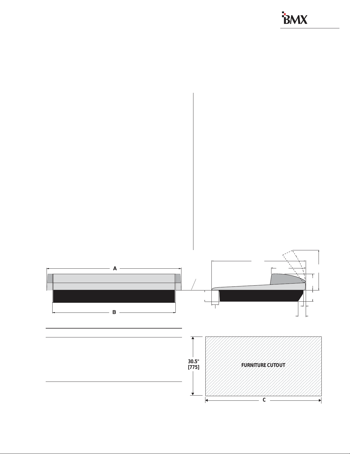
Installation
The BMX
a cutout (shown below) in the studio furniture
countertop. A minimum of 14 inches [356 mm] of
vertical clearance above the countertop is required
to fully open the meter panel. The rear 2.5 inches
[63.5 mm] of the mainframe bottom is open so
wiring can be easily dressed up through the main-
frame to the module connectors, which are hid-
den below the meter panel in normal use.
digital
mainframe “drops into”
2
The BMX
• The 8, 14, 22, 30 or 38 input frame with the
standard modules (Mic Preamp, Session, Control Room, three Outputs and DSP Cards) installed. Also installed are any optional items that
were also ordered (Universal Input, Telco/Codec and RLS modules, blank panels, Net Card).
• A 2RU rack-mount 48 volt power supply with
interconnecting cable.
• A BMX
MOD IV crimp tool and contact removal tool,
hex driver, and module removal tool).
• Audio and logic connector kit. T he kit contains
all the AMP MOD IV connector housings and
receptacle contacts typically needed for installation.
digital
console shipment consists of:
digital
Tool kit (3 AA batteries, AMP
Console, back view
Dimension T able
Mainframe A B C
BMXdigital-8 29.2" [742] 26.1" [663] 26.4" [671]
BMXdigital-14 42.0" [1067] 38.9" [988] 39.2" [996]
BMXdigital-22 54.8" [1392] 51.7" [1313] 52.0" [1321]
BMXdigital-30 67.6" [1717] 64.5" [1638] 64.8" [1646]
BMXdigital-38 80.4" [2042] 77.3" [1963] 77.6" [1971]
Millimeter dimensions in brackets. All dimensional tolerances are: +¼"
[6.4], -0" [0.0]. Typical setback from countertop edge to the front of the
console is 12" [305]. There must be 14" [356] of clearance above the
countertop to open up the meter panel.
33.4"
COUNTERTOP
4.00"
[102]
2.50"
[63.5]
[848]
11.8"
[300]
Console, side view, with dimensions
2345678901234567890123456789012123456
2345678901234567890123456789012123456
2345678901234567890123456789012123456
2345678901234567890123456789012123456
2345678901234567890123456789012123456
2345678901234567890123456789012123456
2345678901234567890123456789012123456
2345678901234567890123456789012123456
30.5"
[775]
HARRIS CORPORATION
2-1
Revision C • 1/04
2345678901234567890123456789012123456
2345678901234567890123456789012123456
2345678901234567890123456789012123456
2345678901234567890123456789012123456
2345678901234567890123456789012123456
2345678901234567890123456789012123456
2345678901234567890123456789012123456
2345678901234567890123456789012123456
2345678901234567890123456789012123456
2345678901234567890123456789012123456
FURNITURE CUTOUT
C
5.75"
[146]
4.00"
[102]
0.75"
[19]
2.50"
[63.5]
14.00
[356]
Page 14
digital
2 Installation
Console Installation
To simplify console installation, logic cable wir ing diagrams for specific peripheral equipment are
available from Harris Technical Support. Refer to
page 5-1 for contact information.
INST ALLATION NOTE: Do not locate the con-
sole near intense electromagnetic hum fields, such
as those produced by large power transformers
and by audio amplifiers that use inexpensive power
transformers operating in or near saturation.
Strong electromagnetic fields may impair the per -
digital
formance of the BMX
equipment. Route audio cables to achieve maximum practical distance from all AC power mains
wiring.
and neighboring
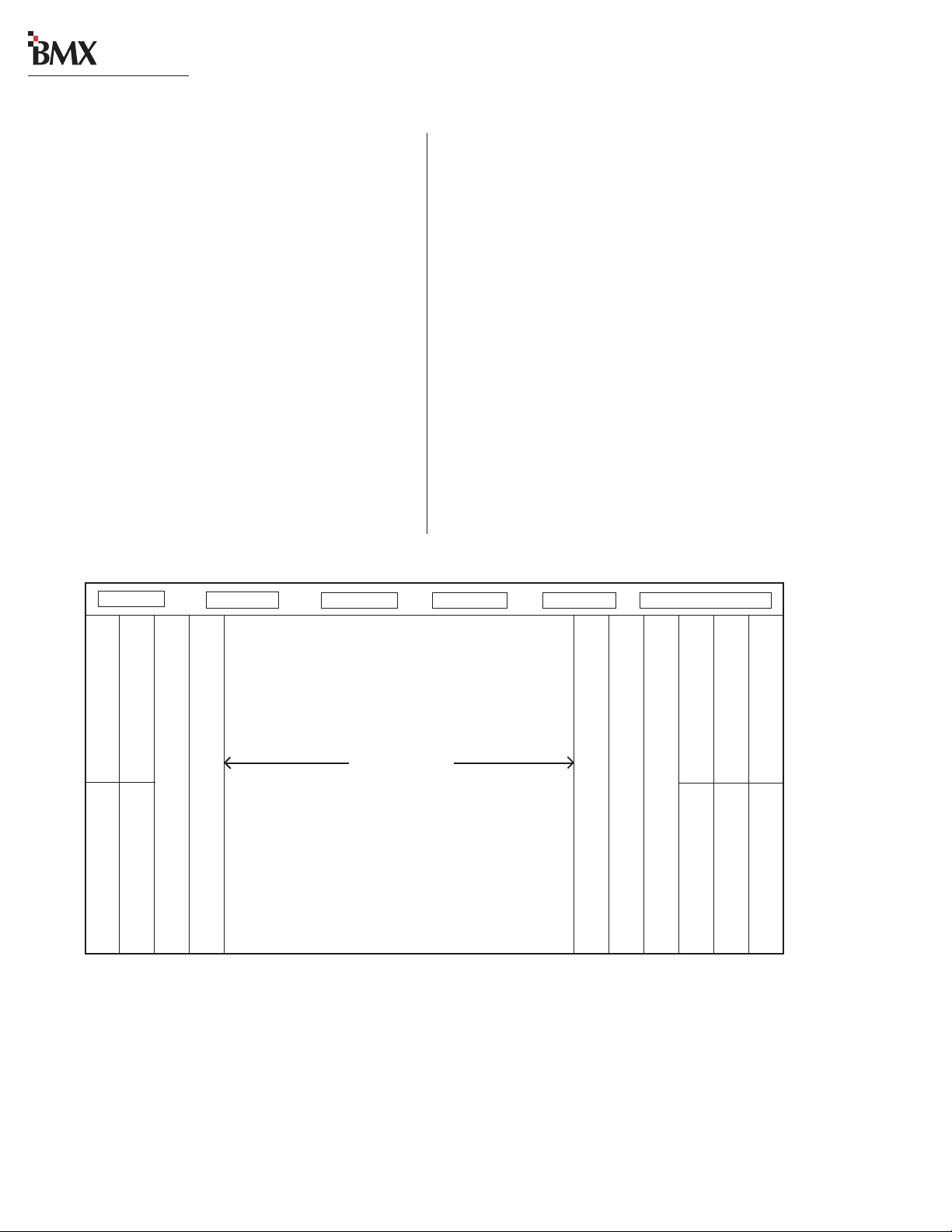
BMXdigital Mainframe, Module Configuration
MAINFRAME CONFIGURATION
The BMX
ules in the physical center of the mainframe. This
gives the operator equal reach to peripheral equipment located to either side of the console.
Module Placement
The 8, 14, 22, 30 or 38 input module positions
can have any combination or order of the following modules installed: Universal Input, Telco/
Codec (six maximum), and Remote Line Selector
(RLS). The remaining console positions are fixed.
The Microphone Preamp module(s), Session module, Control Room module, optional Studio module, and Output modules must be positioned as
shown below.
digital
design positions the input mod-
DSP Card 1 DSP Card 2* DSP Card 3* DSP Card 4* DSP Card 5* Net Card **
* The number of DSP Cards used is set by the frame size.
** The optional Net Card is used with the VistaMax Audio Management System.
*** These two slots are input module positions 1 and 2 on the BMXdigital-8 frame.
Output 1 (standard)
Output 2 (standard)
Mic Preamp (standard)
Mic Preamp 2 (optional)
12.5” blank panel (standard)
The input module positions are filled
with any combination or number of
Universal Input and Remote Line
Selector modules, and up to six Telco/
Codec modules. Unused positions are
Reserved position (covered by a 25" Blank panel) ***
Reserved position (covered by a 25" Blank panel) ***
12.25" Blank Panel (standard)
12.25" Blank Panel (standard)
NOTE:NOTE:
NOTE: The number of input module positions matches the console model number (e.g., BMXdigital-22 has 22 input positions). There is
NOTE:NOTE:
one DSP card in the BMXd-8, two DSP cards in the BMXd-14, three in the BMXd-22, four in the BMXd-30, and five in the BMXd-38.
The areas covered by the five 12.25" Blank Panels can be used for mounting Harris BMXdigital Accessory Panels or custom remote
control panels. Since the Harris BMXdigital Accessory Panels are 6" long, a PRE99-1100 Divider Kit (for mounting up to four Accessory
Panels in place of two 12.25" Blank Panels), or a PRE99-1101 Divider Kit (for mounting up to six Accessory Panels in place of three
12.25" Blank Panels) is required. Typically, the PRE99-1100 Divider Kit is installed in place of the Blank Panels on the left end of the
console and the PRE99-1101 is installed in place of the Blank Panels on the right end of the console. 6" Blank Panels (PRE99-1714-3)
cover unused Accessory Panel positions.
Input modules
Session (standard)
Control Room (standard)
covered with 25" Blank Panels.
Studio (optional) 25” blank panel (standard)
12.25" Blank Panel (standard)
Output 3 (standard)
12.25" Blank Panel (standard)
12.25" Blank Panel (standard)
2-2
HARRIS CORPORATION
Revision C • 1/04
Page 15
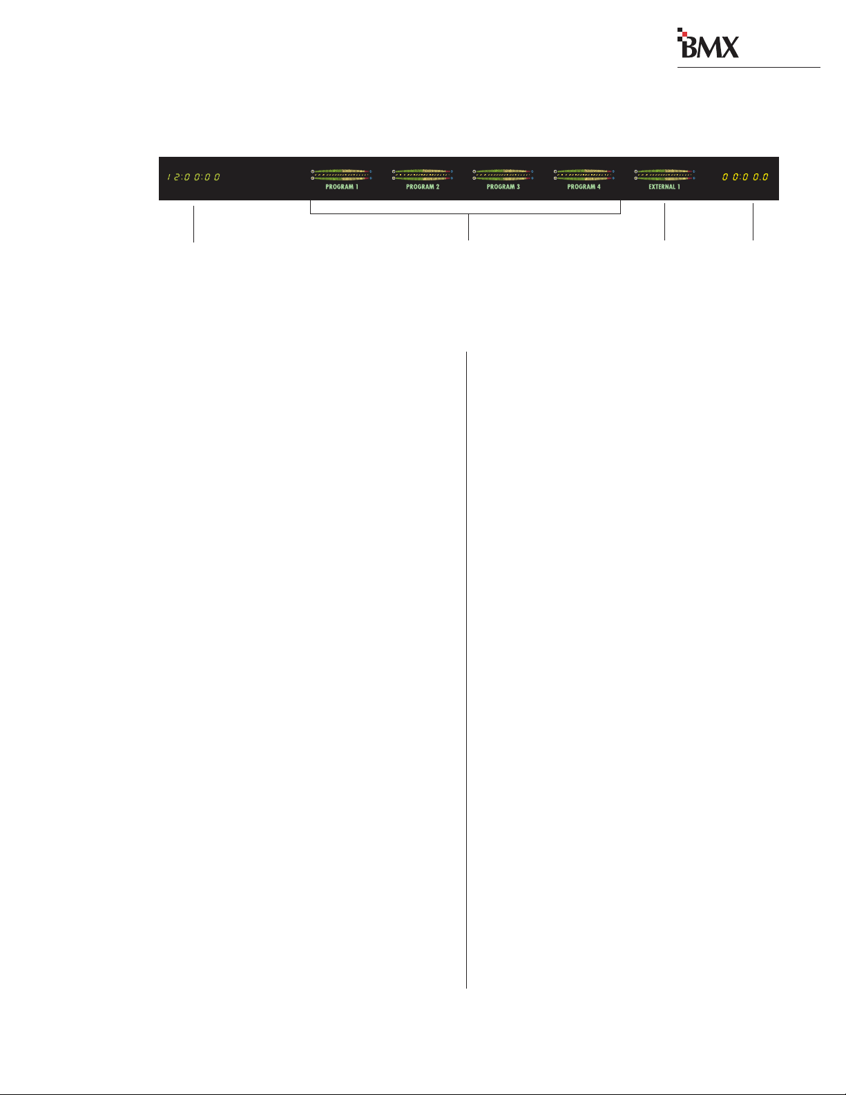
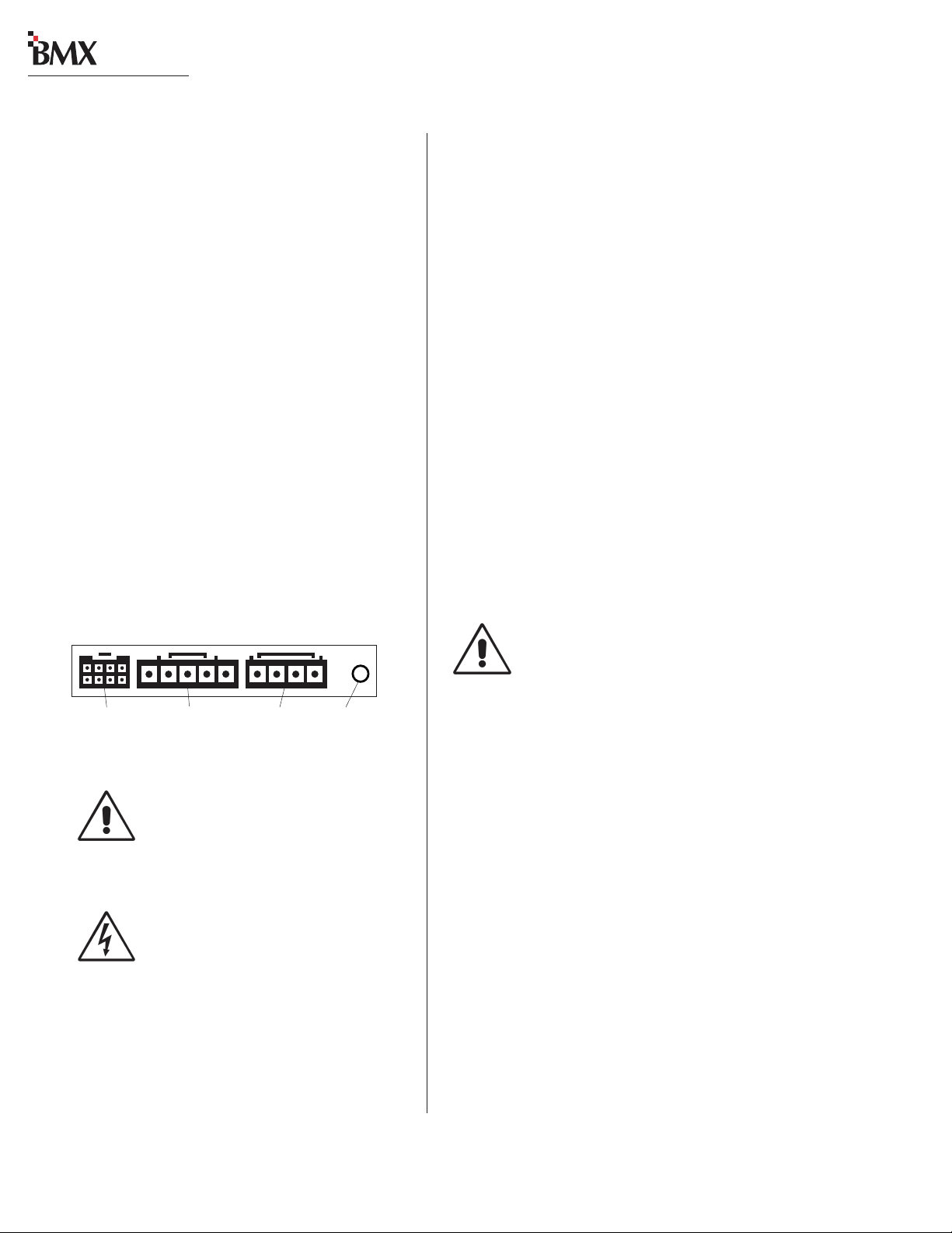
BMXdigital Meter Panel
digital
2 Installation
Clock
(not available on
the BMXdigital-14)
(BMXdigital-8 only has one meter)
Two Session module switches select
whether the Program or the Utility
Meter Panel
The meter panel has five horizontal Stereo Bar graph Meters, except for the BMX
has two meters. An alphanumeric display below
each meter identifies the current signal source
(PROGRAM 1, UTILITY 1, etc.).
Four of the meters provide simultaneous level
monitoring of the four Program or the four Utility
bus outputs, as selected by two Session module
buttons. On the BMX
module buttons cycle through the four Program
and the four Utility buses to select which bus to
display on the single main meter.
The right-hand meter (Auxiliary) shows the Cue
or Solo bus levels. When neither function is active, the meter shows a source selected on the Session module (from between the four external inputs, the two Sends, the four Utility buses or the
Telco Record output).
The meter display mode (peak hold or non-peak
hold) and the level where the peak indicators turn
on are set for each meter via DIP switches on each
meter display board.
On the left end of the meter panel is an ESEslaveable 12/24-hour digital clock (on all sizes
except for the BMX
there is an event timer that can be controlled
manually, through buttons on the Session module, or automatically, through module On reset
commands.
digital
digital
digital
-8, which
-8, these two Session
-14). On the right end
Main Meters
Buses are displayed
CONNECTOR ACCESS
panel, which is hinged on the rear of the mainframe. To access the connectors, open up the meter
panel by lifting up on the middle of the meter panel
while allowing it to pivot rearward to fully extend
the two gas springs.
way so that it does not accidentally fall shut.
be entirely removed from the mainframe:
of the hinges, then release the pins out of their
unlocked positions.
inserting a screw through the gas spring and the
bushing.
Auxiliary Meter
(Cue, Solo, or Session
module-switched source)
Module connectors are hidden below the meter
Event
Timer
Caution: Make sure the panel is open all the
To facilitate initial wiring, the meter panel can
1 Open up the meter panel fully and unplug
the meter power cable (attached to the rear
panel) and the three signal cables plugged into
the Session module.
2 With another person assisting to hold the
meter panel, remove the screw and bushing
that attach each gas spring to the meter panel.
Lay the gas springs on the mainframe while
working.
3 Unlatch the hinges by moving the release pins
to their unlocked positions and lift the meter
panel up and off the mainframe.
To reinstall the meter panel, align the two halves
Reattach each gas spring to the meter panel by
2-3
HARRIS CORPORATION
Revision C • 1/04
Page 16
digital
2 Installation
POWER SUPPLY
The 99-1205 power supply requires 2 RU of
rack space within the console cabinetry , below and
to the left or right of the supporting countertop.
The 48 Volt Power Supply must be installed so
that the 30 foot power supply cable (90-1709) is
not under any tension when routed through the
cabinet and connected to the mainframe’s rear
panel connectors.
Connecting the Power Supply
The power supply cable has two connectors:
• A 5-pin connector to supply 48 volt DC
power to the console.
• A 4-pin connector to supply power status
information (Imminent Power Loss) to the
console.
Both connectors must be attached to the back
digital
of the BMX
and to the power supply.
GROUNDING AND SHIELDING
The broadcast facility’ s technical ground can be
connected to the mainframe chassis using the
threaded insert on the rear of the console (shown
in the Power Connections drawing on this page).
Use a 10-32 screw and crimp lug to terminate the
facility’s technical ground wire.
Connect the cable shields at both the console
and the peripheral end when all system components share a common ground potential and are
using isolated ground A C outlets tied individually
back to the main technical ground.
If isolated ground A C outlets are not available,
connect the cable shields at the console end only.
The shields should be floated (left unconnected)
at the peripheral device end. Ensure the peripheral devices connect to a clean ground through
their power cords, or through separate ground
wires to the facility’s technical ground.
Power Connections —
Console Mainframe, Rear Panel
Meter Panel
Power
48 VDC
Power
Power Supply
Status
DC GROUNDING NOTE:
connect
ground wiring to the chassis of the
power supply .
the audio or logic supply
AC GROUNDING NOTE: Do not
defeat the safety ground in any way.
Doing so may provide a potentially
dangerous condition to the operator.
Threaded
Insert for
10-32 screw
Do not
Redundant Power Supply
To provide redundant console power, two
99-1205 power supplies can be connected to the
console through a 99-1203 48 Volt Coupler.
POWER SUPPLY GROUNDING NOTE:
The P ower Supply chassis connects to the
AC mains safety or “U” ground wire.
AUDIO GROUND NOISES: Buzz pickup is gener -
ally electrostatic—such as capacitive coupling
between an audio line and a power line. To avoid
audio ground noises, do not route audio lines in
the same wireway as an AC power line.
INSTALLING BACKUP BATTERIES
Three AA rechargeable NiCad batteries are supplied in the 76-2001 Tool Kit. They should NOT
be installed until the console is completely installed
and is ready for everyday use.
The batteries supply a “K eep Alive” voltage that
holds each module’s logic state during momentary power outages. They mount in a battery clip
located below the three 12.25" blank panels on
the right end of the console.
2-4
HARRIS CORPORATION
Revision D.1 • 12/10
Page 17
digital
2 Installation
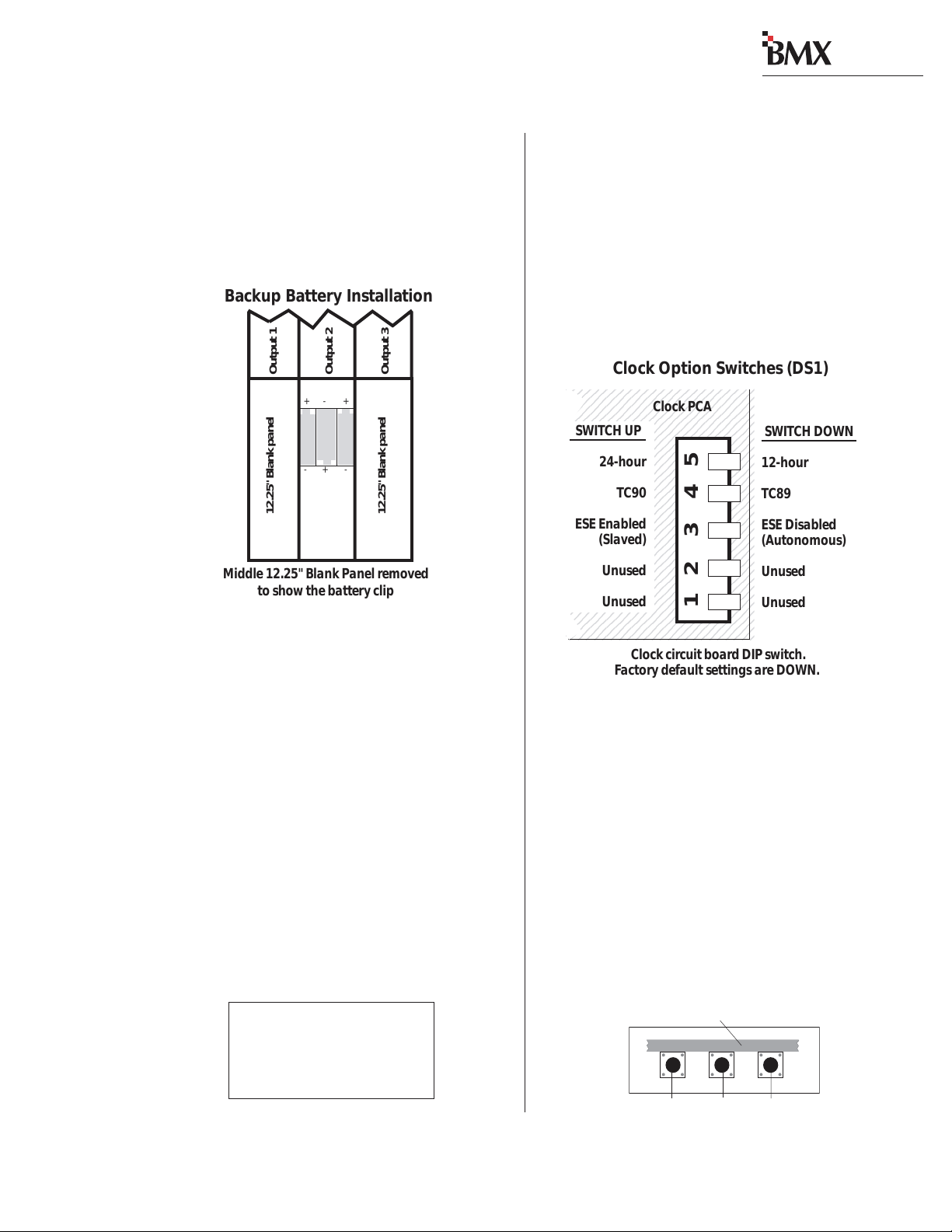
To install the backup batteries:
1 Remove the blank panels in front of the Out-
put modules using the supplied hex driver.
2 Install the batteries into the battery clip,
observing the correct polarity as marked on
the battery clip and shown below.
Backup Battery Installation
Output 1
12.25" Blank panel
Middle 12.25" Blank Panel removed
to show the battery clip
Note: Replace the batteries yearly to ensure con-
tinuous backup protection. Use only P anasonic P50AAH or equivalent batteries designed for continuous slow charge operation. To prolong battery
life, remov e the batteries when the console is powered down for an extended period.
Output 2
+- +
-+-
Output 3
12.25" Blank panel
SETTING THE CL OCK
The digital time-of-day clock (not available on
digital
the BMX
or slave modes. W hen used autonomously (the factory preset), a temperature-controlled quartz crystal oscillator controls the clock timing. In slave
mode, clock timing comes from a TC89- or TC90compatible ESE master clock reference signal.
-14) can operate in autonomous
Master clocks are available from:
ESE
142 Sierra St.
El Segundo, CA 90245.
Telephone: 310.322.2136
www.ese-web.com
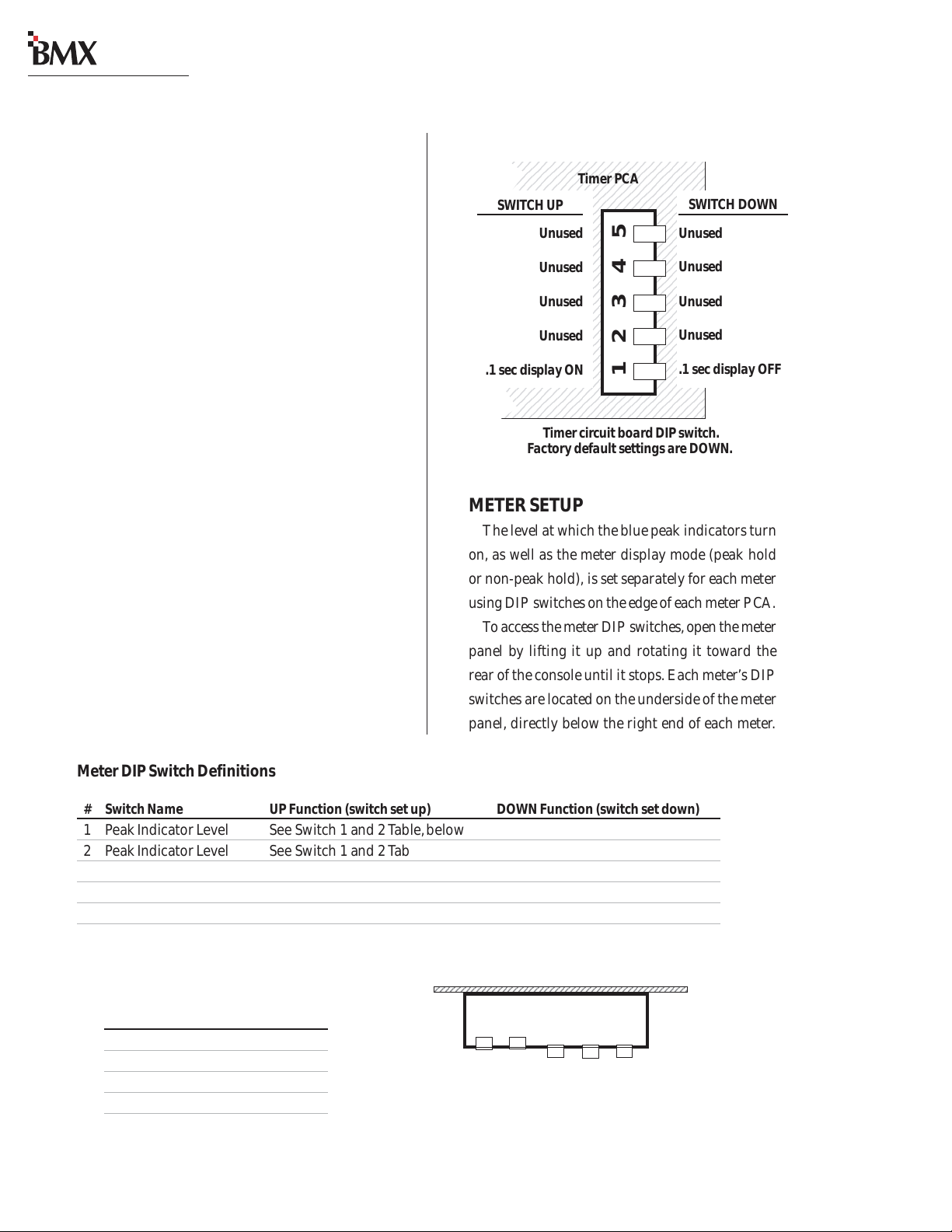
The operating mode (autonomous or ESE sla ve),
the type of ESE signal (TC89 or TC90), and the
type of clock time desired (12-hour or 24-hour
format) are set using DIP switch DS1 on the clock
PCA. DS1 is on the right rear edge of the circuit
board.
To access the clock PCA, open the meter panel.
The clock PCA is mounted behind the clock display on the meter panel.
Clock Option Switches (DS1)
12345678901234567890123
2345678901234567890123
1
1
2345678901234567890123
2345678901234567890123
1
1
2345678901234567890123
2345678901234567890123
1
2345678901234567890123
1
SWITCH UP
1
2345678901234567890123
12345678901234567890123
12345678901234567890123
24-hour
12345678901234567890123
2345678901234567890123
1
1
2345678901234567890123
12345678901234567890123
2345678901234567890123
1
12345678901234567890123
2345678901234567890123
1
1
2345678901234567890123
ESE Enabled
12345678901234567890123
12345678901234567890123
(Slaved)
12345678901234567890123
12345678901234567890123
2345678901234567890123
1
12345678901234567890123
Unused
12345678901234567890123
12345678901234567890123
12345678901234567890123
Unused
12345678901234567890123
12345678901234567890123
12345678901234567890123
12345678901234567890123
TC90
Clock PCA
12345
SWITCH DOWN
12-hour
TC89
ESE Disabled
(Autonomous)
Unused
Unused
Clock circuit board DIP switch.
Factory default settings are DOWN.
With the clock set to autonomous mode, it must
be set after power-up. There are three clock set
buttons on the bottom left front of the clock PCA.
• Use the right button (F ast) to scroll by minutes at a time.
• Use the middle button (Slow) to scroll by
seconds at a time.
• Use the left button (Hold) to synchronize
the console clock to an external time refer ence by setting the clock ahead of the external time reference, then press and hold
Setting the Clock
Clock Circuit Board, lower left front edge
Hold Slow Fast
2-5
HARRIS CORPORATION
Revision D.1 • 12/10
Page 18
digital
6
6
6
6
6
6
6
6
6
6
6
6
6
6
6
6
6
6
6
6
6
6
6
6
6
6
6
6
6
6
1234567890123456789012345678901212345678901234567
1234567890123456789012345678901212345678901234567
2 Installation
the HOLD button to freeze the time. When
the external time reference reaches the time
digital
on the BMX
clock, release the HOLD
button to start the clock.
When an ESE time-code signal is connected to
the BNC connector on the clock circuit board, and
slave mode is selected (DS1-3 is set UP), the clock
does not require setting. If the ESE time-code signal fails, the clock automatically defaults to its internal crystal reference oscillator , flashing the display colons to indicate the loss of time-code.
EVENT TIMER
The event timer displays time in minutes, seconds and tenths of seconds. The only timer option
setting is whether to display the tenths of seconds
digit as the timer runs. DS1-1 (a DIP switch on
the timer circuit board, located behind the timer
display), sets whether the tenths are shown or not.
In the UP position, the tenths of seconds are displayed. In the DOWN position, the factory default,
the tenths do not display while the timer runs.
Note that the tenths of seconds are always shown
when the timer is in the Stop or Hold mode.
Event Timer Option Switches (DS1)
234567890123456789012345
234567890123456789012345
234567890123456789012345
234567890123456789012345
234567890123456789012345
234567890123456789012345
SWITCH UP
234567890123456789012345
234567890123456789012345
234567890123456789012345
234567890123456789012345
234567890123456789012345
234567890123456789012345
234567890123456789012345
234567890123456789012345
234567890123456789012345
234567890123456789012345
234567890123456789012345
234567890123456789012345
234567890123456789012345
234567890123456789012345
234567890123456789012345
234567890123456789012345
234567890123456789012345
234567890123456789012345
234567890123456789012345
234567890123456789012345
.1 sec display ON
234567890123456789012345
234567890123456789012345
234567890123456789012345
234567890123456789012345
Unused
Unused
Unused
Unused
Timer PCA
12345
SWITCH DOWN
Unused
Unused
Unused
Unused
.1 sec display OFF
Timer circuit board DIP switch.
Factory default settings are DOWN.
METER SETUP
The level at which the blue peak indicators turn
on, as well as the meter display mode (peak hold
or non-peak hold), is set separately for each meter
using DIP switches on the edge of each meter PCA.
To access the meter DIP switches, open the meter
panel by lifting it up and rotating it toward the
rear of the console until it stops. Each meter ’s DIP
switches are located on the underside of the meter
panel, directly below the right end of each meter.
Meter DIP Switch Definitions
# Switch Name UP Function (switch set up) DOWN Function (switch set down)
1 Peak Indicator Level See Switch 1 and 2 Table, below
2 Peak Indicator Level See Switch 1 and 2 Table, below
3 Meter Display Mode * Non-peak hold Peak hold
4 Spare Switch
5 Termination Switch Set UP for Me ter 1 Set DOWN for Meters 2 - 5
* Active only when meters are set to display Average and Peak (Session module DIP switch 1 set to Off)
Switch 1 and 2 Table
Use these switches to set the level
where the Blue peak indicators light.
#1 # 2 Peak Level
DOWN DOWN 0 dB
UP DO W N -2 dB
DOWN UP -4 dB
UP UP -6 dB
Meter Option Switches (DSW2)
Switches 1, 2, 3 shown down,
switches 4 and 5 shown up.
2-6
HARRIS CORPORATION
Revision C • 1/04
123 45
Meter PCA
Page 19
digital
2 Installation
Cabling and Wiring
Before installing the console, dra w up a facility
wiring plan that lists the console interconnections
with all peripheral devices. Identify and create tags
for all audio and logic cabling. List each connection in a master facility wiring logbook to facilitate wiring installation, future system wiring
changes, equipment updates , and system troubleshooting.
Refer to the module Quick Connection Guides,
on pages 2-16 to 2-57, for information on each
audio and logic connection (including block diagrams for each logic interface connector) and on
each module’s setup DIP switches.
REQUIRED CABLES AND WIRE
The BMX
cables and wires:
digital
uses the following types of
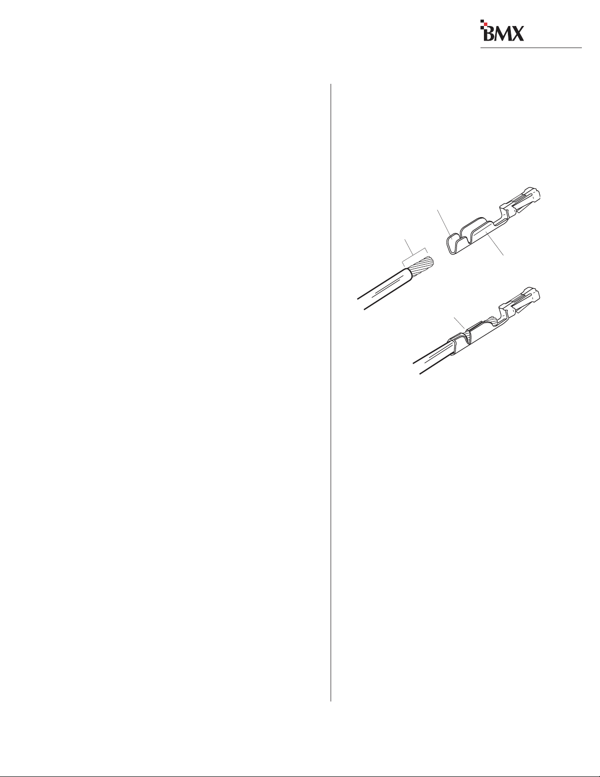
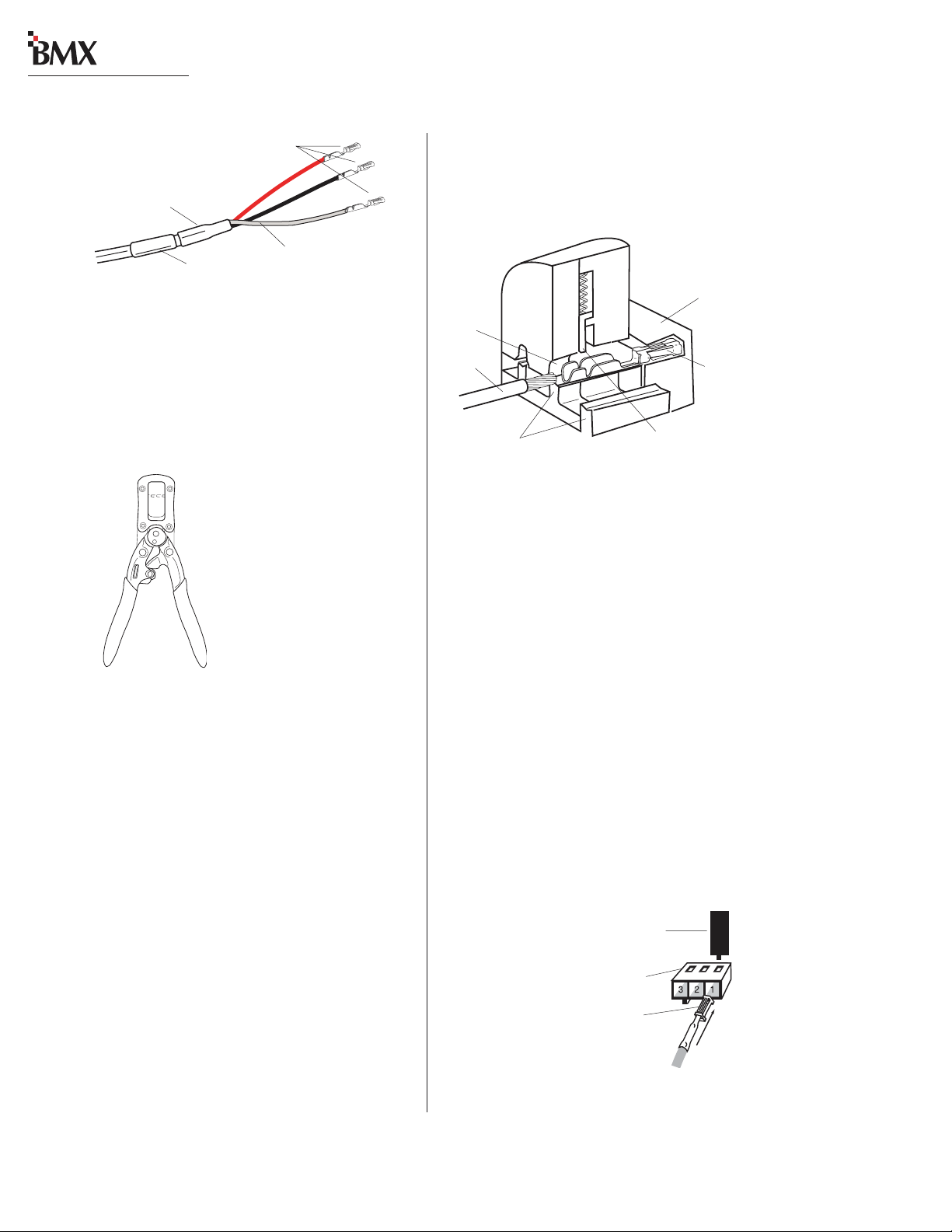
WIRE PREPARATION
All BMX
nates in AMP MOD IV receptacle contacts at the
console. Stranded wire of 22 to 26 AWG, with insulation diameters of .040 to .060 inch, can be
used with the AMP MOD IV receptacle contacts.
9/64” [3.57 mm]
digital
audio and logic wiring termi-
Insulation Barrel
Properly
Crimped Contact
Wire Barrel
• Analog audio connections require twoconductor, stranded, insulated, foil-shield
cable using a separate shield drain wire
(equivalent to Belden 8451, 9451 or 8761).
• AES/EBU connections require 110 ohm
two-conductor, stranded, insulated, foilshield cable containing a separate shield
drain wire (equivalent to Belden 1800A).
• Logic control cables require stranded, 22
AWG, multiple-conductor, non-shielded,
jacketed cable (equivalent to Belden 9423,
8457 or 9421). The number of conductors
used is determined by the application. Typically cables with five and eight wires are
most often used for constructing logic
cables. Ev en though there are eighteen distinct signals on the Logic Interface connector, only a handful are typically used for
any given application.
AMP MOD IV Receptacle Contacts
Follow these steps for audio wire preparation:
1 Strip the cable insulation jacket and foil shield
back 1½" [38.10 mm].
2 Remove the foil shield and sleeve the drain
wire with 20 AWG Teflon sleeving. Leave
9/64" [3.57 mm] of the drain wire exposed.
3 Cover the cut end of the jacket with 3/4"
[19.05 mm] of heat-shrink tubing. Shrink this
tubing, centered on the jacket cut end, to hold
the drain wire sleeving in place.
4 Strip the signal wire insulation back 9/64"
[3.57 mm].
5 Crimp the receptacle contact onto the wire
and insulation.
AA
udio Cudio C
able Sable S
A
udio C
AA
udio Cudio C
mended grounding procedures, the drain wires
must be sleeved with Teflon sleeving and heat
shrink tubing must cover all cable jacket cut ends
to insulate the shield wiring.
able S
able Sable S
hielding Nhielding N
hielding N
hielding Nhielding N
otot
e:e:
ot
e: T o follow recom-
otot
e:e:
2-7
HARRIS CORPORATION
Revision C • 1/04
Page 20
digital
2 Installation
AMP MOD IV
Receptacle Contacts
3/4” [19.05 mm]
Shrink Tubing
Teflon Sleeving
Cable ID Tag
over drain w ire
Audio Wire, ready for insertion into an
AMP MOD IV connector housing
Logic control cables are fabricated in a similar
manner to the audio wiring. Strip the jacket insulation back 1½" [38.10 mm], sleeve the cut end
with 3/4" [19.05 mm] of shrink tubing and strip
the insulation from each wire 9/64" [3.57 mm].
AMP MOD IV
Contact
Crimp T ool
CRIMP TOOL OPERA TION
A ratcheting AMP crimp tool with contact holder
is included. The tool crimps both the insulation and
wire barrels on the AMP MOD IV receptacle contact in one crimp. To use the ratcheting crimp tool:
1 Insert the contact into the contact holder with
the barrel openings up. Typically the middle
holder is used (for 20 - 24 AWG wire). Flip
the holder up so it magnetically latches against
the crimp tool. The end of the insulation barrel will be about 2 mm from the end of the
die. Close the tool one click (only until the
anvil holds the contact in place, as shown in
the cutaway view, above.)
2 Insert the prepped wire into the contact until
the insulation hits the tool’s wire stop. Hold
the wire in place while squeezing the tool
handles to crimp the contact onto the wire.
The tool handles automatically release and
spring open after the crimp cycle is complete.
Contact Holder,
snapped against
Crimp Tool
AMP MOD IV
Receptacle
Contact
Die
Wire
Printed
Anvils
Side of
Crimp
Tool
Insulation Stop
Crimp Tool — Cutaway View
Once the contact has been crimped, insert and
lock the contact receptacle into the appropriate
connector housing following the pinout diagrams
found in the Quick Connection Guides on pages
2-16 to 2-57.
A receptacle contact is inserted into the housing with its locking tab side toward the locking
tab slots on the side of the connector housing. A
slight click can be heard when the contact’s locking tab springs up into the locking tab slot.
To remove a contact from a housing , the PRE70129 Contact Removal Tool (included in the
PRE76-2001 tool kit) is required. Insert the tool's
tip into the locking tab slot and press the locking
tab down while lightly pulling on the wire to remove the contact from the housing.
Contact Removal Tool
Locking Tab Slots
Locking Tab
Receptacle Contact,
Insertion & Removal Detail
2-8
HARRIS CORPORATION
Revision C • 1/04
Page 21
digital
2 Installation
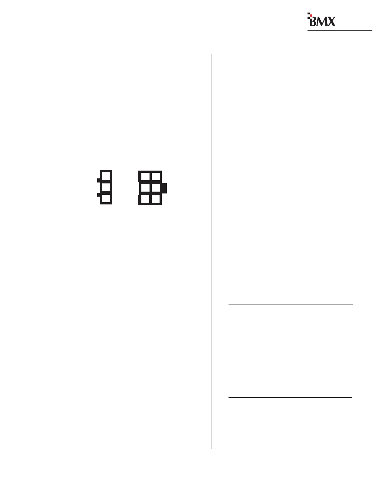
AUDIO CONNECTIONS
Audio connections take advantage of the threepins per row design of the three- and six-pin AMP
MOD IV housings. Three-pin housings are used
for balanced digital connections while six-pin
housings are used for balanced analog connections.
One important exception is the Mic Preamp module, which uses three-pin connectors for balanced
analog microphone inputs.
Pin Numbers for Analog &
Digital Audio Connectors,
3
2
1
3-pin
connector
Pin numbering shown from the wire insertion end,
oriented from the board operator’s perspective.
All audio wiring, when plugged into a module
connector, has this orientation:
• The audio shields are on pins 1 and 4 (the
pins closest to the board operator).
• The audio low wires (typically the black
wires) are on pins 2 and 5 (the middle pins).
• The audio high wires (typically the red
wires) are on pins 3 and 6 (the back pins).
For stereo applications, the left channel wires
plug into the left column of pins and the right channel wires plug into the right column of pins (from
the board operator’s perspective).
When a six-pin input comes from a mono source
(such as an external microphone preamp output),
the left and right inputs should be paralleled together (pins 1 and 4 tied together, pins 2 and 5
tied together and pins 3 and 6 tied together). If
this is not done, then the module’s mode buttons
will have to be set for mono operation (see page 35 for L/R Mode information on the Universal Input Module).
3
6
2
5
1
4
6-pin
connector
Analog Connections
There are no analog interstage patch points
within the BMX
digital
input or output modules.
To use the console with a patch bay, connect the
line level outputs from the peripheral devices directly to the patch bay. Normal these signals to
the appropriate analog input modules.
digital
Likewise, the BMX
’s analog outputs may
be routed through a patch bay normalled to standard peripherals such as analog on-air processing
gear , recorders, telephone hybrids, etc.
The Mic Preamp module’ s line-level outputs (+4
dBu, nominal, balanced, mono outputs) can also
be routed through a patch bay normalled to an
input module, or to external mic processing .
When a mic processor with only a microphone
level input is used, the microphone is connected
directly to the mic processor , with the processor ’s
line-level output either directly connected to an
input module (using the mono wiring pinout
shown below) or through a patch bay normalled
to an input module.
Two-Channel (Ster e o)
Line Input or Output — 6-Pin Housing
Pin Signal Description
1 Shield for the left channel, or signal 1
2 Low (- input or output), left channel, or signal 1
3 High (+ input or output), left channel, or signal 1
4 Shield for the right channel, or signal 2
5 Low (- input or output), right channel, or signal 2
6 High (+ input or output), right channel, or signal 2
Single Channel (Mono)
Line Input — 6-Pin Connector
Pin Signal Description
1 Shield (connects directly to the chassis)
2 Low (- input) tied to pin 5
3 High (+ input) tied to pin 6
4 Shield (connects directly to the chassis)
5 Low (- input) from pin 2
6 High (+ input) from pin 3
2-9
HARRIS CORPORATION
Revision C • 1/04
Page 22
digital
2 Installation
Microphone Input — 3-Pin Connector
Pin Signal Description
1 Shield (connects directly to the chassis)
2 Low (- input)
3 High (+ input)
Digital Connections
Digital inputs and outputs are wired like the
Microphone Input shown above.
The Universal Input, RLS and Telco/Codec modules have digital inputs. The three-pin digital inputs accept AES-3 (AES/EBU) compatible signals,
and as mentioned in the Unbalanced Connections
section that follows, can also accept
S/PDIF signals in most cases.
Each Output module has multiple digital outputs. Each outputs an AES-3 compatible signal.
Note: The digital outputs cannot connect directly to an S/PDIF input. A signal translation
interface is required.
AES/EBU Digital Inputs and
External Clock Reference Input
Pin Signal Description
1 Shield (connects directly to the chassis)
2 Low (- input)
3 High (+ input)
AES/EBU Digital Outputs
Pin Signal Description
1 Shield for AES/EBU signal
2 Low (- output)
3 High (+ output)
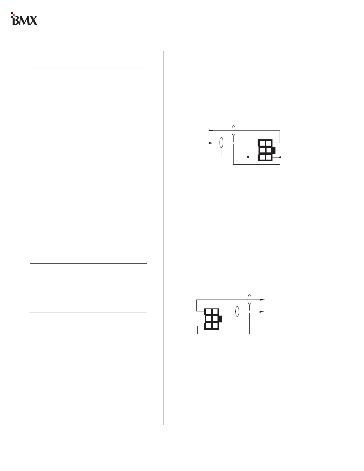
If a match box is not available, connect an un-
digital
balanced device to a BMX
input using the
following illustration.
Connecting an Unbalanced Device
to a BMXdigital Analog Input
From the
Unbalanced
Device
R
L
Shields
Console
Balanced
Input
6
3
5
2
4
1
When an unbalanced device must be connected
digital
to a BMX
balanced analog output, and an
IHF-PRO match box is not available, do not tie
the low (-) and shield pins together to “unbalance”
the signal. The low output pin must always be left
digital
“floating” when unbalancing a BMX
out-
put, as shown in the following illustration.
Connecting an Unbalanced Device
to a BMXdigital Analog Output
(Nominal Output is -2 dBu)
Console
Balanced
Output
3
6
2
5
1
4
(Make no connections to pins 2 & 5)
To the
Unbalanced
Device
L
R
Shields
UNBALANCED CONNECTIONS
Although all analog inputs and outputs are
active and balanced, unbalanced consumer or
“semipro” equipment can be connected to the console. For best results, connect an unbalanced device through an IHF-PRO match box and keep
the unbalanced cable lengths as short as possible.
HARRIS CORPORATION
2-10
Revision C • 1/04
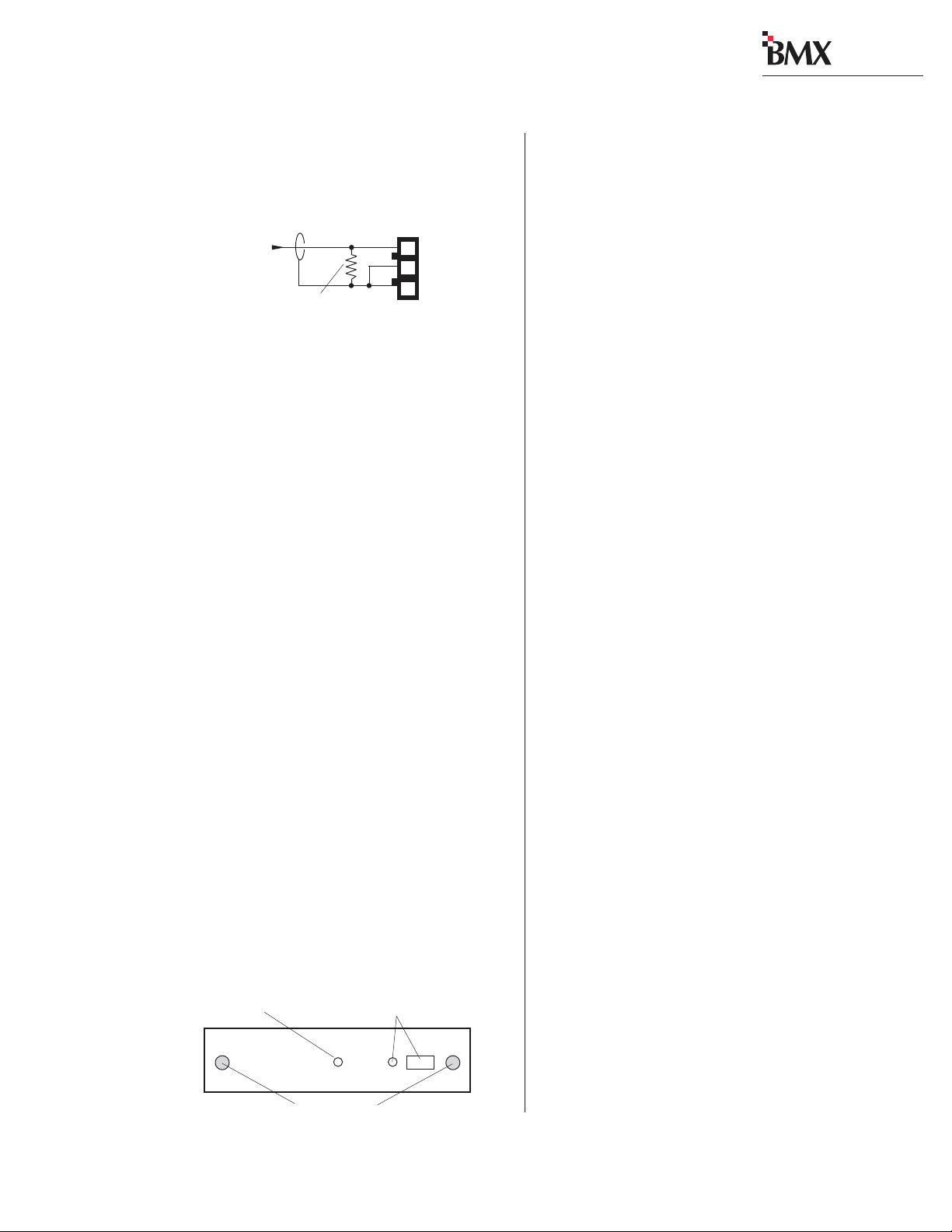
S/PDIF Signals
Digital devices with only an S/PDIF digital output can connect to a BMX
when a 249 ohm resistor is used to load the 75
ohm S/PDIF cable. Install the resistor at the AMP
MOD IV housing per the illustration on the next
page.
digital
input, but only
Page 23
digital
2 Installation
Connecting an S/PDIF Device to
a BMXdigital AES/EBU Input
From
S/PDIF
Device
Signal
Shield
249 ohm resistor
Console
AES/EBU
Input
3
2
1
An unbalanced-to-balanced line transformer can
also be used to interface an S/PDIF signal.
Note 1: A signal conversion interface must be
used to connect an AES/EBU output to a S/PDIF
input.
Note 2: Some S/PDIF signals may not work with
digital
the BMX
’s inputs, even with the additional
load resistor or a transformer , because of nonstandard levels or protocols in the S/PDIF product.
DIGITAL CLOCK REFERENCE
The BMX
rate timing, with sample rate converters on each
input to synchronize/convert external digital signals to the console’s internal 48 kHz sample rate.
The console can synchronize to an external AES3 digital reference signal (of 48 kHz, ±100 ppm
only) when using the optional Ext. Input DSP card
(99-1356-1). A 3-pin connector on the card has a
green LED next to it to indicate whether the internal or external reference is active. When a valid
external reference signal is present, the LED is
off. If the LED is still lit with an external signal
connected, it indicates the reference signal is not
present or is out of range.
Heartbeat LED —
Flashes to indicate the
DSP is good.
digital
has an internal clock for sample
DSP Card Features
External Input and LED —When
unlit, indicates the console is
using the External reference.
(optional connection)
Thumbscrews
LOGIC CONNECTIONS
BMX
digital
modules have built-in logic I/O interfaces that can control, or be controlled by,
peripheral devices connected to the console. For
example, a CD player connected to a module can
be automatically started when the module is
turned on. Then, at the end of the cut, the CD
Player logic can turn the module audio off and
control the off button illumination to indicate that
the cut has been played.
When a mic remote control panel is connected,
its On, Off, Cough and Talkback buttons control
the module while tally outputs from the module
control the button tallies on the mic panel.
digital
BMX
connectors:
• Universal Input modules have two MAIN
connectors for the devices connected to the
A and the B inputs and two T/B OPTION
connectors for separate talkback control for
the A and B mic inputs.
• Telco/Codec and RLS modules have a
single LOGIC I/O connector for the device
connected to the module.
• The Session module has three EXT TIMER
connectors for resetting studio or producer
timers, a D AT A (RJ-45) connector for connecting the console to a local LAN and the
connectors for the factory-installed wiring
that ties the mainframe to the meter panel.
• The Control Room module has a LOGIC
connector for the warning light, mute, dim,
and talkback. A CUE CNTL connector allows external cue input control.
• The optional Studio module has two
LOGIC connectors for dim, mute, and warning indications and two talkback connectors (PRODUCER and EXTERNAL).
• The Output 1 module has a PRODUCER
IFB LOGIC connector.
modules have the following logic
2-11
HARRIS CORPORATION
Revision C • 1/04
Page 24

digital
2 Installation
MODULE QUICK GUIDES
Pages 2-16 to 2-57 have Quick Guides to configuring logic connections and DIP switch settings.
Each guide covers the audio and logic connector
pinouts and signal descriptions, DIP switch setting definitions, and, for some modules, logic block
diagrams. The Module Quick Guides:
• Mic Preamp: pages 2-16 & 2-17
• Universal Input: pages 2-18 to 2-23
• Telco/Codec: pages 2-24 to 2-27
• RLS: pages 2-28 to 2-31
• Session: pages 2-32 & 2-33
• Control Room: pages 2-34 to 2-38
• Studio: pages 2-40 to 2-49
• Output 1: pages 2-50 to 2-53
• Output 2: pages 2-54 & 2-55
• Output 3: pages 2-56 & 2-57
Note: T here are four versions of each Input module: full-featured (shown in the Quick Guides); limited-function modules (without the Utility or Send
bus controls); and full-featured or limited-featured
Net-only modules (which have no input and logic
connectors).
Pages 2-58 to 2-63 show examples of typical
logic connections to the Universal Input module
from a mic remote control panel, a CD pla yer and
a digital delivery system. Pages 2-64 thru 2-66
cover the Net Card and Net-Only modules.
Note: F or complete isolation of the console and
a peripheral device, use only the opto-isolated control connections. Both logic ground and +5 VDC
are referenced to the console’s power supply and
ground and should only be connected to isolated
devices like mic control panels or other Harris Accessory Panels. Connecting logic ground to a nonisolated device may result in a ground loop between the console and the peripheral device.
HARRIS CORPORATION
UNIVERSAL LOGIC INTERFACE
A block diagram of the Universal Input module
logic interface is shown on page 2-13. Logic outputs (shown on the right side of the illustration)
are isolated from the peripheral device by six solidstate “relays. ” T he “relay contacts” can switch logic
voltages of up to 60 volts at 350 mA.
Pressing the On button generates a 220 ms contact closure from pin 5 (Start Command Pulse). A
sustained contact closure while On is available on
pin 23 (Start Command Sustained). It stays closed
as long as the module is On. Pressing the Off button generates a 220 ms closure from pin 4 (Stop
Command Pulse). These three command outputs
are tied together at pin 13 (Command Common).
Module DIP switches DS2-2 (for the A input)
and DS4-2 (for the B input) , set whether a single
pulse is output when the module status changes
(Off to On, or On to Off), or if each additional press
of the On or Off buttons produces another contact
closure. The default setting (switch 2 set to OFF)
is a single contact closure. When DS2-2 or DS4-2
is set to ON, then each additional press of the On
or Off button produces another 220 ms contact
closure.
T he remaining outputs; Logic Active/Cue Tally
[pin 15], On Tally [pin 17], and Off Tally [pin 16],
are tied together at Tallies Common [pin 14]. T hey
present sustained logic outputs for each function.
There are six logic inputs on the left side of the
illustration: Reset, Ready, On, Off, Cough and Talk
to Control Room/Ext. Cue. These inputs are optoisolated and current limited so any logic voltage
from +5 to +40 VDC can be used. Reset and Read y
have both high (+) and low (-) input pins so that
either polarity logic can be used. The other inputs
use active low logic (pull to ground) that typically
come from a mic control panel (although On and
Off could be triggered by a peripheral device). To
use these inputs, pin 18 (Activate Logic Inputs)
must be jumpered to the + logic voltage. Typically
2-12
Revision C • 1/04
Page 25
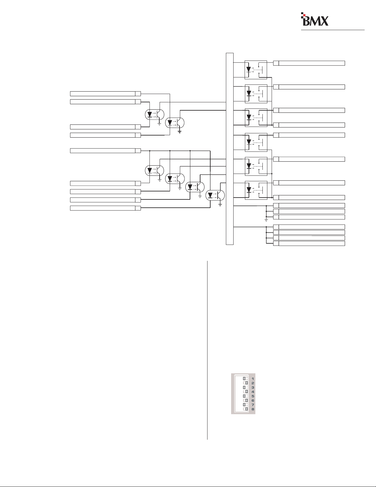
digital
2 Installation
Block Diagram, Universal Input
Module Logic Inter f ace
Reset Input (+)
Ready Input (+)
Ready Input (-)
Reset Input (-)
Activate Logic Inputs(+)
On Input (-)
Off Input (-)
Cough Input (-)
MIC: Talk To C/R (-) LINE: Cue Input (-)
22
24
21
19
18
7
8
9
20
Notes:
Opto-Isolator inputs can handle +5 to +40 VDC logic
Opto-Isolator outputs can handle up to 60 volts or 350 mA
Internal Logic
+5 volts
Start Command Pulse
5
Stop Command Pulse
4
Start Command Sustained
23
Commands Common
13
MIC: Logic Active Tally LINE: Cue Tally
15
On T ally
17
Off T ally
16
Tallies Common
14
Logic Ground
1
Logic Ground
2
Logic Ground
3
Logic Supply +5VDC
6
Logic Supply +5VDC
10
Logic Supply +5VDC
11
Logic Supply +5VDC
12
this is pin 6 (Logic Supply +5 VDC), but it can
also be supplied by the peripheral device.
The Audio Reset and Ready inputs can use either active low logic (pull to ground) or active high
logic (pull to +VDC) from peripheral devices. With
active high logic, Ready (-) and Audio Reset (-)
are tied to logic ground on the peripheral device.
Ready (+) and Audio Reset (+) then connect to
the appropriate logic outputs on the peripheral
device.
When active low logic is used by the peripheral
device, Read y (+) and A udio Reset (+) connect to
the logic supply voltage on the peripheral device,
and Ready (-) and Audio Reset (-) connect to the
appropriate logic outputs.
Pin 15’s signal (Logic Active Tally / CueTally)
changes depending upon whether the channel logic
switches (DS1/DS3) are set to mute any location.
When any mute is set (DS1/DS3, switches 2 - 5
are set to On), the module is set as a microphone
and the Logic Active Tally output (pin 15) is closed
when that input (input A for DS1 or input B for
DS3) is active. When no mute is set, the module is
set for line logic and pin 15 becomes a Cue Tally.
Setting DIP Switches
When referring to a module’s DIP switch setting, a switch is Set to Off when it is to the right
and it is Set to On when it is to the left (orientation is from the board operator’s perspective). In
the illustration, all odd numbered switches are shown set
to On and all even numbered
switches are shown set to Off.
On = set Left
Off = set Right
2-13
HARRIS CORPORATION
Revision C • 1/04
Page 26
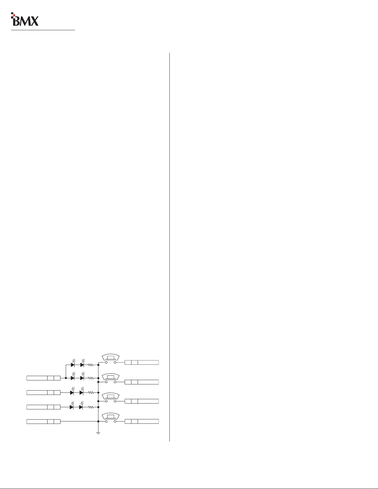
digital
2 Installation
Universal Input Module Logic and Mics
Microphone logic has three main functions: to
mute the monitor speakers in the room with a “hot”
mic; to command a hot mic warning light; and to
activate logic functions like talkback and cough.
The warning commands come from the Control
Room or Studio modules, but it is the Universal
Input modules that tell the monitor modules that
the input is a mic and where that mic is located
(control room, a studio, or an external site).
Setting a Universal input module as a mic input is done by either setting DIP switch 2, 3, 4 or
5 to On on DS1 (A input) or DS3 (B input) or,
when a console is tied into a VistaMax system, b y
assigning the input using its Room Code. The
Room Code is a VistaMax system function that
sets the room using a Session file setting that is
typically used when the mic is routed through the
VistaMax system.
Direct Mic Connections
Pages 2-58 and 2-59 summarize setting up a
Universal Input module as a direct microphone
input, utilizing a PRE99-1198 Mic P anel (simplified schematic shown below). This is typically how
mics in the control room or in a dedicated studio
are connected. Both the mic audio and the mic
logic are wired directly to an input module’s connectors. This is typically how mics are wired even
when the console is connected to a VistaMax system since the active input mic audio can be made
available as a VistaMax source—allowing the mic
audio to be routed to another console or other destination in the VistaMax system.
VistaMax Mic Connections
When a studio, voice-over booth, or other external location will be shared by multiple control
rooms, then the shared mics should be routed
through the VistaMax system. This then allows
digital
each BMX
console to independently control the mics (just as if they were directly connected
to the console) via the VistaMax system.
The shared mics and their mic panels are wired
directly to an Analog I/O and a Logic I/O card in
a VistaMax frame. The logic signals for the mic
panel are “bound” to the mic audio during setup.
Thus, selecting a mic as a source by any console
automatically routes both the audio and logic to
that console through its Net Card. Tally commands
from the console to the mic panel are routed
through the Net Card and the Logic I/O Card.
For additional networked audio information refer to the VistaMax manual (Harris # 75-52).
for PRE99-1197 or PRE9-1198)
AMBER (TALKBACK)
AMBER (COUGH)
V+ SUPPLY J1 4
ON TALLY J1 3
AMBER (OFF)
OFF TALLY J1 2
LOGIC GND J1 1
Mic Control Panel
(Simplified Schematic
TALKBACK
CR3 CR6
CR4 CR5
RED (ON)
CR8 CR7
CR1 CR2
J1: TO/FROM CONSOLE CHANNEL LOGIC
COUGH
ON
OFF
GNDD
Mic Logic To/From a BMXdigital Module
A mic panel connects to a Universal Input module using the MAIN logic connector (a simplified
S1
8 J1 TALK TO C/R
S2
7 J1 COUGH
S4
6 J1 ON
S3
5 J1 OFF
schematic is on page 2-13). To enable the remote
control inputs (On, Off, Cough, Talkback), pin 18
(Activate Logic Inputs) must jumper to the +5 VDC
supply (pin 6, 10, 11, or 12). T he On Tally output
(pin 17) drives the LEDs in the On button and
the Off Tally (pin 16) drives the LEDs in the Off
button. The other LEDs (Cough and Talkback)
connect to +5 VDC. Switches and LEDs are
commoned to Logic Ground.
To make a custom mic panel, use SPST (single
2-14
HARRIS CORPORATION
Revision C • 1/04
Page 27

digital
2 Installation
pole, single throw) momentary contact switches
with LED or lamp indicators. Lamps must be 6.3
volt type with a current draw of under 50 mA.
Tie one side of each switch and lamp to Logic
Common (pin 1, 2 or 3 on the MAIN connector).
The other side of the Cough and Talkback lamps
are tied together to Logic Active Tally (pin 15).
Each switch is tied to its logic counterpart (the
On switch goes to the On (-) input, pin 7, the Off
switch goes to Off (-) input, pin 8, etc.). The on/off
lamps are tied to their Tally outputs (On lamp to
On Tally, pin 17; Off lamp to Off Tally, pin 16).
T allies Common (pin 16) is jumpered to +5 VDC
(pin 6, 10, 11 or 12). Pin 18, Activate Logic Inputs (+), is also jumpered to +5 VDC (typically
pin 6 is used).
Input Module Logic (Universal Input,
T elc o/C odec , RLS) and Peripheral Devices
Peripheral devices are controlled through the
Start and Stop Command Pulses, or through the
Start Command Sustained logic, and the Commands Common connections.
In the basic logic connection example on pages
2-60 and 2-61, activ e low logic is used, thus Commands Common is connected to the logic ground
on the peripheral device (labeled Command Common on the Denon CD player in the example).
In the complex logic example shown on pages
2-62 and 2-63, active high logic is used, thus
Commands Common connects to +5 VDC.
Note: This voltage is more typically supplied
directly by the peripheral device in order to
prevent ground loops.
Peripheral devices control the module through
the Reset and Ready logic inputs. In the example
on pages 2-60 and 2-61, only the Read y function
is used. The Ready function performs an audio
Reset, which turns off the module without generating a Stop Command Pulse. In addition, it also
controls the Off lamp illumination.
Pages 2-62 and 2-63 show an example where
Reset (+) and Ready (+) connect to +5 VDC on
the module. The Ready (-) command and the Reset (-) command are pulled low by the active low
logic relay outputs on the peripheral device, which
all tie to the module’s Logic Ground (pin 1).
For devices requiring a steady On signal, the
Start Command Sustained output can be used.
Additional Logic Connections
There are additional logic connections on the
Session module, Control Room module, optional
Studio module, and Output 1 module.
Three 3-pin connectors on the Session module
interface remote timers so they can be reset by the
console timer reset logic. The Session module also
has factory-installed cabling for the clock and
timer , the talkback mic, the digital meters and the
meter legend display data. For more information
on the Session module’s logic connections and settings, see pages 2-32 and 2-33.
A 14-pin connector on the Control Room module carries the logic interface for the Control Room
warning light, mute, dim and talkback. An 8-pin
connector on the Control Room module controls
the External Cue input. For more information on
the Control Room module’s logic connections and
settings, see pages 2-34 to 2-38.
The optional Studio module has two 14-pin connectors to control the two studios’ logic (warning
lights, mutes, dims). The Studio module also has
two 16-pin connectors: one for the talkback audio and logic for a producer , the other for talkback
audio and logic from an external site. For more
information on the Studio module’s logic connections and settings, see pages 2-40 to 2-49.
The Output 1 module includes an 8-pin connector to control the producer’s talkback to each
mix-minus output. For more information on the
Output 1 module’s logic connections and settings,
see pages 2-50 to 2-53.
2-15
HARRIS CORPORATION
Revision C • 1/04
Page 28
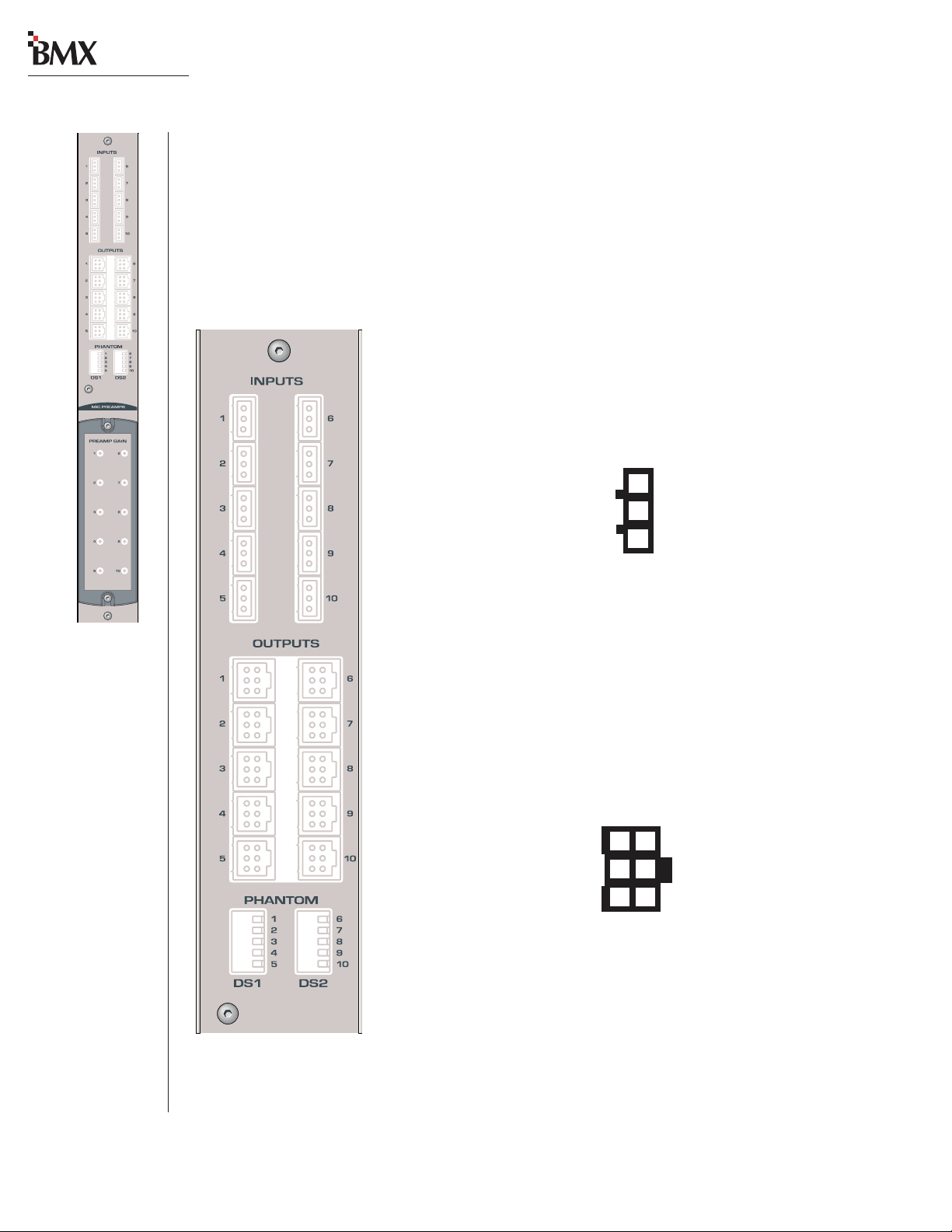
digital
2 Installation
QUICK GUIDE TO THE MICROPHONE PREAMPLIFIER MODULE
The BMX
BMX
come standard with ten mic preamps. Each 3-pin input connects to a separate mic preamp driving its
own 6-pin line-level balanced analog output connector . T he connectors are hidden b y the meter panel in
normal operation.
digital
mic preamp contains two separate PCAs with five mic preamps on each board. The
digital
-8 and -14 come standard with five mic preamps, whereas the BMX
digital
-22, -30 and -38
INPUTS
Inputs—Inputs—
Inputs— The 3-pin analog inputs accept mono microphone signals.
Inputs—Inputs—
Connect only low impedance, balanced, dynamic or condenser
microphones, with nominal mic output levels of -65 to -30 dBu, to these
inputs.
Analog Mic Inputs
High (+)
Low (-)
Shield
(wire insertion end view)
3
2
1
OUTPUTS
Outputs —Outputs —
Outputs — The 6-pin analog outputs are wired in parallel (mono)
Outputs —Outputs —
using the standard pinout sequence. This allows these outputs to connect
directly to Universal Input modules without requiring any setting changes
to be made to the Input Mode from a standard stereo input. The preamp
output signal level is +4 dBu.
Analog Preamp Outputs
Left High (+)
Left Low ( - )
Shield
(wire insertion end view)
3
2
1
6
5
4
Right High (+)
Right Low (-)
Shield
2-16
HARRIS CORPORATION
Revision C • 1/04
Page 29
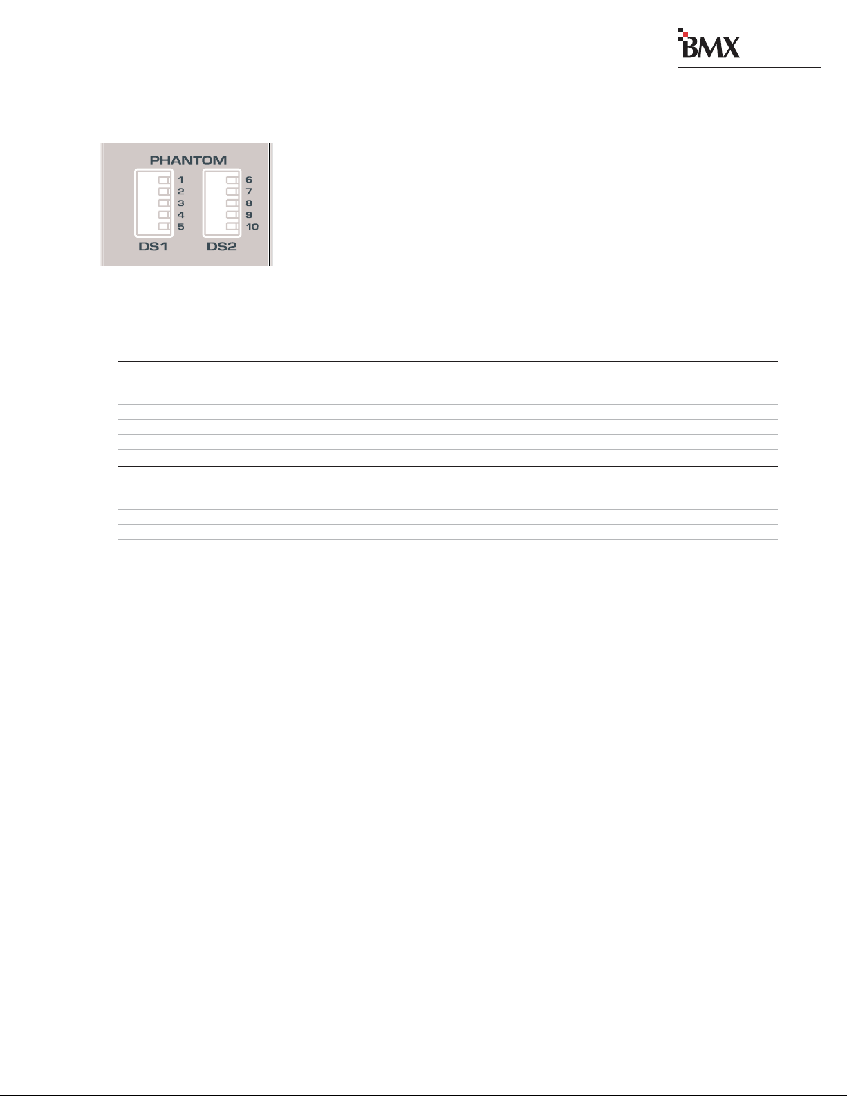
2 Installation
MICROPHONE PREAMPLIFIER MODULE SWITCHES
PHANTOM
DS1/DS2 —DS1/DS2 —
DS1/DS2 — These DIP switches set whether phantom power is applied to each mic input. The
DS1/DS2 —DS1/DS2 —
factory default setting for all switches is OFF.
Microphone Preamplifier Module Switch Definitions
# Switch Name ON Function (set to operator’s left) OFF Function (set to operator's right)
1 Mic Input #1 Phantom power on Phantom power off
2 Mic Input #2 Phantom power on Phantom power off
3 Mic Input #3 Phantom power on Phantom power off
DS1DS2*
4 Mic Input #4 Phantom power on Phantom power off
5 Mic Input #5 Phantom power on Phantom power off
digital
6 Mic Input #6 Phantom power on Phantom power off
7 Mic Input #7 Phantom power on Phantom power off
8 Mic Input #8 Phantom power on Phantom power off
9 Mic Input #9 Phantom power on Phantom power off
10 Mic Input #10 Phantom power on Phantom power off
* Optional on the BMXdigital-8 and BMXdigital-14, standard on the other frame sizes.
2-17
HARRIS CORPORATION
Revision C • 1/04
Page 30
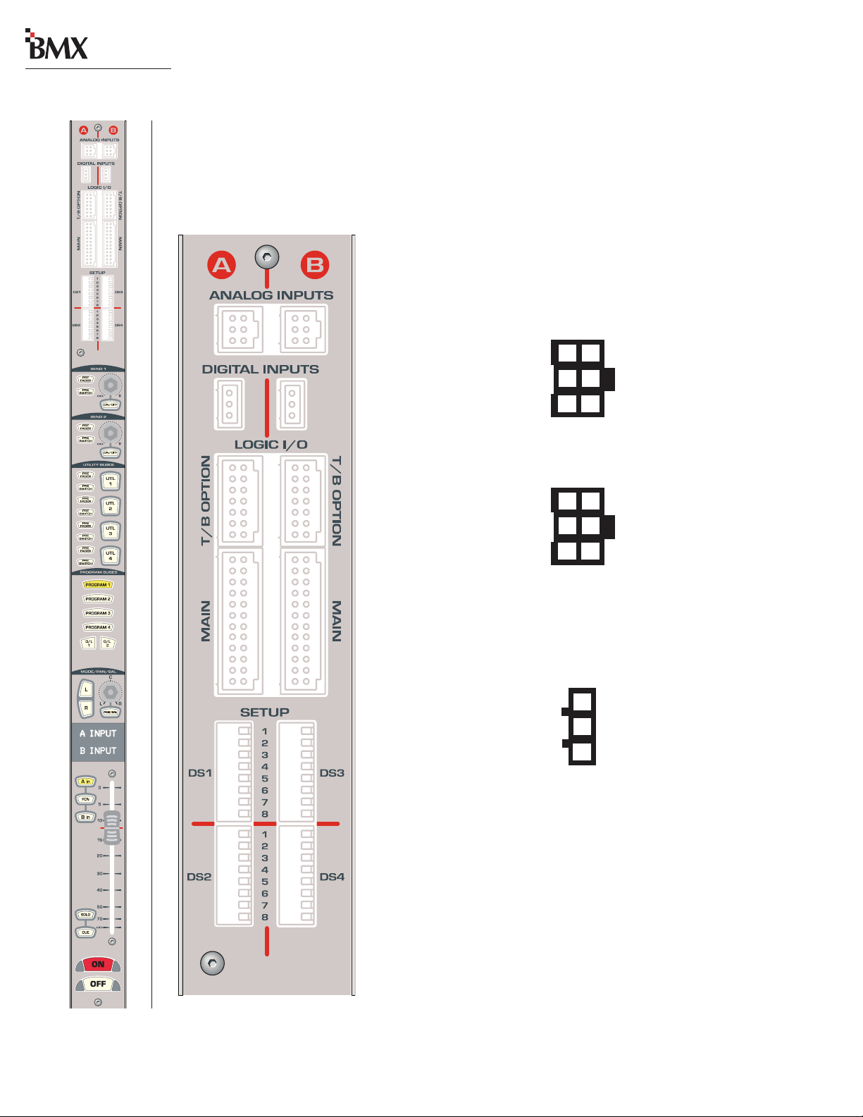
digital
2 Installation
QUICK GUIDE TO THE UNIVERSAL INPUT MODULE
Eight connectors come standard on each Universal Input module: two 6-pin analog audio input
connectors, two 3-pin digital audio input connectors , two 14-pin logic connectors, and two 24-pin logic
connectors. The connectors are hidden by the meter panel in normal operation.
AUDIO INPUTS
ANALANAL
OG INPUTOG INPUT
ANAL
OG INPUT
ANALANAL
OG INPUTOG INPUT
mono line level signals. Mono signals, like those from a preamplified
microphone, should be paralleled to the left and right inputs.
S A & B —S A & B —
S A & B — The 6-pin analog inputs accept stereo or
S A & B —S A & B —
Analog Inputs - Stereo
Left High (+)
Left Low (-)
Shield
(wire insertion end view)
3
2
1
6
5
4
Right High (+)
Right Low (-)
Shield
Analog Inputs - Mono
High (+)
Low (-)
Shield
(wire insertion end view)
DIGITDIGIT
DIGIT
DIGITDIGIT
AL INPUTAL INPUT
AL INPUT
AL INPUTAL INPUT
S A & B —S A & B —
S A & B — The two 3-pin digital inputs accept AES-3
S A & B —S A & B —
(AES/EBU) or S/PDIF signals (when the circuit shown on page 2-11 is used).
3
6
High (+)
2
5
Low (-)
1
4
Shield
Digital Inputs
High (+)
Low (-)
Shield
(wire insertion end view)
3
2
1
LOGIC I/O
T/B OPTION A & B —T/B OPTION A & B —
T/B OPTION A & B — Two 14-pin T alkback connectors allow separate
T/B OPTION A & B —T/B OPTION A & B —
A/B input control of talkback when microphone logic is active. Connects to
a PRE99-1199 Mic Remote Panel with five Talks, or a custom talkback
control panel. For additional information, see pages 2-22 and 2-23.
MAIN A & B —MAIN A & B —
MAIN A & B — Two 24-pin logic connectors allow separate A/B input
MAIN A & B —MAIN A & B —
control of the peripheral devices connected to the A and B inputs. For
additional information, see pages 2-20 and 2-21.
2-18
HARRIS CORPORATION
Revision C • 1/04
Page 31

2 Installation
UNIVERSAL INPUT MODULE SWITCHES
SETUP
DS1/DS2 —DS1/DS2 —
DS1/DS2 — These 16 DIP switches affect the logic settings for the A input. Individual switch definitions are listed below.
DS1/DS2 —DS1/DS2 —
DS3/DS4 —DS3/DS4 —
DS3/DS4 — These 16 DIP switches affect the logic settings for the B input. Individual switch definitions are listed below.
DS3/DS4 —DS3/DS4 —
Universal Input Module Switch Definitions
# Switch Name ON Function (set to operator’s left) OFF Function (set to operator's right)
1 Signal Source Digital Analog
2 CR Mute Mutes C/R speakers at module on
3 Studio 1 Mute Mutes Studio 1 speakers at module on
4 Studio 2 Mute Mutes Studio 2 speakers at module on
5 External Site Mute Mutes exter nal site speakers at module on 1No monitor muting
DS1 / DS3
6 Local On Cough Hold down On button as Cough button On button not used for Cough
7 Timer Reset Resets timer at module on No timer reset
8 Off Lamp Control Local (Off lamp follows on/off status) Remote (Off lamp follows ready logic)
1
1
1
No monitor muting
No monitor muting
No monitor muting
digital
1 Fader Start Moving Fader from/to full-off (bottom) Fader movement does not affect
turns module On/Off module On/Off
2 Start/Stop Pulses Multiple (each press of On/Off button Single (pulse is only generated when
generates another pulse) changing state, Off to On, or On to Off)
3 Start/Stop Control All (pulses are generated no matter Local (pulses are only generated by
(no mute location set) where On/Off control originates) module On/Off buttons)
Dim Function Control Disables the Dim function when Enables the Dim function (the default
(mute location is set) receiving talkback setting)
4 Sample Rate Bypasses the internal SRC (use only Uses internal SRC (normal setting)
DS2 / DS4
Converter (SRC) when the console and all the audio
sources are locked to an external reference)
2
5 Mute Setting Control Use local DIP switches to set Mute location VistaMax Room Code sets Mute location
6 Spare Switch
7 Input Level Set See table below See table below
8 Input Level Set See table below See table below
Switches 7 & 8 Table
These switches are used together to set the nominal reference levels for the A and B inputs. The factory
default settings are both OFF.
78 Analog 3Digital
Off Off +4 dBu 0 dB
Off On +6 dBu -6 dB
On Off +8 dBu -12 dB
On On -10 dBV -18 dB
1
The module logic is set as Microphone when any of these switches are set to On with a directly connected mic. When the
mic is a net source, then switch DS2/4-5 sets how the mute location is set (using a DIP switch or using Room Code).
2
Refer to page 2-11, Digital Clock Reference for details on an external reference.
3
The nominal input to achieve -20 FSD (equal to a +4 dBu output), with the fader set to the red reference line.
4
The amount of gain reduction applied to the digital input signal.
4
2-19
HARRIS CORPORATION
Revision C • 1/04
Page 32

digital
2 Installation
UNIVERSAL INPUT MODULE — MAIN LOGIC
The left connector connects to the A Input device; the right connector connects to the B Input
device.
Pins 15 and 20 have dual logic functions. With
the module set as a Mic Input (DS1 or DS3 switch
2, 3, 4, or 5 is set to ON) then pin 15 is a Logic
Active Tally and pin 20 is the Talk to Control Room
logic input. However, when the module is used as a
Line Input (DS1 or DS3 switches 2, 3, 4, and 5 all
set to OFF), then pin 15 is a Cue Tally output and
pin 20 is an external Cue command.
See pages 2-58 to 2-63
logic connections.
for examples of typical
MAIN Connector
Logic Supply +5 VDC
Logic Supply +5 VDC
Logic Supply +5 VDC
Cough (-)
Off (-)
On (-)
Logic Supply +5 VDC
Start Command Pulse
Stop Command Pulse
Logic Ground
12
11
10
24
Ready (+)
23
Start Command Sustained
22
Reset (+)
21
9
8
7
6
5
4
3
Ready (-)
20
MIC: Talk to C/R (-) LINE: Ext Cue (-)
Reset (-)
19
Activate Logic Inputs (+)
18
On Tally
17
Off Tally
16
MIC: Logic Ac tive Tally LINE: Cue Tally
15
Universal Input Module, MAIN — Simplified Logic Diagram
Reset Input (+)
Ready Input (+)
Ready Input (-)
Reset Input (-)
Activate Logic Inputs(+)
On Input (-)
Off Input (-)
Cough Input (-)
MIC: Talk To C/R (-) LINE: Cue Input (-)
22
24
21
19
18
7
8
9
20
Notes:
Opto-Isolator inputs can handle +5 to +40 VDC logic
Opto-Isolator outputs can handle up to 60 volts or 350 mA
Logic Ground
Logic Ground
(wire insertion end view)
Internal Logic
+5 volts
Tallies Common
14
2
Commands Common
13
1
Start Command Pulse
5
Stop Command Pulse
4
Start Command Sustained
23
Commands Common
13
MIC: Logic Active Tally LINE: Cue Tally
15
On T ally
17
Off T ally
16
Tallies Common
14
Logic Ground
1
Logic Ground
2
Logic Ground
3
Logic Supply +5VDC
6
Logic Supply +5VDC
10
Logic Supply +5VDC
11
Logic Supply +5VDC
12
2-20
HARRIS CORPORATION
Revision C • 1/04
Page 33

Universal Input Module MAIN Logic Signal Definitions
digital
2 Installation
PIN NAME/NUMBER
START COMMAND PULSE
(pin 5)
STOP COMMAND PULSE
(pin 4)
START COMMAND
SUSTAINED (pin 23)
COMMANDS COMMON
(pin 13)
ACTIVATE LOGIC INPUTS (+)
(pin 18)
ON (-)
(pin 7)
OFF (-)
(pin 8)
COUGH (-) (pin 9)
TALK TO C/R or CUE (-)
(pin 20)
TALLIES
FUNCTIONAL DESCRIPTION OF CONNECTION
Equivalent to a Normally Open (N/O) relay contact. A momentary “contact closure” of 220 ms is generated when
the module On b utt on i s pres sed. Typically connects to th e Re mo te St ar t l ogi c in put on t he pe ri phera l de vice.
When DS2-2 or DS4-2 is set to On, each press of the On button generates another contact closure.
Same as the Start Command Pulse, except it is initiated by the module Off button. Typically connects to the
Remote Stop or Pause logic input on the peripheral device.
Same as Start Command Pulse, except it is a maintained contact closure for as long as the module is on. Typically
connects to the Remote Start logic input on a peripheral device that cannot use a start pulse.
The Common (C) relay contact output for the three Start and Stop Command outputs. Sets whether the Start
and Stop Commands are active high (connect this pin to the logic supply voltage on the peripheral device) or
active low (connect this pin to logic ground on the peripheral device).
To enable the control inputs: On, Off, Cough, Talk/Ext Cue, tie this pin to + logic voltage (+5 to +40). When tied to
an isolated device like a mic remote panel, use the Logic Supply +5 VDC (jumper pin 18 to pin 6, 10, 11 or 12).
When pulled low, turns the module on from off, generating a Start Pulse if DS2-3 or DS4-3 is set to On. Input is
ignored if the module is already on, unless DS2-2 or DS4-2 is set On (each press generates a Start Pulse output).
When pulled low, turns the module off from on, generating a Stop Pulse if DS2-3 or DS4-3 is set to On. Input is
ignored if the module is already off, unless DS2-2 or DS4-2 is set On (each press generates a Stop Pulse output).
When pulled low, mutes the audio from all assigned buses for as long as the Cough button is pressed.
When pulled low, and the module is set as a Mic, the input audio is muted from all output buses and only routed
to the talkback bus. When set as a Line, routes the input audio to the Cue bus while the input is low.
All Tally outputs are N/O “dry contact” type outputs. Typically used to drive indicators, the outputs can sink or
source up to 60 volts at 350 mA. The “C” or common contact for all the tallies is Tallies Common (pin 14).
OFF TALLY (pin 16)
ON TALLY (pin 17)
LOGI C A C T I VE TAL LY or
CUE TALLY (pin 15)
TALLIES COMMON
(pin 14)
READY (+) & (-)
RESET (+) & (-)
READY (+) & (-)
(pins 24 & 21)
RESET (+) & (-)
(pins 22 & 19)
LOGIC SUPPLY +5 VDC
(pins 6, 10, 11, 12)
LOGIC GROUND
(pins 1, 2, 3)
This output connects to Tallies Common while the module is off when DS1-8 or DS3-8 is set to On. When
DS1-8 or DS3-8 is set to Off, then this output is controlled by the Ready logic.
This output connects to Tallies Common while the module is on.
This output connects to Tallies Common when the module is set as a M ic and the matching A or B input is
selected. When set as a Line input, the output is connected to Tallies Common while Cue is active.
The “C ” relay contact for the three Tallies, it must be tied high or low to provide the return path for the Tallies.
Typically, the tally lamps are all tied to ground and Tallies Common connects to the lamp supply voltage (+5 to
+60 VDC). If the Tallies are tied to +VDC, then this pin would tie to ground.
These complementary logic inputs require +5 to +40 VDC between the (+) input and the (-) input for activation.
This can be done by connecting an active high logic to the (+) input and grounding the (-) input, or by
supplying +5 to +40 VDC to the (+) input and an active low logic to the (-) input.
When activated while the module is on, tur ns the module off without generating a stop pulse. When activated
while the module is off, it controls the Off lamp to indicate device status. Typically, no lamp indicates the
peripheral is not ready to play, a steady lamp on indicates the device is ready, and a flashing lamp indicates the
device has already played or is not yet cued up.
When activated while the module is on, turns the module off without generating a stop pulse. Input is ignored if
the module is already off.
Module logic voltage output sources that can deliver up to 300 mA of current to isolated control panels. All pins
are simply paralleled for convenience.
Module logic ground. Should be connected to isolated control panels only.
2-21
HARRIS CORPORATION
Revision C • 1/04
Page 34

digital
2 Installation
UNIVERSAL INPUT MODULE — T/B OPTION LOGIC
The left logic connector has the talkback features for the A input; the right logic connector
has the talkback features for the B input. Talkback is only active when the module is set as a
Microphone (a mute location is set on switches
2 thru 5 on DS1 and/or DS3).
The control logic can come from a PRE991199 Mic Panel with Five Talks, or from a custom talkback panel. Each Talk command input
(Talk to Studio 1 (-), Talk to Studio 2 (-), etc.),
when held low , routes the pre-fader, pre-s witch
module audio to the selected talk destination.
Privacy, when active, prevents anyone from
monitoring the pre-switch audio in the console.
While Privacy (-) is pulled low, Privacy Tally
Command (pin 5) is tied to Privacy Common
(pin 12), to provide a low output for activ ating
a lamp or LED Privacy Activ e indicator.
T/B OPTION Connector
Logic Supply +5 VDC
Logic Ground
Privacy T ally Command
Privacy ( -)
Talk to Studio 1 Co-Host (-)
Talk to Studio 1 Host (-)
Talk to Studio 1 (-)
(wire insertion end view)
7
6
5
4
3
2
1
Logic Supply +5 VDC
14
Logic Ground
13
Privacy T ally Common
12
Talk to External (-)
11
Talk to Studio 2 Co-Host (-)
10
Talk to Studio 2 Host (-)
9
Talk to Studio 2 (-)
8
Universal Input Module, T/B OPTION — Simplified Logic Diagram
Talk to Studio 1 (-)
Talk to Studio 1 Host (-)
Talk to Studio 1 Co-Host (-)
Talk to Studio 2 (-)
Talk to Studio 2 Host (-)
Talk to Studio 2 Co-Host (-)
Talk to External (-)
Privacy (-)
1
2
3
8
9
10
11
4
5
Privacy Tally Command
Privacy Tally Common
12
Logic Ground
Internal Logic
Notes:
Opto-Isolated inputs are current limited and work
with +5 to +40 VDC logic.
Opto-Isolated outputs can sink up to 60 volts or
350 mA max. current flow.
6
Logic Ground
13
Logic Supply +5VDC
7
Logic Supply +5VDC
14
2-22
HARRIS CORPORATION
Revision C • 1/04
Page 35

Universal Input Module T/B OPTION Signal Definitions
digital
2 Installation
PIN NAME/NUMBER
TALK TO STUDIO 1 (-) (pin 1)
TALK TO STUDIO 1 HOST (-) (pin 2)
TALK TO STUDIO 1 CO-HOST (-) (pin 3)
PRIVACY (-) (pin 4)
PRIVACY TALLY COMMAND (pin 5)
TALK TO STUDIO 2 (-) (pin 8)
TALK TO STUDIO 2 HOST (-) (pin 9)
TALK TO STUDIO 2 CO-HOST (-) (pin 10)
TALK TO EXTERNAL (-) (pin 11)
PRIVACY TALLY COMMON (pin 12)
LOGIC GROUND (pins 6 & 13)
LOGIC SUPPLY +5 VDC (pins 7 & 14)
FUNCTIONAL DESCRIPTION OF CONNECTION
When pulled low, routes the module audio to the Studio 1 outputs.
When pulled low, routes the module audio to the host’s headphones in Studio 1.
When pulled low, routes the module audio to the co-host’s headphones in Studio 1.
When pulled low, prohibits the console operator from hearing the talent mic unless the channel
is turned On. Privacy applies to solo, cue, and any pre-switch assignments.
Output that goes low when Privacy is active.
When pulled low, routes the module audio to the Studio 2 outputs.
When pulled low, routes the module audio to the host’s headphones in Studio 2.
When pulled low, routes the module audio to the co-host’s headphones in Studio 2.
When pulled low, routes the module audio to the external output.
Common connection to logic ground for the Privacy Tally Command.
Module logic ground. Connects to the Talkback control panel to provide switch returns.
Module logic voltage output source that can deliver up to 300 mA of current.
2-23
HARRIS CORPORATION
Revision C • 1/04
Page 36

digital
2 Installation
QUICK GUIDE TO THE TELCO / CODEC MODULE
Three connectors come standard on the optional Telco module: one 6-pin analog audio input connector , one 3-pin digital audio input connector, and one 24-pin logic connector. The connectors are hidden
by the meter panel in normal operation.
AUDIO INPUTS
ANALANAL
OG INPUT —OG INPUT —
ANAL
OG INPUT — The 6-pin analog input accepts line level stereo or
ANALANAL
OG INPUT —OG INPUT —
mono signals. When a mono signal is connected, parallel the signal to the
left and right input pins.
Analog Inputs - Stereo
Left High (+)
Left Low (- )
Shield
(wire insertion end view)
3
2
1
6
5
4
Right High (+)
Right Low (-)
Shield
Analog Inputs - Mono
High (+)
Low (-)
Shield
(wire insertion end view)
DIGITDIGIT
AL INPUT —AL INPUT —
DIGIT
AL INPUT — The 3-pin digital input accepts AES-3
DIGITDIGIT
AL INPUT —AL INPUT —
3
2
1
(AES/EBU) or S/PDIF signals (when the circuit shown on page 2-11 is used).
High (+)
6
Low (-)
5
Shield
4
Digital Inputs
High (+)
Low (-)
3
2
LOGIC
LL
OGIC I/O —OGIC I/O —
L
OGIC I/O — The 24-pin logic connector allows control of the connected
LL
OGIC I/O —OGIC I/O —
device by the module, or external control of the module by the device. When
the device connects to the module through a switcher (router or External
RLS), source selection addressing is output from this connector . The source
(analog or digital input), whether a switcher is used and other logic selections
are configured by the SETUP DIP switches (see Switch Definitions, page 2-
25). For additional module information, see pages 2-26 and 2-27.
2-24
HARRIS CORPORATION
Revision C • 1/04
Shield
(wire insertion end view)
1
Page 37

TELCO / CODEC MODULE SWITCHES
SETUP
DS1 / DS2 —DS1 / DS2 —
DS1 / DS2 — These 16 DIP switches set logic functionality for the module, per the Telco/Codec
DS1 / DS2 —DS1 / DS2 —
Module Switch Definitions table below.
T elc o / Codec Module S witch Definitions
digital
2 Installation
# Switch Name ON Function (set to the operator’s left) OFF Function (set to the operator's right)
1 Set Telco ID On (sets the module as Telco / Codec #1)
2 Set Telco ID On (sets the module as Telco / Codec #2)
3 Set Telco ID On (sets the module as Telco / Codec #3)
4 Set Telco ID On (sets the module as Telco / Codec #4)
DS1
5 Set Telco ID On (sets the module as Telco / Codec #5)
6 Set Telco ID On (sets the module as Telco / Codec #6)
1
Off
1
Off
1
Off
1
Off
1
Off
1
Off
7 Signal Source Digital Input Analog Input
8 Timer Reset Resets timer at module on No timer reset
1 Off Lamp Control Local (Off lamp follows module on/off status) Ready (External device controls lamp)
2 Fader Start/Stop Fader movement, from full off, turns Fader movement does not affect
module on; to full off, turns module off. module on/off
3 Sample Rate Bypasses the internal SRC (use only Uses internal SRC (normal setting)
Converter (SRC) when the console and all the audio
sources are locked to an external reference)
4 Source Type Switcher (VistaMax or External RL S i s us e d ) Di rect (device plugs into module)
DS2
5 Switcher Type VistaMax (see Appdx. A about other routers) Exter nal RLS (PRE99-947)
2
6 O/L & Record Source Pre-fader with module off (only when Post-fader regardless of module on/off
Session module switch 6 is set for Pre-Fader)
7 Input Level See DS2 table below See DS2 table below
8 Input Level See DS2 table below See DS2 table below
DS2 — Switches 7 and 8
These switches are used together to set the nominal input level. The factory default is both OFF.
7 8 Analog
3
Off Off +4 dBu 0 dB
Off On +6 dBu -6 dB
On Off +8 dBu -12 dB
On On -10 dBV -18 dB
1
Caution: Set only one of these six DIP switches to ON. This setting identifies the module, affecting signal routing and
module controls. Each Telco module in the console MUST have a unique ID setting.
2
Refer to page 2-11, Digital Clock Referenc e for details.
3
The nominal analog input to achieve -20 FSD (equal to a +4 dBu output), with the fader set to the red reference line.
4
The amount of gain reduction applied to the digital input.
Digital
4
2-25
HARRIS CORPORATION
Revision C • 1/04
Page 38

digital
2 Installation
TELCO / CODEC MODULE — LOGIC I/O
The 24-pin LOGIC I/O connector allows the
module to control, or be controlled by, the device
attached to the module.
A device can connect directly to the module or it
can connect through a switcher . Two types of switchers are supported: VistaMax and the PRE99-947
External Remote Line Selector (Ext. RLS). The
source (switcher or direct) and the switcher type
(VistaMax or Ext. RLS) are set via DIP switches
DS2-4 and DS2-5.
When the module connects to an Ext. RLS , several logic connections (pins 15, 16, 17 and 23) become RLS address outputs. This change occurs only
when DS2-4 is set ON and DS2-5 is set to OFF.
When a VistaMax or other router is used (DS2-5 is
set ON), these pins do not change function since
addressing is done through the Session module.
LOGIC I/O Connector
Logic Supply +5 VDC
Logic Supply +5 VDC
Logic Supply +5 VDC
no connection
Off (-)
On (-)
Logic Supply +5 VDC
Start Command Pulse
Stop Command Pulse
Logic Ground
Logic Ground
Logic Ground
(wire insertion end view)
12
11
10
24
Ready (+)
23
Start Command Sustained / RLS-3
22
Reset (+)
9
21
Ready (-)
20
8
7
6
5
4
3
2
1
no connection
19
Reset (-)
18
Activate Logic Inputs (+)
17
On Tally / RLS-2
16
Off Tally / RLS-1
15
Logic Active Tally / RLS-0
14
Tallies/ RLS-0, -1, -2 Common
13
Commands/ RLS-3 Common
Telco / Codec Module, Logic I/O — Simplified Logic Diagram
Reset (+)
Ready (+)
Ready (-)
Reset (-)
Activate Logic Inputs (+)
On (-)
Off (-)
Logic Ground
Logic Ground
Logic Ground
Logic Supply +5VDC
Logic Supply +5VDC
Logic Supply +5VDC
Logic Supply +5VDC
22
24
21
19
18
7
8
1
2
3
6
10
11
12
Start Command Pulse
5
4 Stop Command Pulse
Direct / Router: Start Command Sustained
23
Ext. RLS Switcher: RLS-3
Commands Common / RLS-3 Common
13
Direct / Router: Logic Active Tally
15
Ext. RLS Switcher: RLS-0
Internal Logic
Notes:
Opto-Isolated inputs are current limited and work with +5 to +40 VDC logic.
Opto-Isolated outputs can sink up to 60 volts or 350 mA max. current flow.
Direct / Router: On Tally
17
Ext. RLS Switcher: RLS-2
Direct / Router: Off Tally
16
Ext. RLS Switcher: RLS-1
Tallies Common / RLS-0, -1, -2 Common
14
2-26
HARRIS CORPORATION
Revision C • 1/04
Page 39

Telco / Codec Module LOGIC I/O Logic Signal Definitions
digital
2 Installation
PIN NAME/NUMBER
START COMMAND PULSE
(pin 5)
STOP COMMAND PULSE
(pin 4)
START COMMAND
SUSTAINED / RLS-3
(pin 23)
COMMANDS / RLS-3
COMMON
(pin 13)
ACTIVATE LOGIC INPUTS (+)
(pin 18)
ON (-) (pin 7)
OFF (-) (pin 8)
TALLIES
OFF TALLY / RLS-1
(pin 16)
FUNCTIONAL DESCRIPTION OF CONNECTION
Equivalent to a Normally Open (N/O) relay contact. A momentary “contact closure” of 220 ms is generated each
time the module turns on from off. Typically connects to the Remote On logic input on the peripheral device.
Same as the Start Command Pulse, except it is initiated by the module Off button. Typically connects to the
Remote Stop or Off logic input on the peripheral device.
Direct: Same as Star t Command Pulse, except it is a maintained contact closure for as long as the module is on.
Typically connects to the Remote On logic input on a peripheral device that cannot use a start pulse.
Ext. RLS: Outputs addressing bit 3.
The Common (C) relay contact output for the three Start and Stop Command outputs. Sets whether the Start
and Stop Commands are active high (connect this pin to the logic supply voltage on the peripheral device) or
active low (connect this pin to logic ground on the peripheral device).
To enable the control inputs: On, Off, tie this pin to + logic voltage (+5 to +40). When tied to an isolated device
like a remote panel, use the Logic Supply +5 VDC (jumper pin 18 to pin 6, 10, 11 or 12).
When pulled low, tur ns the module on. Input is ignored if the module is already on.
When pulled low, turns the module off. Input is ignored if the module is already off.
All Tally outputs are N/O “dry contact” type outputs. Typically used to drive indicators, the outputs can sink or
source up to 60 volts at 350 mA. The “C” or common contact for all the tallies is Tallies Common (pin 14).
Direct: This output connects to Tallies Common while the module is off. When DS2-1 is set OFF, then this output
is controlled by the Ready logic. Ext. RLS: Outputs addressing bit 1.
ON TALLY / RLS-2 (pin 17)
LOGIC ACTIVE TALLY / RLS-0
(pin 15)
TA L LIES / RL S-0, -1, -2
COMMON
(pin 14)
READY (+) & (-)
RESET (+) & (-)
READY (+) & (-)
(pins 24 & 21)
RESET (+) & (-)
(pins 22 & 19)
LOGIC SUPPLY +5 VDC
(pins 6, 10, 11, 12)
LOGIC GROUND
(pins 1, 2, 3)
Direct: This output connects to Tallies Common while the module is on. Ext. RLS: Outputs addressing bit 2.
Direct: This output connects to Tallies Common when module is powered up.
Ext. RLS: Outputs addressing bit 0.
The “C ” relay contact for the three Tallies, it must be tied high or low to provide the return path for the Tallies.
Typically, the tally lamps are all tied to ground and Tallies Common connects to the lamp supply voltage (+5 to
+60 VDC). If t he Tallies are tied to +VDC, then this pin would tie to ground.
These complementary logic inputs require +5 to +40 VDC between the (+) input and the (-) input for activation.
This can be done by connecting an active high logic to the (+) input and grounding the (-) input, or by
supplying +5 to +40 VDC to the (+) input and an active low logic to the (-) input.
When activated while the module is on, turns the module off without generating a stop pulse. When activated
while the module is off, it controls the Off lamp to indicate device status. Typically, no lamp indicates the
peripheral is not ready to play, a steady lamp on indicates the device is ready, and a flashing lamp indicates the
device has already played or is not yet cued up.
When activated while the module is on, turns the module off without generating a stop pulse. Input is ignored if
the module is already off.
Module logic voltage output sources that can deliver up to 300 mA of current to isolated control panels. All pins
are simply paralleled for convenience.
Module logic ground. Should be connected to isolated control panels only.
2-27
HARRIS CORPORATION
Revision C • 1/04
Page 40

digital
2 Installation
QUICK GUIDE TO THE REMOTE LINE SELECTOR (RLS) MODULE
Three connectors come standard on the optional Remote Line Selector (RLS) module: one 6-pin
analog audio input connector , one 3-pin digital audio input connector, and one 24-pin logic connector.
The connectors are hidden by the meter panel in normal operation.
AUDIO INPUTS
ANALANAL
OG INPUT —OG INPUT —
ANAL
OG INPUT — The 6-pin analog input accepts stereo signals or
ANALANAL
OG INPUT —OG INPUT —
mono signals. When a mono input is used, parallel the signal to the left
and right inputs.
Analog Inputs - Stereo
Left High (+)
Left Low ( - )
Shield
(wire insertion end view)
3
2
1
6
5
4
Right High (+)
Right Low (-)
Shield
Analog Inputs - Mono
High (+)
Low (-)
Shield
(wire insertion end view)
DIGITDIGIT
AL INPUT —AL INPUT —
DIGIT
AL INPUT — The 3-pin digital input accepts AES-3
DIGITDIGIT
AL INPUT —AL INPUT —
3
2
1
(AES/EBU) or S/PDIF signals (when the circuit shown on page 2-11 is used).
High (+)
6
Low (-)
5
Shield
4
Digital Inputs
High (+)
Low (-)
Shield
(wire insertion end view)
3
2
1
LOGIC
LL
OGIC I/O —OGIC I/O —
L
OGIC I/O — The 24-pin logic connector controls the device connected
LL
OGIC I/O —OGIC I/O —
to the module. Devices typically connect through a switcher (an External
RLS under module control or a router), although a device can connect
directly to the module as well. The source type and switcher type are
configured via the module’s SETUP DIP switches (settings listed on page 2-
29). Logic connections vary depending on the type of device connection.
For more information, see pages 2-30 and 2-31.
2-28
HARRIS CORPORATION
Revision C • 1/04
Page 41

2 Installation
REMOTE LINE SELECTOR (RLS) MODULE SWITCHES
SETUP
SS
etup —etup —
S
etup — These eight DIP switches set logic functionality for the module per the Switch
SS
etup —etup —
Definitions table below.
Remote Line Selector (RLS) Module Switch Definitions
# Switch Name ON Function (set to operator’s left) OFF Function (set to operator's right)
1 Signal Source Digital Analog
2 Timer Reset Resets timer at module on No timer reset
3 Bypass Sample Rate Bypasses internal SRC (use only when Uses internal SRC (normal setting)
Converter (SRC) the console and all the audio sources
are locked to an external reference)
4 Source Type Switcher (VistaMax or External RLS) Direct
5 Switcher Type VistaMax (see Appdx. A about other routers) External RLS (PRE99-947)
6 Spare Switch
7 Input Level Set See table below See table below
8 Input Level Set See table below See table below
1
digital
SETUP — Switches 7 and 8
These switches are used together to set the nominal reference level for the inputs. The factory default
settings are both OFF.
78 Analog 2Digital
Off Off +4 dBu 0 dB
Off On +6 dBu -6 dB
On O ff +8 dBu -12 dB
On On -10 dBV -18 dB
1
Refer to page 2-11, D igital Clock Reference for details.
2
The nominal analog input to achieve -20 FSD (equal to a +4 dBu output), with the fader set to the red reference line.
3
The amount of gain reduction applied to the digital input.
3
2-29
HARRIS CORPORATION
Revision C • 1/04
Page 42

digital
2 Installation
REMOTE LINE SELECTOR MODULE — LOGIC I/O
The 24-pin LOGIC I/O connector allows the RLS
module to control, or to be controlled b y , the device
connected to the module. A device can connect directly to the module, but more commonly input selection would be done through a switcher . Two types
of switchers are supported: VistaMax (or other routers) and the PRE99-947 External Remote Line Selector (Ext. RLS).
The source type (switcher or direct) and the
switcher type (VistaMax or Ext. RLS) are set via
the module’s SETUP DIP switches (see page 2-29).
When the module connects to an Ext. RLS , several logic connections (pins 15, 16, 17 and 23) become RLS address outputs. This change occurs only
when DS2-4 is set ON and DS2-5 is set to OFF.
When a VistaMax or other router is used (DS2-5 is
set ON), these pins do not change function since
addressing is done through the Session module.
LOGIC I/O Connector
Logic Supply +5 VDC
Logic Supply +5 VDC
Logic Supply +5 VDC
no connection
Off (-)
On (-)
Logic Supply +5 VDC
Start Command Pulse
Stop Command Pulse
Logic Ground
Logic Ground
Logic Ground
(wire insertion end view)
12
11
10
Ready (+)
24
Start Command Sustained / RLS-3
23
Reset (+)
22
9
8
7
6
5
4
3
2
1
Ready (-)
21
no connection
20
Reset (-)
19
Activate Logic Inputs (+)
18
On Tally / RLS-2
17
Off Tally / RLS-1
16
Logic Active Tally / RLS-0
15
Tallies / RLS-0, RLS-1, RLS-2 Common
14
Commands / RLS-3 Common
13
Remote Line Selector (RLS) Module, LOGIC I/O — Simplified Logic Diagram
Reset (+)
Ready (+)
Ready (-)
Reset (-)
Activate Logic Inputs (+)
On (-)
Off (-)
Logic Ground
Logic Ground
Logic Ground
Logic Supply +5VDC
Logic Supply +5VDC
Logic Supply +5VDC
Logic Supply +5VDC
22
24
21
19
18
7
8
1
2
3
6
10
11
12
Internal Logic
Notes:
Opto-Isolated inputs are current limited and work with +5 to +40 VDC logic.
Opto-Isolated outputs can sink up to 60 volts or 350 mA max. current flow.
Start Command Pulse
5
4 Stop Command Pulse
Direct / Router: Start Command Sustained
23
Ext. RLS Switcher: RLS-3
Commands Common / RLS-3 Common
13
Direct / Router: Logic Active Tally
15
Ext. RLS Switcher: RLS-0
Direct / Router: On Tally
17
Ext. RLS Switcher: RLS-2
Direct / Router: Off Tally
16
Ext. RLS Switcher: RLS-1
Tallies Common / RLS-0, -1, -2 Common
14
2-30
HARRIS CORPORATION
Revision C • 1/04
Page 43

RLS Module LOGIC I/O Logic Signal Definitions
digital
2 Installation
PIN NAME/NUMBER
START COMMAND PULSE
(pin 5)
STOP COMMAND PULSE
(pin 4)
START COMMAND
SUSTAINED / RLS-3
(pin 23)
COMMANDS / RLS-3
COMMON
(pin 13)
ACTIVATE LOGIC INPUTS (+)
(pin 18)
ON (-) (pin 7)
OFF (-) (pin 8)
TALLIES
OFF TALLY / RLS-1
(pin 16)
FUNCTIONAL DESCRIPTION OF CONNECTION
Equivalent to a Normally Open (N/O) relay contact. A momentar y “c ontact closure” of 220 ms is generated each
time the module turns on from off. Typically connects to the Remote On logic input on the peripheral device.
Same as the Start Command Pulse, except it is initiated by the module Off button. Typically connects to the
Remote Stop or Off logic input on the peripheral device.
Direct: Same as Start Command Pulse, except it is a maintained contact closure for as long as the module is on.
Typically conne c ts to t he Rem ote O n lo gi c in put on a p eripheral device that cannot use a start pulse.
Ext. RLS: Outputs addressing bit 3.
The Common (C) relay contact output for the three Start and Stop Command outputs. Sets whether the Start
and Stop Commands are active high (connect this pin to the logic supply voltage on the peripheral device) or
active low (connect this pin to logic ground on the peripheral device).
To enable the control inputs: On, Off, Cough, Talk to C/R, tie this pin to + logic voltage (+5 to +40). When tied to
an isolated device like a remote panel, use the Logic Supply +5 VDC (jumper pin 18 to pin 6, 10, 11 or 12).
When pulled low, turns the module on, generating a Start Pulse. Input is ignored if the module is already on.
When pulled low, turns the module off, generating a Stop Pulse. Input is ignored if the module is already off.
All Tally outputs are N/O “dry contact” type outputs. Typically used to drive indicators, the outputs can sink or
source up to 60 volts at 350 mA. The “C” or common contact for all the tallies is Tallies Common (pin 14).
Direct: This output connects to Tallies Common while the module is off. When DS2-1 is set OFF, then this output
is controlled by the Ready logic. Ext. RLS: Outputs addressing bit 1.
ON TALLY / RLS-2 (pin 17)
LOGIC ACTIVE TALLY / RLS-0
(pin 15)
TALLIES / RLS-0, -1, -2
COMMON
(pin 14)
READY (+) & (-)
RESET (+) & (-)
READY (+) & (-)
(pins 24 & 21)
RESET (+) & (-)
(pins 22 & 19)
LOGIC SUPPLY +5 VDC
(pins 6, 10, 11, 12)
LOGIC GROUND
(pins 1, 2, 3)
Direct: This output connects to Tallies Common while the module is on. Ext. RLS: Outputs addressing bit 2.
Direct: This output connects to Tallies Common when module is p owered up.
Ext. RLS: Outputs addressing bit 0.
The “C ” relay contact for the three Tallies, it must be tied high or low to provide the return path for the Tallies.
Typically, the tally lamps are all tied to ground and Tallies Common connects to the lamp supply voltage (+5 to
+60 VDC). If the Tallies are tied to +VDC, then this pin would tie to ground.
These complementary logic inputs require +5 to +40 VDC between the (+) input and the (-) input for activation.
This can be done by connecting an active high logic to the (+) input and grounding the (-) input, or by
supplying +5 to +40 VDC to the (+) input and an active low logic to the (-) input.
When activated while the module is on, turns the module off without generating a stop pulse. When activated
while the module is off, it controls the Off lamp to indicate device status. Typically, no lamp indicates the
peripheral is not ready to play, a steady lamp on indicates the device is ready, and a flashing lamp indicates the
device has already played or is not yet cued up.
When activated while the module is on, turns the module off without generating a stop pulse. Input is ignored if
the module is already off.
Module logic voltage output sources that can deliver up to 300 mA of current to isolated control panels. All pins
are simply paralleled for convenience.
Module logic ground. Should be connected to isolated control panels only.
2-31
HARRIS CORPORATION
Revision C • 1/04
Page 44

digital
2 Installation
QUICK GUIDE TO THE SESSION MODULE
Four user connectors come standard on the Session module: one 10base-T connector (DATA) and
three 3-pin EXT. TIMER connectors. There are also three meter panel connectors, which are factory
connected. All connectors are hidden by the meter panel in normal operation.
INPUTS/OUTPUTS
DADA
TT
A —A —
DA
T
A — Connect a standard CAT-5 cable to this 10base-T connector to
DADA
TT
A —A —
tie the BMXdigital Server into a Local Area Network (LAN). See Chapter 4 for
more information on configuring and using the BMXdigital Server.
LOGIC OUTPUTS
EXEX
T T
TIMER —TIMER —
EX
T
TIMER — Three 3-pin External Timer connectors are available to
EXEX
T T
TIMER —TIMER —
reset external event timers. For more information, see page 2-33.
TO METER PANEL
LEGENDS —LEGENDS —
LEGENDS — Factory harnessed connector that outputs the alphanumeric
LEGENDS —LEGENDS —
meter names.
METERS —METERS —
METERS — Factory harnessed connector that outputs the meter level
METERS —METERS —
data.
TIMER / TIMER /
TIMER /
TIMER / TIMER /
from the meter panel-mounted talkback microphone and the timer control
signals from the Session module Start, Stop, Reset, and Hold buttons.
TB MIC —TB MIC —
TB MIC — Factory harnessed connector that has the audio
TB MIC —TB MIC —
RESET (SEE MANUAL)
RESET RESET
RESET
RESET RESET
Typically, this switch is
no normal operational use since this switch does not reset the DSP cards nor
the BMXdigital Server–it only resets the input module operational
parameters.
2-32
HARRIS CORPORATION
Revision C • 1/04
——
— This switch resets all operational parameters on all modules.
——
only used for test or servicing purposesonly used for test or servicing purposes
only used for test or servicing purposes and has
only used for test or servicing purposesonly used for test or servicing purposes
Page 45

2 Installation
SESSION MODULE SWITCHES
SETUP
SETUP —SETUP —
SETUP — These eight DIP switches affect logic settings for the meters and for the entire console per
SETUP —SETUP —
the Session Module Switch Definitions table below.
Session Module Switch Definitions
# Switch Name ON Function (set to operator’s left) OFF Function (set to operator’s right)
1 Meter Display Mode Average only Average and peak
2 Auxiliary Meter Cue is displayed (when both Cue Solo is displayed (when both Cue
Display Priority and Solo are selected) and Solo are selected)
3 Channel On Cancels Cue and Solo are canceled when Cue and Solo are not affected by
Cue or Solo channel is turned on channel on
4 Cue Lamp Control Cue indicators blink when Cue is on Cue indicators are solid when Cue is on
5 Solo function latch Solo buttons are latched (alternate action) Solo buttons are momentary
6 Off-Line buses All modules Post-fader, but Pre-Switch Universal/RLS, Pre-fader and Pre-Switch *
signal source * See page 2-25 about an additional Telco module switch that affects their Off-Line source.
7 PGM/UTL 1- 4 function BMXd-8 sequential meter source selection Meter switching for all other frame sizes
8 Spare Switch
Console-wide Settings Meters
digital
SESSION MODULE — EXTERNAL TIMER
These connectors reset up to three external timers (like the timer
in the PRE99-1211 Turret Clock & Timer). They operate independently of the Session module timer buttons. The two active pins
(pins 2 and 3) momentarily short together when a reset command
is issued by turning on a module that is set to reset the timer.
EXT TIMER 1, 2, 3 Connectors
Auto Reset Common
3
Auto Reset Command
2
1
no connection
(wire insertion end view)
Session Module EXT TIMER Logic Signal Definitions
PIN NAME/NUMBER
AUTO RESET COMMAND
(pin 2)
AUTO RESET COMMON
(pin 3)
FUNCTIONAL DESCRIPTION OF CONNECTION
Equivalent to a Normally Open (N/O) relay contact. A momentar y “co ntact closure” of 220 ms (to the Auto Reset
Common pin) is generated each time a module is turned on that has the Timer Reset Command active (DS1-7 or
DS3-7 is set ON). Connect this pin to J4-4 on the PRE99-1211 timer.
The Common (C) relay contact for the Auto Reset Command. Tie this pin to the Timer’s logic ground pin when an
active low logic is required or tie it to the Timer’s Logic Voltage when an active high logic is required. Connect
this pin to J4-3 on the PRE99-1211 timer.
Session Module, Ex ternal Timer Reset —
Simplified Logic Diagram
+3.3VDC
Internal Logic
Notes:
There are no connections to pin 1.
Opto-Isolated outputs can sink up to 60 volts or
350 mA max. current flow.
2
Auto Reset Command
Auto Reset Common
3
2
Auto Reset Command
Auto Reset Common
3
2
Auto Reset Command
Auto Reset Common
3
EXT TIMER 1
EXT TIMER 2
EXT TIMER 3
2-33
HARRIS CORPORATION
Revision C • 1/04
Page 46

digital
2 Installation
CONTROL ROOM MODULE CONNECTORS
Thirteen connectors come standard on each Control Room module: five 6-pin analog audio input
connectors, six 6-pin analog audio output connectors, one 14-pin logic connector, and one 8-pin logic
connector. The connectors are hidden by the meter panel in normal operation.
AUDIO INPUTS
EXEX
T-1,T-1,
EX EX
T-2,T-2,
EX EX
T-3,T-3,
EX EX
T-4,T-4,
EX
T-1,
EX
T-2,
EX
T-3,
EXEX
T-1,T-1,
EX EX
T-2,T-2,
EX EX
T-3,T-3,
EX
EX EX
accept stereo or mono signals from external monitor sources such as offair tuners, a synthetic air monitor, VistaMax monitor output, etc. When a
mono source is connected, parallel the signal to the left and right inputs.
Analog Inputs / Outputs - Stereo
CUE IN — CUE IN —
T-4,
CUE IN — These 6-pin analog inputs
T-4,T-4,
CUE IN — CUE IN —
Left High (+)
Left Low (- )
Shield
(wire insertion end view)
3
2
1
6
5
4
Right High (+)
Right Low (-)
Shield
Analog Inputs - Mono
High (+)
Low (-)
Shield
(wire insertion end view)
3
2
1
High (+)
6
Low (-)
5
Shield
4
AUDIO OUTPUTS
MONITMONIT
MONIT
MONITMONIT
——
— The 6-pin analog outputs for the control room monitor speaker amplifier
——
(Monitor); three outputs for the headphone amplifiers for the board operator
(Operator), co-host or host (Co-host) and for one or more guests (Guest); a
Cue amplifier feed (Cue); and a separate Talk to Control Room output
(Talkback) for a powered Talkback monitor speaker or amplifier.
OR,OR,
OR,
OR,OR,
OPER OPER
OPER
OPER OPER
AA
TT
A
T
AA
TT
OR,OR,
CO-HOST CO-HOST
OR,
CO-HOST
OR,OR,
CO-HOST CO-HOST
,,
GUEST GUEST
,
GUEST
,,
GUEST GUEST
,,
CUE CUE
,
CUE
,,
CUE CUE
,,
TALKBTALKB
,
TALKB
,,
TALKBTALKB
AA
CKCK
A
CK
AA
CKCK
LOGIC I/O
LL
OGIC —OGIC —
L
OGIC — This 14-pin connector has four “relay” outputs (Control Room
LL
OGIC —OGIC —
warning, mute, dim, and talkback) and two remote inputs (Dim and
Mute). See pages 2-36 and 2-37 for details on these signals.
CUE CNTL —CUE CNTL —
CUE CNTL — This 8-pin connector has an external cue control input
CUE CNTL —CUE CNTL —
See page 2-38 for details on this signal.
2-34
HARRIS CORPORATION
Revision C • 1/04
Page 47

2 Installation
CONTROL ROOM MODULE SWITCHES
SETUP
SETUP —SETUP —
SETUP — These eight DIP switches affect logic functionality for the module per the Control Room
SETUP —SETUP —
Module Switch Definitions below.
Control Room Module Switch Definitions
# Switch Name ON Function (set to operator’s left) OFF Function (set to operator's right)
1 Headphone AutoCue Cue is summed to the left channel, monitor Cue feeds both headphone channels
functions (when active) is summed to the right channel (Cue in stereo), monitor is muted
2 Talkback to Co-Host Adds talkback to the co-host’s headphones Does not add talkback to the co-host’s
Headphones headphones
3 Talkback to Cue Adds talkback audio to the Cue output Talk back audio does not go to Cue
4 Dim Monitors when Monitors dim by 12 dB when receiving Monitors do not dim when receiving
Receiving Talkback talkback talkback
5 Auto-switch External Automatic switching from External No automatic monitor source switching
Inputs 1 & 2
6 Auto-switch External Automatic switching from External No automatic monitor source switching
Inputs 3 & 4
7 Spare Switch
8 Spare Switch
1
Input 1 to Input 2 while there is a hot mic with a hot mic in the Control Room
in the Control Room
2
Input 3 to Input 4 while there is a hot mic with a hot mic in the Control Room
in the Control Room
digital
1
When set to ON, the monitor source automatically switches between External Input 1 (which typically has the
off-air monitor, with delay) and External Input 2 (which has a synthetic air signal with little or no delay). When
External 1 is selected as the monitor source, and a Control Room mic module is turned on, the monitor source
automatically changes to External Input 2. When all Control Room mic modules are off, then External Input 1 is
automatically selected.
2
When set to ON, the monitor source automatically switches between External Input 3 (which would be the off-air
monitor, with delay), and External Input 4 (which has a synthetic air signal with little or no delay). When External 3
is selected as the monitor source, and a Control Room mic module is turned on, the monitor source automatically
changes to External Input 4. When all Control Room mic mo dules are off, then External Input 3 is automatically
selected.
2-35
HARRIS CORPORATION
Revision C • 1/04
Page 48

digital
2 Installation
CONTROL ROOM MODULE — LOGIC
The 14-pin LOGIC connector has the hot mic
warning output (Warning Relay) for a control
room warning lamp interface, two remote inputs; Mute (-) and Dim (-), and various tally
outputs (Mute, Dim and Talkback Tally).
The two Warning Relay outputs short together when a control room mic is on. They can
be used as two “dry contacts” or one can be jumpered to + voltage to present a high logic, or to
ground to present a low logic (on isolated
ground devices, these can come from the Logic
Supply +5 VDC or Logic Ground on the connector).
Note: The warning relay and control room
mute functions are only activated by modules
set as control room microphones (DS1/DS3,
switch 2 is On) and that are assigned to at least
one PGM or UTL bus.
LOGIC Connector
Logic Supply +5 VDC
Logic Supply +5 VDC
Warning Relay
Warning Relay
Logic Ground
Logic Ground
Logic Ground
(wire insertion end view)
7
6
5
4
3
2
1
Activate Logic Inputs (+)
14
Talkback Tally
13
Dim Tally
12
Mute T ally
11
Tallies Common
10
Dim (-)
9
Mute (-)
8
Control Room Module, LOGIC — Simplified Logic Diagram
Activate Logic Inputs (+)
Mute Input (-)
Dim Input (-)
Notes:
Opto-Isolated inputs are current limited and work
with +5 to +40 VDC logic.
Opto-Isolated outputs can sink up to 60 volts or
350 mA max. current flow.
14
8
9
Internal Logic
Warning Relay
4
Warning Relay
5
Dim Tally
12
Mute Tally
11
Talkback Tally
13
Tallies Common
10
Logic Ground
1
Logic Ground
2
Logic Ground
3
Logic Supply +5VDC
7
Logic Supply +5VDC
6
2-36
HARRIS CORPORATION
Revision C • 1/04
Page 49

Control Room Module, LOGIC, Logic Signal Definitions
digital
2 Installation
PIN NAME/NUMBER
WARNING RELAY
(pins 4 and 5)
MUTE TALLY (pin 11)
DIM TALLY (pin 12)
TALKBACK TALLY (pin 13)
TALLIES COMMON (pin 10)
ACTIVATE LOGIC INPUTS (+)
(pin 14)
MUTE (-) (pin 8)
DIM (-) (pin 9)
LOGIC SUPPLY +5 VDC
(pins 6 and 7)
LOGIC GROUND
(pins 1, 2, 3)
FUNCTIONAL DESCRIPTION OF CONNECTION
A pair of Normally Open (N/O) relay contacts. The t wo contacts main tain a “contact closure” while a Control
Room mic module (with DS1-2 or DS3-2 set to ON) is turned on. The two pins can be used as a “dry contact”
output, or one can be connected to the Warning Lamp control input while the other is tied to ground (to
generate an active low logic output) or to + logic voltage (to generate an active high logic output).
This Normally Open (N/O) contact connects to Tallies Common while the control room speakers are muted.
This Normally Open (N/O) contact connects to Tallies Common while the control room speakers are
dimmed.
This Normally Open (N/O) contact connects to Tallies Common while Talkback is received by the Control
Room.
This pin must be tied high or low to provide the return path for the various Tally outputs. Typically, the tally
lamps (or external relays) are all tied to ground and Tallies Common is the source for the lamp / relay supply
voltage (+5 to +60 VDC). If the Tallies / relays are tied to +VDC, then this pin ties to ground.
To enable the control inputs: Mute and Dim, tie this pin to + logic voltage (+5 to +40). When tied to an
isolated device like a remote panel, use the Logic Supply +5 VDC (jumper pin 14 to pin 6 or 7).
When pulled low, mutes the Control Room monitors.
When pulled low, dims the Control Room monitors by 12 dB.
Module logic voltage output sources that can deliver up to 300 mA of current to isolated control panels.
The pins are simply paralleled for convenience.
Module logic ground. Should be connected to isolated control panels only.
2-37
HARRIS CORPORATION
Revision C • 1/04
Page 50

digital
g
2 Installation
CONTROL ROOM MODULE — CUE CONTROL LOGIC
The 8-pin CUE CNTRL connector has the External Cue on/off logic. Only four pins (1 - 4)
are used on this connector .
Typically the Cue (+) pin is jumpered to Logic
Supply +5 VDC and the Cue (-) and Logic
Ground go to an External Cue switch (maintained SPST). The logic connector is hidden b y
the meter panel in normal operation.
Control Room Module, CUE CNTRL — Simplified Logic Diagram
CUE CNTRL Connector
Logic Supply +5 VDC
Cue (+)
Cue (-)
Logic Ground
(wire insertion end view)
no connection
8
4
no connection
7
3
no connection
6
2
no connection
5
1
Cue Input (+)
Cue Input (-)
Notes:
Opto-Isolated inputs are current
limited and work with +5 to +40 VDC
ic.
lo
3
2
Internal Logic
Control Room Module, CUE CNTRL , Logic Signal Definitions
PIN NAME/NUMBER
CUE (+)
(pin 3)
CUE (-)
(pin 2)
LOGIC SUPPLY +5 VDC
(pin 4)
FUNCTIONAL DESCRIPTION OF CONNECTION
Tie this input to +5 to +40 VDC to use the Cue (-) input as the External Cue trigger. Conversely, when the Cue
(-) input is tied to ground, then this input requires a high logic voltage (+5 to +40 VDC) to add the External
Cue audio to the Cue bus.
When this input is tied to ground, then the Cue (+) input requires +5 to +40 VDC to activate External Cue.
Conversely, when Cue (+) is tied to +V (+5 to +40 VDC), then a low logic input to this pin adds the External
Cue audio to the Cue bus.
Module logic voltage output source that can deliver up to 300 mA of current to an isolated control panel.
4
+5 VDC Supply
Logic Ground
1
LOGIC GROUND
(pin 1)
Module logic ground. Should be connected to an isolated panel only.
2-38
HARRIS CORPORATION
Revision C • 1/04
Page 51

digital
2 Installation
2-39
HARRIS CORPORATION
Revision C • 1/04
Page 52

digital
2 Installation
QUICK GUIDE TO THE STUDIO MODULE
Twelve connectors come standard on the Studio module: eight 6-pin analog audio output connectors
(four for each studio), two 14-pin main logic connectors (one for each studio), and two 16-pin logic
connectors (one for a Producer’s talkback and one for an External location talkback). The connectors
are hidden by the meter panel in normal operation.
AUDIO OUTPUTS
MONITMONIT
MONIT
MONITMONIT
amplifiers in Studio 1 and Studio 2. The outputs are wired using the standard
pinout sequence.
HOSTHOST
HOST
HOSTHOST
headphone amplifiers for a host, co-host, and the guests in Studio 1 and
Studio 2. The outputs are wired using the standard pinout sequence.
OR —OR —
OR — The 6-pin analog outputs for the monitor speaker
OR —OR —
,,
C C
O-HOSTO-HOST
,
C
O-HOST
,,
C C
O-HOSTO-HOST
,,
GUEST — GUEST —
,
GUEST — The 6-pin analog outputs for the
,,
GUEST — GUEST —
Analo g Ou tpu ts
Left High (+)
Left Low ( - )
Shield
(wire insertion end view)
3
2
1
6
5
4
Right High (+)
Right Low (-)
Shield
LOGIC I/O
LL
OGIC 1,OGIC 1,
L
OGIC 1,
LL
OGIC 1,OGIC 1,
dimming, muting, and warning light commands for the two studios. For
more information, see pages 2-42 and 2-43.
PRPR
ODUCER —ODUCER —
PR
ODUCER — The 16-pin Producer connector has the producer’s
PRPR
ODUCER —ODUCER —
talkback audio and logic inputs and Tally outputs. For additional
information, see pages 2-44 and 2-45.
EXEX
TERNAL —TERNAL —
EX
TERNAL — The 16-pin External connector has the external location’ s
EXEX
TERNAL —TERNAL —
talkback audio and logic inputs and Tally outputs. For additional
information, see pages 2-46 to 2-49.
L L
OGIC 2 —OGIC 2 —
L
OGIC 2 — The two 14-pin Main logic connectors have
L L
OGIC 2 —OGIC 2 —
2-40
HARRIS CORPORATION
Revision C • 1/04
Page 53

digital
2 Installation
STUDIO MODULE SWITCHES AND MIC TRIMS
SETUP
SETUP —SETUP —
SETUP — These eight DIP switches set logic functionality for Studio outputs per the Studio Module
SETUP —SETUP —
Switch Definitions table below.
MIC TRIM
CC
ONSOLEONSOLE
C
ONSOLE
CC
ONSOLEONSOLE
console mic, the producer’s mic, and the external location’s mic.
Studio Module Switch Definitions
# Switch Name ON Function (set to operator’s left) OFF Function (set to operator's right)
1 Studio 1: Auto-switch Automatic switching from External No automatic monitor source switching
External Inputs 1 & 2
2 Studio 1: Auto-switch Automatic switching from External No automatic monitor source switching
External Inputs 3 & 4
3 Studio 2: Auto-switch Automatic switching from External No automatic monitor source switching
External Inputs 1 & 2
4 Studio 2: Auto-switch Automatic switching from External No automatic monitor source switching
External Inputs 3 & 4
5 Studio 1: Co-host Allows co-host in Studio 1 to receive Selector audio is enabled
receives talkback talkback only and disables selector
only audio
6 Studio 2: Co-host Allows co-host in Studio 2 to receive Selector audio is enabled
receives talkback talkback only and disables selector
only audio
7 External mute/dim Pins 4 and 5 are logic outputs: pin 4 Pins 4 and 5 are logic inputs: pin 4 is Talk to
output enable is an External Mute Command and Studio 1 (-) and pin 5 is Talk to Studio 1
8 Spare Switch
1
Input 1 to Input 2 while there is a hot mic with a hot mic in Studio 1
in Studio 1
2
Input 3 to Input 4 while there is a hot mic with a hot mic in Studio 1
in Studio 1
1
Input 1 to Input 2 while there is a hot mic with a hot mic in Studio 2
in Studio 2
2
Input 3 to Input 4 while there is a hot mic with a hot mic in Studio 2
in Studio 1
pin 5 is External Dim Command. Host (-)
,,
PR PR
ODUCER,ODUCER,
,
PR
ODUCER,
,,
PR PR
ODUCER,ODUCER,
EX EX
TERNAL —TERNAL —
EX
TERNAL — These three trimpots set the talkback levels for the
EX EX
TERNAL —TERNAL —
1
When set to ON, the monitor source automatically switches between External Input 1 (which typically has the
off-air monitor, with delay) and External Input 2 (which has a synthetic air signal with little or no delay). When
External 1 is selected as the monitor source, and a Control Room mic module is turned on, the monitor source
automatically changes to External Input 2. When all Control Room mic modules are off, then Exter nal Input 1 is
automatically selected.
2
When set to ON, the monitor source automatically switches between External Input 3 (which would be the off-air
monitor, with delay), and External Input 4 (which has a synthetic air signal with little or no delay). When External 3
is selected as the monitor source, and a Control Room mic module is turned on, the monitor source automatically
changes to External Input 4. When all Control Room mic modules are off, then External Input 3 is automatically
selected.
2-41
HARRIS CORPORATION
Revision C • 1/04
Page 54

digital
2 Installation
STUDIO MODULE — STUDIO 1 & 2 LOGIC SCHEMATIC AND DESCRIPTION
The two 14-pin Logic connectors (one for
each Studio) control the warning, mute, and dim
Logic Supply +5 VDC
functions of the module. The logic connectors
are hidden under the meter panel in normal
Logic Supply +5 VDC
operation.
Studio Module, Studio 1 & 2 — Simplified Logic Schematic
LOGIC Connectors
Warning Relay
Warning Relay
Logic Ground
Logic Ground
Logic Ground
(wire insertion end view)
12
7
6
5
4
3
2
1
Warning Relay
4
5
Warning Relay
Dim Studio Tally
Activate Logic Inputs (+)
14
Talk to Co-Host Tally
13
Dim Tally
12
Mute Tally
11
Tallies Common
10
Dim Studio (-)
9
Mute Studio (-)
8
Activate Logic Inputs (+)
Mute Studio (-)
Dim Studio (-)
Notes:
Opto-Isolated inputs are current limited and work
with +5 to +40 VDC logic.
Opto-Isolated outputs can sink up to 60 volts or
350 mA max. current flow.
14
8
9
Internal Logic
Mute Studio Tally
11
Talk to Co-Host Tally
13
Tallies Common
10
Logic Ground
1
2
Logic Ground
3
Logic Ground
Logic Supply +5VDC
6
Logic Supply +5VDC
7
2-42
HARRIS CORPORATION
Revision C • 1/04
Page 55

Studio Module, Studio 1 & 2 LOGIC — Logic Signal Definitions
digital
2 Installation
PIN NAME/NUMBER
WARNING RELAY
(pins 4 and 5)
ACTIVATE LOGIC INPUTS (+)
(pin 14)
MUTE STUDIO (-) (pin 8)
DIM STUDIO (-) (pin 9)
TALK TO CO-HOST TALLY
(pin 13)
MUTE TALLY (pin 11)
DIM TALLY (pin 12)
TALLIES COMMON (pin 10)
LOGIC SUPPLY +5 VDC
(pins 6 and 7)
LOGIC GROUND
(pins 1, 2, 3)
FUNCTIONAL DESCRIPTION OF CONNECTION
A pair of Normally Open (N/O) relay contacts. A “dry contact closure” between the pins is generated each time
the studio has a live mic.
Connect +V logic to this input to enable the active low inputs: Mute and Dim Studio. If the inputs are isolated
from other devices (e.g., on a remote control panel), the +VDC can come from Logic Supply +5 Logic.
When pulled low, mutes the studio MONITOR output.
When pulled low, dims the studio MONITOR output by 12 dB.
Normally Open (N/O) contact output. A “contact closure” to Tallies Common (pin 10) is generated while any
location talks to the Co-Host.
Normally Open (N/O) contact output. A “contact closure” to Tallies Common (pin 10) is generated when the
studio MONITOR output is muted.
Normally Open (N/O) contact output. A “contact closure” to Tallies Common (pin 10) is generated when the
studio MONITOR output is dimmed.
The Common (C) contact output for the Mute, Dim, and Talk to Co-Host Tally outputs.
Module logic voltage output source that can deliver up to 300 mA of current to an isolated control panel.
Outputs are paralleled for convenience.
Module logic ground for isolated control panels only.
2-43
HARRIS CORPORATION
Revision C • 1/04
Page 56

digital
2 Installation
STUDIO MODULE — PRODUCER AUDIO & LOGIC
The 16-pin PRODUCER connector has the
producer’s talkback s witch inputs and talkback
audio input (+4 dBu, balanced).
Logic Supply +5 VDC
Logic Supply +5 VDC
The PRODUCER signals come from a
PRE99-1188 Producer Talkback/IFB panel or
from a custom panel. The switch inputs (Talk
to Studio 1 (-), Talk to Studio 2 (-), etc.) are
Talk to Studio 1 Co-Host (-)
Talk to Studio 1 Host (-)
Talk to Studio 1 (-)
activated by a logic low. This is done through
SPST momentary switches commoned to Logic
Ground (pin 16).
When the Producer is in the control room,
Talkback Audio Shield
Talkback Audio (-)
the Control Room Dim (-) input (pin 10) can
be used to dim the C/R MONITOR output. Use
DPST talkback switches to connect separately
to the switches and to pin 10; or use signal diodes to sum SPST talkback switches.
Studio Module, PRODUCER — Simplified Logic & Audio Diagram
PRODUCER Connector
8
7
6
5
4
no connection
3
2
1
Audio Connection
(pins 1, 2, 9)
(wire insertion end view)
Logic Ground
16
Talk to External (-)
15
Talk to Studio 2 Co-Host (-)
14
Talk to Studio 2 Host (-)
13
Talk to Studio 2 (-)
12
no connection
11
Control Room Dim (-)
10
Talkback Audio (+)
9
Talk to Studio 1 (-)
Talk to Studio 1 Host (-)
Talk to Studio 1 Co-Host (-)
Talk to Studio 2 (-)
Talk to Studio 2 Host (-)
Talk to Studio 2 Co-Host (-)
Talk to External (-)
Control Room Dim (-)
Talkback audio (+)
4
5
6
12
13
14
15
10
Talkback audio (-)
Talkback audio shield
Internal Logic
Logic Supply +5VDC
7
Logic Supply +5VDC
8
Logic Ground
16
Notes:
Opto-Isolated inputs are current limited
and work with +5 to +40 VDC logic.
9
1
2
CHASSIS
+
_
PRODUCER
TALKBACK
BUS
2-44
HARRIS CORPORATION
Revision C • 1/04
Page 57

Studio Module, PRODUCER — Logic & Audio Signal Definitions
PIN NAME/NUMBER
FUNCTIONAL DESCRIPTION OF CONNECTION
digital
2 Installation
TALK TO STUDIO 1 (-) (pin 4)
TALK T O STUDIO 1
HOST (-) (pin 5)
TALK T O STUDIO 1
CO-HOST (-) (pin 6)
TALK TO STUDIO 2 (-) (pin 12)
TALK T O STUDIO 2
HOST (-) (pin 13)
TALK T O STUDIO 2
CO-HOST (-) (pin 14)
TALK EXTERNAL (-) (pin 15)
CONTROL ROOM DIM (-)
(pin 10)
LOGIC SUPPLY +5 VDC
(pins 7 & 8)
LOGIC GROUND (pin 16)
AUDIO CONNECTION:
AUDIO SHIELD (pin 2)
TALKBACK AUDIO (+) & (-)
(pin 9 & 1)
When pulled low, routes the Producer talkback audio to Studio 1 MONITOR and HOST outputs.
When pulled low, routes the Producer talkback audio to the Studio 1 HOST output only.
When pulled low, routes the Producer talkback audio to the Studio 1 CO-HOST output only.
When pulled low, routes the Producer talkback audio to Studio 2 MONITOR and HOST outputs..
When pulled low, routes the Producer talkback audio to the Studio 2 HOST output only.
When pulled low, routes the Producer talkback audio to the Studio 2 CO-HOST output only.
When pulled low, routes the Producer talkback audio to the EXTERNAL connector, Talkback audio output.
When pulled low, dims the Control Room MONITOR output by 12 dB. Only used when the Producer is
located in the control room.
Module logic voltage output source that can deliver up to 300 mA of current to an isolated control panel.
The two outputs are paralleled for convenience.
Module logic ground that can connect to an isolated control panel.
Tied to chassis ground.
Producer’s talkback microphone input. The input is line-level (+4 dBu), differential. If not using a Producer
Panel, route the producer’s talkback mic through a Mic Preamp module preamp to boost it to line level.
PRE99-1188 Producer Panel connection to the BMXdigital console
To PRODUCER LOGIC on the
99-791-CU cable
J1
Studio Monitor Module
To PRODUCER IFB LOGIC on
the Output 1Module
EXT
(optional)
PRE50-23
Power Supply
J11
STU 1
C-HST
STU 1
HOST
STU
1
STU 2
C-HST
STU 2
HOST
STU
2
TELCO
1
PRE99-1188
TELCO
2
BMXdigital
TELCO
TELCO
TELCO
TELCO
3
4
5
6
Producer
Talkback/IFB
Panel
J8
PRE99-785 cable
Clock/Timer
HARRIS CORPORATION
2-45
Revision C • 1/04
Page 58

digital
2 Installation
STUDIO MODULE — EXTERNAL AUDIO & LOGIC, WITH SETUP DIP SWITCH 7 OFF
The 16-pin EXTERNAL connector has the
external site’s talkback logic inputs and command output as well as the External site’s talkback audio in and out.
Both audio in and out are balanced +4 dBu
analog connections. A mic preamp is required
for the External site’s talkback microphone.
One of the Mic Preamp module’s ten mic
preamps could be used for this function.
A Talk to External Tally (that pulls low) is
available to command a lamp or LED indicator that talk to external is being received.
Pins 4 and 5 change their functions depending upon whether SETUP DIP switch 7 is set
On or Off. When DIP switch 7 is off (the default setting, as shown on this page), pins 4
and 5 are the logic inputs Talk to Studio 1 and
Talk to Studio 1 Host.
When DIP switch 7 is on (see pages 2-50
and 2-51), pins 4 and 5 become the command
outputs External Mute and External Dim.
EXTERNAL Connector, with DIP Switch 7 set Off
Logic Supply +5 VDC
Logic Supply +5 VDC
Talk to External Tally
Talk to Studio 1 Host (-)
Talk to Studio 1 (-)
Talkback Audio Out (-)
Talkbac k Audio In Shie ld
Talkback Audio In (-)
(wire insertion end view)
8
7
6
5
4
3
2
1
Logic Ground
16
Activate Logic Inputs (+)
15
Talk to Control Room (-)
14
Talk to Studio 2 Host (-)
13
Talk to Studio 2 (-)
12
Talkback Audio Out (+)
11
Talkback Audio Out Shield
10
Talkback Audio In (+)
9
Talkback Audio Pins
Audio Out (pins 3,10,11)
Audio In (pins 1, 2, 9)
Studio Module, EXTERNAL (DIP switch 7 O ff) — Simplified Logic Diagram
Activate Logic Inputs (+)
Talk to Studio 1 (-)
Talk to Studio 1 Host (-)
Talk to Studio 2 (-)
Talk to Studio 2 Host (-)
Talk to Control Room (-)
15
4
5
Internal Logic
12
13
Notes:
Opto-Isolated inputs are current limited and work
with +5 to +40 VDC logic.
14
Opto-Isolated outputs can sink up to 60 volts or
350 mA max. current flow.
2-46
HARRIS CORPORATION
Revision C • 1/04
6
Talk To External Tally
Logic Ground
16
Logic Supply +5VDC
7
Logic Supply +5VDC
8
Page 59

Studio Module, EXTERNAL (DIP switch 7 Off ) Audio & Logic Signal Definitions
digital
2 Installation
PIN NAME / NUMBER
TALK TO STUDIO 1 (-)
(pin 4)
TALK TO STU DIO 1
HOST (-) (pin 5)
TALK TO STUDIO 2 (-)
(pin 12)
TALK TO STU DIO 2
HOST (-) (pin 13)
TALK TO CONTROL ROOM (-)
(pin 14)
ACTIVATE LOGIC INPUTS (+)
(pin 15)
EXTERNAL TALK TALLY (-)
(pin 6)
LOGIC SUPPLY +5 VDC
(pins 7 & 8)
LOGIC GROUND (pin 16)
AUDIO CONNECTIONS:
TALKBACK AUDIO OUTPUT
(-) & (+) (pins 3 & 11)
FUNCTIONAL DESCRIPTION OF CONNECTION
When pulled low, routes the External Talkback Audio Input to Studio 1 MONITOR and HOST outputs.
NOTE: When DIP swit ch 7 is on, Talk to Studio 1 is disabled (see page 2-51).
When pulled low, routes the External Talkback Audio Input to the Studio 1 HOST output.
NOTE: When DIP switch 7 is on, Talk to Studio 1 Host is disabled (see page 2-51).
When pulled low, routes the External Talkback Audio Input to Studio 2 MONITOR and HOST outputs.
When pulled low, routes the External Talkback Audio Input to the Studio 2 HOST output.
When pulled low, routes the External Talkback Audio Input to the control room TALKBACK and OPERATOR
outputs.
Connect this pin to Logic Supply +5 VDC (pin 7 or 8) to enable the active low logic inputs (Talk to C/R, and
the four Talk to S tudios) when they come from an isolated control panel.
Normally Open (N/O) contact. A “contact closure” to ground is generated whenever Talk to External is
activated from the Control Room, the Producer, or a microphone module.
Logic voltage source that can deliver up to 300 mA of current to isolated remote panels. Pins 7 and 8 are
simply paralleled for convenience.
Logic ground. Connect only t o isolated remote panels only.
The balanced line-level Talk To External audio output. This can drive a powered talkback speaker, or, if the
External location goes on-air, it can be summed into the External location’s headphone feed.
TALKBACK A UDIO INPU T
(-) & (+) (pins 1 & 9)
TALKBACK IN & OUT SHIELDS
(pins 2 & 10)
The balanced line-level Talk back From External audio input. One of the Mic Preamp module’s preamplifiers
can be used to boost the External location’s talkback microphone to line-level to feed this input.
Shields for the balanced Talkback Audio Input and Output. Connects to the chassis.
2-47
HARRIS CORPORATION
Revision C • 1/04
Page 60

digital
2 Installation
STUDIO MODULE — EXTERNAL AUDIO & LOGIC, WITH SETUP DIP SWITCH 7 ON
The 16-pin EXTERNAL connector has the
external site’s talkback logic inputs and command outputs as well as the External site’s talkback audio in and out.
Both audio in and out are balanced +4 dBu
analog connections. A mic preamp is required
for the External site’s talkback microphone.
One of the Mic Preamp module’s ten mic
preamps could be used for this function.
A Talk to External Tally (that pulls low) is
available to command a lamp or LED indicator that talk to external is being received.
Pins 4 and 5 change their functions depending upon whether SETUP DIP switch 7 is set
On or Off. When DIP switch 7 is on (as shown
on this page), pins 4 and 5 are the command
outputs Mute External and Dim External.
These are used to control the monitor speakers at the external location.
When DIP switch 7 is off (the default setting as shown on pages 2-48 and 2-49), pins 4
and 5 are the logic inputs Talk to Studio 1 and
Talk to Studio 1 Host.
EXTERNAL Connector, with DIP Switch 7 set ON
Logic Supply +5 VDC
Logic Supply +5 VDC
Talk to E xternal Tally
Dim External Command
Mute External Command
Talkback Audio Out (-)
Talkback Audio In Shield
Talkback Audio In (-)
(wire insertion end view)
8
7
6
5
4
3
2
1
Logic Ground
16
Activate Logic Inputs (+)
15
Talk to Control Room (-)
14
Talk to Studio 2 Host (-)
13
Talk to Studio 2 (-)
12
Talkback Audio Out (+)
11
Talkback Audio Out Shield
10
Talkback Audio In (+)
9
Ta lk ba ck Audi o Pin s
Audio Out (pins 3,10,11)
Audio In (pins 1, 2, 9)
Studio Module, EXTERNAL (DIP switch 7 On) — Simplified Logic Diagram
Activate Logic Inputs (+)
Talk to Studio 2 (-)
Talk to Studio 2 Host (-)
Talk to Control Room (-)
Notes:
Opto-Isolated inputs are current limited and work
with +5 to +40 VDC logic.
Opto-Isolated outputs can sink up to 60 volts or
350 mA max. current flow.
15
12
13
14
Internal Logic
2-48
HARRIS CORPORATION
Revision C • 1/04
4
External Mute Command
5
External Dim Command
6
Talk To External Tally
Logic Ground
16
Logic Supply +5VDC
7
Logic Supply +5VDC
8
Page 61

Studio Module, EXTERNAL (DIP switch 7 On) Audio & Logic Signal Definitions
digital
2 Installation
PIN NAME/NUMBER
TALK TO STUDIO 2 (-) (pin 12)
TALK TO STUDIO 2 HOST (-)
(pin 13)
TALK TO CONTROL ROOM (-)
(pin 14)
ACTIVATE LOGIC INPUTS (+)
(pin 15)
MUTE EXTERNAL
COMMAND (-) (pin 4)
DIM EXTERNAL
COMMAND (-) (pin 5)
TALK TO EXTERNAL
TALLY (-) (pin 6)
LOGIC SUPPLY +5 VDC
(pins 7 & 8)
LOGIC GROUND (pin 16)
AUDIO CONNECTIONS:
FUNCTIONAL DESCRIPTION OF CONNECTION
When pulled low, routes the External Talkback Audio Input to Studio 2 MONITOR and HOST outputs.
When pulled low, routes the External Talkback Audio Input to the Studio 2 HOST output.
When pulled low, routes the External Talkback Audio Input to the control room TALKBACK and OPERATOR
outputs.
Connect this pin to Logic Supply +5 VDC (pin 7 or 8) to enable the active low logic inputs (Talk to C/R, and
the four Talk to S tudios).
Normally Open (N/O) contact. A “contact closure” to logic ground (pin 16) is generated whenever a
Universal Input module, that is set to Mute External (DS1-5 or DS3-5 is set to On), is on. Consult Harris Radio
Systems Engineering for design information on using this logic output.
Normally Open (N/O) contact. A “contact closure” to logic ground (pin 16) is generated whenever another
location is talking to External. Consult Harris Radio Systems Engineering for design information on using
this logic output.
Normally Open (N/O) contact. A “contact closure” to logic ground (pin 16) is generated whenever Talk to
External is activated from the control room, the producer, or a microphone module.
Logic voltage source that can deliver up to 300 mA of current to isolated remote panels. Pins 7 and 8 are
simply paralleled for convenience.
Logic ground. Connect only t o isolated remote panels only.
TALKBACK AUDIO OUTPUT
(-) & (+) (pins 3 & 11)
TALKBACK A UDIO INPU T
(-) & (+) (pins 1 & 9)
TALKBACK IN & OUT SHIELDS
(pins 2 & 10)
The balanced line-level Talk To External audio output. This can drive a powered talkback speaker, or, if the
External location goes on-air, it can be summed into the External location’s headphone feed.
The balanced line-level Talk back From External audio input. One of the Mic Preamp module’s preamplifiers
can be used to boost the External location’s talkback microphone to line-level to feed this input.
Shields for the balanced Talkback Audio Input and Output. Connects to the chassis.
2-49
HARRIS CORPORATION
Revision C • 1/04
Page 62

digital
2 Installation
QUICK GUIDE TO THE OUTPUT 1 MODULE
Fifteen connectors come standard on the Output 1 module: seven 6-pin analog audio output connectors, seven 3-pin digital audio output connectors, and one 8-pin logic connector. The connectors are
hidden by the meter panel in normal operation.
MIX-MINUS AUDIO OUTPUTS
ANALANAL
OG —OG —
ANAL
OG — The 6-pin analog outputs are wired using the standard
ANALANAL
OG —OG —
pinout sequence. All mix-minus analog outputs are MONO audio outputs
with a fixed level of +4 dBu. The left output includes talkback; the right
output is a “clean mono feed” that does not have talkback. For more
information on the composition of this signal pair, see page 3-8 and 3-9.
DIGITDIGIT
AL —AL —
DIGIT
AL — The 3-pin digital outputs send AES-3 (AES/EBU) compatible
DIGITDIGIT
AL —AL —
signals. The left channel contains the mono mix-minus audio plus talkback;
the right channel is a “clean mono feed” that does not have talkback. The
sample rate (48 kHz or 44.1 kHz) for each output is set independently by
the SAMPLE RATE DIP switches.
TELCO RECORD MIX
AA
nalonalo
g Output —g Output —
A
nalo
g Output — The 6-pin analog output is wired using the standar d
AA
nalonalo
g Output —g Output —
pinout sequence. The left channel has those Telco/Codec modules that have
TO REC active; the right channel has the base record mix. For more
information on the composition of this signal pair, see pages 3-8 and 3-9.
Digital Output —Digital Output —
Digital Output — The 3-pin digital output is an AES-3 (AES/EBU)
Digital Output —Digital Output —
compatible signal. The left channel has those Telco/Codec modules that have
TO REC active; the right channel has the base record mix. The sample rate
(48 kHz or 44.1 kHz) is set using SAMPLE RATE DIP switch 7.
PRODUCER IFB LOGIC
PP
rr
oo
ducduc
P
PP
er IFB Ler IFB L
r
o
duc
er IFB L
rr
oo
ducduc
er IFB Ler IFB L
talkback from the Producer to the Mix-Minus outputs. For more information,
see pages 2-52 and 2-53.
Digital Outputs
High (+)
Low (-)
Shield
(wire insertion end view)
oo
gic —gic —
o
gic — The 8-pin Producer IFB logic connector controls
oo
gic —gic —
Analog Outputs
3
2
1
Left High (+)
Left Low (- )
Shield
3
2
1
(wire insertion end view)
Right High (+)
6
Right Low (-)
5
Shield
4
2-50
HARRIS CORPORATION
Revision C • 1/04
Page 63

2 Installation
OUTPUT 1 MODULE SWITCHES
SAMPLE RATE 44.1
SS
ample Rample R
S
ample R
SS
ample Rample R
Output 1 Module Switch Definitions table below.
Output 1 Module Switch Definitions
# Switch Name ON Function (set to operator’s left) OFF Function (set to operator's right)
1 Mix-minus Output 1 Sets the digital sample rate to 44.1 kHz Sets the digital sample rate to 48 kHz
2 Mix-minus Output 2 Sets the digital sample rate to 44.1 kHz Sets the digital sample rate to 48 kHz
3 Mix-minus Output 3 Sets the digital sample rate to 44.1 kHz Sets the digital sample rate to 48 kHz
4 Mix-minus Output 4 Sets the digital sample rate to 44.1 kHz Sets the digital sample rate to 48 kHz
5 Mix-minus Output 5 Sets the digital sample rate to 44.1 kHz Sets the digital sample rate to 48 kHz
6 Mix-minus Output 6 Sets the digital sample rate to 44.1 kHz Sets the digital sample rate to 48 kHz
7 Telco Record Mix Sets the digital sample rate to 44.1 kHz Sets the digital sample rate to 48 kHz
8 Spare Switch
aa
tt
e 44.1 —e 44.1 —
a
t
e 44.1 — These eight DIP switches set the sample rate for each digital output per the
aa
tt
e 44.1 —e 44.1 —
digital
2-51
HARRIS CORPORATION
Revision C • 1/04
Page 64

digital
2 Installation
OUTPUT 1 MODULE — PRODUCER IFB LOGIC
The 8-pin PRODUCER IFB LOGIC connector
has the talkback commands to add Producer talkback to the various Mix-Minus outputs.
The Talk to Mix-Minus 1 to 6 logic inputs come
from the Producer Talkback IFB Panel (PRE99-
Logic Supply +5 VDC
Talk to Mix-Minus 2
Talk to Mix-Minus 1
1189), or from a custom talkback panel. Use cable
PRE99-791-CU to connect the Producer Panel
to this connector and to the PRODUCER logic
connector on the Studio module.
Output 1 Module, PRODUCER IFB LOGIC — Simplified Logic Diagram
Talk to Mix-Minus-1 (-)
Talk to Mix-Minus-2 (-)
Talk to Mix-Minus-3 (-)
2
3
5
PRODUCER IFB LOGIC Connector
Talk to Mix-Minus 6
8
4
Talk to Mix-Minus 5
7
3
Talk to Mix-Minus 4
6
2
Logic Ground
(wire insertion end view)
1
Talk to Mix-Minus 3
5
Talk to Mix-Minus-4 (-)
Talk to Mix-Minus-5 (-)
Talk to Mix-Minus-6 (-)
6
7
8
Output 1 Module, PRODUCER IFB LOGIC Signal De finitions
PIN NAME / NUMBER
TALK TO MIX-MINUS-1 (pin 2)
TALK TO MIX-MINUS-2 (pin 3)
TALK TO MIX-MINUS-3 (pin 5)
TALK TO MIX-MINUS-4 (pin 6)
TALK TO MIX-MINUS-5 (pin 7)
TALK TO MIX-MINUS-6 (pin 8)
LOGIC SUPPLY +5 VDC (pin 4)
LOGIC GROUND (pin 1)
FUNCTIONAL DESCRIPTION OF CONNECTION
When pulled low, Producer talkback audio is added to the left channel of the Mix-M inus 1 outputs.
When pulled low, Producer talkback audio is added to the left channel of the Mix-M inus 2 outputs.
When pulled low, Producer talkback audio is added to the left channel of the Mix-M inus 3 outputs.
When pulled low, Producer talkback audio is added to the left channel of the Mix-M inus 4 outputs.
When pulled low, Producer talkback audio is added to the left channel of the Mix-M inus 5 outputs.
When pulled low, Producer talkback audio is added to the left channel of the Mix-M inus 6 outputs.
Module logic voltage output source that can deliver up to 300 mA of current to an isolated control panel.
Module logic ground. Should connect to isolated control panels only.
Logic Supply +5VDC
4
Logic Ground
Internal Logic
Notes:
Opto-Isolated inputs are current limited
and work with +5 to +40 VDC logic.
1
2-52
HARRIS CORPORATION
Revision C • 1/04
Page 65

PRE99-1188 Producer Panel connections to the console
(Studio module PRODUCER LOGIC, and Output 1 Module PRODUCER IFB LOGIC)
99-791-CU cable
J1
EXT
digital
2 Installation
To PRODUCER LOGIC on the
Studio Monitor Module
To PRODUCER IFB LOGIC on
the Output 1Module
(optional)
PRE50-23
Power Supply
J11
STU 1
STU 1
STU 2
C-HST
STU 2
C-HST
HOST
HOST
STU
1
STU
2
TELCO
1
PRE99-1188
TELCO
2
3
4
5
6
BMXdigital
Producer
Talkback/IFB
Panel
TELCO
TELCO
TELCO
TELCO
J8
PRE99-785 cable
Clock/Timer
PRE99-791-CU Producer Panel Interface Cable, connector pin outs
J1 on Producer Talkback / IFB Panel
P1 Signal Pin
Telco 1 switch 1
Telco 2 Switch 2
Telco 3 Switch 3
Telco 4 Switch 4
Telco 5 Switch 5
Telco 6 Switch 6
BLK
WHT
RED
GRN
ORG
BLU
Output 1 Module, Producer IFB Logic
Pin
2 Talk to Mix-Minus 1
3 Talk to mix-Minus 2
5 Talk to mix-Minus 3
6 Talk to mix-Minus 4
7 Talk to mix-Minus 5
8 Talk to mix-Minus 6
Signal P2
Talk Audio (-) 8
Talk Audio (+) 9
Talk to Studio 2 Switch 10
Talk to St 2 Host Sw 11
Talk to St 2 Co-Host Sw 12
Talk to Studio 1 Switch 13
Talk to St 1 Host Sw 14
Talk to St 1 Co-Host Sw 15
Talk to External Switch 16
Dim Monitors 17
Ground 18
RED / BLK
GRN / BLK
ORG / BLK
BLU / BLK
BLK / WHT
RED / WHT
GRN / WHT
BLU / WHT
BLK / RED
WHT / RED
ORG / RED
1 Talkback Audio (-)
9 Talkback Audio (+)
12 Talk to Studio 2 (-)
13 Talk to St 2 Host (-)
14 Talk to St 2 Co-Host (-)
4 Talk to Studio 1 (-)
5 Talk to St 1 Host (-)
6 Talk to St 1 Co-Host (-)
15 Talk to External (-)
10 C/R Dim (-) ***
16 Logic Ground
*** C/R Dim is only connected when the Producer Panel is
located in the control room. Each time the producer talks to any
location the C/R monitors are dimmed by 12 dB.
2-53
HARRIS CORPORATION
Revision C • 1/04
Pin P3
Signal
Studio Module,
Producer Logic
Page 66

digital
2 Installation
QUICK GUIDE TO THE OUTPUT 2 MODULE
Fourteen connectors come standard on the Output 2 module: seven 6-pin analog audio output connectors and seven 3-pin digital audio output connectors. The connectors are hidden by the meter panel
in normal operation.
ANALOG OUTPUTS
PGM-1, PGM-2 —PGM-1, PGM-2 —
PGM-1, PGM-2 — The 6-pin analog outputs for the Program 1 and
PGM-1, PGM-2 —PGM-1, PGM-2 —
Program 2 buses are wired using the standard pinout sequence shown
below. The MAIN and AUX connectors are isolated outputs that carry the
same signals (the Program 1 bus or the Program 2 bus).
UTL-1, UTL-2 —UTL-1, UTL-2 —
UTL-1, UTL-2 — The 6-pin analog outputs for the Utility 1 and 2 buses
UTL-1, UTL-2 —UTL-1, UTL-2 —
are wired using the standard pinout sequence shown below.
SEND-1 —SEND-1 —
SEND-1 — The 6-pin analog output for the Send 1 bus is wired using the
SEND-1 —SEND-1 —
standard pinout sequence shown below.
Analog Outputs
3
Left High (+)
Left Low ( - )
Shield
(wire insertion end view)
6
Right High (+)
2
5
Right Low (-)
1
4
Shield
DIGITAL OUTPUTS
PGM-1, PGM-2 —PGM-1, PGM-2 —
PGM-1, PGM-2 — The 3-pin AES-3 (AES/EBU-compatible) digital
PGM-1, PGM-2 —PGM-1, PGM-2 —
outputs of the Program 1 and Program 2 buses. The MAIN and AUX
connectors are isolated outputs that carry the same signals (the Program 1
bus or the Program 2 bus), but the AUX output can be set to either 48 kHz
or 44.1 kHz sampling by SAMPLE RATE DIP switches. The MAIN output is
fixed at 48 kHz sampling.
UTL-1, UTL-2 —UTL-1, UTL-2 —
UTL-1, UTL-2 — The 3-pin AES-3 (AES/EBU-compatible) digital outputs
UTL-1, UTL-2 —UTL-1, UTL-2 —
of the Utility 1 and Utility 2 buses. The outputs can be set to either 48 kHz or
44.1 kHz sampling by SAMPLE RATE DIP switches.
SEND-1 —SEND-1 —
SEND-1 — The 3-pin AES-3 (AES/EBU-compatible) digital outputs the
SEND-1 —SEND-1 —
Send 1 bus. The output can be set to either 48 kHz or 44.1 kHz sampling by
a SAMPLE RATE DIP switch.
Digital Outputs
High (+)
3
(wire insertion end view)
2-54
HARRIS CORPORATION
Revision C • 1/04
Low (-)
Shield
2
1
Page 67

2 Installation
OUTPUT 2 MODULE SWITCHES
SAMPLE RATE 44.1
SS
ample Rample R
S
ample R
SS
ample Rample R
digital outputs per the Output 2 Module Switch Definitions table below.
Output 2 Module Switch Definitions
# Switch Name ON Function (set to operator’s left) OFF Function (set to operator's right)
1 PGM-1 Aux Out Sets the digital sample rate to 44.1 kHz Sets the digital sample rate to 48 kHz
2 PGM-2 Aux Out Sets the digital sample rate to 44.1 kHz Sets the digital sample rate to 48 kHz
3 UTL-1 (Utility 1 bus) Sets the digital sample rate to 44.1 kHz Sets the digital sample rate to 48 kHz
4 UTL-2 (Utility 2 bus) Sets the digital sample rate to 44.1 kHz Sets the digital sample rate to 48 kHz
5 SEND-1 Sets the digital sample rate to 44.1 kHz Sets the digital sample rate to 48 kHz
aa
tt
e 44.1 —e 44.1 —
a
t
e 44.1 — These five DIP switches set the sample rate for the Output 2 module’s
aa
tt
e 44.1 —e 44.1 —
digital
2-55
HARRIS CORPORATION
Revision C • 1/04
Page 68

digital
2 Installation
QUICK GUIDE TO THE OUTPUT 3 MODULE
Fourteen connectors come standard on the Output 3 module: seven 6-pin analog audio output connectors and seven 3-pin digital audio output connectors. The connectors are hidden by the meter panel
in normal operation.
ANALOG OUTPUTS
PGM-3, PGM-4 —PGM-3, PGM-4 —
PGM-3, PGM-4 — The 6-pin analog outputs for the Program 3 and
PGM-3, PGM-4 —PGM-3, PGM-4 —
Program 4 buses are wired using the standard pinout sequence shown
below. The MAIN and AUX connectors are isolated outputs that carry the
same signals (the Program 3 bus or the Program 4 bus).
UTL-3, UTL-4 —UTL-3, UTL-4 —
UTL-3, UTL-4 — The 6-pin analog outputs for the Utility 3 and 4 buses
UTL-3, UTL-4 —UTL-3, UTL-4 —
are wired using the standard pinout sequence shown below.
SEND-2 —SEND-2 —
SEND-2 — The 6-pin analog output for the Send 2 bus is wired using the
SEND-2 —SEND-2 —
standard pinout sequence shown below.
Analog Outputs
3
Left High (+)
Left Low ( - )
Shield
(wire insertion end view)
6
Right High (+)
2
5
Right Low (-)
1
4
Shield
DIGITAL OUTPUTS
PGM-3, PGM-4 —PGM-3, PGM-4 —
PGM-3, PGM-4 — The 3-pin AES-3 (AES/EBU-compatible) digital
PGM-3, PGM-4 —PGM-3, PGM-4 —
outputs of the Program 3 and Program 4 buses. The MAIN and AUX
connectors are isolated outputs that carry the same signals (the Program 3
bus or the Program 4 bus), but the AUX output can be set to either 48 kHz
or 44.1 kHz sampling by SAMPLE RATE DIP switches. The MAIN output is
fixed at 48 kHz sampling.
UTL-3, UTL-4 —UTL-3, UTL-4 —
UTL-3, UTL-4 — The 3-pin AES-3 (AES/EBU-compatible) digital outputs
UTL-3, UTL-4 —UTL-3, UTL-4 —
of the Utility 3 and Utility 4 buses. The outputs can be set to either 48 kHz or
44.1 kHz sampling by SAMPLE RATE DIP switches.
SEND-2 —SEND-2 —
SEND-2 — The 3-pin AES-3 (AES/EBU-compatible) digital outputs the
SEND-2 —SEND-2 —
Send 2 bus. The output can be set to either 48 kHz or 44.1 kHz sampling
by a SAMPLE RATE DIP switch.
Digital Outputs
High (+)
3
(wire insertion end view)
2-56
HARRIS CORPORATION
Revision C • 1/04
Low (-)
Shield
2
1
Page 69

2 Installation
OUTPUT 3 MODULE SWITCHES
SAMPLE RATE 44.1
SS
ample Rample R
S
ample R
SS
ample Rample R
digital outputs per the Output 3 Module Switch Definitions table below.
Output 3 Module Switch Definitions
# Switch Name ON Function (set to operator’s left) OFF Function (set to operator's right)
1 PGM-3 Aux Out Sets the digital sample rate to 44.1 kHz Sets the digital sample rate to 48 kHz
2 PGM-4 Aux Out Sets the digital sample rate to 44.1 kHz Sets the digital sample rate to 48 kHz
3 UTL-3 (Utility 3 bus) Sets the digital sample rate to 44.1 kHz Sets the digital sample rate to 48 kHz
4 UTL-4 (Utility 4 bus) Sets the digital sample rate to 44.1 kHz Sets the digital sample rate to 48 kHz
5 SEND-2 Sets the digital sample rate to 44.1 kHz Sets the digital sample rate to 48 kHz
aa
tt
e 44.1 —e 44.1 —
a
t
e 44.1 — These five DIP switches set the sample rate for the Output 3 module’s
aa
tt
e 44.1 —e 44.1 —
digital
2-57
HARRIS CORPORATION
Revision C • 1/04
Page 70

digital
2 Installation
Mic Remote Control Connection Example
This example shows setting up a Universal Input module as a control room mic using the A input,
with a mic remote control panel connected to the module. Additional information on logic connections and DIP switch settings for the Universal Input module are on pages 2-18 through 2-23.
UNIVERSAL INPUT MODULE MAIN LOGIC CONNECTOR SIGNAL TABLE
PP
IN #IN #
24
12
23
11
22
10
21
9
20
8
19
7
18
6
17
5
16
4
15
3
14
2
13
1
(wire insertion
end view)
SIGNALSIGNAL
P
IN #
SIGNAL
PP
IN #IN #
SIGNALSIGNAL
1 LOGIC GROUND Module logic ground.
2 LOGIC GROUND Module logic ground.
3 LOGIC GROUND Module logic ground.
4 STOP COMMAND PULSE Stop command output. N/O contact.
5 START COMMAND PULSE Start command output. N/O contact.
6 LOGIC SUPPLY +5 VDC 5 volt source.
7 ON INPUT (-) Remote On switch input (active low).
8 OFF INPUT (-) Remote Off switch input (active low).
9 COUGH INPUT (-) R emote Cough switch input (active low).
10 LOGIC SUPPLY +5 VDC 5 volt source.
11 LOGIC SUPPLY +5 VDC 5 volt source.
12 LOGIC SUPPLY +5 VDC 5 volt source.
13 COMMANDS COMMON Start/Stop Pulse, Start Sustained common. C contac t.
14 TALLIES COMMON Tally relays common connec tio n. C contact.
15 LOGIC ACTIVE TALLY Logic active tally output. N/O contact.
16 OFF TALLY Off tally output. N/O contact.
17 ON TALLY On tally output . N/O contact.
18 ACTIVATE LOGIC INS (+) +VDC to enable external inputs On, Off, Cough, Talkback.
19 RESET (-) Remote Audio Off input (active low).
20 TALK TO C/R INPUT (-) Remote Talkback input (active low).
21 READY (-) Remote Ready input (active low).
22 RESET (+) +VDC to enable Audio Reset function (audio off control).
23 START SUSTAINED Start sustained command output. N/O relay contact.
24 READY (+) +VDC to enable the Ready function (Off lamp control).
FUNCTIONFUNCTION
FUNCTION
FUNCTIONFUNCTION
Notes: +VDC is between +5 and +40 VDC.
Output tallies/relays can switch voltages up to +60 VDC
Bold indicates connections used in this example.
UNIVERSAL INPUT MODULE SWITCH SETTINGS
DS1
# Switch Name Setting
1 Signal Source OFF
2CR Mute ON
3 Studio 1 Mute OFF
4 Studio 2 Mute OFF
5 External Site M ute OFF
6 Local On, Cough OFF
7 Timer Reset OFF
8 Off Lamp Status ON
Note: ON settings are to the operator’s left. OFF settings are to the operator’s right.
2-58
HARRIS CORPORATION
Revision C • 1/04
DS2
# Switch Name Setting
1 Fader Start OFF
2 Start Pulse OFF
3 Dim Control OFF
4 Bypass SRC Converter OFF
5 Mute Setting Control ON
6 Spare Switch OFF
7 Input Level Set OFF
8 Input Level Set OFF
Page 71

2 Installation
SIMPLIFIED DIAGRAM FOR INTERFACING A MIC REMOTE CONTROL PANEL
Logic Outputs
Opto-Isolated Relay
Opto-Isolated
Relay
Opto-Isolated
Relay
Opto-Isolated
Relay
Opto-Isolated
Relay
Opto-Isolated
Relay
Universal Input Module, Internal Logic
+5V
Logic Inputs
Opto-
Isolator
Opto-
Isolator
Opto-
Isolator
Opto-
Isolator
Opto-
Isolator
Start Command Pulse
Stop Command Pulse
Start Command Sustained
Commands Common
Mic: Logic Active Tally
Line: Cue Tally
Off T ally
On T ally
Tallies Common
+5 Logic
+5 Logic
+5 Logic
+5 Logic
Logic Ground
Logic Ground
Logic Ground
Activate Logic Ins (+)
On (-)
Off (-)
Cough (-)
Mic: Talk to C/R (-)
Line: Ext Cue (-)
Reset (+)
Reset (-)
Ready (+)
Ready (-)
5
4
23
13
15
16
17
14
6
10
11
12
1
2
3
18
7
8
9
20
22
19
24
21
PRE99-1197 / PRE99-1198 Mic Panels
+5 V
4
Talkback Switch *
8
Cough Switch
7
On Switch
6
On T ally
3
5
Off Switch
Off T ally
2
Logic Ground
1
* Not used on the PRE99-1197 panel
TALKBACK *
*
COUGH
ON
OFF
Remote Microphone
Contro l Pan el
digital
*
Universal Input Module
Wiring diagram for a PRE99-1198
Mic Remote Control Panel with Talkback
This diagram shows the wiring for the PRE99-787-CU
cable. It connects either the PRE99-1197 Mic Panel
(with On/Off/Cough buttons) or the PRE99-1198 Mic
Panel (with On/Off/Cough/Talkback buttons) to a
Universal Input module..
HARRIS CORPORATION
Pin 1
2-59
Revision C • 1/04
Pin 20
Pin 15
Pin 14
Jumper pin 10 to 18
(activates the Logic Inputs)
Mic Control Panel
Pin
Switch Common
1
Off T ally
2
On T ally
3
+5 V
4
Off Switch
5
On Switch
6
Cough Switch
7
Talkback Switch
8
Jumper pin 6 to 14
(Tallies Common to +5 Volts)
Page 72

digital
2 Installation
Basic Peripheral Device Logic Connection Example
This example shows a Universal Input module set up as a line, using the A analog input, to
interface a CD player (Denon DN-951/961 shown in the example). For more information on logic
connections and DIP switch settings for the Universal Input module, see pages 2-18 through 2-23.
UNIVERSAL INPUT MODULE MAIN LOGIC CONNECTOR SIGNAL TABLE
PP
IN #IN #
24
12
23
11
22
10
21
9
20
8
19
7
18
6
17
5
16
4
15
3
14
2
13
1
(wire insertion
end view)
SIGNALSIGNAL
P
IN #
SIGNAL
PP
IN #IN #
SIGNALSIGNAL
1 LOGIC GROUND Module logic ground.
2 LOGIC GROUND Module logic ground.
3 LOGIC GROUND Module logic ground.
4 STOP COMMAND PULSE Stop command output. N/O contact.
5 START COMMAND PULSE Start command output. N/O contact.
6 LOGIC SUPPLY +5 VDC 5 volt source.
7 ON INPUT (-) Remote On switch input (active low).
8 OFF INPUT (-) Remote Off switch input (active low).
9 CUE INPUT (-) Remote Cue switch input (active low).
10 LOGIC SUPPLY +5 VDC 5 volt source.
11 LOGIC SUPPLY +5 VDC 5 volt source.
12 LOGIC SUPPLY +5 VDC 5 volt source.
13 COMMANDS COMMON Start/Stop Pulse, Start Sustained common. C contact.
14 TALLI ES COMMON Tall y relay s com mon co nne c tio n. C contact.
15 CUE TALLY Cue tally output. N/O co ntact.
16 OFF TALLY Off tally output. N/O contact.
17 ON TALLY On tally output. N/O contact.
18 ACTIVATE LOGIC INS (+) +VDC to enable ex ternal inputs On, Off, Cough, Talkback.
19 RESET (-) Remote Audio Off input (active low).
20 REMOTE CUE (-) Ac tivates Cue function (active low).
21 READY (-) Remote Ready input (active low).
22 RESET (+) +VDC to enable Audio Reset function (audio off control).
23 START SUSTAINED Start sustained command output. N/O relay contact.
24 READY (+) +VDC to enable the R eady func tion (O ff lamp c ontrol).
FUNCTIONFUNCTION
FUNCTION
FUNCTIONFUNCTION
Notes: +VDC is between +5 and +40 VDC.
Output tallies/relays can switch voltages up to +60 VDC
Bold indicates connections used in this example.
UNIVERSAL INPUT MODULE SWITCH SETTINGS
DS1
# Switch Name Setting
1 Signal Source OFF
2 CR Mute OFF
3 Studio 1 Mute OFF
4 Studio 2 Mute OFF
5 External Site Mute OFF
6 Local On, Cough OFF
7 Timer Reset ON
8 Off Lamp Status OFF
Note: ON settings are to the operator’s left. OFF settings are to the operator’s righ t.
2-60
HARRIS CORPORATION
Revision C • 1/04
DS2
# Switch Name Setting
1 Fader Start OFF
2 Start Pulse OFF
3 Start/Stop Pulse OFF
4 Bypass SRC Converter OFF
5 Spare Switch OFF
6 Spare Switch OFF
7 Input Level Set OFF
8 Input Level Set OFF
Page 73

2 Installation
DENON Connector Signal
Tally Common (+5 VDC)
Pause Tally
Standby/Cue T ally
Command Common
Pause Command
Play Command
Pin
22
15
16
10
3
2
Ready (+)
Command Common
Stop Pulse
Start Pulse
Pin 4
Pin 5
Pin 21
Pin 24
Pin 13
Ready (-)
Isolation Diodes
(1N4001 or similar)
SIMPLIFIED DIAGRAM FOR INTERFACING A DENON DN-951/961 CD PLAYER
Logic Outputs
Opto-Isolated Relay
Opto-Isolated
Solid State
Relay
Opto-Isolated
Solid State
Relay
Opto-Isolated
Solid State
Relay
Start Pulse
Stop Pulse
Start Sustained
Commands Common
Cue T ally
5
4
23
13
15
digital
Opto-Isolated
Solid State
Relay
Opto-Isolated
Solid State
Relay
Univeral Input Module Internal Logic
+5V
Logic Inputs
Opto-
Isolator
Opto-
Isolator
Opto-
Isolator
Opto-
Isolator
Opto-
Isolator
Off T ally
On T ally
Tallies Common
+5 Logic
+5 Logic
+5 Logic
+5 Logic
Logic Ground
Logic Ground
Logic Ground
Activate Logic Ins (+)
On (-)
Off (-)
Cough (-)
Remote Cue (-)
Reset (+)
Reset (-)
Ready (+)
Ready (-)
16
17
14
6
10
11
12
Denon 951/961 Remote Logic
Play Command
2
Pause Command
3
Command Common
10
Pause Tally
15
Standby/Cue T ally
16
Tally Common
22
+5 VDC
1
2
3
Peripheral Device
18
7
8
9
20
22
19
24
21
Universal Input Module
Wiring diagram for a Denon DN-951/962
CD Player
This diagram shows the wiring between a typical CD
player and a Universal Input module set as a line
input.
HARRIS CORPORATION
2-61
Revision C • 1/04
Page 74

digital
2 Installation
Complex Logic Connection Example
This example shows setting up a Universal Input module (A input, analog) to interface with a
remote logic device, such as an ENCO D ADpro . For more information on logic connections and DIP
switch settings for the Universal Input module, see pages 2-18 through 2-23.
UNIVERSAL INPUT MODULE MAIN LOGIC CONNECTOR SIGNAL TABLE
PP
IN #IN #
24
12
23
11
22
10
21
9
20
8
19
7
18
6
17
5
16
4
15
3
14
2
13
1
(wire insertion
end view)
SIGNALSIGNAL
P
IN #
SIGNAL
PP
IN #IN #
SIGNALSIGNAL
1 LOGIC GROUND Console logic ground.
2 LOGIC GROUND Console logic ground.
3 LOGIC GROUND Console logic ground.
4 STOP COMMAND PULSE Stop command output. N/O relay contact.
5 START COMMAND PULSE Start command output. N/O relay contact.
6 LOGIC SUPPLY +5 VDC 5 volt source.
7 ON INPUT (-) Remote On switch input (active low).
8 OFF INPUT (-) Remote Off switch input (active low).
9 COUGH INPUT (-) Remote Cough switch input (active low).
10 LOGIC SUPPLY +5 VDC 5 volt source.
11 LOGIC SUPPLY +5 VDC 5 volt source.
12 LOGIC SUPPLY +5 VDC 5 volt source.
13 COMMANDS COMMON Star t/Stop Pulse, Start Sustained common. C relay contact.
14 TALLIES COMMON Tally relays common connection. C relay contact.
15 CUE TALLY Cue tally output. N/O relay contact.
16 OFF TALLY Off tally output. N/O relay contact.
17 ON TALLY On tally output. N/O relay contact.
18 ACTIVATE LOGIC INS (+) +VDC to enable external inputs On, Off, Cough, Talk back.
19 RESET (-) Remote Audio Off input (active low).
20 REMOTE CUE (-) Activates the Cue function (active low).
21 READY (-) Remote Ready input (active low).
22 RESET (+) +VDC to enable Audio Reset func tion (audio off control).
23 START SUSTAINED Star t sustained command output. N/O relay contact.
24 READY (+) +VDC to enable the R eady func tion (O ff lamp control) .
FUNCTIONFUNCTION
FUNCTION
FUNCTIONFUNCTION
Notes: +VDC is between +5 and +40 VDC.
Output relays can switch voltages up to +60 VDC
Bold indicates connections used in this example.
UNIVERSAL INPUT MODULE SWITCH SETTINGS
DS1
# Switch Name Setting
1 Signal Source OFF
2 CR Mute OFF
3 Studio 1 Mute OFF
4 Studio 2 Mute OFF
5 External Site M ute OFF
6 Local ON Cough OFF
7 Timer Reset ON
8 Ready Lamp Status OFF
Note: ON settings are to the operator’s left. OFF settings are to the operator’s right.
2-62
HARRIS CORPORATION
Revision C • 1/04
DS2
# Switch Name Setting
1 Fader Start OFF
2 Start Pulse OFF
3 Start/Stop Pulse OFF
4 Bypass SRC Converter OFF
5 Spare Switch OFF
6 Spare Switch OFF
7 Input Level Set OFF
8 Input Level Set OFF
Page 75

SIMPLIFIED DIAGRAM FOR INTERFACING AN ENCO DADPRO
Logic Outputs
Universal Input Module Internal Logic
Opto-Isolated Relay
Opto-Isolated
Relay
Opto-Isolated
Relay
Opto-Isolated
Relay
Opto-Isolated
Relay
Opto-Isolated
Relay
Opto-
Isolator
Opto-
Isolator
Opto-
Isolator
Opto-
Isolator
Opto-
Isolator
+5V
Logic Inputs
Start Pulse
Stop Pulse
Start Sustained
Commands Common
Cue Tally
Off Tally
On Tally
Tallies Common
+5 Logic
+5 Logic
+5 Logic
+5 Logic
Logic Ground
Logic Ground
Logic Ground
Activate Logic Ins (+)
On (-)
Off (-)
Cough (-)
Remote Cue (-)
Reset (+)
Reset (-)
Ready (+)
Ready (-)
5
4
23
13
15
16
Input 0
17
14
6
10
11
12
1
2
3
18
7
8
9
20
22
19
24
21
8
Input 0
27
Input 1
7
Input 1
26
Relay 0 Common
37
Relay 1 Common
17
Relay 2 Common
34
Relay 0 N/O
19
Relay 1 N/O
36
Relay 2 N/O
16
Enco DADPro Remote Logic
2 Installation
+
Input 1
-
Relay 0
Relay 2
Peripheral Device
digital
-
Input 0
+
Relay 1
Universal Input Module
Wiring diagram for an ENC O DADpro Digital Deliv ery S ystem
This diagram shows the wiring between a typical Digital Delivery System and a Universal Input
module, set as a line input.
Jumper pin 12
to 24 (enables
READY)
Jumper pin 10
to 22 (enables
RESET)
Jumper pin 6
to 18 (enables
remote ON)
Pin 11
Pin 7
Pin 21
Pin 19
Stop Pulse
Start Pulse
Reset (-)
On (-)
Pin 5
Pin 4
Ready (-)
Pin 1
Pin 13
Logic
Ground
2-63
HARRIS CORPORATION
Revision C • 1/04
ENCO 37-Pin Connector
Pin
Input 1
7
Input 0
8
Relay 2 (N/O)
16
Relay 1 (C)
17
Relay 0 (N/O)
19
Input 1 (C)
26
Input 0 (C)
27
Relay 2 (C)
34
Relay 1 (N/O)
36
Relay 0 (C)
37
Page 76

digital
2 Installation
NET CARD
Only BMX
Card installed can directly communicate with and
control a VistaMax system. The Net Card (shown
below) plugs into the motherboard at the right
rear corner of the mainframe, behind the output
modules. It is hidden by the meter panel in normal use. There are two talkback level trim controls on the card to set control room and producer
talkback levels at installation. A blank panel covers the Net Card slot when the card is not present.
Local Analog & Digital Sources
digital
consoles with the optional Net
Local Analog & Digital Destinations
BMXdigital Net Card Front Panel Features
Some typical uses of the Net Card outputs include routing analog audio to the External Monitor inputs on the control room module, VistaMax
intercom talk into the External Talk input, and
for in-room recording equipment.
The Net Card inputs can connect Talk from External audio into the VistaMax system along with
outputs of in-room equipment that do not require
an input channel on the console yet still need to
be made available throughout the facility through
the VistaMax system.
Signals to/from VistaMax frame(s)
digital
Without the Net Card, a BMX
treated like any other console connected to a VistaMax system: input channel sources and console
outputs must connect to VistaMax frame I/O inputs while I/O card outputs connect to the console inputs. Any in-room devices connected directly
to the console would only be available through a
bus output connection. VistaMax selector panels
would then be used to select the input sources for
the console inputs tied to the VistaMax.
With the addition of the Net Card, the BMX-
digital
console is integrated into the VistaMax system. A Net Card functions as the audio , logic and
control interface between the entire console and
the VistaMax system through the two Facet connectors. It automatically makes available to the
VistaMax system any, or all, of the console input
sources and console bus outputs.
The Net Card also provides eight local audio
sources (four analog and four digital inputs) and
eight local destinations (four analog and four digital outputs) for the VistaMax system.
console is
The two Facet connections (CAT-5e, as shown
above, or alternately Optical connections, not
shown) each simultaneously send 64 signals to the
VistaMax frame with 64 return signals coming
from the VistaMax frame. Each signal may consist of: one channel of audio; any number of common logic commands; or it can be an audio signal
with logic “bound” to the audio.
Although only one facet cable is required to tie
digital
the BMX
facet connections can be used to double the signal
carrying capability (128 signals coming from the
console with another 128 signals returning to the
console) or for connection redundancy.
Refer to the VistaMax manual (75-52) for additional connection and applications information.
into the VistaMax system, both
NET-ONLY MODULES
These are input modules that do not have any
of the external audio or logic connections found
on the full-featured and limited-feature input modules. They are designed to directly interface with a
2-64
HARRIS CORPORATION
Revision C • 1/04
Page 77

VistaMax system. To use Net-Only modules, the
digital
BMX
Card installed, and it must be connected to a VistaMax system.
Although the same type of V istaMax direct routing can be done using standard input modules, if
no in-room audio connection is required on a module, then a less-expensive Net-Only input module
can be used in lieu of any standard module.
There are two types of Net-Only modules: fullfeatured and limited feature (without Send and
Utility bus controls) available for each type of input module (Universal Input, Telco, and RLS).
console must have the optional Net
Net-Only Module Operation
Net-Only modules look identical to, and function the same as, standard modules—at least as
far as the operator is concerned. They have the
same controls as the standard modules. It is only
when the meter panel is opened up that any differences can be seen.
Net-Only modules do not have audio or logic
connections and only have one set of DIP switches
on them (as shown to the right). Their inputs can
only be a VistaMax source. But, that input can be
controlled by the console logic, if set to do so in
the Session file. Likewise, the logic from the source
signal can be set to control the module (e.g., control the Off lamp and turn the module on or off).
Net-Only Module Installation
Net-Only modules can be placed into any input
module position. The only limitation is on Telco
modules: there can only be six Telco modules in a
frame (regardless of what type of Telco module—
standard or Net-Only , full-featured or limited feature set, is installed).
Both the Telco and RLS Net-Only modules are
automatically setup as “switchers”—controlling a
single destination on the VistaMax system. Input
source selection for the Net-Only Universal Input
digital
2 Installation
Universal
Input
Net-Only Module DIP Switches
module is made by a Session file setting. T he NetOnly Telco and RLS modules also have Sessionspecific settings (the destination they are assigned
to, a source include list, a source exclude list, etc.).
Refer to Chapter 4: Server or to the VistaMax
manual (Harris # 75-52) for additional information on VistaMax source selection.
The eight DIP switches on Net-Only modules
have different settings than on standard modules.
Net-Only Module Switch Definition tables are on
page 2-66. On Net-Only Universal Input modules ,
mute locations can be automatically set following
the VistaMax Room Code. If Room Code is not
used, then the mute location is set using the mute
location DIP switches. On the Net-Only RLS modules the switches are not active. On the Net-Only
Telco the switches set the Telco ID number and
set whether the Off-line and Record source is pre
or post fader.
Telco RLS
2-65
HARRIS CORPORATION
Revision C • 1/04
Page 78

digital
2 Installation
Net-Only Universal Input Module: DS1 Switch Definitions
# Switch Name ON Function (set to operator’s left) OFF Function (set to operator's right)
1 Spare Switch
2 CR Mute Mutes C/R speakers at module on
3 Studio 1 Mute Mutes Studio 1 speakers at module on
4 Studio 2 Mute Mutes Studio 2 speakers at module on
5 External Site Mute Mutes exter nal site speakers at module on 1No monitor muting
6 Spare Switch
7 Spare Switch
8 Spare Switch
1
These switches are only active if the VistaMax Room Code function is not being used. Set only one switch to On
to activate mic logic functions (trigger room warning command and mute monitor speakers at channel on).
NET-ONLY MODULE DIP SWITCH SETTINGS
1
1
1
No monitor muting
No monitor muting
No monitor muting
Net-Only T elc o / Codec Module: DS1S witch Definitions
# Switch Name ON Function (set to the operator’s left) OFF Function (set to the operator's right)
1 Set Telco ID Sets the module as Telco / Codec #1
2 Set Telco ID Sets the module as Telco / Codec #2
3 Set Telco ID Sets the module as Telco / Codec #3
4 Set Telco ID Sets the module as Telco / Codec #4
5 Set Telco ID Sets the module as Telco / Codec #5
6 Set Telco ID Sets the module as Telco / Codec #6
1
1
1
1
1
1
Off
Off
Off
Off
Off
Off
7 O/L & Record Source Pre-fader when module is off (only when Post-fader regardless of module on/off
Session module switch 6 is set for Pre-Fader)
8 Spare Switch
1
Caution: Set only one of these six DIP switches to ON. This setting identifies the module, affecting signal routing and
module controls. Each Telco module in the console MUST have a unique ID setting.
Net-Only Remote Line Selector (RLS) Module: DS1 Switch Definitions
# Switch Name ON Function (set to operator’s left) OFF Function (set to operator's right)
1 Spare Switch
2 Spare Switch
3 Spare Switch
4 Spare Switch
5 Spare Switch
6 Spare Switch
7 Spare Switch
8 Spare Switch
2-66
HARRIS CORPORATION
Revision C • 1/04
Page 79

digital
Operation
This chapter covers module and meter panel
component operation for the BMX
Refer back to the illustration on page 2-2 for the
module and card placement within the mainframe.
Module & Card Overview
INPUT MODULES
BMX
digital
has four types of input modules:
• Microphone Preamplifier
• Universal Input
• Telco/Codec Input (limited to six)
• Remote Line Selector Input (RLS)
digital
console.
3
MONITOR MODULES
BMX
digital
has two types of monitor modules:
• Control Room
• Studio
The Control Room module is standard,
installed next to the Session module. The optional
Studio module is installed next to the Control
Room module. Refer to these Quick Guide pages
on using the monitor modules:
• Control Room module, pages 3-14 & 3-15
• Studio module, page 3-16
OUTPUT MODULES
BMX
digital
has three standard output modules
installed in dedicated positions at the right end of
the mainframe. The Quick Guides to using the
output modules are on pages 3-17 and 3-18.
One Mic Preamp module comes standard. A
second Mic Preamp module can be installed next
to the standard Mic Preamp. Any combination, or
order, of Universal Input, Telco/Codec (up to six),
and RLS modules may be installed into the input
module positions.
Refer to these Quick Guide pages on using the
various input modules:
• Mic Preamp module, page 3-2
• Universal Input module, pages 3-3 to 3-5
• Telco/Codec module, pages 3-6 to 3-10
• RLS module, page 3-11
SESSION MODULE
The Session module is standard, installed im-
mediately to the right of the input module
positions. A Quick Guide to using the Session
module is on pages 3-12 and 3-13.
HARRIS CORPORATION
3-1
DSP AND NET CARDS
One or more DSP cards and the optional Net
Card are installed behind the modules, below the
meter panel. There are no user controls on these
cards.
• DSP Card, page 3-20
• Net Card, page 3-20
Meter Panel Overview
The BMX
of the mainframe and closes down over the upper
part of the modules, hiding all of the module con-
nectors from the board operator’s view. It has the
meters, a clock (except on the BMX
an event timer. A Quick Guide to the meter panel
components is on pages 3-18 and 3-19.
digital
meter panel attaches at the rear
digital
-14) and
Revision C • 1/04
Page 80

digital
3 Operation
MICROPHONE PREAMPLIFIER MODULE QUICK GUIDE
This module amplifies five or ten low-level (-65 to -30 dBu) microphone signals up
to line-level (+4 dBu). The BMX
mic preamps, the other frame sizes come standard with ten mic preamps.
The line-level balanced mono output from each preamplifier can jumper directly to
a Universal Input module; be routed through a patch bay; or connect to an external
line-level mic processor. The trim controls set the gain as required for each micro-
phone preamp. These are normally set during installation and should NOT be ad-
justed by the board operator.
Two Microphone Preamplifier modules may be installed in a BMX
yield twenty microphone preamplifiers.
MIC PREAMPS
Remove the security cover to access the individual preamp gain trim pots. These adjust
the preamp gain to yield a nominal +4 dBu output for microphone input levels between
-65 dBu and -30 dBu.
digital
-8 and BMX
digital
-14 come standard with five
digital
frame to
PREAMP GAIN — PREAMP GAIN —
PREAMP GAIN — Separate trim controls for each microphone preamp.
PREAMP GAIN — PREAMP GAIN —
3-2
HARRIS CORPORATION
Revision C • 1/04
Page 81

digital
3 Operation
UNIVERSAL INPUT MODULE QUICK GUIDE
This module has two inputs (A and B). The Input Source Display shows the active input in
bold in the top line (the alternate input source is shown in the bottom line). With a Net Card
installed, the module’s input can be a VistaMax source, which is set via the Session file. A
VistaMax source is identified by a blinking dot in the display’s left character. A full-featured
module is shown. A limited-feature version (no Utility bus or Send controls) is also available.
FADER SECTION
This section has the Input Source Display, the buttons for input source selection, Solo, Cue,
On and Off, and the module fader.
Input SInput S
Input S
Input SInput S
ourour
our
ourour
cc
c
cc
e De D
e D
e De D
isplaispla
y — y —
ispla
y — A two-line ten-character display that shows the current
isplaispla
y — y —
selected input in bold in the top line with the alternate input name in the bottom line.
A in — A in —
A in — When lit, indicates the A input is selected, and its name is in the top line of the
A in — A in —
display. To change the input, the
FCN — FCN —
FCN — Function button. Press for a full second (until it lights), then press the
FCN — FCN —
inin
in button to change the input source. The
inin
while the
B in — B in —
B in — When lit, indicates the B input is selected, and its name is in the top line of the
B in — B in —
FCNFCN
FCN button is lit. It automatically turns off after about three seconds.
FCNFCN
display. To change the input the
FF
ader — ader —
F
ader — A 100mm module level control with dB indications along the left side to show
FF
ader — ader —
FCNFCN
FCN button must be lit (see below).
FCNFCN
A inA in
A in and
A inA in
FCNFCN
FCN button must be lit (see above).
FCNFCN
B inB in
B in buttons can only be selected
B inB in
A inA in
A in or
A inA in
the relative attenuation. Setting the fader to the red reference line (-12 dB) sets the module
for unity gain. This means a nominal +4 dBu analog input signal will appear as a -20
indication on the meters. This is equivalent to a 0 VU indication on a mechanical meter.
SOLSOL
O — O —
SOL
O — When lit, adds the module’s post-fader, post-switch audio to the Solo bus and
SOLSOL
O — O —
interrupts the monitor and operator headphone outputs, but does not affect the on-line
signal, the co-host, or guest outputs. Solo can be a momentary or a latched function. See
page 2-33 (Session module DIP switch settings) for details.
CUE — CUE —
CUE — When lit, routes the module’s pre-fader, pre-switch audio to the Control Room
CUE — CUE —
module’s cue output. This does not affect the on-line signal. When the module is set as a
mic input, the Cue button is momentary. When the module is a line input, the Cue button
is latched, toggling the cue feed on and off.
BB
B
BB
ON — ON —
ON — When pressed, turns the module on, lighting the button and routing the module
ON — ON —
audio to the selected buses. Logic control commands (timer reset, start pulse, Cue reset,
etc.), may be initiated, depending upon the SETUP DIP switch settings.
OFF — OFF —
OFF — When pressed, turns the module off, removing the module audio from all selected
OFF — OFF —
buses (except for those set for pre-switch operation). Logic control commands (Stop Pulse,
Off Tally, etc.) may be initiated, depending upon the SETUP DIP switch settings. This button
can also be set to indicate peripheral device status, thus it may not light up when pressed.
3-3
HARRIS CORPORATION
Revision C • 1/04
Page 82

digital
3 Operation
Universal Input, Telco/Codec & RLS Modules
SEND 1 and SEND 2
(not present on limited-feature modules)
This section has the on/off control, level, and signal routing controls
to feed the module’s audio to the Send 1 and Send 2 buses. The
controls are identical for each Send bus.
PRE FPRE F
ADER — ADER —
PRE F
ADER — When lit, the send audio feed is taken before the
PRE FPRE F
ADER — ADER —
module’s fader (thus adjusting the fader level does not affect the
send output level). When unlit, the send level is affected by the
module’s fader setting.
PRE SWITPRE SWIT
PRE SWIT
PRE SWITPRE SWIT
CH — CH —
CH — When lit, the send audio is always available
CH — CH —
(it is not affected by the module On/Off buttons). When unlit, the
send output follows the module’s on/off status.
RR
otarotar
y y
VV
R
RR
otar
otarotar
olume Colume C
y
V
olume C
y y
VV
olume Colume C
onon
trtr
ol — ol —
on
tr
ol — Sets the level of the module audio
onon
trtr
ol — ol —
feeding that send bus.
ON/OFF — ON/OFF —
ON/OFF — When lit, connects the module to that send bus. If the
ON/OFF — ON/OFF —
module is on (or if the PRE SWITCH button is lit) and the volume
control is turned up (and the module fader is up, if PRE FADER is
not lit), then audio is applied to the bus. When unlit, no audio
from this module is applied to that send bus.
UTILITY BUSES
(not present on limited-feature modules)
This section has the module controls for the four Utility buses:
UTL 1, UTL 2, UTL 3, and UTL 4.
UTL 1, UTL 2, UTL 3, UTL 4 — UTL 1, UTL 2, UTL 3, UTL 4 —
UTL 1, UTL 2, UTL 3, UTL 4 — When lit, routes the module
UTL 1, UTL 2, UTL 3, UTL 4 — UTL 1, UTL 2, UTL 3, UTL 4 —
audio to Utility bus 1, 2, 3, or 4. The module can be assigned to
any combination of buses. When the button is unlit, no audio is
fed to that Utility bus.
PRE FPRE F
ADER — ADER —
PRE F
ADER — When lit, the audio feed to that Utility bus is
PRE FPRE F
ADER — ADER —
taken before the module’s fader (thus adjusting the fader level does
not affect the level to the bus). When unlit, the feed level to the
Utility bus is controlled by the module’s fader setting.
PRE SWITPRE SWIT
PRE SWIT
PRE SWITPRE SWIT
CH — CH —
CH — When lit, the audio feed to that Utility bus is
CH — CH —
always active (it is not affected by the module On/Off buttons).
When unlit, the feed to the Utility bus follows the module’s on/off
status.
Both the
Pre FaderPre Fader
Pre Fader and the
Pre FaderPre Fader
any Utility or Send Bus.
3-4
HARRIS CORPORATION
Revision C • 1/04
Pre SwitchPre Switch
Pre Switch buttons can be selected on
Pre SwitchPre Switch
Page 83

PROGRAM BUSES
This section has the selectors for the four Program buses and
the two off-line buses.
PRPR
OGROGR
PR
PRPR
PRPR
PR
PRPR
OGR
OGROGR
OGROGR
OGR
OGROGR
AM 1,AM 1,
AM 1,
AM 1,AM 1,
AM 4AM 4
AM 4
AM 4AM 4
PR PR
OGROGR
OGR
OGROGR
AM 2,AM 2,
AM 2,
AM 2,AM 2,
PR
PR PR
— —
— When lit, routes the module audio to any
— —
PR PR
PR
PR PR
OGROGR
OGR
OGROGR
AM 3,AM 3,
AM 3,
AM 3,AM 3,
combination of the Program 1, Program 2, Program 3, and
Program 4 buses. When unlit, the module audio does not
feed that bus. These outputs are always post-switch and postfader.
O/L 1,O/L 1,
O/L 1,
O/L 1,O/L 1,
O/L 2 (O O/L 2 (O
O/L 2 (O
O/L 2 (O O/L 2 (O
ff-Line 1,ff-Line 1,
ff-Line 1,
ff-Line 1,ff-Line 1,
O O
ff-Line 2) — ff-Line 2) —
O
ff-Line 2) — When lit,
O O
ff-Line 2) — ff-Line 2) —
routes the module audio to any combination of the Off-Line
1 and Off-Line 2 buses (which are used for building up offair mix-minuses). The Off-Line feeds are always pre-switch,
but whether they are pre-fader or post-fader is set for all Input
and RLS modules through a DIP switch on the Session module.
For details on setting this option, see page 2-33 (Session Module
DIP switch settings).
digital
3 Operation
Universal Input, Telco/Codec & RLS Modules
MODE/PAN/BAL
This section has the controls for setting the module’s mode
(stereo or three mono modes) and the pan or balance of the
module’s bus outputs.
L and R — L and R —
L and R — These buttons set the mode (stereo or mono).
L and R — L and R —
When both buttons are unlit, the module is stereo. When the L
(left) button is lit, the left input feeds both the left and right
outputs. When the R (right) button is lit, the right input feeds
both the left and right outputs. When both L and R buttons
are lit, the left and right inputs are summed into a mono
mix, which then feeds both the left and right outputs.
RR
otarotar
y Py P
an/Ban/B
alancalanc
e Ce C
onon
trtr
R
RR
otar
otarotar
y P
y Py P
an/B
an/Ban/B
alanc
alancalanc
e C
e Ce C
ol — ol —
on
tr
ol — Controls where the
onon
trtr
ol — ol —
input is placed in stereo aural space when the PAN/BAL button
is lit. On a stereo signal, it functions as a balance control.
On a mono signal (either L or R, or both, are lit), it functions
as a pan pot.
PP
AN/BAN/B
P
PP
AL — AL —
AN/B
AL — When lit, the pan/balance control is active.
AN/BAN/B
AL — AL —
When unlit, the pan/balance control does not affect the audio.
3-5
HARRIS CORPORATION
Revision C • 1/04
Page 84

digital
3 Operation
TELCO/CODEC MODULE QUICK GUIDE
Up to six Telco/Codec modules may be installed in the console. Most controls are
the same as a Universal Input module (On/Off, Fader, mode selection, and bus selec-
tion), but since the module may be connected to an External RLS or router, or may
come from a VistaMax System, there is a Source Selector and Take button on this
module (taking the place of the A/B selectors). There is also a Talkback button for
talking to the caller or remote in addition to Telco record enable and monitor select
buttons. Additional operational details on special Telco functions are presented on
pages 3-8 to 3-10. A limited-feature version module is also available, which does not
have the Send and Utility bus controls.
SEND & UTILITY BUSES
This section has the selectors for the four Utility outputs and the two Send.
Refer to page 3-4 for their functions.
PROGRAM BUSES
This section has the selectors for the four Program outputs and the two offline buses. The AUTO F/B button sets up how the Foldback (the return feed to
the caller) is selected.
PRPR
OGROGR
AM 1,AM 1,
PR PR
OGROGR
AM 2,AM 2,
PR PR
OGROGR
AM 3,AM 3,
PR PR
OGROGR
AM 4AM 4
PR
PRPR
OGR
OGROGR
AM 1,
AM 1,AM 1,
PR
PR PR
OGR
OGROGR
AM 2,
AM 2,AM 2,
PR
PR PR
OGR
OGROGR
AM 3,
AM 3,AM 3,
PR
PR PR
OGR
OGROGR
AM 4
AM 4AM 4
——
—
——
When lit, routes the module to any combination of the Program 1, Program
2, Program 3, and Program 4 buses. The “winking” button indicates the
bus that is being used as the Foldback Mix source (see pages 3-8 and 3-9 for
foldback details). When unlit, the module audio does not feed that bus. These
outputs are always post-switch and post-fader.
O/L 1,O/L 1,
O/L 1,
O/L 1,O/L 1,
O/L 2 (O O/L 2 (O
O/L 2 (O
O/L 2 (O O/L 2 (O
ff-Line 1,ff-Line 1,
ff-Line 1,
ff-Line 1,ff-Line 1,
O O
ff-Line 2) — ff-Line 2) —
O
ff-Line 2) — When lit, routes the module
O O
ff-Line 2) — ff-Line 2) —
audio to any combination of the Off-Line 1 and Off-Line 2 buses (which are
used for building up off-air mix-minuses). A “winking” button indicates the
bus that is being used as the Foldback Mix source (see pages 3-8 and 3-9).
The Telco Off-Line feeds are always pre-switch and pre-fader.
AA
utut
o F/B — o F/B —
A
ut
o F/B — Automatic Foldback. When lit, automatically switches the
AA
utut
o F/B — o F/B —
Foldback Mix source between the “winking” off-line bus (when the module is
off) and the “winking” program bus (when the module is on). For details on
this function, see pages 3-8 and 3-9.
MODE/PAN/BAL
This section has the controls for setting the module’s mode (stereo or mono)
and the pan or balance of the module’s bus outputs. Refer to page 3-5 for
their functions.
3-6
HARRIS CORPORATION
Revision C • 1/04
Page 85

FADER SECTION
This section has the Input Source Display; input Source Selector and Take controls;
Telco Monitor and Record Feed assignment buttons; the Talkback, Solo, Cue, On,
and Off buttons; and the signal level fader.
digital
3 Operation
Telco/Codec Module
Input SInput S
Input S
Input SInput S
ourour
our
ourour
cc
c
e D
cc
e De D
e De D
isplaispla
y — y —
ispla
y — A two-line ten-character display that shows the
isplaispla
y — y —
module’s name in the top line (TELCO 1). When the input is a Switcher, as shown in
the full module illustration, the top line shows the current source (SAT_FEED) and
the bottom line shows the selected source (NEWS_1).
SS
ourour
cc
e Se S
elecelec
tt
S
SS
our
ourour
c
cc
e S
e Se S
or — or —
elec
t
or — A rotary encoder to scroll through the available VistaMax,
elecelec
tt
or — or —
router or Ext. RLS sources (shown in the Display’s bottom line). Only active when
the module is set as a Switcher (see page 2-25 for DIP switch settings).
TT
AKE — AKE —
T
AKE — When pressed, “takes” the selected source shown in the display’s bottom
TT
AKE — AKE —
line. This makes it the current source, thus its name will be shown in both the top
and bottom lines. The Take button and Source Selector are only active when the
module is set as a Switcher (see page 2-25 for DIP switch settings).
TT
O REC — O REC —
T
O REC — When lit solid, adds the module’s audio to the Telco record output.
TT
O REC — O REC —
When flashing, indicates the module is not feeding the record output (see pages 39 and 3-10 for additional information on this function). To select or deselect this
button, the
FCN — FCN —
FCN — Function button. Press for a full second to light, then press the
FCN — FCN —
change the setting. The
TT
O MON — O MON —
T
O MON — When lit, adds the module to the Telco monitor mix that is available on the Control Room
TT
O MON — O MON —
and Studio modules. To select or deselect, the
FCN FCN
FCN button must be lit (see below).
FCN FCN
TT
o Reco Rec
T
o Rec and
TT
o Reco Rec
TT
o Mono Mon
T
o Mon buttons can only be changed while the
TT
o Mono Mon
TT
o Reco Rec
T
o Rec or
TT
o Reco Rec
FCN FCN
FCN button must be lit (see above).
FCN FCN
TT
o Mono Mon
T
o Mon button to
TT
o Mono Mon
FCNFCN
FCN button is lit.
FCNFCN
TT
ALKBALKB
AA
T
ALKB
TT
ALKBALKB
CK — CK —
A
CK — A momentary press to talk button so the board operator can to talk to the caller or
AA
CK — CK —
remote on the left output of that Telco Input’s mix-minus output.
SOLSOL
O — O —
SOL
O — When lit, adds the module’s post-fader audio to the Solo bus and interrupts the monitor and
SOLSOL
O — O —
operator headphone outputs, but does not affect the on-line signal, the co-host or guest outputs. Solo can
be a momentary or a latched function, following a Session module DIP switch setting (page 2-33).
CUE — CUE —
CUE — When lit, routes the module’s pre-fader, pre-switch audio to the Control Room module’s cue
CUE — CUE —
output. This does not affect the on-line signal.
FF
ader — ader —
F
ader — A 100mm module level control with dB indications along the left side to show relative
FF
ader — ader —
attenuation. Set the fader to the red reference line (-12 dB) for module unity gain. This means a nominal
+4 dBu analog input will show a -20 indication on the meters (equivalent to 0 VU).
ON — ON —
ON — When pressed, turns the module on, lighting the button and routing the module audio to the
ON — ON —
selected buses. Logic control commands (timer reset, start pulse, Cue reset, etc.), may be initiated,
depending upon the SETUP DIP switch settings.
OFF — OFF —
OFF — When pressed, turns the module off, removing the module audio from all selected buses (except
OFF — OFF —
those that are set for pre-switch operation). Logic control commands (Stop Pulse, Off Tally, etc.) may be
initiated, depending upon the SETUP DIP switch settings.
3-7
HARRIS CORPORATION
Revision C • 1/04
Page 86

digital
3 Operation
TELCO/CODEC MODULE OPERATION
Up to six “callers” (any remote send and receive
device like a telephone hybrid, satellite transceiver,
ISDN interface, etc.) can connect to six Telco/
Codec modules (Telco), as illustrated below.
Each Telco is set to a unique Telco ID number
(see page 2-25) and has two mono mix-minus
outputs on the Output 1 module. The mono mix-
minus outputs, also called Foldback mixes, send
a sum of one of the program or off-line buses back
to the caller—but always minus the caller’s audio.
Hence the mix-minus nomenclature, and why
there are six separate Foldback outputs.
Typical Telco/Codec
Input
(Send to network)
Output
(Receive from network)
Telos Zephyr
TELCO FOLDBACK MIX
The Telco Foldback mix source, indicated by its
“winking” assignment button on each Telco mod-
ule, is derived from a program or off-line bus. The
bus used is determined by which buses are as-
signed and by whether an Auto-Foldback button
is on. If it is, then the Telco’s state (module On or
Off) also affects which bus is the Foldback source.
The program bus Foldback feeds are derived
post-switch and post-fader, but the off-line bus
feeds are pre-switch and either pre-fader or post-
fader (determined by Session module DIP switch
6, see page 2-33). The Telco modules have a sepa-
rate DIP switch (see page 2-25) active when pre-
fader is selected on the Session module. This al-
lows the Telco modules to be post-fader even when
Universal and RLS modules are pre-fader.
Note: When a Telco is set for pre-fader O/L feed,
this setting forces the active Send and Utility buses
to also be pre-fader, when the module is off.
Telco/Codec Module
(set as Telco #1)
Output 1 Module
Each mix-minus connector has two
outputs. The left output is meant for the
caller, remote talent, or a remote producer
since it has talkback superimposed over
the mono mix-minus. The right output is
a mono “clean feed” (it has no talkback).
It is used for guests or a remote site pro-
gram feed. The board operator talks to
any caller by pressing the Talkback but-
ton on that Telco module. A local Pro-
ducer can talk to any caller using a cus-
tom switch panel or a Producer Talk-
back/IFB panel (PRE99-1188).
Auto-Foldback On
When the AUTO F/B button is lit, as shown
below, that Telco’s Foldback mix automatically
switches between the assigned program bus when
the module is On, and the assigned off-line bus
when the module is Off, using this bus priority:
Foldback Sources
FOLDBACK SOURCE
since AUTO F/B is lit
& module is On
FOLDBACK SOURCE
since AUTO F/B is lit
& module is Off
3-8
HARRIS CORPORATION
Revision C • 1/04
Page 87

digital
T
3 Operation
While the Module is On: Program 1 is the Fold-
back mix source. If it’s not assigned, then the
source is selected in this order; Program 2, Pro-
gram 3, Program 4, Off-Line 1, Off-Line 2.
While the Module is Off: Off-Line 1 is the pri-
mary Foldback mix. If it’s not assigned, then Off-
Line 2 is the source. If neither Off-Line is assigned,
there will be no mix-minus audio (except for any
talkback on the left output).
when the remote talent goes on-air, the mix-mi-
nus should not change, thus only Program 1 can
be selected on the Telco and the Program 1 mix-
minus will always be sent back to the remote, re-
gardless of whether the module is On or Off. If a
special remote broadcast mix is required, assign
Off-Line 1 or Off-Line 2 as well, and it will be the
return feed, regardless of the Program bus assign-
ments and whether the module is On or Off.
Auto-Foldback On is the most common setting
for call-in contests or interviews where the caller
will go live on-air. Typically, only the talent’s mic
input and the caller’s Telco are assigned to O/L 1.
With the Telco module Off, the caller can hear the
talent thru the O/L 1 bus and the talent can hear
the caller through either the Telco Monitor output
or Cue. When the Telco module is turned on, the
mix-minus switches to Program 1 (assuming the
air feed is Program 1), so the caller can hear ev-
erything going to air—minus their voice.
TELCO RECORD MIX
A two-channel Telco Record Mix output is avail-
able on the Output 1 module.
The left channel has
only the callers from
those Telco modules that
have their TO REC but-
tons lit solid (see page 3-
7 for more info on this
button).
Typical Record
Enabled Telco
Button Settings
Base Mix Source
(feeds the right
channel of the
elco Record
Outputs)
The right channel has
Auto-Foldback Off
When Auto-Foldback is off (the AUTO F/B but-
ton is not lit), the module uses a different bus pri-
ority order.
While the Module is On
or Off: The primary Fold-
back source is Off-Line 1.
Foldback Source
when AUTO F/B
is not lit
If it is not assigned, then
Off-Line 2 is the source.
If it is not assigned then
the program buses are se-
lected in this order; Pro-
Foldback
Source
when
Auto F/B
is not
gram 1, Program 2, Pro-
gram 3, Program 4.
Auto-Foldback Off is
the most common setting
for recording callers for
later broadcast and for
Module On/Off
status does not
change the
foldback source.
doing a live remote where a “broadcast” feed to
the remote site is required. In a remote broadcast,
a base mix from one of
the program or off-line
buses. The source for the
base mix is determined
through a bus priority
order, similar to how the
Foldback Mix source is
selected. Again, the high-
est priority bus assigned on any TO REC Telco
becomes the source for the base mix—even if more
lower priority buses are assigned on more TO REC
Telco modules.
Typically, only one caller is recorded at a time,
but, because there can be up to six Telcos, and
each module can have completely different assign-
ments, the TO REC buttons not only record en-
able a module, they also indicate whether or not
that Telco is actually being recorded.
When the TO REC buttons are lit solid, as shown
above, those callers are feeding the left channel of
TO REC buttonslit
solid: both are
feeding the left
channel of the
Tel co Re cor d
Outputs.
Module On/Off
status does not
affect the Telco
Record Outputs
3-9
HARRIS CORPORATION
Revision C • 1/04
Page 88

digital
T
3 Operation
the record output. When the TO REC button is
“winking,” (as shown to the right) it indicates that
Recording Functions with Auto
Foldback Active on one or more
Record Enabled Telcos
caller is NOT being recorded.
As with creating the Foldback Mix, the bus pri-
ority order changes when a TO REC Telco has
Auto-Foldback enabled. But, there is added com-
Base Mix Source
when this module
is On since AUTO F/B
is active.
plexity since multiple modules can have AUTO
F/B turned On! Thus, the easiest way to record a
caller is to keep AUTO F/B turned off and only
Base Mix Source
when this module
is Off since AUTO F/B
is active.
Since Auto F/B is un-lit,
this module does not affect
the Base Mix source.
have one Telco module with TO REC active.
Here are the two Telco Recording priority or-
ders and what happens in each condition:
AUTO F/B is off on all TO REC Telcos: The Base
Mix source is Off-Line 1. If it is not assigned, then
Off-Line 2 is the source. When either of these buses
are selected, the TO REC Telco module On/Off set-
tings do not affect the record output as shown on
the previous page. It is the easiest method to record
O REC buttonlit
solid: Telco 1 feeds
the left channel
of the Telco Record
Outputs, regardless of
module On/Off status.
Module On/Off status
changes the Base Mix
source
TO REC button flashes to indicate
Telco 2 is NOT being recorded.
WHY? Because this module is On,
which assigns it to the Program 1
Base Mix, but with Telco 1 Off, the
Base Mix is Off-Line 1. If Telco 1 is
turned On, and Telco 2 is still On,
then the Base Mix is Program 1
and the TO REC button will be lit
solid and this module will feed
the left channel of the Telco
Record Outputs.
callers.
When neither Off-Line bus is assigned, then the
Program buses are used in this order; Program 1,
Program 2, Program 3, Program 4. In this case
the TO REC Telco module must be turned On in
order to record the caller. If the TO REC module
is Off, then TO REC will wink, indicating that caller
is NOT being recorded.
AUTO F/B is lit on at least one TO REC Telco: In
this case, the source is controlled by the On/Off
state of any TO REC Telco with its AUTO F/B
button lit. When all of the Telcos with AUTO F/B
lit are On, then Program 1 is the primary base
mix (followed by Program 2, Program 3, Program
4, Off-Line 1, Off-Line 2).
When any of these modules are Off, then Off-
Line 1 becomes the base mix. If it’s not assigned,
then Off-Line 2 is the base mix. If neither Off-
Line is assigned, there will be no callers recorded
and all the TO REC buttons will be winking. This
is summarized in the illustration on this page.
Here is a summary table of what is, or is not,
recorded:
TELCO RECORD MIX, CHANNEL ASSIGNMENT SUMMARY
LEFT CHANNEL
CHANNEL
RECORDED
Those Telco modules with their TO REC
buttons lit solid
RIGHT
All modules assigned to the Base Mix
bus, including those Telco modules that
are not record enabled (TO REC button
is not lit)
NOT
Any module NOT assigned to the Base
Mix bus, which includes any Telcos with
a winking TO REC button
Note: Off-line feeds from Universal Input and
RLS modules are always pre-switch and are set
for either Pre- or Post-Fader by a Session module
global DIP switch (see page 2-33 about this set-
ting). The Telco modules’ Off-Line bus feeds are
also pre-switch, but each has a separate Post-/Pre-
Fader DIP switch (see page 2-25 about this set-
ting) when the Session module switch is set for
Pre-fader.
3-10
HARRIS CORPORATION
Revision C • 1/04
Page 89

digital
3 Operation
REMOTE LINE SELECTOR (RLS) MODULE QUICK GUIDE
This module has one input from a Switcher (VistaMax System, External RLS or Router).
It has the same features as the Universal Input module, except that a Source Selector
and Take button replace the A/B Input selector buttons. A limited-feature version is also
available, which does not have the Send and Utility bus controls.
SEND & UTILITY BUSES
This section has the selectors for the four Utility outputs and the two Send. Refer to page
3-4 for their functions.
PROGRAM BUSES
This section has the selectors for the four Program outputs and the two off-line buses.
Refer to page 3-5 for their functions.
MODE/PAN/BAL
This section has the controls for setting the module’s mode (stereo or mono) and the
pan or balance of the module’s bus outputs. Refer to page 3-5 for their functions.
FADER SECTION
This section has the Input Source Display, the controls for input Source Selection, the
Solo, Cue, On and Off buttons, and the module fader.
Input SInput S
Input S
Input SInput S
source (SAT_FEED) in the top line. The bottom line shows the selected source (NEWS_1).
The brackets on the current name indicate that the router source change is still pending.
See Appendix B for details on router control functions.
SS
S
SS
(shown in the Display’s bottom line) when the module is set as a switcher. Used with the
Take button (see below).
TT
T
TT
becomes the current source, and is thus shown in both lines. The Take button and
Source Selector are only active with a Switcher input. For details, see page 2-25.
SOLSOL
SOL
SOLSOL
the monitor and operator headphone outputs, but does not affect the on-line signal, the
co-host or guest outputs. Solo can be a momentary or a latched function. See page
2-33 for details.
CUE — CUE —
CUE — When lit, routes the module’s pre fader, pre switch audio to the Control Room
CUE — CUE —
module’s cue output. This does not affect the on-line signal.
ON — ON —
ON — When pressed, turns the module on, lighting the button and routing the module
ON — ON —
audio to the selected buses. Logic control commands (timer reset, start pulse, Cue reset,
etc.), may be initiated, depending upon the SETUP DIP switch settings.
ourour
cc
e De D
isplaispla
our
c
e D
ourour
cc
e De D
ourour
cc
e Se S
elecelec
our
c
e S
ourour
cc
e Se S
AKE — AKE —
AKE — Press to take the selected source shown in the display’s bottom line. It then
AKE — AKE —
O — O —
O — When lit, adds the module’s post-fader audio to the Solo bus and interrupts
O — O —
elec
elecelec
tt
t
tt
y — y —
ispla
y — A two-line ten-character display that shows the current
isplaispla
y — y —
or — or —
or — A rotary encoder that scrolls through the available sources
or — or —
OFF — OFF —
OFF — When pressed, turns the module off, removing the module audio from all
OFF — OFF —
selected buses (except those that are set for pre-switch operation). Logic control
commands (Stop Pulse, Off Tally, etc.) may be initiated, depending upon the SETUP
DIP switch settings.
3-11
HARRIS CORPORATION
Revision C • 1/04
Page 90

digital
3 Operation
SESSION MODULE QUICK GUIDE
This module has the controls for the timer, and for saving and recalling Sessions (server
files holding different console setups), and the Main and Auxiliary Meter source selectors.
AUX METER
This section allows one source to be selected for the Auxiliary meter. The selection is overridden by
Cue or Solo, which display on the Auxiliary meter while active.
EXEX
T 1,T 1,
EX EX
T 2,T 2,
EX EX
T 3,T 3,
EX EX
EX
EXEX
T 1,
T 1,T 1,
EX
EX EX
T 2,
T 2,T 2,
EX
EX EX
T 3,
T 3,T 3,
T 4 — T 4 —
EX
T 4 — When lit, assigns an External input to the Auxiliary meter.
EX EX
T 4 — T 4 —
SND 1,SND 1,
SND 1,
SND 1,SND 1,
UTL 1,UTL 1,
UTL 1,
UTL 1,UTL 1,
TELTEL
TEL
TELTEL
3-9 and 3-10 for more information about this mix.
SND 2 — SND 2 —
SND 2 — When lit, assigns a Send bus to the Auxiliary meter.
SND 2 — SND 2 —
UTL 2, UTL 2,
UTL 2,
UTL 2, UTL 2,
CC
O REC — O REC —
C
O REC — When lit, assigns the Telco Record output to the Auxiliary meter. See pages
CC
O REC — O REC —
UTL 3, UTL 3,
UTL 3,
UTL 3, UTL 3,
UTL 4 — UTL 4 —
UTL 4 — When lit, assigns a Utility Bus to the Auxiliary meter.
UTL 4 — UTL 4 —
MAIN METERS
This section has the source selectors for the Main meters.
PGM 1-4 — PGM 1-4 —
PGM 1-4 — When lit, assigns the four Program buses to the main meters on all size frames
PGM 1-4 — PGM 1-4 —
except for the BMXd-8. On the BMXd-8, each press displays the next PGM bus (the first press shows
PGM 1, the next press shows PGM 2, then PGM 3, then PGM 4, etc.).
UTL 1-4 — UTL 1-4 —
UTL 1-4 — When lit, assigns the four Utility buses to the main meters on all size frames except
UTL 1-4 — UTL 1-4 —
for the BMXd-8. On the BMXd-8, each press shows the next UTL bus (the first press shows UTL 1, the
next press shows UTL 2, then UTL 3, then UTL 4, etc.). Each Utility bus signal can also be sent
individually to the Auxiliary meter.
SESSION
This section allows the console operator to recall or save Sessions. Sessions hold the console setup
parameters (settings such as which Input module buttons are lit and the module input source
names). Sessions are stored on the BMXdigital Server, which is on the Session module. Chapter 4
covers the BMXdigital Server in detail.
SS
ession Dession D
S
ession D
SS
ession Dession D
loaded into the console). The bottom line shows the selected or “on deck” Session name, as dialed
up by the Session Selector. This selected Session is loaded into the console by pressing the TAKE
button.
SS
ession Session S
S
ession S
SS
ession Session S
file names in the bottom line of the Session Display.
TT
AKE — AKE —
T
AKE — Loads the Session file shown in the bottom line of the Session Display into the console.
TT
AKE — AKE —
The current and selected names will then be the same, until the Session Selector is rotated.
SASA
VE — VE —
SA
VE — Saves all of the Input modules’ button settings, input source names and button lockout
SASA
VE — VE —
information as a new Session on the BMXdigital Server using the current session name with a
new numerical suffix added (operators cannot overwrite existing sessions).
isplaispla
y — y —
ispla
y — The top line shows the current Session name (the file that is currently
isplaispla
y — y —
elecelec
tt
or — or —
elec
t
or — A rotary encoder to alphanumerically show previously saved Session
elecelec
tt
or — or —
3-12
HARRIS CORPORATION
Revision C • 1/04
Page 91

TIMER CONTROL
This section has the controls for the event timer, located
at the right end of the meter panel.
AA
UTUT
O RESET — O RESET —
A
UT
O RESET — When lit, allows the timer to be
AA
UTUT
O RESET — O RESET —
automatically reset whenever an input module, with its
timer reset function enabled, is turned on. When a reset
command is detected, the timer resets to 00:00.0 and
immediately starts counting upward. When inactive (not
lit), the timer ignores module timer reset commands.
RESET — RESET —
RESET — Manually resets the timer to 00:00.0. If the
RESET — RESET —
timer was already counting, the timer will continue to
count up from 00:00.0.
HOLD — HOLD —
HOLD — When pressed and held, stops the timer’s
HOLD — HOLD —
display to show the elapsed time (the timer itself continues
to run). Releasing HOLD
returns the timer display to the
current run time.
digital
3 Operation
Session Module
STST
ARAR
T — T —
ST
AR
T — Immediately starts the timer from the
STST
ARAR
T — T —
displayed time.
STST
OP — OP —
ST
OP — Immediately stops the timer. The elapsed time
STST
OP — OP —
remains on the timer display until cleared by the RESET
button, or START is pressed to start the timer counting
up from the displayed time.
3-13
HARRIS CORPORATION
Revision C • 1/04
Page 92

digital
3 Operation
CONTROL ROOM MODULE QUICK GUIDE
This module has the monitor source selection and control facilities for the console operator’s
headphones and the control room monitor speakers.
CONTROL ROOM
This section controls the audio source(s) for the various Control Room outputs. The left column
buttons select the audio for the monitor speakers, the co-host, and guest headphones; the right
column buttons select the audio for the operator’s headphones. Multiple buttons can be selected
(hold down one button and press additional buttons), however, only two digital sources (the
Send, Program, and Utility buses are all digital) can be selected simultaneously.
EXEX
T 1,T 1,
EX EX
T 2,T 2,
EX EX
T 3,T 3,
EX EX
EX
T 1,
EX
T 2,
EX
EXEX
T 1,T 1,
EX EX
T 2,T 2,
SND 1, SND 2 — SND 1, SND 2 —
SND 1, SND 2 — Routes a Send bus to the Control Room outputs.
SND 1, SND 2 — SND 1, SND 2 —
UTL 1, UTL 2, UTL 3, UTL 4 — UTL 1, UTL 2, UTL 3, UTL 4 —
UTL 1, UTL 2, UTL 3, UTL 4 — Routes a Utility bus to the Control Room outputs.
UTL 1, UTL 2, UTL 3, UTL 4 — UTL 1, UTL 2, UTL 3, UTL 4 —
TELTEL
CC
O REC — O REC —
TEL
C
O REC — Routes the Telco Record Base Mix to the Control Room outputs.
TELTEL
CC
O REC — O REC —
EX EX
T 3,
T 3,T 3,
T 4 — T 4 —
EX
T 4 — Routes an External Input to the Control Room outputs.
EX EX
T 4 — T 4 —
TELTEL
CC
O MON — O MON —
TEL
C
O MON — Routes the Telco Monitor Mix to the Control Room outputs.
TELTEL
CC
O MON — O MON —
PGM 1, PGM 2, PGM 3, PGM 4 — PGM 1, PGM 2, PGM 3, PGM 4 —
PGM 1, PGM 2, PGM 3, PGM 4 — Routes a Program Bus to the Control Room outputs.
PGM 1, PGM 2, PGM 3, PGM 4 — PGM 1, PGM 2, PGM 3, PGM 4 —
SOLSOL
O CLEAR — O CLEAR —
SOL
O CLEAR — Flashes to indicate a module has Solo active. Press to clear the Solo function.
SOLSOL
O CLEAR — O CLEAR —
FOLLFOLL
OO
FOLL
FOLLFOLL
follow the left column buttons (MONITOR). When unlit, the Headphone selector buttons function
independently of the Monitor select buttons.
AA
A
AA
cue does not affect the operator headphone output.
CUE CUE
CUE
CUE CUE
TT
T
TT
L & R MODE — L & R MODE —
L & R MODE — These buttons set the monitor mode (stereo or mono) for both the monitor
L & R MODE — L & R MODE —
speakers and headphones. When both buttons are unlit, the outputs are stereo. When the L (left)
button is lit, the left input feeds both the left and right outputs. When the R (right) button is lit, the
right input feeds both the left and right outputs. When both L and R buttons are lit, the left and
right inputs are summed into a mono mix to feed both the left and right outputs.
W MONITW MONIT
O
W MONIT
OO
W MONITW MONIT
UTUT
O CUE — O CUE —
UT
O CUE — When lit, allows cue to interrupt the operator headphone output. When unlit,
UTUT
O CUE — O CUE —
VV
olume Polume P
V
olume P
VV
olume Polume P
ALKBALKB
AA
A
AA
CK CK
CK
CK CK
ALKB
ALKBALKB
OR — OR —
OR — When lit forces the right column selector buttons (HEADPHONE) to
OR — OR —
ot — ot —
ot — Controls the level of the dedicated Cue output.
ot — ot —
VV
olume Polume P
V
olume P
VV
olume Polume P
ot — ot —
ot — Controls the level of the dedicated Talkback output.
ot — ot —
3-14
HARRIS CORPORATION
Revision C • 1/04
Page 93

FADE R
This section has the two faders to control the levels of the Monitor
speakers and Operator headphones. The Co-Host and Guest
headphone outputs are fixed-level outputs that are typically
controlled by a headphone jack panel with volume control like the
PRE99-103-2.
digital
3 Operation
Control Room Module
MONITMONIT
MONIT
MONITMONIT
OR FOR F
ader — ader —
OR F
ader — 100mm fader to adjust the level of the
OR FOR F
ader — ader —
Control Room monitor speakers. It controls the MONITOR output
level.
HEADPHONE FHEADPHONE F
HEADPHONE F
HEADPHONE FHEADPHONE F
ader — ader —
ader — 100mm fader to adjust the level of
ader — ader —
the console operator’s headphones. It controls the OPERATOR output
level.
3-15
HARRIS CORPORATION
Revision C • 1/04
Page 94

digital
3 Operation
STUDIO MODULE QUICK GUIDE
This optional module has the monitor source and talkback controls for two studio locations.
STUDIO
This section has the source selector buttons for all the outputs (monitor and headphone) for two
air studios, voice booths, or other locations. The left column buttons control the source(s) for the
Studio 1 outputs; the right column buttons control the source(s) for the Studio 2 outputs. Multiple
sources can be selected simultaneously by holding down one source button while pressing
additional buttons.
EXEX
T 1,T 1,
EX EX
T 2,T 2,
EX EX
T 3,T 3,
EX EX
EX
T 1,
EX
T 2,
EX
EXEX
T 1,T 1,
EX EX
T 2,T 2,
SND 1, SND 2 — SND 1, SND 2 —
SND 1, SND 2 — Selects a Send bus for the Studio outputs.
SND 1, SND 2 — SND 1, SND 2 —
UTL 1, UTL 2, UTL 3, UTL 4 — UTL 1, UTL 2, UTL 3, UTL 4 —
UTL 1, UTL 2, UTL 3, UTL 4 — Selects a Utility Bus for the Studio outputs.
UTL 1, UTL 2, UTL 3, UTL 4 — UTL 1, UTL 2, UTL 3, UTL 4 —
TELTEL
CC
O REC — O REC —
TEL
C
O REC — Selects the Telco Record Base Mix for the Studio outputs.
TELTEL
CC
O REC — O REC —
TELTEL
CC
O MON — O MON —
TEL
C
O MON — Selects the Telco monitor mix for the Studio outputs.
TELTEL
CC
O MON — O MON —
EX EX
T 3,
T 3,T 3,
T 4 — T 4 —
EX
T 4 — Selects an External input for the Studio outputs.
EX EX
T 4 — T 4 —
PGM 1, PGM 2, PGM 3, PGM 4 — PGM 1, PGM 2, PGM 3, PGM 4 —
PGM 1, PGM 2, PGM 3, PGM 4 — Selects a Program Bus for the Studio outputs.
PGM 1, PGM 2, PGM 3, PGM 4 — PGM 1, PGM 2, PGM 3, PGM 4 —
TALKBACK LEVEL
This section has the talkback level controls for the two studios. The left control is the talkback level
for Studio 1; the right control is the talkback level for Studio 2.
TT
ALKBALKB
AA
CK CK
VV
T
ALKB
TT
ALKBALKB
A
AA
CK
CK CK
olume Polume P
V
olume P
VV
olume Polume P
ots — ots —
ots — Each pot sets the level for the associated studio’s talkback.
ots — ots —
MONITOR LEVEL
This section has the controls for the monitor levels for the studios. The left control is for Studio 1;
the right control is for Studio 2. The control is not active when a Studio Selector panel (PRE99-
1189) with a Volume Control panel (PRE99-1192) is connected to the console.
MONITMONIT
MONIT
MONITMONIT
STUDIO 1 & 2 STUDIO 1 & 2
STUDIO 1 & 2
STUDIO 1 & 2 STUDIO 1 & 2
This section has the controls for talking to the two studios.
TT
T
TT
monitor output even when it is muted. When unlit, talkback is muted with the studio monitors.
CC
C
CC
OR OR
VV
olume Polume P
OR
V
olume P
OR OR
VV
olume Polume P
ALK OALK O
VER MUTE — VER MUTE —
ALK O
VER MUTE — A latching button that, when lit, permits talkback audio to the studio’s
ALK OALK O
VER MUTE — VER MUTE —
O-HOST — O-HOST —
O-HOST — While pressed, routes the console talkback audio to the Co-Host output.
O-HOST — O-HOST —
ots — ots —
ots — Each pot sets the level for the associated studio’s Monitor output.
ots — ots —
TT
ALKBALKB
AA
T
ALKB
TT
ALKBALKB
CKCK
A
CK
AA
CKCK
HOST — HOST —
HOST — While pressed, routes the console talkback audio to the Host output.
HOST — HOST —
STUDIO — STUDIO —
STUDIO — While pressed, routes the console talkback audio to the studio’s Monitor output.
STUDIO — STUDIO —
TT
ALK ALK
TT
O EXO EX
T
ALK
TT
ALK ALK
audio output.
TERNAL — TERNAL —
T
O EX
TERNAL — While pressed, routes the console talkback audio to the External
TT
O EXO EX
TERNAL — TERNAL —
3-16
HARRIS CORPORATION
Revision C • 1/04
Page 95

digital
3 Operation
OUTPUT 1 MODULE QUICK GUIDE
This module has the mix-minus outputs for up to six Telco modules and a telco
record output. Separate trim controls set the analog record output level and the talk-
back levels for the producer and console mics. These controls are normally set once
during installation so should NOT require adjustment by the board operator.
OUTPUT 1
Normally protected by a security cover. It has the separate trimpots for setting the Telco
Record Mix outputs and the talkback levels for the console and producer.
TELTEL
CC
O RECO REC
O REC
O RECO REC
ORD MIX,ORD MIX,
ORD MIX,
ORD MIX,ORD MIX,
TEL
C
TELTEL
CC
Record Mix output.
CC
ONSOLE MIC LEONSOLE MIC LE
C
ONSOLE MIC LE
CC
ONSOLE MIC LEONSOLE MIC LE
when the TALK BACK buttons are pressed on the Telco modules.
PRPR
ODUCER MIC LEODUCER MIC LE
PR
ODUCER MIC LE
PRPR
ODUCER MIC LEODUCER MIC LE
on the Producer Talkback/IFB Panel (PRE99-1188) going to the mix-minus outputs.
LEFT & RIGHT — LEFT & RIGHT —
LEFT & RIGHT — Sets the analog output levels for the Telco
LEFT & RIGHT — LEFT & RIGHT —
VEL SET — VEL SET —
VEL SET — Sets the talkback level to the mix-minus outputs
VEL SET — VEL SET —
VEL SET — VEL SET —
VEL SET — Sets the talkback level of the producer’s microphone
VEL SET — VEL SET —
OUTPUT 2 MODULE QUICK GUIDE
This module has the outputs for Program 1, Program 2, Utility 1, Utility 2, and
Send 1. Trim controls, for the analog outputs, set the left and right channels separately.
These controls are normally set once during installation so should NOT require ad-
justment by the board operator.
OUTPUT 2
Normally protected by a security cover. Separate multi-turn trimpots set the left and right
analog output levels for each bus.
PGM-1L/-1R — PGM-1L/-1R —
PGM-1L/-1R — Sets the left/right output levels for the Program 1 analog outputs. Both
PGM-1L/-1R — PGM-1L/-1R —
the Main and Aux output are affected equally.
PGM-2L/-2R — PGM-2L/-2R —
PGM-2L/-2R — Sets the left/right output levels for the Program 2 analog outputs. Both
PGM-2L/-2R — PGM-2L/-2R —
the Main and Aux outputs are affected equally.
UTL-1L/-1R — UTL-1L/-1R —
UTL-1L/-1R — Sets the left/right channel output levels for the Utility 1 analog output.
UTL-1L/-1R — UTL-1L/-1R —
UTL-2L/-2R — UTL-2L/-2R —
UTL-2L/-2R — Sets the left/right channel output levels for the Utility 2 analog output.
UTL-2L/-2R — UTL-2L/-2R —
SEND-1L/-1R — SEND-1L/-1R —
SEND-1L/-1R — Sets the left/right channel output levels for the Send 1 analog output.
SEND-1L/-1R — SEND-1L/-1R —
3-17
HARRIS CORPORATION
Revision C • 1/04
Page 96

digital
3 Operation
OUTPUT 3 MODULE QUICK GUIDE
This module has the outputs for Program 3, Program 4, Utility 3, Utility 4, and
Send 2. Trim controls, for the analog outputs, set the left and right channels separately.
These controls are normally set once during installation so should NOT require ad-
justment by the board operator.
OUTPUT 3
Normally protected by a security cover. Separate multi-turn trimpots set the left and right
analog output levels for each bus.
PGM-3L/-3R — PGM-3L/-3R —
PGM-3L/-3R — Sets the left/right output levels for the Program 3 analog outputs. Both
PGM-3L/-3R — PGM-3L/-3R —
the Main and Aux outputs are affected equally.
PGM-4L/-4R — PGM-4L/-4R —
PGM-4L/-4R — Sets the left/right output levels for the Program 4 analog outputs. Both
PGM-4L/-4R — PGM-4L/-4R —
the Main and Aux outputs are affected equally.
UTL-3L/-3R — UTL-3L/-3R —
UTL-3L/-3R — Sets the left/right channel output levels for the Utility 3 analog output.
UTL-3L/-3R — UTL-3L/-3R —
UTL-4L/-4R — UTL-4L/-4R —
UTL-4L/-4R — Sets the left/right channel output levels for the Utility 4 analog output.
UTL-4L/-4R — UTL-4L/-4R —
SEND-2L/-2R — SEND-2L/-2R —
SEND-2L/-2R — Sets the left/right channel output levels for the Send 2 analog output.
SEND-2L/-2R — SEND-2L/-2R —
METER PANEL QUICK GUIDE
Each meter panel has a clock (except for the BMX
digital
(except for the BMX
-8, which has two meters).
BMXdigital Meter Panel
Clock
(not available on
the BMXdigital-14)
(Program or Utility Buses)
BMXd-8 has only one meter.
CLOCK
The clock displays time in hours:minutes:seconds in either 12- or 24-hour time. See page 2-5 for information
on setting the clock and for the clock board’s DIP switch functions.
digital
-14), an event timer, and five stereo bargraph meters
Main Meters
Auxiliary Meter
(Cue, Solo, Session module
selected source)
Event Timer
EVENT TIMER
The event timer displays time in minutes:seconds:tenths of seconds. See page 2-6 for information on setting the
timer board’s DIP switches and page 3-13 for descriptions of the timer controls on the Session module.
3-18
HARRIS CORPORATION
Revision C • 1/04
Page 97

digital
3 Operation
BARGRAPH METERS
Horizontal bargraph meters display stereo outputs as detailed below. The name of the signal being metered is
shown below each meter.
digital
The first four meters from the left, except for the BMX
Program or four Utility buses (toggled by the PGM 1-4 and UTL 1-4 buttons on the Session module, see page 3-
digital
12). On the BMX
4 or UTL 1-4 buttons to display each bus in numeric order on the left hand meter.
The fifth meter, Auxiliary (the right hand meter on the BMX
source (an external input, a Send bus, a Utility bus, or the Telco Record Base Mix) set by the Source Selector
buttons in the Aux Meter section of the Session module (see page 3-12). The meter’s alphanumeric display
identifies the name of the selected source (e.g., CUE, SOLO, SEND-2, EXTERNAL-1, etc.).
-8, the left hand meter shows one Program or Utility bus. Repeatedly press the PGM 1-
BMXdigital Bargraph Meter
-8, provide separate level monitoring for the four
digital
-8), shows the cue or solo bus level, or a
Left Channel Level
Separate Blue Peak
Indicators for the
dB below FSD*
Left and Right
Channels
Right Channel Level
* FSD = Full Scale Digital, or 0 on the meters—the maximum console output level
Each bar segment, from 0 down to -30 represents, a 1 dB level change between bars. From -30 to -57, each bar
represents a 3 dB difference in level. The bars are green from -57 up to -20. The -20 level is equivalent to a 0 VU
setting on a mechanical meter. With a properly set up console this results in a +4 dBu analog output (analog
outputs can be level trimmed, however). From -20 up to -3 the LEDs are yellow. Levels should always peak in this
area. The 0, -1, and -2 bars are red to indicate the signal is dangerously close to clipping. To prevent digital
distortion on the outputs, the red bars should rarely, if ever, light up—especially the 0 bar since this indicates the
signal is at, or attempting to go beyond, Full Scale Digital (the digital clipping point).
A Session module DIP switch (see page 2-33) sets the meter displays for average only (a solid moving bargraph
indicates the average signal level) or for average and peak (a solid bargraph represents the average level with a
single bar, typically 6 to 10 dB higher than the average bargraph, representing the peak level).
The two blue peak indicators may light up in either mode to indicate the signal is too hot. The level at which
the blue peak indicators turn on (0, -2, -4, or -6), and the meter display mode (peak hold, where the highest peak
bar stays lit for about 3 seconds, or non-peak hold, where the peak more accurately follows the signal), is set
separately for each meter using DIP switches on the edge of each meter PCA (see page 2-6).
Signal name
3-19
HARRIS CORPORATION
Revision C • 1/04
Page 98

digital
3 Operation
DSP CARDS
The DSP Cards (one in the BMX
in the BMX
22, four in the BMX
BMX
dicularly behind the input modules. They are hid-
den by the meter panel in normal use since there
are no operator controls on the cards.
Each card has a “heartbeat” LED to indicate the
card’s status. One DSP, typically the left hand card,
is the master DSP, as evidenced by its heartbeat
LED blinking at twice the rate of the remaining
DSP Cards.
digital
-14, three in the BMX
digital
digital
-38) mount into the console perpen-
digital
-8, two
digital
-30 and five in the
NET CARD
The optional Net Card (shown below) mounts
in line with the DSP cards at the right rear corner
of the frame, behind the output modules. It is hid-
den by the meter panel in normal use since there
are no operator controls on the card.
The Net Card has eight local inputs and eight
local outputs from the VistaMax Audio Manage-
-
ment System. These travel to/from the console to
the VistaMax frame with the other console signals
through the two Facet connectors on the Net Card.
The Net Card’s inputs are used as sources in
the VistaMax system. They are made available to
one or more VistaMax destinations depending
upon how each input is published in the VistaMax
system.
The eight Net Card outputs show up as VistaMax
destinations. The source for each destination is se-
lected via a Session file setting or are manually
selected using a VistaMax hardware Selector Panel
or an on-screen software panel, to select the source.
Refer to the VistaMax manual (Harris # 74-52)
for additional information on VistaMax sources
and destinations.
BMXdigital Net Card
Signals to/from VistaMax frame(s)Local Analog & Digital Inputs Local Analog & Digital Outputs
3-20
HARRIS CORPORATION
Revision C • 1/04
Page 99

digital
BMX
digital
Server Setup
BMXd File Structure
The BMX
a single-board computer (SBC) with an integral
Flash Disk to store the operating system, configura-
tion files, setup files and user-created session files.
The SBC is part of the Session module.
The BMX
• Sessions (.ses suffix)
• Macros (.mac suffix)
• Console setup (.ini suffix)
• Console configuration (.cfg suffix)
The BMXd
(File Transfer Protocol) server. T his allows files to
be easily transferred between a networked Windows® computer and the console using an FTP
program. A computer networked with the console
is generically referred to as the “setup computer ,”
which serves as the editing interface for the
digital
BMX
All .ini and .cfg files on the BMX
are maintained using VistaMax Control Center
(VMCC)—an editor program included on the 995000 CD-ROM. It is installed and runs on the setup
computer. Using the program is covered later in
this chapter and in Appendix A.
Because BMX
system as RMX
frames, only one setup computer running VMCC
is required to maintain all of the files on all of the
VistaMax devices that are networked together in
the VistaMax LAN.
digital
Server physically consists of
digital
Server stores these file types:
igital
Server also functions as an FTP
Server files.
digital
uses the same operating
digital
consoles and VistaMax
tion files must be properly saved into specific folders to ensure proper operation. The following
screen shot shows the folders and files in the useraccessible area of the flash disk. Except for
Release.txt, all BMX
within the Storage Card folder.
flash disk. Internet Explorer can be used, but FTP
Voyager, a dedicated FTP file management program (a demo version is included on the 99-5000
CD-ROM), is recommended. The default factory
IP address assigned to each BMX
is 192.168.100.22. Enter this IP address into the
FTP Site address field in FTP V o yager in order to
d
Server
4-1
HARRIS CORPORATION
view the console files on a new console.
an nqx.ini file, and three other system files that
should not be changed. Inside the Data folder are
the SesFiles, SysFiles and Ref folders. The Ref
folder is never changed.
4
The BMX
Files and Folders on the BMXdigital Server
An FTP program is used to access the console’s
Inside the Storage Card folder is a Data folder,
digital
console’s setup and configura-
d
server files are located
digital
console
Storage Card and Data folder contents
Revision D • 8/05
Page 100

4 BMX
digital
digital
Server
The SesFiles folder holds session and macro files.
The SysFiles folder holds these console config and
setup files: ROUTERS.INI, INVENTORY.TXT,
LOCAL_PUBLISH.CFG, EDGEDEVICE.INI,
SERVERID.TXT and, when the console is net-
worked in a VistaMax System, a device publish
file (Dx_PUBLISH.CFG) for other devices (con-
soles and racks) in the VistaMax community.
BMXDIGITAL SERVER FILES OVERVIEW
RELEASE.TXT
This text file—stored at the top level of the flash
drive, lists the operating system version, build
number and build date. This can be compared to
the current operating system build on the Harris
FTP site (see page 5-1 for access details). The
release.txt file looks like this:
VistaMax Platform Version 4.20 [SJP]
CE.NET 4.2 + 2004 Q1 and Q2 QFEs applied
#build 441 - built 08:09:2005 @ 16:46.08
Technology of Pacific Research & Engineering
Copyright 2003 - 2005 Harris Corp.
NQX.INI
This essential setup file is in the Storage Card
folder . It is read as the SBC starts after power up,
when the SBC Reset button is pressed or when
the SBC is reset via an FTP command.
The file stores the console’s IP address, server
name, device number and several other start-up
parameters. The file is maintained using VMCC.
The most commonly edited file entries are cov-
d
ered in on page 4-5, BMX
PROVISIONED.HASH
This file is also in the Storage Card folder. It is
created by VMCC, which uses it to determine which
files are to be replaced when Distributing files.
Deleting this file will cause the next Distribute files
action to replace all files. This is equiv alent to selecting the Force Download option.
Server Configuration.
SESFILES FOLDER
The SesFiles folder holds all of the user-created
session and macro files, and the init.mac file,
which is a special macro file created and maintained using VMCC.
A session file is used to instantly change console channel settings for particular dayparts or for
specific applications like voice tracking, production, newsroom use or on-air use. A session is created by first selecting the channel sources and setting the channel button assignments as required
for a particular daypart or application. Pressing
Save
on the Monitor Control panel saves these console settings as a new session file into the SesFiles
folder.
A session file is loaded into the console by first
using the Monitor Control panel’s rotary Session
Selector to alphanumerically list the .ses files in
the SesFiles folder. With the desired session file
Take
name displayed, press
into the console. This reconfigures the channel settings—except for those channels that are On, they
do not change to the new session settings until
they are turned Off to prevent any on-air signal
interruption.
Macro files are text files like sessions, but they
are not selected using the Session Selector. If a
board operator would need to load a macro they
can be assigned to a router channel, otherwise they
are loaded using FTP commands (either manually using FTP V o yager or automatically by using
the Task Scheduler program included on the 995000 CD-ROM). Macro files have a .mac suffix.
A special macro file maintained by VMCC, called
init.mac, loads automatically each time the SBC
starts up to set the sample rates on the two adjustable rate outputs on the Net Card.
Editing session files as well as creating and editing macro files are covered in later sections of
this chapter and in Appendix A.
to load that session
4-2
HARRIS CORPORATION
Revision D • 8/05
 Loading...