

Page 1

Instrucon Manual
880 Series
Audio Distribuon Ampliers
Edion I
880 ADA MAN
Delivering the Moment
Page 2

Publicaon Informaon
© 2014 Imagine Communicaons Corp. Proprietary and Condenal.
Imagine Communicaons considers this document and its contents to be proprietary and condenal. Except for
making a reasonable number of copies for your own internal use, you may not reproduce this publicaon, or any part
thereof, in any form, by any method, for any purpose, or in any language other than English without the wrien consent
of Imagine Communicaons. All others uses are illegal.
This publicaon is designed to assist in the use of the product as it exists on the date of publicaon of this manual, and
may not reect the product at the current me or an unknown me in the future. This publicaon does not in any way
warrant descripon accuracy or guarantee the use for the product to which it refers. Imagine Communicaons reserves
the right, without noce to make such changes in equipment, design, specicaons, components, or documentaon as
progress may warrant to improve the performance of the product.
Trademarks
6800+™, ADC™, CCS Navigator™, Channel ONE™, ChannelView™, ClipSync™, Delay™, D Series™, D Series DSX™, Deliver
the Moment™, Delivering the Moment™, FAME™, Farad™, G8™, G Scribe™, HView™, IconMaster™, IconLogo™, IconStaon™, IconKey™, InfoCaster™, InfoCaster Creator™, InfoCaster Manager™, InfoCaster Player™, InstantOnline™, Invenio®,
Live Update™, mCAPTURE™, Magellan™, Magellan CCS Navigator™, Magellan Q SEE™, MulService SDN™, NetPlus™,
NetVX™, NewsForce™, Nexio® G8™, Nexio AMP® ChannelView™, Nexio® Channel ONE™, Nexio® ClipSync™, Nexio®
Delay™, Nexio® Digital Turnaround Processor™, Nexio® Farad™, Nexio® G Scribe™, Nexio® IconKey™, Nexio® IconLogo™,
Nexio® IconMaster™, Nexio® IconStaon™, Nexio® InfoCaster™, Nexio® InfoCaster Creator™, Nexio® InfoCaster Manager™, Nexio® InfoCaster Player™, Nexio® InfoCaster Trac™, Nexio® InstantOnline™, Nexio® mCAPTURE™, Nexio® NewsForce™, Nexio® NXIQ™, Nexio® Playlist™, Nexio® Remote™, Nexio®RTX Net™, Nexio® TitleMoon™, Nexio® TitleOne™,
Nexio® Velocity ESX™, Nexio® Velocity PRX™, Nexio® Velocity XNG™, Nexio® Volt™, OPTO+™, Panacea™, Planum™,
Playlist™, Predator II GRF™, Predator II GX™, Punctuate™, Remote™, RTX Net™, QuiC™, Q SEE™, SD STAR™, Selenio™,
Selenio 6800+™, SelenioNext™, Selenio X50™, Selenio X85™, Selenio X100™, TitleMoon™, TitleOne™, Velocity ESX™,
Velocity PRX™, Velocity XNG™, Versio™, Videotek® SD STAR™, X50™, and X85™ are trademarks of Imagine Communicaons or its subsidiaries.
Altude Express®, Connectus®, Enabling PersonalizedTV®, ICE® Broadcast System, ICE Illustrate®, ICE Q® algorithms, ICEPAC®, Imagine ICE®, Inscriber®, Inscriber® Connectus®, Invenio®, NEO®, Nexio®, Nexio AMP®, PersonalizedTV®, RouterWorks®, Videotek®, Videotek® ASI STAR®, Videotek® GEN STAR®, and Videotek® HD STAR® are registered trademarks of
Imagine Communicaons or its subsidiaries.
Microso® and Windows® are registered trademarks of Microso Corporaon. HD BNC is a trademark of Amphenol
Corporaon. Some products are manufactured under license from Dolby Laboratories. Dolby and the double D symbol
are registered trademarks of Dolby Laboratories. DTS Neural audio products are manufactured under license from DTS
Licensing Limited. DTS and the Symbol are registered trademarks & the DTS Logos are trademarks of DTS, Inc. © 2008
2010 DTS, Inc. All other trademarks and trade names are the property of their respecve companies.
Contact Informaon
Imagine Communicaons has oce locaons around the world. For locaons and contact informaon see:
hp://www.imaginecommunicaons.com/contact us/
Support Contact Informaon
For support contact informaon see:
▪ Support Contacts: hp://www.imaginecommunicaons.com/services/technical support/
▪ eCustomer Portal: hp://support.imaginecommunicaons.com
© 2014 Imagine Communicaons Corp. Proprietary and Condenal
Page 3

880 Series
Audio Distribution Amplifiers
Instruction Manual
Edition I
April 2006
Page 4

Page 5

Contents
Preface
Manual Information...............................................................................................ix
Unpacking/Shipping Information ........................................................................xii
Standards ............................................................................................................xiii
Chapter 1: 880 Series Mounting Frames
Overview ................................................................................................................ 1
Mounting Requirements ........................................................................................ 2
FR-883 ............................................................................................................ 2
FR-884 ............................................................................................................ 3
Frame Cooling .......................................................................................................4
Power Consumption ...............................................................................................4
884 PS Power Supply ............................................................................................ 5
Cable Harness Support Bracket ............................................................................. 6
Back Panel Pinout Assignments ............................................................................7
Back Panel Connections ........................................................................................8
Chapter 2: AMD-880 Mono Audio Distribution Amplifier
Module
Overview ................................................................................................................ 9
Chapter 3: APD-880 Programmable Audio Distribution
Amplifier Module
Overview .............................................................................................................. 11
Configuring an APD-880-0 .................................................................................12
Chapter 4: ARG-880 Audio Remote Gain Distribution
Amplifier Module
Overview .............................................................................................................. 13
Remote Control Information ............................................................................... 14
880 Series Audio Distribution Amplifiers Instruction Manual v
Copyright © 2001-2004, 2006, 2008, Harris Corporation
Page 6

Contents
Chapter 5: ASD-880 Stereo Audio Distribution Amplifier
Module
Overview .............................................................................................................. 15
Chapter 6: ATG-880 Audio Tone
Generator Module
Overview .............................................................................................................. 17
Control Loop .......................................................................................................18
Output Stage .........................................................................................................18
Chapter 7: 884PS Power Supply Module
Overview .............................................................................................................. 19
Installing the 884PS-48 .......................................................................................20
Precautions ...................................................................................................20
Branch Circuit Schematic ............................................................................. 21
Suggested Protection Devices ......................................................................21
Maintaining the 884PS-48 ...................................................................................22
Power Supply Replacement Fuse Information .............................................22
Power Supply Connections ..........................................................................22
Specifications ...............................................................................................22
Chapter 8: Specifications
Overview .............................................................................................................. 23
FR-883 / FR-884 Mounting Frames ..................................................................... 24
Electrical ....................................................................................................... 24
Mechanical ...................................................................................................24
AMD-880 Mono Audio Distribution Amplifier Module .................................... 25
Input ............................................................................................................. 25
Output ........................................................................................................... 25
Performance ................................................................................................. 25
AMD-880 Mono Audio Distribution Amplifier Module (600Ω Impedance) ..... 26
Input ............................................................................................................. 26
Output ........................................................................................................... 26
Performance ................................................................................................. 26
APD-880 Programmable Audio Distribution Amplifier Module ........................27
Input ............................................................................................................. 27
Output ........................................................................................................... 27
Performance ................................................................................................. 27
APD-880 Programmable Audio Distribution Amplifier Module (600Ω Impedance)
28
Input ............................................................................................................. 28
Output ........................................................................................................... 28
Performance ................................................................................................. 28
ARG-880 Audio Remote Gain Distribution Amplifier Module .......................... 29
Input ............................................................................................................. 29
Output ........................................................................................................... 29
Performance ................................................................................................. 29
ASD-880 Stereo Audio Distribution Amplifier Module ..................................... 30
Input ............................................................................................................. 30
vi 880 Series Audio Distribution Amplifiers Instruction Manual
Copyright © 2001-2004, 2006, 2008, Harris Corporation
Page 7

Output ........................................................................................................... 30
Performance ................................................................................................. 30
ASD-880 Stereo Audio Distribution Amplifier Module (600Ω Impedance) ...... 31
Input ............................................................................................................. 31
Output ........................................................................................................... 31
Performance ................................................................................................. 31
ATG-880 Audio Tone Generator Module ...........................................................32
Appendix A: Safety Precautions, Certifications, and
Compliances
Safety Terms and Symbols in this Manual ..........................................................34
Preventing Electrostatic Discharge ...................................................................... 35
EMC and Safety Standards .................................................................................. 38
EMC Standards ............................................................................................ 38
Additional EMC Information .......................................................................39
Safety Standards ...........................................................................................40
Index
Keywords ............................................................................................................. 41
Contents
880 Series Audio Distribution Amplifiers Instruction Manual vii
Copyright © 2001-2004, 2006, 2008, Harris Corporation
Page 8

Contents
viii 880 Series Audio Distribution Amplifiers Instruction Manual
Copyright © 2001-2004, 2006, 2008, Harris Corporation
Page 9

Manual Information
Purpose
This manual details the features, installation, operation, maintenance, and
specifications for the 880 series audio distribution amplifers.
Audience
This manual is written for technicians and operators responsible for installation,
setup, maintenance, and/or operation of the product, and is useful to operations
personnel for purposes of daily operation and reference.
Revision History
Table P-1. Manual Revision History
Edition Date Comments
Edition D March 2001
Preface
•Changed format
• Removed Theory of Operation and
schematics
• Consolidated Specifications into one
separate chapter
Edition E October 2001 Made changes to figure illustrating
FR-883/FR-884 back panel connections
Edition F November 2002 Added configuration information for
APD-880-0
Edition G August 2003 Added specifications for ASD-880-GR stereo
audio distribution amplifier module
Edition H June 2004 Made changes to figure illustrating FR-882-M
back panel connections
880 Series Audio Distribution Amplifiers Instruction Manual ix
Copyright © 2001-2004, 2006, 2008, Harris Corporation
Page 10

Preface
Applications
Table P-1. Manual Revision History (Continued)
Edition Date Comments
Edition I April 2006 Removed information on obsolete products:
• FR-881 and FR-882 mounting frames
• 882 power supply
• ADA-815 audio distribution amplifier
• ADA-880 audio distribution amplifier
• ADA-881 audio distribution amplifier
• ADA-882 stereo audio distribution amplifier
• ADA-883 stereo audio distribution amplifier
• ADA-885 mono / stereo audio distribution
amplifier
• APD-880-3, -4, -5 programmable audio
distribution amplifiers
The 880 series platform is ideal for space-constrained operations demanding
full local and remote control capabilities in a routing solution.
880 series products are perfect for
• Television production facilities
• Cable operators
• Production and post-production facilities
• Outside broadcast vans/trucks
• DBS satellite operations
• Webcasters
Writing Conventions
To enhance your understanding, the authors of this manual have adhered to the
following text conventions:
Table P-2. Writing Conventions
Term or
Convention
Bold Indicates dialog boxes, property sheets, fields, buttons, check
Italics Indicates email addresses, the names of books or publications,
CAPS Indicates a specific key on the keyboard, such as ENTER, TAB,
Description
boxes, list boxes, combo boxes, menus, submenus, windows,
lists, and selection names
and the first instances of new terms and specialized words that
need emphasis
CTRL, ALT, or DELETE
Code Indicates variables or command-line entries, such as a DOS
entry or something you type into a field
x 880 Series Audio Distribution Amplifiers Instruction Manual
Copyright © 2001-2004, 2006, 2008, Harris Corporation
Page 11
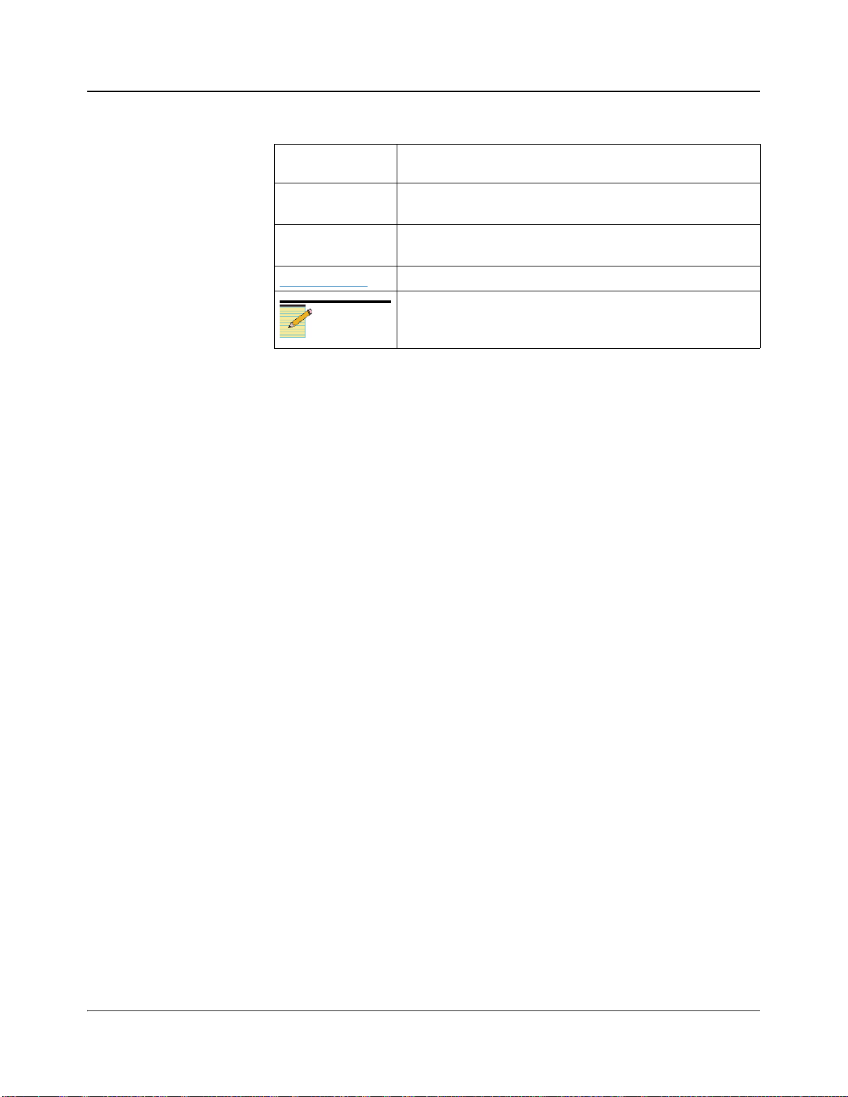
Table P-2. Writing Conventions (Continued)
Preface
Term or
Convention
> Indicates the direction of navigation through a hierarchy of
hyperlink Indicates a jump to another location within the electronic
Internet address
Obtaining Documents
Technical documents can be viewed or downloaded from our website.
Alternatively, contact your Customer Service representative to request a
document.
Note
Description
menus and windows
document or elsewhere
Indicates a jump to a Web site or URL
Indicates important information that helps to avoid and
troubleshoot problems
880 Series Audio Distribution Amplifiers Instruction Manual xi
Copyright © 2001-2004, 2006, 2008, Harris Corporation
Page 12

Preface
Unpacking/Shipping Information
Unpacking a Product
This product was carefully inspected, tested, and calibrated before shipment to
ensure years of stable and trouble-free service.
1. Check equipment for any visible damage that may have occurred during
transit.
2. Confirm that you have received all items listed on the packing list.
3. Contact your dealer if any item on the packing list is missing.
4. Contact the carrier if any item is damaged.
5. Remove all packaging material from the product and its associated
components before you install the unit.
Keep at least one set of original packaging, in the event that you need to return a
product for servicing.
Returning a Product
In the unlikely event that your product fails to operate properly, please contact
Customer Service to obtain a Return Authorization (RA) number, then send the
unit back for servicing.
Keep at least one set of original packaging in the event that a product needs to
be returned for service. If the original package is not available, you can supply
your own packaging as long as it meets the following criteria:
• The packaging must be able to withstand the product’s weight.
• The product must be held rigid within the packaging.
• There must be at least 2 in. (5 cm) of space between the product and the
container.
• The corners of the product must be protected.
Ship products back to us for servicing prepaid and, if possible, in the original
packaging material. If the product is still within the warranty period, we will
return the product prepaid after servicing.
xii 880 Series Audio Distribution Amplifiers Instruction Manual
Copyright © 2001-2004, 2006, 2008, Harris Corporation
Page 13

Standards
Appendix A: “Safety Precautions, Certifications, and Compliances” contains
product compliance and safety standards.
Restriction on Hazardous Substances (RoHS) Compliance
Directive 2002/95/EC—commonly known as the European Union (EU)
Restriction on Hazardous Substances (RoHS)—sets limits on the use of certain
substances found in electrical and electronic equipment. The intent of this
legislation is to reduce the amount of hazardous chemicals that may leach out of
landfill sites or otherwise contaminate the environment during end-of-life
recycling. The Directive, which took effect on July 1, 2006, refers to the
following hazardous substances:
• Lead (Pb)
• Mercury (Hg)
• Cadmium (Cd)
• Hexavalent Chromium (Cr-V1)
• Polybrominated Biphenyls (PBB)
Preface
• Polybrominated Diphenyl Ethers (PBDE)
According to this EU Directive, all products sold in the European Union will be
fully RoHS-compliant and “lead-free.” (See our website for more information
on dates and deadlines for compliance.) Spare parts supplied for the repair and
upgrade of equipment sold before July 1, 2006 are exempt from the legislation.
Equipment that complies with the EU directive will be marked with a
RoHS-compliant emblem, as shown in Figure P-1.
Figure P-1. RoHS Compliance Emblem
Waste from Electrical and Electronic Equipment (WEEE) Compliance
The European Union (EU) Directive 2002/96/EC on Waste from Electrical and
Electronic Equipment (WEEE) deals with the collection, treatment, recovery,
and recycling of electrical and electronic waste products. The objective of the
WEEE Directive is to assign the responsibility for the disposal of associated
hazardous waste to either the producers or users of these products. Effective
August 13, 2005, producers or users will be required to recycle electrical and
electronic equipment at end of its useful life, and may not dispose of the
equipment in landfills or by using other unapproved methods. (Some EU
member states may have different deadlines.)
880 Series Audio Distribution Amplifiers Instruction Manual xiii
Copyright © 2001-2004, 2006, 2008, Harris Corporation
Page 14

Preface
In accordance with this EU Directive, companies selling electric or electronic
devices in the EU will affix labels indicating that such products must be
properly recycled. (See our website for more information on dates and deadlines
for compliance.) Contact your local sales representative for information on
returning these products for recycling. Equipment that complies with the EU
directive will be marked with a WEEE-compliant emblem, as shown in Figure
P-2.
Figure P-2. WEEE Compliance Emblem
xiv 880 Series Audio Distribution Amplifiers Instruction Manual
Copyright © 2001-2004, 2006, 2008, Harris Corporation
Page 15
Safety
Carefully review all safety precautions to avoid injury and prevent damage to
this product or any products connected to it. You will find a complete list of
safety precautions in Appendix A. Any user-serviceable components (such as
fuses or batteries) are only replaceable by those components listed in the
manual.
IMPORTANT! Only qualified personnel should perform service procedures.
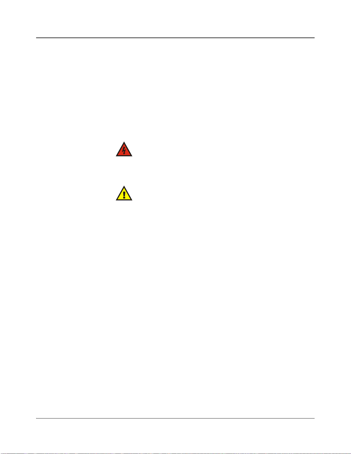
Safety Terms and Symbols in this Manual
WARNING
Statements identifying conditions or practices
that may result in personal injury or loss of life.
High voltage is present.
CAUTION
Statements identifying conditions or practices
that can result in damage to the equipment or
other property.
Preface
880 Series Audio Distribution Amplifiers Instruction Manual xv
Copyright © 2001-2004, 2006, 2008, Harris Corporation
Page 16

Preface
xvi 880 Series Audio Distribution Amplifiers Instruction Manual
Copyright © 2001-2004, 2006, 2008, Harris Corporation
Page 17

Preliminary—Contents are proprietary and confidential. Do not photocopy or distribute.
880 Series Mounting Frames
Overview
The 880 series, 8-output audio distribution amplifiers meet the most demanding
requirements for AM/FM/TV broadcast and program production systems.
Heading the list of the amplifier’s exceptional performance characteristics is the
100 dB S/N ratio. Flat frequency response, carefully controlled roll-off and very
low distortion ensure a virtually transparent transmission path.
The amplifier’s input is overvoltage protected up to 120 volts AC or DC. The
transformerless, balanced input is normally bridging, but can be terminated by
installing a suitable resistor. Unbalanced input is converted to balanced output.
Chapter 1
Isolation between modules in the mounting frame is better than 100 dB over the
entire audio frequency band.
The modular concept with two fully wired mounting frame options facilitates
system design. The options are as follows:
• The FR-883 and FR-884 mounting frames accept up to twelve 880 series
audio distribution amplifier modules.
• The FR-883 frame accepts one 884PS power supply, while the FR-884
frame accepts two 884PS power supplies. A fully loaded FR-884 frame will
operate with a single power supply; however, we recommend that a second
optional power supply be included for cooler operation and power
redundancy.
• The high efficiency, shielded switching power supply accepts line inputs
from 90 to 135 VAC without changing transformer taps.
880 Series Audio Distribution Amplifiers Instruction Manual 1
Copyright © 2001-2004, 2006, 2008, Harris Corporation
Page 18

Preliminary—Contents are proprietary and confidential. Do not photocopy or distribute.
Chapter 1: 880 Series Mounting Frames
Mounting Requirements
All Leitch equipment is carefully inspected and calibrated before shipment to
ensure years of stable and trouble-free service.
•Review “Unpacking/Shipping Information” on page xii in the Preface to
this manual.
• Inspect the equipment for any visible damage which may have occurred
during transit before installation.
• Make sure that all modules are properly seated in the mounting frame.
The mounting requirements of the 880 series frame options are as follows.
FR-883
The FR-883 mounting frame requires 1 unit of rack space: 1¾ in. (44 mm) high
× 19 in. (483 mm) wide × 11 in. (280 mm) deep. This frame can house 4
modules.
Figure 1-1. FR-883
Figure 1-2. FR-883 Back Panel
2 880 Series Audio Distribution Amplifiers Instruction Manual
Copyright © 2001-2004, 2006, 2008, Harris Corporation
Page 19

Preliminary—Contents are proprietary and confidential. Do not photocopy or distribute.
Chapter 1: 880 Series Mounting Frames
FR-884
The FR-884 mounting frame requires 2 units of rack space: 3½ in. (88 mm)
high × 19 in. (483 mm) wide × 11 in. (280 mm) deep. This frame can house 12
modules.
Figure 1-3. FR-884
Figure 1-4. FR-884 Back Panel
880 Series Audio Distribution Amplifiers Instruction Manual 3
Copyright © 2001-2004, 2006, 2008, Harris Corporation
Page 20

Preliminary—Contents are proprietary and confidential. Do not photocopy or distribute.
Chapter 1: 880 Series Mounting Frames
Frame Cooling
The equipment is designed to operate in an ambient temperature range of 32°F –
122°F (0°C – 50°C). No special cooling arrangements are necessary, but you
should take steps to prevent excessive ambient heat rise in closed, unventilated
equipment racks.
Power Consumption
The FR-883 mounting frame accepts one 884PS power supply. The FR-883
frame power consumption is nominally 25VA.
The FR-884 mounting frame accepts one 884PS power supply. The frame is
prewired to accept a second optional power supply for power backup. The
FR-884 frame power consumption is nominally 65VA. A fully loaded frame
will operate with a single power supply; however, we recommend that a second
optional power supply be included for cooler operation and power redundancy.
To prevent electric shock, do not use the (polarized)
plug with an extension cord, receptacle, or other outlet
unless the blades can be fully inserted to prevent blade
exposure.
4 880 Series Audio Distribution Amplifiers Instruction Manual
Copyright © 2001-2004, 2006, 2008, Harris Corporation
Page 21

Preliminary—Contents are proprietary and confidential. Do not photocopy or distribute.
Chapter 1: 880 Series Mounting Frames
884 PS Power Supply
The model 884PS power supply is a two-stage switching power supply that
provides that provides the following outputs:
• +21V at 1.0A
• –21V at 1.0A
Initial design criteria focused on maximizing efficiency and minimizing
individual component temperature rise. This has been achieved with a two stage
design consisting of an input “Buck” converter feeding a high efficiency
push-pull output stage. Overall efficiency exceeds 80% and individual
component temperature rise is minimized by operating both converts at high
voltage and low current as well as using Schottky rectifier diodes on the output
stage.
The power supply is designed to work over the two standard input voltage
ranges. With input selector switch S2 in the 110 position, the power supply
operates over and input range of 85 – 135VAC and with the switch in the 220
position the operating range is 170 – 270VAC. Output voltage is adjustable by
±10%. Other output voltages can be achieved by changing power transformer
TR1 without any additional circuit changes.
880 Series Audio Distribution Amplifiers Instruction Manual 5
Copyright © 2001-2004, 2006, 2008, Harris Corporation
Page 22

Preliminary—Contents are proprietary and confidential. Do not photocopy or distribute.
Chapter 1: 880 Series Mounting Frames
Cable Harness Support Bracket
The cable support bracket is made up of three parts:
• 1 right side bracket
• 1 left side bracket
• 1 cable support bar
The brackets screw to the back of the frame using an existing black screw. The
screw is in the vertical center of the frame, 1¼ inches forward of the back edge.
There is one screw on the right side of the frame at the very back of the frame.
This screw is not removed. A clearance hole in the bracket will fit over this
screw. There are two holes in the side of the brackets. The bottom of the bracket
sits on the top edge of the bottom of the frame. Remove the screw from the side
of the frame, place the bracket and replace the screw. Mount the cable support
bar with a 6-32 x 3/8-inch binder head screw to each bracket.
6 880 Series Audio Distribution Amplifiers Instruction Manual
Copyright © 2001-2004, 2006, 2008, Harris Corporation
Page 23

Preliminary—Contents are proprietary and confidential. Do not photocopy or distribute.
Chapter 1: 880 Series Mounting Frames
Back Panel Pinout Assignments
Figure 1-5. FR-883 Back Panel Pinout Assignments
Figure 1-6. FR-884 and FR-684-AV Balanced Audio Back Panel Pinout Assignments
880 Series Audio Distribution Amplifiers Instruction Manual 7
Copyright © 2001-2004, 2006, 2008, Harris Corporation
Page 24

Preliminary—Contents are proprietary and confidential. Do not photocopy or distribute.
Chapter 1: 880 Series Mounting Frames
Back Panel Connections
Table 1-1. AMD-880; APD-880, ASD-880, and ATG-880 (dBm) Back Panel Connectors for FR-883
and FR-884 Mounting Frames
AMD-880 APD-880-1 APD-880-2 ARG-880 ASD-880 ATG-880 (dBm)
Mono Stereo Mono
1A IN A IN IN IN A IN
2A 1 A1 1 A1
3A 2 A2 2 1 A2 +8
4A 3 A3 3 2 A3 +8
5A 4 A4 4 3 A4 +4
1B IN 4 B IN +4
2B 5 B1 5 5 B1 0
3B 6 B2 6 6 B2 0
4B 7 B3 7 7 B3 –10
5B 8 B4 8 Remote Ctrl B4 –10
Mono/ Remote
Gain
Stereo Test
8 880 Series Audio Distribution Amplifiers Instruction Manual
Copyright © 2001-2004, 2006, 2008, Harris Corporation
Page 25

Preliminary—Contents are proprietary and confidential. Do not photocopy or distribute.
AMD-880 Mono Audio Distribution
Amplifier Module
Overview
The AMD-880 mono audio distribution amplifier is designed to meet the most
demanding requirements of broadcast facilities, television post-production, and
recording studios. This excellent amplifier provides one high performance
channel with eight balanced outputs. Outputs can be customized to low (66Ω),
as per AES recommendation 1708 (I-3), or 600Ω impedance. Future impedance
modifications are also possible, should requirements change. Excellent output
isolation and interchannel crosstalk is assured by the individual drivers for each
output.
The input is overvoltage-protected up to 120 volts AC or DC. The
transformerless, balanced input is normally bridging, but can be terminated by
installing a suitable resistor. Unbalanced input is converted to balanced output.
The AMD-880 exceptional performance features include 100 dB S/N ratio, flat
frequency response, carefully controlled roll-off and very low distortion, thus
ensuring a virtually transparent transmission path. The extended shaft option
allows for front panel gain control in the FR-883 and FR-884 mounting frames.
Chapter 2
880 Series Audio Distribution Amplifiers Instruction Manual 9
Copyright © 2001-2004, 2006, 2008, Harris Corporation
Page 26

Preliminary—Contents are proprietary and confidential. Do not photocopy or distribute.
Chapter 2: AMD-880 Mono Audio Distribution Amplifier Module
10 880 Series Audio Distribution Amplifiers Instruction Manual
Copyright © 2001-2004, 2006, 2008, Harris Corporation
Page 27

Preliminary—Contents are proprietary and confidential. Do not photocopy or distribute.
Chapter 3
APD-880 Programmable Audio Distribution
Amplifier Module
Overview
The APD-880 mono/stereo programmable audio distribution amplifier has the
capability to provide many types of outputs simultaneously. Output signal types
are determined by the use of a removable sub-module. Several formats are
available that allow this module to replace any Leitch audio amplifier to date.
• APD-880-1 — Stereo in, 4 stereo out (Figure 3-2 on page 12)
• APD-880-2 — Mono in, 8 mono out (Figure 3-3 on page 12)
880 Series Audio Distribution Amplifiers Instruction Manual 11
Copyright © 2001-2004, 2006, 2008, Harris Corporation
Page 28

Preliminary—Contents are proprietary and confidential. Do not photocopy or distribute.
Chapter 3: APD-880 Programmable Audio Distribution Amplifier Module
Configuring an APD-880-0
1. Remove the cover from the APD-880-0
module.
2. Wire the selected configuration as shown in
the following wiring diagrams for each
version.
Figure 3-1. ADP-880-0 Module
Figure 3-2. APD-880-1 — Stereo in, 4 stereo out Figure 3-3. APD-880-2 — Mono in, 8 mono out
12 880 Series Audio Distribution Amplifiers Instruction Manual
Copyright © 2001-2004, 2006, 2008, Harris Corporation
Page 29

Preliminary—Contents are proprietary and confidential. Do not photocopy or distribute.
Chapter 4
ARG-880 Audio Remote Gain Distribution
Amplifier Module
Overview
The ARG-880 audio remote gain distribution amplifier is a high performance
amplifier that offers a ± 20dB remotely controlled audio gain that can be
increased for specific applications. Control is selectable to either remote or
local. Flat frequency response, carefully controlled roll-off and very low
distortion ensure a virtually transparent transmission path.
The input is overvoltage-protected up to 120 volts AC or DC. The
transformerless, balanced input IDs normally bridging, but can be terminated by
installing a suitable resistor. Unbalanced input is converted to balanced output.
Isolation between modules in the mounting frame is better than 90dB over the
entire audio frequency band.
880 Series Audio Distribution Amplifiers Instruction Manual 13
Copyright © 2001-2004, 2006, 2008, Harris Corporation
Page 30

Preliminary—Contents are proprietary and confidential. Do not photocopy or distribute.
Chapter 4: ARG-880 Audio Remote Gain Distribution Amplifier Module
Remote Control Information
The remote control for the ARG-880 is a 0 to 5 VDC signal sent to the
ARG-880 module from a potentiometer (10kΩ) located at a remote location.
Ground reference and +5VDC source are located at connection 5B on the
FR-883 and FR-884 frames. The actual remote connection is as follows:
Figure 4-1. Remote Connections
14 880 Series Audio Distribution Amplifiers Instruction Manual
Copyright © 2001-2004, 2006, 2008, Harris Corporation
Page 31

Preliminary—Contents are proprietary and confidential. Do not photocopy or distribute.
ASD-880 Stereo Audio Distribution
Amplifier Module
Overview
The ASD-880 stereo audio distribution amplifier is designed to meet the most
demanding requirements of broadcast facilities, television post-production, and
recording studios. This excellent amplifier provides one high performance
channel with eight balanced outputs. Outputs can be customized to low (66Ω),
as per AES recommendation 1708 (I-3), or 600Ω impedance. Future impedance
modifications are also possible, should requirements change. Excellent output
isolation and interchannel crosstalk is assured by the individual drivers for each
output.
The input is overvoltage-protected up to 120 volts AC or DC. The
transformerless, balanced input is normally bridging, but can be terminated by
installing a suitable resistor. Unbalanced input is converted to balanced output.
The ASD-880 exceptional performance features include 100 dB S/N ratio, flat
frequency response, carefully controlled roll-off and very low distortion, thus
ensuring a virtually transparent transmission path. The extended shaft option
allows for front panel gain control in the FR-883 and FR-884 mounting frames.
Chapter 5
880 Series Audio Distribution Amplifiers Instruction Manual 15
Copyright © 2001-2004, 2006, 2008, Harris Corporation
Page 32

Preliminary—Contents are proprietary and confidential. Do not photocopy or distribute.
Chapter 5: ASD-880 Stereo Audio Distribution Amplifier Module
16 880 Series Audio Distribution Amplifiers Instruction Manual
Copyright © 2001-2004, 2006, 2008, Harris Corporation
Page 33

Preliminary—Contents are proprietary and confidential. Do not photocopy or distribute.
ATG-880 Audio Tone
Generator Module
Overview
The ATG-880 is a low distortion audio tone generator with high level-stability.
The module provides 8 outputs, that is, four pairs of outputs, each pair being at a
different level. One output of each pair can be pulsed off and on at a rate of
about once per second.
Chapter 6
The basic tone generator is a Wien-bridge oscillator, chosen for its inherent low
distortion. The bridge consists of the RC network at pins 14 and 12 of IC4D and
ground. The network contains two arms. The top arm is series resonant at
400Hz when the switch is open and 1000Hz when closed. Similarly, the bottom
arm is parallel resonant at 400Hz when the switch is open and 1000Hz when
closed. At resonance, the voltage at pin 12 of IC4D is at a maximum with
respect to the voltage of pin 14 while the relative phase angle is zero. In order to
sustain steady oscillation, IC4D must be maintained at a gain of 3. This is
achieved by means of the circuit consisting of IC4A, IC4B, IC4C and IC1A.
The output from pin 14 of IC4D is amplified to a gain of 4 by inverting
amplifier IC4A. Its output at pin 1 is AC coupled through a 68 μF capacitor and
diverted to two places, that is, the control loop and the output stage later
described.
880 Series Audio Distribution Amplifiers Instruction Manual 17
Copyright © 2001-2004, 2006, 2008, Harris Corporation
Page 34

Preliminary—Contents are proprietary and confidential. Do not photocopy or distribute.
Chapter 6: ATG-880 Audio Tone Generator Module
Control Loop
The control loop converts the signal to a DC voltage proportional to its level by
means of the full-wave rectifier and integrator consisting of IC4B and IC4C.
During the positive half cycle, pin 7 of IC4B goes low, turning on diode D4 and
thus, holding pin 7 to zero volts. As pin 6 of IC4B and pin 9 of IC4C are also at
virtual ground level, the cathode of diode D5 is also zero volts. During the
negative half cycles, pin 7 of IC4B goes high, turning on diode D5 and off diode
D4, thus causing negative half cycles of equal but inverted amplitude to appear
at the cathode of diode D5. This signal is combined with the original in a two to
one ratio by summing amplifier/ integrator IC4C. The resultant DC voltage at
pin 8 of IC4C is proportional to the peak voltage of the oscillator.
The negative DC voltage from Zener diode IC7 is also added at the summing
point of IC4C at pin 9 through the 20K LEVEL trimpot to adjust the signal
amplitude.
The positive DC voltage at pin 8 of IC4C biases the anode of diode D1 through
a 4.7k resistor and the cathode of D2 through voltage inverter IC1A and a 4.7k
resistor. The bias current controls the dynamic resistance of diodes D1 and D2,
thereby controlling the net resistance from pin 13 of IC4D to ground and thus,
maintaining the gain of IC4D at 3.
Output Stage
The output stage accepts the signal from the 68 μF capacitor and converts it to a
balanced signal by means of buffer IC1C and inverter IC1B.
The signal from pins 7 and 8 of IC1 is taken directly to output drivers IC3A,
IC3B, IC3C and IC3D which buffer the 8 dBm Outputs 1 and 2. Each
subsequent output pair is taken from pins 7 and 8 of IC1 trough a resistive
network that attenuates the signal to the desired levels before being buffered by
their corresponding output drivers. The outputs numbered 2, 4, 6 and 8,
representing the left channel of each output pair, are bridged prior to the output
driver by analog switch IC8 and a pair of 100k resistors. A high level on the
control line of the analog switches will cause them to close and turn off the left
channel of each pair. Closing the IDENT switch will enable multivibrator IC2
and thus cause the left channel of each pair to be pulsed off and on at about once
per second.
18 880 Series Audio Distribution Amplifiers Instruction Manual
Copyright © 2001-2004, 2006, 2008, Harris Corporation
Page 35

Preliminary—Contents are proprietary and confidential. Do not photocopy or distribute.
884PS Power Supply Module
Overview
The model 884PS power supply is a two stage switching power supply that
provides the following outputs:
• + 21 V@ 1.0 A
• – 21 V @ 1.0 A
Chapter 7
Initial design criteria focused on maximizing efficiency and minimizing
individual component temperature rise. This has been achieved with a two stage
design consisting of an input “Buck” converter feeding a high-efficiency.
push-pull output stage. Overall efficiency exceeds 80% and individual
component temperature rise is minimized by operating both converts at high
voltage and low current as well as using Schottky rectifier diodes on the output
stage. The power supply operates over an input range of 85-135 VAC when
input selector switch S2 is in the 110 position, and when the switch is in the 220
position the operating range is 170-270 VAC.
Output voltage is adjustable by ±10%. Other output voltages can be achieved by
changing power transformer TR1 without any additional circuit changes.
880 Series Audio Distribution Amplifiers Instruction Manual 19
Copyright © 2001-2004, 2006, 2008, Harris Corporation
Page 36

Preliminary—Contents are proprietary and confidential. Do not photocopy or distribute.
Chapter 7: 884PS Power Supply Module
Installing the 884PS-48
Precautions
WARNING: To reduce the risk of electric shock or energy hazards
• Connect the 884PS to a reliably grounded SELV source or a centralized DC source.
• Make sure the branch circuit overcurrent protection is rated a maximum 15A circuit breaker in
series with a maximum 5A listed fuse. (See “Suggested Protection Devices” on page 21.)
• Use 14 AWG solid copper conductors only.
• Incorporate a readily accessible, suitably approved, and suitably rated disconnect device into the
field wiring. (See “Suggested breaker switch type” on page 21.)
• Install the 884PS in a restricted access area in accordance with the NEC or the authority having
jurisdiction.
WARNING: To reduce the risk of electric shock
• Perform installation and exchange only you are a trained technician who is familiar with these
instructions and aware of the shock hazards of working with live equipment.
• Install the 884PS-48 power supply in accordance with the schematic diagram shown in
Figure 7-1. Power can only be disconnected completely from the 880 series frame through a
studio installed breaker or fuse.
20 880 Series Audio Distribution Amplifiers Instruction Manual
Copyright © 2001-2004, 2006, 2008, Harris Corporation
Page 37

Preliminary—Contents are proprietary and confidential. Do not photocopy or distribute.
Chapter 7: 884PS Power Supply Module
Branch Circuit Schematic
The 884PS-48 power supply differs from other Leitch power supplies in that it
depends on the studio’s installed circuit breaker/fuse to disconnect power to the
frame.
Figure 7-1. Typical Branch Circuit Drawing
Suggested Protection Devices
Suggested breaker switch type Eaton Heinemann®, series AM/S*, part no.
Suggested branch circuit fuse type Buss® part no. GMT-5† or equivalent
B
* “Heinemann” is a registered trademark of Eaton Corporation, Cleveland, Ohio. The AM/S series are
products of Eaton Corporation.
† “Buss” is a registered trademark of Cooper Bussman, St. Louis, Missouri.
M1S-B2-A-A-02J-H-A-52-NO-10-10 or
equivalent
880 Series Audio Distribution Amplifiers Instruction Manual 21
Copyright © 2001-2004, 2006, 2008, Harris Corporation
Page 38

Preliminary—Contents are proprietary and confidential. Do not photocopy or distribute.
Chapter 7: 884PS Power Supply Module
Maintaining the 884PS-48
Power Supply Replacement Fuse Information
WARNING: For continued protection against fire,
replace only with the same type and rating of fuse.
The replacement fuse (F1) for the 884PS-48 is a Wickmann 19194-2.5A, 250V
fuse. This replacement fuse is a product of Wickmann-Werke, Witten, Germany.
Power Supply Connections
Use the XLR connector at the back of the power supply or frame (if the
884PS-48 is installed in a frame) to make the following pin connections for the
884PS-48.
Figure 7-2. XLR Connector
Pin Number Connection
1 –48 V
20 V
3 Chassis
Specifications
Specifications: 884PS-48
Input 42–60 VDC 1.5A
50 VA maximum
22 880 Series Audio Distribution Amplifiers Instruction Manual
Copyright © 2001-2004, 2006, 2008, Harris Corporation
Page 39

Preliminary—Contents are proprietary and confidential. Do not photocopy or distribute.
Specifications
Overview
Specifications and designs are subject to change without notice.
The following specification tables appear in this chapter:
• Electrical
Chapter 8
• Mechanical
• Input
•Output
• Performance
880 Series Audio Distribution Amplifiers Instruction Manual 23
Copyright © 2001-2004, 2006, 2008, Harris Corporation
Page 40

Preliminary—Contents are proprietary and confidential. Do not photocopy or distribute.
Chapter 8: Specifications
FR-883 / FR-884 Mounting Frames
Electrical
Table 8-1. FR-883 / FR-884 Mounting Frame Electrical Specifications
Item Specification
Voltage 90 – 135 VAC
Frequency 50/60 Hz
Power 65 VA max. (fully loaded)
Mechanical
Table 8-2. FR-883 / FR-884 Mounting Frame Mechanical Specifications
Item Specification
Height 3½ in. (88 mm)
Width 19 in. (483 mm)
Depth from mounting surface 11 in. (280 mm)
Nominal weight (with modules) 19.6 lb (8.9 kg)
24 880 Series Audio Distribution Amplifiers Instruction Manual
Copyright © 2001-2004, 2006, 2008, Harris Corporation
Page 41

Preliminary—Contents are proprietary and confidential. Do not photocopy or distribute.
Chapter 8: Specifications
AMD-880 Mono Audio Distribution Amplifier Module
Input
Table 8-3. AMD-880 Input Specifications
Item Specification
Impedance > 30KΩ, balanced
Max. level +30 dBu
Common mode range ± 20 volts
Common mode rejection > 90 dB @ 60 Hz
> 60 dB @ 20 kHz
Output
Performance
Table 8-4. AMD-880 Output Specifications
Item Specification
Number of outputs 8
Impedance Low impedance (66Ω, balanced)
Max. level +30 dBu
Output to output isolation > 70 dB 20 Hz to 20 kHz
Table 8-5. AMD-880 Performance Specifications
Item Specification
Gain range – 6 to +33 dB
(± 6 dB on 18-turn pot, 0, +9, +18, +27
dB on jumper)
Signal to noise > 100 dB @ unity gain
20 Hz – 20 kHz, relative to +8 dBu signal,
unweighted
Frequency response < ± 0.05 dB, 20 Hz – 20 kHz, relative to 1
kHz, any level up to +30 dBu
Total harmonic distortion < 0.02%, 20 Hz – 20 kHz @ +30 dBu
Intermodulation distortion < 0.01% SMPTE @ +18 dBu
< 0.02% SMPTE @ +24 dBu
Isolation between modules > 100 dB, 20 Hz – 20 kHz
Temperature range 41°– 104°F (5°– 40°C)
880 Series Audio Distribution Amplifiers Instruction Manual 25
Copyright © 2001-2004, 2006, 2008, Harris Corporation
Page 42

Preliminary—Contents are proprietary and confidential. Do not photocopy or distribute.
Chapter 8: Specifications
AMD-880 Mono Audio Distribution Amplifier
Module (600Ω Impedance)
Input
Table 8-6. AMD-880 (600Ω Impedance) Input Specifications
Item Specification
Impedance > 30 kΩ, balanced
Max. level +30 dBm
Common mode range ± 20 volts
Common mode rejection > 90 dB @ 60 Hz
> 60 dB @ 20 kHz
Output
Performance
Table 8-7. AMD-880 (600Ω Impedance) Output Specifications
Item Specification
Number of outputs 8
Impedance 600 Ω balanced
Max. level +24 dBm
Output to output isolation > 70 dB 20 Hz to 20 kHz
Table 8-8. AMD-880 (600Ω Impedance) Performance Specifications
Item Specification
Gain range – 6 to +33 dB
(± 6 dB on 18-turn pot, 0, +9, +18, +27
dB on jumper)
S/N ratio > 100 dB @ unity gain
20 Hz – 20 kHz, relative to +8 dBm
signal, unweighted
Frequency response < ± 0.05 dB, 20 Hz – 20 kHz, rel. to 1
kHz, any level up to +24 dBm
Total harmonic distortion < 0.05%, 20 Hz – 20 kHz @ +24 dBm
Intermodulation distortion < 0.02% SMPTE @ +18 dBm
Isolation between modules > 100 dB, 20 Hz – 20 kHz
Temperature range 41°– 104°F (5°– 40°C)
26 880 Series Audio Distribution Amplifiers Instruction Manual
Copyright © 2001-2004, 2006, 2008, Harris Corporation
Page 43

Preliminary—Contents are proprietary and confidential. Do not photocopy or distribute.
Chapter 8: Specifications
APD-880 Programmable Audio Distribution Amplifier Module
Input
Table 8-9. APD-880 Input Specifications
Item Specification
Impedance > 30KΩ, balanced
Max. level +30 dBu
Common mode range ± 20 volts
Common mode rejection > 90 dB @ 60 Hz
> 60 dB @ 20 kHz
Output
Performance
Table 8-10. APD-880 Output Specifications
Item Specification
Channels 2
Outputs per channel 4
Impedance Low impedance (66Ω, balanced)
Max. level +30 dBu
Output to output isolation > 70 dB 20 Hz to 20 kHz
Table 8-11. APD-880 Performance Specifications
Item Specification
Gain range – 6 to +33 dB
± 6 dB on 18-turn pot, 0, +9, +18, +27 dB on jumper)
Signal to noise > 100 dB @ unity gain
20 Hz – 20 kHz, relative to +8 dBu signal,
unweighted
Frequency response < ± 0.05 dB, 20 Hz – 20 kHz, relative to 1 kHz, any
level up to +30 dBu
Total harmonic distortion < 0.02%, 20 Hz – 20 kHz @ +30 dBu
Intermodulation distortion < 0.01% SMPTE @ +18 dBu
< 0.02% SMPTE @ +24 dBu
Isolation between modules > 100 dB, 20 Hz – 20 kHz
Interchannel crosstalk > 95 dB, 20 Hz – 20 kHz
Temperature range 41°– 104°F (5°– 40°C)
880 Series Audio Distribution Amplifiers Instruction Manual 27
Copyright © 2001-2004, 2006, 2008, Harris Corporation
Page 44

Preliminary—Contents are proprietary and confidential. Do not photocopy or distribute.
Chapter 8: Specifications
APD-880 Programmable Audio Distribution
Amplifier Module (600Ω Impedance)
Input
Table 8-12. APD-880 (600Ω Impedance) Input Specifications
Item Specification
Impedance > 30 kΩ, balanced
Max. level +30 dBm
Common mode range ± 20 volts
Common mode rejection > 90 dB @ 60 Hz
> 60 dB @ 20 kHz
Output
Performance
Table 8-13. APD-880 (600Ω Impedance) Output Specifications
Item Specification
Channels 2
Outputs per channel 4
Impedance 600Ω balanced
Max. level +24 dBm
Output to output isolation > 70 dB 20 Hz to 20 kHz
Table 8-14. APD-880 (600Ω Impedance) Performance Specifications
Item Specification
Gain range – 6 to +33 dB
(± 6 dB on 18-turn pot,0, +9, +18, +27 dB
on jumper)
S/N ratio > 100 dB @ unity gain 20 Hz – 20 kHz,
relative to +8 dBm signal, unweighted
Frequency response < ± 0.05 dB 20 Hz – 20 kHz, rel. to 1
kHz, any level up to +24 dBm
Total harmonic distortion < 0.05%, 20 Hz – 20 kHz @ +24 dBm
Intermodulation distortion < 0.02% SMPTE @ +18 dBm
Isolation between modules > 100 dB, 20 Hz – 20 kHz
Interchannel crosstalk > 95 dB, 20 Hz – 20 kHz
Temperature range 41°– 104°F (5°– 40°C)
28 880 Series Audio Distribution Amplifiers Instruction Manual
Copyright © 2001-2004, 2006, 2008, Harris Corporation
Page 45

Preliminary—Contents are proprietary and confidential. Do not photocopy or distribute.
Chapter 8: Specifications
ARG-880 Audio Remote Gain Distribution Amplifier Module
Input
Table 8-15. ARG-880 Input Specifications
Item Specification
Impedance > 50KΩ, balanced
Max. level +30 dBm
Common mode range ± 20 volts
Common mode rejection > 90 dB @ 60 Hz, > 60 dB @ 20 kHz
Output
Performance
Table 8-16. ARG-880 Output Specifications
Item Specification
Number of outputs 7
Impedance 600Ω, balanced
Max. level +24 dBm
Output to output isolation >70 dB 20 Hz to 20 kHz
Table 8-17. ARG-880 Performance Specifications
Item Specification
Gain range – 20 to +20 dB
Signal to noise > 100 dB @ unity gain
20 Hz – 20 kHz, relative to +8 dBm
signal, unweighted
Frequency response < ± 0.05 dB, 20 Hz – 20 kHz, relative to 1
kHz, any level up to +24 dBm
Total harmonic distortion < 0.02%, 20 Hz – 20 kHz @ +24 dBm, all
outputs loaded
Intermodulation distortion < 0.01% SMPTE @ +18 dBm
< 0.02% SMPTE @ +24 dBm
Isolation between modules > 100 dB, 20 Hz – 20 kHz
Temperature range 41°– 104°F (5°– 40°C)
Control input 0 to 5V DC
+5V DC provided as output
880 Series Audio Distribution Amplifiers Instruction Manual 29
Copyright © 2001-2004, 2006, 2008, Harris Corporation
Page 46

Preliminary—Contents are proprietary and confidential. Do not photocopy or distribute.
Chapter 8: Specifications
ASD-880 Stereo Audio Distribution Amplifier Module
Input
Table 8-18. ASD-880 Input Specifications
Item Specification
Impedance > 30KΩ, balanced
Max. level +30 dBu
Common mode range ± 20 volts
Common mode rejection > 90 dB @ 60 Hz, > 60 dB @ 20 kHz
Output
Performance
Table 8-19. ASD-880 Output Specifications
Item Specification
Channels 2
Outputs per channel 4
Impedance Low impedance (66Ω, balanced)
Max. level +30 dBu
Output to output isolation > 70 dB 20 Hz to 20 kHz
Table 8-20. ASD-880 Performance Specifications
Item Specification
Gain range – 6 to +33 dB
(± 6 dB on 18-turn pot, 0, +9, +18, +27
dB on jumper)
Signal to noise > 100 dB @ unity gain
20 Hz – 20 kHz, relative to +8 dBu signal,
unweighted
Frequency response ± 0.05 dB, 20 Hz – 20 kHz, relative to 1
kHz, any level up to +30 dBu
Total harmonic distortion < 0.02%, 20 Hz – 20 kHz @ +30 dBu
Intermodulation distortion < 0.01% SMPTE @ +18 dBu
< 0.02% SMPTE @ +24 dBu
Isolation between modules > 100 dB, 20 Hz – 20 kHz
Interchannel crosstalk > 95 dB, 20 Hz – 20 kHz
Temperature range 41°– 104°F (5°– 40°C)
30 880 Series Audio Distribution Amplifiers Instruction Manual
Copyright © 2001-2004, 2006, 2008, Harris Corporation
Page 47

Preliminary—Contents are proprietary and confidential. Do not photocopy or distribute.
Chapter 8: Specifications
ASD-880 Stereo Audio Distribution Amplifier
Module (600Ω Impedance)
Input
Table 8-21. ASD-880 (600Ω Impedance) Input Specifications
Item Specification
Impedance > 30 kΩ, balanced
Max. level +30 dBm
Common mode range ± 20 volts
Common mode rejection > 90 dB @ 60 Hz
> 60 dB @ 20 kHz
Output
Performance
Table 8-22. ASD-880 (600Ω Impedance) Output Specifications
Item Specification
Channels 2
Outputs per channel 4
Impedance 600 Ω balanced
Max. level +24 dBm
Output to output isolation > 70 dB 20 Hz to 20 kHz
Table 8-23. ASD-880 (600Ω Impedance) Performance Specifications
Item Specification
Gain range – 6 to +33 dB
(± 6 dB on 18-turn pot, 0, +9, +18, +27
dB on jumper)
S/N ratio > 100 dB @ unity gain 20 Hz – 20 kHz,
relative to +8 dBm signal, unweighted
Frequency response < ± 0.05 dB 20 Hz – 20 kHz, rel. to 1
kHz, any level up to +24 dBm
Total harmonic distortion < 0.05%, 20 Hz – 20 kHz @ +24 dBm
Intermodulation distortion < 0.02% SMPTE @ +18 dBm
Isolation between modules > 100 dB, 20 Hz – 20 kHz
Interchannel crosstalk > 95 dB, 20 Hz – 20 kHz
Temperature range 41°– 104°F (5°– 40°C)
880 Series Audio Distribution Amplifiers Instruction Manual 31
Copyright © 2001-2004, 2006, 2008, Harris Corporation
Page 48

Preliminary—Contents are proprietary and confidential. Do not photocopy or distribute.
Chapter 8: Specifications
ATG-880 Audio Tone Generator Module
Table 8-24. ATG-880 Specifications
Item Specification
Frequencies 400/1000 Hz, switchable
Frequency option 440 Hz on request
Frequency accuracy < ± 1%
Number of outputs 8
Output levels + 8 dBm (2 outputs)
+ 4 dBm (2 outputs)
0 dBm (2 outputs)
–10 dBm (2 outputs)
Output level accuracy < ± 0.05 dB (all outputs relative to +8
dBm output)
Output level stability < 0.1 dB
Total harmonic distortion <0.1%, all outputs
Output impedance 600Ω, balanced
Temperature range 32°– 122°F (0° – 50° C)
32 880 Series Audio Distribution Amplifiers Instruction Manual
Copyright © 2001-2004, 2006, 2008, Harris Corporation
Page 49

Preliminary—Contents are proprietary and confidential. Do not photocopy or distribute.
Appendix A
Safety Precautions, Certifications, and
Compliances
Overview
Carefully observe the safety alert symbols below for dangers, warnings, and
cautions. They alert installers and operators of possible dangers or important
information contained in this manual.
Keep in mind, though, that warnings alone do not eliminate hazards, nor are
they a substitute for safe operating techniques and proper accident prevention
measures.
Any user-serviceable components (such as fuses or batteries) are only
replaceable by those components listed in the manual.
IMPORTANT! Only qualified personnel should perform service procedures.
880 Series Audio Distribution Amplifiers Instruction Manual 33
Copyright © 2001-2004, 2006, 2008, Harris Corporation
Page 50

Preliminary—Contents are proprietary and confidential. Do not photocopy or distribute.
Appendix A: Safety Precautions, Certifications, and Compliances
Safety Terms and Symbols in this Manual
WARNING
Statements identifying conditions or practices that may
result in personal injury or loss of life. High voltage is
present.
CAUTION
Statements identifying conditions or practices that can result in
damage to the equipment or other property.
Safety Terms and Symbols on the Product
DANGER: High voltage and indicates a personal injury
hazard immediately accessible as one reads the
marking.
WARNING: Indicates a personal injury hazard not
immediately accessible as one reads the marking.
CAUTION: Indicates a hazard to property, including the
product, or to pay attention and refer to the manual.
Protective ground (earth) terminal.
Fuse. Replace with same type and rating of fuse.
Zur Vermeidung von Feuer verwenden Sie nur Sicherungen mit der für
dieses Produkt geforderten Typ und Stromstärke.
34 880 Series Audio Distribution Amplifiers Instruction Manual
Copyright © 2001-2004, 2006, 2008, Harris Corporation
Page 51

Preliminary—Contents are proprietary and confidential. Do not photocopy or distribute.
Appendix A: Safety Precautions, Certifications, and Compliances
Preventing Electrostatic Discharge
Observe precautions for handling electrostatic sensitive devices.
CAUTION: Electrostatic discharge (ESD) can damage
components in the product. To prevent ESD, observe these
precautions when directed to do so:
1. Use a Ground Strap. Wear a grounded antistatic wrist strap to
discharge the static voltage from your body while installing or
removing sensitive components.
2. Use a Safe Work Area. Do not use any devices capable of generating or
holding a static charge in the work area where you install or remove
sensitive components. Avoid handling sensitive components in areas
that have a floor or benchtop surface capable of generating a static
charge.
3. Handle Components Carefully. Do not slide sensitive components
over any surface. Do not touch exposed connector pins. Handle
sensitive components as little as possible.
4. Transport and Store Carefully. Transport and store sensitive
components in a static-protected bag or container.
Injury Precautions
WARNING
Potentially lethal voltages are present within the frame
during normal operation. The AC power cord must be
disconnected from the frame before the top panel is
removed. (In frames with multiple power supplies,
remove ALL power cords.) Power should not be applied
to the frame while the top is open unless properly
trained personnel are servicing the unit.
Pull out the plug from the main socket before the
removal of a cover.
Przod zdjeciem pokrywy wyciagnac wtyczke z gniazda
sieciowego.
WARNING: SHOCK HAZARD - DO NOT OPEN.
AVIS: RISQUE DE CHOC ÉLECTRIQUE - NE PAS OUVRIR.
MOUNT IN RACK ONLY
INSTALLER SUR SUPPORT DE MONTAGE SEULEMENT.
USE PROPER POWER CORD
To avoid fire hazard, use only the power cord specified
for this product.
880 Series Audio Distribution Amplifiers Instruction Manual 35
Copyright © 2001-2004, 2006, 2008, Harris Corporation
Page 52

Preliminary—Contents are proprietary and confidential. Do not photocopy or distribute.
Appendix A: Safety Precautions, Certifications, and Compliances
GROUND THE PRODUCT
This is a Safety Class 1 product and is grounded through the grounding
conductor of the power cord. To avoid electrical shock, the grounding
conductor must be connected to earth ground. Before making connections to
the product’s input or output terminals, ensure the product is properly
grounded.
WARNING: THIS APPLIANCE MUST BE GROUNDED.
WARNING: THIS APPLIANCE MUST BE EARTHED.
VARNING: APPARATEN SKALL ANSLUTAS TILL JORDAT
UTTAG NÄR DEN ANSLUTS TILL ETT NÄTVERK.
DO NOT OPERATE WITHOUT COVERS
To avoid electrical shock or fire hazard, do not operate
this product with covers or panels removed.
USE PROPER FUSE
To avoid fire hazard, use only the fuse type and rating
specified for this product.
DO NOT OPERATE IN WET/DAMP CONDITIONS
To avoid injury or fire hazard, do not operate this
product in wet or damp conditions.
DO NOT OPERATE IN AN EXPLOSIVE ATMOSPHERE
To avoid injury or fire hazard, do not operate this
product in an explosive atmosphere.
AVOID EXPOSED CIRCUITRY
To avoid injury, remove jewelry such as rings, watches,
and other metallic objects. Do not touch exposed
connections and components when power is present.
Product Damage Precautions
CAUTION: Disconnect power from the frame before
removing or installing input/ output modules.
Removing or installing modules with power applied
could cause serious damage to system components.
USE PROPER POWER SOURCE
Do not operate this product from a power source that supplies
more than the specified voltage.
36 880 Series Audio Distribution Amplifiers Instruction Manual
Copyright © 2001-2004, 2006, 2008, Harris Corporation
Page 53

Preliminary—Contents are proprietary and confidential. Do not photocopy or distribute.
Appendix A: Safety Precautions, Certifications, and Compliances
USE PROPER VOLTAGE SETTINGS
Before applying power, ensure that the line selector is in the
proper position for the power source being used.
PROVIDE PROPER VENTILATION
To prevent product overheating, provide proper ventilation.
DO NOT OPERATE WITH SUSPECTED FAILURES
If you suspect there is damage to this product, have it
inspected by qualified service personnel.
CAUTION: This unit can have more than one power supply
cord. To de-energize the internal circuitry, you have to
disconnect all power cords.
ADVARSEL: Utstyret kan ha mere ennn en tilførselsledning.
For å gjore interne deler spennigsløse må alle
tilførselsledningene trekkes ut.
VARNING: Denna apparat har mer än en nätanslutning.
Samtliga nätkablar måste bortkopplas för att göra de interna
kretsarna spänningsfria.
Fuse: Replace with same type and rating of fuse.
Caution: Replace with same type fuse.
Attention: Utiliser un fusible de rechange de même type.
Caution: Disconnect supply cord before changing fuse.
Attention: Débrancher avant de remplacer le fusible.
Achtung: Vor auswechseln der sicherung ist das gerät vom netz zu
trennen.
CAUTION: Disconnect power from the frame before
removing or installing input/ output modules. Removing or
installing modules with power applied could cause serious
damage to system components.
USE PROPER POWER SOURCE
Do not operate this product from a power source that supplies
more than the specified voltage.
880 Series Audio Distribution Amplifiers Instruction Manual 37
Copyright © 2001-2004, 2006, 2008, Harris Corporation
Page 54

Preliminary—Contents are proprietary and confidential. Do not photocopy or distribute.
Appendix A: Safety Precautions, Certifications, and Compliances
EMC and Safety Standards
This product has been tested and found to comply with the following
IEC, FCC, UL, ICES, and CSA standards, per the provision of the
Electromagnetic Compatibility Directive 89/336/EEC of 3 May 1989 as
amended by 92/31EEC of 28 April 1992 and 93/68/EEC, Article 5 of 22
July 1993, and the Low Voltage Directive 73/23/EEC of 19 February
1973.
EMC Standards
Table A-1. EMC Standards
EMC Standard Description
EN55014 Limits and Methods of Measurement of Radio Disturbance Characteristics of Electric
Motor-Operated and Thermal Appliances for Household and Similar Purposes,
Electric Tools, and Similar Electric Apparatus
EN55022 Limits and Methods of Measurement of Radio Disturbance Characteristics of
Information Technology Equipment-Class A
EN55103-1 Electromagnetic Compatibility — Product Family Standard for Audio, Video,
Audio-Visual, and Entertainment Lighting Control Apparatus for Professional Use —
Part 1: Emission, Environment E4
EN55103-2 Electromagnetic Compatibility — Product Family Standard for Audio, Video,
Audio-Visual, and Entertainment Lighting Control Apparatus for Professional Use —
Part 2: Immunity, Environment E4
EN61000-3-2 Limits for Harmonic Current Emissions (Equipment Input Current Less Than or Equal
to 16 A Per Phase)
EN61000-3-3 Limitations of Voltage Fluctuations and Flicker in Low Voltage Supply Systems for
Equipment with Rated Current Less Than 16 A
EN61000-4-2 Electrostatic Discharge Requirements “ESD” 2 kV CD, 4 kV AD
EN61000-4-3 Radiated Radio-Frequency Electromagnetic Field Immunity Test 1 V/m {1 kHz 80%
AM, 80-1000 MHz}
EN61000-4-4 Electrical Fast Transient Requirements “Burst,” 0.5 kV Sig. & Ctrl. Lines 0.5 kV a.c.
& d.c. Power Line, 0.5 kV Functional Earth
EN61000-4-5 Surge Immunity Test 0.5 kV a.c. Power Line
EN61000-4-6 Immunity to Conducted Disturbances Induced by Radio Frequency Fields 1 V rms
0.15-80 MHz Sig. & Ctrl. Lines, 3 V rms 0.15-80 MHz d.c. Power Line, 1 V rms
0.15-80 MHz a.c. Power Line, 1 V rms 0.15-80 MHz Functional Earth
EN61000-4-11 Voltage Dips, Short Interruptions, and Voltage Variations- Immunity Tests
38 880 Series Audio Distribution Amplifiers Instruction Manual
Copyright © 2001-2004, 2006, 2008, Harris Corporation
Page 55

Preliminary—Contents are proprietary and confidential. Do not photocopy or distribute.
Appendix A: Safety Precautions, Certifications, and Compliances
These devices are for professional use only and comply with Part 15 of
FCC rules. Operation is subject to the following two conditions:
1. These devices may cause interference to radio and TV receivers in
residential areas.
2. These devices will accept any interference received, including
interference that may cause undesired operations.
Changes or modifications not expressly approved by Leitch
Technology,™ the party responsible for compliance to the FCC Part 15
Rule, could void the user’s authority to operate this equipment legally in
the United States.
These devices do not exceed the Class A limits for radio noise emissions
from digital apparatus as set out in the interference standard entitled
“Digital apparatus,” ICES-003 of the Canadian Department of
Communications.
Additional EMC Information
This device is for professional use in a controlled EMC environment, such as
purpose-built broadcast studios.
EMC regulations require that the radiation emitted from this unit does not
exceed certain limits. These limits are only met when the front panel is closed
and the two thumb screws are secured.
Compliance to the EMC regulations is also dependent on the use of suitably
shielded (screened) cables. Coax cables should be of the double-shielded
(screened) variety. Unused BNCs should be fitted with 75Ω terminations.
All audio cables should be screened with the shield (screen) making good
contact with the metallic parts of the cable connectors.
D-type connectors used with this unit should always have metallic shells with
the shield (screen) of the cable mechanically bonded to the metal shell. It is
further recommended that the D-type cable connectors be of the “dimple”
variety. These connectors make a better contact and consequently improve EMC
performance.
880 Series Audio Distribution Amplifiers Instruction Manual 39
Copyright © 2001-2004, 2006, 2008, Harris Corporation
Page 56

Preliminary—Contents are proprietary and confidential. Do not photocopy or distribute.
Appendix A: Safety Precautions, Certifications, and Compliances
Safety Standards
Table A-2. Harmonized and Reference IEC Safety Standards
Harmonized Standard Reference IEC Standard Description
EN 60950:1992 with
Am1, Am 2, Am 3,
Am4, A11
amendments
EN 60950 IEC 60950:1999 (Modified) Safety of Information Technology Equipment
EN 60065 IEC 60065: 1998 (Modified)
EN 60825-1:1999 IEC 60825-1:1993 Safety of Laser Products—Part 1: Equipment Classification,
EN 60825-2:2000 IEC 60825-2:2000 Safety of Laser Products—Part 2: Safety of Optical
UL 1419
(March 28, 1997
IEC 60950:1991 (Modified) Safety of Information Technology Equipment
IEC 60950-1 (2001-10) Information Technology Equipment Safety—
Part 1: General Requirements
Audio, Video, and Similar Electronic Apparatus
6th Edition
IEC 60065 (2001)
7th Edition
Amendment 1 to IEC 60065
7th Edition
IEC 60825-1 (2001-08)
Edition 1.2
2nd Edition Standard for Professional Video and Audio Equipment
Safety Requirements
Audio, Video, and Similar Electronic Apparatus
Safety Requirements
Audio, Video, and Similar Electronic Apparatus
Safety Requirements
Requirements, and User's Guide
Fibre Communication Systems
Safety of Laser Products—Part 1: Equipment
Classification, Requirements, and User's Guide
UL 6500 (September
30, 1999)
UL 60950 (December
1, 2
000
)
CAN/CSA-C22.2
No. 60950-00
CAN/CSAE60065-00
CAN/CSA-C22.2
No. 1-98
CSA C22.2
No. 1-98 including
Am1 (June, 2003)
40 880 Series Audio Distribution Amplifiers Instruction Manual
2nd Edition Standard for Audio/Video and Musical Instrument
Apparatus for Household, Commercial, and Similar
General Use
3rd Edition Safety of Information Technology Equipment
Safety of Information Technology Equipment
(Bi-National Standard, with UL 60950)
Audio, Video and Similar Electronic Apparatus
Safety Requirements (Adopted IEC 60065:1998,
6th Edition, with Canadian Deviations)
Audio, Video, and Similar Electronic Equipment
Audio, Video, and Similar Electronic Equipment
Copyright © 2001-2004, 2006, 2008, Harris Corporation
Page 57

Preliminary—Contents are proprietary and confidential. Do not photocopy or distribute.
Index
Keywords
A
AMD-880
back panel connections
description 9
specifications
input specifications
output specifications 25, 26
performance specifications 25, 26
APD-880
back panel connections
configuration 12
description 11
specifications
input specifications
output specifications 27, 28
performance specifications 27
ARG-880
description
13
remote control information 14
specifications
input specifications
output specifications 29
performance specifications 29
ASD-880
back panel connections
description 15
specifications
input specifications
output specifications 30, 31
performance specifications 30, 31
ATG-880
back panel connections
control loop 18
description 17
output stage 18
specifications 32
Audio remote gain distribution amplifier. See ARG-880
Audio tone generator. See ATG-880
8
25, 26
8
27, 28
29
8
30, 31
8
Audio tone generator. See ATG-880
B-H
Back panel connections
AMD-880
APD-880 8
ASD-880 8
ATG-880 8
FR-883 7
FR-884 7
Cable harness support bracket 6
Configuration. See APD-880
Control loop. See ATG-880
EMC standards
FR-883
back panel connections
description 2
mounting requirements 2
power consumption 4
power supply 5
specifications 24
FR-884
back panel connections
description 3
mounting requirements 3
power consumption 4
power supply 5
specifications 24
Frames
back panel connections
cable harness support bracket 6
cooling 4
descriptions 2–3
mounting requirements
power consumption 4
power supply 5, 19–22
8
38–39
FR-883
FR-884 3
7
7
7
2
880 Series Audio Distribution Amplifiers Instruction Manual 41
Copyright © 2001-2004, 2006, 2008, Harris Corporation
Page 58

Preliminary—Contents are proprietary and confidential. Do not photocopy or distribute.
Index
I-R
Injury precautions 35
Input specifications
AMD-880
APD-880 27, 28
ARG-880 29
ASD-880 30, 31
Manual information ix–xi
Modules
AMD-880
APD-880 11–12
ASD-880 15
ATG-880 17
Mono audio distribution amplifier. See AMD-880
Output specifications
AMD-880
APD-880 27, 28
ARG-880 29
ASD-880 30, 31
Output stage. See ATG-880
Performance specifications
AMD-880
APD-880 27
ARG-880 29
ASD-880 30, 31
ATG-880 32
Power consumption 4
Power supply 5, 19–22
Precautions
injury
product damage 36
safety 33–37
Preventing electrostatic discharge 35
Product damage precautions 36
Programmable audio distribution amplifier. See APD-880
25, 26
9
25, 26
25, 26
35
S-Z
Remote control information 14
Safety precautions
injury precautions
preventing electrostatic discharge 35
product damage precautions 36
safety terms and symbols in this manual xv, 34
safety terms and symbols on the product 34
Specifications
AMD-880
input specifications
output specifications 25, 26
performance specifications 25, 26
APD-880
input specifications
output specifications 27, 28
performance specifications 27
ARG-880
input specifications
output specifications 29
performance specifications 29
ASD-880
input specifications
output specifications 30, 31
performance specifications 30, 31
ATG-880 32
frame
electrical specifications
mechanical specifications 24
Standards
EMC standards
safety standards 40
Stereo audio distribution amplifier. See ASD-880
Unpacking a Leitch product
35
25, 26
27, 28
29
30, 31
24
38–39
xii
42 880 Series Audio Distribution Amplifiers Instruction Manual
Copyright © 2001-2004, 2006, 2008, Harris Corporation
 Loading...