

Page 1
DOCUMENT REV CN
780-0867
Installation Manual
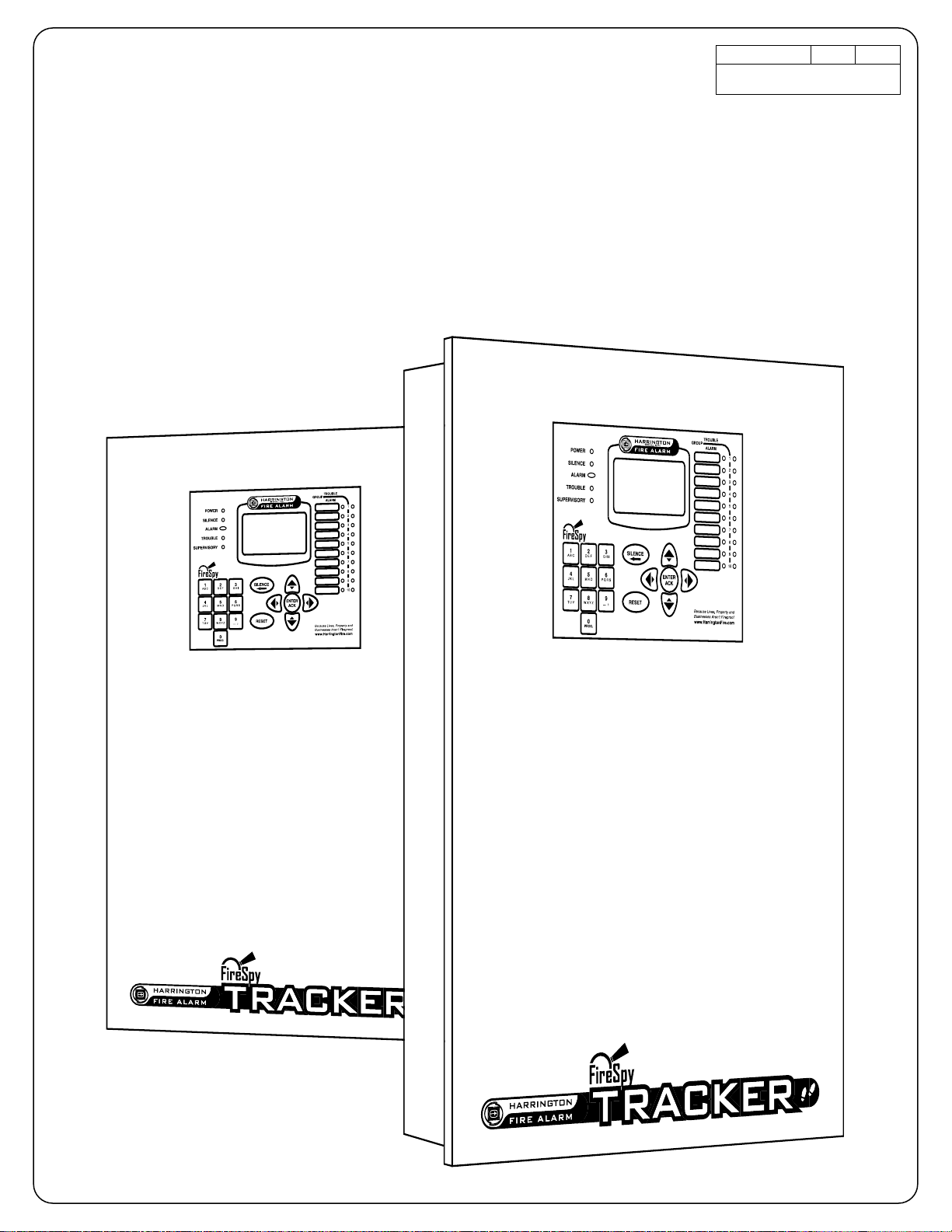
FireSpy® Tracker T1000, T2000, T8000, T2000E
Fire Alarm Systems
C
1012
Page 2

Page 3

HSI #780-0867 FireSpy Tracker Installation Manual
Contents
1 Preliminary Information .........................................................1
Contents
1.1 Safety messages – Please read before proceeding..................................................................1
1.2 Warranty ........................................................................................................................................2
1.3 Support..........................................................................................................................................2
2 Overview..................................................................................3
2.1 General ..........................................................................................................................................3
2.2 System layout ...............................................................................................................................4
2.2.1 Standalone panel ....................................................................................................................4
2.2.2 Multiple panel network.............................................................................................................4
2.3 System components.....................................................................................................................5
2.3.1 Main circuit board assembly (T1-MB, T8000-MBC, T2000-MBCLC)......................................5
2.3.2 Display board (T-PDC)............................................................................................................8
2.3.3 Network Communications adapter (T8000-NCA)....................................................................8
2.3.4 LCD annunciator (T8000-RAN / -ANN)...................................................................................9
2.3.5 Graphic annunciator................................................................................................................9
2.3.6 Addressable Signaling Line Circuit (SLC) module (T8000-LCU)............................................9
2.3.7 Conventional zone module (T8000-CM) ...............................................................................10
2.3.8 Relay module (T8000-RC) ....................................................................................................11
2.3.9 Serial relay module (T8000-SRM).........................................................................................11
2.3.10 DACT communicator module (T-UDACT).............................................................................11
2.3.11 Audio evacuation modules ....................................................................................................12
2.3.12 City tie/reverse polarity communicator (UCT) .......................................................................12
2.3.13 Enclosures.............................................................................................................................13
2.4 Service use..................................................................................................................................14
2.5 Listings and approvals ..............................................................................................................14
1
2
3
A
B
C
3 Installation and Wiring.........................................................17
3.1 System planning.........................................................................................................................17
3.1.1 Battery calculation.................................................................................................................17
3.2 Control panel installation ..........................................................................................................17
3.2.1 Preparation............................................................................................................................17
3.2.2 Panel location........................................................................................................................17
3.2.3 Installation .............................................................................................................................18
3.3 Configuration and programming ..............................................................................................19
3.4 Check system operation ............................................................................................................19
Appendix A. Ordering and Parts Information.........................29
A.1 Component matrix......................................................................................................................29
A.1.1. Available panel configurations (factory pre-wired) ................................................................29
A.1.2. Board modules ......................................................................................................................29
A.1.3. Enclosures.............................................................................................................................30
A.1.4. Accessories...........................................................................................................................30
Appendix B. Compatible Devices............................................31
B.1 Startup delay for devices with alarm verification....................................................................31
i
D
Page 4

HSI #780-0867 FireSpy Tracker Installation Manual
B.2 Addressable SLC devices (for use with T8000-LCU, T2000-MBCLC, and T1-MB)...............31
B.2.1. System Sensor......................................................................................................................31
B.2.2. Harrington Signal...................................................................................................................32
B.2.3. Apollo.....................................................................................................................................34
B.2.4. Air Products...........................................................................................................................34
B.3 Conventional two-wire smoke detectors (for use with T8000-CM)........................................35
B.3.1. Harrington Signal...................................................................................................................35
Contents
B.3.2. Apollo.....................................................................................................................................35
B.3.3. ESL/Sentrol ...........................................................................................................................37
B.3.4. System Sensor......................................................................................................................37
B.4 Releasing devices (for use with a NAC on MB / MBC / MBCLC) ...........................................37
Appendix C. Wire Selection .....................................................39
C.1 General wiring guidelines..........................................................................................................39
C.2 Wire length calculations ............................................................................................................39
C.3 Wire selection tables..................................................................................................................40
Appendix D. Battery Capacity Calculation .............................45
ii
Page 5

HSI #780-0867 FireSpy Tracker Installation Manual
1 Preliminary Information
1.1 Safety messages – Please read before proceeding
People’s lives depend on your safe installation of our products. It is important to read, understand and
follow all instructions shipped with this product. The equipment described herein is listed by the NRTL
only when installed and configured in the manner described herein
It is possible to install equipment incorrectly or arrange system components and installation wiring in such
a manner that life safety functions are not properly performed and, as a result, lives may be lost. To
minimize this possibility, become familiar with the system layout and operation of the entire FireProtective Signaling System. Do not alter any mechanical or electrical features of the equipment supplied.
Become familiar with the Building Code and Fire Prevention Code or other authority having jurisdiction
requirements in the area of the installation.
The Facilities Engineer and the Safety Engineer should make selection of mounting location for this
equipment and routing of wiring. Listed below are some other important safety instructions and
precautions you should follow:
• This unit must be installed by a qualified electrician in accordance with NFPA 72, and national and
local electrical and fire codes, under the direction of the authority having jurisdiction.
• Only authorized and competent personnel must be allowed access to panel controls or panel power
source, to limit the possibility of malfunction or failure.
• Do not connect this unit to system wiring when circuits are energized. Check field wiring lines to
ensure that voltages are not present. Warranty is void if the equipment is damaged by improperly
connected untested wiring or if fused improperly.
• The equipment must be connected to a dedicated source of reliable AC power adequate for the rating
of the system as configured. The source must be secure and properly labeled "Fire Alarm Circuit
Control".
• A suitable battery set must be used to assure required operation in case of primary power loss. The
battery set must be replaced after 4 years, or earlier if capacity is excessively reduced. The batteries
should be checked at least twice per year, or more often if required by local codes.
• Wiring used in the system must be adequate for the service and installed in accordance with
applicable codes.
• Devices used in the system and connected to the control panel must be verified compatible with the
panel.
• All effective warning speakers produce loud sounds which, in certain circumstances, may cause
permanent hearing loss. Take appropriate precautions such as wearing hearing protection.
Recommendations in OSHA Sound Level Standard (29 CFR 1910) should not be exceeded.
• After installation and completion of initial system test, provide a copy of this instruction sheet to all
personnel responsible for operation, periodic testing and maintenance of this equipment.
• After installation, ensure that all bolts and threaded joints are tightened.
• After installation and completion of initial system test, a program for periodic testing of this device
must be established. Proper periodic maintenance is required to assure operation through the life of
the system, and to determine that point at which useful life of the system or of any of its components
has been reached. Any malfunctioning units must be repaired or replaced immediately by competent,
authorized personnel. Refer to NFPA 72, local Fire Codes and the authority having jurisdiction.
• Instructions for proper response by building occupants must be developed and distributed in
accordance with the Building Code and Fire Prevention Code or other authority having jurisdiction.
• Unauthorized repair or servicing of equipment may result in degradation of performance and/or
property damage, serious injury, or death to you or others. If a malfunctioning unit is encountered, do
not attempt any field repair/retrofit of parts.
Failure to follow all safety precautions and instructions may result in property damage, serious injury, or
death to you and others.
1
2
3
A
B
C
D
1
Page 6

1
HSI #780-0867 FireSpy Tracker Installation Manual
The programming technician is ultimately responsible for conformance to the applicable codes and
purchase order.
This manual cannot cover all details or contingencies which could exist in a system application. Refer to
the authorized distributor if additional information is required.
Specifications are subject to change without notice.
Contents
1.2 Warranty
Harrington Signal products are covered by a limited warranty. See Harrington’s warranty statement for
more details (document #780-0762)
1.3 Support
If you have any questions or concerns about installation, operation, or programming of our equipment,
please contact us at:
Harrington Signal Inc.
2519 – 4th Ave
Moline, IL 61265
Toll Free: (800) 577-5758
Tel: (309) 762-0731
Fax: (309) 762-8215
Email: techservices@harringtonsignal.com
Web: www.harringtonfire.com
FireSpy is a registered trademark of Harrington Signal Inc.
This document is copyright © 2009 Harrington Signal Inc.. All rights reserved.
2
Page 7
HSI #780-0867 FireSpy Tracker Installation Manual
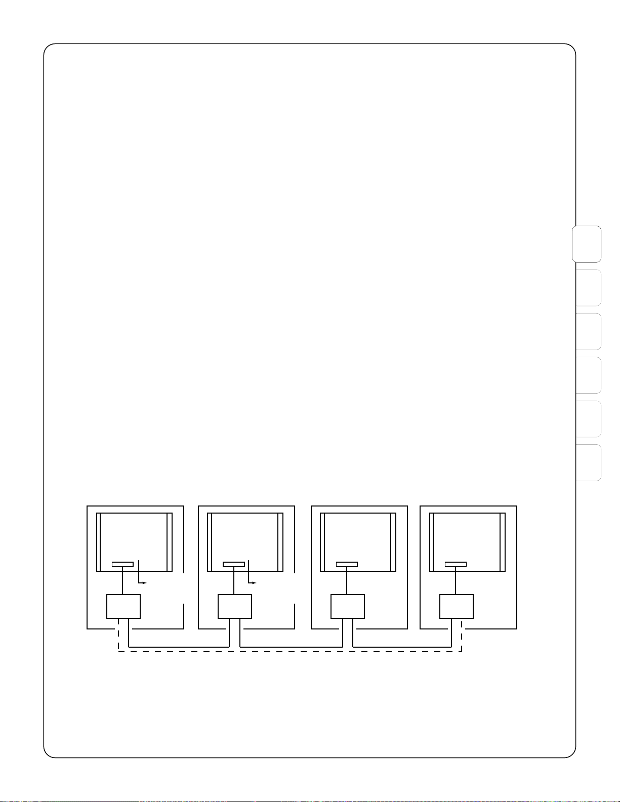
290-0103
NETWORK WIRING (RS485)
LOW CAPACITANCE TWISTED PAIR OR FIBER
DAISY-CHAIN ONLY, DO NOT T-TAP
STYLE 4 (CLASS B): SOLID LINE
STYLE 7 (CLASS A): SOLID AND DOTTED LINES
MASTER PANEL
T8000*
MASTER PANEL LOCAL PANEL LOCAL PANEL
NCA
RS485
NCA
RS485
NCA
RS485
NCA
RS485
REPORTING
EQUIPMENT
(OPTIONAL)
REPORTING
EQUIPMENT
(OPTIONAL)
MB, MBC, or
MBCLC
MB, MBC, or
MBCLC
MB, MBC, or
MBCLC
MBC
* AT LEAST ONE T8000 MASTER PANEL IS REQUIRED.
TOTAL COMBINATION OF MASTER AND
LOCAL PANELS NOT TO EXCEED 254 PANELS.
2 Overview
2.1 General
The FireSpy Tracker series panels are sophisticated microprocessor-based fire alarm control systems
suited to the various needs of commercial, industrial and institutional applications. The Tracker panel can
connect to a Tracker network, a peer-to-peer network of up to 250 Tracker panels. Up to 254 points on
each Signal Line Circuit (SLC) and up to 60 conventional fire detector zones can be configured. The
distributed system architecture reduces the length of wiring needed because addressable SLC,
conventional IDC, and other modules can be located closer to where devices are installed.
The Tracker panel functions in accordance with the National Fire Protection Association (NFPA)
Standard 72 Fire Alarm Code. Activation of a compatible detector or normally open fire alarm initiating
device will sound audible appliances, notify a remote station, annunciate a fire or alarm condition, and
energize supplementary relays.
Automatic learning features can be used to quickly configure a system. Additional system configuration
can be done through the annunciator or with a PC.
The Tracker 8000 allows up to eight SLCs for a total of 2032 addressable points. The SLCs are provided
by the use of modular SLC boards, which may be mounted in the main enclosure or remotely.
The Tracker 2000 main board (MBCLC) has two SLCs for a total of 508 addressable points.
The Tracker 1000 main board (MB) has one SLC for a total of 254 addressable points.
The Tracker T2000E combines the Tracker 2000 fire alarm control panel and the HAVE audio voice
evacuation systems into one convenient package. In addition to the features of the T2000, it also provides
conventional audio with up to 8 Class B speaker circuits (or up to 4 Class A) with amplification for 25, 50
or 100 watts. Within this manual, references to the T2000 also apply to the fire alarm portion of the
T2000E (the MBCLC main board).
2
3
A
B
C
D
Figure 2-1: Peer-to-peer network layout
3
Page 8
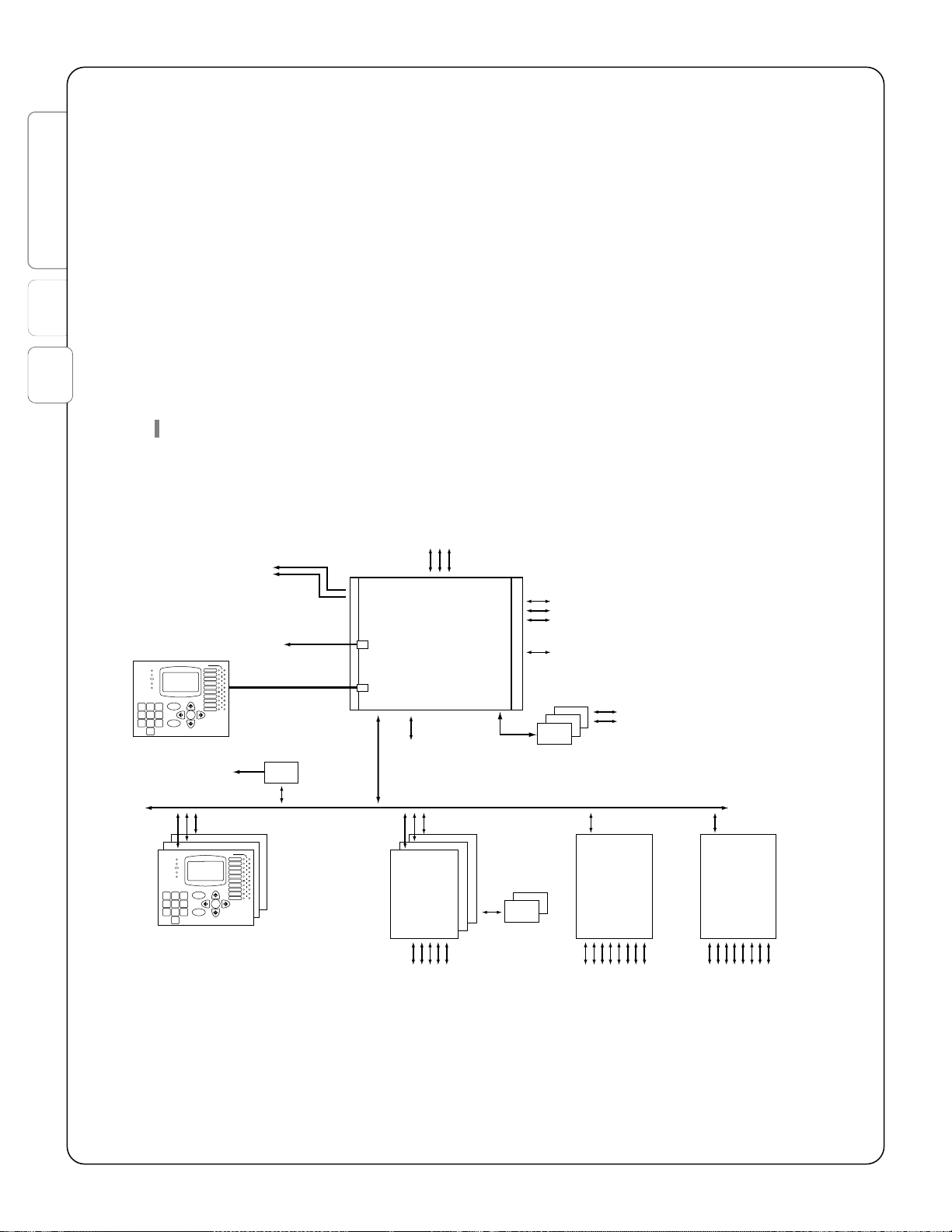
1
T1000
SYSTEM
(TO NETWORK)
TO PC
290-0158
* MAY BE INDIVIDUALLY CONFIGURED AS NAC, AUX POWER, OR INPUT
** MAY BE CONFIGURED AS NAC (FOR CONNECTION TO NAC BOOSTER OR VOICE MODULE) OR INPUT
A SYSTEM MUST USE AT LEAST ONE INITIATING DEVICE
MAIN BOARD ASS'Y
MB
RS485
(3) NACs*
(1) SLC
RELAY CONTACTS
(8) PER SRM
PHONE LINES
TO CENTRAL
OR REMOTE
STATION
RELAY
CONTACTS
(2) PER RC
RELAY CONTACTS
(2) PER RC
ANN
(7) MAX
IDC
(5) CLASS A OR
(10) CLASS B
PER CM
RC
(5) MAX
PER CM
CM
(6) MAX
SRM
(6) MAX
250 OUTPUTS
PER LDV
(250 TOTAL
CONFIGURABLE)
LDV
(4) MAX
RC
(5) MAX
USB
RELAY CONTACTS:
(1) SYSTEM ALARM
(1) SYSTEM SUPV ALARM
(1) SYSTEM TROUBLE
NCA
ANNUNCIATOR
(MOUNTED ON
MAIN CABINET
DOOR)
(1) AUX I/O**
1
2
3
4
5
6
7
8
9
10
SILENCE
POWER
ALARM
TROUBLE
SUPERVISORY
1
2
3
4
5
6
7
8
9
10
SILENCE
POWER
ALARM
TROUBLE
SUPERVISORY
2
HSI #780-0867 FireSpy Tracker Installation Manual
2.2 System layout
2.2.1 Standalone panel
A Tracker panel consists of the main board (MB for T1000, MBC for T8000 or MBCLC for T2000) in the
main enclosure and various devices that connect to the main board (see Figure 2-2). System
programming can be done from a PC or laptop through the serial port of the panel’s communications
Contents
adapter.
2.2.2 Multiple panel network
A Tracker network consists of multiple Tracker panels with each panel connected to the network through
a communications adapter (see 2.3.3 Network Communications adapter (T8000-NCA)). Local network
devices (annunciators, etc.) connect to the RS485 outputs of each panel, as they would in a standalone
panel. Each panel provides the same capabilities as it would as a standalone panel, with the addition of
the network connection. System programming can be done from a PC or laptop through the serial port of
the panel’s communications adapter.
NOTE: A Tracker network must include at least one T8000 panel, set up as master.
Figure 2-2: System layout (T1000)
4
Page 9

HSI #780-0867 FireSpy Tracker Installation Manual
T2000
,
T8000
SYSTEM
* MAY BE INDIVIDUALLY CONFIGURED AS NAC, AUX POWER, OR INPUT
A SYSTEM MUST USE AT LEAST ONE INITIATING DEVICE
(TO NETWORK)
TO ONE OF:
- PRINTER (straight cable)
- MODEM (straight cable)
TO PC
290-0104
(2) SLCs
T2000 ONLY
MAIN BOARD ASS'Y
MBC (T8000) OR
MBCLC (T2000)
RS485
(4) NACs*
RELAY CONTACTS
(8) PER SRM
PHONE LINES
TO CENTRAL
OR REMOTE
STATION
RELAY
CONTACTS
(2) PER RC
RELAY CONTACTS
(2) PER RC
SLC
(2) PER LCU
ANN
(15) MAX (T8000)
(7) MAX (T2000)
IDC
(5) CLASS A OR
(10) CLASS B
PER CM
RC
(5) MAX
PER CM
CM
(6) MAX
SRM
(6) MAX
UDACT
250 OUTPUTS
PER LDV
(250 TOTAL
CONFIGURABLE)
LDV
(4) MAX
RC
(5) MAX
LCU
(4) MAX
RS232
USB
RELAY CONTACTS:
(1) SYSTEM ALARM
(1) SYSTEM SUPV ALARM
(1) SYSTEM TROUBLE
NCA
T8000 ONLY
1
2
3
4
5
6
7
8
9
10
SILENCE
POWER
ALARM
TROUBLE
SUPERVISORY
1
2
3
4
5
6
7
8
9
10
SILENCE
POWER
ALARM
TROUBLE
SUPERVISORY
2.3 System components
The Tracker is a modular system. Each module may be purchased and installed separately. Some
common system configurations are also available pre-assembled at the factory.
2.3.1 Main circuit board assembly (T1-MB, T8000-MBC, T2000-MBCLC)
The main circuit board assembly (T1-MB, T8000-MBC or T2000-MBCLC) is the core of the Tracker panel.
It contains the main board and power supply mounted on a metal chassis. The MB / MBC / MBCLC
mounts in the main panel enclosure.
The T1-MB, T8000-MBC and T2000-MBCLC are respectively referred to as MB, MBC and MBCLC in this
manual.
2
3
A
Figure 2-3: System layout (T2000, T8000)
5
B
C
D
Page 10

1
2
HSI #780-0867 FireSpy Tracker Installation Manual
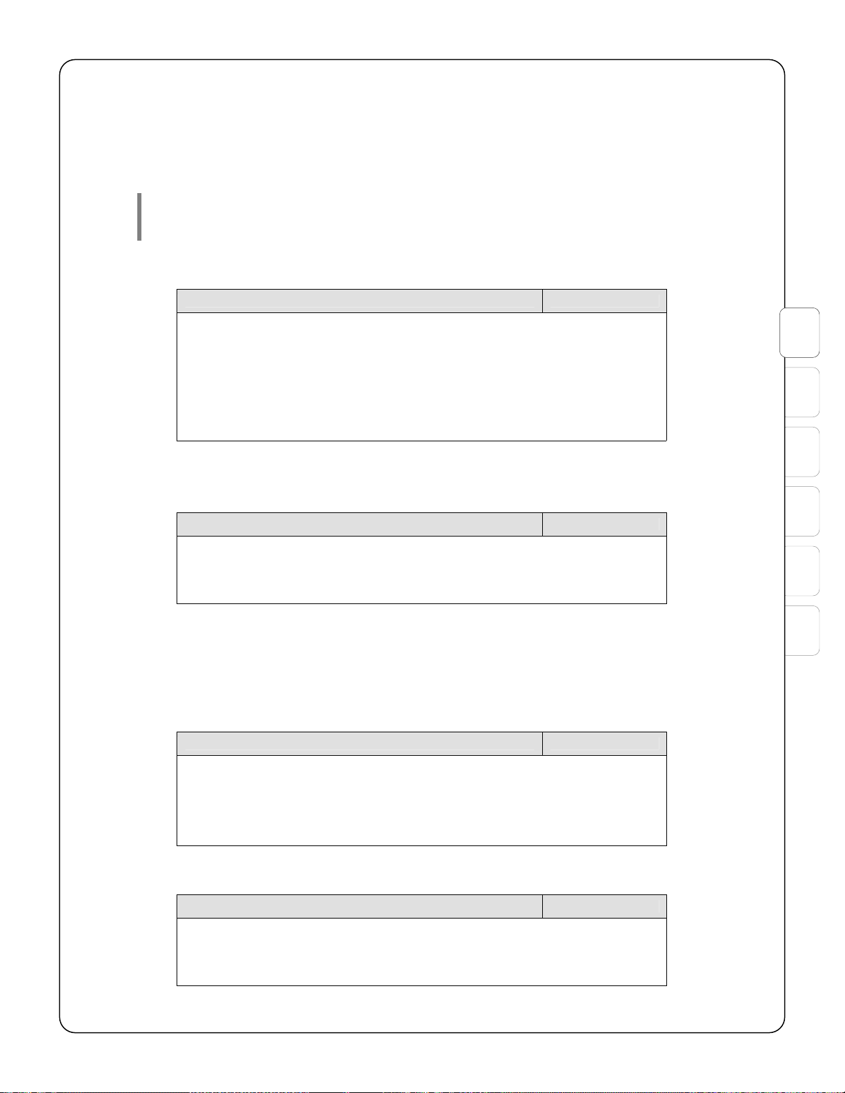
Table 2-1: Power supply specifications (MBC/MBCLC).
Parameter Rating
Input voltage (AC supply) 120VAC @ 50/60Hz
Input current draw (AC supply) 1.8A @ 120VAC
Contents
24VDC power available (total system current) and max battery load 7A
Battery charge voltage, max 27.6V
Battery charge current, max 1.6A
Battery capacity
Min
Max
Use two UL864 listed 12V batteries connected in series.
Table 2-2: Power supply specifications (MB).
Parameter Rating
Input voltage (AC supply) 120VAC @ 50/60Hz
Input current draw (AC supply) 1.8A @ 120VAC
24VDC power available (total system current) and max battery load 4A
Battery charge voltage, max 27.6V
Battery charge current, max 1.6A
Battery capacity
Min
Max
Use two UL864 listed 12V batteries connected in series.
230VAC @ 50/60Hz
0.4A @ 230VAC
8Ah
40Ah
240VAC @ 50/60Hz
2.15A @ 240VAC
7Ah
40Ah
Table 2-3: Environmental specifications (MB / MBC / MBCLC).
Parameter Rating
Environment
UL864 location
Temperature range
Maximum relative humidity
Indoor, dry
32 to 120° F
93%
Table 2-4: RS-485 specifications (MB / MBC / MBCLC).
Parameter Rating
Output voltage (MBC / MBCLC) 24VDC
Max output current (MBC / MBCLC) 2.5A
Max impedance, RS-485 wiring* 100 ohms
Max capacitance, RS-485 wiring* .3uF
Max impedance, power wiring, total (3V drop each wire @ 80mA)*
(MBC / MBCLC)
* See Appendix C Wire Selection for suggested wiring distances.
75 ohms
6
Page 11
HSI #780-0867 FireSpy Tracker Installation Manual
The main circuit board contains 4 circuits (3 for MB) that can be individually programmed to operate in the
following modes:
• NAC (steady, temporal coding, or march time coding, Gentex 1 synchronization for Commander 3
and 4, Gentex 2 synchronization for Commander 1)
• Auxiliary power supply (resettable or continuous)
• Auxiliary input
NOTE: UL864 requires audible alarm notification devices to be synchronized on a
circuit or a system basis. If using notification appliances other than Gentex
Commander 1, 3, or 4, synchronization modules must be used.
Table 2-5: NAC specifications (output modes) (MB / MBC / MBCLC)
Parameter Rating
Output voltage 24VDC
Output current, max
MBC / MBCLC
MB
Wiring styles (NAC mode) Style Y (Class B)
End-of-line resistance (NAC mode, Class B) 10k ohm
* See Appendix C Wire Selection for suggested wiring distances.
3A
1.8A
Style Z (Class A)
2
3
A
Table 2-6: NAC specifications (input mode) (MB / MBC / MBCLC)
Parameter Rating
Input voltage (input mode) 24VDC
Input current draw, max (input mode), inherently power limited 5mA
End of line resistance (input mode) 10k
The MB contains an auxiliary input/output circuit that can be used in a NAC mode or as an input. The
NAC mode can be used to activate an external NAC-driven device, such as a NAC power supply or
HAVE voice evacuation system. The AUX IO port provides alarm activation, silencing and resound
operation.
Table 2-7: AUX IO specifications (output mode) (MB)
Parameter Rating
Output voltage 24VDC
Output current, max 0.02A
Wiring styles Style Y (Class B)
End-of-line resistance 10k ohm
Table 2-8: AUX IO NAC specifications (input mode) (MB)
B
C
D
Parameter Rating
Input voltage (input mode) 24VDC
Input current draw, max (input mode), inherently power limited 5mA
End of line resistance (input mode) 10k
7
Page 12

1
HSI #780-0867 FireSpy Tracker Installation Manual
The main board contains (1) common alarm relay output, (1) common supervisory alarm relay output, and
(1) common trouble relay output, as well as a connection for up to (5) relay modules (T8000-RC).
Table 2-9: Output relay specifications (MB / MBC / MBCLC)
Parameter Rating
Type Form C (SPDT)
Contents
Contact rating
MBC / MBCLC resistive load, PF=1.0
inductive load, PF=0.4
MB resistive load, PF=1.0
* Limited to 50VDC due to spacing
10A @ 30VDC
10A @ 240VAC*
3A @ 240VAC*
2A @ 30VDC
2
Table 2-10: SLC specifications (MB / MBCLC)
Parameter Rating
Loop output voltage 32V @ 10kHz
Max loop output current 400mA max
Max loop capacitance 0.5uF
Max loop impedance (total per loop) 40 ohms
Environment
UL864 location
Temperature range
Maximum relative humidity
* See Appendix C Wire Selection for suggested wiring distances.
Indoor, dry
32 to 120° F
93%
2.3.2 Display board (T-PDC)
The display board may mount either inside the enclosure door so its buttons are accessible with the door
closed or on the chassis assembly (MBC or MBCLC only) so it is accessible after unlocking and opening
the enclosure. When the PDC is mounted on the door and connected to the keyswitch, the keyswitch
must be activated to enable keypad access to the system’s security-sensitive control functions.
2.3.3 Network Communications adapter (T8000-NCA)
The network communications adapter is used with each panel in a networked system. It allows the
connected panel to communicate with other panels on the panel network.
Table 2-11: Communications adapter (T8000-NCA) specifications.
Parameter Rating
Input voltage Regulated 24 DC
Input current draw 60 mA
Max impedance, RS485 communication wiring, total 40 ohms*
Max capacitance, RS485 communication wiring 0.3 uF*
Environment
UL864 location
Temperature range
Maximum relative humidity
* See Appendix C Wire Selection for suggested wiring distances.
Indoor, dry
32 to 120° F
93%
8
Page 13
HSI #780-0867 FireSpy Tracker Installation Manual
2.3.4 LCD annunciator (T8000-RAN / -ANN)
The Tracker 8000 allows up to 15 remote display annunciators (Model T8000-ANN or T8000-RAN). The
T2000 and T1000 allow up to 7 remote annunciators. The T8000-ANN remote annunciator is intended for
surface or flush mounting and is comprised of the T8000-RAN module within the T8000-A-CAB cabinet.
Table 2-12: Remote annunciator (T8000-RAN/T8000-ANN) specifications.
Parameter Rating
Dimensions (backbox of T8000-ANN) 8.5H x 10W x 2D
Input voltage 24VDC
Input current draw
Standby
Alarm, without backlight
Alarm, with backlight (10 seconds after key press)
Max impedance, power wiring, total (3V drop each wire @ 80mA)* 75 ohms
Environment
UL864 location
Temperature range
Maximum relative humidity
* See Appendix C Wire Selection for suggested wiring distances.
(inches)
19mA
25mA
80mA
Indoor, dry
32 to 120° F
93%
2
3
A
2.3.5 Graphic annunciator
A graphic annunciator module (T8000-LDV) is for use in appropriately UL864 Listed custom enclosures to
provide graphic annunciator capabilities. The module may be configured to use either LED or
incandescent lamps; either type of output is supervised. Up to 4 lamp annunciator modules may be used
for a total of 250 programmable outputs per Tracker panel. Additionally, each module has outputs for
power on, common alarm and common trouble visual indicators and a sounder.
Table 2-13: Lamp annunciator module (T8000-LDV) specifications.
Parameter Rating
Input voltage 24VDC
Input current draw
Standby (no devices)
Alarm (full load)
Max impedance, RS-485 wiring* 100 ohms
Max impedance, power wiring, total (3V drop each wire @ ?? mA)* ?? ohms
Environment
UL864 location
Temperature range
Maximum relative humidity
* See Appendix C Wire Selection for suggested wiring distances.
TBD
Indoor, dry
32 to 120° F
93%
B
C
D
2.3.6 Addressable Signaling Line Circuit (SLC) module (T8000-LCU)
The Tracker panel monitors addressable fire detection devices that are connected to up to (4) loop
modules (T8000-LCU).
Each loop module provides the following:
• Two Signaling Line Circuits (SLCs).
• Up to 254 addressable analog devices can be installed on any loop (limited by device protocol).
9
Page 14

HSI #780-0867 FireSpy Tracker Installation Manual
• Compatible with System Sensor, Apollo, Harrington and Air Productsdevices (see Appendix B for
details).
• Mounts in the main enclosure or remotely (see Table 2-20)
Table 2-14: Addressable SLC module (T8000-LCU) specifications.
1
2
Contents
Parameter Rating
Input voltage 24V
Input current draw
Standby (no devices)
Alarm (full load)
Max impedance on 24VDC input wiring (per side) 2 ohms
Loop output voltage 25V
Max loop output current 400mA max
Max loop capacitance 0.5uF
Max loop impedance (total per loop) 100 ohms
Environment
UL864 location
Temperature range
Maximum relative humidity
* See Appendix C Wire Selection for suggested wiring distances.
2.3.7 Conventional zone module (T8000-CM)
The Tracker panel monitors conventional fire detection devices that are connected to conventional zone
modules (T8000-CM). Each zone module provides 5 Class A zones or 10 Class B zones for FireSpy
conventional devices. Zone modules may be mounted in the main enclosure or in remote enclosures.
107mA
Indoor, dry
32 to 120° F
93%
Table 2-15: Conventional IDC module (T8000-CM) specifications.
Parameter Rating
Input voltage 24V
Input current draw
Standby (no detectors)
Alarm, base module current
Alarm, each additional zone in alarm*
Max impedance, power wiring, total (3V drop each wire) 6V divided by total
Max impedance, RS-485 wiring* 100 ohms
Zone output voltage (normal standby) 26.5V
Zone output current
Supervision
Short circuit
Zone impedance (total per loop), max 100 ohms
Zone end-of-line resistor 4.7k ohms
Environment
UL864 location
Temperature range
Maximum relative humidity
* For total alarm current, add 14mA plus 40mA for each additional zone used
** See Appendix C Wire Selection for suggested wiring distances.
11mA
14mA
40mA
alarm current*
5mA
40mA
Indoor, dry
32 to 120° F
93%
10
Page 15

HSI #780-0867 FireSpy Tracker Installation Manual
2.3.8 Relay module (T8000-RC)
The T8000-RC relay module has (2) form C (SPDT) relays, providing individually programmable dry
contact outputs. Up to (5) relay modules may be daisy-chained, with the first one connected to a
conventional zone module (T8000-CM) or the main board (MB, MBC, MBCLC) via the relay output
connector. Relay modules may be mounted in the main enclosure or remotely (see Table 2-20).
Table 2-16: Relay module (T8000-RC) specifications.
Parameter Rating
Input current draw
Standby
Alarm
Relay type Form C (SPDT)
Contact rating
resistive load, PF=1.0
inductive load, PF=0.4
UL864 location Indoor, dry
Temperature range 32 to 120° F
Maximum relative humidity 93%
2mA
25mA
10A @ 30VDC
10A @ 240VAC
3A @ 240VAC
2.3.9 Serial relay module (T8000-SRM)
The T8000-SRM module provides (8) programmable relays. It may be mounted in the main enclosure or
remotely (see Table 2-20).
2
3
A
B
Table 2-17: Relay module (T8000-SRM) specifications.
Parameter Rating
Input current draw
Standby
Alarm
Max impedance, power wiring, total (3V drop each wire)* 26 ohms
Max impedance, RS-485 wiring* 100 ohms
Relay type Form C (SPDT)
Contact rating
resistive load, PF=1.0
inductive load, PF=0.4
Environment
UL864 location
Temperature range
Maximum relative humidity
30mA*
230mA*
10A @ 30VDC
10A @ 240VAC
3A @ 240VAC
Indoor, dry
32 to 120° F
93%
2.3.10 DACT communicator module (T-UDACT)
The T-UDACT is used for off-premises monitoring of the Tracker system. The T1000 has the DACT builtin. For the T2000 or T8000, the DACT mounts in the main cabinet or in a separate UL864 listed
enclosure. Programming is done through the Tracker user interface or a PC with the Tracker PC
Programmer software.
Signals are sent to a Digital Alarm Communicator Receiver (DACR) using either a primary or secondary
telephone line. A test call is transmitted to the DACR every 24 hours.
C
D
11
Page 16

1
2
HSI #780-0867 FireSpy Tracker Installation Manual
The DACT flashes the Fault LED when it recognizes a fault condition on itself. The following are the
possible fault conditions.
• Loss of communication with the fire panel. The DACT will attempt to communicate a trouble condition
to the central station
• Low or missing phone line voltage
Contents
Table 2-18: T-UDACT module specifications (T2000 / T8000).
Parameter Rating
Input current draw
Standby
Alarm
Environment
UL864 location
Temperature range
Maximum relative humidity
* Refer to T-UDACT installation instructions for other specifications.
30mA
32mA
Indoor, dry
32 to 120° F
93%
2.3.11 Audio evacuation modules
These are the core of the audio system. The T2000E provides space for one of the following amplifier
modules: 25HAVE, 50HAVE, or 100HAVE. Amplifier modules contain an amplifier, tone generator, digital
message repeater, and supervisory interface. The amplifier provides a total of 25, 50, or 100 watts to the
speaker outputs at 25 or 70 VRMS. The number in the model number indicates the number of watts
available. The speaker outputs can be configured as a Class A (Style Z) or Class B (Style Y) speaker
zone. The T2000E enclosure has space to connect up to two zone splitter modules:
* ZSC-2A: Splits a zone into two Class A (Style Z) speaker zones
* ZSC-4B: Splits a zone into four Class B (Style Y) speaker zones
2.3.12 City tie/reverse polarity communicator (UCT)
The model UCT interfaces between the Tracker and a local energy city box or remote station (reversepolarity). The UCT provides a form C system trouble contact and a form C general alarm contact. The
interface from the control panel is via 24VDC inputs for alarm, supervisory alarm, and trouble. A
disconnect switch is provided to prevent false alarms while the system is being tested or serviced.
When configured for remote station, this module is intended for connection to a polarity reversal circuit of
a remote station receiving unit having compatible ratings. This module is not suitable for Remote Station
Protected Premises service where separate transmission circuits are required for fire, supervisory, and
trouble signals. When configured for local energy, this module is intended for connection to a local energy
city tie box having compatible ratings.
12
Page 17

HSI #780-0867 FireSpy Tracker Installation Manual
Table 2-19: City tie/reverse polarity communicator (UCT) specifications.
Parameter Rating
Supply voltage 24V*
Input current draw 350mA max
Relay contacts
Trouble contacts
Alarm contacts
Remote station transmitter circuit outputs (power limited)**
Voltage
Current
Local energy city tie outputs (not power limited)
Standby voltage
Standby current
Alarm voltage
Alarm current
Ripple voltage (alarm)
Intended trip coil
* The same power source must be used for powering the UCT and relay contact wiring.
** These circuits are to be supervised by the remote station.
1A @ 28VDC, form C
5A @ 28VDC, form C
16.5 – 24.6VDC
14mA max
18-40mVDC
1.5mA max
16-28VDC
270mA max (momentary load)
1.2V max
14.5 ohm
2.3.13 Enclosures
2
3
A
Table 2-20: Enclosure dimensions and module mounting provisions.
T1-CAB
Size (inches)
Overall
Backbox
Knockouts
(1-1/8 dia)
Module Quantity of modules that may be mounted
T1-MB 1
T8000-MBC or
T2000-MBCLC or
T8000-LCU 2* 2*
T8000-CM 2* 2*
T8000-SRM 1* 1*
T8000-RC 2
T-UDACT 1
T8000-NCA 1
25HAVE, 50HAVE,
or 100HAVE
ZSC-2A or ZSC-4B 2*
Batteries (2) 12V, up to 12Ah** (2) 12V, up to 12Ah** (4) 12V, up to 18Ah†
* A total of two mounting locations are provided for a combination of these modules.
** Larger batteries may be mounted in an auxiliary UL864 Listed enclosure.
† Two batteries are for the fire system and two batteries are for the audio system. 100HAVE may use up to 24Ah batteries.
W x H x D
15.88 x 25.19 x 4.8
14.5 x 23.5 x 4
4 top
3 each side
1 1
1
T8000-CAB
T2000-CAB
W x H x D
15.88 x 25.19 x 4.8
14.5 x 23.5 x 4
4 top
3 each side
T2000E-CAB T8000-EXP
W x H x D
19.25 x 33.25 x 4.5
18 x 32 x 4
3 top, 2 bottom,
4 each side
W x H x D
11.37 x 15.44 x 3.8
10 x 14 x 3
3 top
3 bottom
B
C
D
13
Page 18

1
2
HSI #780-0867 FireSpy Tracker Installation Manual
T8000-A-CAB T8000-EXP5 T8000-EXP5N
Size (inches)
Overall
Backbox
Knockouts
(1-1/8 dia)
Contents
Module Quantity of modules that may be mounted
T8000-CM 1
T8000-RC 5 5
T8000-RAN 1
W x H x D
11.37 x 9.94 x 2.8
10 x 8.5 x 2
3 top
3 bottom
W x H x D
15.88 x 19.44 x 3.8
14.5 x 18 x 3
4 top
4 bottom
W x H x D
7.38 x 19.5 x 2.88
6 x 18.13 x 3.13
2 top
2 bottom
4 each side
2.4 Service use
The Tracker is suitable for the following NFPA72 service uses:
Table 2-21: Service uses.
Type Service Signaling Required Equipment
Local (PPU) A, M, SS, WF, R Non-coded, march time
Proprietary (PPU) A, M, SS, WF, R Multiplex
Remote Station (PPU) A, M, SS, WF, R DACT
Reverse polarity
Central Station (PPU) A, M, SS, WF, R DACT T-UDACT*
Auxiliary (PPU) A, M, WF, R N/A UCT
Abbreviations for services:
A = Automatic fire alarm
M = Manual fire alarm
SS = Sprinkler supervisory service
WF = Waterflow alarm
R = Releasing device service
* The T-UDACT is required equipment for these uses on the MBC and MBCLC. It is not required for these uses on the MB
because the MB has a built-in DACT.
T-UDACT*
UCT
2.5 Listings and approvals
ETL Listed: Standard UL864
CSFM Listed 7165-0476:172 (T2000, T8000)
MEA/BSA MEA 43-05-E, 43-05-E Vol 2 (T2000, T8000)
14
Page 19

HSI #780-0867 FireSpy Tracker Installation Manual
3 Installation and Wiring
Installation of the panel and system accessories requires qualified, trained, and equipped personnel who
are familiar with both the fire alarm codes and installation methods for this specific equipment. Final
programming requires special familiarity with the applicable local codes. The versatility of this system
implies sensitivity to mishandling and misprogramming beyond that of less capable equipment.
3.1 System planning
3.1.1 Battery calculation
The battery provides a secondary source of power if loss of primary power occurs. The batteries need to
have enough capacity to provide power for the control panel and attached devices for a minimum standby
period followed by an alarm period. Follow the directions below to fill in the calculation template in the
appendix.
The first section calculates the current draw loads for standby and alarm conditions.
1. Fill in the quantity and calculate standby and alarm current draw totals for each system
component.
2. Fill in the quantity and calculate standby current draw totals for each detector, base, and module.
3. Use rows A, B, C and D to estimate the total alarm current for detector and module LEDs. Row B
assumes that 5% of the LEDs of these devices will be turned on.
4. Fill in the quantity and calculate total alarm current for each NAC circuit.
5. Calculate the sum columns E and F. Verify that these values are within the limits of the power
supply (see table at the bottom).
6. Verify that the current draw on each circuit is within the current limit of the circuit.
The second section calculates the battery size needed to sustain the loads for the minimum time
durations.
1. Enter the standby and alarm time according to the type of system (see table at the bottom).
2. Fill in and calculate the remaining rows above row h and calculate row i.
3. Row i shows the battery size that is needed. Select a battery that is the next available size bigger
than this value.
3
A
B
C
D
3.2 Control panel installation
3.2.1 Preparation
Verify that all installation materials are on-hand. Read all instructions before beginning installation.
To avoid degradation of the operating circuitry, it is recommended that the printed circuit boards be
removed during cabinet mounting, wire installation, and any other procedures that may introduce dust,
metal shavings, grease or any other foreign matter into the area of the electronic circuitry.
WARNING: In an extended system, there may be several sources of power on devices
connected into the control unit. All power must be disconnected during
installation or wiring of system components and not introduced until
installation is complete and checked out.
3.2.2 Panel location
The control unit should be located on the ground floor and easily accessible to authorized personnel. The
area should be reasonably free of dust, vibration, and moisture and a dedicated source of power must be
available. The mounted enclosure should be at a convenient height to facilitate servicing.
15
Page 20

1
2
3
HSI #780-0867 FireSpy Tracker Installation Manual
Annunciators should be mounted at convenient locations, at approximately eye-level.
3.2.3 Installation
Mount the enclosure
Remove circuit boards from the enclosure before mounting to avoid damage. Refer to enclosure
Contents
documentation for detailed installation instructions.
If an auxiliary power supply or battery enclosure is being used at the panel, it may be mounted directly
below the main panel enclosure, close-nippled, with a minimum of 1 inch between enclosures for door
clearance. Wiring to these devices should be as short as possible to minimize voltage drop
Prepare for wiring
Break out the required entry points and attach any required conduit. Run the system wires and label each
adequately for future reference. The enclosure door may be temporarily removed for easier access by
removing the screw at the bottom hinge and detaching the ground wire at one end.
Note that the code requirements for power-limited wiring apply to most external runs, and the
requirements for non-power-limited wiring apply to the mains power inputs.
Install main circuit board and chassis set
For T1000, mount the main circuit board assembly (MB) onto the enclosure studs with the board oriented
as shown in Figure 3-4. Secure with #8 nuts.
For T2000 or T8000, mount the main circuit board assembly (MBC or MBCLC) onto the enclosure studs
with the board oriented as shown in Figure 3-6. Secure with #10 nuts.
For T2000E, mount the main circuit board assembly (MBCLC) onto the enclosure studs with the board
oriented as shown in Figure 3-8. (T2000E). Secure with #10 nuts.
Install optional accessories
To install accessory assemblies, follow the installation instructions provided with the accessories (see
Appendix A).
Connect AC power circuits
Wire the dedicated AC supply line to the terminals on the main circuit board as shown. The supply should
have a separate fuse or breaker at the main distribution panel so that no other electrical devices can
initiate power loss in the circuit. The grounding conductor must be at least 14AWG and 15A protection is
required. Be sure that the ground terminal is wired directly to the electrical panel ground bonding point or
another acceptable earth ground. The neutral wire must connect to the electrical panel neutral distribution
bar and not directly to ground.
WARNING Dangerous voltages appear on these terminals and associated circuitry when
the AC supply is turned on. Be sure the circuit is protected from inadvertent
energization during the assembly process.
Connect external circuits
When all remote devices have been connected to their circuits, connect these circuits to the panel (see
Figure 3-1, Figure 3-2 and Figure 3-3).
CAUTION: To maintain proper operation and supervision of detectors, indicators, and
modules, it is necessary that wiring instructions with the devices be followed
exactly, particularly with regard to in and out connections to the devices. It is
also necessary that each addressable device be properly programmed with
address and status (if applicable), and in conformance with the building
system layout. Misaddressed or miswired devices may cause severe
malfunctions and be difficult to locate.
16
Page 21

HSI #780-0867 FireSpy Tracker Installation Manual
Mount the door
If the door was removed, remount it by installing the screw at the bottom hinge and reattaching the
ground wire.
For T1000, connect the cable from the annunciator on the door to the main board.
Frame and mount a copy of the operating instructions found in the appendix to the wall near the panel.
Install batteries
WARNING: Improperly connecting or shorting the battery terminals may cause severe
damage to the panel and/or batteries and might result in personal injury.
Place the required batteries in the space provided at the bottom of the control panel enclosure. If a
battery set larger than 12Ah is required, an additional battery enclosure is required.
The 24V battery set required by the panel consists of two 12V sealed lead-acid batteries connected in
series.
Attach the red wire to the red or + terminal of one battery. Attach the black wire to the black or – terminal
of the other battery. Connect a jumper wire between the remaining two battery terminals.
Apply system power
Energize the AC power lines to the panel. The AC Power LED at the annunciator should be illuminated.
3
A
3.3 Configuration and programming
Initial configuration by scanning the network and loops will give all devices their initial default parameters
and assign input and control devices to the default group. Performing the scan is recommended to assure
that all accessories are as selected and at the assigned addresses. However, most systems also require
specific programming. Refer to the programming manual for more instructions.
3.4 Check system operation
Initial acceptance testing is required before normal operation of the system. Inspection, testing, and
maintenance may be performed by the owner, if qualified, or by a qualified contractor. Service personnel
must be qualified and experienced in inspection, testing, and maintenance of fire alarm systems,
including certification by the manufacturer or a recognized authority.
Any individuals or facilities receiving transmitted alarm, supervisory, or trouble signals, and all building
occupants, must be notified before commencement and on completion of any test operations, to prevent
unnecessary response.
Initial acceptance testing includes complete visual inspection and verifying the items below. NFPA 72 or
the authority having jurisdiction may include additional requirements that must be followed.
• Correct function of the control panel in receipt of all functional inputs and operation of all signals and
auxiliary functions, and supervision of shorts, opens, grounds, power supply faults and battery faults.
• Instrument measurement of the integrity and isolation of all applicable conductors (unpowered).
o No improper shorts or opens.
o No stray voltages between installation conductors and other conductors or ground. The maximum
stray voltage must not exceed 1 volt ac/dc.
o All conductors not intentionally grounded must be isolated from ground by at least 500k ohms
(2.2M ohms for T1000). An isolation of 10k or less will cause a ground fault. An isolation of
between 10k and 500k (10k and 2.2M for T1000) might or might not cause a ground fault, or will
cause intermittent ground faults.
B
C
D
17
Page 22

1
2
3
HSI #780-0867 FireSpy Tracker Installation Manual
o All conductors not intentionally connected together must be isolated from each other and from
ground.
• Loop resistance of each initiating and indicating circuit conductor loop must be recorded and must not
exceed the resistance of the equivalent of maximum wire length and end-of-line device.
• Operation of lamps, LEDs, and displays
• Rated power supply load, and charging capability and parameters.
Contents
o Power supply must be tested under worst-case maximum load with the battery disconnected.
o With the batteries charged and on trickle charge from the power supply, the terminal voltage shall
be approximately 27.6v.
• Visual inspection of the batteries and system connections must verify sound condition before
conducting back-up power tests.
• Operation of back-up supply (battery), including standby and alarm load capability.
o With the AC supply to the panel disconnected, the power loss trouble must be indicated, and the
standby and alarm current demand measured. General alarm systems must be operated for at
least 5 minutes to demonstrate the capability of operating standby and alarm on battery power.
• Proper operation of all audible and visual trouble signals, including ground-fault indication when any
conductor is grounded.
• Proper operation of annunciators shall be verified, including fault conditions.
• Function of all detection devices.
o Smoke and thermal fire detectors must be tested per manufacturer's instructions.
o Manual fire alarm boxes and other input devices must initiate alarm.
• Function of all other sensing or initiating devices must be tested under defined operating conditions
according to manufacturer's specifications.
• Function of all supervisory devices must be tested under operating conditions as specified by the
manufacturer.
• Function of all notification devices, including visible indicators verified against approved plans and
audible output levels measured with a sound level meter.
• Alarm verification time delay and alarm response must be verified for circuits so programmed.
• Circuit supervision must be verified by creating open circuits.
• Normal and trouble operation of the DACT, if used, and connection to two separate telephone lines
must be verified.
Any change in system hardware or software must be followed by complete test of the items involved and
10% of the unchanged items up to 50 devices. Full change records must be kept, as well as the system
test records. Changes to the control panel require retest of all critical functions.
18
Page 23

HSI #780-0867 FireSpy Tracker Installation Manual
290-0159
NOTES:
1) Use only smoke detectors that are in the compatibility list in the
owner's manual.
2) Leave end-of-line resistors on unused circuits.
3) Combined load of all devices, including indicating appliances, is not to
exceed 4A.
TYPICAL
STYLE Y
(CLASS B)
WIRING
USB
PORT
10K
LINE
NEU/LINE
EARTH
14 AWG MIN.
RJ31X
RJ31X
LINE INPUT
120VAC - 50/60Hz
240VAC - 50/60Hz
TO EXTERNAL
SERIAL MODULES
TYPICAL STYLE Z
(CLASS A)
WIRING
(end-of-line resistor
not needed)
CONTACTS RATED
2A @ 30VDC
1.0 POWER FACTOR
USE ONLY POLARIZED
DEVICES ON NACs
Polarity shown is alarm condition
ALL NACs ARE REGULATED 24 DC
+- - +
RS485 RS485
B+A+ A-B- B+A+ A-B-
NAC2 NAC3 /
AUX PWR
B+
A+ A-B-
NC
COM
NO
NC
COM
NO
NC
COM
NO
-
+
+
-
RC
RELAYS
NAC1
RELAY1RELAY2AUX I/O
BATT
TROUBLE
TO INTERNAL
SERIAL MODULES
A+A- B- B+
SLC
+
+
+
+
10K
USB
SECNDRY
PHONE
PRIMARY
PHONE
PDC
MB
J4
SW1
LEDs
FH1 FUSE: 7.5A MAX
CAUTION: For continued protection against risk of fire,
replace only with same type and rating of fuse.
FH1
24VDC, .02A
10K
Marks non-supervised circuits
Marks non-power-limited circuits
All others are supervised and power limited.
Segregate power-limited wiring from
non-power-limited wiring by at least 1/4 inch.
SUPERVISED AND POWER LIMITED
S
P
S
P
P
P
P
P
P
TO RC
TO ANNUNCIATOR
ON CABINET DOOR
J4 jumpers present
TYPICAL STYLE 4 (CLASS B) WIRING
SLC B-
SLC B+
Example SLC wiring Example RJ31X wiring
Isolators (optional) separate each zone
TYPICAL STYLE 6 (CLASS A) WIRING
ZONE 1
SLC A-
SLC A+
SLC B-
SLC B+
SLC A-
SLC A+
SLC B-
SLC B+
ZONE 2
Isolators separate each detector
Remove J4 jumpers
Remove J4 jumpers
TYPICAL STYLE 7 (CLASS A) WIRING
TIP
HOUSE
RING
TIP
TELCO
RING
GRAY
BROWN
GREEN
RED
3
A
B
C
D
Figure 3-1: Wiring on MB
19
Page 24

HSI #780-0867 FireSpy Tracker Installation Manual
290-0127
NOTES:
1) Use only smoke detectors that are listed in compatibility listing in
owner's manual.
2) Leave end-of-line resistors on unused circuits.
3) All terminals are rated for 14-22 AWG wire unless otherwise noted.
4) Combined load of all devices, including indicating appliances, is not to
exceed 7A.
TYPICAL
STYLE B (CLASS B)
WIRING
4.7k
4.7k
A+
A- B+B-
ZONE
TYPICAL
STYLE D (CLASS A)
WIRING
TYPICAL
STYLE Y
(CLASS B)
WIRING
USB
PORT
ETHERNET
PORT
(OPTIONAL)
SERIAL
PORT
10K
LINE
NEU/LINE
EARTH
LINE INPUT
120VAC - 50/60Hz
230VAC - 50/60Hz
RS485
TO SERIAL
MODULES
TYPICAL STYLE Z
(CLASS A)
WIRING
(end-of-line resistor
not needed)
CONTACTS RATED
10A @ 30VDC
10A @ 250VAC
1.0 POWER FACTOR
USE ONLY POLARIZED
DEVICES ON NACs
Polarity shown is alarm condition
ALL NACs ARE REGULATED 24 DC
+- - +
24VDCP1RS485
B+A+ A-B- B+A+ A-B-
P7 NAC
B+
A+ A-B-
P8 NAC
B+
A+ A-B-
NC
COM
NO
NC
COM
NO
NC
COM
NO
P9 NACP6
J3
J4
J2
P3
P4
P5
NAC
SUPV ALARMTROUBLE ALARM
24VDC
TO SERIAL
MODULES
BATTERY
CABLE
(TO P2)
RS485
TO SERIAL
MODULES
+- - +
24VDCP2RS485
24VDC
TO SERIAL
MODULES
+
+
+
+
10K10K
P10
(U20)
MBC
J6
TO NETWORK
COMMUNICATOR
A+A- B+B-
ZONE
Marks non-supervised circuits
Marks non-power-limited circuits
All others are supervised and power limited.
Segregate power-limited wiring from
non-power-limited wiring by at least 1/4 inch.
SUPERVISED AND POWER LIMITED
S
P
4.7k
4.7k
Example zone wiring on CM
S
P
P
P
TO RC
J1 jumpers present
TYPICAL STYLE 4 (CLASS B) WIRING
SLC B-
SLC B+
Example SLC wiring on LCU
Isolators (optional) separate each zone
TYPICAL STYLE 6 (CLASS A) WIRING
ZONE 1
SLC A-
SLC A+
SLC B-
SLC B+
SLC A-
SLC A+
SLC B-
SLC B+
ZONE 2
Isolators separate each detector
Remove J1 jumpers
Remove J1 jumpers
TYPICAL STYLE 7 (CLASS A) WIRING
SW2
1
8
(RESERVED)
SW1
1
8
ON/OFF
Contents
1
2
3
Figure 3-2: Wiring on MBC
20
Page 25

HSI #780-0867 FireSpy Tracker Installation Manual
LINE INPUT
120VAC - 50/60Hz
230VAC - 50/60Hz
RS485
TO SERIAL
MODULES
A+A- B+B-+- - +
24VDCP8RS485
B+A+ A-B- B+A+ A-B-
P7 NAC
B+
A+ A-B-
P8 NAC
NC
COM
NO
NC
COM
NO
NC
COM
NO
P9 NACP6
J3
P3
P4
P5
NAC
SUPV ALARMTROUBLE ALARM
A+A- B+B-
P9
SLC2SLC1
MBC-LC
TYPICAL
STYLE Y
(CLASS B)
WIRING
10K
LINE
NEU/LINE
EARTH
TYPICAL STYLE Z
(CLASS A)
WIRING
(end-of-line resistor
not needed)
CONTACTS RATED
10A @ 30VDC
10A @ 250VAC
1.0 POWER FACTOR
USE ONLY POLARIZED
DEVICES ON NACs
Polarity shown is alarm condition
ALL NACs ARE REGULATED 24 DC
SERIAL
PORT
24VDC
TO SERIAL
MODULES
BATTERY
CABLE
(TO P2)
+
+
+
+
10K10K
B+A+ A-B-
J6
TO NETWORK
COMMUNICATOR
USB
PORT
ETHERNET
PORT
(OPTIONAL)
290-0119
TYPICAL
STYLE B (CLASS B)
WIRING
4.7k 4.7k
A+A- B+B-
ZONE
TYPICAL
STYLE D (CLASS A)
WIRING
A+A- B+B-
P10
ALL NACs ARE REGULATED 24 DC
NOTES:
1) Use only smoke detectors that are listed in compatibility listing in
owner's manual.
2) Leave end-of-line resistors on unused circuits.
3) All terminals are rated for 14-22 AWG wire unless otherwise noted.
4) Combined load of all devices, including indicating appliances, is not to
exceed 7A.
J1 jumpers present
TYPICAL STYLE 4 (CLASS B) WIRING
SLC B-
SLC B+
Example SLC wiring on MBC-LC
Isolators (optional) separate each zone
TYPICAL STYLE 6 (CLASS A) WIRING
ZONE 1
SLC A-
SLC A+
SLC B-
SLC B+
SLC A-
SLC A+
SLC B-
SLC B+
ZONE 2
Isolators separate each detector
Remove J1 jumpers
Remove J1 jumpers
TYPICAL STYLE 7 (CLASS A) WIRING
A+A- B+B-
ZONE
S
P
P
P
TO RC
Marks non-supervised circuits
Marks non-power-limited circuits
All others are supervised and power limited.
Segregate power-limited wiring from
non-power-limited wiring by at least 1/4 inch.
SUPERVISED AND POWER LIMITED
S
P
4.7k
4.7k
Example zone wiring on CM
J1
SW2
8
1
(RESERVED)
SW1
8
1
(RESERVED)
SW4
8
1
(RESERVED)
SW3
8
1
ON/OFF
3
A
B
C
D
Figure 3-3: Wiring on MBC-LC
21
Page 26

1
AC power
input
Battery cable
Non-power-limited areas are gray.
Segregate power-limited wiring from
non-power-limited wiring by at least
1/4 inch.
CAB
MB
BATTERY BATTERY
USB
PDC
SECNDRY
PHONE
PRIMARY
PHONE
B+A+ A-B- B+A+ A-B-
NAC2
B+
A+ A-B-
NAC3NAC1
+- - +
RS485 RS485
A+
A- B+B-
SLC
NC
COM
NO
NC
COM
NO
NC
COM
NO
-
+
+
-
RELAYS
RELAY1RELAY2AUX I/O
BATT
TROUBLE
RC
290-0160
2
3
HSI #780-0867 FireSpy Tracker Installation Manual
Contents
Figure 3-4: Wire routing on T1000
22
Page 27

HSI #780-0867 FireSpy Tracker Installation Manual
290-0058
AC power input
Max 50VDC
per circuit
Con10M
J2
TB3
J1
TB4
SLC1
J3
J1
SLC2
TB3 TB4
SLC1 SLC2
LCU
LCU
CAB
MBC
Includes: chassis, MCC,
keypad, and power supply
modules
BATTERY 1 BATTERY 2
SUPV ALARMTROUBLE ALARM
J1
J2
J2
J1
B+A+ A-B- B+A+ A-B-
P5 NAC
B+
A+ A-B-
P6 NAC
B+
A+ A-B-
P7 NACP4 NAC
NC
COM
NO
NC
COM
NO
NC
COM
NO
P3
P4
P5
NC
COM
NO
NC
COM
NO
NC
COM
NO
NC
COM
NO
+A-A +B-B
+A-A +B-B +A-A +B-B
+A-A +B-B
-+ + -
RS485
TO LOWER MODULE
TB2
24VDC
+- - +
RS485P124VDC
+- - +
RS485P224VDC
-+ + -
RS485
TB1
24VDC
Non-power-limited areas are gray.
Segregate power-limited wiring from
non-power-limited wiring by at least
1/4 inch.
RC
RC
MBC
3
A
B
C
D
Figure 3-5: Wire routing on T8000 with LCU modules
23
Page 28

1
Max 50VDC
per circuit
Max 50VDC
per circuit
LCU
+A-A +B-B +A-A +B-B
-B
+B
-A
+A
-B
+B
-A
+A
-B
+B
-A
+A
-+ + -SHD
RS485P124VDC
-+ + -SHD
RS485
TO LOWER
MODULE
P2
24VDC
Con10M
P7
P6
P5
+A
-A
+B
-B
+A
-A
+B
-B
P3
P4
TB3 TB4
SLC1 SLC2
CM
-B
+B
-A
+A
-B
+B
-A
+A
-B
+B
-A
+A
-+ + -SHD
RS485P124VDC
-+ + -SHD
RS485
TO LOWER
MODULE
P2
24VDC
Con10M
P7
P6
P5
+A
-A
+B
-B
+A
-A
+B
-B
P3
P4
CM
Con10M
Con10M
J1
J2
J2
J1
NC
COM
NO
NC
COM
NO
NC
COM
NO
NC
COM
NO
RC
RC
Con10M
Con10M
J1
J2
J2
J1
NC
COM
NO
NC
COM
NO
NC
COM
NO
NC
COM
NO
RC
RC
BATTERY 1BATTERY 1 BATTERY 2
J2
J1
SUPV ALARMTROUBLE ALARM
SUPV ALARMTROUBLE ALARM
BATTERY BATTERY
B+A+ A-B- B+A+ A-B-
P5 NAC
B+
A+ A-BP6 NAC
B+
A+ A-B-
P7 NACP4 NAC
NC
COM
NO
NC
COM
NO
NC
COM
NO
P3
P4
P5
-+ + -SHD
RS485P124VDC
-+ + -SHD
RS485P224VDC
B+A+ A-B- B+A+ A-B-
P5 NAC
B+
A+ A-B-
P6 NAC
B+
A+ A-B-
P7 NACP4 NAC
NC
COM
NO
NC
COM
NO
NC
COM
NO
P3
P4
P5
A+A- B+B-
P10
+- - +SHD
24VDCP8RS485
A+A- B+B-
P9
Non-power-limited areas are gray.
Segregate power-limited wiring from
non-power-limited wiring by at least
1/4 inch.
MBC MBCLC
290-0154
2
3
HSI #780-0867 FireSpy Tracker Installation Manual
Contents
T8000 SYSTEM T2000 SYSTEM
Figure 3-6: Wire routing with LCU and CM / CM
24
Page 29

HSI #780-0867 FireSpy Tracker Installation Manual
290-0130
AC power input
Max 50VDC
per circuit
Max 50VDC
per circuit
AC power input
Battery cable
BATTERY 1 BATTERY 2
J2
J3
J1
SUPV ALARMTROUBLE ALARM
TB3 TB4
SLC1 SLC2
TB3 TB4
SLC1 SLC2
LCU
LCU
J3
SUPV ALARMTROUBLE ALARM
BATTERY BATTERY
1 2 3 4 5 6 7 8 1 2 3 4 5 6 7 8
B+A+ A-B- B+A+ A-B-
P5 NAC
B+
A+ A-B-
P6 NAC
B+
A+ A-BP7 NACP4 NAC
NC
COM
NO
NC
COM
NO
NC
COM
NO
P3
P4
P5
+
- - +
RS485P124VDC
+
- - +
RS485P224VDC
-+ + -
RS485
TB1
24VDC
+A-A +B-B
+A-A +B-B +A-A +B-B
+A-A +B-B
-+ + -
RS485
TO LOWER MODULE
TB2
24VDC
-
+ + -
RS485
TB1
24VDC
B+A+ A-B- B+A+ A-B-
P5 NAC
B+
A+ A-B-
P6 NAC
B+
A+ A-B-
P7 NACP4 NAC
NC
COM
NO
NC
COM
NO
NC
COM
NO
P3
P4
P5
A+A- B+B-
P10
+- - +
24VDCP8RS485
A+
A- B+B-
P9
-+ + -
RS485
TB1
24VDC
UDACT UDACT
Non-power-limited areas are gray.
Segregate power-limited wiring from
non-power-limited wiring by at least
1/4 inch.
MBC MBCLC
3
T8000 SYSTEM T2000 SYSTEM
A
B
C
D
Figure 3-7: Wire routing for UDACT
25
Page 30

1
290-0148
Non-power limited
areas are shaded
Non-power limited
areas must be
segregated from
power limited areas
by at least 1/4 inch
-+ + -SHD
RS485
P1
24VDC
-+ + -
RS485P824VDC
A+
A- B+B-
P9
A+A- B+B-
P10
DB9M
J2
B+A+ A-B- B+A+ A-B-
P7 NAC
B+
A+ A-B-
P8 NAC
B+
A+ A-B-
NC
COM
NO
NC
COM
NO
NC
COM
NO
P9 NACP6
J3
P3
J1
P4
P5
NAC
SERIAL
SUPV ALARMTROUBLE ALARM
NEU
HOT
EARTH
TB1
12345678
12345678
1234567
TB3
87654321
TB2
12345678
1234567
1 11
S1
SN2 SN1
1 11
1 11
10K
10K
HOT
EARTH
NEU
MBC-LC
XFMR
25HAVE,
50HAVE,
or
100HAVE
UDACT
or
NCA
ZSC-2A
OR
ZSC-4B
ZSC-2A
or
ZSC-4B
T2000E-CAB
To HAVE NAC input
From NAC output
From
MCC-LC
P8
To UDACT / NCA
Speaker zones
LINE INPUT
120 VAC
50-60 Hz
Batteries:
24VDC
18Ah max
Max 50VDC
per circuit
This area is non-power
limited for phone line
connections (if using
UDACT)
Batteries:
24VDC
18Ah max
HSI #780-0867 FireSpy Tracker Installation Manual
Contents
2
3
Figure 3-8: Wire routing on T2000E
26
Page 31

HSI #780-0867 FireSpy Tracker Installation Manual
Appendix A. Ordering and Parts Information
A.1 Component matrix
A.1.1. Available panel configurations (factory pre-wired)
Part Number
T1-P 1 1 1
T8-P-U 1 1 1 1
T8-P-UD 1 1 1 1 1
T8-P-2U 1 1 2 1
T8-P-2UD 1 1 2 1 1
T8-P-C 1 1 1 1
T8-P-CD 1 1 1 1 1
T2-P 1 1 1
T2-P-D 1 1 1 1
T8-EXP5-R 1 1
T8-EXP-U 1 1
T8-EXP-2U 2 1
T1-MB
T8000-MBC
T2000-MBCLC
T-PDC
T8000-LCU
T8000-CM
T8000-RC
T1-CAB
T8000-CAB or
T2000-CAB
T8000-EXP
T8000-EXP5
A.1.2. Board modules
Model Description Reference Document
T1-MB Main board set 780-0935
T8000-MBC Main board set 780-0862
T2000-MBCLC Main board set 780-0929
T-PDC Main display board 780-0936
T8000-ANN Annunciator with T8000-RAN module in T8000-A-CAB enclosure 780-0856
T8000-RAN Annunciator module 780-0856
T8000-LCU Addressable SLC module 780-0921
T8000-CM Conventional zone module 780-0859
T8000-RC Relay module 780-0861
T8000-SRM Serial relay module 780-0879
T8000-NCA Communications adapter 780-0922
T-UDACT Point DACT communicator 780-0914
T-UDACT
A
B
C
D
27
Page 32

HSI #780-0867 FireSpy Tracker Installation Manual
Model Description Reference Document
UCT City tie/reverse polarity communicator 780-0773
A.1.3. Enclosures
1
2
3
A
Contents
Model Description Reference Document
T1-CAB Main cabinet (T1000) 780-0858
T8000-CAB Main cabinet (T8000) 780-0858
T2000-CAB Main cabinet (T2000) 780-0858
T2000E-CAB Main cabinet (T2000E) 780-0858
T8000-EXP Small expansion cabinet 780-0858
T8000-EXPD Small expansion cabinet for UDACT 780-0858
T8000-EXP5 Large expansion cabinet 780-0858
T8000-EXP5N Narrow expansion cabinet 780-0858
T8000-A-CAB Annunciator cabinet 780-0858
327-0089 UCT enclosure 780-0773
HS-SBC Small battery box 780-0855
HS-LBC Large battery box 780-0855
A.1.4. Accessories
Part Description
TG-CBL-RC Cable for T8000-RC
T-4.7K 4.7k ohm end-of-line resistor
T-10K 10k ohm end-of-line resistor
28
Page 33

HSI #780-0867 FireSpy Tracker Installation Manual
Appendix B. Compatible Devices
B.1 Startup delay for devices with alarm verification
The Tracker system includes an alarm verification feature that will result in a delay of the system alarm
signal from the indicated circuits.
The following statement applies to installations intended to meet UL864 requirements: The total delay
(control unit plus smoke detector) shall not exceed 60 seconds. No other smoke detector shall be
connected to these circuits unless approved by the local authority having jurisdiction.
The following statement applies to installations intended to meet California State Fire Marshal
requirements: For fire alarm verification feature (delay of fire alarm), the maximum retard/reset/restart
period (control unit plus detector) must be adjusted to 30 seconds or less.
For the devices below, the delay start-up time marked on the installation wiring diagram of the smoke
detector or on the installed smoke detector is to be used.
Circuits Compatible smoke detectors with alarm verification
LCU and MCCLC, Class A and B Apollo 55000-550, -650, -886
Harrington TS8-DP, TS8-DH, TS8-DM
B.2 Addressable SLC devices (for use with T8000-LCU, T2000-MBCLC, and
T1-MB)
Each SLC circuit must use devices from a single series of compatible devices. Do not mix and match
unless otherwise noted. For example, do not use System Sensor and Apollo devices on the same circuit.
The following devices below may be used together on the same SLC circuit:
• Harrington ISpy, TSpy, HSPS
• Apollo XP95, Discovery
• Air Products
B.2.1. System Sensor
Harrington
Part No.
Detectors
349-0508 1551 Ion smoke detector
349-0494 2551 Photo smoke detector
349-0495 5551 Heat detector, fixed temperature
349-0646 5551R Heat detector, rate-of-rise
349-1048 1251B Ion smoke detector – low profile
349-1046 2251, 2251B Photo smoke detector – low profile
349-1056 2251BR Photo smoke detector to be used with DNR/DNRW duct smoke detector
349-1047 2251TB Photo/thermal multicriteria detector (Acclimate)
349-1071 2251TMB Photo/thermal multicriteria detector (Acclimate)
349-1049 5251B Fixed temperature heat detector, 135°
349-1059 5251H Fixed temperature heat detector, 190°
System Sensor Model Description
B
C
D
29
Page 34

1
2
3
A
B
HSI #780-0867 FireSpy Tracker Installation Manual
Harrington
Part No.
349-1050 5251RB Rate-of-rise heat detector
5251P
5251RP
Contents
349-1055 DH200RPL Duct smoke detector, photoelectric
349-1057 DH200PL Duct smoke detector with auxiliary relay contacts
BEAM200, 200S BEAM200, 200S Beam smoke detector
DNR DNR,
Bases
349-0496 B501B Addressable analog detector base
349-0525 B501BH, B501BH-2 Addressable analog detector base w/sounder
349-1023 B501BHT,
349-0757 B210LP Base, low profile
349-0647 B224RB Relay base
349-0856 B224BI Isolator base
B200SR Sounder base
Accessories
349-0667 M502M Conventional zone interface module*
349-1069 CZ-6 Conventional zone interface module, 6 zones*
349-0509 M500M, M500MB Input module
349-0497 M501M Input module, miniature
349-1020 M500DM Input module, 2 inputs
349-1068 IM-10 Input module, 10 inputs
349-1021 M500S Supervised output module
349-1067 SC-6 Supervised output module, 6 outputs
349-1022 M500R Relay module
349-1066 CR-6 Relay module, 6 relays
349-0511 M500X, M500XB Isolator module
* Refer to manufacturer’s documentation for compatible 2-wire detectors
System Sensor Model Description
Duct smoke detector (use with 2251BR head)
DNRW
Addressable analog detector base w/sounder, temporal
B501BHT-2
B.2.2. Harrington Signal
ISpy Series
Harrington
Part No.
Detectors
IS800 ISpy Heat detector (Apollo Discovery)
IS801 ISpy Ion smoke detector (Apollo Discovery)
IS802 ISpy Photo smoke detector (Apollo Discovery)
IS803 ISpy Photo/heat multicriteria detector (Apollo Discovery)
Harrington Signal
Model
Series Description
30
Page 35

HSI #780-0867 FireSpy Tracker Installation Manual
Harrington
Part No.
IS818 ISpy Beam smoke detector
Bases
IS804 ISpy 4” mounting base
IS805 ISpy Short-circuit isolator mounting base
IS806 ISpy 6” mounting base
IS807 ISpy 6” low profile mounting base
IS808 ISpy 4” low power relay mounting base
IS809 ISpy E-Z fit mounting base
IS821 ISpy 6” mounting base
Accessories
IS810 ISpy Short-circuit Isolator
IS811 ISpy Switch monitor module
IS812 ISpy Priority switch monitor module
IS813 ISpy Switch monitor input-output module
IS814 ISpy Sounder control module
IS815 ISpy Mini switch monitor unit
IS816 ISpy Mini priority switch monitor module
TSpy Series
Harrington
Part No.
Detectors
TS8-DP* TSpy TSpy photo smoke detector
TS8-DH* TSpy TSpy photo heat detector
TS8-DM* TSpy TSpy photo/heat multicriteria detector
Bases
TS8-B4 TSpy TSpy 4” base
TS8-B6 TSpy TSpy 6” base
* A remote LED is included. Installation of the LED is optional.
HSPS Series
Harrington
Part No.
Pullstations
238-5001 HSPS-1T-S Addressable Single action pull station (HSPS-1T) with System Sensor M501M
238-5002 HSPS-1T-A Addressable Single action pull station (HSPS-1T) with Apollo 55000-765
238-5003 HSPS-1T-KL-S Addressable Key Lock pull station (HSPS-1T-KL) with System Sensor M501M
238-5004 HSPS-1T-KL-A Addressable Key Lock pull station (HSPS-1T-KL) with Apollo 55000-765
Harrington Signal
Model
Harrington Signal
Model
Harrington Signal
Model
Series Description
Series Description
Description
B
C
D
31
Page 36

HSI #780-0867 FireSpy Tracker Installation Manual
B.2.3. Apollo
1
2
3
A
B
Harrington
Part No.
Detectors
55000-450 55000-450 XP95 Heat detector
Contents
55000-550 55000-550 XP95 Ion smoke detector
55000-650 55000-650 XP95 Photo smoke detector
55000-266 XP95 Beam detector
55000-886 55000-886 XP95 Photo/heat multicriteria detector
58000-450 Discovery Heat detector
58000-550 Discovery Ion smoke detector
58000-650 Discovery Photo smoke detector
58000-750 Discovery Photo/heat multicriteria detector
Bases
45681-210 XP95 4” mounting base
45681-225 XP95 6” mounting base
45681-234 XP95 6” low profile mounting base
45681-250 XP95 E-Z fit mounting base
45681-321 XP95 Short-circuit isolating mounting base
45681-261 XP95 Sounder base
45681-259 XP95 Sounder base
Accessories
55000-750 XP95 Short-circuit isolator
55000-805 XP95 Switch monitor module
55000-806 XP95 Priority switch monitor module
55000-820 XP95 Switch monitor input-output module
55000-825 XP95 Sounder control module
55000-831 XP95 Mini switch monitor unit
55000-830 XP95 Mini priority switch monitor module
55000-790 XP95 Dual monitor module
55000-863 XP95 Dual relay module
55000-765 XP95 Micro monitor module
Apollo Model No. Series Description
45681-211 XP95 Short-circuit isolator mounting base
45681-242 XP95 4” low power relay mounting base
B.2.4. Air Products
Harrington
Part No.
Detectors
SL-DAA-N 2 wire addressable ion duct detector
SL-DAA-P 2 wire addressable photo duct detector
Apollo Model No. Description
32
Page 37

HSI #780-0867 FireSpy Tracker Installation Manual
Harrington
Part No.
RW-AA-N 2 wire addressable ion duct detector
RW-AA-P 2 wire addressable photo duct detector
Bases
MB-SDR-XP95 Sounder base
MB-SDRT-AA Sounder base
MB-RLY-XP95 Relay base
MB-RLYT-AA Relay base
Accessories
MB-SDRT-SM Synchronization module for sounder and relay bases
Apollo Model No. Description
B.3 Conventional two-wire smoke detectors (for use with T8000-CM)
B.3.1. Harrington Signal
C-Spy Series
Max No. Detectors
Per Zone
Detectors*
31 CS822 C-Spy photo smoke detector
31 CS823 C-Spy ion smoke detector
28 CS824 C-Spy 135F heat detector with flashing LED and reed switch
28 CS825 C-Spy 170F heat detector
28 CS826 C-Spy 200F intermediate heat detector
Bases*
CS831 -200 C-Spy standard base
CS832 -251 C-Spy 6” E-Z fit base
CS827 -255 C-Spy standard relay base
CS828 -256 C-Spy auxiliary relay base
CS829 -257 C- Spy end-of line 12V relay base
CS830 -258 C- Spy end-of-line 24V relay base
* The compatibility identifier is the same as the model number
** Any C-Spy detector can be used on any C-Spy base
Max No.
Detectors
Per Zone
25 H511C S10A N/A N/A
H511CXT S11A N/A N/A
Harrington Model Description
Detector Model Detector
Identifier
Base Model Base
Identifier
B
C
D
B.3.2. Apollo
Max No. Detectors
Per Zone
Detectors*
Apollo Model Description
33
Page 38

1
2
3
A
B
HSI #780-0867 FireSpy Tracker Installation Manual
Max No. Detectors
Per Zone
25**
Contents
28***
31***
19***
Bases*
45681-200 Series 60A 4” mounting base
45681-220 Series 60A 6” mounting base
45681-227 Series 60A 6” relay mounting base
45681-230 Series 60A 6” mounting base with red flashing LED
45681-231 Series 60A 6” mounting base with green flashing LED
45681-232 Series 60A 6” low profile mounting base
45681-251 Series 60A E-Z fit mounting base
45681-252 Series 60A E-Z fit mounting base with flashing LED
45681-255 Series 65A 4” relay mounting base
45681-256 Series 65A 4” auxiliary relay mounting base
45681-257 Series 65A 4” 12v eol mounting base
45681-258 Series 65A 4” 24v eol mounting base
* The compatibility identifier is the same as the model number
** Use with the following bases: 45681-200, -220, -227, -230, -231, -232
*** Use with the following bases: 45681-200, -220, -227, -230, -231, -232, -251, -252, -255, -256, -257, -258
Apollo Model Description
55000-150 Series 60A heat detector - low (115F)
55000-151 Series 60A heat ordinary (160F)
55000-152 Series 60A heat intermediate (210F)
55000-153 Series 60A heat ordinary (135F)
55000-250 Series 60A ion smoke detector
55000-350 Series 60A photo smoke detector
55000-380 Series 60A photo/heat multicriteria detector
55000-138 Series 65A heat detector 135F – ordinary - flashing LED / reed switch
55000-139 Series 65A heat detector 135F – ordinary - flashing LED
55000-140 Series 65A heat detector 135F – ordinary - standard
55000-141 Series 65A heat detector 170F – ordinary - flashing LED / reed switch
55000-142 Series 65A heat detector 170F – ordinary - flashing LED
55000-143 Series 65A heat detector 170F – ordinary - standard
55000-144 Series 65A heat detector 200F – intermediate - flashing LED / reed switch
55000-145 Series 65A heat detector 200F – intermediate - flashing LED
55000-146 Series 65A heat detector 200F – intermediate - Standard
55000-225 Series 65A ion detector – flashing LED / reed switch
55000-226 Series 65A ion detector – flashing LED
55000-227 Series 65A ion detector – standard
55000-325 Series 65A photo detector – flashing LED / Reed Switch
55000-326 Series 65A photo detector – flashing LED
55000-327 Series 65A photo detector – standard
55000-328 Series 65A photo detector – high sensitivity flashing LED / reed switch
34
Page 39

HSI #780-0867 FireSpy Tracker Installation Manual
B.3.3. ESL/Sentrol
Max No.
Detectors Per
Zone
25
429C, 521B, 521CRXT S10A N/A 25
429CRT, 429CSST, 429CST S11A N/A
711U, 711UT, 712U S10A 702, 702E, 701U, or 701E
713-5U, 713-6U S10A 701U, 702U, or 702E
721U, 721UD, 721UT, 722U,
731UD
731U, 732U S11A 702, 702E, 701RU, or 701RE
Detector Model Detector
Identifier
S10A 702U or 702E
Base Model Base
B.3.4. System Sensor
Max No.
Detectors Per
Zone
20 1400, 2400, 2400TH
1451, 2451, 2451TH
25 2W-B, 2WT-B A N/A N/A
Detector Model Detector
Identifier
A
A
Base Model Base
N/A
B401B
B.4 Releasing devices (for use with a NAC on MB / MBC / MBCLC)
Refer to the installation document 780-0930 for proper wiring of releasing devices to the NAC.
Manufacturer Models Description Electrical rating
Identifier
N/A
S00
Identifier
N/A
A
B
C
Asco 8210A107 series 1/2 in. NPS, 5/8 in. orifice 16.8 Watts (700mA @ 24Vdc)
Asco 8210G207 series 1/2 in. NPS, 1/2 in. orifice 10.6 Watts (440mA @ 24Vdc)
Parker Hannifin
(Skinner)
Parker Hannifin
(Skinner)
Viking 11591, 11592, 11595,
Viking 11601, 11602 1/2 in. NPT, 5/8 in. orifice 9 Watt (338 mA @ 24Vdc)
Viking 13215 1/2 in. NPT, 5/8 in. orifice 9 Watt (338 mA @ 24Vdc)
Viking 13843, 13844 1/2 in. NPT, 5/8 in. orifice 2 Watt (250 mA @ 24Vdc)
73212 series 1/4 to 1 in. NPT, 1/4 to 1 in. orifice 10 Watt (420mA @ 24Vdc)
73218 series 3/8 to 1-1/4 in. NPT, 1/2 to 1-1/8 in. orifice 10 Watt (416 mA @ 24Vdc)
1/2 in. NPT, 9/16 in. orifice 10 Watt (416 mA @ 24Vdc)
11596
D
35
Page 40

2
3
HSI #780-0867 FireSpy Tracker Installation Manual
Contents
1
A
B
36
Page 41

HSI #780-0867 FireSpy Tracker Installation Manual
Appendix C. Wire Selection
C.1 General wiring guidelines
Induced noise (transfer of electrical energy from one wire to another) can interfere with the
communication and may cause false alarms. To avoid induced noise, follow these guidelines:
• Isolate input wiring from high current output and power wiring. Do not pull one multi conductor cable
for the entire panel. Instead, separate the wiring as follows:
• High voltage
• Notification appliance Circuits (NAC)
• Signal Line Circuits (SLC)
• Network circuits
• Relay circuits
• Do not pull wires from different zones through the same conduit. If you must run them together, do so
for as short a distance as possible or use shielded cable. Connect the shield to the terminal earth
(RS485 terminal) at the panel. You must route high and low voltages separately.
• Route the wiring around the inside perimeter of the cabinet. It should not cross the circuit board
where it could induce noise into the sensitive microelectronics or pick up unwanted RF noise from the
high speed circuits.
• High frequency noise, such as that produced by the inductive reactance of a speaker or bell, can be
reduced by running the wire through ferrite shield beads or by wrapping it around a ferrite.
• “T-tapping” and “starring” are not recommended.
C.2 Wire length calculations
Note: These calculations account for cable resistance only. Refer to the ratings of
the source circuit and installed devices to determine other parameters that
may need to be considered.
The equation below can be used to estimate maximum recommended wiring distances. The equation
assumes all of the load is at the end of the line, which is true for a single device load, but is a worst-case
scenario if you have many devices. The best case scenario, devices distributed evenly along the entire
length of the wire, results in twice the available length than the worst case scenario. A typical
configuration has a segment with no devices followed by a segment loaded with devices. The wire length
for the typical job will be somewhere between the worst case and the best case.
Eq. C-1
Worst case wire length, simple form
Vdrop
Length_w.c. = ----------------------- Idraw x (Rcable x DF2)
Length_w.c. is the worst case length of wire (distance from panel) in feet
Vdrop is the maximum voltage drop in volts. Use 2.4 to assume 10% voltage drop on a 24V circuit.
Idraw is the total current draw of the circuit in Amps
Rcable is the total resistance of the cable in ohms
C
D
37
Page 42

2
3
A
B
C
1
HSI #780-0867 FireSpy Tracker Installation Manual
Eq. C-2 Worst case wire length, general form (for SLC circuits)
Contents
Equation Eq. C-3 calculates the voltage drop of a cable run having devices evenly distributed on the
cable, following a run with no devices. The voltage drop must not exceed the allowable voltage drop of
devices installed on the circuit, i.e. the voltage supplied to a device must be above the minimum input
voltage for the device.
Eq. C-3
Eq. C-4
Eq. C-5
Eq. C-6
Vdrop
Length_w.c. = ------------------------------------------------------ Idraw x { Rpanel + (Rcable x DF2) + (Rdevices x DF2) }
Length_w.c. is the worst case length of wire (distance from panel) in feet
Vdrop is the maximum voltage drop in volts. Use 2.4 to assume 10% voltage drop on a 24V circuit.
Idraw is the total current draw of the circuit in Amps
Rpanel is the resistance of the circuit internal to the panel, in ohms. Use 0 if unknown.
Rdevices is the total internal resistance of the devices (usually isolators), in ohms. Use 0 if unknown.
Rcable is the total resistance of the cable in ohms
Vdrop = Idraw x { Rpanel + (Rcable x DF2) + (Rdevices x DF2) }
Rcable = 2 x Rwire x 1000 x Ltotal
Lfirst ( Ltotal – Lfirst ) x DF1
DF2 = -------- + -------------------------- Ltotal Ltotal
Number of devices + 1
DF1 = ------------------------ Number of devices x 2
Vdrop is the maximum voltage drop in volts
Rwire is the resistance of the wire in ohms per 1000 ft (see Table C-1)
Idraw is the total current draw of the circuit in Amps
Ltotal is the length of wire (distance from panel) in feet
Lfirst is the length of wire to the first device (distance from panel) in feet
Table C-1: Resistance of Solid Copper Wire
Wire gauge (AWG) Resistance (ohms per 1000 ft)
18 6.39
16 4.02
14 2.52
12 1.59
* Values are for uncoated copper at 20°C (68°F) and are only applicable within certain parameters, especially temperature. Not all
parameters are shown here for simplicity. Refer to NEC Chapter 9, Table 8 for additional information.
C.3 Wire selection tables
NOTE: All wire lengths below assume the use of solid copper wire and worst case
loading (all load at the end of the wire run). The length shown is based on
resistance, capacitance and/or voltage drop only. Other parameters may
need to be considered, as well.
38
Page 43

HSI #780-0867 FireSpy Tracker Installation Manual
Table 3-2: Wire Lengths for powering devices (worst case)*
Load (A) Maximum distance to farthest point (ft)
18 AWG 16 AWG 14 AWG 12 AWG
0.10 1878 2984 4753 7561
0.25 751 1194 1901 3024
0.50 376 597 951 1512
0.75 250 398 634 1008
1.00 188 298 475 756
1.25 150 239 380 605
1.50 125 199 317 504
1.75 107 171 272 432
2.00 94 149 238 378
2.25 83 133 211 336
2.50 75 119 190 302
2.75 68 109 173 275
3.00 63 99 158 252
* The result is for the worst case loading. Best case loading allows the cable to be twice as long, considering resistance only.
These values were obtained using Eq. C-1 with a maximum voltage drop of 2.4V
Table 3-3: Wire Lengths for powering T8000 devices*
Module Voltage
drop (V)
18 AWG 16 AWG 14 AWG 12 AWG
RAN / ANN 6 80 5869 9325 14854 23627
LDV 6 TBD TBD TBD TBD TBD
LCU 4.6 1150 313 497 792 1260
CM (one zone) 6 54 8695 13815 22006 35004
CM (five zones) 6 214 2194 3486 5553 8833
SRM 6 230 2041 3244 5167 8218
* These distances are valid if only one device is powered by the cable. If more than one device is connected to the cable, the
distance must be based on the voltage drop at each device. Other considerations may also apply.
These values were obtained using Eq. C-1 with a maximum voltage drop and current draw as specified for each device.
Load
(mA)
Maximum distance to device (ft)
C
D
39
Page 44

HSI #780-0867 FireSpy Tracker Installation Manual
Table 3-4: Wire Lengths for SLC
Units 18 AWG 16 AWG 14 AWG 12 AWG
Part number of cable referenced for ratings Belden 9571 9572 9580 9582
Resistance rating of cable ohm/kFT 6.3 4.1 2.5 1.6
2
3
A
B
C
1
Contents
Capacitance rating of cable pF/ft 22 29 27 30
Max distance, resistance candidate (worst case) ft 7937 12195 20000 31250
Max distance, resistance candidate (best case) ft 15873 24390 40000 62500
Max distance, capacitance candidate ft 22727 17241 18519 16667
Max distance (worst case load distribution) ft 7937 12195 18519 16667
Max distance (best case load distribution) ft 15873 17241 18519 16667
Allowable loop current (worst case) mA 46.30 46.30 49.71 81.52
Allowable loop current (best case) mA 46.30 63.54 92.09 144.23
Resistance-based distance calculations were performed by using Eq. C-2 with Rpanel = 8, Rdevices = 0
Loop current calculations were performed by using Eq. C-3 , with Vdrop = 5 and solving for Idraw
Table 3-5: Wire Lengths for Local RS485
Units 18 AWG 16 AWG 14 AWG 12 AWG
Part number of cable referenced for ratings Belden 9571 9572 9580 9582
Resistance rating of cable ohm/kFT 6.3 4.1 2.5 1.6
Capacitance rating of cable pF/ft 22 29 27 30
Max distance, resistance candidate (worst case) ft 7937 12195 20000 31250
Max distance, resistance candidate (best case) ft 15873 24390 40000 62500
Max distance, capacitance candidate ft 13636 10345 11111 10000
Max distance, wavelength candidate ft 25614 25614 25614 25614
Max distance (worst case load distribution) ft 7937 10345 11111 10000
Max distance (best case load distribution) ft 13636 10345 11111 10000
Many factors are involved with communication circuits. Special considerations may need to be made for any specific job,
especially if these distances are exceeded.
Resistance-based distance calculations were performed by using Eq. C-1
Wavelength candidates are based on 25% of the wavelength of the circuit’s operating frequency, 9600 baud
40
Page 45

HSI #780-0867 FireSpy Tracker Installation Manual
Table 3-6: Wire Lengths for Panel Network RS485
Units 18 AWG 16 AWG 14 AWG 12 AWG
Part number of cable referenced for ratings Belden 9571 9572 9580 9582
Resistance rating of cable ohm/kFT 6.3 4.1 2.5 1.6
Capacitance rating of cable pF/ft 22 29 27 30
Max distance, resistance candidate (worst case) ft 7937 12195 20000 31250
Max distance, resistance candidate (best case) ft 15873 24390 40000 62500
Max distance, capacitance candidate ft 6818 5172 5556 5000
Max distance, wavelength candidate ft 4269 4269 4269 4269
Max distance (worst case load distribution) ft 4269 4269 4269 4269
Max distance (best case load distribution) ft 4269 4269 4269 4269
Many factors are involved with communication circuits. Special considerations may need to be made for any specific job,
especially if these distances are exceeded.
Resistance-based distance calculations were performed by using Eq. C-1
Wavelength candidates are based on 25% of the wavelength of the circuit’s operating frequency, 57600 baud
C
D
41
Page 46

2
3
HSI #780-0867 FireSpy Tracker Installation Manual
Contents
1
A
B
C
42
Page 47

HSI #780-0867 FireSpy Tracker Installation Manual
Appendix D. Battery Capacity Calculation
QUANTITY
SYSTEM COMPONENTS
T1-MB and PDC 1 0.190 0.211 0.190 0.211
T2000-MBCLC and PDC 1 0.155 0.21 0.155 0.21
T8000-MBC and PDC 1 0.155 0.21 0.155 0.21
SERIAL DEVICES
T8000-LCU Addressable loop module 1 0.065 0.070 0.065 0.070
T8000-CM Conventional zone module 0.11 0.14
T8000-ANN/-RAN Remote annunciator 0.03 0.04
T8000-RC Two relay module 0.002 0.05
DETECTORS
ISpy IS800 58000-450 Heat detector 0.000 35
ISpy IS801 58000-550 Ion smoke detector 0.000 38
ISpy IS802 58000-650 Photo smoke detector 0.000 44
ISpy IS803 58000-886 Multi detector 0.000 47
55000-450 XP95A Heat detector 0.000 25
55000-550 XP95A Ion dmoke detector 0.000 28
55000-650 XP95A Photo smoke detector 0.000 34
55000-266 XP95A Beam detector 0.0165
55000-886 XP95A Multi detector 0.000 47
C-Spy, S60 and S65 Conventional (avg current) 0.0001
MODULES
ISpy IS810 55000-750 Short circuit isolator 0.000 12
ISpy IS811 55000-805 Switch monitor module 0.0006
ISpy IS812 55000-806 Priority switch monitor module 0.0006
ISpy IS813 55000-820 Switch monitor in/out module 0.000 85
ISpy IS814 55000-825 Sounder control module 0.001
ISpy IS816 55000-831 Mini switch monitor module 0.0006
ISpy IS815 55000-830 Mini priority switch mon mod 0.0006
Detectors and Modules LED ON current
A) Detectors and modules, total number
B) Estimated LED-ON number =(0.05 x A)
C) Alarm current LED = 0.0035 Amps
D) Total alarm LED ON current =(B x C)
NOTIFICATION APPLIANCES
Other –NAC #1, 3 Amps maximum
Other –NAC #2, 3 Amps maximum
Other –NAC #3, 3 Amps maximum
Other –NAC #4, 3 Amps maximum
Maximums are subject to total available
TOTAL CURRENT (Amps)
UNITS FORMULA RESULT
a) Standby current Amps a
b) Standby time (24 or 60 hours) hours b
c) Standby requirement (demand) Ah a x b
d) Alarm current Amps d
e) Alarm time (5 min = 0.0833, 10 min = 0.167) hours e
f) Alarm requirement (demand) Ah d x e
g) Battery backup capacity (supply) Ah c + f
h) Safety factor Ah g x 0.1
i) Minimum battery size required Ah g + h
REQUIRED BATTERY SIZE
Service Standby Time Alarm Time Max Standby Max Alarm Max Battery Size
Local 24 hours 5 min 1.5A 40Ah
Central Station 24 hours 5 min 1.5A 40Ah
Proprietary 24 hours 5 min 1.5A 40Ah
Remote Station 60 hours 5 min 0.6A 40Ah
Auxiliary 60 hours 5 min 0.6A
A B C D E F
OF
DEVICE/
MODULE
Ah
STANDBY
CURRENT
(Amps)
MAXIMUM
ALARM
CURRENT
(Amps)
G
7A for MBC
7A for MBCLC
4A for MB
TOTAL
STANDBY
CURRENT
(Amps)
TOTAL
ALARM
CURRENT
(Amps)
40Ah
D
43
Page 48

HSI #780-0867 FireSpy Tracker Installation Manual
Harrington Signal Inc.
2519 4th Ave., P.O. Box 590, Moline, IL 61265
(800) 577-5758 ⋅⋅⋅⋅ (309) 762-0731 ⋅⋅⋅⋅ FAX (309) 762-8215
Because Lives, Property and Businesses Aren’t Fireproof.
www.harringtonfire.com
 Loading...