

Page 1
DOCUMENT
REV CN
Operation Manual
FireSpy® Tracker
T1000, T2000, T8000
Fire Alarm Systems
780-0923
C
1208
Page 2

This page left intentionally blank for duplex printing.
Page 3

Contents
HSI #780-0923 FireSpy Tracker Operation Manual
Contents
1 Preliminary Information ......................................................... 1
1.1 Safety messages – Please read before proceeding .................................................................. 1
1.2 Settings not allowed by regulations ........................................................................................... 2
1.3 Warranty ........................................................................................................................................ 2
1.4 Support .......................................................................................................................................... 2
2 Operation ................................................................................. 3
2.1 Standalone vs. networked panel(reserved) ............................................................................... 3
2.2 Inputs, outputs, and groups ........................................................................................................ 3
2.3 Types of inputs ............................................................................................................................. 3
2.3.1 Alarm ....................................................................................................................................... 3
2.3.2 Pullstation ................................................................................................................................ 3
2.3.3 Waterflow ................................................................................................................................. 3
2.3.4 Supervisory .............................................................................................................................. 3
2.3.5 Non-reporting........................................................................................................................... 3
2.3.6 FACP Reset ............................................................................................................................. 3
2.3.7 Releasing: Release ................................................................................................................. 3
2.3.8 Releasing: Fast Release ......................................................................................................... 4
2.3.9 Releasing: Halt ........................................................................................................................ 4
2.3.10 Releasing: Abort ...................................................................................................................... 4
2.4 User control interface................................................................................................................... 4
2.4.1 Resets ..................................................................................................................................... 4
2.5 System conditions and annunciation ......................................................................................... 6
2.5.1 Normal standby condition ........................................................................................................ 6
2.5.2 Non-normal condition (event counter) ..................................................................................... 6
2.5.3 Non-normal condition (browsing event list) ............................................................................. 7
2.5.4 Alarm condition ........................................................................................................................ 7
2.5.5 Supervisory alarm condition .................................................................................................... 7
2.5.6 Trouble condition ..................................................................................................................... 7
2.5.7 Pre-alarm condition ................................................................................................................. 7
2.5.8 Programming mode ................................................................................................................. 8
2.5.9 Other conditions ...................................................................................................................... 8
2.6 Features ......................................................................................................................................... 8
2.6.1 Alarm Verification .................................................................................................................... 8
2.6.2 Drift Compensation .................................................................................................................. 8
2.6.3 Releasing ................................................................................................................................. 8
2.6.4 Smoke Control ......................................................................................................................... 8
1
2
3
4
5
A
B
3 Test and maintenance .......................................................... 11
3.1 System test .................................................................................................................................. 11
3.1.1 Initial acceptance testing ....................................................................................................... 11
3.1.2 Walk test ................................................................................................................................ 11
3.2 System maintenance .................................................................................................................. 11
3.2.1 Fuse replacement .................................................................................................................. 12
4 Using the menu system ....................................................... 13
4.1 Accessing the menu system ..................................................................................................... 13
4.2 Exiting the menu system ........................................................................................................... 13
i
Page 4

Contents
HSI #780-0923 FireSpy Tracker Operation Manual
4.3 About the numbering used ........................................................................................................ 13
4.4 Menu navigation ......................................................................................................................... 13
4.5 Assign a setting .......................................................................................................................... 13
4.6 Text and number entry ............................................................................................................... 14
5 Maintenance menu ............................................................... 15
5.1 Level 1 main menu...................................................................................................................... 15
5.2 Menu 1: Real time clock ............................................................................................................. 15
5.3 Menu 2: Test ................................................................................................................................ 15
5.4 Menu 2.1: Normal Walk Test ...................................................................................................... 15
5.5 Menu 2.2: Silent Walk Test ........................................................................................................ 16
5.6 Menu 2.3: Test NACs .................................................................................................................. 16
5.7 Menu 2.4: Test Relays ................................................................................................................ 16
5.8 Menu 2.5: Test LCD Display ...................................................................................................... 16
5.9 Menu 2.5: Drill Test ..................................................................................................................... 16
Appendix A. Glossary ............................................................... 17
Appendix B. Operating instructions ........................................ 21
Page 5

HSI #780-0923 FireSpy Tracker Operation Manual
1 Preliminary Information
1.1 Safety messages – Please read before proceeding
People’s lives depend on your safe installation of our products. It is important to read, understand and
follow all instructions shipped with this product. The equipment described herein is listed by the NRTL
only when installed and configured in the manner described herein
It is possible to install equipment incorrectly or arrange system components and installation wiring in such
a manner that life safety functions are not properly performed and, as a result, lives may be lost. To
minimize this possibility, become familiar with the system layout and operation of the entire FireProtective Signaling System. Do not alter any mechanical or electrical features of the equipment supplied.
Become familiar with the Building Code and Fire Prevention Code or other authority having jurisdiction
requirements in the area of the installation.
The Facilities Engineer and the Safety Engineer should make selection of mounting location for this
equipment and routing of wiring. Listed below are some other important safety instructions and
precautions you should follow:
• This unit must be installed by a qualified electrician in accordance with NFPA 72, and national and
local electrical and fire codes, under the direction of the authority having jurisdiction.
• Only authorized and competent personnel must be allowed access to panel controls or panel power
source, to limit the possibility of malfunction or failure.
• Do not connect this unit to system wiring when circuits are energized. Check field wiring lines to
ensure that voltages are not present. Warranty is void if the equipment is damaged by improperly
connected untested wiring or if fused improperly.
• The equipment must be connected to a dedicated source of reliable AC power adequate for the rating
of the system as configured. The source must be secure and properly labeled "Fire Alarm Circuit
Control".
• A suitable battery set must be used to assure required operation in case of primary power loss. The
battery set must be replaced after 4 years, or earlier if capacity is excessively reduced. The batteries
should be checked at least twice per year, or more often if required by local codes.
• Wiring used in the system must be adequate for the service and installed in accordance with
applicable codes.
• Devices used in the system and connected to the control panel must be verified compatible with the
panel.
• All effective warning speakers produce loud sounds which, in certain circumstances, may cause
permanent hearing loss. Take appropriate precautions such as wearing hearing protection.
Recommendations in OSHA Sound Level Standard (29 CFR 1910) should not be exceeded.
• After installation and completion of initial system test, provide a copy of this instruction sheet to all
personnel responsible for operation, periodic testing and maintenance of this equipment.
• After installation, ensure that all bolts and threaded joints are tightened.
• After installation and completion of initial system test, a program for periodic testing of this device
must be established. Proper periodic maintenance is required to assure operation through the life of
the system, and to determine that point at which useful life of the system or of any of its components
has been reached. Any malfunctioning units must be repaired or replaced immediately by competent,
authorized personnel. Refer to NFPA 72, local Fire Codes and the authority having jurisdiction.
• Instructions for proper response by building occupants must be developed and distributed in
accordance with the Building Code and Fire Prevention Code or other authority having jurisdiction.
• Unauthorized repair or servicing of equipment may result in degradation of performance and/or
property damage, serious injury, or death to you or others. If a malfunctioning unit is encountered, do
not attempt any field repair/retrofit of parts.
Failure to follow all safety precautions and instructions may result in property damage, serious injury, or
death to you and others.
1
2
3
4
5
A
B
1
Page 6

Contents
HSI #780-0923 FireSpy Tracker Operation Manual
Feature or
Regulation*
Settings not allowed
Settings allowed
The programming technician is ultimately responsible for conformance to the applicable codes and
purchase order.
This manual cannot cover all details or contingencies which could exist in a system application. Refer to
the authorized distributor if additional information is required.
Specifications are subject to change without notice.
1.2 Settings not allowed by regulations
NOTICE TO USERS, INSTALLERS, AUTHORITIES HAVING JURISDICTION, AND OTHER INVOLVED PARTIES
1
This product incorporates field-programmable software. In order for the product to comply with
regulations, certain programming features or options must be limited to specific values or not used at all
as indicated below.
option
Alarm verification 36.5.3, 36.6.3 Alarm verification is not permitted on any
device that is used as part of the crosszone or multiple detector initiating
operation.
Abort switch 36.3.1 Abort switches shall not be used on
systems intended to perform pre-action or
deluge water functions.
Time delay 36.1.7 An automatic delay provided prior to
release operation by a system shall be a
maximum of 60 seconds.
* Sections cited are from the Standard for Control Units and Accessories for Fire Alarm Systems, UL 864 ninth edition
Verify that alarm verification is not used on
any device used in cross-zone or multiple
detector initiation.
Do not assign the abort or halt function to
modules used in the releasing operation.
Verify that the time delay is set to 60
seconds or less.
1.3 Warranty
Harrington Signal products are covered by a limited warranty. See Harrington’s warranty statement for
more details (document #780-0762).CPG products are covered by a limited warranty. See CPG’s
warranty statement for more details.
1.4 Support
If you have any questions or concerns about installation, operation, or programming of our equipment,
please contact us at:
Harrington Signal Inc.
Commercial Products Group
2519 – 4th Ave
Moline, IL 61265
Toll Free: (800) 577-5758
Phone: (309) 762-0731
Fax: (309) 762-8215
Email: techservices@harringtonsignal.com
Web:
Email: techservices@cpglifesafety.com
Web: www. cpglifesafety.com
FireSpy is a registered trademark of Harrington Signal Inc.
This document is copyright © 2009-2011 Harrington Signal Inc. All rights reserved.
2
Page 7

HSI #780-0923 FireSpy Tracker Operation Manual
2 Operation
This manual describes the operation of FireSpy Tracker 1000, 2000, and 8000 Fire Alarm Control Panels.
2.1 Standalone vs. networked panel(reserved)
A networked panel provides the same local operations and features as a standalone panel, plus the
operations and features offered by the network connection. A panel performs building monitoring of its
location regardless of whether it is standalone or networked.
2.2 Inputs, outputs, and groups
A panel responds to alarm and supervisory alarm events using inputs and outputs. Each input is placed in
one or more groups and is programmed to detect a certain type of event. When an event activates an
input, the system activates the outputs that are programmed in the same groups as the input.
Trouble conditions indicate that something on the system needs maintenance or servicing or is improperly
configured.
2.3 Types of inputs
Each input device on a panel can be programmed as one of the types of inputs below.
2.3.1 Alarm
Alarm is the normal type of input for automatic smoke detectors, heat detectors, etc. They are required to
activate building notification devices as well as the ALARM light on annunciators. They can optionally
operate relays and output modules in the system.
2
3
4
2.3.2 Pullstation
Pullstation is the normal type of input for manual pullstations. They operate similar to alarm inputs.
2.3.3 Waterflow
Waterflow is for water flow detectors. They are required to activate building notification devices as well as
the ALARM light on annunciators. They can optionally operate relays and output modules in the system.
Waterflow inputs can be programmed so that the outputs they activate are silenceable or nonsilenceable.
2.3.4 Supervisory
Supervisory inputs are for items such as shut-off valves and pressure detectors for sprinkler systems.
They cannot operate building notification devices, but can optionally operate relays and output modules in
the system.
2.3.5 Non-reporting
Non-reporting inputs allow associated outputs to be triggered without affecting the condition of the panel
or being reported by the DACT. The panel remains in its previous condition (normal standby, etc.) when a
non-reporting event is active.
2.3.6 FACP Reset
The FACP Reset input performs a fast reset. This clears any events that qualify as resettable, i.e. the
inputs that triggered the event have returned to normal.
2.3.7 Releasing: Release
Modules or detectors assigned to operate as a Release function initiate a sequence that will cause the
associated releasing device to energize. The sequence includes the delay timer.
5
A
B
3
Page 8
Contents
1
2
HSI #780-0923 FireSpy Tracker Operation Manual
2.3.8 Releasing: Fast Release
Modules or detectors assigned to operate as a Fast Release function energize the releasing device
without performing the delay.
2.3.9 Releasing: Halt
Modules assigned to operate as a Halt function are able to interrupt the releasing delay timer, thus
preventing energization of the releasing device. Restoring the halt input does not allow the delay timer to
restart; the releasing sequence remains halted. The halt function has no effect if it is activated after the
delay time has expired.. The halt can only be cleared by resetting the panel.
2.3.10 Releasing: Abort
Modules assigned to operate as an Abort function are able to stop the delay timer when it reaches 10
seconds, thus preventing energization of the releasing device. Restoring the abort input allows the delay
timer to restart. Subsequent activation of the abort input will again stop the timer. The Abort function has
no effect if the delay timer has timed out.
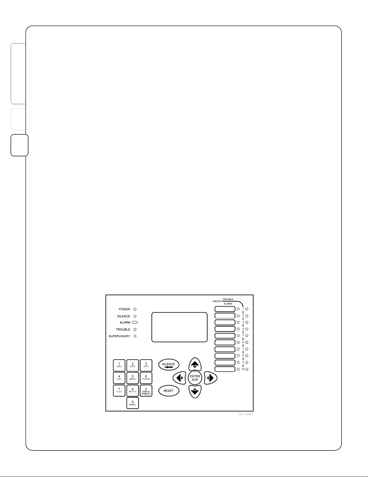
2.4 User control interface
System control and programming can be done through the LCD annunciator on the panel. The main
status display is an LCD screen with 8 line by 20 character text capability. Five system LEDs indicate
alarm (red), alarm silence (red), supervisory alarm (red), trouble (yellow), and AC power (green). Ten
zones of programmable alarm and trouble LEDs are located on the right hand side of the annunciator. A
piezoelectric sounder provides audible annunciation of off-normal indications. LCD remote annunciators
are similar and provide the same functionality as the panel’s local LCD annunciator.
Security is provided by a locking door or requiring activation of a keyswitch for most annunciator
commands. Maintenance and programming functions are further protected by passwords.
2.4.1 Resets
There are three types of resets available.
Fast reset
If all events qualify as resettable, i.e. the condition that triggered the event is no longer present, a fast
Figure 2-1. LCD annunciator
4
Page 9

HSI #780-0923 FireSpy Tracker Operation Manual
Button
Action (normal mode*)
ACK
SILENCE
RESET
PROG
reset will return the panel to its normal operating condition. To perform the fast reset, press the
button. The panel completes a fast reset in approximately 5-10 seconds.
Forced reset
The forced reset is similar to the fast reset, except that non-resettable events are forced to reset. To force
a reset, press and hold the
panel has restarted, it is likely that some events will reactivate because the condition that caused them is
still present. The panel completes a forced reset in approximately 5-10 seconds.
Full reset
The full reset powers down all circuits, even non-resettable circuits, during the reset. All modules perform
their startup initialization. To perform a full reset, press
RESET
. If you are in programming mode and press
completes a full reset in approximately 20-30 seconds, with SLCs completing their startup 10-20 seconds
after that.
RESET
button until the panel starts to reset (approx. 5 seconds). After the
PROG
to enter the passcode screen, then press
RESET
, this is the type of reset that occurs. The panel
Table 2-1: Annunciator Buttons
RESET
2
C D
A B
NOWLEDGE
Alphanumeric keypad
(other than 0)
* Refer to the programming sections of this manual and the programming manual for the programming mode functions of
the buttons.
Browse forward or backward through alarm event list
Browse forward or backward through the non-alarm event list
Turn off the annunciator’s buzzer
Turn off building notification and other outputs activated by off-normal events. The SILENCE LED
flashes when this button is activated.
Reset devices that are in alarm to a normal condition. See 2.4.1 for details.
Fast Reset: press RESET
Forced Reset: press and hold RESET
Full Reset: press PROG, then press RESET.
Used for programming only.
Enter the menu system.
3
4
5
A
B
5
Page 10

Contents
1
2
HSI #780-0923 FireSpy Tracker Operation Manual
2.5 System conditions and annunciation
2.5.1 Normal standby condition
Display
The system is considered to be in normal standby condition unless an offnormal condition or event occurs.
The log of previous events can be viewed from this screen by pressing
ENTER
press one of the arrow keys. To exit viewing the log, stop pressing
buttons until the display returns to the normal standby screen (about 45
seconds).
Audible and visual indicators
The buzzer is off, and all visual indicators are off, except for POWER,
which is on.
Available keys
ENTER
C D view next/prev alarm or supervisory alarm event in log
A B view next/prev trouble event in selected log
RESET
PROG/RESET
PROG
until the bottom of the screen shows Activity Journal and then
toggle which type of log to view (active or journal)
hold to perform forced reset
perform full reset
enter maintenance or programming menus
[BANNER MESSAGE 1]
[BANNER MESSAGE 2]
T1000 Vers 6.00
[date] [day] [time]
2.5.2 Non-normal condition (event counter)
Display
When there are active events, the display shows a counter for each type
of possible event. If an alarm is present, the lower portion of the display
will show information about the alarm event.
Audible and visual indicators
The buzzer sounds a pattern according to the highest priority event type
and the system LEDs corresponding to active events are turned on.
Available keys
SILENCE
ACK
(If all events are acknowledged) Toggle the list browsed by the
RESET
Press and hold to reset conventional zone alarm events.
To restart the panel, press
C / D Step backwards/forwards through the list of alarm/supervisory
A / B Step backwards/forwards in time through the Active Trouble list or
PROG
(If all events are acknowledged) Silence notification devices.
Acknowledge all events and turn off the buzzer.
right/left arrow keys (Active Troubles or Activity Journal).
Press once to reset alarm events.
PROG
and then
events
Activity Journal
Enter programming mode
RESET
.
Active Events
ALARM-0000 SUPV-0000
PRALM-0000 TBL-0001
(alarm present)
Active Events
ALARM-0001 SUPV-0000
PRALM-0000 TBL-0001
01/01/11 Su 12:00:00
001-Device in Alarm
Lobby Photo Smoke
6
Page 11

HSI #780-0923 FireSpy Tracker Operation Manual
2.5.3 Non-normal condition (browsing event list)
Display
After pressing A / B or C / D from a non-normal condition screen, the
display shows details of the most recent event.
The top left corner displays NR for return to normal, AL for alarm, TR for
trouble and pre-alarm, or SV for supervisory. The number following the
colon is the number of the event.
The top right corner shows the loop circuit number followed by the point
address.
The third line shows the event type -- a three digit event type code
followed by a textual description.
The display returns to the normal standby or the event counter screen if
an event occurs or after 45 seconds of inactivity.
Available keys
SILENCE
ACK
RESET
Press and hold to reset conventional zone alarm events.
To restart the panel, press
C / D Step backwards/forwards through the list of alarm/supervisory
A / B Step backwards/forwards in time through the Active Trouble list or
PROG
(If all events are acknowledged) Deenergize notification devices.
Return to the normal standby or event counter screen
Press once to reset alarm events.
PROG
and then
events
Activity Journal
Enter programming mode
RESET
.
TR:0075 02:0064
[date] [time]
037-Device Added
< Active Troubles >
2.5.4 Alarm condition
An alarm signal coming from an input device configured for an alarm function puts the panel into the
alarm condition. The outputs associated for that input are turned on and the panel’s buzzer sounds in the
alarm pattern. The alarm relay on the motherboard is activated. The ALARM LED turns on and the
display shows the non-normal screen.
2
3
4
5
A
B
2.5.5 Supervisory alarm condition
An alarm signal coming from an input device configured as a waterflow device puts the panel into the
supervisory alarm condition. The outputs associated for that input are turned on and the panel’s buzzer
sounds in the supervisory alarm pattern. The SUPERVISORY LED turns on and the display shows the
non-normal screen.
2.5.6 Trouble condition
A signal indicating a trouble from a device or the absence of a signal where one is expected puts the
panel into the trouble condition. The outputs associated for trouble conditions are turned on and the
panel’s buzzer sounds in the trouble pattern. The TROUBLE LED turns on and the display shows the offnormal screen.
2.5.7 Pre-alarm condition
The pre-alarm condition is a special type of trouble condition caused by a signal from an analog smoke
detector indicating that the detector is approaching an alarm level.
7
Page 12

Contents
HSI #780-0923 FireSpy Tracker Operation Manual
2.5.8 Programming mode
While the panel is in programming mode, the panel is still performing its normal monitoring functions. You
will need to reset the panel in order to review and address any events that occur while in programming
mode.
2.5.9 Other conditions
The fire drill test turns on building notification devices, output modules, and relay outputs according to
how they are programmed.
The walk test is a special operating mode. See 3.1.2 Walk test for details.
1
2.6 Features
2
2.6.1 Alarm Verification
The panel performs alarm verification on photo and ion intelligent smoke detectors(Apollo XP95 only).
The verification time is a global system program selection of 0 to 60 seconds.
2.6.2 Drift Compensation
The panel performs drift compensation on all addressable smoke detectors that don't have drift
compensation built in. Drift compensation counteracts changes in each detector's sensitivity over time.
Sensor drift is typically caused by dirt or dust in the sensing chamber (indicated by a positive drift value),
but it can also be caused by changes in the detector's electrical components due to long-term exposure to
harmful environmental conditions (a negative drift value). Drift compensation allows the panel to more
accurately determine the threshold for a genuine fire alarm, where a non-drift-compensated detector
under the same conditions would cause a nuisance alarm or an alarm to go unreported. However, there is
a maximum amount of drift that can be compensated. When the detector reaches the limit, it needs to be
serviced or replaced. The panel reports a trouble event when a detector reaches the drift limit.
The analog value that the panel displays for a detector is calculated from two numbers: the base value
(always 23) and the drift value (-15 to +15). A new or recently cleaned detector reports a raw analog
value of 23. The drift value is a long-time average of a detector's deviation from 23. For example, if a
detector reports a raw analog value of 28 for several weeks, it will eventually have a drift value of +5 (raw
value - base value = drift value, or 28 - 23 = +5). The panel will calculate a compensated value of 23 (raw
value - drift value = compensated value, or 28 - (+5) = 23). So the panel is able to use a consistent
numeric value over the long term serviceable operation of the detector.
2.6.3 Releasing
The panel provides 16 releasing circuits. The interface to a releasing device consists of a power source,
an Apollo / I-Spy input/output (IO) module, a URM relay, and a polarizing end-of-line device. The modules
needed for the releasing function are available pre-assembled and pre-wired in a cabinet. The power
source can be a NAC circuit on the Tracker panel set to continuous auxiliary power mode or any UL864
listed control unit with a power limited output rated Regulated 24 DC.
2.6.4 Smoke Control
The smoke control interface relies heavily upon the following items.
Fan and Damper Control Module (FDC)
An FDC is an SLC addressable output device that has timed supervisory functions needed for smoke
control operation. The FDC’s output controls a fan or damper and the input monitors the state of the fan
or damper. The first two of the FDC’s group slots are special “smoke control” groups, so sets of FDCs can
work in conjunction to turn on and turn off sets of HVAC components (intake and exhaust fans and
dampers). For example, to exhaust a floor, the FDCs controlling the exhaust fans and exhaust dampers
will turn on, while the FDCs controlling the intake fans and intake dampers will turn off.
8
Page 13

HSI #780-0923 FireSpy Tracker Operation Manual
Smoke detector control
Smoke detectors need to control both on and off states of fans and dampers in the building. This is
accomplished through group settings, FDC modules, and zone settings. Each smoke detector that
participates in smoke control is assigned to the special “smoke control” groups of several FDCs in order
to turn on and off the correct set of fans and dampers (e.g. two groups for “same floor”, two groups for
“floor above” and two groups for “floor below”).
Annunciation and control interface
The LDV provides outputs to drive lamps or LEDs which annunciate the status of fans and dampers in the
smoke control system. The LDV can also use switch inputs for manually controlling the smoke control
system.
Zones
Zone numbers are used to define the prioritization of actions. If an FDC is activated by multiple inputs in
its smoke control groups, the one that has the same zone number as the FDC takes precedence (a
“same floor” event takes precedence over a “floor above” or “floor below” event). Zone number 255 is a
special zone number which overrides all other zone numbers and provides a means for manual control.
Fully programming a system for smoke control can be very complex. Please refer to the smoke control
applications guide for more details.
2
3
4
5
A
B
9
Page 14

Contents
1
2
HSI #780-0923 FireSpy Tracker Operation Manual
This page left intentionally blank for duplex printing.
10
Page 15

HSI #780-0923 FireSpy Tracker Operation Manual
3 Test and maintenance
When any test or maintenance procedure is conducted, all building occupants and others who may
receive artificial alarms or trouble signals must be notified before starting and after completion.
These operations require entering the controlling annunciator into the maintenance mode with the
necessary password.
NFPA 72 and/or the authority having jurisdiction may have additional test and maintenance requirements
that must be followed.
NOTE On any system including remote signaling, the local fire department and/or
monitoring agency should be informed before any test or maintenance
functions.
3.1 System test
System test must be performed as required by the authority having jurisdiction. In the absence of other
instructions, test schedules for fire alarm systems are included in NFPA 72.
Tests should be performed in accordance with the manufacturer's instructions by qualified personnel, and
should be fully documented. The panel’s internal history provides a record of test functions that enter the
event list.
On completion of testing, ensure that all panel conditions have been reset or otherwise returned to
normal, and notify any agencies previously advised of the commencement of testing.
3
4
3.1.1 Initial acceptance testing
Refer to the Installation manual for details of initial acceptance testing.
3.1.2 Walk test
The panel includes the capability of one person making detector calibration tests on site, by either
momentarily sounding the notification appliances or just printing out results when pre-selected devices
are tested.
The silent walk test records the change of state of activated inputs for viewing or printing at the
completion of the test. When an input device is activated, only the buzzer on the annunciator sounds (not
any other output devices) in the pattern for the respective type of input.
The audible walk test additionally activates the outputs related to the activated input. Outputs related to
an alarm or supervisory alarm input are activated for approximately 2 seconds.
If no change of state is found for a period of 15 minutes during a walk test, the panel times out and
returns to a normal standby state.
Initiate the walk test from the annunciator (see 5.4 Menu 2.1: Normal Walk Test). Press
RESET
on the annunciator to end the walk test.
3.2 System maintenance
The Tracker system does not require regularly scheduled maintenance except that it is kept clean and
dry.
Check the sealed lead acid batteries occasionally for terminal corrosion and replace every four years or if
proper voltage is not maintained under load test.
SILENCE
or
5
A
B
11
Page 16

Contents
1
2
3
HSI #780-0923 FireSpy Tracker Operation Manual
Perform maintenance of any other system devices in accordance with the manufacturers' instructions.
3.2.1 Fuse replacement
WARNING To reduce the risk of electrical shock, make sure that all power has been
turned off or disconnected prior to disconnecting wiring or removing modules.
NOTE On any system that includes remote signaling, the local fire department
and/or monitoring agency should be informed before performing test or
maintenance functions.
If the system does not have power despite having sufficient line input voltage and battery voltage, a fuse
may need to be replaced. To check and replace the fuses, perform the following steps.
For T2000 and T8000:
1. Disconnect all power.
2. Disconnect wiring to the chassis assembly (MBC or MBCLC).
3. Remove the four nuts that secure the chassis assembly to the enclosure.
4. Remove the chassis assembly and turn it over.
5. Check the fuse on the T8000-PC board at location F1. If the fuse needs replacement, use a
standard automotive miniature fuse rated 15A (Littelfuse 997015 or equivalent).
6. Check the fuse on the RL9801 power supply at location F1. If the fuse needs replacement, use a
standard 5x20mm cartridge fuse rated T6.3AL250V (Littelfuse 021806.3 or equivalent).
For T1000:
1. Disconnect all power.
2. Check the fuse on the MB main board at location F1. If the fuse needs replacement, use a
standard automotive miniature fuse rated 15A (Littelfuse 99707.5 or equivalent).
3. Disconnect wiring to the chassis assembly (MB).
4. Remove the four nuts that secure the chassis assembly to the enclosure.
5. Remove the chassis assembly and turn it over.
6. Remove the power supply and the power supply’s metal cover.
7. Check the fuse on the LS100 power supply at location F1. If the fuse needs replacement, use a
standard 5x20mm cartridge fuse rated F4AH250V (Littelfuse 0216.004XEP or equivalent).
12
Page 17

HSI #780-0923 FireSpy Tracker Operation Manual
4 Using the menu system
4.1 Accessing the menu system
To access the menu system, press the
default code for Level 1 (maintenance functions) is 11111111. The default code for Level 2 (programming
functions) is 22222222.
The SLCs must finish their startup before the menu system can be accessed. The SLC startup takes 1030 seconds after the panel is reset.
4.2 Exiting the menu system
The changes you make are saved after you press
changes before exiting the menu system. To leave the menu system at any time, press
also reset the panel.
4.3 About the numbering used
Each menu in this manual is given a number based on how to navigate to it starting from the main menu:
• A number means press the number to select an option.
• A letter indicates which "more" screen the option is chosen from (A is the first screen, press C to get
to B, the second screen).
• Levels are separated by periods.
So to navigate to the Level 2 Menu 1.2B from normal standby press
Level 2), press 1 for child menu 1, press 2 for child menu 2, then press C to get to the second screen of
options.
PROG
key and enter the access code for the desired level. The
ENTER
on each screen. There is no extra step to save
RESET
PROG
(enter the passcode for
; this will
4
5
4.4 Menu navigation
Display
The display shows available menu options.
Available keys
0
to 9 go to child menu corresponding to number
E go back to parent menu
RESET
exit the menu system and reset the panel
4.5 Assign a setting
Display
When a screen shows some values to change, highlight the value you
wish to change and then change it.
Available keys
C / D: highlight the value you wish to change
A / B: change the highlighted value
E go back to parent menu
ENTER
RESET
go back to parent menu and save changes
exit the menu system and reset the panel
Program Menu
1. Clock
2. System Options
3. RS-485 Settings
4. Input Settings
5. Output Settings
6. Point Settings
7. Group Settings
Serial Port Config
Mode: PC Link
Dial Number:
Modem Init String:
A
B
13
Page 18

Contents
1
2
3
4
HSI #780-0923 FireSpy Tracker Operation Manual
4.6 Text and number entry
Entering text
Several places in the menu system ask for text to be entered.
Use alphanumeric keys to enter text. Press the key repeatedly until the
desired letter appears. Use A or B keys to move the cursor.
Example: To select the letter C, press the 1 (A B C) key three times.
Available keys
(for numerical entries)
0
- 9 enter a number
A / B move the cursor
(for alphanumeric entries)
0
- 9 cycle through the available characters for the key. Does not
advance cursor.
A / B move the cursor
E go back to parent menu
ENTER
RESET
go back to parent menu and save changes
exit the menu system and reset the panel
Banner Message
14
Page 19

HSI #780-0923 FireSpy Tracker Operation Manual
5 Maintenance menu
5.1 Level 1 main menu
The date format is yyyy.mm.dd.
The time format is hh:mm (24 hour time)
Available keys
0
to 9 go to child menu corresponding to number
E go back to parent menu
RESET
exit the menu system and reset the panel
5.2 Menu 1: Real time clock
The date format is yyyy.mm.dd.
The time format is hh:mm or hh:mm am/pm
Available keys
C / D highlight the value you wish to change
A / B change the highlighted value
E go back to parent menu
RESET
exit the menu system and reset the panel
Options:
1.Set Clock
2.Test Panel
Set Clock
Date: 2012.01.01
Time: 00:00
5.3 Menu 2: Test
Available keys
0
to 9 go to child menu corresponding to number
E go back to parent menu
RESET
exit the menu system and reset the panel
5.4 Menu 2.1: Normal Walk Test
While on this screen, devices that go into alarm are displayed on the
screen and the NACs sound a single round of alarm code.
Available keys
C / D browse through the items placed into alarm
E go back to parent menu
RESET
exit the menu system and reset the panel
Panel Test
1. Normal Walk Test
2. Silent Walk Test
3. NACs Outputs
4. Relay Outputs
5. LCD Display
6. Fire Drill
Walk Test Active
Press <SILENCE> to
end Walk Test
5
A
B
15
Page 20

Contents
2
HSI #780-0923 FireSpy Tracker Operation Manual
5.5 Menu 2.2: Silent Walk Test
While on this screen, devices that go into alarm are displayed on the
screen.
Available keys
C / D browse through the items placed into alarm
E go back to parent menu
RESET
exit the menu system and reset the panel
Walk Test Active
Press <SILENCE> to
end Walk Test
1
3
4
5
5.6 Menu 2.3: Test NACs
Available keys
C / D highlight the NAC you wish to test
A / B toggle testing on the highlighted NAC
E go back to parent menu
RESET
exit the menu system and reset the panel
5.7 Menu 2.4: Test Relays
Available keys
C / D highlight the relay you wish to test
A / B toggle testing on the highlighted relay
E go back to parent menu
RESET
exit the menu system and reset the panel
NAC Immediate On/Off
NAC1: OFF NAC2: OFF
NAC3: OFF NAC4: OFF
Relay Test
Trouble Relay: OFF
Alarm Relays: OFF
5.8 Menu 2.5: Test LCD Display
As soon as you enter this menu option, the PDC screen will alternately
turn all pixels on and all pixels off row by row and also turn all PDC LEDs
on and off.
Available keys
E go back to parent menu
RESET
exit the menu system and reset the panel
5.9 Menu 2.5: Drill Test
The drill test will activate all outputs that are configured to operate during
a fire drill.
Available keys
E go back to parent menu
RESET
exit the menu system and reset the panel
16
(alternately filled
and cleared)
<<< Fire Drill >>>
Press <SILENCE> to
end Fire Drill
Page 21

HSI #780-0923 FireSpy Tracker Operation Manual
Appendix A. Glossary
Terms used in this manual are defined as follows:
Acknowledge- An operator action indicating that an off-normal panel condition has been observed.
Alarm Signal- A signal indicating a fire alarm from a manual station, a waterflow alarm, or an automatic
smoke detector.
Alarm Silence Inhibit- An option that prevents silencing the notification appliances for a preset period of
time.
Alarm System- A system of compatible initiating devices, notification appliances, control panel, and
accessories assembled to provide warning signals and remote alarms in the event of a fire.
Alarm Verification- A programmable option that requires a repeated alarm signal from smoke detectors
before indicating an alarm.
Annunciator- A remote display, in communication with the control panel, indicating the status of an alarm
system.
Audible Signal- A sound made by audible notification appliances, such as bells or horns.
Authority Having Jurisdiction (AHJ)- The office or officer responsible for approving fire or safety
systems for the area or community involved.
Auto-Silence- The option by which a panel may automatically silence the notification appliances after a
preset time period time.
Auxiliary Relays- Relays used to energize or de-energize other equipment.
Class A Circuit- A circuit connected so that a single open or ground will not prevent its function. These
are NFPA Style 6 and Style 7 initiating device circuits and NFPA Style Z notification appliance circuits.
Class B Circuit- A circuit connected such that a single open or ground may prevent normal operation.
These are NFPA Style 4 initiating device circuits and NFPA Style Y notification appliance circuits.
Counting Zone- A configuration in which two detectors in a specified area must operate before the alarm
is recognized.
Detector – Ionization (Ion)- A smoke detector using the effect of smoke on the passage of current in an
ionized air chamber.
Detector – Photoelectric (Photo)- A smoke detector sensing reflection or obstruction of a light beam by
the smoke.
Digital Alarm Communications Transmitter (DACT)- A device by which off-normal conditions indicated
on the panel may be communicated to a remote location by dial-up telephone lines.
Drift Compensation- An algorithm applied to changes in a smoke detector’s sensitivity over time in order
to provide a stable level of sensitivity.
End Of Line (EOL)- A resistor or other electronic device terminating a supervised circuit, to allow
continuous monitoring of the connection.
Firefighter Ignore- A provision by which an authorized firefighter may disable detection points found to
be causing a false alarm. This will indicate a system trouble and require repair service.
5
A
B
17
Page 22

Contents
1
2
3
4
5
A
HSI #780-0923 FireSpy Tracker Operation Manual
General Alarm- Simultaneous operation of all the notification appliances on a system.
Ground Fault- A system trouble indicating appearance of a leakage resistance between any system
wiring and the system ground.
Initiating Device- Any manual or automatic device used to indicate an off-normal condition. This includes
manual pull stations, smoke detectors, heat detectors, and waterflow or tamper switches.
Initiating Device Circuit (IDC)- The circuit by which initiating devices communicate with the control
panel.
Labeled Equipment- Devices or materials, identified by an appropriate label which have been certified as
acceptable by a laboratory or agency recognized by the "authority having jurisdiction". This certifies that
the equipment complies with appropriate standards.
Listed Equipment- Devices or materials included in a list of conforming equipment published by a
laboratory or agency acceptable to the "authority having jurisdiction" and authorized to bear their label.
National Electrical Code (NEC)- A national standard for electrical system safety, published by the
National Fire Protection Association as NFPA standard 70.
Notification Appliance- An electrical device indicating system status, including bells, horns, strobe lights,
and speakers.
Notification Appliance Circuit (NAC)- The circuit by which notification appliances are connected to the
control panel.
Positive Alarm Sequence (PAS)- A process in which an off-normal response by a designated detector
alerts an attendant, who may, by acknowledging within 15 seconds, delay the general alarm for 3
minutes, giving time to investigate and reset the system, if desired.
Power Supply- The circuit in a fire alarm panel which provides system operating power, either derived
from the building supply or, in case of building power failure, from batteries maintained at full charge
during normal operation.
Pre-Alarm Signal- A signal from an analog smoke detector indicating that the detector is approaching an
alarm level.
Pre-Signal- A process by which an off-normal response by a designated detector initiates an alarm with
only selected notification appliances operating, and may be programmed to then sound a general alarm if
not silenced within a selected period of over a minute.
Signaling Line Circuit (SLC)- A circuit or path between any combination of circuit interfaces, control
units, or transmitters over which multiple-system input signals or output signals, or both, are carried.
Smoke Control- Integration between the fire alarm system and a building’s HVAC system (fans and
dampers) to prevent the spread of smoke and fire.
Style W- A Class B NAC configuration in which a circuit reports troubles from grounds, shorts, or opens,
but cannot operate the notification appliances with the abnormal condition.
Style X- A Class B NAC configuration in which a circuit reports troubles from grounds, shorts, or opens,
and can operate the notification appliances with a single open.
Style Y- A Class B NAC configuration in which a circuit reports troubles from grounds, shorts, or opens,
and can operate the notification appliances with a single ground fault.
18
Page 23

HSI #780-0923 FireSpy Tracker Operation Manual
Style Z- A Class A NAC configuration in which a circuit reports troubles from grounds, shorts, or opens,
and can operate the notification appliances with a single open and/or a single ground fault.
Style 4- A Class B signaling line circuit in which the circuit reports troubles on ground faults, shorts,
and/or opens, and can communicate an alarm with a single ground fault.
Style 6- A Class A signaling line circuit in which the circuit reports trouble on ground faults, shorts, and/or
opens, and can communicate an alarm with a single open or a single ground fault.
Style 7- A Class A signaling line circuit in which the circuit reports trouble on ground faults, shorts, and/or
opens, and can communicate an alarm with a single open, single ground, open and ground, or wire-towire short. This is the same panel connection as Style 6, with specialized isolation modules included in
the loop.
Supervisory Alarm- A signal initiated by operation of a supervisory device.
Supervisory Device- A device monitoring the status of a fire sprinkler system, such as gate-valve
closure, unacceptable water level, low water pressure switch, low temperature, or unready fire pump.
Trouble Signal- A signal indicating a condition which may threaten normal system operation, such as a
circuit break, ground, power or equipment failure.
Walk Test- A test mode in which pre-selected initiating devices may be operated and indicate operation
without alarming the system.
Waterflow Switch- An assembly constructed and installed to detect water flow from one or more
sprinkler heads in a sprinkler system, thereby initiating an alarm signal.
Zone- An area grouping of inputs in the control panel for purposes of ordering the desired response.
A
B
19
Page 24

Contents
2
3
HSI #780-0923 FireSpy Tracker Operation Manual
This page left intentionally blank for duplex printing.
1
4
5
A
20
Page 25

HSI #780-0923 FireSpy Tracker Operation Manual
Condition
Description and some common responses
Normal standby
Alarm
Trouble
Appendix B. Operating instructions
FireSpy Tracker Operating Instructions
Frame these instructions and place adjacent to the panel for ready reference
When the system is operating normally and there are no off-normal conditions, the
green AC POWER light is on and the display screen shows the banner message.
In case of alarm, the ALARM light flashes, the buzzer sounds, and display screen
shows the oldest alarm event. Audible and visual notification devices and remote
alarm signals operate.
To view alarm conditions:
Press C / D keys to browse through alarm events.
To silence the alarm:
WARNING: For Authorized Personnel Only
This will silence audible NACs and change panel indications to the alarm silenced
condition.
• Acknowledge the reported events by pressing
• Verify that no waterflow or other non-silenceable devices are involved.
• Wait until the alarm silence inhibit timer has expired, if in use.
• Press
To reset the panel:
Only after the alarm condition is cleared, press RESET to return the panel to standby
operation.
SILENCE
NOTE: Any normally-energized relay control devices operated
.
by the system may momentarily reverse on panel reset.
ACK
.
When the system detects a trouble, the TROUBLE light flashes, the panel buzzer
sounds, and the trouble event shows on the display screen.
If the trouble has not been cleared within 24 hours, the trouble display will return to
its initial condition and the buzzer will sound.
WARNING: Some trouble conditions may prevent response to a fire
alarm.
To view trouble conditions:
Press A / B keys to browse through trouble events.
To silence the trouble buzzer:
• Press
If service is required, contact the installer or local Harrington dealer below.
Name
Address
Phone/Fax
start.
ACK
to acknowledge. The buzzer will silence and the resound timer will
Page 26

HSI #780-0923 FireSpy Tracker Operation Manual
Harrington Signal Inc.
2519 4th Ave., P.O. Box 590, Moline, IL 61265
(800) 577-5758 ⋅⋅⋅⋅ (309) 762-0731 ⋅⋅⋅⋅ FAX (309) 762-8215
Because Lives, Property and Businesses Aren’t Fireproof.
www.harringtonfire.com
 Loading...