

Page 1

document rev
INSTRUCTION SHEET
Commercial Products Group
2519-4th Ave, Moline, IL61265
800.521.8219 : 800.225.4109
www.cpglifesafety.com
POWERTONE® SPEAKERSPOWERTONE® SPEAKERS
POWERTONE® SPEAKERS
POWERTONE® SPEAKERSPOWERTONE® SPEAKERS
SPHPSPHP
SPHP
SPHPSPHP
(With or without Strobe Warning Light)
SAFETY MESSAGE
People's lives depend on your safe installation, test, operation,
and maintenance of our products. Read, understand, and
follow all safety messages and instructions. Refer to "Safety
Messages for Equipment Used in Fire-Protective Signaling
Systems" and any other documentation shipped with equipment before performing any system related duty.
I. GENERAL.
These two PowerTone models are 25 Vrms and 70
Vrms, indoor/outdoor rated, selectable power output (0.5 to
15 watts) loudspeakers for use with fire alarm signalling
systems such as CPG’s PowerTone system. They are
designed to reproduce electronically generated warning
tones, which command rapid recognition, and full range
voice communication. They are suitable for use in areas
with high ambient noise levels. These speakers are equipped
with a blocking capacitor to allow use in supervised alarm
signalling systems. The PowerTone Model SPHP speaker
is also available with an optional 24VDC strobe light
attached. All strobes are listed by Underwriters Laboratories in their respective categories.
regarding the attached strobe and message label(s) attachment, refer
to Model V1971 strobe instruction sheet (CPG Part No. 2561088 or
2561090) or Model VST strobe instruction sheet (CPG Part No.
2561310). Model V1971 may be used outdoors when Model VW outdoor
kit is employed; otherwise, Model V1971 is for indoor use only. Model
VST may be used for indoor use only. Speaker projectors on all
models are adjustable and may be repositioned to obtain
desired sound distribution.
II. SPECIFICATIONS.
Operating 25 Vrms or 70 Vrms
Voltage
For additional information
256882 0209
III. INSTALLATION.
A.
Unpacking.
After unpacking the speaker, examine it carefully
for possible damage that may have occurred in transit. If
equipment has been damaged, immediately file a claim with
the carrier stating extent of damage. Carefully check all
shipping labels and tags for special instructions before
removing or destroying them.
B.
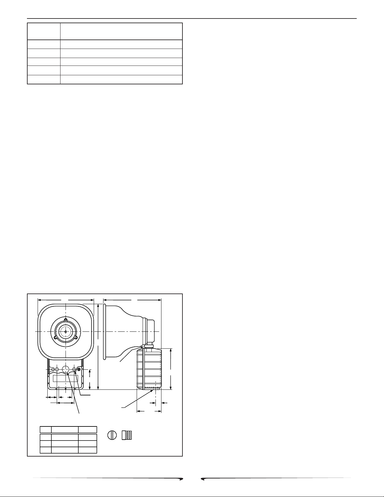
Mounting Arrangements (see figure 1).
The speaker can be mounted on any relatively flat
surface. Conduit connection can be made to two 1/2"
threaded openings at the bottom of the housing or to 7/8"
knockout in rear of housing. A 1/2" conduit plug is supplied
for field installation if one of the 1/2" threaded openings is
not utilized. After the mounting location and mounting
method have been selected, proceed with the applicable
instructions below.
WARNING
Property damage, serious injury, or death could occur if an
accumulation of water, snow, dust, etc. resides in the speaker
projector, severely reducing or preventing operation of this
device. Mount the unit so speaker projector is pointed horizontally or slightly downward.
1. Flat Surface Mounting
a. Remove and retain the two screws that
secure cover to housing. Remove the cover.
b. Select the mounting location and place
rear of housing against mounting surface.
C
Power Input 0.5 W, 1 W, 2 W, 7 W and 15 W
(selectable)
Weight 5 lb. (2.25kg)
(approx.)
Size 11-7/8" (302mm) high, 8-1/8" (206mm)
wide, 8" (203mm) deep.
Construction Aluminum enclosure painted with red
enamel. Amplifier housing sealed
with neoprene rubber gasket.
Approval Agency Listings:
Underwriters Laboratories Inc.
Model SPHP: File S6476(Guide UUMW
California State Fire Marshal—7230-1517:110
New York City—(Listing is pending.)
Audibility information is shown in table 1.
c . Using the mounting holes (two (2) inside
housing) as a template, scribe drill position marks on the
mounting surface. See figure 1 for mounting hole locations
and dimensions.
CAUTION
Before drilling holes in any surface, ensure that both sides of
surface are clear of items that could be damaged.
d. Secure the unit to a wooden mounting
surface with #10 x 1" wood screws. If mounting on a metal
surface, drill 13/64" diameter holes and secure the unit with
#10 screws, lockwashers and nuts.
e. Route power and supervision leads through
conduit to the audible signal. Install a 1/2" electrical connector at the bottom of the audible signal. Route wires through
conduit and electrical connector into the audible signal
- 1 -
Page 2
256882 SPHP Instruction Sheet
POWER UL SOUND LEVEL
TA P @ 10' dB(A)
0.5watt 87
1 watt 93
2 watt 96
7 watt 99
15 watt 102
Table 1. Power Tap Setting vs. Sound Output on
Model SPHP.
housing. Install supplied 1/2" conduit plug if only one 1/2"
conduit entrance is used.
WARNING
Property damage, serious injury or death could occur if the
projector is mishandled during installation or over time. DO
NOT rotate the projector more than 180 degrees or internal
speaker wiring may be damaged.
f . Reposition speaker projector if necessary
to obtain desired sound coverage. Loosen collar nut (see
figure 1) and move projector to desired position.
g. Before reinstalling the housing cover, read
paragraph III.C. Electrical Connections below and make the
necessary electrical connections.
2. Concealed Conduit Moounting.
a. Remove and retain the two screws that
secure cover to housing. Remove the cover.
b. Remove the 7/8" knockout at rear of hous-
ing.
c. Install the conduit connection.
AC
NOTE
If installation on an existing electrical box is desired, an optional
Model CC adapter plate is required.
d. Select the mounting location and place
rear of housing against mounting surface.
e. Using the two (2) mounting holes as a
template, scribe drill position marks on the mounting surface. See figure 1 for mounting hole locations and dimensions.
CAUTION
Before drilling holes in any surface, ensure that both sides of
surface are clear of items that could be damaged.
f. Secure the unit to a wooden mounting
surface with #10 x 1" wood screws. If mounting on a metal
surface, drill 13/64" diameter holes and secure the unit with
#10 screws, lockwashers and nuts.
WARNING
Property damage, serious injury or death could occur if the
projector is mishandled during installation or over time. DO
NOT rotate the projector more than 180 degrees or internal
speaker wiring may be damaged.
g. Reposition speaker projector if necessary
to obtain desired sound coverage. Loosen collar nut (see
figure 1) and move projector to desired position. Install two
1/2" conduit plugs in the unused bottom entryways (one
plug supplied).
h. Before reinstalling the housing cover, read
paragraph III.C. Electrical Connections below and make the
necessary electrical connections.
C.
Electrical Connections.
2-3/4
1-13/16
2-9/16
A
B
C
2
7/8 DIA. CONCEALED CONDUIT KNOCK OUT
MOUNTING (IN REAR OF HOUSING)
INCHES MM
8-1/8
11-7/8
8
.201 DIA. 2 HOLES
206
302
203
Figure 1. Model SPHP Speaker Dimensions.
B
COLLAR
NUT
(MOUNTING)
2 x 1/2-14 NPT
5-5/8
13/16
3-3/8
1/2" CONDUIT PLUG
SUPPLIED
290A2627-06A
National Electrical Code as well as local codes
must be adhered to in installation of these models. All
electrical wiring must be routed through approved conduit
and fittings.
1. Model SPHP (without Strobe Light Option).
a. See figures 2 and 3. Connect the audio
common (-) leads to the speaker’s common terminal and
audio positive (+) leads to desired wattage terminal.
WARNING
An uninsulated section of a single conductor must NOT be
looped around a terminal and used as two separate connections. NFPA 72 requires that the wire is severed to provide
electrical supervision of the connection.
b. See Figure 3. Connect the yellow lead,
found in the speaker, to the 25V or 70V terminal as
appropriate.
- 2 -
Page 3

256882 SPHP Instruction Sheet
290B2627-07
RED
24 VDC
STROBE
POWER
BLK
+
-
RED
BLK
RED
BLK
RED
25 OR 75 VRMS
SPEAKER
SIGNAL SOURCE
BLK
+
-
5
WARNING
Property damage, serious injury, or death could occur if the
housing is not closed properly.
c. Be sure the neoprene rubber cover gasket
is properly seated in the housing groove and reinstall the
housing cover.
2. Model SPHP (with Strobe Light Option).
DANGER
A high voltage shock hazard may be present inside the strobe
light, even if power is not connected. It is recommended that
strobe light NOT be opened. If access to the printed circuit
board assembly is required (removal or replacement of
damaged unit), disconnect unit from power source and wait
5 minutes.
a. See figure 2. Connect the strobe light’s red
(+) lead to the power source positive (+) lead. Connect the
strobe light’s black (-) lead to the power source negative () lead.
WARNING
IV . TESTING/OPERATING.
A. After installation is complete, be sure to test the
system to verify that each speaker and optional strobe light
operates satisfactorily. If it is found that the unit is too loud
for its location, a lower wattage tap may be selected.
Carefully remove the housing cover and move the positive
(+) lead to a lower wattage tap (see Figure 4). Reinstall the
housing cover and retest.
An uninsulated section of a single conductor must NOT be
looped around a terminal and used as two separate connections. NFPA 72 requires that the wire is severed to provide
electrical supervision of the connection. In addition, common
strobe leads must NOT be terminated within the same wire nut.
b. See figures 2 and 3. Connect the audio
common (-) leads to the speaker’s common terminal and
audio positive (+) leads to desired wattage terminal.
c. See figure 3. Connect the yellow lead,
found in the speaker, to the 25V or 70V terminal as
appropriate.
d. Be sure the neoprene rubber cover gasket
is properly seated in the housing groove and reinstall the
housing cover.
5W1W2W
COM
7W
15W
25V
70V
Figure 2. Typical Installation Wiring.
NOTE: LETTERS APPEAR ON THIS SIDE OF TERMINAL STRIP. SHOWN
HERE ON MOUNTING BRACKET FOR REFERENCE ONLY.
SPEAKER INTERNAL YELLOW LEAD TO BE CONNECTED TO 25V OR 70V
TERMINAL, DEPENDING UPON EXTERNAL SIGNAL SOURCE VOLTAGE.
YEL
POSITIVE (+) LEADS TO 1 OF 5 AVAILABLE WATTAGE TERMINALS.
COMMON (-) LEADS TO COMMON TERMINAL
290A335
Figure 3. Internal Multi-tap Wiring Set-up.
- 3 -
Page 4

256882 SPHP Instruction Sheet
WARNING
Property damage, serious injury, or death could occur if the
housing is not closed properly.
B . After completion of initial system test, establish a
program for periodic testing of this device. Refer to NFPA
72, local Fire Codes and the authority having jurisdiction for
this information.
WARNING
Unauthorized repair/servicing of the unit may result in degradation of performance and/or property damage, serious
injury, or death to you or others. If a malfunctioning unit is
encountered, do not attempt any field repair/retrofit of parts.
VI. SERVICE.
This product is covered by a 5 year warranty. See CPG
terms and conditions for more details.
C. Provide a copy of these instructions for the Safety
Engineer, system operator(s) and maintenance personnel.
V . MAINTENANCE.
A . Periodically check this device to verify that there
are no foreign substances in, or in front of, the speaker
which will reduce its effectiveness.
B . Testing should be periodically performed. Refer to
NFPA 72, local Fire Codes and the authority having jurisdiction for information.
C. In the event a volume adjustment or other repair is
required, be sure to refer to the Safety Message For
Maintenance Personnel before proceeding.
The factory will service your equipment or provide
technical assistance with any problem that cannot be
handled locally with satisfaction or promptness.
If any unit is returned to factory for repair, it can be
accepted only if we are notified by mail or phone in advance
of its arrival. Such notice should clearly indicate service
requested and give all pertinent information regarding nature of problem and, if possible, its cause.
Communications and shipments should be addressed
to:
Technical Service Department
Commercial Products Group
2519 - 4th Avenue
Moline, IL 61265
800.521.8219 • FAX 800.225.4109
PowerTone is a registered trademark of Commercial Products Group (CPG).
- 4 -
 Loading...