

Page 1

Commercial Products Group
document rev
2519-4th Ave, Moline, IL61265
800.521.8219 : 800.225.4109
www.cpglifesafety.com
INSTRUCTION SHEET
SPHHSPHH
SPHH
SPHHSPHH
POWERTONE® SPEAKERSPOWERTONE® SPEAKERS
POWERTONE® SPEAKERS
POWERTONE® SPEAKERSPOWERTONE® SPEAKERS
256885 0209
A
SAFETY MESSAGE TO INSTALLERS
People’s lives depend on your safe installation of our
products. It is important to read, understand and follow all
instructions shipped with this product. Listed below are
some other important safety instructions and precautions
you should follow:
• This unit must be installed by a qualified
electrician in accordance with NFPA 72, and
National and local Electrical and Fire Codes,
under the direction of the authority having
jurisdiction.
• Do not connect this unit to system wiring when
circuits are energized.
• For optimum sound distribution do not install
this device where objects would block any
portion of front of speaker.
• All effective warning speakers produce loud
sounds which, in certain circumstances, may
cause permanent hearing loss. Take appropriate precautions such as wearing hearing protection. Recommendations in OSHA Sound
Level Standard (29 CFR 1910) should not be
exceeded.
• After installation and completion of initial system test, a program for periodic testing of this
device must be established. Refer to NFPA 72,
local Fire Codes and the authority having
jurisdiction for this information.
• After installation and completion of initial system test provide a copy of this instruction sheet
to all personnel responsible for operation, periodic testing and maintenance of this equipment.
Failure to follow all safety precautions and instructions
may result in property damage, serious injury, or death to
you and others.
I. GENERAL.
The PowerTone Model SPHH is a 25 Vrms and 70
Vrms, indoor/outdoor rated, selectable power output (0.5 to
15 watts) loudspeaker for use with fire alarm signaling
systems such as CPG’s PowerTone system. It is designed
to reproduce electronically generated warning tones, which
command rapid recognition, and full range voice communi-
cation. It is suitable for use in areas with high ambient noise
levels. This speaker is equipped with a blocking capacitor
to allow use in supervised alarm signaling systems. The
PowerTone Model SPHH speaker is suitable for use in
Class I, Groups A, B, C, & D, Division 2; Class II, Groups
F & G, Division 2; and Class III hazardous locations. The
speaker projector is adjustable and may be repositioned to
obtain desired sound distribution.
II. SPECIFICATIONS.
Operating 25 Vrms or 70 Vrms
Voltage
Power Input 0.5 W, 1 W, 2 W, 7 W and 15 W
(selectable)
Weight 5 lb. (2.25kg)
(approx.)
Size 11-7/8" (302mm) high, 8-1/8" (206mm)
wide, 8" (203mm) deep.
Construction Aluminum enclosure painted with red
enamel. Amplifier housing sealed
with neoprene rubber gasket.
External mounting bracket on
Model SPHH.
Listings:
Underwriters Laboratories Inc.
Model SPHH: File E190743 (Guide UGKZ) Listed
as an "AUDIBLE SIGNAL DEVICE FOR USE IN
HAZARDOUS LOCATIONS".
Audibility information is shown in table 1.
III. INSTALLATION.
Unpacking.
A.
After unpacking the speaker, examine it carefully
for possible damage that may have occurred in transit. If
equipment has been damaged, immediately file a claim with
the carrier stating extent of damage. Carefully check all
shipping labels and tags for special instructions before
removing or destroying them.
B.
Mounting Arrangements (see figure 1).
CAUTION
To maintain the hazardous location rating of the
Model SPHH, do not use the 7/8" knockout (concealed conduit mounting).
- 1 -
Page 2
POWER UL SOUND LEVEL
TA P @ 10' dB(A)
0.5watt 87
1 watt 93
2 watt 96
7 watt 99
15 watt 102
Table 1. Power Tap Setting vs. Sound Output.
256885
SPHH Instruction Sheet
mum effectiveness, ensure that the front of the
speaker is clear of obstructions.
b. Select the mounting location and place
rear of housing against mounting surface.
c. Using the mounting holes (four (4) in external mounting bracket) as a template, scribe drill position
marks on the mounting surface. See figure 1 for mounting
hole locations and dimensions.
The speaker can be mounted on any relatively flat
surface. Conduit connection can be made to two 1/2"
threaded openings at the bottom of the housing or to 7/8"
knockout in rear of housing. A 1/2" conduit plug is supplied
for field installation if one of the 1/2" threaded openings is
not utilized. After the mounting location and mounting
method have been selected, proceed with the applicable
instructions below.
WARNING
Property damage, serious injury, or death could
occur if an accumulation of water, snow, dust, etc.
resides in the speaker projector, severely reducing
or preventing operation of this device. Mount the
unit so speaker projector is pointed horizontally or
slightly downward.
1. Flat Surface Mounting
a. Remove and retain the two screws that
secure cover to housing. Remove the cover.
WARNING
Property damage, serious injury, or death could
occur if any objects are in front of speaker, severely
reducing optimum sound distribution. For maxi-
AC
CAUTION
Before drilling holes in any surface, ensure that
both sides of surface are clear of items that could
be damaged.
d. Secure the unit to a wooden mounting
surface with #10 x 1" wood screws. If mounting on a metal
surface, drill 13/64" diameter holes and secure the unit with
#10 screws, lockwashers and nuts.
e. Route power and supervision leads through
conduit to the audible signal. Install a 1/2" electrical connector at the bottom of the audible signal. Route wires through
conduit and electrical connector into the audible signal
housing. Install supplied 1/2" conduit plug if only one 1/2"
conduit entrance is used.
WARNING
Property damage, serious injury or death could
occur if the projector is mishandled during installation or over time. DO NOT rotate the projector more
than 180 degrees or internal speaker wiring may be
damaged.
f . Reposition speaker projector if necessary
to obtain desired sound coverage. Loosen collar nut (see
figure 1) and move projector to desired position.
g. Before reinstalling the housing cover, read
paragraph III.C. Electrical Connections below and make the
necessary electrical connections.
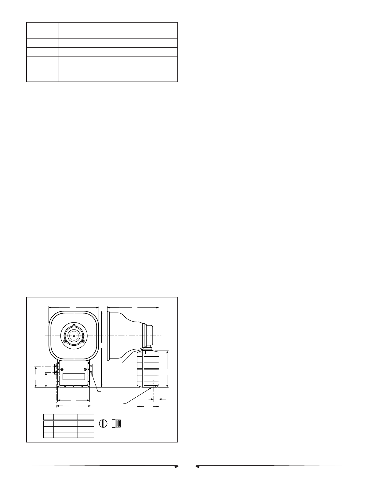
3-1/4
2-1/4
A
B
C
B
COLLAR
NUT
.201 DIA. 4 HOLES
5
5-1/2
INCHES MM
8-1/8
11-7/8
8
206
302
203
(MOUNTING)
1/2-14 NPT
Figure 1. Speaker Dimensions.
13/16
3-3/8
1/2" CONDUIT PLUG
SUPPLIED
290A2627-05C
5-5/8
C.
Electrical Connections.
DANGER
To avoid electrical shock, do not connect wires
when circuits are energized.
National Electrical Code as well as local codes
must be adhered to in installation of these models. All
electrical wiring must be routed through approved conduit
and fittings.
1. See figures 2 and 3. Connect the audio common (-) leads to the speaker’s common terminal and audio
positive (+) leads to desired wattage terminal.
- 2 -
Page 3

256885
WARNING
An uninsulated section of a single conductor must
NOT be looped around a terminal and used as two
separate connections. NFPA 72 requires that the
wire is severed to provide electrical supervision of
the connection.
2. See Figure 3. Connect the yellow lead, found
in the speaker, to the 25V or 70V terminal as appropriate.
SPHH Instruction Sheet
hear or heed your warning signal. You must recognize this fact and ensure that your warning signal
achieves its intended effect through proper test/
training sequences within your specific application(s).
V . MAINTENANCE.
SAFETY MESSAGE
TO
MAINTENANCE PERSONNEL
WARNING
Property damage, serious injury, or death could
occur if the housing is not closed properly. To
reduce possibility of explosion, the Model SPHH’s
housing cover must be kept tight while circuits are
energized.
3. Be sure the neoprene rubber cover gasket is
properly seated in the housing groove and reinstall the
housing cover.
IV . TESTING/OPERATING.
WARNING
Under certain conditions these devices are capable
of producing sounds loud enough to cause hearing
damage. Adequate hearing protection should be
worn if standing within close proximity to device
while testing. Recommendations in the OSHA
Sound Level Standard (29 CFR 1910) should not be
exceeded.
A. After installation is complete, be sure to test the
system to verify that each speaker operates satisfactorily.
If it is found that the unit is too loud for its location, a lower
wattage tap may be selected. Carefully remove the housing
cover and move the positive (+) lead to a lower wattage tap
(see Figure 3). Reinstall the housing cover and retest.
WARNING
Property damage, serious injury, or death could
occur if the housing is not closed properly. To
reduce possibility of explosion, housing cover must
be kept tight while circuits are energized.
B . After completion of initial system test, establish a
program for periodic testing of this device. Refer to NFPA
72, local Fire Codes and the authority having jurisdiction for
this information.
C. Provide a copy of these instructions for the Safety
Engineer, system operator(s) and maintenance personnel.
SAFETY MESSAGE TO OPERATORS
Even if your warning system is operating properly,
it may not be completely effective. People may not
Failure to follow all safety precautions and instructions
may result in property damage, serious injury, or death to
you or others.
• Read and understand all instructions before
performing maintenance on this unit.
• To reduce the risk of electrical shock or ignition
of hazardous atmospheres, do not perform
maintenance or service on this unit when
circuits are energized.
• Periodic checks should be made to ensure that
effectiveness of this device has not been
reduced because speaker has become clogged
with a foreign substance or because objects
have been placed in front of the speaker.
• Any maintenance to this unit MUST be performed by a trained electrician in accordance
with NEC guidelines and local codes.
• Never alter this unit in any manner. Safety in
hazardous locations may be jeopardized if
additional openings or alterations are made to
Model SPHH.
• The nameplates, which contain cautionary or
other information of importance to maintenance personnel, should not be obscured if
exterior of device is painted.
A . Periodically check this device to verify that there
are no foreign substances in, or in front of, the speaker
which will reduce its effectiveness.
B . Testing should be periodically performed. Refer to
NFPA 72, local Fire Codes and the authority having jurisdiction for information.
C. In the event a volume adjustment or other repair is
required, be sure to refer to the Safety Message For
Maintenance Personnel before proceeding.
WARNING
Unauthorized repair/servicing of the unit may result
in degradation of performance and/or property dam-
age, serious injury, or death to you or others. If a
malfunctioning unit is encountered, do not attempt
any field repair/retrofit of parts.
- 3 -
Page 4

256885
5
VI. SERVICE.
This product is covered by a 5 year limited warranty.
See CPG terms and conditions for details.
The factory will service your equipment or provide
technical assistance with any problem that cannot be
handled locally with satisfaction or promptness.
If any unit is returned to factory for repair, it can be
accepted only if we are notified by mail or phone in advance
of its arrival. Such notice should clearly indicate service
requested and give all pertinent information regarding nature of problem and, if possible, its cause.
Communications and shipments should be addressed
to:
Technical Service Department
Commercial Products Group
2519 - 4th Avenue
Moline, IL 61265
800.521.8219 • FAX 800.225.4109
PowerTone is a registered trademark of Commercial Products Group.
SPHH Instruction Sheet
RED
BLK
RED
BLK
SPEAKER
MODEL SPHH
END OF LINE DEVICE
+
RECOMMENDED BY
CONTROL UNIT
SUPPLIER
290A2627-08
5W1W2W
COM
7W
15W
25V
70V
Figure 2. Typical Installation Wiring.
NOTE: LETTERS APPEAR ON THIS SIDE OF TERMINAL STRIP. SHOWN
HERE ON MOUNTING BRACKET FOR REFERENCE ONLY.
SPEAKER INTERNAL YELLOW LEAD TO BE CONNECTED TO 25V OR 70V
TERMINAL, DEPENDING UPON EXTERNAL SIGNAL SOURCE VOLTAGE.
YEL
POSITIVE (+) LEADS TO 1 OF 5 AVAILABLE WATTAGE TERMINALS.
COMMON (-) LEADS TO COMMON TERMINAL
Figure 3. Internal Multi-tap Wiring Set-up.
- 4 -
290A335
 Loading...