

Page 1

39214-239/Issue 2
Functional Test Data
OUTPUT BIT FUNCTION INPUT BIT FUNCTION
2 ALARM LED 2 ALARM LED CONFIRMATION
1 = ON 1 = ON
0 = OFF 0 = OFF
1 REMOTE TEST 1 INDICATES WIRING CLASS
1 = TEST ENABLED 1 = CLASS B*
0 = NORMAL 0 = CLASS A
0 NOT USED 0 ALARM STATUS
1 = ALARM
0 = NORMAL
* Note: Toggles to ‘0’ in alarm.
Tec h nic a l Da t a
Monitored circuit
Current consumption
Quiescent 600µA
Alarm (LED on) 4.6mA
End-of-line supervisory resistance 47kΩ, 0.5W
Analog levels
Open-circuit fault 4
Normal 16
Alarm on switch closure 64
Compatibility Information
The I-Spy Mini Switch Monitor and I-Spy Mini Priority Switch Monitor modules have been
approved by Underwriters Laboratories Inc. for use with the Fire Spy
panel.
™ Tracker 8000 control
I-Spy Mini Switch Monitor Module and
I-Spy Mini Priority Switch Monitor Module
Installation Instructions
General
The I-Spy Mini Switch Monitor Module, par t no IS816, is a loop-powered device, which
incorporates a monitored input circuit for connection to switches. The module is supplied as
a small plastic housing designed to fit into an electrical box. Six flying leads of 18AWG are
used to connect the module.
A red LED flashes in synchronization with the current pulse reply from the device. If output
bit 2 is set the LED is illuminated continuously.
Harrington Signal Inc., 2519 4th Avenue, Moline, Illinois 61265, USA
© Apollo Fire Detector Ltd 2004
Tel: 800 577 5758 Fax: 309 762 8215
Website: www.harringtonfi re.com
4
The I-Spy Mini Priority Switch Monitor Module, part no IS815, has, in additon, a priority
interrupt facility to give fast response and can be fitted in an electrical box behind a pull
station.
Note: the I-Spy Mini Switch Monitor Module and the Mini Priority Switch Monitor Module are
not designed for outdoor use unless they are mounted in a suitable weatherproof enclosure.
Installation
1. The I-Spy Mini Switch Monitor Module and the I-Spy Mini Priorit y Switch Monitor Module
are not physically attached to the electrical box other than by means of the flying leads.
2. Connect the modules for Class A wiring or Class B wiring (Fig 2). Bit 8 of the DIL
switch is used to select the class of wiring. All wiring must conform to local codes and
regulations.
1
Page 2
Note
All circuits are power limited. Use only limited energy cable types FPL, FPLR or FPLP on
power limited circuits.
WIRING CLASS
0
ON
15432
76
8
A
6432168421
© Apollo Fire Detectors Limited 2004/JDR/JLC
Fig 1. Mounting the modules
RED
BLACK
VIOLET
YELLOW
GREEN
WHITE
I-SPY MINI SWITCH MONITOR
MODULE
© Apollo Fire Detectors LImited 2004/JDR/JLC
* Line 1 and Line 2 are polarity insensitive, but, for the sake of consistency it is recommended that Line 1 be kept negative.
LINE 2*
LINE 1*
Class A wiring
Class B wiring
VIOLET
YELLOW
GREEN
WHITE
47kΩ 0.5W EOL resistor connected internally across yellow and green wires
47kΩ
0.5W
EOL
Fig 2. Wiring Diagram for I-Spy Mini Switch Monitor and I-Spy Mini Priority
Switch Monitor Modules
1
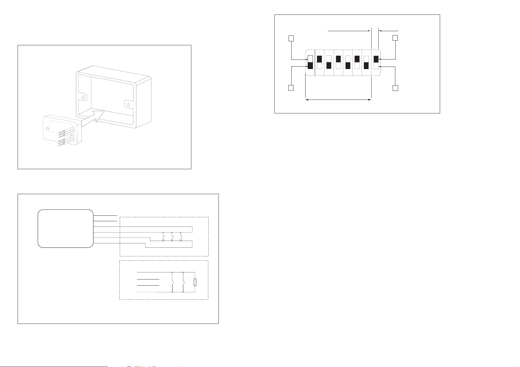
ADDRESS
B
© Apollo Fire Detectors Limited 2004/JDR
Fig 3. DIL Switch
Address Setting
Segments 1–7 of the DIL switch are used to select the address of the module. Each of the
seven segments must be set to ‘0’ (ON) or ‘1’ (OFF) using a small screwdriver or similar
tool. A complete list of address settings is shown below. (The eighth segment of the switch
is used to select Class A or B wiring.)
DIL switch DIL switch DIL switch DIL switch DIL switch
addr setting addr setting addr setting addr setting addr setting
1234567 1234567 1234567 1234567 1234567
1 1000000 11 1101000 21 1010100 31 1111100 41 1001010
2 0100000 12 0011000 22 0110100 32 0000010 42 0101010
3 1100000 13 1011000 23 1110100 33 1000010 43 1101010
4 0010000 14 0111000 24 0001100 34 0100010 44 0011010
5 1010000 15 1111000 25 1001100 35 1100010 45 1011010
6 0110000 16 0000100 26 0101100 36 0010010 46 0111010
7 1110000 17 1000100 27 1101100 37 1010010 47 1111010
8 0001000 18 0100100 28 0011100 38 0110010 48 0000110
9 1001000 19 1100100 29 1011100 39 1110010 49 1000110
10 0101000 20 0010100 30 0111100 40 0001010 50 0100110
51 1100110 61 1011110 71 1110001 81 1000101 91 1101101
52 0010110 62 0111110 72 0001001 82 0100101 92 0011101
53 1010110 63 1111110 73 1001001 83 1100101 93 1011101
54 0110110 64 0000001 74 0101001 84 0010101 94 0111101
55 1110110 65 1000001 75 1101001 85 1010101 95 1111101
56 0001110 66 0100001 76 0011001 86 0110101 96 0000011
57 1001110 67 1100001 77 1011001 87 1110101 97 1000011
58 0101110 68 0010001 78 0111001 88 0001101 98 0100011
59 1101110 69 1010001 79 1111001 89 1001101 99 1100011
60 0011110 70 0110001 80 0000101 90 0101101 100 0010011
101 1010011 111 1111011 121 1001111
102 0110011 112 0000111 122 0101111
103 1110011 113 1000111 123 1101111
104 0001011 114 0100111 124 0011111
105 1001011 115 1100111 125 1011111
106 0101011 116 0010111 126 0111111
107 1101011 117 1010111
108 0011011 118 0110111
109 1011011 119 1110111
110 0111011 120 0001111
2
3
 Loading...