

Page 1

Commercial Products Group
document rev
2519-4th Ave, Moline, IL61265
800.521.8219 : 800.225.4109
www.cpglifesafety.com
INSTRUCTION SHEET
FHEXFHEX
FHEX
FHEXFHEX
VIBRATONE® EXPLOSION-PROOF VIBRATORY HORNVIBRATONE® EXPLOSION-PROOF VIBRATORY HORN
VIBRATONE® EXPLOSION-PROOF VIBRATORY HORN
VIBRATONE® EXPLOSION-PROOF VIBRATORY HORNVIBRATONE® EXPLOSION-PROOF VIBRATORY HORN
256884 0209
A
SAFETY MESSAGE TO INSTALLERS
People’s lives depend on your safe installation of our products. It
is important to read, understand and follow all instructions shipped with
this product.
Selection of mounting location for this device, its controls and
routing of wiring should be made by the Facilities Engineer and the Safety
Engineer. Listed below are some other important safety instructions and
precautions you should follow:
• This unit must be installed by a qualified electrician in
accordance with NFPA 72, and National and local Electrical and Fire Codes, under the direction of the authority
having jurisdiction.
• Do not connect this unit to system wiring when circuits
are energized.
• For optimum sound distribution do not install this device
where objects would block any portion of front of speaker.
• All effective warning horns produce loud sounds which,
in certain circumstancs, may cause permanent hearing
loss. Take appropriate precautions such as wearing
hearing protection. Recommendations in OSHA Sound
Level Standard (29 CFR 1910) should not be exceeded.
• After installation, ensure that all bolts threaded joints are
tightened.
• After installation and completion of initial system test, a
program for periodic testing of this device must be
established. Refer to NFPA 72, local Fire Codes and the
authity having jurisdiction for this information.
• After installation and completion of initial system test
provide a copy of this instruction sheet to all personnel
responsible for operation, periodic testing and maintenance of this equipment.
Failure to follow all safety precautions and instructions may result
in property damage, serious injury, or death to you and others.
A. GENERAL.
The Vibratone Model FHEX is a hazardous location, intermittent
duty, polarized, 24 Volt dc, indoor/outdoor rated, high output, vibratory
horn for use with fire alarm systems. This model is suitable for use in
hazardous locations NEC Class I, Groups C, & D; Class II, Groups E,
F and G and has factory sealed leads.
B. SPECIFICATIONS.
Operating 24 Vdc
Voltage
Current 0.96A - 1.44 A
Duty cycle 5 min. on—5 min. off
Weight (approx.) 10 lb. (4.536kg)
Size 12" (305mm) high, 6-7/8"
Construction Heavy corrosion resistant cast
Approval Agency Listings:
Underwriters Laboratories Inc.
File E190785(Guide UJPX) Listed as a
HAZARDOUS LOCATION AUDIBLE
SIGNAL FOR FIRE ALARM SERVICE.
California State Fire Marshal—(Listing is pending.)
New York City—(Listing is pending.)
Audibility:
94 dBA, UL omni-directional sound pressure rating.
116 dBA, Sound Power measurement.
100 dBA on axis at 10' in Anechoic chamber.
C. INSTALLATION.
1.
Unpacking.
damage that may have occurred in transit. If equipment has been
damaged, immediately file a claim with carrier stating extent of damage.
Carefully check all shipping labels and tags for special instructions
before removing or destroying them.
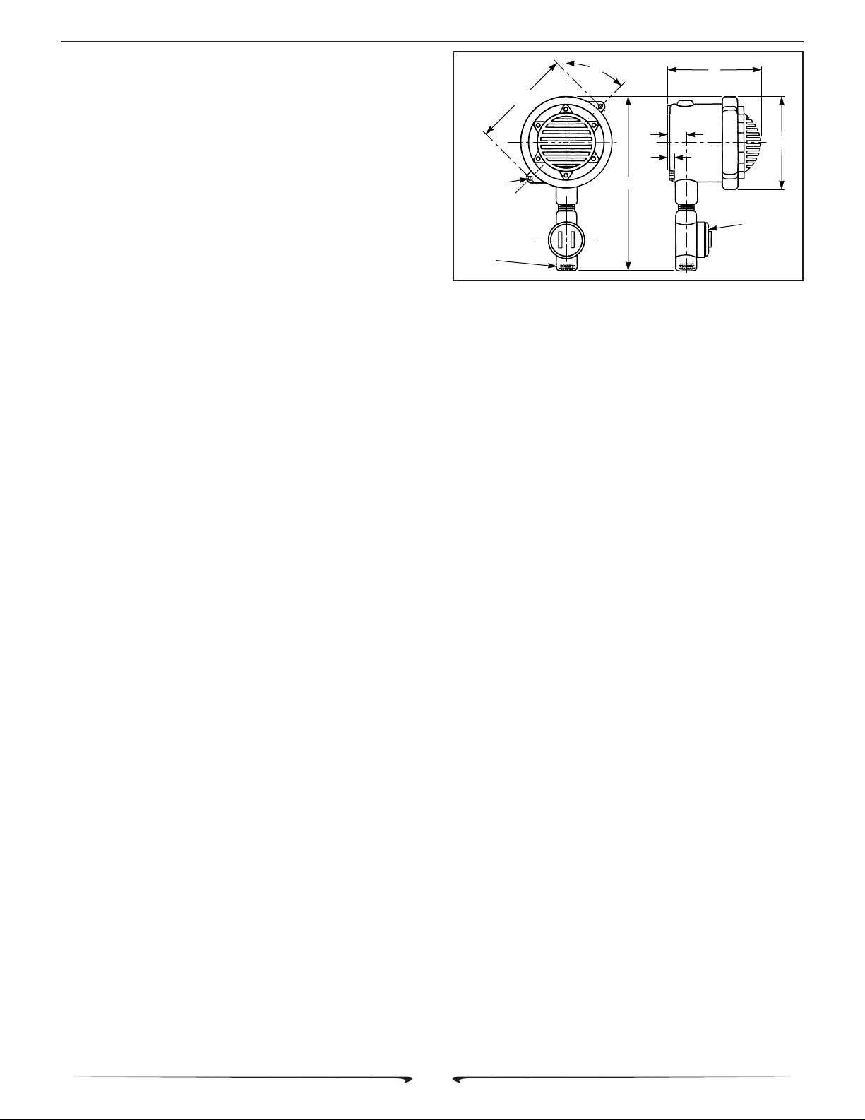
Conduit connection can be made to 3/4" threaded opening in splicing
condulet attached to this device (see figure 1).
After unpacking the horn, examine it carefully for possible
Property damage, serious injury or death could occur if this
product’s explosion-proof housing is damaged. The horn
mechanism contains no user serviceable parts. Therefore,
DO NOT loosen or remove clamp ring, which holds mechanism into housing, or any of the six screws on the front of the
horn grille. Loosening or removing any of these six screws
may disturb factory adjustment of horn mechanism and cause
the horn to malfunction. Attempting to remove the horn
mechanism from the horn housing may damage the horn
mechanism.
2.
Mounting Arrangements (see figure 1).
Property damage, serious injury, or death could occur if an
accumulation of water, snow, dust, etc. resides in the horn’s
grille, severely reducing or preventing operation of this device.
Mount the unit so the grille is pointed horizontally or slightly
downward.
This device can be mounted on any relatively flat surface.
(175mm) wide, 6" (152mm) deep.
aluminum enclosure.
Splicing condulet, tapped for 3/4"
conduit.
Stainless steel diaphragm.
Exterior painted with red enamel.
Leads factory sealed.
WARNING
WARNING
- 1 -
Page 2
256884
FHEX Instruction Sheet
WARNING
Property damage, serious injury, or death could occur if any
objects are in front of the horn’s grille, severely reducing
optimum sound distribution. For maximum effectiveness,
ensure that the front of the grille is clear of obstructions.
a. Select mounting location.
b. Using the horn as a template, scribe drill position marks
on the mounting surface. See figure 1 for mounting hole locations and
dimensions.
CAUTION
Before drilling holes in any surface, be sure both sides of
surface are clear of anything that could be damaged.
c. Drill holes at the previously scribed drill position marks
to accommodate 3/8" diameter bolts.
d. Secure the horn to the mounting surface with 3/8"
diameter hex head bolts, lockwashers, and hex nuts.
Electrical Connection.
3.
DANGER
To avoid electrical shock, do not connect wires when circuits
are energized.
MOUNTING
HOLE
CENTERS
13/32" DIA.
MOUNTING
HOLES (2)
3/4" I.P.S.
OUTLET
6-1/2"
45°
6"
7/8"
1/2"
12"
CONNECTIONS
Figure 1. Model FHEX Mounting Dimensions.
3. Provide a copy of these instructions for the Safety Engineer,
system operator(s) and maintenance personnel.
SAFETY MESSAGE TO OPERATORS
Even if your warning system is operating properly, it may not
be completely effective. People may not hear or heed your
warning signal. You must recognize this fact and ensure that
your warning signal achieves its intended effect through
proper test/training sequences within your specific
application(s).
6-7/8"
REMOVABLE
COVER FOR
WIRE
290A2627-22
adhered to in the installation of this device. All electrical wiring must be
National Electrical Code as well as local codes must be
routed through conduit and fittings approved for explosion-proof instal-
lations.
WARNING
Property damage, serious injury, or death could occur if
independent conductors are terminated together; both wires
of the same polarity must be used as two separate connections. NFPA 72 requires that the wires be terminated independently to provide electrical supervision of the connection.
a. Remove splicing condulet cover. See figure 2. Connect
the device’s red (+) leads to the power source positive (+) lead. Connect
the device’s black (-) leads to the power source negative (-) lead.
WARNING
Property damage, serious injury, or death could occur if the
condulet cover is not closed properly. To reduce the possibility
of explosion, splicing condulet cover must be kept tightly
closed while circuits are energized.
b. Replace splicing condulet cover and tighten.
D. TESTING/OPERATING.
WARNING
Under certain conditions these devices are capable of producing sounds loud enough to cause hearing damage. Adequate hearing protection should be worn if standing within
close proximity to device while testing. Recommendations in
the OSHA Sound Level Standard (29 CFR 1910) should not
be exceeded.
1. After installation is complete, be sure to test the system to
verify that each horn operates satisfactorily.
E. MAINTENANCE.
SAFETY MESSAGE
TO
MAINTENANCE PERSONNEL
Failure to follow all safety precautions and instructions may result
in property damage, serious injury, or death to you or others. People’s
lives depend on your safe maintenance of our products. Read and
understand all warnings in paragraph C. INSTALLATION. In addition,
listed below are some other safety messages and precautions you
should follow:
• Read and understand all instructions before performing
maintenance on this unit.
• Do not perform maintenance on this unit when circuits are
energized.
• Periodic checks should be made to ensure that effectiveness of this device has not been reduced because
speaker has become clogged with a foreign substance
or because objects have been placed in front of the
speaker.
• Any maintenance to this unit MUST be performed by a
trained electrician in accordance with NEC guidelines
and local codes.
• Never alter this unit in any manner. Safetyin hazardous
locations may be jeopardized if additional openings or
alterations are made to this device.
• The nameplates, which contain cautionary or other
information of importance to maintenance personnel,
should not be obscured if exterior of device is painted.
1. Periodically check this device to verify that there are no
foreign substances in, or in front of, the horn’s grille which will reduce
its effectiveness.
2. After completion of initial system test, establish a program for
periodic testing of this device. Refer to NFPA 72G, local Fire Codes and
the authority having jurisdiction for this information.
2. Testing should be periodically performed. Refer to NFPA
72G, local Fire Codes and the authority having jurisdiction for information.
- 2 -
Page 3

256884
FHEX Instruction Sheet
VIBRATORY
HORN
MODEL
FHEX
24 VDC
HORN POWER
RED(+)
(
-
)
BLK
RED
BLK
Figure 2. Typical Horn Installation Wiring.
WARNING
Unauthorized repair/servicing of the unit may result in degradation of performance and/or property damage, serious
injury, or death to you or others. If a malfunctioning unit is
encountered, do not attempt any field repair/retrofit of parts.
F. SERVICE.
The factory will service your equipment or provide technical
assistance with any problem that cannot be handled locally with
satisfaction or promptness.
If any unit is returned to factory for repair, it can be accepted only
if we are notified by mail or phone in advance of its arrival. Such notice
should clearly indicate service requested and give all pertinent information regarding nature of problem and, if possible, its cause.
Communications and shipments should be addressed to:
Technical Service Department
Commercial Products Group
2519 - 4th Avenue
Moline, IL 61265
800.521.8219 • FAX 800.225.4109
Vibratone is a registered trademark of Federal Signal
Corporation.
RED
BLK
RED
BLK
290A2627-23
END OF THE LINE DEVICE
RECOMMENDED BY
CONTROL UNIT SUPPLIER
- 3 -
 Loading...