

Page 1
EFFECTIVE: May 1, 2006
EFFECTIVE: May 1, 2006
Owner’s Manual
AIR
POWERED
CHAIN HOIST
TCR SERIES
MODEL TCR
10 Ton and 25 Ton Capacity
Code, Lot and Serial Number
WARNING
This equipment should not be installed, operated or
maintained by any person who has not read and understood
all the contents of this manual. Failure to read and comply
with the contents of this manual can result in serious bodily
injury or death, and/or property damage.
Page 2

Table of Contents
Section Page Number
1.0 Important Information and Warnings…………………………………………………………………4
1.1 Terms and Summary
1.2 Warning Tags and Labels
2.0 Technical Information………………………………………………………………………………… 8
2.1 Specifications
2.2 Dimensions
2.3 Part Names
3.0 Pre-operational Procedur es………………………………………………………………………... 12
3.1 Air Supply System Requirements
3.2 Air Supply Capacity And Regulation
3.3 Lubrication
3.4 Filtration
3.5 Air Dryer
3.6 Piping, Hoses And Fittings
3.7 Mounting Location
3.8 Connecting Hoist to Air Supply
3.9 Mounting the Hoist
3.10 Optional Chain Container
3.11 Non-Stationary Application
3.12 Preoperational Checks and Trial Operation
4.0 Operation……………………………………………………………………………………………. 19
4.1 Introduction
4.2 Shall’s and Shall Not’s for Operation
4.3 Hoist Controls
4.4 Adjusting the Controls
4.5 Operation of the Load Limiter
2
Page 3

Section Page Number
5.0 Inspection………………………………………………………………………….………………… 24
5.1 General
5.2 Inspection Classification
5.3 Frequent Inspection
5.4 Periodic Inspection
5.5 Occasionally Used Hoists
5.6 Inspection Records
5.7 Inspection Methods and Criteria
6.0 Lubrication…………………………………………………………………………………………... 31
6.1 Air Hoist Lubrication
6.2 Load Chain Lubrication
6.3 Hooks and Suspension Components
7.0 Maintenance & Handling…………………………………………………………………………… 32
7.1 Load Limiter
7.2 Brake
7.3 Load Chain
7.4 Pendant
7.5 Load Sheave Inspection
7.6 Storage
7.7 Outdoor Installation
8.0 Troubleshooting…………………………………………………………………………………….. 38
9.0 Warranty…………………………………………………………………………………………….. 40
9.0 Parts Information……………………………………………………………………………………. 41
3
Page 4

1.0 Important Information and Warnings
1.1 Terms and Summary
This manual provides important information for personn el involved with the insta llation, operation an d maintenance
of this product. Although you may be familiar with this or similar equipment, it is strongly recommended that you read
this manual before installing, operating or maintaining th e product.
Danger, Warning, Caution and Notice - Through out this manual there are steps and procedures that can pre sent
hazardous situations. The following signal words are used to identify the degree or level of hazard seriousness.
DANGER
WARNING
CAUTION
NOTICE
These general instructions deal with the no rmal installatio n, operation, and maint enance situation s encountered with
the equipment described herein. The inst ructions sh ould not be interp reted to anticipate eve ry possible co ntingency
or to anticipate the final system, crane, or configuratio n that uses this e quipment. For syst ems using the equipment
covered by this manual, the supplier and o wner of the syst em are responsible for the system’s compliance with all
applicable industry standard s, and with all app licable federal, state and local regulations/codes.
This manual includes instructions an d parts information for a v ariety of hoi st types. Therefore, all i nstructions an d
parts information may not apply to any one type or size of specific hoist. Disregard those portions of the instructions
that do not apply.
Danger indicates an imminently hazardou s situation which, if not avo ided, will result in death or
serious injury, and property damage.
Warning indicates an imminently hazardous situatio n which, if not avoided, could result in death or
serious injury, and property damage.
Caution indicates a potentially hazardous situation whi ch, if not avoided, may re sult minor or
moderate injury or property damage.
Notice is used to notify people of installation, operation, or maintenanc e information whi ch is
important but not directly hazard-related.
CAUTION
Record your hoist’s Code and Serial Number (see S ection 3.11.6 a nd Figure 10-1) on the front cov er of this manual
for identification and future reference to avoid refe rring to the wron g manual for inf ormation or instru ctions on
installation, operation, inspection, maintenance, or part s.
Use only Harrington authorized replacement pa rts in the servi ce and maintena nce of this hoist.
4
Page 5

WARNING
Equipment described herein is not designed for and MUST NOT
or for lifting or supporting loads over peop le.
Equipment described herein should not be used i n conjunction with other equi pment unless necessary and/ or
required safety devices applicable to the system, crane, or appli cation are instal led by the syste m designe r, system
manufacturer, crane manufacturer, installer, or user.
Modifications to upgrade, rerate, or otherwise alter this equipm ent shall be auth orized only by the ori ginal equipment
manufacturer.
Equipment described herein may be used in the desi gn and manufactu re of cranes or mon orails. Additional
equipment or devices may be required for the crane and monorail to comply with applicabl e crane design and safety
standards. The crane designer, crane manufactu rer, or user is respo nsible to furnish the se additional items for
compliance. Refer to ANSI/ASME B30.17, “Safety Standard for Top-Running Single Girder Cranes”; ANSI/ASME
B30.2 “Safety Standard for Top-Running Double-Girder Cranes”; and ANSI/ASME B30.11 “Safety Standard for
Underhung Cranes and Monorails”.
If a below-the-hook lifting device or sling is used with a hoist, refer to ANSI/ASME B30.9, “Safety Standard for
Slings” or ANSI/ASME B30.20, “Safety Standard for Below-the-Hook Lifting Devices”.
be used for lifting, supporting, or transporting people,
Hoists, trolleys and cranes, used to handle hot molten material may re quire additional equipment or devi ces. Refer to
ANSI Z241.2, “Safety Requirements for Melting and P ouring of Metals i n the Metalcasting In dustry”.
Failure to read and comply with any one of the limitation s noted herein can result in seriou s bodily injury or death,
and/or property damage.
5
Page 6

DANGER
HAZARDOUS AIR PRESSURE IS PRESENT IN THE HOIST, IN THE SUPPLY OF COMPRESSED AIR TO THE
HOIST, AND IN THE CONNECTIONS BETWEE N COMPONE NTS.
Before performing ANY maintenance on the equipment, de-energize the supply of compressed a ir to the
equipment, and lock and tag the supply device in the de -energized p osition. Refer to ANSI Z244. 1, “Personnel
Protection - Lockout/Tagout of Energy Sources.”
Only trained and competent personnel should i nspect and repair this equipment.
NOTICE
It is the responsibility of the owner/user to install, inspect, test, ma intain, and operate a hoist in accordance with
ANSI/ASME B30.16, “Safety Standard for Overhead Hoists”, OSHA Regulations. If the hoist is installed as part of a
total lifting system, such as an overhead crane or mono rail, it is also the respon sibility of the owner/user to compl y with
the applicable ANSI/ASME B30 volume that addresses that type of equipment.
It is the responsibility of the owner/user to have all personne l that will install, in spect, test, maint ain, and operate a
hoist read the contents of this manual and appli cable portions of ANSI/ ASME B30.16, “Safety Standa rd for Overhead
Hoists” and OSHA Regulations. If the hoist is installed as part of a total lifting system, such as an overhead cran e, the
applicable ANSI/ASME B30 volume that addresses that type of equipment must also be read by all personnel.
If the hoist owner/user requires additional information, o r if any information in the m anual is not clear, co ntact
Harrington or the distributor of the hoist. Do not inst all, inspect, test, maintain, or operate this hoist unless this
information is fully understood.
A regular schedule of inspection of the hoist in accordance with the requirements of ANSI/ASME B30.16 should be
established and records maintained.
6
Page 7
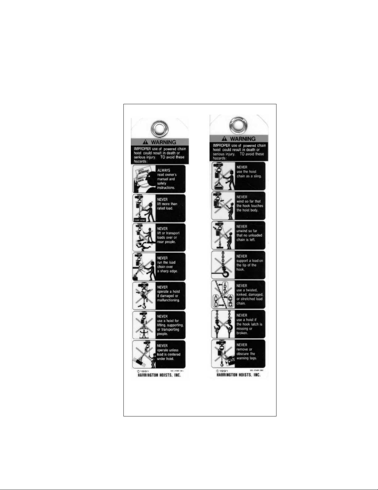
1.2 Warning Tags and Labels
The warning tag illustrated below in Figure 1-1 is supplied with each hoist ship ped from the factory. If the tag i s not
attached to your hoist (for pendant control, the warni ng tag is attached t o the pendant hose; for the pull cord control, the
warning tag is attached to the up cord), ord er a tag from you r dealer and install it. See parts li st in the parts section of
this manual. Read and obey all warnings attached to this hoist. Tag is not shown actual size.
front back
Figure 1-1 Warning Tag Attached to Air Hoist
7
Page 8
2.0 T echnical Information
2.1 Specifications
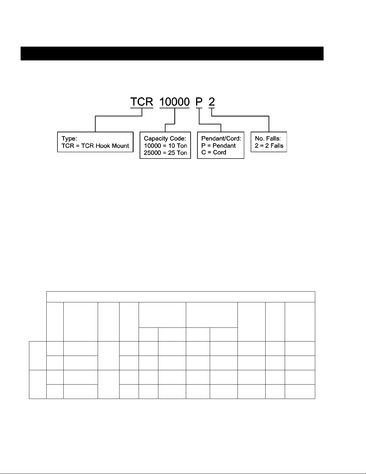
2.1.1 Product Code
2.1.2 Operating Conditions and E nvironment
Temperature range: +14° to +140°F (-10° to +60°C)
Relative Humidity: 85% or less
Supply Air: 60 to 90 pounds per square inch
Air Consumption: 170 to 220 cubic feet minute
Air Lubrication Requirements: Minimum 10 to 15 drops p er minute (2-3 cc/mi n) of oil
Air Filtration Requirements: Maximum 5 micron air filter or finer
Load Limiter: Adjustable; Factory set to 125% of rated capacity
Cap.
(Tons)
Product
Code
Standard
Lift
(ft)
Table 2-1 Hoist Specifications
Push
Button
Hose
(ft)
Up/Down Speeds
(ft/min @ 90 psi)
L
No Load w/Full Load No Load w/Full Load
Air Consumption Rates
(cubic ft/min @ 90 psi)
Up/Down
Load Chain
Diameter
(mm)
Chain Fall
Lines
x
Net
Weight
(lbs)
Weight for
Additional
One Foot
of Lift
(lbs)
10 TCR10000P2 8.8 7.2/5.9 5.1/7.6 220/180 180/210 16 x 2 476 3.8
Model
Pendant
25 TCR25000P2
10
9.4 2.1/1.6 1.8/2.2 210/190 170/200 22 x 2 1082 7.0
10 TCR10000C2 8.1 7.2/5.9 5.1/7.6 220/180 180/210 16 x 2 465 3.8
Cord
Model
25 TCR25000C2
10
8.7 2.1/1.6 1.8/2.2 210/190 170/200 22 x 2 1074 7.0
8
Page 9
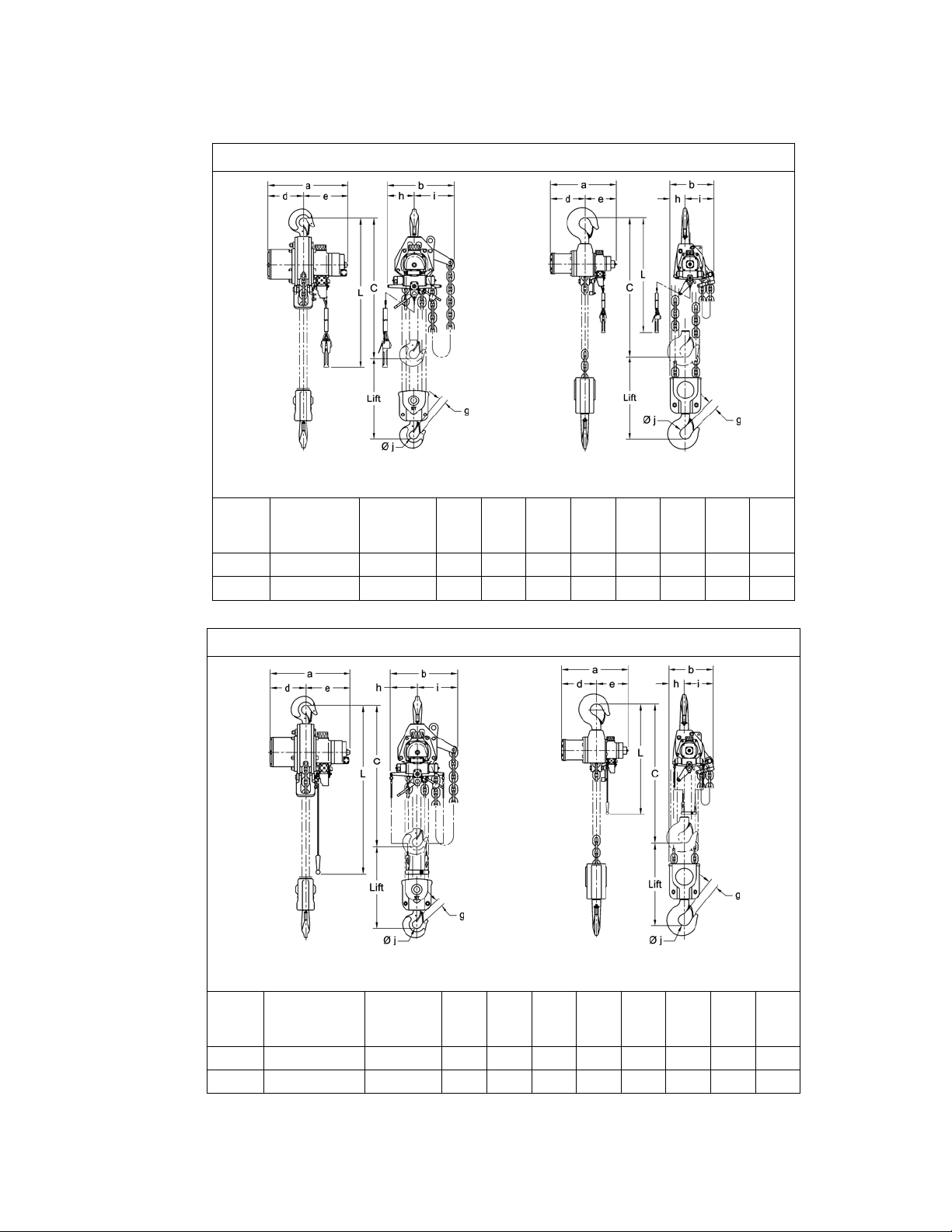
2.2 Dimensions
j
j
TCR10000P2 TCR25000P2
Table 2-2 TCR with Pendant Control Di mensions
Cap.
(Tons)
Product
Code
Headroom
C
(in)
(in)
a
b
(in)
d
(in)
e
(in)
g
(in)
h
(in)
(in)
i
(in)
10 TCR10000P2 35.0 21.7 18.4 9.7 12.0 1.6 7.4 11.0 2.4
25 TCR25000P2 56.7 27.5 18.7 14.3 13.2 3.1 6.4 12.3 4.9
TABLE 2-3 TCR WITH CORD CONTROL DIMENSIO NS
TCR10000C2 TCR25000C2
Cap.
(Tons)
Product
Code
Headroom
C
(in)
(in)
a
b
(in)
d
(in)
e
(in)
g
(in)
h
(in)
(in)
i
(in)
10 TCR10000C2 35.0 21.7 18.4 9.7 12.0 1.6 7.4 11.0 2.4
25 TCR25000C2 56.7 27.5 18.7 14.3 13.2 3.1 6.4 12.3 4.9
9
Page 10
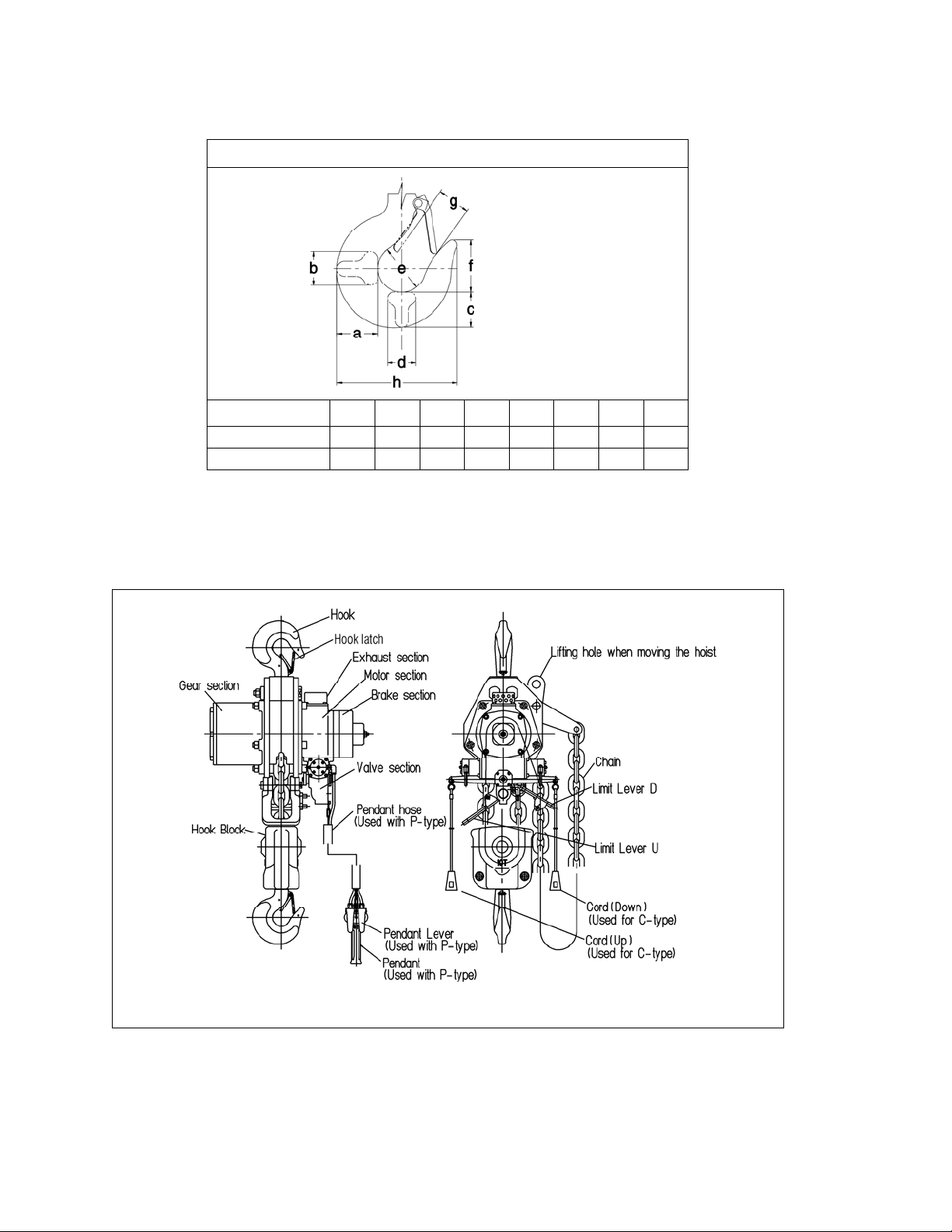
Table 2-4 Top and Bottom Hook Dimension*
Units = inch
Product Code a b c d e f g h
TCR10000C/P2
TCR25000C/P2
2.8 2.4 2.4 2.2 2.4 2.6 1.6 7.1
4.9 3.5 3.9 3.5 4.9 4.9 3.1 13.1
*Refer to Section 5.7 for inspection dimensions and limits.
2.3 Part Names
Figure 2-1 Hoist Part Identification Diagrams – 10 Ton TCR1 0000C2 a nd TCR10000 P2
10
Page 11
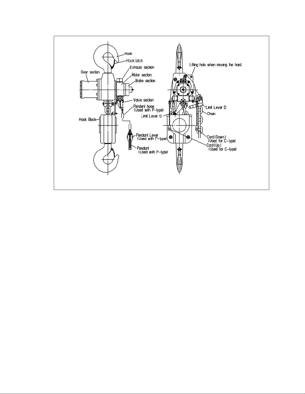
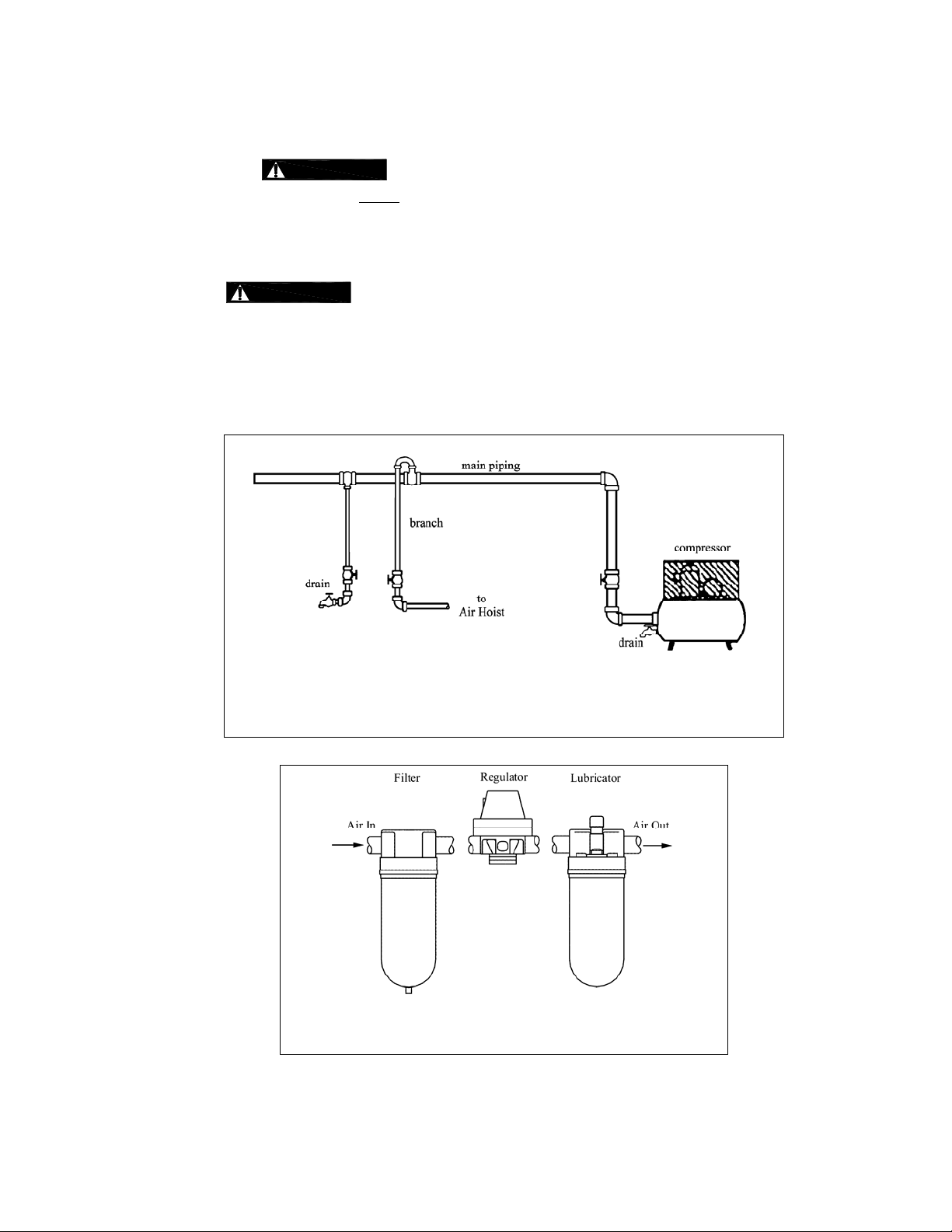
Figure 2-2 Hoist Part Identification Diagrams – 25 Ton TCR2 5000P2 and T CR25000C2
11
Page 12

3.0 Preoperational Procedures
3.1 Air Supply System Requirements
3.1.1
3.1.2
3.1.3
NOTICE
air hoist with required pressure and flow. Otherwise the hoist may operate poorly or may fail to
operate. See Section 3.2.
CAUTION
supply is the primary source of lubrication to the hoi st. Therefore, a dedicated air supply lubricator must
be used with the hoist. Refer to Section 3.3.
CAUTION
ensure its proper operation. The air must be clean and free of debri s such as dirt and rust. Refer to
Section 3.4 for filtration requirements. The air must al so be dry; free of moisture and wat er. Refer t o
Section 3.5.
Pressure and Flow - Verify that the air supply system has capacit y to supply your
Lubrication - The hoist requires lubricatio n for proper o peration. The oil in the ai r
Air Quality - Good air quality is essential to prevent dam age to your hoist a nd to
3.2 Air Supply Capacity And Regulation
3.2.1 Capacity - The air supply sy stem must be capable of deli vering the required airfl ow (cfm) to the hois t
inlet port. Without the required airflow the hoist will not operate prope rly or may not operate at all. See
Section 2.0 for your hoists air consumption re quirements. In dete rmining if your sy stem is capa ble of
supplying the required airflow, consider th e following:
Capacity of compressor(s) and tank
Other air consuming equipment
Flow restrictions such as pipes, hoses, v alves and f itting s
Inadequate capacity will cause a significant drop in pressure when the hoist i s operated, and co uld
cause poor performance or failure to operate.
3.2.2 Regulation - The hoist requires a con stant supply of air at a pressure of between 60 and 90 psi. If th e
air supply is not regulated or is regulated at a pressure greate r than 90 psi, then a regulator must be
used. The regulator may be located anywhere upline of the lu bricator in the air supply to the hoi st.
3.3 Lubrication
3.3.1
3.3.2
CAUTION
as follows:
1) Best location - At the hoist inlet. In this case the lubri cator can be either the mist type or drop
type.
2) Second best location - No more than 15 feet away from the hoist, at the same el evation or
above the hoist inlet. In this case the mist type lubri cator must be used.
3) Third best location - No more than 15 feet away below the hoist. In this case the mist type
lubricator must be used.
CAUTION
minute (2 to 3 cc/minute). The hoist’s exhaust will emit a fine oil mi st when properly lubricated.
3.4 Filtration
3.4.1
CAUTION
microns in size. Therefore, the hoist must have a 5 mi cron filter
upstream of the lubricator.
The hoist must be supplied with its own lubri cator. The lubri cator must be located
The lubricator must be set to deliver the equivale nt of 10 to 15 drops of oil per
The air entering the hoist inlet must not contain any p articulate great er than 5
in its air supply. The filter must be
12
Page 13
3.4.2 The filter servicing the hoist can also service othe r hoists and air consuming equip ment. In this case,
the air filter must be in sized for the total air con sumption of the equi pment it is servicing.
3.5 Air Dryer -
supply system to ensure that dry air
this moisture will cause corrosion on internal hoist components during periods when the hoist is idl e leading to
hoist malfunction.
CAUTION
3.6 Piping, Hoses And Fittings
3.6.1
CAUTION
Since moisture tends to accumulate in compressed air systems, corrosion may re sult if the system is
not periodically drained.
Arrange for a drain in the air supply piping at the lowest point in the piping, and
Periodically drain the system to remove moisture/water from the system and to prevent co rrosion.
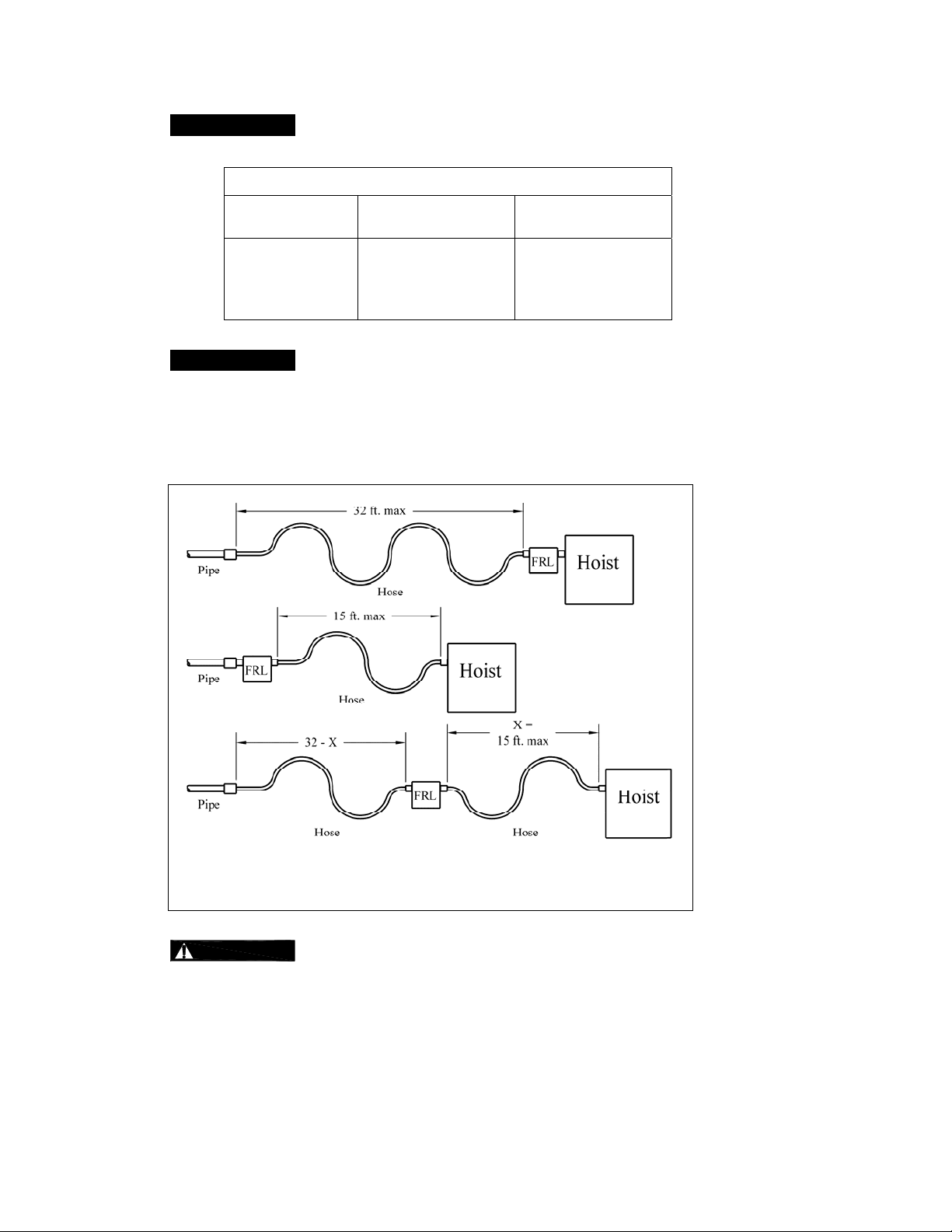
Filter, regulator (if equipped), and lubricator must be arranged in the ord er shown in Figure 3 -2.
System Configuration - The system should be configured as sh own in Figure 3-1.
To prevent corrosion and hoist malfun ction, employ an air dryer in the air
is supplied to the hoist. If there is moisture in the air supplied to the hoist,
Figure 3-1 Diagram of Air Supply Configuration (Ty pical)
Figure 3-2 Typical Air Supply Filter, Regulator and Lub ricator.
13
Page 14
3.6.2
3.6.3
NOTICE
Piping - Pipe should be sized to accommodate the hoi st airflow requi rements.
Table 3-1 gives recommended pipe si zes.
Table 3-1 Air Supply Pipe and Hose Sizes
Model
Diameter of Supply
Pipe
Diameter of Supply
Hose
TCR10000P2
TCR25000C2
TCR10000P2
Inside diameter
1.25 inch or larger
Inside diameter
1.0 inch or larger
TCR25000C2
NOTICE
Hoses - The connection from the ai r supply system piping to the hoi st must be
made with a flexible pressure hose. Due to normal li ne losses in air su pply lines:
Do not use hose smaller than specified in Table 3-1, and
Limit the length of the hose to that specified in Figure 3-3.
If your application exceeds these requirements consult factory.
3.6.4
Figure 3-3 Typical Arrangements of Filter, Regulator an d Lubricator and
Maximum Air Supply Hose Lengths
CAUTION
Fittings - Important considerations regarding fitting s in the hoist's ai r supply
include:
When connecting air supply components, remove all dirt or debris from the con necting surfa ces of
the hoses, pipes, fittings, or threaded fasteners to prevent contaminants from entering the hoist.
Keep airflow restrictions such as quick disconnect fittings, bends, elb ows, and adapters to a
minimum.
14
Page 15
3.6.5
CAUTION
purging procedures to prevent contaminants or moist ure from enteri ng the hoist.
Before connecting the hoist to its air supply line; perf orm the proper d raining and
3.7 Mounting Location
3.7.1
3.7.2
WARNING
are adequate to support the hoist and its loads. If ne cessary consult a p rofessional tha t is qualified to
evaluate the adequacy of the suspension location and its supp orting structure.
NOTICE
Prior to mounting the hoist ensure that the suspension and it supp orting structure
See Section 7.6 for outdoor installation considerations.
3.8 Connecting Hoist to Air Supply
3.8.1
WARNING
OF COMPRESSED AIR TO THE HOIST, AND IN THE CONNECTIONS BETWEEN COMP ONENTS.
HAZARDOUS AIR PRESSURE IS PRESENT IN THE HOIST, IN THE SUPPLY
3.8.2 Shut off the air supply and stop th e airflow compl etely. Lock out and tag out in a ccordance with ANSI
Z244.1 “Personnel Protection -Lockout/Tagout of Energ y Sources”.
3.8.3
3.8.4 Apply approximately 10-15 drops of turbine oil (see approved lub ricant under Section 6.0 Lubricants)
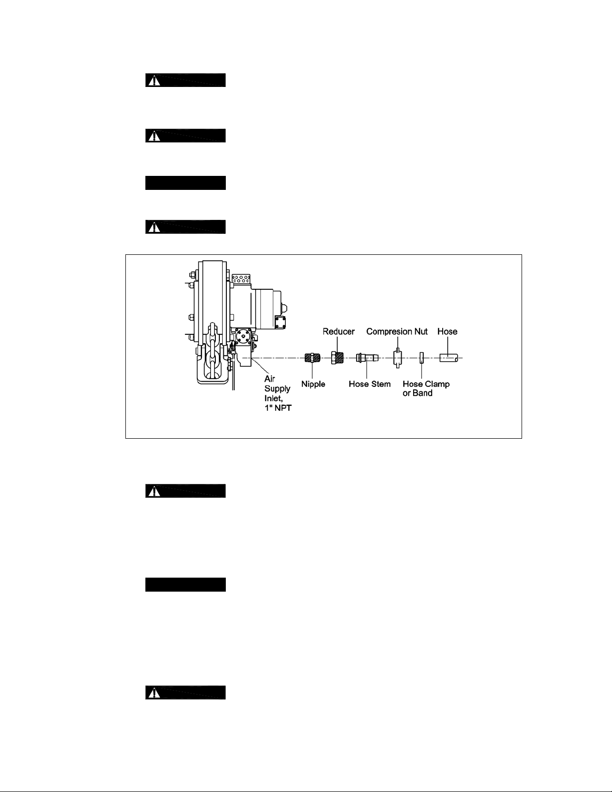
3.8.5 Make connection s to air supply; ref erence Figure 3-4. Use a red ucing adapter at the hoi st valve
3.8.6
CAUTION
clear any debris and water.
into the hose before attaching to the hoist.
section for hose sizes larger t han 1 inch.
NOTICE
the hoist first (Section 3.9) followed by connecting the air supply (Section 3.8).
3.9 Mounting the Hoist
3.9.1 Manual Trolley - Follow instructi ons in Owner’s Ma nual provided with t he trolley.
3.9.2 Motorized Trolley - Follo w instructions i n Owner’s Manual provided with the trolley.
3.9.3 Hook Mounted to a Fixed Location - Attach the hoist’s top hook to the fixed suspension point.
3.9.4
WARNING
that the hook’s latch is engaged .
Figure 3-4 Typical Air Supply Connection
Before connecting the air supply hose to the hoist, always purge the ai r hose to
Where conditions dictate, the installation sequen ce can be reversed by mounti ng
Ensure that the fixed suspension point re sts on t he cente r of the h ook’s sad dle and
15
Page 16
3.10 Non-Stationary Application
3.10.1 For applications such as rental fleets or construction sites where the hoist is moved from place-toplace, a filter and lubricator are still required. Consult factory for recommended meth ods.
3.10.2 Connections and fittings must be kept clean and care taken to prevent dirt, debris and moisture from
entering the hoist.
3.10.3 Recommended practice for removing the hoist fro m an installation:
Run the hoist briefly with well lubricated air
Disconnect the air supply line
Inject a small quantity (approximately 20 drops) of oil into the hoist’s inlet port
Plug the inlet port
3.11 Preoperational Checks and Trial Operation
3.11.1
3.11.2
CAUTION
Check for the availability of required operating air pressure of between 60 PSI to
90 PSI at the hoist's inlet port before trying to operate the hoist.
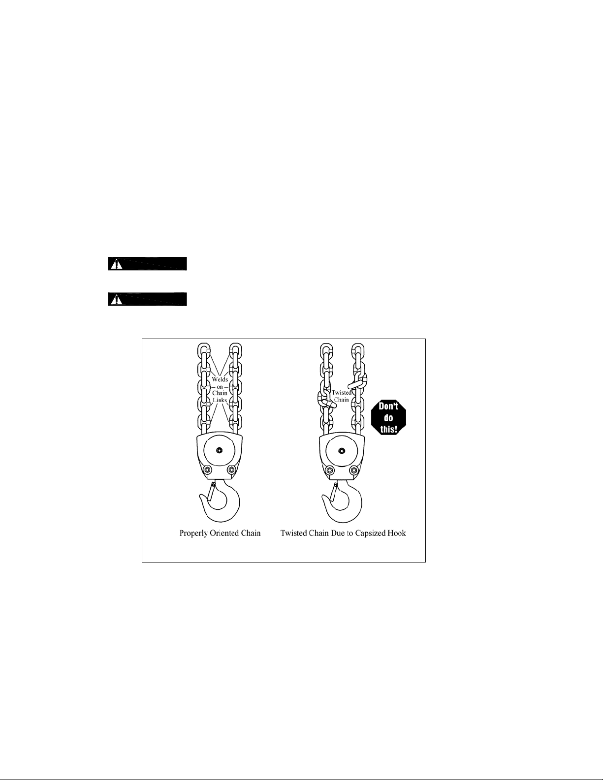
WARNING
Verify that the load chain is not twisted or tangled and that the bottom hook is not
capsized prior to operating the ho ist. Correct all chain irregularities before conducting the first hoist
operation. See Figures 3-5 and 3-6.
Figure 3-5 Twist in Load Chain
16
Page 17
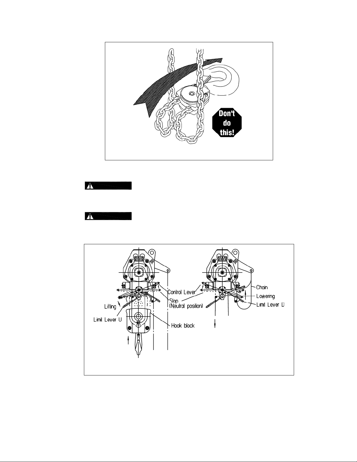
Figure 3-6 Capsized Hook and Chain
3.11.3
3.11.4
WARNING
Confirm the adequacy of the rated capacity for all slings, chains,
wire ropes and all other lifting attachments before use. Inspect all load suspension
members for damage prior to use and replace or repair all damaged parts.
WARNING
Verify that the Chain/Limit Levers are operational and can move
freely in both the up and down directions. For reference see Figure 3-7.
Figure 3-7 Limit Switch Components – 10 Ton T CR10000C2 and T CR10000P2
17
Page 18

Figure 3-8 Limit Switch Components – 25 Ton T CR25000C2 and T CR25000P2
3.11.5 Measure and record the “K” dimension of all hooks on hoist. See Table 5-6 under Section 5,
“Inspection”. Always use the same side of the hoo k to measure and record th e "K" dimension.
3.11.6 Record the hoist Code Number and Serial Num ber (fro m the namepl ate on the h oist – see Secti on 10)
in the space provided on the cover of this manual.
3.11.7 Ensure that the hoist is properly installed to either a fixed point, or trolley, whic hever applies.
3.11.8 If hoist is installed on a trolley, ensure th at
trolley is properly installed on the beam, and
stops for the trolley are correctly positioned and securely installed on the beam.
3.11.9 Ensure that all nuts, bolts and split (cotter) pins are sufficiently fastened.
3.11.10 For hoists with pendant controls , Ensure that the Pe ndant Hoses and Strain Relief Chain are pr operly
attached to the hoist. See Section 7.4.
3.11.11
CAUTION
Check Air Supply - Check air supply before everyday use. Ensure proper air
quality and air pressure.
3.11.12
CAUTION
Check the lubricator for proper function an d adequate oil level.
3.11.13 Confirm proper operation.
Before operating read and become familiar with Section 4 - Operation.
Before operating ensure that the hoist (and trolley) meets the Inspection, Testing and Maintenan ce
requirements of ANSI/ASME B30.16.
Before operating ensure that nothing will interfere with the full range of the hoist’s (and trolley’s)
operation.
3.11.14 Proceed with trial operation to confi rm proper oper ation.
Initially operate slowly under no load in both directions. Verify controls agree with ho ist direction.
Perform inspections per Section 5.3, “Frequent Inspections”.
18
Page 19

4.0 Operation
4.1 Introduction
DANGER
DO NOT
WALK UNDER A SUSPENDED LOAD
WARNING
HOIST OPERATORS SH ALL BE REQUIRED TO READ THE OPERATION SECTION OF THIS MANUAL, THE
WARNINGS CONTAINED IN THIS MANUAL, INSTRUCTION AND WARNING LABELS ON THE HOIST OR
LIFTING SYSTEM, AND THE OPERATION SECTIONS OF ANSI/ASME B30.16 and ANSI/ASME B30.10. THE
OPERATOR SHALL ALSO BE REQUIRED TO BE FAMILIAR WITH THE HOIST AND HOIST CONTROLS
BEFORE BEING AUTHORIZED TO OPERATE THE HOIST OR LIFTING SYSTEM.
HOIST OPERATORS SHOULD BE TRAINED IN PROPER RIGGING PROCEDURES FOR THE ATTACHMENT
OF LOADS TO THE HOIST HOOK.
HOIST OPERATORS SHOULD BE TRAINED TO BE AWARE OF POTENTIAL MALFUNCTIONS OF THE
EQUIPMENT THAT REQUIRE ADJUSTMENT OR REPAIR, AND TO BE INSTRUCTED TO STOP OPERATION
IF SUCH MALFUNCTIONS OCCUR, AND TO IMMEDIATELY ADVISE THEIR SUPERVISOR SO CORRECTIVE
ACTION CAN BE TAKEN.
HOIST OPERATORS SHOULD HAVE NORMAL DEPTH PERCEPTION, FIELD OF VISION, REACTION TIME,
MANUAL DEXTERITY, AND COORDINATION.
HOIST OPERATORS SHOULD NOT
PHYSICAL CONTROL, PHYSICAL DEFECTS, OR EMOTIONAL INSTABILITY THAT COULD RESULT IN
ACTIONS OF THE OPERATOR BEING A HAZARD TO THE OPERATOR OR TO OTHERS.
HOIST OPERATORS SHOULD NOT
INFLUENCE OF ALCOHOL, DRUGS, OR MEDICATION.
OVERHEAD HOISTS ARE INTENDED ONLY FOR VERTICAL LIFTING SERVICE OF FREELY SUSPENDED
UNGUIDED LOADS. DO NOT
ARE NOT FREELY SUSPENDED, OR LOADS THAT ARE GUIDED.
USE HOIST FOR LOADS THAT ARE NOT LIFTED VERTICALLY, LOADS THAT
HAVE A HISTORY OF OR BE PRONE TO SEIZURES, LOSS OF
OPERATE A HOIST OR LIFTING SYSTEM WHEN UNDER THE
NOTICE
• Read ANSI/ASME B30.16 and ANSI/ASME B30.10.
• Read the hoist manufacturer’s Operating and Mai ntenance Instructi ons.
• Read all labels attached to equipment.
19
Page 20

The operation of an overhead hoist involves more than activating the hoist’s controls. Per the ANSI/ASME B30
standards, the use of an overhead hoist is subject to certain hazards that cannot be mitigated by engineered features,
but only by the exercise of intelligence, care, common sense, and experience in anticipating the effects and results of
activating the hoist’s controls. Use this guidance in conjun ctio n with ot her wa rnings, ca utions, and notices in thi s manual
to govern the operation and use of your overhead hoist.
4.2 Shall’s and Shall Not’s for Operation
Improper operation of a hoist can create a potentially hazar dous
situation which, if not avoided, could result in death
and substantial property damage. To avoid such a potentially
hazardous situation THE OPERATOR SHALL:
• NOT
• NOT
• NOT
• NOT
• NOT
• NOT
• NOT
• NOT
• NOT
• NOT
• NOT
• NOT
• NOT
• NOT
• NOT
• NOT
lift more than rated load for the hoist.
operate unless load is centered under hoist.
use damaged hoist or hoist that is not working
properly.
use hoist with twisted, kinked, damaged, or
worn chain.
use hoist if the bottom hook is capsi zed
(double fall hoists - see Section 3.11).
use the hoist to lift, support, or transport
people.
lift loads over people.
apply load unless load chain is prope rly
seated in the load sheave (and idle sheave for h oist
with two chain falls).
use the hoist in such a way that could result in
shock or impact loads being applie d to the hoist.
attempt to lengthen the load chain or repair
damaged load chain.
operate hoist when it is restricted from forming
a straight line from hook to hook in the direction of
loading.
use load chain as a sling or wrap load chain
around load.
apply the load to the tip of the hook or to the
hook latch.
apply load if binding prevents equal loading
on all load supporting chains.
operate beyond the limits of the load chain
travel.
operate hoist with missing/damaged chain
WARNING
springs, shock absorb ers, st oppers, striker plates or
limit locks.
• NOT
unless specific precautions have been taken.
• NOT
electrical or welding ground.
• NOT
live welding electrode.
• NOT
• Be familiar with operating controls, procedures, and
warnings.
• Make sure the unit is securely attached to a
suitable support before applying l oad.
• Make sure load sling s or other approved single
attachments are properly sized, rigged, and seated
in the hook saddle.
• Take up slack caref ully - mak e sure load is
balanced and load-holding action is secu re before
continuing.
• Make sure all persons stay clea r of the supported
load.
• Protect the hoist’s load chain from weld splatter or
other damaging contaminants.
• Report malfunctions or unusual performances
(including unusual noises) of the h oist and rem ove
the hoist from service until the malfunction or
unusual performance is resolved.
• Make sure hoist limit switches function properly.
• Warn perso nnel before lifting or m oving a load.
• Warn personnel of an approaching load.
or serious injury,
leave load supported by the hoist unattended
allow the chain, or hook to be used as an
allow the chain, or hook to be touched by a
remove or obscure the warnings on the hoist.
20
Page 21

CAUTION
Improper operation of a hoist can create a potentially hazar dous
situation which, if not avoided, could result in minor
, or property damage. To avoid such a potentially hazardous
injury
situation THE OPERATOR SHALL:
• Maintain a firm footing or be otherwise secured
when operating the hoist.
• C heck brake function by tensioning the hoist prior
to each lift operation.
• Use hook latches. Latches are to retain slings,
chains, etc. under slack conditions only.
• Make sure the hook latches are closed and not
supporting any parts of the load.
• Make sure the load is free to move and will clear all
obstructions.
• Avoid swinging the load or hook.
• Make sure hook travel is in the same direction as
shown on controls.
• Inspect the hoist regularly, replace damaged or
worn parts, and keep appropriate records of
maintenance.
or moderate
• Use the hoist manufacturer’s recommended parts
when repairing the unit.
• Lubricate load chain per hoist manufacturer’s
recommendations.
• NOT
• NOT
• NOT
• NOT
• NOT
use the hoist load limiting or warning device to
measure load.
use limit switches as routine operating stops.
They are emergency devices only.
allow your attention to be diverted from
operating the hoist.
allow the hoist to be subjected to sharp
contact with other hoists, structures, or objects
through misuse.
adjust or repair the hoist unless qualified to
perform such adjustments or repairs.
4.3 Hoist Controls
4.3.1 For hoists mounted to motorized trolleys follow the control instruction i ncluded in the t rolley ‘s Owne r’s
Manual.
4.3.2 Pendant Control - When using the pendant control depress the up lever to raise the hoist or the down
lever to lower the hoist as shown in Figure 4-1 below. To stop moti on release the lever switches.
Figure 4-1 Pendant Control
21
Page 22

4.3.3 Cord Control - When using a hoist with cord control, pull down on the appropriate colored cord t o raise
or lower the hoist. White indicates the raise cont rol and red indicate s lowering control. Rele ase the
cords to stop the hoist. Refer to Fi gure 4-2 below.
4.3.4
CAUTION
Make sure the motor complet ely stops b efore rev ersing dire ction.
4.4 Adjusting the Controls
4.4.1 For pendant control, the speed can be adjusted by the amount the lever is d epressed. As shown below
in Figure 4-3, by depressing the lever slightly, you will be able control the hoist’s m otions slowly and
with more precision. By depressing the lever further, the speed of the hoist will be increased until the
lever is fully depressed.
4.4.2 For the cord type control, adjust the speed by varying the amount of pull on the cord. Ref er to Figure
4-4.
Figure 4-4 Cord Control Speed Adjustment
Figure 4-2 Cord Control
22
Page 23

4.5 Operation of the Load Limiter
4.5.1 If a hoist is used to lift a load that exceeds the hoists rated capacity, the load limiter wil l cause the hoist
to automatically stop lifting.
4.5.2 If the hoist stops lifting automatically, lower and remove the load from the hoist.
4.5.3 If the load is at or below the hoist’s capacity rating and the hoist stops lifting automati cally, the load
limiter may need adjustment.
Check air line pressure to ensure adequate pressure at the hoist.
If pressure is adequate, adjust the load limiter. For load limiter adjustment, refer to Section 7.
23
Page 24

5.0 Inspection
5.1 General
5.1.1 The inspection procedure herein is based on ANSI/ASME B30.16. The following definitions are from
ANSI/ASME B30.16 and pertain to the inspection procedure below.
Designated Person - a person selected or assigned as being competent to perform the specific
duties to which he/she is assigned.
Qualified Person - a person who, by possession of a recognized degree or certificate of
professional standing, or who, by extensive knowledge, training, and experience, has successfully
demonstrated the ability to solve or resolve problems relating to the subject matter and work.
Normal Service - that distributed service which involves operation with randomly distributed loads
within the rated load limit, or uniform loads less than 65% of rated load for not more than 25% of
the time.
Heavy Service - that service which involves operation within the rated load limit which exceeds
normal service.
Severe Service - that service which involves normal or heavy service with abnormal operating
conditions.
5.2 Inspection Classification
5.2.1 Initial Inspection - prior to initial use, all new, altered, or modified hoists shall be inspect ed by a
designated person to ensure compliance with the applicable pr ovisions of this manual.
5.2.2 Inspection Classification - the inspection procedure for hoists in regular service is divided into two
general classifications based upo n the intervals at which i nspection sho uld be perform ed. The intervals
in turn are dependent upon the nature of the criti cal components of the hoist and the deg ree of their
exposure to wear, deterioration, or malfunction. The two general classificati ons are herein designated
as FREQUENT and PERIODIC, with respectiv e intervals betwee n inspections as de fined below.
5.2.3 FREQUENT Inspection - visual examinations by the operator or other designated personnel with
intervals per the following criteria:
Normal service - monthly
Heavy service - weekly to monthly
Severe service - daily to weekly
Special or infrequent service - as recommended by a qualified person before and after each
occurrence.
5.2.4 PERIODIC Inspection - visual inspection by a designated person with i ntervals per the follo wing crit eria:
Normal service - yearly
Heavy service - semiannually
Severe service - quarterly
Special or infrequent service - as recommended by a qualified person before the first such
occurrence and as directed by the qualified perso n for any subsequ ent occurrences.
24
Page 25

5.3 Frequent Inspection
5.3.1 Inspections should be made on a FREQUENT basis in accordance with Table 5-1, “Frequent
Inspection.” Included in these FREQUENT Inspe ctions are observ ations made during op eration for
any defects or damage that might appear between Periodic Inspections. Evaluation and resolution of
the results of FREQUENT Inspections shall be ma de by a designat ed person such that the hoist is
maintained in safe working condition.
All functional operating mechanisms fo r maladju stment and unusual sounds.
Operation of limit switch and associated compone nts
Hoist braking system for proper operation
Hooks in accordance with ANSI/ASME B30.10
Hook latch operation
Load chain in accordance with Section 5.7
Load chain reeving for compliance with Section 3.11 a nd 7.3
Table 5-1 Frequent Inspection
Air valves and components for leakage or damage
5.4 Periodic Inspection
5.4.1 Inspections should be made on a PERIODIC basis in accordance with Table 5-2, “Periodic Inspection.”
Evaluation and resolution of the results of PERIO DIC Inspe ctions shall be mad e by a designate d
person such that the hoist is maintained in saf e working condition.
5.4.2 For inspections where load suspension parts of the hoist are disassembled, a load test per ANSI/ASME
B30.16 must be performed on the hoist after it is re-asse mbled and prior to its return to service.
Requirements of frequent inspection.
Evidence of loose bolts, nuts, or rivets.
Evidence of worn, corroded, cracked, or distorted parts such as load blocks, suspension housing,
chain attachments, clevises, yoke s, suspension bolts, shafts, g ears, bearing s and pins.
Evidence of damage to hook retaining nuts or collars and pins, and welds or rivets used to secure
the retaining members.
Evidence of damage or excessive wear of load and idler sh eaves.
Evidence of excessive wear on motor vanes or on load brake.
Table 5-2 Periodic Inspection
Evidence of damage of supporting structure or trolley, if used.
Function labels on pendant control stations for le gibility.
Warning label properly attached to the hoist a nd legible (see Se ction 1.2).
End connections of load chain.
25
Page 26

5.5 Occasionally Used Hoists
5.5.1 Hoists that are used infrequently shall be inspected as follows prior to placi ng in servi ce:
Hoist Idle More Than 1 Month, Less Than 1 Year: Inspect per FREQUENT Inspection criteria of
Section 5.3 above.
Hoist Idle More Than 1 Year: Inspect per PERIODIC Inspection criteria of Section 5.4 above.
5.6 Inspection Records
5.6.1 Dated inspection reports and records should be maintai ned at time inte rvals corre sponding to tho se
that apply for the hoist’s PERIODIC interval pe r Section 5.2.4. These record s should be stored where
they are available to personnel involved with the inspecti on, maintenance, or op eration of the hoist.
5.6.2 A long range chain inspection program should be established and shoul d include reco rds of
examination of chains removed from service so a relationship can b e establishe d between vi sual
observation and actual condition of the chain.
5.7 Inspection Methods and Criteria
5.7.1 This section covers the inspection of specific items. The list of items in this secti on is base d on those
listed in ANSI/ASME B30.16 for the Frequent and Periodic Inspection. In accordance with ANSI/ASME
B30.16, these inspections are not intended to involve di sassembly of the hoist. Rath er, disassembly for
further inspection would be required if frequent or periodic inspection re sults so indi cate. Such
disassembly and further inspection shou ld only be performed by a qualified person t rained in the
disassembly and re-assembly of the hoist.
Table 5-3 Hoist Inspection Methods and Criteria
Item Method Criteria Action
Functional operating
mechanisms.
Visual, Auditory Mechanisms should be properly adjusted and
should not produce unusual sounds when
operated.
Limit Switch Function Proper operation. Actuation of limit switch shoul d
stop hoist.
Chain Lever/Limit
Lever Assembly
Visual, Function Lever should not be bent or sig nificantly worn and
should be able to move freely.
Braking System Function Braking distance should not exceed
approximately five chain links.
Hooks - Surface
Condition
Visual Should be free of significant rust, weld splatter,
deep nicks, or gouges.
Repair or replace
as required.
Repair or replace
as required.
Replace.
Repair or replace
as required.
Replace.
Hooks - Fretting
wear
Measure The “u” dimensio n should no t be less than
minimum value listed in Table 5-6.
Hooks - Stretch Measure The “K” dimensio n should no t exceed the
maximum value for replacement from Table 5-6
(See Section 3.11).
26
Replace.
Replace.
Page 27

Table 5-3 Hoist Inspection Methods an d Criteria (co ntinued)
Item Method Criteria Action
Hooks - Bent Shank
or Neck
Hooks - Yoke
Assembly
Hooks - Swivel
Bearing
Hooks - Idle Sheave
and Axle (Bottom
Hook on Double Fall
Hoist)
Hooks - Hook
Latches
Visual Shank and neck portions of hook shou ld be free
of deformations
Visual Should be free of significant rust, weld splatter,
nicks, gouges. Holes should not be elongated,
fasteners should not be loose, and there should
be no gap between mating parts.
Visual, Function Bearing parts and surf aces should n ot show
significant wear, and should be free of dirt, grime
and deformations. Hook should rotate freely with
no roughness.
Visual, Function Pockets of Idle Sheave should be free of
significant wear. Idle Sheave surfaces should be
free of nicks, gouges, dirt and grime. Bearing
parts and surfaces of Idle Sheave and Axle
should not show significant wear. Idle Sheave
should rotate freely with no roughness or
significant free play.
Visual, Function Latch should not be deformed. Attachment of
latch to hook should not be loose. Latch spring
should not be missing and should not be weak.
Latch movement should not be stiff - when
depressed and released latch should snap
smartly to its closed position.
Replace.
Clean/Lubricate, or
replace as required.
Clean/lubricate, or
replace as required.
Clean/lubricate, or
replace as required.
Replace.
Load Chain Surface Condition
Visual Should be free of rust, nicks, gouges, dents, and
weld splatter. Links should not be deformed, an d
should not show signs of abrasion. Surfa ces
where links bear on one another should be free of
significant wear.
Load Chain - Pitch Measure The “L” dimension should not be greater than
maximum value listed in Table 5-7.
Load Chain Lubrication
Visual, Auditory Entire surface of each chain link should be coated
with lubricant and should be free of dirt and grime.
Chain should not emit cracking noise wh en
hoisting a load.
Load Chain Reeving
Visual Chain should be reeved properly through Load
Sheave (and Idle Sheave for double fall hoist) refer to Section 3.11. Chain, limit locks and
stoppers should be installed properly - refe r to
Section 7.3.2.
Bolts, Nuts and
Rivets
Visual, Check
with Proper Tool
Bolts, nuts and rivets should not be loo se. Tighten or replace
Replace.
Replace, inspect
Load Sheave (and
Idle Sheave for
double fall hoist).
Clean/lubricate
(see Sections 6.0).
Reeve/Install chain
properly.
as required.
27
Page 28

Table 5-3 Hoist Inspection Methods an d Criteria (co ntinued)
Item Method Criteria Action
Housing and
Mechanical
Components
Visual, Auditory,
Vibration,
Function
Hoist components including load blocks,
suspension housing, chain attachment s, clevises,
yokes, suspension bolts, shafts, gears, bearings,
pins and rollers should be free of cra cks,
distortion, significant wear and corrosion.
Evidence of same can be detected visually or via
detection of unusual sounds or vibration duri ng
operation.
Chain Separator Visual, Measure The Chain Guide/Side Plate should b e free of
cracks, distortion, significant wear and corrosion.
The “L” and "W" dimension should not be greate r
than maximum value listed in Table 5-5.
Motor Brake Measure, Visual Motor brake dimension should be within the
allowable limits of Table 5-4. See Section 7.2 for
gaining access to motor brake. Braking surfaces
should be clean, free of grease/oil and should not
be glazed.
Load Sheave Visual Pockets of Load Sheave should be free of
significant wear. See Section 7.5 to gain visual
access to the load sheave.
Pendant Control
Levers
Visual,
Function
Depressing and releasing pendant control l evers
should cause hoist to operate.
Pendant - Housing Visual Pendant housing should be free of cracks and
mating surfaces of parts should seal without g aps.
Replace
Replace
Replace
Replace.
Repair or replace
as necessary.
Replace.
Pendant - Tubing Visual, auditory Tubing to pendant control swit ches shoul d not be
loose or be leaking air.
Repair or replace
as necessary.
Pendant - Labels Visual Labels denoting functions should be le gible. Replace.
Warning Labels Visual Warning Labels should be affixed to the hoist (see
Replace
Section 1.2) and they should be legible.
Hoist Capacity Label Visual The label that indicates the capacity of the hoist
Replace.
should be legible and securely attached to the
hoist.
28
Page 29

Table 5-4 Brake Disc Dimension
Hoists
TCR10000C2
TCR10000P2
TCR25000C2
Parts View
Figure No.
Std Dimension
Inch (mm)
Minimum Value for Replacement
Inch (mm)
T = 0.16 (4.0) T = 0.10 (2.5)
TCR25000P2
Table 5-5 Chain Guide/Side Plate Dimensions
Hoists
Parts View
Figure No.
Std Dimension
Inch (mm)
Maximum Value for Replacement
Inch (mm)
TCR10000C2
TCR10000P2
TCR25000C2
TCR25000P2
146
L = 1.57 (40)
W = 2.36 (60)
L = 2.20 (55.8)
161 & 162
W = 3.82 (97)
L = 1.69 (42.8)
W = 2.48 (63)
L = 2.36 (60)
W = 4.02 (102)
29
Page 30

Table 5-6 Top Hook & Bottom Ho ok Dimensi ons
Dimensions K and U should be measured and recorded below prior to any use when the hook is first placed into service.
Hoists
Parts View
Figure No.
Recorded Dimension
When New
Maximum/Minimum Value
for Replacement
TCR10000C2
TCR10000P2
TCR25000C2
TCR25000P2
Product Code
165
180
Parts View
Figure No.
Top Hook K = _______________
Top Hook U = _______________
Bottom Hook K = ____________
Bottom Hook U = ____________
Top Hook K = _______________
Top Hook U = _______________
Bottom Hook K = ____________
Bottom Hook U = ____________
Table 5-7 Chain Dimensions
“P” Dimension
Standard Discard Standard Discard
inch (mm)
For K if the measured dimension
exceeds 1.05 times the recorded new
dimension, the hook should be
replaced.
For U if the measured dimension is
less than .9 times the recorded new
dimension, the hook should be
replaced.
“d” Dimension
inch (mm)
TCR10000C2
TCR10000P2
TCR25000C2
TCR25000P2
182 8.86 (225) 9.00 (228.5) 0.63 (16) 0.61 (15.5)
179 12.99 (330) 13.14 (333.8) 0.87 (22) 0.85 (21.5)
30
Page 31

6.0 Lubrication
6.1 Air Hoist Lubrication
6.1.1 See Section 3.0 for lubrication requirements.
6.1.2
6.1.3 Additional lubrication to the reduction gears is not necessary. When disassemblin g the hoist for service
CAUTION
recommended amount is 10-15 drops/minute (2-3cc/min.). Refer to Table 6-1 below for the approved
lubricant for use with your air hoist.
or repair, apply new grease to the gears before rea ssembling the hoist.
Lubrication to the motor will be provided primarily by the air supp ly lubricator. The
6.2 Load Chain Lubrication
6.2.1 For longer life, lightly coat the load chain with machine or gear oil. Ensure that the oil is a pplied to the
bearing surfaces of the load chain l inks.
6.2.2 The load chain lubrication should be accomplished after cleaning the l oad chain with acid free cleaning
solution. Use approved lubricant in Table 6-1 or equivalent.
6.2.3 For dusty environments, it is acceptable to substitute a dry lubricant.
6.3 Hooks and Suspension Components
6.3.1 Hooks - Bearings should be cleaned and lubricated at least once per year for norm al usage. Clea n and
lubricate more frequently for heavier usage or severe conditions.
6.3.2 Suspension Pins - Lubricate at least twice per year for normal usage; more frequently for heavier us age
or severe conditions.
Table 6-1 Table of Approved Lubricants
Application Part Location Lubrication Grade
Air motor Lubricator Turbine Oil
Load chain & pocket
wheel
Hook bearings &
suspension pins
Gears and Bearings Gea r Section Grease
Load chain Machine or gear oil
Top & bottom hook
sets
Grease
ISO VG 32-56 or
equivalent
ISO VG 46-68 or
equivalent
National Lubricating
Grease #3
National Lubricating
Grease #2
31
Page 32

7.0 Maintenance and Handling
7.1 Load Limiter
7.1.1 The purpose of the load limiter is to prevent using the hoist in an overload situation. Wh en lifting, the
hoist will stop automatically if the load is above the rated capacity of the hoist.
7.1.2 The adjustment is factory set to actuate at approximately125% of rated capacity (based on supply air
pressure of 90 PSI). Note: the load limiter may need adjustment to compensate for air supply
pressures significantly less than 90 PSI.
Figure 7-1 Load Limiter screw adjustment location
7.1.3 Adjustment Procedure
1) Before proceeding with the load limiter adjustment, note the following:
a.
WARNING
Adjusting the load limiter involves operating the hoist. Perso nnel involved
in the adjustment procedure should read, unde rstand, and follow Section 4, "Operation".
b. For the adjustment procedure, the hoist should be connected to an air supply (see Section 3.1 )
and it should initially be without a load on its hoo k.
c. Start this procedure with an unloaded hoist. All adjustments to the lo ad limiter shoul d be made
with the load in a resting position so that the load chain i s not tensioned.
d. For the adjustment procedure: OUT means the counter-clockwise (CCW) direction, and IN
means the clockwise (CW) direction.
e. The pressure of the air supply at the hoist’s inlet port (acceptable range is 60 to 90 PSI) affects
the performance of your air hoist, includi ng the actuatio n point of the load l imiter. Therefore,
ensure that during the adjustment pr ocedure the air pre ssure at the hoist's inlet port is the
same as that which the hoist will experience in normal operation. The rel ationship between air
supply pressure and load limiter actuation is:
For a given load limiter setting, as pressure decreases, the actuation point increases.
f. When the load limiter is adjusted and working properly, the hoist will operate and lift the load a
short distance before the load limiter automatically stops lifting.
2) Refer to Figure 7-1. Loosen the lock nut and slowly turn the adjustment screw OUT until it is loose and
no longer is in contact with the internal loa d limiter spring – as this occurs the screw should become
easier to turn. Stop turning the screw once it is loose and easier to turn.
3) Turn the adjustment screw IN just enough so that it begins to contact the internal load limiter spring –
as this occurs the screw should become slightly harder to turn.
32
Page 33

4) Put a load equal to the desired actuation point on the hoist's hook (do not exceed 125% of the hoist's
rated capacity). Begin to slowly lift the load, then increase the lifting speed. Return the load to its
resting position so the load chain is not under tension.
5) If the load limiter prevents lifting, turn the adjustment screw IN one full turn.
6) Repeat steps 4 and 5 until the load limiter allows lifting.
7) Turn the adjustment screw OUT ¾ of a turn.
8) Attempt to lift the rated capacity load again, beginning slowly, then increasing the lifting speed.
9) If the load limiter does not allow lifting, then turn the adjustment screw IN ¼ turn.
10) Repeat steps 8 and 9 until the load limiter allows lifting.
11) Turn the adjustment screw IN ¼ turn. Then, while hol di ng the adj ustm ent screw, tighten the lo ck n ut to
secure the setting.
7.2 Brake
7.2.1 For Load Brake setup and adjustment procedure consult factory.
7.2.2 Inspect the brake disc in accordance with Section 5.7, Table 5-3.
7.2.3 The following is the hoist brake inspection procedure. Refer to Figure 7-2.
1)
WARNING
HAZARDOUS AIR PRESSURE IS PRESENT IN THE HOIST, IN THE
SUPPLY OF COMPRESSED AIR TO THE HOIST, AND IN THE CONNECTIONS BETWEEN
COMPONENTS. Shut off the air supply and stop t he airflow compl etely. Lock out and tag out in
accordance with ANSI Z244.1 “Personnel Protection -Lockout/Tagout of Energy Sources”.
2) Do NOT turn or remove the brake adjustment screw located in the center of the brake cover.
3) Gradually back out all four hex socket cap screws from brake cover to slowly decre ase spring
tension of brake piston against brake disc.
4) Remove brake cover from the motor housing top of gear case. Keep brake pi ston, springs, seals,
etc. together inside the brake cover.
5) Remove brake disc for inspection and measurement. Refer to "Motor Brake" i n Table 5-3, "Hoist
Inspection Methods and Criteria".
6) Prior to reassembly, clean all surfaces of debris, dirt and loo se paint.
7) Reassemble in reverse order. Torque all mounting hardware evenly during the reassembly
process.
33
Page 34

7.3 Load Chain
7.3.1 Lubrication and Cleaning
Figure 7-2 Brake Inspection Diagram
Clean the chain with an acid-free cleaning solution. The l oad chain should be kept clean a nd
lubricated.
Lubrication - Clean and lubricate the load chain per Section 6 at least once every 3 m onths for
normal usage. Clean and lubricate more frequ ently for heavier usag e or severe con ditions.
7.3.2 Replacement
1)
CAUTION
following procedures. The hoist must acce ssible and mu st be hanging from t he top hook
assembly.
2)
WARNING
exact size, grade and construction as the origina l chain.
3)
CAUTION
Chain Guides and Idle Sheave, and repl ace parts if nece ssary. Remove old chain. Remov e hook
set assemblies, limit locks, stoppers and end connections from the chain for reuse on new chain. If
the load chain is being replaced due to da mage or wear o ut, prevent its reuse by de stroying the old
chain.
4) Remove the existing Load Chain – Lower the bottom hook assembly unt il it rests on th e ground or
is supported by some other mean s. Disconnect the n o-load and lo ad end of the load chai n from
the hoist. Run the hoist in the down direction to remove t he chain form the hoist body.
5) Run the hoist in the up or down direction until the load sheave is positioned as show n in Figure 7-3.
An air supply line must be connected to the hoist in order to perform the
Be certain that the replacement chain is obtained from Harrington and is the
When replacing load chain, check for wear on mati ng parts, i.e. Load S heave,
6) Without operating the hoist, tie a wire to the end of the new load chain, then t hread the wire
through the hoist over the load sheave. Pull the wire so that the load chain e nters the hoist
making certain that the first link is a standing li nk and that its weld is fa cing away from the
centerline of the hoist.
34
Page 35

7) While pulling on the wire, SLOWLY operate hoist in the DOWN directi on to thread the load chain
over the load sheave. Make sure the chain feeds smoothly wh ile operating the hoi st. If binding
occurs, stop and SLOWLY operate the hoist in the up directi on to the back the chain out, then
reorient the load sheave as instruct ed in step 5 before attempti ng to reinsert t he load chain.
8) Operated the hoist in the down direction until sufficient there is sufficient load chain t o reeve the
hoist.
9) Reeve the chain through the bottom hook assembly. Remove the wire from the Load chain and
attach the no-load and load end of the load chai n to the hoist. Ensure that chain remains free of
twists.
10) After installation has been completed, perform steps outlined in Section 3.12 "Preoperational
Checks and Trial Operation".
10 Ton TCR10000P2 & TCR10000C2 25 Ton TCR25000P2 & TCR25000C2
Figure 7-3 Diagram showing chain replaceme nt
35
Page 36

7.4 Pendant
7.4.1 The following procedure covers the installation of a pendant control st ation.
1) Attach the strain relief chain and the three hoses to the pendant station.
2) Attach the strain relief chain to the hoist valve body with the socket bolt as shown in Figure 7-4.
3) Attach the three hoists to the fittings on the hoist's valve body. Refer to Figure 7-4 and make sure
the up, down and supply hoses are attached to the corre ct locations.
4)
NOTICE
When attaching tubes take care not to bend or kink tubing. This will result in
the air flow being restricted and poor respo nse to the pendant co ntrols.
5) Attach the hoist to supply air. Check for leaks and properoperation.
6)
WARNING
The pendant hoses hoist must be connected so that its direction of o peration
corresponds to the up-and-down lever on the pendant control; i.e. pu shing the up button mu st
cause the hook to raise. If the hoist does not operate correctly, shut off the air supply to the hoist
and correct the pendant connections.
Figure 7-4 Pendant Hose and Strain Relief Connections
36
Page 37

7.5 Storage
7.5.1 Whenever the hoist is to be placed into storage, place extra lubricating oil into the air i nlet opening and
circulate the air motor before plugging th e inlet. Make certain that no debris, dirt or moisture is allo wed
to enter the air hoist through air inlet openi ng during prep arations for sto rage.
7.5.2 The storage location should be clean and dry.
7.6 Outdoor Installation
7.6.1 For hoist installations that are outdoors, the hoist should be covered when not in use.
7.6.2 In order to prevent internal corrosion from occurring, the hoist must be operated using proper qualit y air
at least once per week by raising and lowering the hoist one full cycle. Note: the possibility of corrosion
in the valve section of the hoist increases for areas whe re salt air and hi gh humidity are present. For
such situations you may need to operate your hoist m ore often than once per we ek.
37
Page 38

8.0 Troubleshooting
WARNING
HAZARDOUS AIR PRESSURE IS PRESENT IN THE HOIST, IN THE SUPPLY OF COMPRESSED AIR TO
THE HOIST, AND IN CONNECTIONS BETWEEN COMPONENTS.
Before performing ANY maintenance on the equipment, de-energize the supply of compressed a ir to the
equipment, and lock and tag the supply device in the de -energized p osition. Refer to ANSI Z244. 1, “Personnel
Protection - Lockout/Tagout of Energy Sources.”
Only Trained and competent personnel shoul d inspect and repai r this equipment.
Table 8-1 Troubleshooting Guide
Symptom Cause Remedy
Does not operate
Lifting speed is slow
Unable to lift rated load
Lack of air pressure or loss of air
supply.
Seizure of Main Spool, Brake Spool,
or Air Motor.
Seizure of brake or brake
mechanism fails to relea se.
Bending or crimping of pendant
control hose(s)
Hoist is overloaded.
Low air pressure at hoist inlet port.
Air supply hose or piping is too small.
Malfunction of brake. Repair at service facility.
Bending or crimping of pendant
control hose(s)
Lack of sufficient oil in air supply to
hoist
Exhaust Silencer clogged Clean or replace.
Air flow capacity of compressed air
system insufficient
Air motor vanes or bearings wo rn Re pair at serv ice facility .
Air supply to hoist contains dirt or
debris
Lack of air pressure or loss of air
supply.
Improper adjustment of load limiter. Adjust Load Limiter. See Section 7.1.
Repair or adjust air supply or filters.
Repair at service facility.
Repair at service facility.
Correct or repair the bend or crimp in
control hose(s)
Reduce the load to the rated capacity
of hoist.
Repair or adjust air supply or filters.
Check for air line obstruction.
Replace hose or piping sizes with
recommended sizes in S ection 3.0.
Correct or repair the bend or crimp in
control hose(s)
Increase oil in air supply to hoist in
accordance with requirements in
Section 3.0.
Increase air flow capacity of
compressed air system t o
requirements in Section 2.0.
Filter the air supply to the hoist in
accordance with the requirements in
Section 3.0.
Repair or adjust air supply or filters.
38
Page 39

Table 8-1 Troubleshooting Guide (continued)
Symptom Cause Remedy
Hoist moving in wrong
direction (pendant control)
Pendant control hoses are
terminated to incorrect ports on hoist
body.
Connect the control tubes in
accordance with Section 7.4.
Hoist is overloaded. Reduce load to hoist rated capacity.
Hoist lowers but will not lift
Faulty pendant control or control
hose(s)
Lack of air pressure or partial loss of
or leakage in air supply.
Repair or replace pendant control or
control hose(s)
Repair or adjust air supply or filters.
Inject approx. 20 drops of oil into inlet
Hoist continues running after
pendant or cord is released
Main Spool sticking
port to lubricate the main spool. If
spool still sticks, repair at service
facility.
Valve in Pendant Handle stuck Repair at service facility
Hoist drifts excessively when
hoist is stopped
Brake is not holding. Repair brake at service facility.
39
Page 40

9.0 Warranty
Warranty explanation and terms.
All products sold by Harrington Hoists, Inc. are warranted to be free from defects in material and
workmanship from date of shipment by Harrington for the following periods:
Manual Hoists & Trolleys - 2 years
Air and Electric Powered Hoists, Trolleys, and Crane Components - 1 year
Spare / Replacement Parts - 1 year
The product must be used in accordance with manufacturer’s recommendations and must not have
been subject to abuse, lack of maintenance, misuse, negligence, or unauthorized repairs or
alterations.
Should any defect in material or workmanship occur during the above time period in any product,
as determined by Harrington Hoist’s inspection of the product, Harrington Hoists, Inc. agrees, at its
discretion, either to replace (not including installation) or repair the part or product free of charge
and deliver said item F.O.B. Harrington Hoists, Inc. place of business to customer.
Customer must obtain a Return Goods Authorization as directed by Harrington or Harrington’s
published authorized repair center prior to shipping product for warranty evaluation. An explanation
of the complaint must accompany the product. Product must be returned freight prepaid. Upon
repair, the product will be covered for the remainder of the original warranty period. If it is
determined there is no defect, or that the defect resulted from causes not within the scope of
Harrington’s warranty, the customer will be responsible for the costs of returning the product.
Harrington Hoists, Inc. disclaims any and all other warranties of any kind expressed or implied as to
the product’s merchantability or fitness for a particular application. Harrington will not be liable for
death, injuries to persons or property or for incidental, contingent, special or consequential
damages, loss or expense arising in connection with the use or inability whatever, regardless of
whether damage, loss or expense results from any act or failure to act by Harrington, whether
negligent or willful, or from any other reason.
40
Page 41

10.0 Parts Information
A complete parts list is available from Harrington Hoi sts and is supplied sepa rately with your hoist. The parts list is also
available from Harrington's web site (www.harringtonhoists.com) or from any Harrington facility (see back cover of this
manual).
When ordering Parts, please provide the Hoist code number located on th e Hoist nameplate (see fig. bel ow).
Reminder: Per Sections 3.11.6 and 1.1 to aid in ordering Parts and Product Support, record the Hoist code number and
serial number in the space provided on the cover of this manual.
Figure 10-1 TCR Nameplate
41
Page 42

NOTES
42
Page 43

NOTES
43
Page 44

www.harringtonhoists.com
Harrington Hoists, Inc. Harrington Hoists – Western Division
401 West End Avenue 2341 Pomona Rincon Rd. #103
Manheim, PA 17545-1703 Corona, CA 92880-6973
Phone: 717-665-2000 Phone: 951-279-7100
Toll Free: 800-233-3010 Toll Free: 800-317-7111
Fax: 717-665-2861 Fax: 951-279-7500
TCROM1025
Page 45

tcr parts list
r
y
Large
Capacity
TCR Parts
List
EFFECTIVE: May 10, 2006
10 Ton & 25 Ton Capacity
Code, Lot and Serial Number
WARNING
This equipment should not be installed, operated o
maintained by any person who has not read and
understood all the contents of this manual. Failure to read
and comply with the contents of this manual can result in
serious bodil
injury or death, and/or property damage.
1 of 10
Page 46

TCR10000
2 of 10
Page 47

TCR10000C2/P2
Figure
Number
Name Part Number
Parts
Hoist
1A METAL BUSHING TCR426305J90 1
1B DU BUSHING TCR130212012 1
1C O-RING TCR131101012 1
2 O-RING TCR131103035 1
HEX.SOCKET HEAD CAP SCREW
3
M5X12
4 VALVE BODY TCR426301A50 1
5 O-RING TCR131151015 1
6 VALVE BUSHING TCR426301A60 1
7 THROTTLE VALVE TCR426301A70 1
9 VALVE SHAFT LEVER TCR426301J80 1
10 VALVE BODY PACKING TCR136102097 1
11
12 THROTTLE VALVE SPRING TCR130802270 2
13 SPRING GUIDE TCR426301G20 2
14 RETAINER CLIP TCR130307011 2
15 SPRING THRUST PLATE TCR426301R80 2
16 PISTON TCR426301F80 2
17 O-RING TCR131151028 2
18 VALVE CAP TCR426301B30 2
19 O-RING TCR131103033 2
20 O-RING TCR131151006 2
21
22 CAP COVER TCR426301C80 2
23 O-RING TCR131103026 2
24 THROTTLE VALVE SPRING (L) TCR130802271 2
25 SPRING SEAT TCR426301B50 2
26 SPRING SEAT SHAFT TCR426301B60 2
27 WASHER MCR136102095 2
28 HEX. NUT M6 9158703 2
29
30 ELEMENT HOLDER TCR426221G50 2
31 ELEMENT MCR136302010 2
32 PACKING TCR136102094 4
34 JOINT (ELBOW) TCR135108102 1
34A JOINT (STRAIGHT) TCR135108103 2
35
40 LIMIT VALVE SHAFT TCR426305T70 1
41 FLAT WASHER M12 9012515 1
HEX.SOCKET HEAD CAP SCREW
M8X25
HEX.SOCKET HEAD CAP SCREW
M6X20
HEX.SOCKET HEAD CAP SCREW
M5X35
HEX.SOCKET HEAD CAP SCREW
M5X10
9091226 4
9091273 4
9091250 8
9091232 8
9091225 1
Per
Figure
Number
Name Part Number
Parts
Per
Hoist
42 RETAINING RING 9047112 1
43 HEX NUT M8 9093424 1
44 LIMIT VALVE SHAFT WASHER TCR426305V30 1
45 VALVE SHAFT THRUST PLATE TCR426305G80 1
60 PENDANT VALVE CP AH420215VBC 1
60A THROTTLE VALVE AH420215VB0 2
60B PUSH ROD AH420215VC0 2
60C O-RING AH131118012 2
60D O-RING AH131117013 2
60E PENDANT VALVE BODY CP AH420215VRB 1
60EA PENDANT VALVE BODY AH420215VR0 1
60EB BUSHING AH420214VF0 2
60F O-RING AH131103016 2
60G SPRING PIN 4.5X32 9148160 2
60H PENDANT VALVE LEVER AH420210VH0 2
60J VALVE SPRING AH130802030 2
60K PENDANT VALVE CAP AH420214V10 2
60L O-RING TCR131103022 2
60M RETAINING RING AH130303004 2
62 JOINT TCR135108103 3
63 HINGE SCREW M6X30 9044403 1
64 HEX. NUT M6 9093420 1
65 PENDANT HOSE CP 60850 1
65A HOSE TCR137225020 1
65B TUBE BLACK TCR137208020 FT
65C TUBE RED TCR137209020 FT
65D TUBE WHITE TCR137210020 FT
65E STRAIN RELIEF ES625003 FT
65F S TYPE WIRE TCR130802081 1
66 PENDANT HOSE CP 60851 1
66B HOSE 9013141 3@FT
66C TUBE FITTING AH137291310 3
66D STRAIGHT CONNECTOR 9013151 2
66E ELBOW CONNECTOR 9013152 1
65E STRAIN RELIEF ES625003 FT
65F S TYPE WIRE TCR130802081 1
70 FRONT PLATE TCR426301K70 1
71 BEARING 6007ZZ 9000507 2
72 ROTOR TCR426301K40 1
73 RETAINING RING 9047120 1
74 RETAINING RING 9047135 1
75 BRAKE WHEEL KEY TCR130408110 1
3 of 10
Page 48

TCR10000C2/P2
Figure
Number
Name Part Number
Parts
Hoist
76 VANE TCR137102012 8
77 CYLINDER TCR426301K50 1
78 REAR PLATE TCR426301K20 1
79 CYLINDER KNOCK TCR130402008 1
80 CASE TCR426307K80 1
81 MOTOR COVER TCR426307N30 1
82 O RING TCR131103063 1
83 O RING TCR131103064 1
84 BRAKE VALVE TCR426301W30 2
85 O RING TCR131103007 2
86 BRAKE VALVE SPRING TCR130802272 2
87 BRAKE SHIFTER (M) TCR426301W80 1
88 BEARING TCR130116011 2
89 BRAKE DISC TCR426301P30 1
90 SHIFTER SPRING TCR130802273 1
91 SHIFTER SPRING SEAT TCR426301W70 1
92 BRAKE SHIFTER TCR426301W90 1
93 BRAKE PISTON TCR426301Q70 1
94 O RING TCR131101077 1
95 BRAKE SPRING (S) TCR130802274 1
96 BRAKE SPRING (L) TCR130802275 1
97 BRAKE SPRING SEAT TCR426301B70 1
98 BRAKE CASE TCR426307P20 1
99 HEX.SOCKET SET SCREW M10X35 TCR132310035 1
100 HEX.NUT M10 TCR426301Q90 1
101
102 SILENCER TCR137402046 1
103 EXHAUST COVER TCR426301Q60 1
105
106 EXHAUST COVER SHAFT TCR426301U90 1
107 O RING TCR131103004 2
108 O RING TCR131101004 2
110 COUPLING TCR426301L20 1
111 PINION TCR426301L30 1
112 FIRST IDLE GEAR TCR426301L80 3
113 NEEDLE BEARING TCR130131220 3
114 FIRST FRAME TCR426301M10 1
115 BEARING 9000110 1
116 FIRST IDLE GEAR SHAFT TCR426301M20 3
117 FIRST INTERNAL GEAR TCR426301L90 1
HEX.SOCKET HEAD CAP SCREW
M10X85
HEX.SOCKET HEAD CAP SCREW
M6X14
90912140 4
9091248 4
Per
Figure
Number
Name Part Number
Parts
Hoist
118 CONED DISK SPRING TCR426301L50 1
119 SECOND IDLE GEAR TCR426301M40 3
120 NEEDLE BEARING TCR130132520 3
121 SECOND FRAME TCR426301M70 1
122 SECOND IDLE GEAR SHAFT TCR426301M50 3
123 SECOND INTERNAL GEAR TCR426301M60 1
124 BEARING TCR130116024 2
125 INTERNAL GEAR SPACER TCR426301K60 1
126 THIRD IDLE GEAR TCR426301N40 3
127 NEEDLE BEARING TCR130132530 3
128 THIRD FRAME TCR426301N70 1
129 BEARING 9000502 1
130 RETAINING RING 9047232 1
131 THIRD IDLE GEAR SHAFT TCR426301N50 3
132 THIRD INTERNAL GEAR TCR426301N60 1
133 GEAR CASE TCR426301N80 1
134 SPRING PIN 8X20 91481117 6
135 BRAND NAME PLATE - H'TON 80103 1
136 RIVET NO.0X3.2 MCR133001110 8
137 GEAR COVER TCR426301N20 1
138 BEARING 9000202 1
139 O RING TCR131117166 1
140
141 NAME PLATE 10 TON 80104 1
145 LOAD SHEAVE TCR426301R20 1
146 CHAIN GUIDE TCR426301R30 1
147 BEARING 9000915 1
148 O RING TCR131103063 1
149 CHAIN GUIDE COVER TCR426301U80 1
150 BEARING 9001015 1
151 KNOCK PIN TCR426301L60 3
152 CHAIN SEPARATOR TCR426303R40 1
153 CHAIN SEPARATOR PIN TCR426301U40 1
154 MIDDLE PLATE (G) TCR426303C60 1
155 MIDDLE PLATE (M) TCR426303C70 1
156
157 SPRING WASHER M16 9012715 5
158 HEX. NUT M16 9093439 5
159 LIMIT LEVER U TCR426303R60 1
160 LIMIT LEVER D TCR426303AC0 1
164 CONTROL LEVER TCR426303L70 1
HEX. SOCKET HEAD CAP SCREW
M10X25
HEX SOCKET HEAD CAP SCREW
M16X170
9091294 6
90912145 5
Per
4 of 10
Page 49

TCR10000C2/P2
Figure
Number
Name Part Number
Parts
Per
Hoist
165 HOOK CP TCR426303S2B 2
165B HOOK SAFETY CLAW TCR420890P10 1
165C HOOK SPRING TCR130802046 1
165D SPRING PIN 3X24 TCR130603024 1
166 HOOK END PIECE TCR426303AH0 1
167 HANGER PIN TCR426303AG0 2
168 WASHER TCR426303R50 2
169 U NUT M16 9098516 2
170 SPRING WASHER M16 9012715 2
171
172 CHAIN SET PLATE TCR426303X40 1
173 CHAIN SET PLATE SHAFT TCR426301X50 2
174 SPLIT PIN 5X35 9009445 3
175
176 U NUT M10 9098508 1
177 PLAIN WASHER M10 9012514 1
178 CHAIN SET SPINDLE TCR426303X60 1
179 CHAIN END CONNECTOR TCR426301X70 1
180 CHAIN END PIN TCR426301X80 1
181 SPLIT PIN 4X32 9009436 1
182 LOAD CHAIN LCTCR10000 FT
190 FREE CHAIN WHEEL TCR426303U20 1
191 FREE WHEEL PIN TCR426303AJ0 1
192 YOKE TCR426303Y60 1
193 HOOK SLIDE RING TCR426303X90 1
194 NEEDLE BEARING TCR130134020 4
195 SEAL TCR131212040 2
196 THRUST BEARING TCR130121114 1
197
198 SPRING WASHER M16 9012715 2
199 HEX. NUT M16 9093439 2
210 DOMED CAP NUT M10 9158705 1
220 S TYPE WIRE TCR130802081 2
HEX. SOCKET HEAD CAP SCREW
M12X60
HEX. SOCKET HEAD CAP SCREW
M10X130
HEX. SOCKET HEAD CAP SCREW
M16X75
90912120 2
90912141 1
90912144 2
Figure
Number
Name Part Number
Parts
Hoist
225 HEX. SOCKET HEAD CAP PLUG TCR134901002 1
226 HEX. SOCKET HEAD CAP PLUG TCR420875BJ0 2
300 CHAMBER CAP TCR426307AL0 1
301
302 O RING TCR131103063 1
303 O RING MCR131103051 1
304 O RING TCR131103005 5
305 VALVE BOX TCR426307AM0 1
306 LIMIT SPOOL TCR426307AN0 1
307 LIMIT SPOOL BUSHING TCR426307AP0 1
308 BOX COVER TCR426307AQ0 1
309 LIMIT RETAINER TCR426307AR0 1
310 ADJUST COVER TCR426307AS0 1
311 SPRING SEAT TCR426307Z50 1
312 SPRING 13X64X2 TCR130802276 1
313 LIMIT GASKET TCR136102170 1
314
315
316 HEX. SOCKET SET SCREW M6X25 TCR132306025 1
317 HEX. NUT M6 9043904 1
318 O-RING TCR131103022 6
319 PARALLEL PIN 4X10 TCR130406005 3
320 RETAINING RING 9047232 1
HEX.SOCKET HEAD CAP SCREW
M6X14
HEX. SOCKET HEAD CAP SCREW
M5X40
HEX. SOCKET HEAD CAP SCREW
M5X14
9091248 4
9091233 4
9091227 8
Per
221R RED CORD 9013102 FT
221W WHITE CORD 9013101 FT
222 GRIP (W) AH136602625 1
223 GRIP (R) AH136602626 1
224 HANDLE AH136602627 1
5 of 10
Page 50

TCR25000
6 of 10
Page 51

TCR25000C2/P2
Figure
Number
1A METAL BUSHING TCR426305J90
1B DU BUSHING TCR130212012
1C O RING TCR131101012
2 O RING TCR131103035
3
4 VALVE BODY TCR426301A50
5 O RING TCR131151015
6 VALVE BUSHING TCR426301A60
7 THROTTLE VALVE TCR426301A70
9 VALVE SHAFT LEVER TCR426301J80
10 VALVE BODY PACKING TCR136102097
11
12 THROTTLE VALVE SPRING (S) TCR130802270
13 SPRING GUIDE (S) TCR426301G20
14 RETAINER CLIP TCR130307011
15 SPRING THRUST PLATE TCR426301R80
16 PISTON TCR426301F80
17 O RING TCR131151028
18 VALVE CAP TCR426301B30
19 O RING TCR131103033
20 O RING TCR131151006
21
22 CAP COVER TCR426301C80
23 O RING TCR131103026
24 THROTTLE VALVE SPRING (L) TCR130802271
25 SPRING SEAT TCR426301B50
26 SPRING SEAT SHAFT TCR426301B60
27 WASHER MCR136102095
28 HEX. NUT M6 9158703
29
30 ELEMENT HOLDER TCR426221G50
31 ELEMENT MCR136302010
32 PACKING TCR136102094
33 JOINT (STRAIGHT) TCR135108103
34 JOINT (ELBOW) TCR135108102
35
40 LIMIT VALVE SHAFT TCR426305T70
41 FLAT WASHER M12 9012515
42 RETAINING RING 9047112
43 HEX. NUT M8 9093424
44 LIMIT VALVE SHAFT WASHER TCR426305V30
HEX.SOCKET HEAD CAP SCREW
HEX.SOCKET HEAD CAP SCREW
HEX.SOCKET HEAD CAP SCREW
HEX.SOCKET HEAD CAP SCREW
HEX.SOCKET HEAD CAP SCREW
Name Part Number
M5X12
M8X25
M6X20
M5X35
M5X10
9091226
9091273
9091250
9091232
9091225
Parts
Per
Hoist
1
1
1
1
4
1
1
1
1
1
1
4
2
2
2
2
2
2
2
2
2
8
2
2
2
2
2
2
2
8
2
2
4
2
1
1
1
1
1
1
1
Figure
Number
45 VALVE SHAFT THRUST PLATE TCR426305G80
60 PENDANT VALVE CP AH420215VBC 1
60A THROTTLE VALVE AH420215VB0 2
60B PUSH ROD AH420215VC0 2
60C O-RING AH131118012 2
60D O-RING AH131117013 2
60E PENDANT VALVE BODY CP AH420215VRB 1
60EA PENDANT VALVE BODY AH420215VR0 1
60EB BUSHING AH420214VF0 2
60F O-RING AH131103016 2
060G SPRING PIN 4.5X32 9148160 2
60H PENDANT VALVE LEVER AH420210VH0 2
60J VALVE SPRING AH130802030 2
60K PENDANT VALVE CAP AH420214V10 2
60L O-RING TCR131103022 2
60M RETAINING RING AH130303004 2
62 JOINT TCR135108103 3
63 HINGE SCREW M6X30 9044403 1
64 HEX. NUT M6 9093420 1
65 PENDANT HOSE CP 60850 1
65A HOSE TCR137225020 FT
65B TUBE BLACK 8X6X2M TCR137208020 FT
65C TUBE RED 8X6X2M TCR137209020 FT
65D TUBE WHITE 8X6X2M TCR137210020 FT
65E STRAIN RELIEF ES625003 FT
65F S TYPE WIRE TCR130802081 1
66 PENDANT HOSE CP 60851 1
66B HOSE 9013141 3@FT
66C TUBE FITTING AH137291310 3
66E JOINT (ELBOW) 9013152 1
66D JOINT (STRAIGHT) 9013151 2
65E STRAIN RELIEF ES625003 FT
65F S TYPE WIRE TCR130802081 1
70 FRONT PLATE TCR426301K70 1
71 BEARING 9000507 2
72 ROTOR TCR426301K40 1
73 RETAINING RING 9047120 1
74 RETAINING RING 9047135 1
75 BRAKE WHEEL KEY TCR130408110 1
76 VANE TCR137102012 8
77 CYLINDER TCR426301K50 1
78 REAR PLATE TCR426301K20 1
79 CYLINDER KNOCK TCR130402008 1
80 CASE TCR426307K80 1
Name Part Number
Parts
Per
Hoist
1
7 of 10
Page 52

TCR25000
Figure
Number
81
82 O RING TCR131103063 2
83 O RING TCR131103064 1
84 BRAKE VALVE TCR426301W30 2
85 O RING TCR131103007 2
86 BRAKE VALVE SPRING TCR130802272 2
87 BRAKE SHIFTER (M) TCR426301W80 1
88 BEARING TCR130116011 2
89 BRAKE DISC TCR426301P30 1
90 SHIFTER SPRING TCR130802273 1
91 SHIFTER SPRING SEAT TCR426301W70 1
92 BRAKE SHIFTER (S) TCR426301W90 1
93 BRAKE PISTON TCR426301Q70 1
94 O RING TCR131101077 1
95 BRAKE SPRING (S) TCR130802274 1
96 BRAKE SPRING (L) TCR130802275 1
97 BRAKE SPRING SEAT TCR426301B70 1
98 BRAKE CASE TCR426307P20 1
99 HEX.SOCKET SET SCREW M10X35 TCR132310035 1
100 HEX.NUT M10 TCR426301Q90 1
101
102 SILENCER TCR137402046 1
103 EXHAUST COVER TCR426301Q60 1
105
106 EXHAUST COVER SHAFT TCR426301U90 1
107 O RING TCR131103004 2
108 O RING TCR131101004 2
110 COUPLING TCR426305L20 1
111 PINION TCR426305L30 1
112 FIRST IDLE GEAR TCR426305L80 3
113 NEEDLE BEARING TCR130131220 3
114 FIRST FRAME TCR426305M10 1
115 BEARING TCR130116011 1
116 FIRST IDLE GEAR SHAFT TCR426305M20 3
117 FIRST INTERNAL GEAR TCR426305L90 1
118 CONED DISK SPRING TCR426305L40 1
119 SECOND IDLE GEAR TCR426301M40 3
120 NEEDLE BEARING TCR130132520 3
121 SECOND FRAME TCR426301M70 1
122 SECOND IDLE GEAR SHAFT TCR426301M50 3
123 SECOND INTERNAL GEAR TCR426301M60 1
124 BEARING TCR130116024 2
125 INTERNAL GEAR SPACER TCR426301K60 1
HEX.SOCKET HEAD CAP SCREW
HEX.SOCKET HEAD CAP SCREW
Name Part Number
MOTOR COVER TCR426307N30 1
M10X85
M6X14
90912140 4
9091248 4
Parts
Per
Hoist
Figure
Number
126 THIRD IDLE GEAR TCR426301N40 3
127 NEEDLE BEARING TCR130132530 3
128 THIRD FRAME TCR426305N71 1
129 PINION SPACER TCR426305AD0 1
131 THIRD IDLE GEAR SHAFT TCR426301N50 3
132 THIRD INTERNAL GEAR TCR426301N60 1
133 THIRD INTERNAL GEAR SPACER TCR426305N91 1
134 LAST IDLE GEAR TCR426305V41 3
135 NEEDLE BEARING TCR130132130 6
137 LAST FRAME TCR426305V62 1
138 BEARING 9000107 1
139 BEARING 9000502 1
140 PARALLEL PIN 4X10 TCR130406005 3
141 LAST IDLE GEAR SHAFT TCR426305V71 3
142 LAST INTERNAL GEAR TCR426305V81 1
143 BEARING 9001212 2
144 BEARING 9000924 1
145 KNOCK PIN TCR426305L61 6
146 GEAR CASE TCR426305N80 1
147 SPRING PIN 8X20 91481117 3
148 INTERNAL GEAR KEY TCR130408111 1
149 BRAND NAME PLATE 80103 1
150 RIVET NO.0X3.2 MCR133001110 8
151 GEAR COVER TCR426305N20 1
152 BEARING 9000202 1
153
154 NAME PLATE 25TON 80105 1
155
156
160 LOAD SHEAVE TCR426305R22 1
161 SIDE PLATE (M) TCR426305D50 1
162 SIDE PLATE (G) TCR426305D61 1
163 BEARING 6220DDU 90010xx 1
164 CHAIN SEPARATOR TCR426305R40 1
165 SPRING PIN 12X45 91481168 2
166
167 SPRING WASHER M24 NARROW 9012719 4
168 HEX. NUT M24 9093445 2
169 O-RING TCR131103195 1
170 CHAIN SET SPINDLE TCR426305X60 1
171 HEX. NUT M24 9043911 1
172 SPRING WASHER M24 9012719 1
Name Part Number
HEX. SOCKET HEAD CAP SCREW
M10X25
HEX. SOCKET HEAD CAP SCREW
M16X70
HEX. SOCKET HEAD CAP SCREW
M16X35
HEX. SOCKET HEAD CAP SCREW
M24X90
Parts
Per
Hoist
9091294 6
90912143 6
90912142 5
90912146 2
8 of 10
Page 53

TCR25000
Figure
Number
180B HOOK SAFETY CLAW TCR420745P10 1
180C HOOK SPRING TCR130802060 1
180D
180E U NUT M8 9098506 1
173
174 LIMIT LEVER THRUST PLATE TCR426305W60 1
175 LIMIT LEVER TCR426305R61 1
176 DU BUSHING TCR130220025 1
177
178 CONTROL LEVER TCR426305L70 1
179 LOAD CHAIN LCTCR25000 FT
180 HOOK CP TCR426305S2B 2
181 CHAIN END PIN TCR426305X81 1
182 WASHER M24 9012521 3
183 WASHER M20 9012519 1
184 U NUT M-20 9098520 1
185 GEAR COVER PACKING TCR136102100 1
186 INTERNAL GEAR PACKING (N) TCR136102139 1
190 FREE CHAIN WHEEL TCR426305U20 1
191 YOKE TCR426305Y60 2
192 BEARING TCR130125220 2
193 OIL SEAL TCR131203150 2
194 THRUST BEARING TCR130121220 1
195 HOOK THRUST RING TCR426305X90 1
196
197 SPRING WASHER M24 NARROW 9012719 4
198 HEX. NUT M24 9093445 2
201 LIMIT ROLLER TCR426305F20 1
202 LIMIT SPACER TCR426305F30 1
203 HEX. BOLT M12X50 9093374 1
204 PLAIN WASHER M12 9012515 1
205 HEX. NUT M12 9093433 1
206 SPRING WASHER M12 9012713 1
208 LIMIT LEVER (D) TCR426305AC0 1
210 DOMED CAP NUT M10 9158705 1
220 S TYPE WIRE TCR130802081 2
221R
221W
222 GRIP (W) AH136602625 1
223 GRIP (R) AH136602626 1
224 HANDLE AH136602627 1
225 HEX. SOCKET HEAD CAP PLUG TCR134901002 1
HEX. SOCKET HEAD CAP SCREW
HEX. SOCKET HEAD CAP SCREW
HEX. SOCKET HEAD CAP SCREW
THROTTLE VALVE CHANGE CORD -
THROTTLE VALVE CHANGE CORD -
Name Part Number
WASHER M20 9012519 1
M10X15
M8X45
M24X90
RED
WHITE
9091292 1
9091277 1
90912146 2
9013102 6
9013101 6
Parts
Per
Hoist
Figure
Number
226 HEX. SOCKET HEAD CAP PLUG TCR420875BJ0 2
300 CHAMBER CAP TCR426307AL0 1
301
302 O RING TCR131103063 1
303 O RING MCR131103051 1
304 O RING TCR131103005 5
305 VALVE BOX TCR426307AM0 1
306 LIMIT SPOOL TCR426307AN0 1
307 LIMIT SPOOL BUSHING TCR426307AP0 1
308 BOX COVER TCR426307AQ0 1
309 LIMIT RETAINER TCR426307AR0 1
310 ADJUST COVER TCR426307AS0 1
311 SPRING SEAT TCR426307Z50 1
312 SPRING 13X64X2 TCR130802276 1
313 LIMIT GASKET TCR136102170 1
314
315
316 HEX. SOCKET SET SCREW M6X25 TCR132306025 1
317 HEX. NUT M6 9043904 1
318 O-RING TCR131103022 6
319 PARALLEL PIN 4X10 TCR130406005 3
320 RETAINING RING 9047232 1
Name Part Number
HEX.SOCKET HEAD CAP SCREW
M6X14
HEX. SOCKET HEAD CAP SCREW
M5X40
HEX. SOCKET HEAD CAP SCREW
M5X14
Parts
Per
Hoist
9091248 4
9091233 4
9091227 8
9 of 10
Page 54

www.harringtonhoists.com
Harrington Hoists, Inc. Harrington Hoists – Western Division
401 West End Avenue 2341 Pomona Rincon Rd. #103
Manheim, PA 17545-1703 Corona, CA 92880-6973
Phone: 717-665-2000 Phone: 951-279-7100
Toll Free: 800-233-3010 Toll Free: 800-317-7111
Fax: 717-665-2861 Fax: 951-279-7500
TCRPL1025
10 of 10
 Loading...