


Harrington Hoists and Cranes RHN User Manual

EFFECTIVE: December 20, 2012
ELECTRIC
WIRE ROPE
HOIST and TROLLEY
RHN SERIES
2 Ton through 20 Ton Capacity
Hoist Code and Serial Number
This equipment sh ould not be i nstal le d, op erat ed or
maintained by a ny pers on w ho has n ot read and
understood all t he cont ents o f this manu al. Fail ur e to r ead
and comply w ith th e co nte nts of thi s m anual c an res ul t in
serious bodily inj ury or dea th, and/ or pr op erty d amag e.

Table of Contents
Section Page Number
1.0 Important Information and Warnings…………………………………………….……………………. 4
1.1 Terms and Summary
1.2 Warning Tags and Labels
2.0 Technical Information ……………………………. …………………………………………………….. 8
2.1 Specifications
2.2 Dimensions
2.3 Miscellaneous
3.0 Pre-operational Procedures……………………………………………………………………….….. 20
3.1 General Information
3.2 Handling
3.3 Mounting Location
3.4 Assembly, Adjustments and Mounting
3.5 Electrical Connections
3.6 Pendant Installation
3.7 RPU Load Monitor Device
3.8 Hoist Limit Switches and Adjustment
3.9 Pre-operational Checks and Trial Operation
4.0 Operation……………………………………………………………………………………………….. 36
4.1 Introduction
4.2 Shall’s and Shall Not’s for Operation
4.3 Hoist and Trolley Controls
5.0 Inspection……………………………………………………………………………………………….. 39
5.1 General
5.2 Inspection Classification
5.3 Frequent Inspection
5.4 Periodic Inspection
5.5 Occasionally Used Trolley Hoists
5.6 Inspection Records
2

Section Page Number
5.7 Inspection Methods and Criteria
6.0 Maintenance & Handling………………………………………………………………………….…… 52
6.1 Count/Hour Meter
6.2 Lubrication
6.3 Hoist Motor Brake
6.4 Trolley Motor Brake
6.5 Wire Rope
6.6 Reeving and Anchorage
6.7 Storage
6.8 Outdoor Installation
6.9 Optional Environment
7.0 Troubleshooting………………………………………………………………………………………… 65
8.0 Warranty…………………………………………………………………………………………………. 69
9.0 Parts List …………………………………………… …………………………………………………. 70
3

1.0 Important Informat ion and W arnings
1.1 Terms and Summary
This manual provides important informati on for personnel involved with the installation, operation and
maintenance of this product. Although you may be familiar with this or similar equipment, it is strongly recommended
that you read this manual before installing, operating or maintaining the product.
Danger, Warning, Cauti on and Notic e - Throughout this manual there are steps and procedures that can present
hazardous situations. The following signal words are used to identify the degree or level of hazard seriousness.
Danger indicates an imminently hazardous situation which, if not avoided, will result in death or
serious injury, and property damage.
Warning indicates an imminently hazardous situation which, if not avoided, could result in death
or serious injury, and property damage.
Caution indicates a potentially hazardous situation which, if not avoided, may result minor or
moderate injury or property damage.
Notice is used to notify people of installation, operation, or maintenance information which is
important but not directly hazard-related.
These general instructions deal with the normal installation, operation, and maintenance situations encountered with
the equipment described herein. The instructions should not be interpreted to anticipate every possible contingency
or to anticipate the final system, crane, or configuration that uses this equipment. For systems using the equipment
covered by this manual, the supplier and owner of the system are responsible for the system’s compliance with all
applicable industry standards, and with all applicable federal, state and local regulations/codes.
This manual includes instructions and parts information for the RH Advantage trolley hoist. Therefore, all instructions
and parts information may not apply to any one type or size of specific trolley hoist. Disregard those portions of the
instructions that do not apply.
Record your trolley hoist’s Product Code and Serial Number on the front cover of this manual for identification and
future reference to avoid referring to the wrong manual for information or instructions on installation, operation,
inspection, maintenance, or parts.
Use only Harrington authorized replacement parts in the service and maintenance of this trolley.
4

Equipment described herein is not designed for and MUST NOT be used for lifting, supporting, or transporting people,
or for lifting or supporting loads over people.
Equipment described herein should not be used in conjunction with other equipment unless necessary and/or
required safety devices applicable to the system, crane, or application are installed by the system designer, system
manufacturer, crane manufacturer, installer, or user.
Modifications to upgrade, rerate, or otherwise alter this equipment shall be authorized only by the original equipment
manufacturer.
Equipment described herein may be used in the design and manufacture of cranes or monorails. Additional
equipment or devices may be required for the crane and monorail to comply with applicable crane design and safety
standards. The crane designer, crane manufacturer, or user is responsible to furnish these additional items for
compliance. Refer to ANSI/ASME B30.17, “Safety Standard for Top-Running Single Girder Cranes”; ANSI/ASME
B30.2 “Safety Standard for Top-Running Double-Girder Cranes”; and ANSI/ASME B30.11 “Safety Standard for
Underhung Cranes and Monorails”.
Hoists, trolleys and cranes, used to handle hot molten material may require additional equipment or devices. Refer to
ANSI Z241.2, “Safety Requirements for Melting and Pouring of Metals in the Metalcasting Industry”.
Electrical equipment described herein is designed and built in compliance with Harrington's interpretation of
ANSI/NFPA 70, “National Electrical Code”. The system designer, system manufacturer, crane designer, crane
manufacturer, installer, or user is responsible to assure that the installation and associated wiring of these electrical
components is in compliance with ANSI/NFPA 70, and all applicable Federal, State and Local Codes.
Failure to read and comply with any one of the limitations noted herein can result in serious bodily injury or death,
and/or property damage.
5

HAZARDOUS VOLTAGES ARE PRESENT IN THE CONTROL BOX, OTHER ELECTRICAL COMPONENTS,
AND CONNECTIONS BETWEEN THESE COMPONENTS.
Before performing ANY mechanical or electrical maintenance on the equipment, de-energize (disconnect) the main
switch supplying power to the equipment; and lock and tag the main switch in the de-energized position. Refer to
ANSI Z244.1, “Personnel Protection – Lockout/Tagout of Energy Sources”.
Only trained and competent personnel should inspect and repair this equipment.
It is the responsibility of the owner/user to install, inspect, test, maintain, and operate a trolley hoist in accordance with
ANSI/ASME B30.16, “Safety Standard for Overhead Hoists”, OSHA Regulations and ANSI/NFPA 70, "National
Electric Code". If the trolley hoist is installed as part of a total lifting system, such as an overhead crane or monorail, it
is also the responsibility of the owner/user to comply with the applicable ANSI/ASME B30 volume that addresses that
type of equipment.
It is the responsibility of the owner/user to have all personnel that will install, inspect, test, maintain, and operate a
trolley hoist read the contents of this manual and applicable portions of ANSI/ASME B30.16, “Safety Standard for
Overhead Hoists”, OSHA Regulations and ANSI/NFPA 70, “National Electric Code”. If the trolley is installed as part of
a total lifting system, such as an overhead crane, the applicable ANSI/ASME B30 volume that addresses that type of
equipment must also be read by all personnel.
If the trolley hoist owner/user requires additional information, or if any information in the manual is not clear, contact
Harrington or the distributor of the trolley. Do not install, inspect, test, maintain, or operate this trolley hoist unless this
information is fully understood.
A regular schedule of inspection of the trolley hoist in accordance with the requirements of ANSI/ASME B30.16 should
be established and records maintained.
6
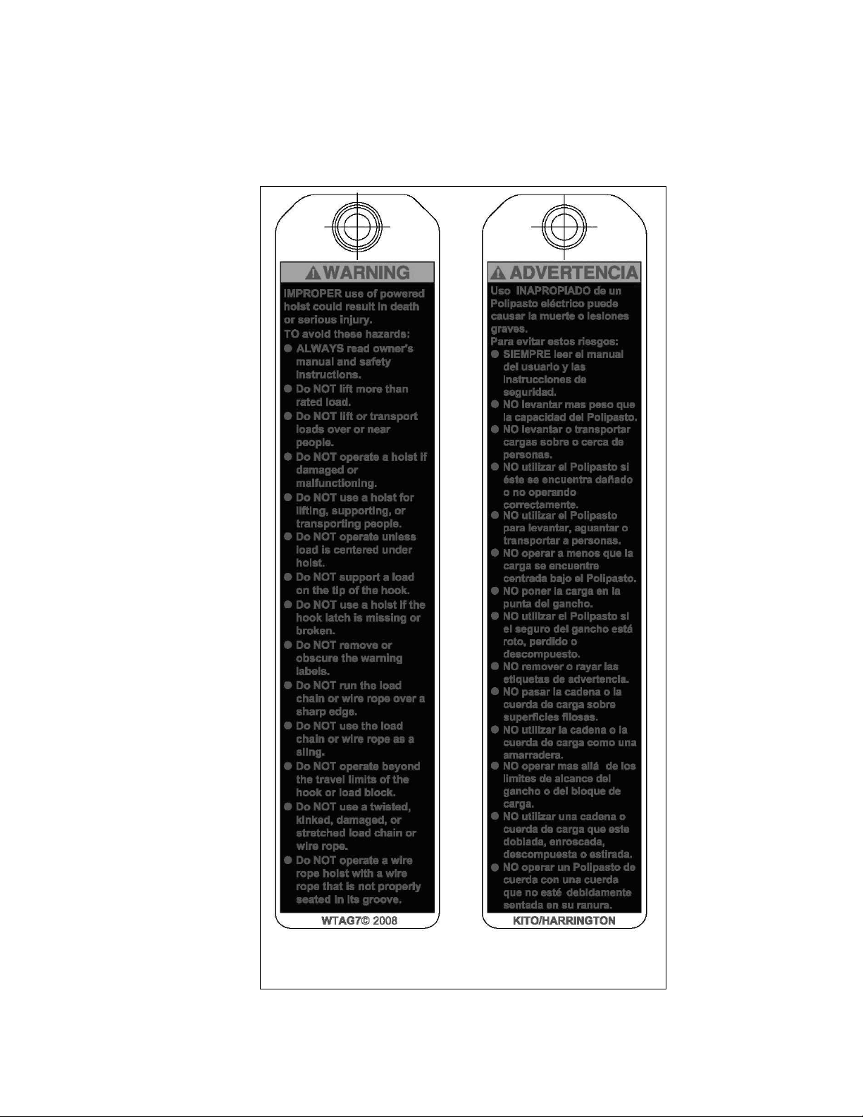
1.2 Warning Tag and Labels
The warning tag illustrated below in Figure 1-1 is supplied with each RHN hoist and trolley hoist shipped from
the factory. If the tag is not attached to the pendant cord for your hoist/trolley, order a tag from your dealer and
install it. Read and obey all warnings attached to this Trolley Hoist. Tag is not shown actual size.
front back
Figure 1-1 Warning Tag Attached to Trolley Hoist
7
2.0 Technical Informat ion
2.1 Specifications
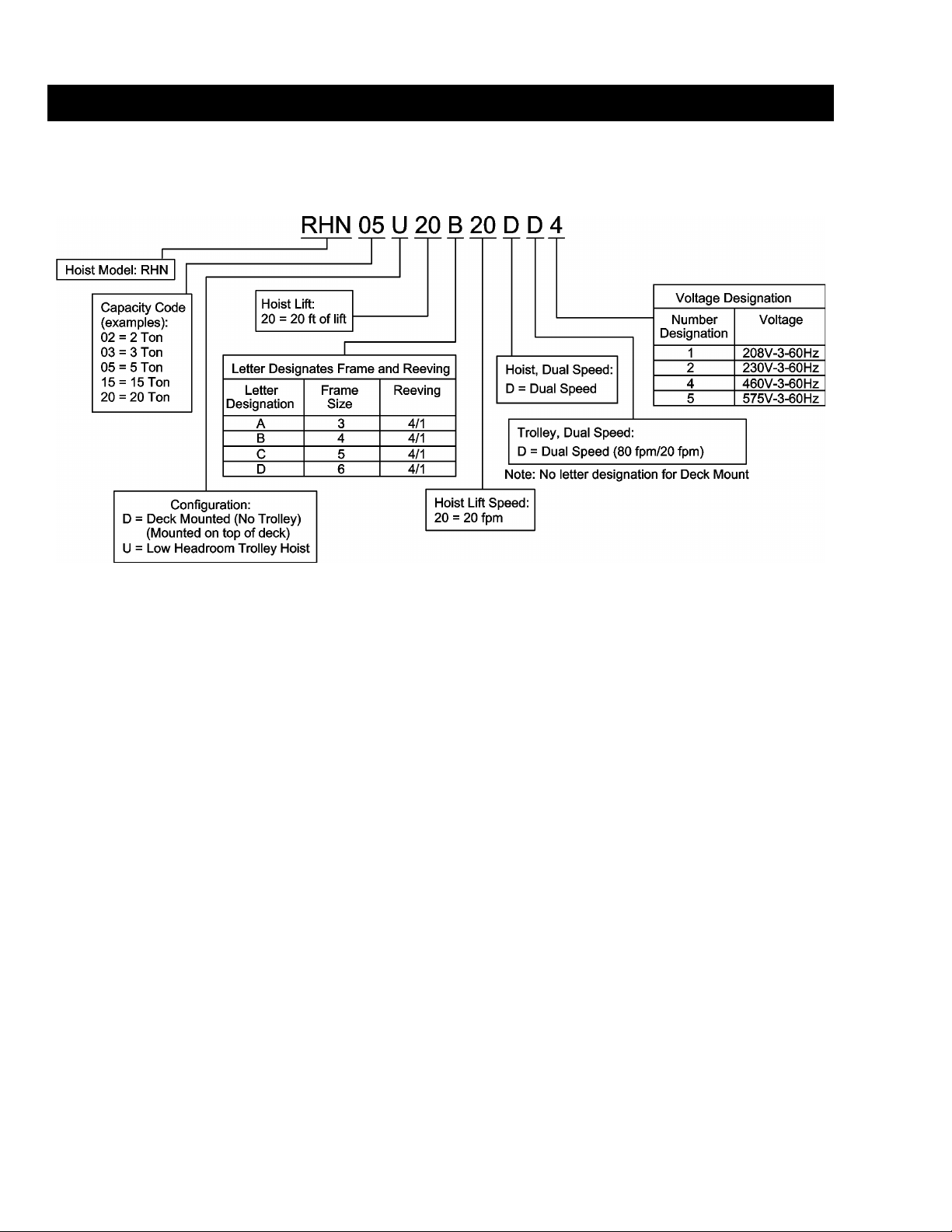
2.1.1 Product Code:
2.1.2 Operating Conditions and Environment
Temperature Range: +14° to +104°F (-10° t o +40°C)
Humidity: 80% or less
Electrical Enclosure Rating: IP55
Brake Enclosure Rating: IP66
Supply Voltage: 208V or 230V or 460V or 575V-3ph-60Hz
Control Voltage: 110V-1ph-60Hz
Noise Rating: less than 85 dba at full speed (A scale: measured 1 meter
away from electric wire rope hoist)
8

Table 2-1 Deck Mounted Hoist Specifications
Capacity
(Ton)
2
3
5
7 ½
10
15
20
*See Section 2.1.1 for place holder designation
Product Code*
RHN02D-20A-20D- 20
RHN02D-33A-20D- 33 375
RHN03D-20A-20D- 20
RHN03D-33A-20D- 33 375
RHN05D-20B-20D- 20
RHN05D-33B-20D- 33 485
RHN08D-20C-20D- 20
RHN08D-33C-20D- 33 1102
RHN10D-20C-20D- 20
RHN10D-33C-20D- 33 1102
RHN15D-20D-16D- 20
RHN15D-33D-16D- 33 2436
RHN20D-20D-16D- 20
RHN20D-33D-16D- 33 2436
Lift
(ft.)
Dual Speed Hoist Lifting Motor
Reeving
(Parts/
reeving)
Rope
Dia.
(mm)
Lifting
Speed
(ft/min)
Output
(Hp)
Hi/Low
4/1 7 20/3.5 5.8/0.9 17.0/8.4 8.3/4.0 6.6/3.2
4/1 7 20/3.5 5.8/0.9 17.0/8.4 8.3/4.0 6.6/3.2
4/1 9 20/3.5 7.2/1.2 22.0/11.0 10.0/5.4 8.2/4.3
4/1 12.5 20/3.5 14.8/2.1 42.0/21.0 20.0/10.0 16.0/8.0
4/1 12.5 20/3.5 14.8/2.1 42.0/21.0 20.0/10.0 16.0/8.0
4/1 20 16/2.5 24.1/4.0 67.0/27.0 32.0/13.0 25.6/10.4
4/1 20 16/2.5 24.1/4.0 67.0/27.0 32.0/13.0 25.6/10.4
3 Phase, 60 Hz
Current Draw
(amps) - Hi/Low
208&230V 460V 575V
Net
Weight
(lbs)
353
353
452
1025
1025
2271
2271
9

Table 2-3 Ultra-Low Headroom Trolley Hoists Trolley Specifications
Standard
Flange Range
RHN02U-20A-20DD-
RHN02U-33A-20DD-
RHN03U-20A-20DD-
RHN03U-33A-20DD-
RHN05U-20B-20DD-
RHN05U-33B-20DD-
RHN08U-20C-20DD-
RHN08U-33C-20DD-
RHN10U-20C-20DD-
RHN10U-33C-20DD-
RHN15U-28D-12DD-
RHN15U-46D-12DD-
Capacity
(Ton)
7 ½
10
15
Table 2-2 Ultra-Low Headroom Trolley Hoists Hoist Specifications
Reeving
Product Code*
2
3
5
RHN02U-20A-20DD- 20
RHN02U-33A-20DD- 33 650
RHN03U-20A-20DD- 20
RHN03U-33A-20DD- 33 650
RHN05U-20B-20DD- 20
RHN05U-33B-20DD- 33 831
RHN08U-20C-20DD- 20
RHN08U-33C-20DD- 33 1872
RHN10U-20C-20DD- 20
RHN10U-33C-20DD- 33 1872
RHN15U-28C-12DD- 28
RHN15U-46C-12DD- 46 3439
*See Section 2.1.1 for place holder designation.
Capacity
(Tons)
Lift
(Parts/
(ft.)
reeving)
Product Code
Dual Speed Hoist Lifting Motor
Rope
Dia.
(mm)
Lifting
Speed
(ft/min)
Output
(Hp)
Hi/Low
4/1 7 20/3.5 5.8/0.9 17.0/8.4 8.3/4.0 6.6/3.2
4/1 7 20/3.5 5.8/0.9 17.0/8.4 8.3/4.0 6.6/3.2
4/1 9 20/3.5 7.2/1.2 22.0/11.0 10.0/5.4 8.2/4.3
4/1 12.5 20/3.5 14.8/2.1 42.0/21.0 20.0/10.0 16.0/8.0
4/1 12.5 20/3.5 14.8/2.1 42.0/21.0 20.0/10.0 16.0/8.0
4/1 14 12/2.0 14.8/2.1 42.0/21.0 20.0/10.0 16.0/8.0
B*
(in)
Output
(Hp)
Hi/Low
208V 230V 460V 575V
3 Phase, 60 Hz
Current Draw
(amps) - Hi/Low
208&230V 460V 575V
Dual Speed Traversing Motor
80 and 20 ft/min
Current Draw
(amps) - Hi/Low
Net
Weight
(lbs)
617
617
767
1766
1766
3086
2
3
5
7 ½
10
15
*Optional wider flange ranges available up to 19.7 inches. Consult factory.
3.25-12 0.59/0.15 3.0/2.3 2.6/2.0 1.3/1.0 1.0/0.8
3.25-12 0.59/0.15 3.0/2.3 2.6/2.0 1.3/1.0 1.0/0.8
3.63-12 0.59/0.15 3.0/2.3 2.6/2.0 1.3/1.0 1.0/0.8
4.63-12 0.89/0.21 3.7/2.8 3.2/2.4 1.6/1.2 1.3/1.0
4.63-12 0.89/0.21 3.7/2.8 3.2/2.4 1.6/1.2 1.3/1.0
8.75-12 2.01/0.48 6.9/3.2 6.0/2.8 3.0/1.4 2.4/1.1
10
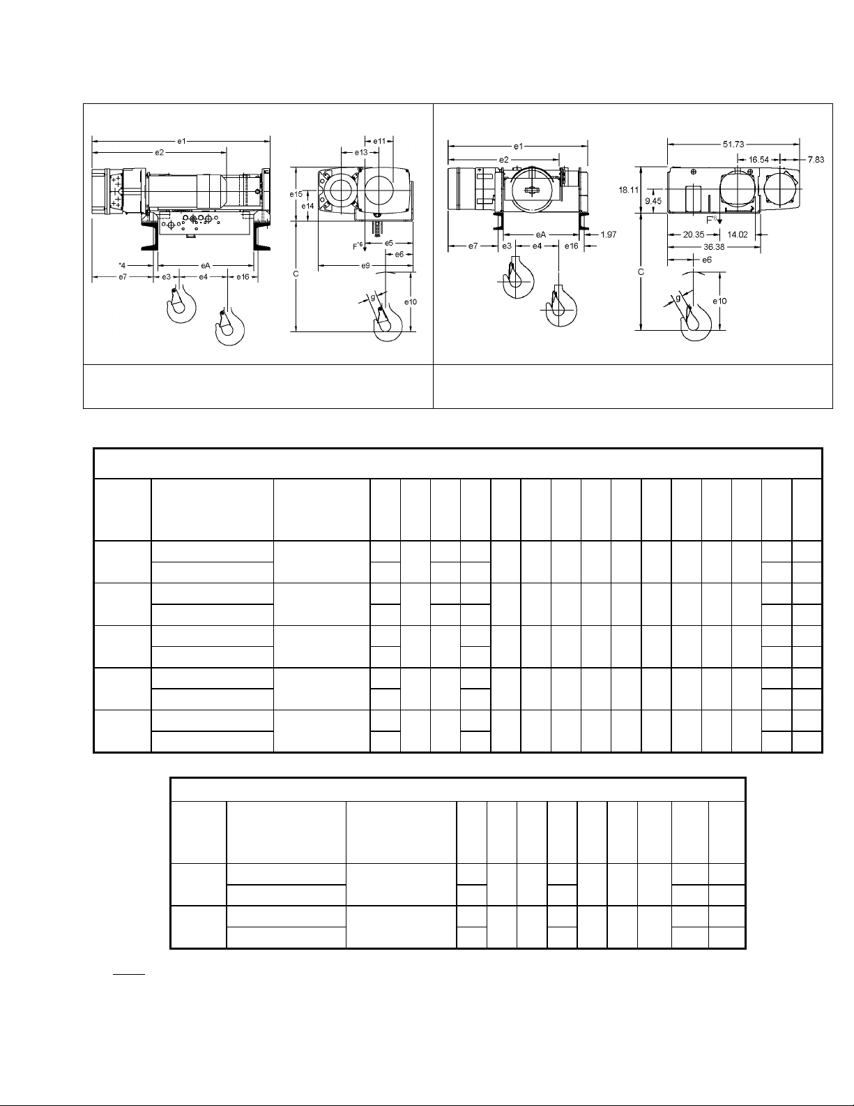
2.2 Dimensions
Table 2-4 Deck Mounted Hoist Dimensions (2-10 ton)**
Figure 2-1 2-10 ton Deck Mounted Hoist
Dimensions (See T able 2-4)
Capacity
(Tons)
2
3
5
7 ½
10
Product Code*
RHN02D-20A-20D-
RHN02D-33A-20D- 52.5
RHN03D-20A-20D-
RHN03D-33A-20D- 52.5
RHN05D-20B-20D-
RHN05D-33B-20D- 52.9
RHN08D-20C-20D-
RHN08D-33C-20D- 60.4
RHN10D-20C-20D-
RHN10D-33C-20D- 60.4
Min. Headroom
C
(in)
22.6
22.6
25.6
32.5
32.5
Table 2-5 Deck Mounted Hoist Dimensions (15 & 20 ton)**
e1
(in)
40.9
40.9
41.3
48.0
48.0
Figure 2-2 15-20 ton Deck Mounted Hoist
Dimensions (See T able 2-5)
e2
e3
e4
e5
e6
e7
e9
e10
e11
e13
e14
e15
(in)
(in)
(in)
(in)
(in)
(in)
(in)
(in)
(in)
(in)
(in)
(in)
6.3 4.6
29.6
6.2 7.6 22.1 33.8
6.3 4.6
29.6
6.2 7.6 22.1 33.8
31.2 6.4
39.3 9.5
39.3 9.5
9.0 4.8 13.9 21.3 11.5 4.9 7.2 6.3 11.0
9.0 4.8 13.9 21.3 11.5 4.9 7.2 6.3 11.0
4.3
11.2 5.9 14.3 22.0 13.8 6.6 8.8 7.2 12.9
7.2 22.2 33.8
4.6
14.1 7.5 17.2 28.6 18.2 8.6 11.7 9.4 16.9
7.8 21.8 37.0
4.6
14.1 7.5 17.2 28.6 18.2 8.6 11.7 9.4 16.9
7.8 21.8 37.0
e16
eA
(in)
(in)
13.3 22.2
13.3 22.2
13.5 22.2
12.6 24.6
12.6 24.6
Capacity
(Tons)
15
20
Notes:
*See Section 2.1.1 for place holder designation
** See Table 2-10 and Table 2-11 for attachment point dimensions
Product Code*
RHN15D-20D-16D-
RHN15D-33D-16D- 66.6
RHN20D-20D-16D-
RHN20D-33D-16D- 66.6
Min. Headroom
C
(in)
37.0
37.0
e1
(in)
54.4
54.4
e2
e3
(in)
(in)
43.7 13.4
43.7 13.4
e4
e6
e7
e10
e16
eA
(in)
(in)
(in)
(in)
(in)
(in)
4.6
10.9 19.5 29.7
7.6 24.9 41.9
4.6
10.9 19.5 29.7
7.6 24.9 41.9
15.7 29.7
15.7 29.7
11

†
Table 2-6 Ultra-Low Headroom Trolley Hoist Dimensions
e1
e4
e10
d1
d2
d3
f1
f2
f3
f5
f6
u1
u2
u3
u4
Capacity
(Tons)
2
3
5
7 ½
10
15*
Product Code*1
RHN02U-20A-20DD- 40.3 4.6
RHN02U-33A-20DD- 51.9 7.6 10.7 41.6 34.1 9.0 17.4
RHN03U-20A-20DD- 40.3 4.6
RHN03U-33A-20DD- 51.9 7.6 10.7 41.6 34.1 9.0 17.4
RHN05U-20B-20DD- 41.2 4.3
RHN05U-33B-20DD- 54.6 7.2 8.1 8.1 10.9 47.3 40.0 15.8 17.0
RHN08D-20C-20DD- 47.2 4.6
RHN08U-33C-20DD- 59.6 7.8 15.0 46.1 37.0 12.6 16.6
RHN10U-20C-20DD- 47.2 4.6
RHN10U-33C-20DD- 59.6 7.8 15.0 46.1 37.0 12.6 16.6
RHN15U-28D-12DD- 65.6
RHN15U-46D-12DD- 79.7† 7.7 15.2 69.5
(in)
(in)
(in)
(in)
(in)
(in)
(in)
11.5 28.6 18.0 3.7 13.9 8.9 6.5 6.1
11.5 28.6 18.0 3.7 13.9 8.9 6.5 6.1
13.8 30.8 18.2 3.7 13.5 9.1
18.2 37.0 22.9 4.5 16.1 11.4 10.7 9.8
18.2 37.0 22.9 4.5 16.1 11.4 10.7 9.8
†
4.6
23.0 44.4 25.2 6.6 24.5 11.8
(in)
(in)
(in)
(in)
(in)
11.9 30.0 22.4 9.1
11.9 30.0 22.4 9.1
7.7 6.5 12.1 29.8 22.4 9.9
15.7 33.7 24.6 12.6
15.7 33.7 24.6 12.6
10.0 10.0
16.7 49.4
(in)
(in)
†
40.7 15.9
60.8 23.7 29.4
u5
(in)
(in)
5.1 5.9
5.1 5.9
5.6 5.6
6.7 6.7
6.7 6.7
8.7 8.7
Notes:
* Refer to Table 2-7 for motor dimensions m0, m1, and m2. Motor dimension m0 may extend past the counterweight depending on the
hoist model and flange width B.
*1 - See Section 2. 1. 1 for place holder designation
*3 - Refer to Table 2-8 for flange range dimension B (Trolleys are suitable for use on S or W shaped beams)
*4 - Refer to Table 2-8 for headroom dimension C
*5/*6 – Observe clearance dimensions
† - For the 15t trolley hoist model, this measurement is to the end of the trolley frame because it extends past the drum cover shown in the
figure.
u6
(in)
8.7
8.7
8.3
7.4
7.4
20.3
12

Dimensions
Capacity
(Tons)
m0
(in)
m1
(in)
m2
(in)
RHN02U-20A-20DD-
RHN02U-33A-20DD-
RHN03U-20A-20DD-
RHN03U-33A-20DD-
RHN05U-20B-20DD-
RHN05U-33B-20DD-
RHN08U-20C-20DD-
RHN08U-33C-20DD-
RHN10U-20C-20DD-
RHN10U-33C-20DD-
RHN15U-28D-12DD-
RHN15U-46D-12DD-
Table 2-8 Ultra-Low Headroom Trolley Hoist
Headroom Dimensions
Headroom, C
(in)
Table 2-7 Ultra-Low Headroom Trolley Motor
Product Code*
2
3
5
7 ½
10
15
*See Section 2.1.1 for place holder designation
Capacity
(Tons)
2
3
5
7 ½
10
Flange Range, B
(in)
3.25-4.69 22.0
6.69-12 17.6+(0.58*T)
3.625-4.69 26.2
6.69-12 27.5-(0.23*T)
4.625-6.69 33.1-(0.29*T)
6.69-12 33.4-(0.35*T)
20.6 7.4 1.3
20.6 7.4 1.3
20.6 7.4 1.3
22.4 9.5 0.8
22.4 9.5 0.8
26.5 10.1 1.3
Headroom, C*
(in)
for 6 inch
Flange
21.7 4.69-6.69 23.4-(0.29*T)
26.0 4.69-6.69 26.6-(0.10*T)
31.4
15 8.75-12 40.8-(0.31*T) 38.0**
*T in formulas is the exact beam flange width in inches.
**Headroom value for 9 inch flange.
13

2.3 Miscellaneous
Table 2-9 Hook Dimension*
Units = inch
Capacity
(Tons)
2
3
5
7 ½
10
15
20
*Refer to Section 5.6 for inspection dimensions and limits.
**Product codes represent deck/base mounted hoists (except RHN15U), but hook dimensi ons also apply to ultra-low
trolley hoists. See Section 2.1.1 for place holder designation
Product Code** a b c d e f g h
RHN02D-20A-20D-
RHN02D-33A-20D-
RHN03D-20A-20D-
RHN03D-33A-20D-
RHN05D-20B-20D-
RHN05D-33B-20D-
RHN08D-20C-20D-
RHN08D-33C-20D-
RHN10D-20C-20D-
RHN10D-33C-20D-
RHN15U-28D-12DD-
RHN15U-46D-12DD-
RHN15D-20D-16D-
RHN15D-33D-16D-
RHN20D-20D-16D-
RHN20D-33D-16D-
2.2 1.8 1.9 1.5 2.2 2.5 1.6 5.8
2.2 1.8 1.9 1.5 2.2 2.5 1.6 5.8
2.6 2.1 2.3 1.8 2.5 2.8 1.7 6.6
3.1 2.5 2.6 2.1 2.8 3.1 1.9 7.7
3.1 2.5 2.6 2.1 2.8 3.1 1.9 7.7
3.9 3.1 3.3 2.6 3.5 4.0 2.4 10.1
4.9 3.9 4.2 3.3 4.4 5.0 3.2 12.0
4.9 3.9 4.2 3.3 4.4 5.0 3.2 12.0
14
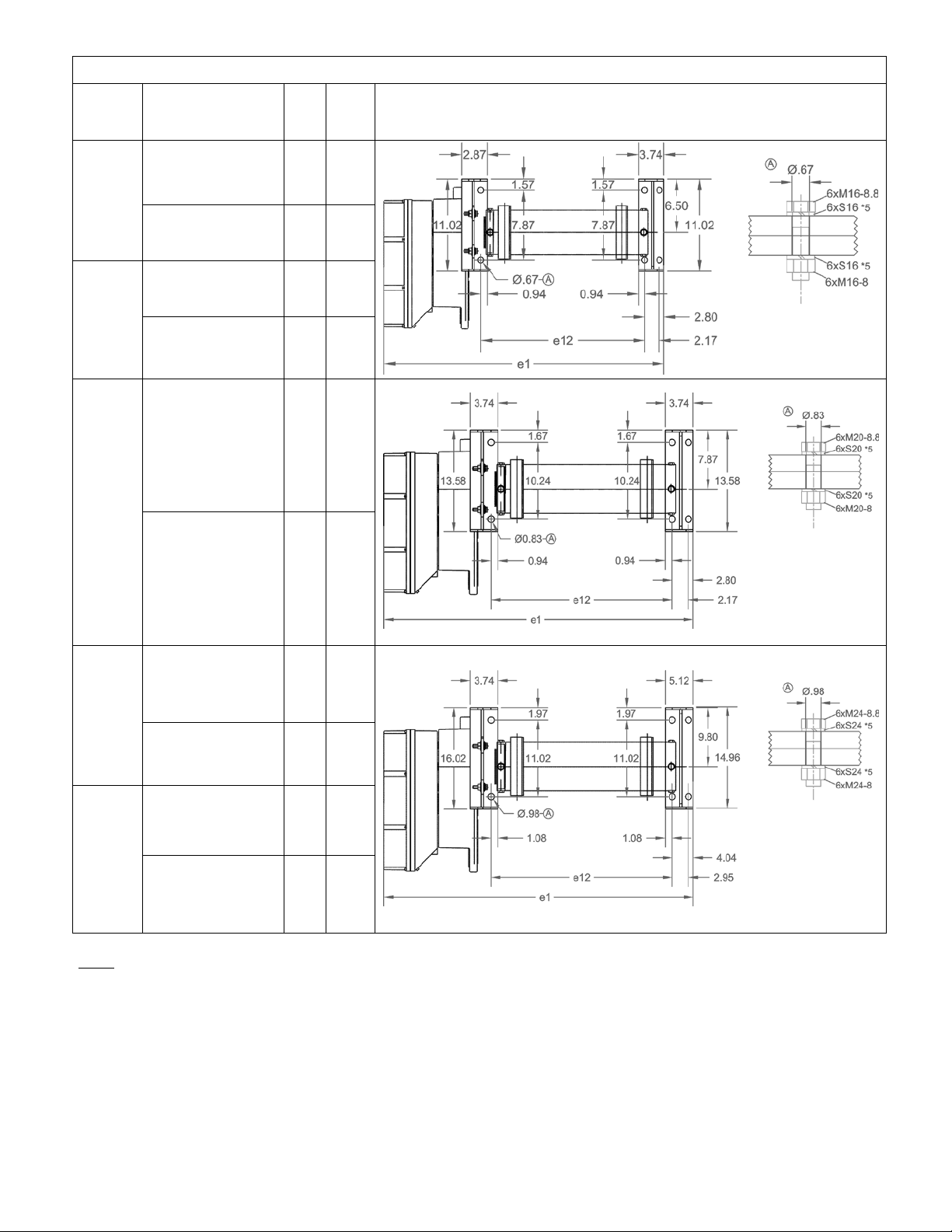
Table 2-10 Deck Mounted Hoist Attachment Point Dimensions (2-10 ton)
Capacity
(Tons)
2
3
5
e1
Product Code*
RHN02D-20A-20D- 40.9 24.2
RHN02D-33A-20D- 52.5 35.8
RHN03D-20A-20D- 40.9 24.2
RHN03D-33A-20D- 52.5 35.8
RHN05D-20B-20D- 41.3 24.2
(in)
e12
(in)
Deck/Base Mounted
RHN05D-33B-20D- 52.9 35.8
RHN08D-20C-20D- 48.0 26.8
7 1/2
RHN08D-33C-20D- 60.4 39.2
RHN10D-20C-20D- 48.0 26.8
10
RHN10D-33C-20D- 60.4 39.2
Notes:
*See Section 2.1.1 for place holder designation
*5 – Lock washer
15

Table 2-11 Deck Mounted Hoist Attachment Point Dimensions (15 & 20 ton)
Capacity
(Tons)
15
20
Notes:
*See Section 2.1.1 for place holder designation
*5 – Lock washer (Schnorr)
Product Code*
RHN15D-20D-16D- 54.4
RHN15D-33D-16D- 66.6 45.9
RHN20D-20D-16D- 54.4
RHN20D-33D-16D- 66.6 45.9
e1
(in)
e2
(in)
43.7
43.7
e12
(in)
33.7
33.7
Deck/Base Mounted
16

RHN02D-20A-20D-
1817
1902
654
1292
295
169
393
393
RHN02D-33A-20D-
1950
2149
582
1122
328
147
393
393
RHN03D-20A-20D-
2700
3043
1038
2067
472
270
629
629
RHN03D-33A-20D-
2906
3439
916
1795
524
235
629
629
RHN05D-20B-20D-
4171
4683
1618
3151
736
415
984
984
RHN05D-33B-20D-
4480
5272
1435
2744
814
362
984
984
RHN08D-20C-20D-
6989
5019
3625
5051
978
741
1475
1475
RHN08D-33C-20D-
7758
6054
3112
4278
1129
627
1475
1475
RHN10D-20C-20D-
9041
6692
4763
6735
1304
988
1967
1967
RHN10D-33C-20D-
10042
8072
4076
5703
1506
836
1967
1967
RHN15D-20D-16D-
9297
14086
5835
13988
1894
1684
3147
3147
RHN15D-33D-16D-
10384
16989
4931
12154
2227
1445
3147
3147
RHN20D-20D-16D-
12088
16707
7449
17186
2367
2105
3934
3934
RHN20D-33D-16D-
13494
20243
6316
14899
2784
1807
3934
3934
Figure 2-5 Deck Mounted Hoist, 2-10 Ton
Reaction Forces (See Table 2-12)
Figure 2-6 Deck Mounted Hoist, 15-20 Ton
Reaction Forces (See Table 2-12)
Table 2-12 Reaction Forces at Rated Load, Deck Mounted
Capacity
(Tons)
2
3
5
7 ½
10
15
20
See Section 2.1.1 for place holder designation
Product Code
F1
(lbs)
F2
(lbs)
F3
(lbs)
F4
(lbs)
Q1
(lbs)
Q2
(lbs)
Q3
(lbs)
Q4
(lbs)
Moment*,
M
T
(ft-lbs)
232*
372*
770*
1514*
2019*
**
**
*For 2-10t capacities, the customer’s substructu re must account for
the moment MT (torque) from the rope drum. Therefore it must be
torsion resistant and level, (max permissible offset, Y = .0787in.)
**For 15-20t capacities, the design structure accounts for the
moment, and the forces are diverted to the fixation points.
17

Trolley
Table 2-13 Wheel Pair Reaction Forces at Ra te d Lo ad ,
Ultra-Low Headroom Monorail
Capacity
(Tons)
2
3
5
7 1/2
10
15
20
Notes:
*See Section 2.1.1 for place holder designation
Product Code*
RHN02U-20A-20DD- 2985 2939
RHN02U-33A-20DD- 3632 2411
RHN03U-20A-20DD- 4292 4285
RHN03U-33A-20DD- 5253 3487
RHN05U-20B-20DD- 6629 7288
RHN05U-33B-20DD- 7167 6675
RHN08D-20C-20DD- 9102 12320
RHN08U-33C-20DD- 12011 9860
RHN10U-20C-20DD- 11783 16192
RHN10U-33C-20DD- 15641 12898
RHN15U-28D-12DD- 22045 17881
RHN15U-46D-12DD- 22226 18478
N/A
N/A
R1
(lbs)
R2
(lbs)
18
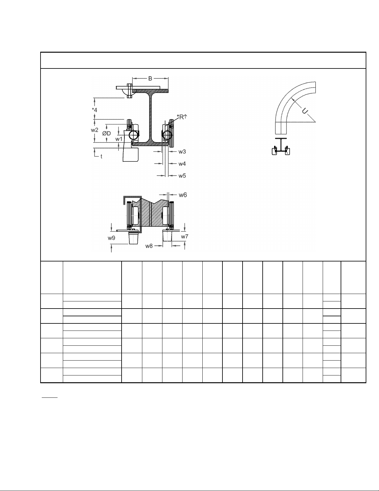
∅
2*
U
Maximum
Thickness
(in)
RHN02U-20A-20DD-
37.4*
RHN02U-33A-20DD-
56.8*
RHN03U-20A-20DD-
37.4*
RHN03U-33A-20DD-
56.8*
RHN05U-20B-20DD-
37.4*
RHN05U-33B-20DD-
56.8*
RHN08D-20C-20DD-
41.0*
RHN08U-33C-20DD-
61.7*
RHN10U-20C-20DD-
41.0*
RHN10U-33C-20DD-
61.7*
RHN15U-28D-12DD-
N/A
RHN15U-46D-12DD-
≤
Table 2-14 Trolley Wheel Dimensions
Wheel
Capacity
(Tons)
2
3
5
7 1/2
10
15
Product Code *5
Dia.
(in)
3.1 1.6 4.1 1.2 1.1
3.1 1.6 4.1 1.2 1.1
3.9 1.6 5.1 1.5 1.2
5.5 1.5 6.9 N/A 1.8
5.5 1.5 6.9 N/A 1.8
7.9 1.7 10.5 N/A 1.8
D
w1
(in)
Notes :
* Smaller bend radius upon request
** – ( ) with sloping flange
*R – See page 18 for reaction forces R1 and R2
*2 – only up to B
*4 – Observe clearance dimensions
*5 – See Section 2.1.1 for place holder designation
7.9 inches
w2
(in)
w3
(in)
(ft)
N/A
Flange
t
0.96
0.96
1.04
1.46
1.46
1.81
w4
(in)
w5
(in)
0.5
(0.6)**
0.5
(0.6)**
0.7
(0.9)**
0.9
(1.3)**
0.9
(1.3)**
0.9
(1.3)**
w6
(in)
0.2 2.1 2.0 2.5
0.2 2.1 2.0 2.5
0.2 2.1 2.0 2.5
0.5 2.1 2.5 2.5
0.5 2.1 2.5 2.5
0.5 2.1 2.5 2.5
w7
(in)
w8
(in)
w9
(in)
19

3.0 Pre-operational Pr ocedur es
3.1 General Information
3.1.1 When the RHN trolley hoist or deck mounted hoist is incorporated into lifting systems utilizing other
equipment, follow and complete all pre-operational procedures and instructions provided with the
equipment. Special wiring considerations must also be taken to complete the integration of the
RHN trolley hoist or deck mounted hoist into the system.
3.1.2 The RHN hoist is delivered pre-assembled on a pallet with a wooden frame. The frame is wrapped in
plastic for additional protection. (see Figure 3-1). During shipment and storage prior to installation, the
trolley hoist should be kept between –4° and +140°F (-20° and +60°C) and the relative humidity must
not exceed 80%. The standard packaging is not watertight and rainproof.
3.1.3 The RHN trolley hoist or deck mounted hoist is shipped pre-lubricated and the gear box(s) are filled
with the correct amount and type of oil. Follow the lubrication requirements in Section 6.1 after the
trolley hoist is placed into service.
3.2 Handling
3.2.1 Transportation – When moving the hoist or trolley hoist prior to installation, do not remove hoist from
crate. Always move hoist/trolley hoist utilizing a fork lift, pallet jack or hoist/crane system. Do NOT stack
or place anything on top of the trolley hoist or crate. Avoid swinging and unbalanced conditions.
3.2.2 Lift points – When a pallet/crate is not practical, use of RHN lifting location is acceptable. The RHN
deck mounted hoist is equipped with lifting lugs to facilitate lifting, while the RHN trolley hoist is
equipped with openings in the vertical tubes to accept hooks or slings (see
lifting do NOT support the deck mount hoist or trolley hoist any other way.
Figure 3-1 Packaged as delivered
Figures 3-2 and 3-3). While
20

Figure 3-2 Lift Point for Deck Mount
3.3 Mounting Location
3.3.1
adequate and capable of withstanding the forces generated by the hoist and the load. Therefore,
the substructure must be torsion resistant and level (See
mounting the RHN trolley hoist ensure that the trolley beam and its supporting structure are adequate to
support the trolley hoist and its load. (See Table 2-13). If necessary consult a professional that is
qualified to evaluate the adequacy of the suspension location and its supporting structure.
3.3.2 Ensure that there is adequate vertical and horizontal clearance along the entire range of the trolley
hoist’s motion.
3.3.3
Prior to mounting the RHN deck mounted hoist, ensure that the substructure is
See Section 6.8 for outdoor installation considerations.
Figure 3-3 Lift Point for Trolley Hoist
Table 2-12 for more details). Prior to
21

3.4 Assembly, Adjustments and Mounting
When installing the trolle y hoist on a beam, ALWAYS raise the hoist into position with the
trolley assembled together and securely attached to a pallet. Raise the trolley hoist with a forklift, lifting platform,
or other similar means. NEVER use slings to raise and install the trolley hoist onto the beam (see Figure 3-4).
Using a forklift or another suitable means, position the pallet so that the horizontal axis of the beam is parallel to
the horizontal axis of the hoist (see Figure 3-5)
Note: Unless specified when ordered, the RHN Trolley hoist is factory set to accommodate a 12 inch (306mm) beam
flange. If a smaller flange width is necessary, the driveshaft position and/or length may require a change as well (See
Table 3-1). If the supplied trolley drive shaft is too long for the desired flange, a short trolley drive shaft can be ordered, or
the existing shaft can be cut down to the appropriate length. Use caution and always wear eye protection when cutting
the trolley drive shaft with a powered saw or a manual saw. Deburr the cut end of shaft before reinstalling. The RHN is
equipped with the maximum number of counterweights necessary for the standard (advertised) flange range for each
capacity. If the flange range exceeds 12 inches (306mm), some counter weight may need to be removed to achieve
proper balance.
3.4.1 RHN Trolley Hoist Installation
1) Make sure the mounting location complies with Section 3.3.
2) Before attempting to install the trolley hoist, verify beam width and the “c” dimension (see Figure 3-6).
See Table 3-1 for dimensions respective values. If adjustment is not necessary, move onto section
Section 3.4.1 (step 8). If adjustment is necessary move onto step 3, below.
3) Determine the correct driveshaft length for your application.
a. If a shorter driveshaft length is required, it is necessary to replace or cut the existing driveshaft to the
appropriate length. (See Table 3-2)
b. If a longer driveshaft length is required, it is necessary to replace the existing driveshaft with one of
the appropriate length. (See Table 3-2)
4) Determine the correct Snap Ring Position on the driveshaft, for your application. (2 ton – 10 ton)
Each driveshaft has multiple Snap Ring positions shown as X3 and X4. These different positions allow
the Trolley Driveshaft to be inserted at two different depths within the motor housing. This gives the
drive shaft the ability to accommodate a range of beam flange widths before it necessary to change the
shaft length.(See Table 3-2)
5) Accessing the Drive Shaft for replacement, shortening and/or Snap Ring relocation.
a. Carefully remove the trolley motor by loosening and removing the 4 trolley motor mounting bolts. It
may be necessary to disconnect the trolley motor cable, if there is not enough slack to allow for the
motor to be safely supported, as work is being performed. With the bolts removed, the motor can
slide off of the drive shaft.
b. With the motor removed and safely placed out of the way, the driveshaft can pulled out of the trolley
assembly.
6) Adjust the trolley flange to fit beam width.
a. Working on the trolley motor side of the hoist, (the side closest to the large rectangular counter
weights), loosen the nuts (2) on the two threaded shafts (1) of the trolley hoist. DO NOT loosen the
nuts closest to the hoist. NEVER move the hoist side of the trolley. (See Figure 3-6 and Figure
3-11)
22

b. With the nuts (2) loosened enough to allow the trolley frame to move, slide the trolley motor side of
the hoist outward or inward to meet the desired flange width. Tighten nuts (2) with a torque wrench,
to 155 ft lbs (210 Nm). (See Figure 3-6 and Figure 3-11.)
7) Installing the Drive Shaft
a. 2Ton – 10Ton Trolley Hoist
Install Snap Rings (S) on to Driveshaft (D) in position X3 or X4 depending on flange width (B)
of the runway beam and length (L) of drive shaft (D). Slide Drive Shaft through drive pinions
and install trolley motor. (See Figures 3-8, and 3-9. Also see Tables 3-2 and 3-3.)
b. 15 Ton Trolley Hoist
Insert drive shaft (5) into the two drive pinions (6) from the counterweight side, then assemble
spacer tube (7) and adjusting ring (8). (See Figure 3-11).
Adjust drive shaft (5) so that on the hoist side of the shaft end projects between “min. 0in. (0mm)”
and “max. 4.72 in.(120mm)” beyond the drive pinion (6) and on the counterweight side the shaft end
projects between “min. 1.89 in. (48 mm)” and “max. 6.30in. (160 mm)” beyond the trolley frame (10).
(See Figure 3-11).
Lock adjusting ring (8) with the adjusting screw so that there is approximately "3 mm” space
between spacer tube (7) and the adjusting ring (8) when spacer tube (7) is against drive pinion (6).
After fitting travel drive, check drive shaft (5) for ease of movement. (See Figure 3-11).
8) Mounting the Trolley Hoist to the beam.
a. Install any additional devices, if any (power supply cords or pendants, for instance – see Section
3.5), onto the trolley hoist. If the trolley hoist is not secured to a pallet, place and secure it to one
making sure that the trolley hoist is completely stable.
b. Before attempting to install the trolley hoist, verify beam width and the “c” dimension (see Figure 3-
6). See Table 3-1 for dimensions respective values. Adjust flange width if necessary. (See Section
3.4.1 Step 6)
c. If the end of the runway beam is accessible, slide the trolley hoist onto the end of the runway
beam. Check clearance f/2 ( Figure 3-7 and Table 3-1). Adjust if necessary. (See Section
3.4.1 Step 6).
If the end of the runway beam is not accessible, the trolley flange width will nee d to be opened
up to allow the Trolley Hoist to fit around the beam. (See Section 3.4.1 Step 6).
23

Table 3-1 Trolley Clearances and Wheel Diameters
in
mm
in
mm
in
mm
in
mm
RHN02
RHN03
RHN05
4
100
B+2 5/8
B+67
1/16
1.5
5 3/4
147
RHN08
RHN10
RHN15
8
200
B+3 5/8
B+67
1/16
1.5
7 3/8
187
Figure 3-4 Lift Point for Deck Mount
Figure 3-6 Trolley Hoist Clearances 2 Ton – 10 Ton
Figure 3-5 Lift Point for Trolley Hoist
Figure 3-7 Trolley Hoist Clearances
Hoist
Wheel Diameter c f/2 y
3 1/8 80 B+2 5/8 B+67 1/16 1.5 5 3/8 137
5 1/2 140 B+2 5/8 B+67 1/16 1.5 6 3/8 162
24

Table 3-2 Drive Shaft Length and Positions for
Fig 3-8, 3-9 and 3-11
Drive Shaft
Shaft Length
“L” (mm)
Snap Ring
Position “S”
3.25-5.71 (82-145)
X3
5.75-7.68 (146-195)
X4
7.72-9.84 (196-250)
X3
9.88-12.05 (251-306)
X4
12.09-13.78 (307-350)
X3
13.82-15.71 (351-399)
X4
15.75-17.72 (400-450)
X3
17.76-19.69 (451-500)
X4
3.63-5.71 (92-145)
X3
5.75-7.68 (146-195)
X4
7.72-9.84 (196-250)
X3
9.88-12.05 (251-306)
X4
12.09-13.78 (307-350)
X3
13.82-15.71 (351-399)
X4
15.75-17.72 (400-450)
X3
17.76-19.69 (451-500)
X4
4.63-7.87 (117-200)
X3
7.91-12.20 (201-310)
X4
12.24-15.75 (311-400)
X3
15.79-19.69 (401-500)
X4
6.69-8.66 (170-220)
20.08 (510)
8.70-15.75 (221-400)
29.13 (740)
15.79-19.69 (401-500)
30.71 (780)
Figure 3-8
Figure 3-9
Hoist
Beam Flange Width
in. (mm)
15.35 (390)
RHN02
19.49 (495)
RHN03
23.43 (595)
27.36 (695)
15.35 (390)
19.49 (495)
RHN05
23.43 (595)
RHN08
RHN10
RHN15
27.36 (695)
19.88 (505)
27.95 (695)
See Figure 3-11
25

Table 3-3 L3 and L4 Dimensions from
Fig 3-8 and 3-9
Hoist
L3+/- 2 in. (mm)
L4+/-2 i n. (mm)
RHN02, RHN03,
RHN05
3.8 (96.4) 1.82 (46.4)
RHN08, RHN10 4.9 (124.6) 1.82 (46.4)
RHN15 See Figure 3-11
Figure 3-11 Trolley Hoist Clearances 15 Ton
26

3.5 Electrical Connection s
3.5.1
3.5.2
lifting or traversing motors. Use of such devices may cause the motor brake and other electrical
components to malfunction. For variable frequency drives contact Harrington for more information.
3.5.3
de-energized (disconnected). Lock out and tag out in accordance with ANSI Z244.1 “Personnel
Protection -Lockout/Tagout of Energy Sources”.
3.5.4 Installing Power Supply Cord
1) Refer to Figure 3-12, Figure 3-13 and the wiring diagram provided with the Hoist.
2) Remove Control Cover.
3) Loosen the cable fitting located on the lower side of the electrical enclosure and insert the Power
Supply Cable. Pull through enough cable to reach the power supply terminal and securely tighten
the cable fitting.
4) Connect the 3 phase power leads (L1, L2 and L3) and the ground lead of the Power Supply Cable
to the power supply terminal. Make sure the terminals are securely tightened and each lead is
completely isolated.
5) Replace the Control Cover. Be careful to not damage the seal or sealing surfaces and make sure to
securely tighten all fasteners or latches.
Ensure that the voltage of the electric power supply is proper for the trolley hoist.
Do NOT apply electronic soft-start control or voltage varying controls to the RHN
Before proceeding, ensure that the electrical supply for the hoist or trolley has been
Figure 3-12
Figure 3-13
27

3.6 Pendant Installation
1) Refer to Figure 3-14, Figure 3-15 and the wiring diagram and the interconnection diagram provided with
the Hoist.
2) Remove Control Cover.
3) Loosen the cable fitting located on the lower side of the electrical enclosure and insert the Pendant
Cable. Pull through enough cable to reach the terminals then securely tighten the cable fitting.
4) Attach a strain relief cable or chain between the pendant and hoist. The cable should attach to the small
plate located at the bottom of the electrical enclosure under the gear box.
5) Access to terminal strip: The terminal strip is mounted on DIN rail, located on the lower portion of the
control box.
6) Connect the individual pendant leads to the correct terminals as shown on the interconnection diagram.
Make sure the terminals are securely tightened and each lead is completely isolated.
7) Reinstall the Control Cover. Be careful to not to pinch any wires wire closing and tightening down the
Control Cover.
Figure 3-14
3.6.1 Connection to Electrical Power Source - The 3 power leads of the Power Supply Cable (normally red,
white, and black wires) should be connected to an electric power disconnect switch or circuit breaker.
This connection should be made so that the hoist is phased properly. Refer to Section 3.9.4 for
instructions on how to check for correct power supply phase connection.
3.6.2 Fuse/Breaker Capacity - The trolley and hoist's power supply should be equipped with overcurrent
protection such as fuses, which should be selected for 110% to 120% of total listed full load amperage,
and should be dual element time-delay fuses. For the total full load amperage draw, add the amperage
draws shown on the motor nameplates of ALL lifting and traversing motors.
3.6.3
shock hazard when touching any part of the hoist or trolley. In the Power Supply Cable the ground wire
will be either Green with Yellow stripe or solid Green. It should always be connected to a suitable
ground connection. Do not paint the trolley wheel running surfaces of the beam as this can affect
grounding.
Grounding - An improper or insufficient ground connection creates an electrical
Figure 3-15
28

3.7 RPU Load Monitor Device
The RHN hoist is equipped with the RPU Load Monitor Device. The RPU version (SLE21 or SLE22) is located
on the front cover of the RPU unit. The main function of this device is to evaluate the load conditions of the hoist
(overload protection, temperature monitoring of the hoist and trolley motors, and displaying the operating hours of
the hoist.
3.7.1 Monitoring of Load Conditions – After powering up the hoist, the RPU will run through an internal test
cycle, for approximately 4 seconds. The test will be finalized when the user initially operates the hoist in
the up or down direction. At this time the “err” light will illuminate temporarely as well as the LEDs II and
III. If the internal test cycle was completed successfully without resulting in error, the hoist will function.
3.7.2 Temperature Monitoring – The hoist and trolley motors are equipped with PTC thermistors that are
directly linked to the RPU. If an excessive motor temperature condition has developed, the RPU will not
allow the load to be lifted or lowered until the excessive temperature condition is no longer present. The
LED display on the RPU will display and “err”. See Table 7-2.
3.7.3 Count/Hour Meter – See section 6.1 for Count/Hour meter details.
3.7.4 Load Testing RHN – The RPU Load Monitoring device is designed to sense an overload of the hoist and
cut-off power when subjected to a lifting load of 110% of the rated RHN capacity. Due to this load
monitoring feature, a Crane Test function is used when conducting a load test of 125% of the rated
capacity. The crane test function temporarily changes the overload cut-off from 110% rated capacity to
137.5% rated capacity. This temporary load test override for both RPU versions (SLE21 or SLE22) is
accomplished by following the applicable instructions below:
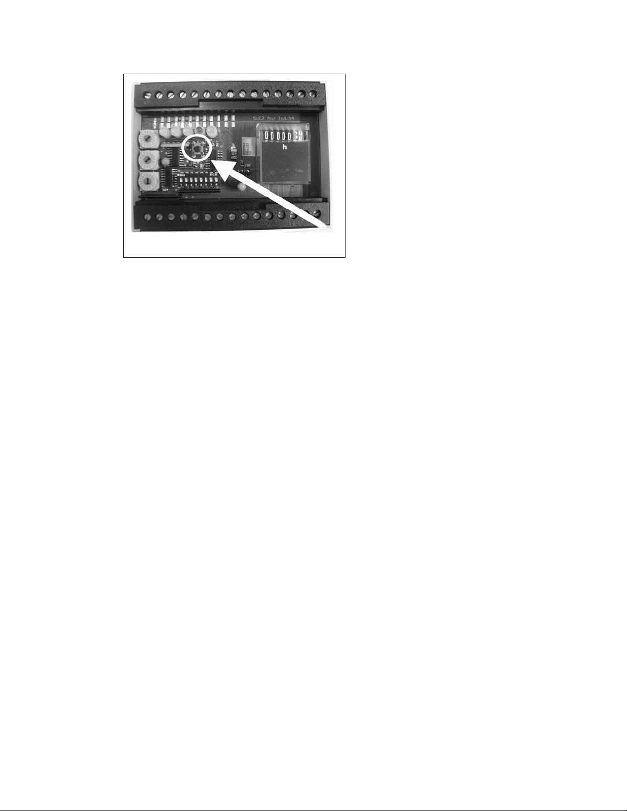
For Model SLE21:
1. Remove RPU cover.
2. Press the S5 button, hold for more than 3 seconds, and release. (The S5 button is located directly
below the red “err” LED). Figure 3-16.
3. Notice the “err” LED is flashing. This will continue to flash for 30 minutes. After 30 minutes, the
RPU reboots and the overload cut-off returns to 110% of the rated capacity.
For Model SLE22:
1. Loosen the screw on the RPU cover and remove the cover.
2. Execute the following steps in less than 12 seconds:
a. Press the S5 button for more than 3 seconds. (The S5 button is located directly below the red
“err” LED). See Figure 3-16.
b. Release the S5 button for 1 second.
c. Press the S5 button for more than 3 seconds.
3. If an error occurs in the sequence of step 2, the “err” LED flashes 3 times. After this error signal, the
crane test function can be activated again by following the sequence in step 2.
4. If the sequence in step 2 is followed correctly, then the “err” LED will flash for 30 minutes. After 30
minutes, the RPU reboots and the overload cut-off returns to 110% of the rated capacity.
5. To deactivate the crane test, either press the S5 button until the red LED no longer flashes or reboot
the device.
29
↑↑
↑↑
↑↑
↑
↑
↑
↑
↑
↑
↑
↑
↑
↑
↓
↓
Figure 3-16
3.8 H oist Limit S witches and Adjustment
The RHN wire rope hoist is equipped with a geared limit switch in the hoist control panel box. The limit switch is
equipped with four switches, all of which are utilized for standard hoist functions. The four limit switch positions are
as follows: S1 (Upper Safety Limit), S2 (Lower Limit), S3 (Upper Limit), and S4 (Speed Transition Limit).
The wire rope hoist is also equipped with a BLS (Block Limit Switch) as a standard feature.
3.8.1 Description and order of the limit switch function, including BLS as hook travels in the UP direction – See
Figure 3-17.
(Speed Transiti on Geared Limit ): As the hook travels in the up direction, the first switch
S4
position to activate will be S4
deactivated when the S4
switch position S3
(Upper Geared Limit): When the S3↑switch position is activated, hook travel is disabled in the up
S3
(Upper Limit).
. If the hoist is being operated in the up direction, high speed will be
switch is activated. The hoist will then remain in low speed until reaching the
direction. The hoist can still be operated in down direction.
BLS
(Block Ope rate d Upper Limit S witch): See also Figure 3-19.
In addition to the geared limit switch, there is also a block operated upper limit switch (BLS
on the hoist. The BLS
the cable that holds the switch in the closed position. The BLS
Geared Limit) switch position activates first and the BLS
switch opens when the hook block lifts a weight and releases the tension from
is adjusted so that the S3↑(Upper
second as a “back-up” safety.
(Upper Safety Geared Limit): In the event of a major malfunction where the upper limit switch
S1
(S3
) and the block operated upper limit switch (BLS↑) are overrun, the S1↑switch position is
activated and disables all directional movement and control. The only way to operate the hoist after the
switch has been activated is to eliminate the source of the problem and bridge (jumper) terminals
S1
110 to 116 on the terminal strip located at the bottom of the hoist control panel box. WARNING: If the
S1 Geared Limit Switch pos ition has been ac tivated, a major m alfunctio n has occurr ed.
Therefore, the equipment should be ins pected by a quali fied indi vidual befor e att empting to
resume hoist operati on.
3.8.2 Description and order of the limit switch function as the hook travels in the DOWN direction – See
Figure 3-18.
(Speed Transition Ge ared Li mit): When the hook is located at the S3 (Upper Geared Limit)
S4
position, and moving in the down direction, the hoist will remain at low speed until the hook is below the
) installed
30