

Page 1
EFFECTIVE: May 20, 2008
Owner’s Manual
MOTORIZED
TROLLEY
MR SERIES
1 Ton through 20 Ton Capacity
Code, Lot and Serial Number
WARNING
This equipment should not be installed, operated or maintained
by any person who has not read and understood all the
contents of this manual. Failure to read and comply with the
contents of this manual can result in serious bodily injury or
death, and/or property damage.
Page 2

Table of Contents
Section Page Number
1.0 Important Information and Warnings………………………………………………………………………. 4
1.1 Terms and Summary
1.2 Warning Tags and Labels
2.0 Technical Information ………………………………………………………………………………………. 8
2.1 Specifications
2.2 Dimensions
3.0 Pre-operational Procedures………………………………………………………………………………...10
3.1 Assembly and Adjustment
3.2 Mounting Location
3.3 Installation of Trolley onto Beam
3.4 Electrical Connections
3.5 Pre-operational Checks and Trial Operation
4.0 Operation…………………………………………………………………………………………………… 25
4.1 Introduction
4.2 Shall’s and Shall Not’s for Operation
4.3 Trolley and Hoist Controls
5.0 Inspection…………………………………………………………………………………………………… 28
5.1 General
5.2 Inspection Classification
5.3 Frequent Inspection
5.4 Periodic Inspection
5.5 Occasionally Used Trolleys
5.6 Inspection Records
5.7 Inspection Methods and Criteria
2
Page 3

Section Page Number
6.0 Maintenance & Handling…………………………………………………………………………………... 34
6.1 Lubrication
6.2 Brake
6.3 Storage
6.4 Outdoor Installation
7.0 Troubleshooting……………………………………………………………………………………………. 35
8.0 Warranty……………………………………………………………………………………………………. 36
9.0 Parts List…………………………………………………………………………………………………….37
9.1 Electrical Parts
9.2 Pendant Parts
9.3 Power Supply Parts
9.4 Side Plate and Suspension Parts
9.5 Motor Parts
3
Page 4

1.0 Important Information and Warnings
1.1 Terms and Summary
This manual provides important information for personn el involved with the insta llation, operation an d maintenance
of this product. Although you may be familiar with this or similar equipment, it is strongly recommended that you read
this manual before installing, operating or maintaining th e product.
Danger, Warning, Caution and Notice - Through out this manual there are steps and procedures that can pre sent
hazardous situations. The following signal words are used to identify the degree or level of hazard seriousness.
DANGER
Danger indicates an imminently hazardou s situation which, if not avo ided, will result in death or
serious injury, and property damage.
WARNING
CAUTION
NOTICE
These general instructions deal with the no rmal installatio n, operation, and maint enance situation s encountered with
the equipment described herein. The inst ructions sh ould not be interp reted to anticipate eve ry possible co ntingency
or to anticipate the final system, crane, or configuratio n that uses this e quipment. For syst ems using the equipment
covered by this manual, the supplier and o wner of the syst em are responsible for the system’s compliance with all
applicable industry standard s, and with all app licable federal, state and local regulations/codes.
This manual includes instructions an d parts information for a v ariety of trolley an d hoist types. Therefore, all
instructions and parts information may n ot apply to any one type or size of specific trol ley or hoist. Disrega rd those
portions of the instructions that do not apply.
Warning indicates an imminently hazardous situatio n which, if not avoided, could result in death or
serious injury, and property damage.
Caution indicates a potentially hazardous situation whi ch, if not avoided, may re sult minor or
moderate injury or property damage.
Notice is used to notify people of installation, operation, or maintenanc e information whi ch is
important but not directly hazard-related.
CAUTION
Record your trolley’s Code, Lot and Serial Number on the front cover of this manual for identification and future
reference to avoid referring to the wrong manual for informatio n or instructions o n installation, ope ration, inspection,
maintenance, or parts.
Use only Harrington authorized replacement pa rts in the servi ce and maintena nce of this trolley.
4
Page 5

WARNING
Equipment described herein is not designed for and MUST NOT
or for lifting or supporting loads over peop le.
Equipment described herein should not be used i n conjunction with other equi pment unless necessary and/ or
required safety devices applicable to the system, crane, or appli cation are instal led by the syste m designe r, system
manufacturer, crane manufacturer, installer, or user.
Modifications to upgrade, rerate, or otherwise alter this equipm ent shall be auth orized only by the ori ginal equipment
manufacturer.
Equipment described herein may be used in the desi gn and manufactu re of cranes or mon orails. Additional
equipment or devices may be required for the crane and monorail to comply with applicabl e crane design and safety
standards. The crane designer, crane manufactu rer, or user is respo nsible to furnish the se additional items for
compliance. Refer to ANSI/ASME B30.17, “Safety Standard for Top-Running Single Girder Cranes”; ANSI/ASME
B30.2 “Safety Standard for Top-Running Double-Girder Cranes”; and ANSI/ASME B30.11 “Safety Standard for
Underhung Cranes and Monorails”.
If a below-the-hook lifting device or sling is used with a hoist, refer to ANSI/ASME B30.9, “Safety Standard for Slings”
or ANSI/ASME B30.20, “Safety Standard for Below-the-Hook Lifting Devices”.
be used for lifting, supporting, or transporting people,
Hoists, trolleys and cranes, used to handle hot molten material may re quire additional equipment or devi ces. Refer to
ANSI Z241.2, “Safety Requirements for Melting and P ouring of Metals i n the Metalcasting In dustry”.
Electrical equipment described herein is design ed and built in co mpliance with Harri ngton's interpretation of
ANSI/NFPA 70, “National Electrical Code”. The system designer, system manufacturer, crane designer, crane
manufacturer, installer, or user is resp onsible to a ssure that the i nstallation a nd associated wi ring of these electrical
components is in compliance with ANSI/NFPA 70, and all applicable Federal, State and Local Codes.
Failure to read and comply with any one of the limitation s noted herein can result in seriou s bodily injury or death,
and/or property damage.
5
Page 6

DANGER
HAZARDOUS VOLTAGES ARE PRESENT IN THE CONTROL BOX, OTHER ELECTRICAL COMPONENTS,
AND CONNECTIONS BETWEEN THESE COMPONENTS.
Before performing ANY mechanical or electrical mainten ance on the equipme nt, de-energize (disconn ect) the main
switch supplying power to the equipment; and lock and t ag the main swit ch in the de-e nergized positio n. Refer to
ANSI Z244.1, “Personnel Protection – Lockout/Tagout of Energy Sources”.
Only trained and competent personnel should i nspect and repair th is equipment.
NOTICE
It is the responsibility of the owner/user to install, inspe ct, test, maintain, and op erate a trolley or hoi st in accordance
with ANSI/ASME B30.16, “Safety Standard for Overhead Hoists”, OSHA Regulations and ANSI/NFPA 70, "National
Electric Code". If the trolley is installed as part of a total li fting system, such as an overh ead crane or monora il, it is
also the responsibility of the owner/user to comply with the applicable ANSI/ASME B30 volume that addresses that
type of equipment.
It is the responsibility of the owner/user to have all personne l that will install, in spect, test, maint ain, and operate a
hoist read the contents of this manual and appli cable portions of ANSI/ ASME B30.16, “Safety Standa rd for Overhead
Hoists”, OSHA Regulations and ANSI/NFPA 70, “Natio nal Electric Co de”. If the trolley is inst alled as pa rt of a total
lifting system, such as an overhead crane, the applicable ANSI/ASME B30 volume that addresses that type of
equipment must also be read by all perso nnel.
If the trolley owner/user requires additional information, or if any informatio n in the manual is not clear, contact
Harrington or the distributor of the trolley. Do not inst all, inspect, test, maintain, or operate this trolley unless this
information is fully understood.
A regular schedule of inspection of the trolley in accordance with the requirements of ANSI/ASME B30.16 should be
established and records maintained.
6
Page 7
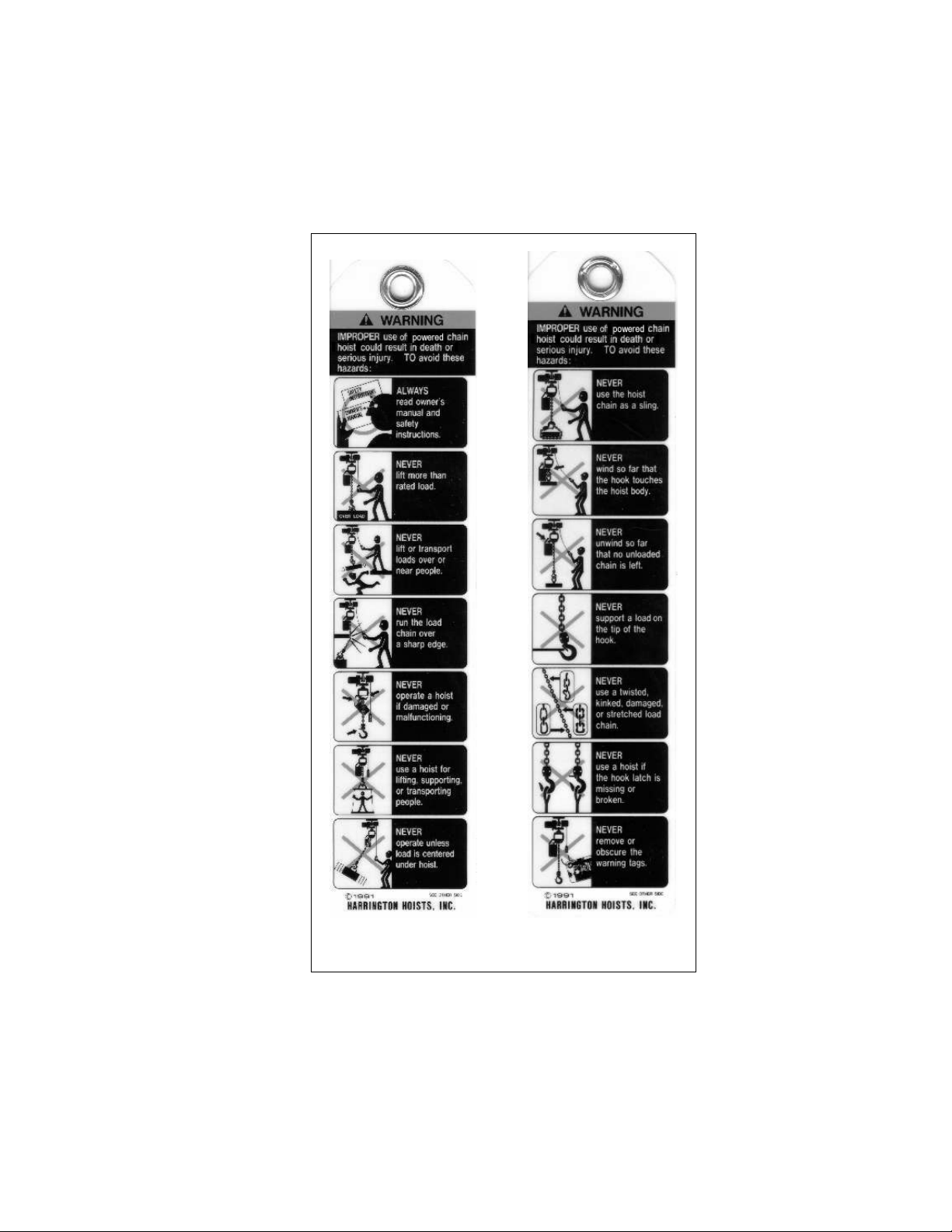
1.2 Warning Tag and Labels
The warning tag illustrated below in Figure 1-1 is supplie d with each trolley ship ped from the factory. If the tag i s not
attached to the pendant cord for your hoist/trolley, order a tag from your dealer and install it. Read and obey all warnings
attached to this trolley. Tag is not shown actual size.
front back
Figure 1-1 Warning Tag Attached to Trolley
7
Page 8
2.0 Technical Information
2.1 Specifications
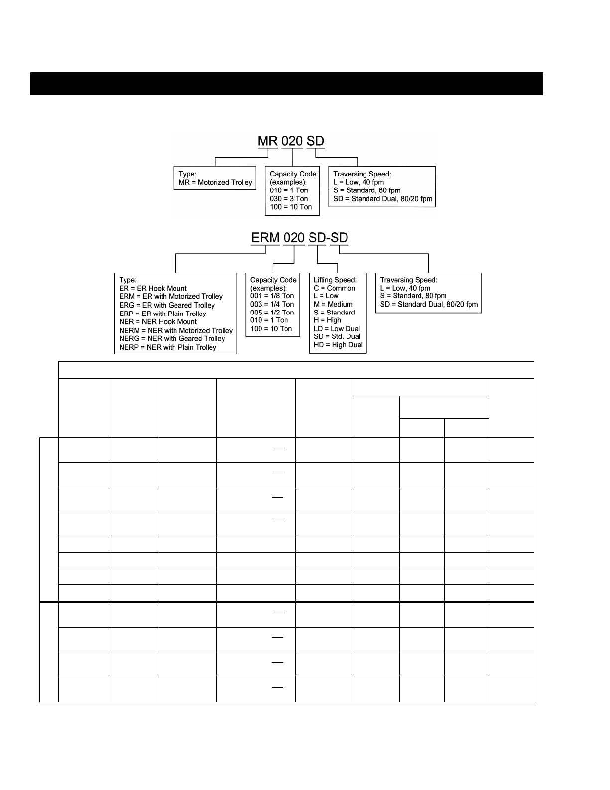
2.1.1 Product Code for MR Trolley Alone:
SINGLE SPEED
DUAL SPEED
2.1.2 Product Code for MR Trolley with ER Series Electric Hoist:
Table 2-1 Trolley Specifications
Standard
Capacity
(Ton)
1 MR010L/S 2.28 to 5.00
2 MR020L/S 3.23 to 6.02
3 MR030L/S 3.23 to 6.02
5 MR050L/S 3.94 to 7.01
8 MR080L 5.91 to 8.66 8.67 to 12.00 98.4 1.0 5.1 2.5 315
10 MR100L 5.91 to 8.66 8.67 to 12.00 98.4 1.0 5.1 2.5 315
15 MR150L 5.91 to 8.66 8.67 to 12.00
20 MR200L 5.91 to 8.66 8.67 to 12.00
1 MR010SD 2.28 to 5.00
2 MR020SD 3.23 to 6.02
3 MR030SD 3.23 to 6.02
5 MR050SD 3.94 to 7.01
Code
Beam
Flange
Range
(in)
Optional Beam
Flange Range
(in)
5.01 to 6.02 OR
6.03 to 12.00
6.03 to 7.02 OR
7.03 to 12.00
6.03 to 7.02 OR
7.03 to 12.00
7.02 to 7.60 OR
7.61 to 12.00
5.01 to 6.02 OR
6.03 to 12.00
6.03 to 7.02 OR
7.03 to 12.00
6.03 to 7.02 OR
7.03 to 12.00
7.02 to 7.60 OR
7.61 to 12.00
Min.
Allowable
Radius for
Curve
(in)
31.5 0.5 3.2 1.6 66
31.5 0.5 3.2 1.6 84
39.4 0.5 3.2 1.6 104
70.9 1.0 5.1 2.5 157
∞
∞
31.5 0.4/0.1 2.9/2.2 1.5/1.1 75
31.5 0.4/0.1 2.9/2.2 1.5/1.1 93
39.4 0.9/0.2 3.6/3.1 1.8/1.6 110
70.9 0.9/0.2 3.6/3.1 1.8/1.6 165
Output
(Hp)
1.0 x 2 5.1 x 2 2.5 x 2 611
1.0 x 2 5.1 x 2 2.5 x 2 633
Motor
Current Draw
(amps)
208V or
230V
460V
Approx.
Net
Weight
(lbs)
8
Page 9
2.1.3 Operating Conditions and Environment
Temperature Range: -4° to +104°F (-20° to +40°C)
Enclosure Rating: Trolley Meets IP 55, Pendant Meets IP 65
Supply Voltage: Standard 208-230/460V-3-60, Optional 575V-3-60, Special Voltages A vailable
Intermittent Duty Rating: Single Speed - 40% ED 240 starts per hour
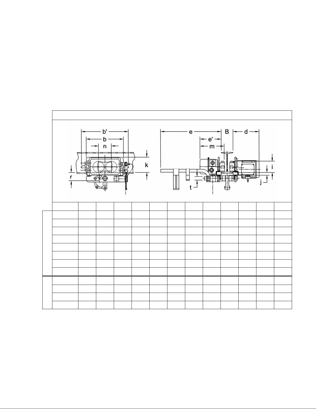
2.2 Dimensions
Humidity: 85% or less
Dual Speed - 40/20% ED with 120/240 starts per hour
Code b b' d e e' i j k m n r t
MR010L/S 12.4 15.6 8.7 20.3 7.0 3.74 0.9 5.1 8.0 4.3 2.0 1.22
MR020L/S 12.8 16.4 8.9 20.5 7.2 4.33 1.1 4.9 8.3 4.6 2.4 1.42
MR030L/S 13.4 17.4 8.9 20.5 7.3 4.92 1.1 5.2 8.5 5.2 2.7 1.69
MR050L/S 15.7 19.8 11.1 20.8 7.6 5.51 1.7 5.7 9.2 5.9 3.4 2.13
MR080L 19.7 22.9 11.2 20.9 8.6 6.89 3.5 6.9 10.4 7.5 6.0 2.76
Single Speed
MR100L 19.7 22.9 11.2 20.9 8.6 6.89 3.1 6.9 10.4 7.5 6.0 2.76
MR150L 40.2 43.4 11.2 20.9 8.6 6.89 3.3 6.9 10.4 28.0 6.0 2.76
MR200L 40.2 43.4 11.2 20.9 8.6 6.89 3.1 6.9 10.4 28.0 6.0 2.76
Table 2-2 Trolley Dimensions
MR010SD 12.4 15.6 10.6 20.3 7.0 3.74 0.9 5.1 8.0 4.3 2.0 1.22
MR020SD 12.8 16.4 10.7 20.5 7.2 4.33 1.1 4.9 8.3 4.6 2.4 1.42
MR030SD 13.4 17.4 10.8 20.5 7.3 4.92 1.1 5.2 8.5 5.2 2.7 1.69
Dual Speed
MR050SD 15.7 19.8 11.1 20.8 7.6 5.51 1.7 5.7 9.2 5.9 3.4 2.13
9
Page 10

3.0 Pre-operational Procedures
3.1 Assembly and Adjustment
3.1.1 When the MR trolley is combined with a hoist, follow and complete all pr e-operational procedu res
provided with the hoist. For Harrington ER and NER mo del hoists, follow the p re-operational
procedures in the ER/NER Owner's Manual in conjuncti on with all informati on provided in thi s section
for mounting and electrical connections.
3.1.2 In addition to the information and procedures provided i n this secti on for the MR trolley, there are
specific details for using ER and NER h oists with MR troll eys. Special mounting a nd wiring
considerations must be taken if the trolley is used with a hoist other tha n an ER or NER mo del.
3.1.3
WARNING
Never attempt to hook mount a hoist directly to the Suspension Shaft on trolleys
up to and including 5 Ton. These trolleys are de signed to be used with a suspender only an d do not
have the vertical clearance required for a hook to fit between t he Suspension Shaft a nd trolley beam .
3.1.4 Preparing ER and NER hoists for use wit h MR trolley.
1/8 to 3 Ton ER/NER – The standard susp ension co nfiguration u ses Suspender T which orient s the
hoist perpendicular to the trolley beam. Optional two-piec e suspension method u ses a Connection
Yoke and Suspender G, which orients the hoi st parallel to the troll ey beam. If the hoist is not eq uipped
with Suspender T or the Connection Yoke from th e factory, remove the Top Hook Assembly from the
hoist and install Suspender T or the Connection Yoke as follows:
1) Refer to Figure 3-1.
2) Remove the four Controller Cover so cket head bolts an d allow the co ver to swing fully open.
3) Loosen the three or four captive screws holding the electrical comp onent mounting Pla te against
the main body of the hoist and swing the plate out to access the req uired compone nts.
4) Loosen one of two Machine Screws attaching Pl ate A and remov e the second Machi ne Screw.
Allow Plate A to rotate out from the retaining slot in the bottom side of the Connection Shaft. Pull
out the Connection Shaft and remove the Top Hook Assembly.
5) Remove the Hoist Fixing Shaft.
6) Place Suspender T or the Connection Yoke on the top of the hoist. Line up t he holes for the
Connection Shaft and the Hoist Fixing Shaft and reinsert the shafts.
7) Reassemble the remaining hoist component s in reverse order of disassembly.
8) If installing the Connection Yoke, place the Connection Yoke Rubber and Suspender G in the top
of the Connection Yoke. Attach Suspender G to the Connection Yoke with the Yoke Bolt, Slotted
Nut and Split Pin (cotter pin).
9) There are two oil fill holes located in the top of the gear case on the ER hoist. For ER coupl ed to
MR trolley, there are some flange widths where it will be necessary to relocate the oil cap assembly
to the other oil fill hole. This will prevent interference with troll ey side plate.
3 Ton (030C) and 5 Ton ER/NER – The 3 Ton (030C) and 5 Ton ER/NER hoists (double fall) alwa ys
use a Connection Yoke. The standard suspension confi guration uses S uspender T which orient s the
hoist perpendicular to the trolley beam. Suspen der G is availabl e as an option an d orients the h oist
parallel to the trolley beam. If the hoist is not equipped with Suspender T or G from the factory, remove
the Top Hook Assembly from the Connection Yoke and install the Suspen der T or G as shown in
Figure 3-2.
8 to 20 Ton ER/NER – Since the trolley suspen sion shaft (s) passes throug h the hoist top pl ates, no
additional hoist preparation is required to mount the E R hoist to the trolley. Ho ok mount ER hoist s can
not be converted to lug mount without replaci ng the hoist's to p Suspension Plat es.
10
Page 11
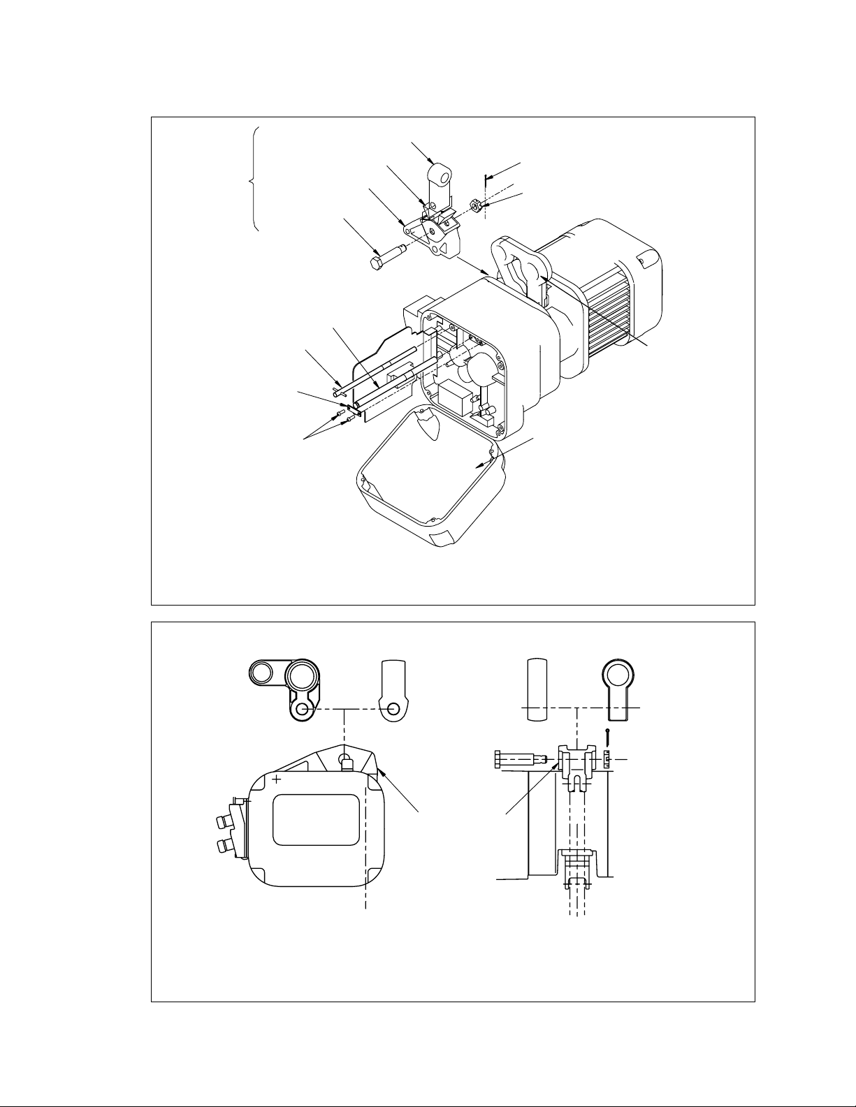
Suspender G
Split Pin
Slotted Nut
Suspender T
(Standard)
Optional
Hoist Fixing Shaft
(Retains Shaft)
Connection Yoke Rubber
Connection Yoke
Yoke Bolt
Connection
Shaft
Plate A
Machine Screw
& Spring Washer
Controller Cover Assembly
Figure 3-1 Installing Suspender T or Connection Yoke on ER Hoists –
Up Through 3 Ton (except 030C) Capacity
Suspender T
(Standard)
Suspender G
(Optional)
Suspender T
(Standard)
Yoke Bolt
Connection Yoke
Suspender G
(Optional)
Slotted Nut & Split Pin
Note: Unlike 3 Ton (Single Fall) and below (see Figure 3-1), Suspender G for 3 Ton (030C) and
5 Ton connects directly to the Connection Yoke without the Connection Yoke Rubber.
Figure 3-2 Installing Suspender T or G on 3 Ton (030C) and 5 Ton ER Hoists
11
Page 12

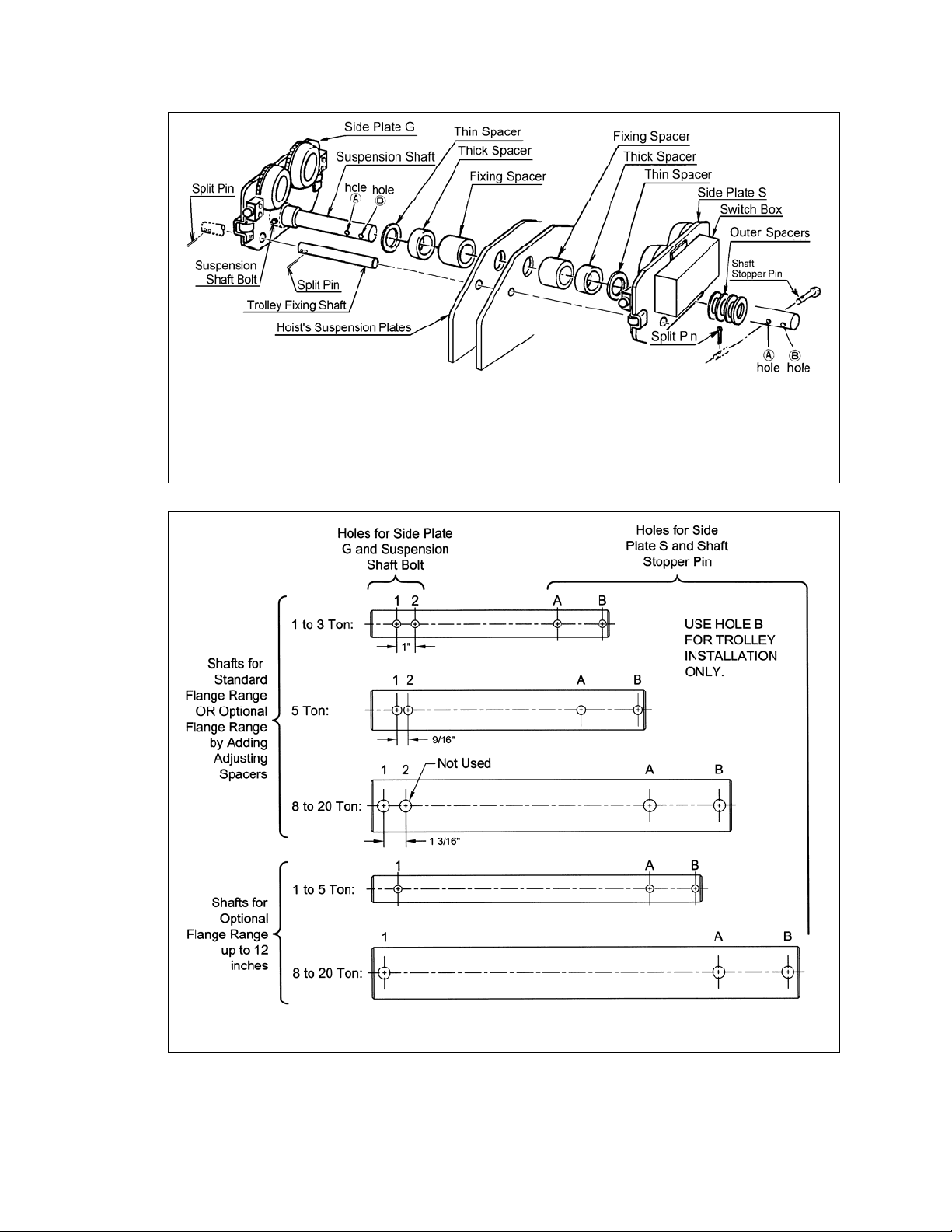
3.1.5 Trolley Assembly
1) Refer to Figure 3-3 or 3-4.
2) Remove the Shaft Stopper Pin, Side Plate S, and Spacers from th e Suspension S haft. For beam
flanges that are wider than the standard range, diffe rent suspension shaft an d/or spacer
arrangements are provided. Refer to Ta ble 3-1.
3) Insert the Suspension Shaft to Side Plate G and attach it with the Suspension Shaft Bolt, Slotted
Nut and Split Pin (cotter pin). Refer to Figure 3-5 and insure that correct Suspensi on Shaft holes
are used. Securely bend both branches of the Split Pin after insertion.
4) Referring to Figure 3-8, Table 3-1 and Table 3-2 install the inner adjusting Space rs and Suspen der
(Suspension Plates for 8 to 20 Ton) on the Suspension Shaft. Use all of the Spacers provided with
the trolley. If the beam width is not listed in Table 3-2, use the next size small er and ma ke
adjustments in accordance with Section 3.1.6.
5) Place Side Plate S into the Suspension Shaft.
6) Install the outer adjusting Spacers on the Suspen sion Shaft outside of Side Plate S. Insert the
Shaft Stopper Pin into Hole "A" so that Split Pin is to the left when seen from the front side of t rolley
switch box. Temporarily install the split pin in the Shaft Stopper Pi n and bend the split pin slightly to
hold it in place. The split pin should be fully bent after checking a nd attaining the proper beam
flange adjustment.
7) For ER Hoists up through 5 Ton with Su spender T - Insert the T rolley Fixing Shaft through Sid e
Plate G, Suspender T and Side Plate S. Secure it to Side Plate G with the two split pins. Securely
bend both branches of the Split Pin after insertio n.
8) For 8 and 10 Ton ER Hoists - Insert the Tr olley Fixing Shaft through Sid e Plate G, Suspension
Plates and Side Plate S. Secure it to Side Plate G with two split pins. Securely bend both
branches of the Split Pin after insertion.
Figure 3-3 Assembling the Trolley – Up Through 5 To n Capacity
12
Page 13
Note: 15 and 20 Ton trolleys use 2 Suspension Shafts and do not use Trolley Fixing Shafts.
is behind the Suspension Shaft.
Trolley Fixing Shaft is shown in front of Suspension Shaft for clarity. Actual location
Figure 3-4 Assembling the Trolley – 8 Through 20 To n Capacity
Figure 3-5 Suspension Shafts
13
Page 14
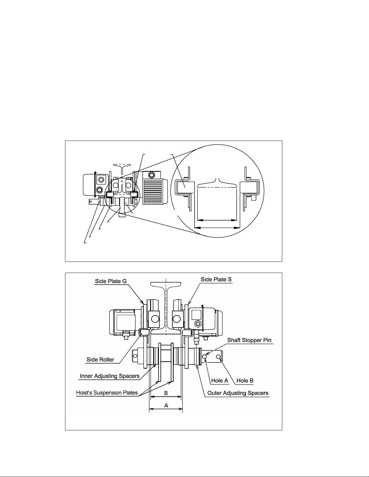
3.1.6 Adjusting the trolley width - After assembling trolley per Section 3.1.5, check the adjustment as follows:
1) Refer to Figure 3-6 or 3-7.
2) Make sure both side plates are spread fully outward and Meas ure Dimension "A". Compare
dimension "A" with the following values:
For trolleys up through 5 Ton, "A" must be 1/8 to 3/16" g reater than "B".
For trolleys 8 Ton and larger, "A" must be 7/32 to 9/32" g reater than "B".
3) If "A" does not fall within the specified range, move spacers from inner to outer or from outer to
inner as necessary to obtain the proper "A" dimension, irrespe ctive of the numbers in Tabl e 3-2.
4) After obtaining the proper adjustment, install the Shaft Stopper Pin in Hole A, insert the Split Pin
into the Shaft Stopper Pin, and securely bend both bra nches of the split pin.
Side Roller
Flange
Inner Adjusting Spacers
Suspender
Side Plate S
Outer Adjusting Spacers
Shaft Stopper Pin
B
A
Figure 3-6 Adjusting the Trolley – Up Through 5 Ton Ca pacity
Figure 3-7 Adjusting the Trolley – 8 Through 20 To n Capacity
14
Page 15
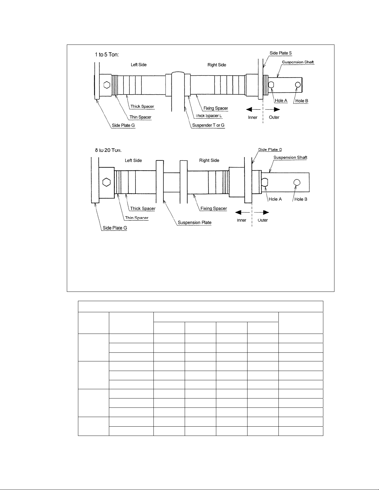
Note: Inner Spacer rows on Table 3-2 list two numbers. First number is the quantity of spacers located on the
left side of the Suspender or Suspension Plates, second number is the quantity on the right side.
Example: 1 + 2
Í Adjusting Spacers on the right side (Side Plate S side)
Ï
Adjusting Spacers on the left side (Side Plate G side)
Figure 3-8 Spacers Arrangement
Table 3-1 Suspension Shaft Adjusting Spacers, an d Suspension Sha ft Bolt
Capacity
(Tons)
1
2 & 3
5
8 and up
Flange Range
Total Number of Spacers Supplied
(in) Thin Thick Fixing Thick L
2.28 to 5.00 8 3
5.01 to 6.02 8 5
6.03 to 12.00 8 9 2 2 Hole 1
3.23 to 6.02 8 3
6.03 to 7.02 8 5
7.03 to 12.00 8 9 2 2 Hole 1
3.94 to 7.01 8 3
7.02 to 7.60 8 4
7.61 to 12.00 8 13
5.91 to 8.66 8 6
8.67 to 12.00 8 7 2
⎯
⎯
⎯
⎯
⎯
⎯
⎯
⎯ ⎯
2 Hole 2
2 Hole 1
2 Hole 2
2 Hole 1
2 Hole 2
2 Hole 1
2 Hole 1
⎯
Suspension
Shaft Bolt
Location
Hole 1
Hole 1
15
Page 16

Page 17
16
Flange
Cap.
(Ton)
1
2
and
3
5
8
thru
20
Beam
Width
Spacer
Type
Thin
Thick
Fixing
Thick
Thin
Thick
Fixing
Thick
Thin
Thick
Thick
Thin
Thick
Fixing
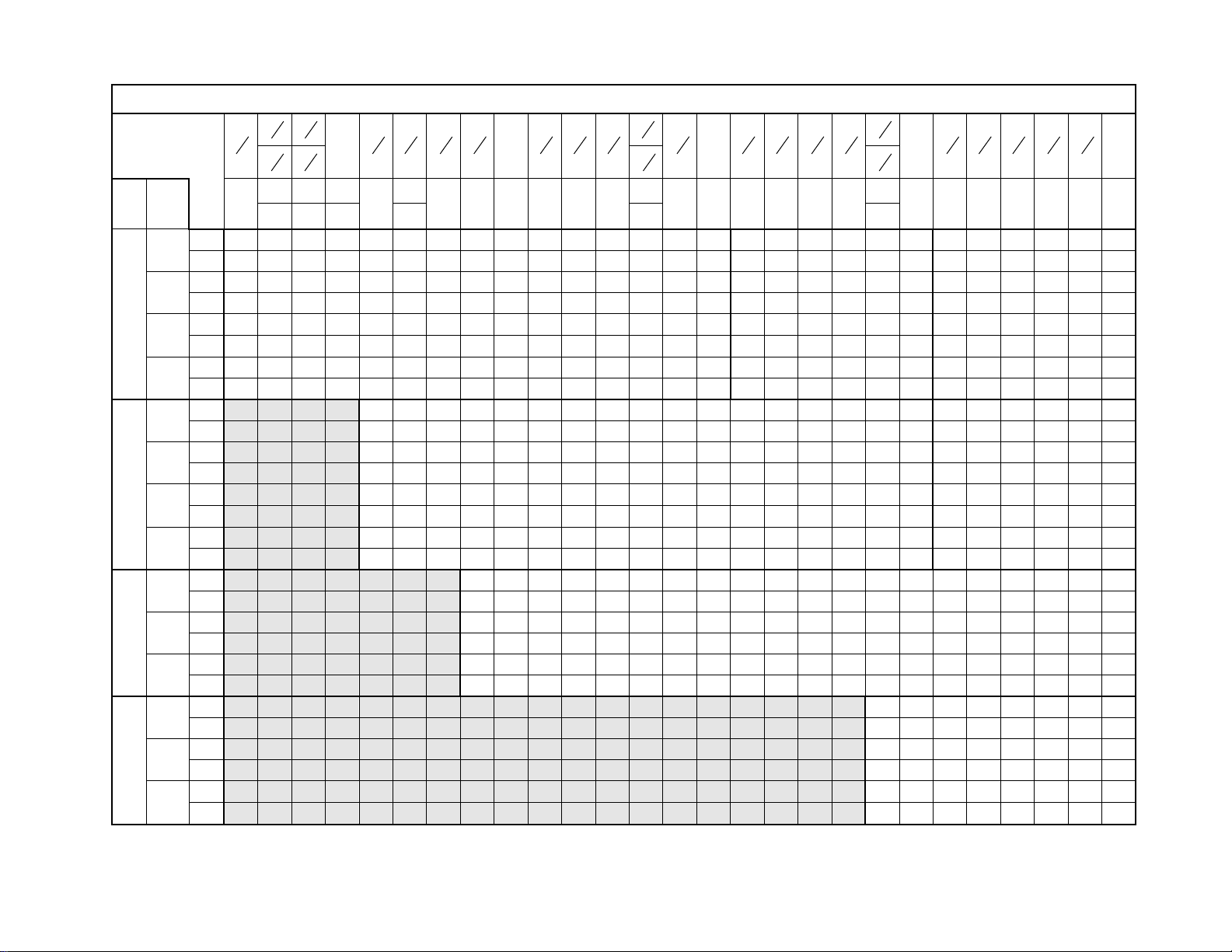
Table 3-2 Number of Adjusting Spacers
1
7
2
2
2
(in)
(mm)
5
2
16
2
58
8
5
8
3
15
2
16
64 73 75 90 119 149
66 74 76
9
1
3
3
4
16
82
15
7
3
3
8
16
3
5
4
4
4
16
16
98 100 102 106 110 113
91
Inner 1+2 2+3 4+4 1+0 1+2 2+3 0 1+0 1+0 1+2 2+2 2+3 3+4 4+4 4+1 5+1 2+2 2+2 3+3 4+4 4+1 1+1 2+2 2+3 3+0 4+4 4+1
Outer 5 3 0 7 5 3 8 7 7 5 4 3 1 0 3 2 4 4 2 0 3 6 4 3 5 0 3
Inner 0+0 0+0 0+0 0+0 0+0 0+0 1+1 1+1 1+1 1+1 1+1 1+1 1+1 1+1 1+2 1+2 2+2 2+2 2+2 2+2 2+2 3+3 3+3 3+3 3+4 3+3 3+4
Outer 3 3 3 3 3 3 1 1 1 1 1 1 1 1 0 2 1 1 1 1 1 3 3 3 2 3 2
Inner
⎯ ⎯ ⎯ ⎯ ⎯ ⎯ ⎯ ⎯ ⎯ ⎯ ⎯ ⎯ ⎯ ⎯ ⎯ ⎯ ⎯ ⎯ ⎯ ⎯ ⎯
Outer
⎯ ⎯ ⎯ ⎯ ⎯ ⎯ ⎯ ⎯ ⎯ ⎯ ⎯ ⎯ ⎯ ⎯ ⎯ ⎯ ⎯ ⎯ ⎯ ⎯ ⎯
Inner 0+0 0+0 0+0 1+1 1+1 1+1 1+1 1+1 1+1 1+1 1+1 1+1 1+1 1+1 1+1 1+1 1+1 1+1 1+1 1+1 1+1 1+1 1+1 1+1 1+1 1+1 1+1
L
Outer 2 2 2 0 0 0 0 0 0 0 0 0 0 0 0 0 0 0 0 0 0 0 0 0 0 0 0
Inner 1+2 2+3 3+4 0 1+0 1+1 1+2 2+2 3+3 4+4 1+0 1+1 1+2 2+2 3+3 4+0 4+1 1+1 1+2 2+2 3+3 4+4 1+4
Outer
5 3 1 8 7 6 5 4 2 0 7 6 5 4 2 4 3 6 5 4 2 0 3
Inner 0+0 0+0 0+0 0+0 0+0 0+0 0+0 0+0 0+0 0+0 1+1 1+1 1+1 1+1 1+1 1+2 1+2 2+2 2+2 2+2 2+2 2+2 3+2
Outer
Inner
Outer
3 3 3 3 3 3 3 3 3 3 1 1 1 1 1 0 0 1 1 1 1 1 0
⎯ ⎯ ⎯ ⎯ ⎯ ⎯ ⎯ ⎯ ⎯ ⎯ ⎯ ⎯ ⎯ ⎯ ⎯ ⎯ ⎯ ⎯ ⎯ ⎯ ⎯ ⎯ ⎯
⎯ ⎯ ⎯ ⎯ ⎯ ⎯ ⎯ ⎯ ⎯ ⎯ ⎯ ⎯ ⎯ ⎯ ⎯ ⎯ ⎯ ⎯ ⎯ ⎯ ⎯ ⎯ ⎯
Inner 0+0 0+0 0+0 1+1 1+1 1+1 1+1 1+1 1+1 1+1 1+1 1+1 1+1 1+1 1+1 1+1 1+1 1+1 1+1 1+1 1+1 1+1 1+1
L
Outer
2 2 2 0 0 0 0 0 0 0 0 0 0 0 0 0 0 0 0 0 0 0 0
Inner 0+0 1+0 1+1 1+2 2+2 3+3 0 1+0 1+1 2+2 2+2 3+3 4+0 4+1 1+1 2+2 2+3 3+0 4+4 4+1
Outer
8 7 6 5 4 2 8 7 6 4 4 2 4 3 6 4 3 5 0 3
Inner 0+0 0+0 0+0 0+0 0+0 0+0 0+0 0+0 0+0 0+0 0+0 0+0 0+1 0+1 1+1 1+1 1+1 1+2 1+1 1+2
Outer
3 3 3 3 3 3 3 3 3 3 3 3 2 2 1 1 1 0 1 0
Inner 0+0 0+0 0+0 0+0 0+0 0+0 1+1 1+1 1+1 1+1 1+1 1+1 1+1 1+1 1+1 1+1 1+1 1+1 1+1 1+1
L
Outer
2 2 2 2 2 2 0 0 0 0 0 0 0 0 0 0 0 0 0 0
Inner 1+1 1+2 1+2 2+3 3+3 4+4 1+1 1+2
Outer
6 5 5 3 2 0 6 5
Inner 1+1 1+1 1+1 1+1 1+1 1+1 2+2 2+2
Outer
4 4 4 4 4 4 2 2
Inner
Outer
11
4
16
7
4
16
15
4
16
3
4
4
5
3
5
5
16
5
3
5
16
8
125 127 131 135 137 143
120
7
5
8
5
5
8
6
15
5
16
5
1
6
8
7
6
16
11
6
6
16
6
16
153 155 160 163 170 175 178
150
0 0 0 0 0 0
2 2 2 2 2 2
⎯ ⎯ ⎯ ⎯ ⎯ ⎯ ⎯ ⎯
⎯ ⎯ ⎯ ⎯ ⎯ ⎯ ⎯ ⎯
7
7
8
Page 18

17
Flange
Cap.
(Ton)
1
2
and
3
5
8
thru
20
Beam
Width
Spacer
Type
Thin
Thick
Fixing
Thick
Thin
Thick
Fixing
Thick
Thin
Thick
Thick
Thin
Thick
Fixing
Table 3-2 Number of Adjusting Spacers (continued)
1
7
(in)
7
(mm)
Inner 1+1 1+2 4+4 5+0 2+3 3+4 1+1 1+2 4+0 1+1 1+2 2+2 2+3 3+3 1+1 1+2 2+2 2+3 3+0 4+0 4+1 4+1 4+2
Outer 6 5 0 3 3 1 6 5 4 6 5 4 3 2 6 5 4 3 5 4 3 3 2
Inner 0+0 0+0 0+0 0+1 1+1 1+1 2+2 2+2 2+3 3+3 3+3 3+3 3+3 3+3 4+4 4+4 4+4 4+4 4+5 4+5 4+5 4+5 4+5
Outer 9 9 9 8 7 7 5 5 4 3 3 3 3 3 1 1 1 1 0 0 0 0 0
Inner 1+1 1+1 1+1 1+1 1+1 1+1 1+1 1+1 1+1 1+1 1+1 1+1 1+1 1+1 1+1 1+1 1+1 1+1 1+1 1+1 1+1 1+1 1+1
Outer 0 0 0 0 0 0 0 0 0 0 0 0 0 0 0 0 0 0 0 0 0 0 0
Inner 1+1 1+1 1+1 1+1 1+1 1+1 1+1 1+1 1+1 1+1 1+1 1+1 1+1 1+1 1+1 1+1 1+1 1+1 1+1 1+1 1+1 1+1 1+1
L
Outer 0 0 0 0 0 0 0 0 0 0 0 0 0 0 0 0 0 0 0 0 0 0 0
Inner 1+1 1+2 4+4 1+0 2+3 3+3 4+1 1+1 4+4 4+1 5+1 4+3 2+3 3+3 4+1 1+2 2+2 2+3 3+3 3+4 4+4 4+1 5+1
Outer 6 5 0 7 3 2 3 6 0 3 2 1 3 2 3 5 4 3 2 1 0 3 2
Inner 0+0 0+0 0+0 1+1 1+1 1+1 1+2 2+2 2+2 2+3 2+3 2+3 3+3 3+3 3+4 4+4 4+4 4+4 4+4 4+4 4+4 4+5 4+5
Outer 9 9 9 7 7 7 6 5 5 4 4 4 3 3 2 1 1 1 1 1 1 0 0
Inner 1+1 1+1 1+1 1+1 1+1 1+1 1+1 1+1 1+1 1+1 1+1 1+1 1+1 1+1 1+1 1+1 1+1 1+1 1+1 1+1 1+1 1+1 1+1
Outer 0 0 0 0 0 0 0 0 0 0 0 0 0 0 0 0 0 0 0 0 0 0 0
Inner 1+1 1+1 1+1 1+1 1+1 1+1 1+1 1+1 1+1 1+1 1+1 1+1 1+1 1+1 1+1 1+1 1+1 1+1 1+1 1+1 1+1 1+1 1+1
L
Outer 0 0 0 0 0 0 0 0 0 0 0 0 0 0 0 0 0 0 0 0 0 0 0
Inner 1+0 1+1 4+4 1+0 2+3 3+4 1+1 1+2 4+4 1+1 1+2 2+2 2+3 3+3 5+1 1+2 2+2 2+3 4+3 4+4 4+0 4+1 5+1
Outer 7 6 0 7 3 1 6 5 0 6 5 4 3 2 2 5 4 3 1 0 4 3 2
Inner 2+2 2+2 2+2 3+3 3+3 3+3 4+4 4+4 4+4 5+5 5+5 5+5 5+5 5+5 5+6 6+6 6+6 6+6 6+6 6+6 6+7 6+7 6+7
Outer 0 0 9 7 7 7 5 5 5 3 3 3 3 3 2 1 1 1 1 1 0 0 0
Inner 1+1 1+1 1+1 1+1 1+1 1+1 1+1 1+1 1+1 1+1 1+1 1+1 1+1 1+1 1+1 1+1 1+1 1+1 1+1 1+1 1+1 1+1 1+1
L
Outer 0 0 0 0 0 0 0 0 0 0 0 0 0 0 0 0 0 0 0 0 0 0 0
Inner 2+2 2+3 1+1 1+2 3+3 4+4 1+1 1+2 4+4 1+1 1+2 2+2 2+3 3+3 1+1 1+2 2+2 2+3 3+4 4+0 4+0 4+1 5+1
Outer 4 3 6 5 2 0 6 5 0 6 5 4 3 2 6 5 4 3 1 4 4 3 2
Inner 2+2 2+2 3+3 3+3 3+3 3+3 1+1 1+1 1+1 2+2 2+2 2+2 2+2 2+2 3+3 3+3 3+3 3+3 3+3 3+4 3+4 3+4 3+4
Outer 2 2 0 0 0 0 5 5 5 3 3 3 3 3 1 1 1 1 1 0 0 0 0
Inner
Outer
1
7
16
4
5
1
7
8
16
180 184
7
7
8
200 203 215 220 229 232 250 254 257 260 264 267 279 283 286 289 295 298 300 302 305
7
8
8
8
16
181 185
⎯ ⎯ ⎯ ⎯ ⎯ ⎯
⎯ ⎯ ⎯ ⎯ ⎯ ⎯
11
16
1
7
9
9
9
8
10
8
1
10
10
8
3
1
10
4
1
10
8
2
11
1
11
11
8
3
5
3
1
11
11
4
8
11
8
13
11
4
16
1+1 1+1 1+1 1+1 1+1 1+1 1+1 1+1 1+1 1+1 1+1 1+1 1+1 1+1 1+1 1+1 1+1
0 0 0 0 0 0 0 0 0 0 0 0 0 0 0 0 0
7
11
8
12
Page 19

Page 20
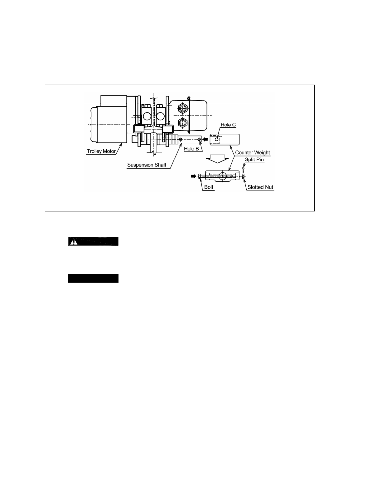
3.1.7 Counter Weight – For proper balance 1 T on, dual speed MR trolleys (code MR01 0SD) require a
Counter Weight when installed on a 3 7/8 inch or smalle r beam flange. The Co unter Weight mounts on
the Suspension Shaft as shown in Figure 3 -9 and is held in place with a Bolt, Slotted Nut and Split Pin.
The bolt is installed through holes B and C. Make sure t he weight is securely fastened to the shaft and
that the split pin is properly bent. All other trolley capacities do NOT re quire a counter weig ht.
Figure 3-9 Counter Weight installation for 1 Ton dual speed t rolleys o n
beam flanges 3 7/8 inch or smaller
3.2 Mounting Location
3.2.1
3.2.2
WARNING
supporting structure are adequat e to support th e trolley, hoist and it s loads. If necessary consult a
professional that is qualified to evaluate the ade quacy of the suspen sion location and it s supporti ng
structure.
NOTICE
Prior to mounting the trolley (and hoist) ensure that the trolley beam and its
See Section 6.4 for outdoor installation considerations.
3.3 Installation of Trolley onto Beam
3.3.1 Assemble and adjust the trolley before attempting to install the trolley on the beam.
3.3.2 Preferred Method – Sliding the trolley connected with an electric chain hoist onto the traver sing beam
from the beam end is the most convenient and re commended metho d. If the trolley can be mount ed
from the end of the beam then: Remove the trolley end -stop from the beam an d set the trolley on the
beam from the end. Securely re-install the trolley end stop on t he beam.
3.3.3 Optional Method for Trolleys Up to 5 Ton – If the troll ey cannot be mounted from the end of the bea m,
complete the installation as follows:
1) Move the Shaft Stopper Pin to Hole B (see Figure 3-10).
2) Spread the trolley side plates apart.
3) Lift the trolley onto the beam so that the geared wheels (motor sid e of trolley) rest on the beam's
flange.
4) Hold Side Plate G securely so that it does not come off the b eam then push th e side plates
together so that all four wheels rest on the beam's flange .
5) Remove the Shaft Stopper Pin from Hole B and re-inst all in Hole A (see Figure 3-5). Bend t he Split
Pin securely. Never use trolley with Shaft Stopper Pin in Hole B. Hole B is ONLY used when
installing the trolley on the beam.
18
Page 21

Figure 3-10 Optional trolley installation method – up to 5 Ton
3.3.4 Optional Method for 8 to 20 Ton Trolley with hoist - refer to Figure 3-11.
WARNING
ALWAYS install the trolley onto the beam before installing the hoist to the trolley.
Attempting to install a pre-assembled hoist and trolley ont o the beam other than onto the beam end
(per Section 3.3.2) is dangerous a nd must not be attempt ed.
1) Assemble and adjust the trolley.
2) Separate trolley the trolley from the hoist by removing the Suspension Shaft(s), Adjusting spacers
and Trolley Fixing Shaft (8 and 10 Ton only). Reassem ble the trolley without t he hoist by
reinstalling the Suspension Shaft(s), Trolley Fixing Shaft and o uter Adjusting Spa cers. Place inner
spacers aside until step (6).
3) Install the trolley on the beam by following steps (1 ) to (5) of Section 3. 3.3.
4) Use safe and proper rigging practices to secure the trolley side plate s so that they will remain firmly
in place after the Suspension Shaft(s) and Trolley Fixing Shaft are removed (next step).
5) Remove the Suspension Shaft(s), Trolley Fixing Shaft and o uter Adjusting Spa cers.
6) Move the hoist up into position between the trolley sid e plates and line up th e trolley and hoist's
Suspension Shaft holes.
7) Connect the hoist to the trolley by reinstalling the Suspension Shaft(s), Trolley Fixing Shaft,
Adjusting Spacers, Suspension Shaft Bolt(s), and Shaft Stopper Pin(s).
8) Ensure that:
Shaft Stopper Pin(s) is(are) in hole A of the Suspension Shaft(s).
Split Pins are installed properly.
Trolley is properly adjusted (refer to Section 3.1.6).
19
Page 22

Figure 3-11 Optional trolley installation method – 8 Ton and Larger
3.4 Electrical Connections
3.4.1
3.4.2
3.4.3
3.4.4 This instruction applies to installation s where an ER or NE R model elect ric hoist is inst alled on an MR
CAUTION
CAUTION
trolley. Use of such devices may cause the motor brake and other electrical components to
malfunction. Variable frequency drives MAY be used with MR trolleys, contact Harrington for more
information.
DANGER
been de-energized (disconnected). Lock out and tag out in a ccordance with ANSI Z 244.1 “Personnel
Protection -Lockout/Tagout of Energy Sources”.
trolley. In this case the hoist and trolley are controlled by a pendant wit h four push buttons – two for the
hoist motion and two for the trolley motion. Special wiring considerations must be taken if the trolley is
used with a hoist other than an ER or NER mod el.
Pendant Cord - The Pendant Cord connects to the trolley via an 8-pin (8P) Plug and Socket. Make
this connection as follows:
1) Refer to Figure 3-12 or 3-13 depending on the product code of the t rolley/hoist.
2) Insert the 8P Plug into the 8P Socket on the Switch Box and hand tig hten the Screw Co upling.
3) For trolley/hoist code ERM001H to ERM100L – Install t he Cord Strain Relief Cable to the Cord
Support on the Bar Holder.
Ensure that the voltage of the electric power supply is prope r for the hoist or trolley.
Do NOT apply electronic soft-start control or voltage varying controls to the MR
Before proceeding, ensure that the electrical supply for t he hoist or trolley has
4) For trolley/hoist code ERM100S – install the Cord St rain Relief Cab le onto Cord Strain Rel ief
Stopper located at the 8P socket.
5) For trolley/hoist code ERM150S and ERM200S – Install the Co rd Strain Relief Cable onto
Connection Plate S.
20
Page 23

Power Supply Cable Hoist Connection – The Power Supply Cabl e conne cts directly to the trolley's
Switch Box using Cable Holder Assembly. Make this conne ction as fol lows:
1) Refer to Figure 3-12 or 3-13 depending on the product code of the t rolley/hoist.
2) With 1 inch of the outer cable insulation extendi ng beyond the cable packin g, insert the cable int o
the switch box and screw together Cable Holde r A and B.
3) Refer to Figure 3-14 and connect the blac k, red and white wi res to terminals 1, 2, a nd 3 on the
terminal strip inside the Switch Box. Co nnect the groun d wire (green wi th yellow strip e or solid
green) to the ground terminal next to the terminal strip.
4) Install the Cable Support Assembly (pre-i nstalled on the Power Supply Cable ) onto the Cable
Support Arm Assembly as shown in Figure 3-15.
5) Use care to avoid twisting or kinking the Po wer Supply Cable.
Trolley to Hoist Connections – The t rolley connects to t he hoist via short cables that are f actory
installed into the trolley Switch Box. The Cables are fitted with plug assem blies that match sockets in
the hoist bodies. Make these connections as follows:
1) Refer to Figure 3-12 or 3-13 depending on the product code of the t rolley/hoist.
2) Insert the 4P Plug(s) into the 4P Socket(s) on the hoist and hand tight en the Screw Coupl ing(s).
3) Insert the 5P Plug(s) into the 5P Socket(s) on the hoist and hand tight en the Screw Coupl ing(s).
Power Supply Cable Festooning – The MR trolley is stand ardly supplied with Cable Hanger s for the
Power Supply Cable. Make this connection as follows:
1) Refer to Figure 3-15.
2) Install the Cable Hangers onto the Power Supply Cabl e spacing them every 5 feet.
3) Install a Guide Wire system parallel to th e beam. Pass the G uide Wire throug h the Cable Hanger s
and Wire Guide.
4) Make sure the Guide Wire is prope rly tensioned a nd the Power Supply Cable is not t wisted or
kinked.
3.4.5 Connection to Electrical Power Source - The black, red and white wires of the Power Supply Cable
should be connected to an Electric Power Disconnect Switch or Circuit Breaker. This connection
should be made so that the ER, NER or other ho ist is phased prop erly. Refer to Section 3. 5.5 for
instructions on how to check for correct power supply phase connection.
3.4.6 Fuse/Breaker Capacity -The power supply for th e trolley and hoist should be equipp ed with overcurrent
protection such as fuses, which should be selected for 110% to 120% of total listed full load amp erage,
and should be dual element time-delay fuses. Refer to t he motor namepl ates on the trolley and h oist
for the full load amperage draw of each and added the t wo values togethe r for the total ampe rage.
3.4.7
DANGER
Grounding - An improper or insufficient gr ound connecti on creates an electrical
shock hazard when touching any part of the hoi st or trolley. In the Power Supp ly Cable the ground wi re
will be either Green with Yellow stripe or solid Green. It should always be connect ed to a suitable
ground connection. Do not paint the trolley wheel ru nning surfa ces of the beam as this can affect
grounding.
21
Page 24

Figure 3-12 Pendant and Power Supply Cable Connection – Product Code ERM 001H to ERM100L
Figure 3-13 Pendant and Power Supply Cable Connection - Product Code ERM 100S to ERM200S
22
Page 25

Figure 3-14 Power supply cable terminal connections.
Figure 3-15 Power Supply Cable installation and Guide Wire location.
23
Page 26

3.5 Pre-operational Checks and Trial Operation
3.5.1 Refer to the trolley's Nameplate and record the Cod e, Lot and Serial Number in the space provided on
the cover of this manual.
3.5.2 Refer to the hoist's owner's manual an d perform all pr e-operational checks fo r the hoist.
3.5.3 Perform pre-operational checks for the trolley:
Ensure that trolley is properly installed on the beam, and stops for t he trolley are correctly
Ensure that all nuts, bolts and split pins (cotter pins) are suffici ently fastened.
Pull down on the Pendant and ensure that the Cord Strain Relief Cable takes the force, not the
3.5.4 Confirm proper operation.
Before operating read and become familiar with Section 4 - Operation.
Before operating ensure that the hoist (and trolley) m eets the Inspection , Testing and Maint enance
Before operating ensure that nothing will interfere with the full range of the hoist’s (and troll ey’s)
3.5.5 Proceed with trial operation to confirm proper ope ration.
Verify that the controls agree with hoist direction. Make sure that depressio n of the Up button lifts
WARNING
and all other lifting attachments before u se. Inspect all l oad suspen sion membe rs for damag e prior
to use and replace or repair all damaged part s.
positioned and securely installed on the beam.
Pendant Cord.
CAUTION
10% of the rated value, electrical devices may not function normally.
requirements of ANSI/ASME B30.16.
operation.
the load chain and depression of the Down button lo wers the load chain hook. If the l oad chain
does not move in the correct direction when the push but tons are pushed, th e power supply is
phased incorrectly. In this case, turn off the power source or breaker switch
of the three wires at the power source. The hook will then move in accordance with the directions
of the push button.
Confirm the adequacy of the rated capacity for all slings, chains, wire ropes
Check supply voltage before everyday use. If the voltage varie s more than
then reverse any two
Operate the trolley though it's full range of motion. Make su re the trolley runs smoothly and does
not bind. Check the power supply and fest oon system f or prope r operation
Perform inspections per Section 5.3, “Frequent Inspections”.
24
Page 27

4.0 Operation
4.1 Introduction
DANGER
DO NOT
WALK UNDER A SUSPENDED LOAD
WARNING
HOIST OPERATORS SHALL BE REQUIRED TO READ THE OPERATION SECTION OF THIS MANUAL, THE
WARNINGS CONTAINED IN THIS MANUAL, INSTRUCTION AND WARNING LABELS ON THE HOIST OR
LIFTING SYSTEM, AND THE OPERATION SECTIONS OF ANSI/ASME B30.16 and ANSI/ASME B30.10. THE
OPERATOR SHALL ALSO BE REQUIRED TO BE FAMILIAR WITH THE HOIST AND HOIST CONTROLS
BEFORE BEING AUTHORIZED TO OPERATE THE HOIST OR LIFTING SYSTEM.
HOIST OPERATORS SHOULD BE TRAINED IN PROPER RIGGING PROCEDURES FOR THE ATTACHMENT
OF LOADS TO THE HOIST HOOK.
HOIST OPERATORS SHOULD BE TRAINED TO BE AWARE OF POTENTIAL MALFUNCTIONS OF THE
EQUIPMENT THAT REQUIRE ADJUSTMENT OR REPAIR, AND TO BE INSTRUCTED TO STOP OPERATION IF
SUCH MALFUNCTIONS OCCUR, AND TO IMMEDIATELY ADVISE THEIR SUPERVISOR SO CORRECTIVE
ACTION CAN BE TAKEN.
HOIST OPERATORS SHOULD HAVE NORMAL DEPTH PERCEPTION, FIELD OF VISION, REACTION TIME,
MANUAL DEXTERITY, AND COORDINATION.
HOIST OPERATORS SHOULD NOT
CONTROL, PHYSICAL DEFECTS, OR EMOTIONAL INSTABILITY THAT COULD RESULT IN ACTIONS OF THE
OPERATOR BEING A HAZARD TO THE OPERATOR OR TO OTHERS.
HOIST OPERATORS SHOULD NOT
INFLUENCE OF ALCOHOL, DRUGS, OR MEDICATION.
OVERHEAD HOISTS ARE INTENDED ONLY FOR VERTICAL LIFTING SERVICE OF FREELY SUSPENDED
UNGUIDED LOADS. DO NOT
ARE NOT FREELY SUSPENDED, OR LOADS THAT ARE GUIDED.
HAVE A HISTORY OF OR BE PRONE TO SEIZURES, LOSS OF PHYSICAL
OPERATE A HOIST OR LIFTING SYSTEM WHEN UNDER THE
USE HOIST FOR LOADS THAT ARE NOT LIFTED VERTICALLY, LOADS THAT
NOTICE
• Read ANSI/ASME B30.16 and ANSI/ASME B30.10.
• Read the hoist manufacturer’s Operating and Mai ntenance Instructi ons.
• Read all labels attached to equipment.
25
Page 28

The operation of an overhead hoist involves more than activating the hoist’s controls. Per the ANSI/ASME B30
standards, the use of an overhead hoist is subject to certain hazards that cannot be mitigated by engineered features,
but only by the exercise of intelligence, care, common sense, and experience i n anticipating the eff ects and result s of
activating the hoist’s controls. Use this guidance in conjunction with ot her warnings, ca utions, and notice s in this manual
to govern the operation and use of your overhead hoist.
4.2 Shall’s and Shall Not’s for Operation
WARNING
Improper operation of a hoist can create a potentially hazar dous
situation which, if not avoided, could result in death
injury, and substantial property damage. To avoid such a
potentially hazardous situation THE OPERATOR SHALL:
• NOT lift more than rated load for the hoist.
• NOT
• NOT
• NOT
• NOT
• NOT
• NOT
• NOT
• NOT
• NOT
• NOT
• NOT
• NOT
• NOT
• NOT
• NOT operate hoist with missing/damaged chain
operate unless load is centered under hoist.
use damaged hoist or hoist that is not wo rking
properly.
use hoist with twisted, kinked, damaged, or
worn chain.
use hoist if the bottom hook is capsized
(double fall hoists - see Section 3.2).
use the hoist to lift, support, or transport
people.
lift loads over people.
apply load unless load chain is properly
seated in the load sheave (and idle sheav e for hoi st
with two chain falls).
use the hoist in such a way that could re sult in
shock or impact loads being applie d to the hoist.
attempt to lengthen the load chain or repair
damaged load chain.
operate hoist when it is restricted from forming
a straight line from hook to hook in the direction of
loading.
use load chain as a sling or wrap load chain
around load.
apply the load to the tip of the hook or to the
hook latch.
apply load if binding prevents equal loading
on all load-supporting chains.
operate beyond the limits of the load chain
travel.
springs, cushion rubbe rs, stopp ers or st riker p lates.
or serious
• NOT
• NOT
• NOT
• NOT
• NOT
• Be familiar with operating controls, procedures, and
• Make sure the unit is securely attached to a
• Make sure load slings or other approved single
• Take up slack carefully - make sure load is
• Make sure all persons stay clear of the supported
• Protect the hoist’s load chain from weld splatter or
• Report Malfunctions or unusual performances
• Make sure hoist limit switches function properly.
• Warn personnel before lifting or moving a load.
• Warn personnel of an approaching load.
leave load supported by the hoist unattended
unless specific precautions have been taken.
allow the chain, or hook to be used as an
electrical or welding ground.
allow the chain, or hook to be touched by a
live welding electrode.
remove or obscure the warnings on the hoist.
operate a hoist on which the safety placards
or decals are missing or illegible.
warnings.
suitable support before applying l oad.
attachments are properly sized, rigged, and seated
in the hook saddle.
balanced and load-holding action is secure before
continuing.
load.
other damaging contaminants.
(including unusual noises) of the hoist and remove
the hoist from service until the malfunction or
unusual performance is resolved.
26
Page 29

CAUTION
Improper operation of a hoist can create a potentially hazar dous
situation which, if not avoided, could result in minor
, or property damage. To avoid such a potentially hazardous
injury
situation THE OPERATOR SHALL:
• Maintain a firm footing or be otherwise secured
when operating the hoist.
• Check brake function by tensioning the hoist prior
to each lift operation.
• Use hook latches. Latches are to retain slings,
chains, etc. under slack conditions only.
• Make sure the hook latches are closed and not
supporting any parts of the load.
• Make sure the load is free to move and will clear all
obstructions.
• Avoid swinging the load or hook.
• Make sure hook travel is in the same direction as
shown on controls.
• Inspect the hoist regularly, replace damaged or
worn parts, and keep appropriate records of
maintenance.
or moderate
• Use the hoist manufacturer’s recommended parts
when repairing the unit.
• Lubricate load chain per hoist manufacturer’s
recommendations.
• NOT
• NOT
• NOT
• NOT
• NOT
use the hoist load limiting or warning device to
measure load.
use limit switches as routine operating stops.
They are emergency devices only.
allow your attention to be diverted from
operating the hoist.
allow the hoist to be subjected to sharp
contact with other hoists, structures, or objects
through misuse.
adjust or repair the hoist unless qualified to
perform such adjustments or repairs.
4.3 Trolley and Hoist Controls
4.3.1 Single Speed Pendant Control - When using the pendant
control depress the Up button to raise the hoist's hoo k or the
Down button to lower the hoist's hook as sho wn in Figure 4-1.
Depress the Forward and Reverse buttons to move the
trolley horizontally. To stop motion release the buttons.
4.3.2 Dual Speed Pendant Control – Pendant controls supplied
with dual speed hoists or trolleys have two step cont rol
buttons. For low speed depress the butt on to the first step
and for high speed depress the button fully to the second
step. Use the Up button to raise the hoist's hoo k or the Down
button to lower the hoist's hook as shown in Figure 4 -1.
Depress the Forward and Reverse buttons to move the
trolley horizontally. To stop motion release the buttons.
4.3.3 Trolley with Two Button Pendant – When a motorize d trolley
is supplied with a two button pendant, the penda nt buttons
control the trolley's horizontal motion in the forward and
reverse directions. Single and dual speed buttons f unction
identical to the four button pendant described above.
4.3.4
CAUTION
before reversing direction.
Make sure the motor comple tely stops
Figure 4-1 Push Button
Pendant Control
27
Page 30

5.0 Inspection
5.1 General
5.1.1 The inspection procedure herein is based on ANSI/ASME B30.16. The following definitions are from
ANSI/ASME B30.16 and pertain to the inspection procedure below.
Designated Person - a person selected or assigned as being compete nt to perform the sp ecific duties
to which he/she is assigned.
Qualified Person - a person who, by possession of a recogni zed degree or certifi cate of professi onal
standing, or who, by extensive knowledge, train ing, and experience, has successf ully demonstrated the
ability to solve or resolve problems relating to the subject matter and work.
Normal Service - that distributed service which involve s operation wit h randomly di stributed lo ads
within the rated load limit, or uniform loads less than 65% of rated load for not more than 25% of the
time.
Heavy Service - that service which involves operation within the rated load limit which excee ds normal
service.
Severe Service - that service which involves normal o r heavy service with abnormal ope rating
conditions.
5.2 Inspection Classification
5.2.1 Initial Inspection - prior to initial use, all new, re-installed, altered, or modified trolleys shall be inspected
by a designated person to ensure compliance with the a pplicable provisio ns of this manual.
5.2.2 Inspection Classification - the inspection proced ure for trolleys in regular se rvice is divided into t wo
general classifications based upo n the intervals at which i nspection sho uld be perform ed. The intervals
in turn are dependent upon the nature of the criti cal components of the t rolley and the deg ree of their
exposure to wear, deterioration, or malfunction. The two general classificati ons are herein designated
as FREQUENT and PERIODIC, with respectiv e intervals betwee n inspections as de fined below.
5.2.3 FREQUENT Inspection - visual examinations by the operator or oth er designated personnel with
intervals per the following criteria:
Normal service - monthly
Heavy service - weekly to monthly
Severe service - daily to weekly
Special or infrequent service - as recommended by a q ualified person befo re and after e ach
occurrence.
5.2.4 PERIODIC Inspection - visual inspection by a designated person with intervals per the following criteri a:
Normal service - yearly
Heavy service - semiannually
Severe service – quarterly
Special or infrequent service - as recommended by a qualified person before the first such
occurrence and as directed by the qualified perso n for any subsequ ent occurrences.
28
Page 31

5.3 Frequent Inspection
5.3.1 Inspections should be made on a FREQUENT basis in accordance with Table 5-1, “F requent
Inspection.” Included in these FREQUENT Inspe ctions are observ ations made during op eration for
any defects or damage that might appear between Periodic Inspections. Evaluation and resolution of
the results of FREQUENT Inspections shall be ma de by a designat ed person su ch that the trolley is
maintained in safe working condition.
All functional operating mechanisms for p roper operation, proper adju stment, and unusual sounds.
Trolley braking system for proper operation
Hoist(s) in accordance with ANSI/ASME B30.16
Upper Limit Devices in accordance with ANSI/ASME B30.16
Hook(s) and hook latches in accordance with ANSI/ASME B30.10
5.4 Periodic Inspection
5.4.1 Inspections should be made on a PERIODIC basis in accorda nce with Table 5-2, “Periodic Inspection.”
Evaluation and resolution of the results of PERIO DIC Inspe ctions shall be mad e by a designate d
person such that the trolley is maintained in safe working condition.
Table 5-1 Frequent Inspection
5.4.2 For inspections where load suspension p arts of the trolley are disassem bled, a load test per
ANSI/ASME B30.16 must be performed on the trolley after it is re-assembled and prior to its return to
service.
Requirements of frequent inspection.
Loose or missing bolts, nuts, pins or rivets.
Worn, cracked, or distorted part s such a s pins, bearing s, wheels, shafts, gears, rollers, yokes, a nd
bumpers.
Excessive wear of brake system parts
Deterioration of electrical components such as controllers, switches, contacts, pushbuttons.
Proper function of motion limit devices that interrupt power or cause a warning to be activated.
Function, instruction and warning labels for le gibility and pla cement.
5.5 Occasionally Used Trolleys
5.5.1 Trolleys that are used infrequently shall be inspected as f ollows prior to placi ng in service:
Trolley Idle More Than 1 Month, Less Than 1 Year: Inspect per FREQUENT Inspection criteria in
Section 5.3.
Trolley Idle More Than 1 Year: Inspect per PERIODIC Inspection criteria in Section 5.4
Table 5-2 Periodic Inspection
5.6 Inspection Records
5.6.1 Dated inspection reports and record s shoul d be maintained at tim e interval s correspo nding to those
that apply for the hoist’s PERIODIC interval pe r Section 5.2.4. These record s should be stored where
they are available to personnel involved with the inspe ction, maintenance, or op eration of the trolley.
29
Page 32

5.7 Inspection Methods and Criteria
5.7.1 This section covers the inspection of specific items. T he list of items in this section i s based on tho se
listed in ANSI/ASME B30.16 for Frequent and Periodic Inspection. In accordance with ANSI/ASME
B30.16, these inspections are not intended to involve di sassembly of the trolley. Rather, disa ssembly
for further inspection would be requ ired if frequent or peri odic inspectio n results so indicate. Su ch
disassembly and further inspection shou ld only be performed by a qualified person t rained in the
disassembly and re-assembly of the trolley.
Table 5-3 Trolley Inspection Methods and Cri teria
Item Method Criteria Action
Functional operating
mechanisms.
Braking System
Operation
Housing and
Mechanical
Components
Side Plates Visual Must be free of significant deformation Replace.
Bolts, Nuts, Snap
Rings, and Split Pins
Track Wheel - Tread Visual, Measure Diameter of the inside and o utside tread surface
Track Wheel - Gear Visual Teeth sho uld not be cracked, dam aged, or
Visual, Auditory Mechanisms should be properly adjusted and
should not produce unusual sounds when
operated.
Function Trolley must come to a smooth stop within 10% of
its traveling speed when the pendant button is
released.
Visual, Auditory,
Vibration,
Function
Visual, Check
with Proper Tool
Trolley components including, suspension shafts,
track wheels, track wheel axles, clevises,
connection yokes, su spension b olts, shaf ts, gea rs,
bearings, pins, rollers, and bump ers should be f ree
of cracks, distortion, significant wear and
corrosion. Evidence of same can be detected
visually or via detection of unusual sounds or
vibration during operation.
Bolts, nuts, snap rings and split pins should not be
loose.
should not be less than the discard value shown in
Table 5-4.
excessively worn.
Repair or replace
as required.
Repair or replace
as required.
Replace.
Tighten or replace
as required.
Replace.
Replace.
Side Rollers - Wear Visual, Measure Diameter should not be less than the di scard value
shown in Table 5-5.
Suspension Shaft Visual, Measure Suspension shaft should not be bent. Diamete r
should not be worn by 10% or more.
Motor Brake Visual, Measure Brake lining dimension “A” shou ld not be less than
discard value listed in Table 5-6. Refer to Section
6.2 for gaining access to motor brake and
inspection procedures. Braking surfaces should
be clean, free of grease/oil and should not be
glazed.
Contactor Contacts Visual Contacts should be free of signifi cant pitting or
deterioration.
30
Replace.
Replace.
Replace.
Replace
Page 33

Table 5-3 Trolley Inspection Methods and Cri teria
Item Method Criteria Action
Pendant - Switches Function Depressing and releasing push buttons should
make and break contacts in switch contact block
and result in corresponding electrical continuity or
open circuit. Push-buttons should be interlocke d
either mechanically or electrically to prevent
simultaneous energization of circuits for oppo sing
motions (e.g. forward and reverse).
Pendant - Housing Visual Pendant housing should be free of cra cks and
mating surfaces of parts should seal without g aps.
Pendant - Wiring Visual Wire connections to switches in pendant should
not be loose or damaged.
Pendant And Power
Cords
Visual, Electrical
Continuity
Surface of cord should be free from nicks, gouges,
and abrasions. Each conductor in cord should
have 100% electrical continuity even when cord is
flexed back-and-forth. Pendant Cord Strain Relief
Cable should absorb all of the load associated with
forces applied to the pendant.
Electrical Plugs,
Sockets and Fittings
Visual Electrical Plugs, Sockets and Fittings should not
be cracked or damaged.
Cable Hangers Visual Cable Hangers should not be damaged or
significantly worn. Movement should be smooth
and should not cause the Power Supply Cable to
twist or kink.
Repair or replace
as necessary.
Replace.
Tighten or repair
Replace.
Repair or replace
as necessary.
Repair or replace
as necessary.
Pendant - Labels Visual Labels denoting functions should be le gible. Replace.
Warning Labels Visual Warning Labels should be affixed to the p endant
Replace.
cord (see Section 1.2) and they should be legible.
Trolley Capacity
Label
Visual The label that indicates the capacity of the trolley
should be legible and securely attached to the
Replace.
trolley.
31
Page 34

Table 5-4 Track Wheel Wear Dimension s
1 to 5 Ton: 8 to 20 Ton:
Note: Track wheels are for flat and tapered flanges.
Capacity
(Ton)
“d” Dimension
inch (mm)
Standard Discard Standard Discard
“D” Dimension
inch (mm)
1 3.60 (91.5) 3.44 (87.5) 3.74 (95) 3.58 (91)
2 4.17 (106) 3.98 (101) 4.33 (110) 4.13 (105)
3 4.76 (121) 4.49 (114) 4.92 (125) 4.65 (118)
5 5.31 (135) 5.00 (127) 5.51 (140) 5.20 (132)
8 to 20 6.34 (166) 6.14 (156) 6.89 (175) 6.50 (165)
Table 5-5 Side Roller Wear Dimensions
Trolley Side Plate
DIA.
R
Guide Roller
Guide Roller Bracket
Capacity
(Ton)
Standard Discard
“R” Dimension
inch (mm)
1 1.50 (38) 1.46 (37)
2 and 3 1.69 (43) 1.65 (42)
5 to 20 2.17 (55) 2.13 (54)
32
Page 35

Table 5-6 Motor Brake Wear Dimensions
Capacity
(Ton)
1 and 2
3 to 20
Single Speed Dual Speed
Standard Discard Standard Discard
1.28 (32.5) 1.22 (31.0) 1.45 (36.8) 1.43 (36.3)
1.28 (32.5) 1.22 (31.0) 1.45 (36.8) 1.41 (35.8)
"A" Dimension - inch (mm)
33
Page 36

6.0 Maintenance & Handling
6.1 Lubrication
6.1.1 Lubricate the following trolley components with NL GI (National Lubricating G rease Institute) #2 or
equivalent grease.
6.1.2 Track Wheel Gear – Clean and re-grease the Track Wheel gears and motor output pinion eve ry three
months (more frequently for heavier usage or severe conditions). Do n ot use an excessive am ount of
grease and avoid getting any grease on the run ning surface s of the Track Wheel s or the beam.
6.1.3 Gear Box – The reduction gearing in the motor shoul d be cleaned an d lubricated at least once per year
for normal usage. Clean and lubricate the redu ction gear assembly m ore frequently for heavi er usage
or severe conditions. Gain access to the gears by removing the four bolts t hat mount the motor
assembly to the trolley Side Plate. Make sure to properly orient and reuse the neoprene g asket
between the motor and Side Plate.
6.1.4 Suspension Pins, Bolts and Shafts – Grease at least t wice per year for normal u sage (more frequently
for heavier usage or severe conditions).
6.2 Brake
6.2.1 The trolley motor brake is NOT adjustable.
6.2.2 Motor Brake Removal – Remove the four Bolts that attach the Motor Cover to the Motor Frame.
Carefully remove the Motor Cover, brake comp onents, and Stato r.
6.2.3 Brake Lining Inspection – The brake lining is designe d for a long life an d should provide years of
trouble-free service. If the brake lining is being inspe cted due to exce ssive trolley drift durin g operation
(see Section 5.7), disassemble the motor brake and inspect all motor brake parts. Braki ng surface s
should be clean, free of grease/oil and should n ot be glazed. Replace t he Brake Drum and/or Mot or
Cover if necessary. For normal inspections, the Bra ke Lining and M otor Cover wear shoul d be
measured as follows.
1) Refer to Table 5-6.
2) Measure the distance "A" using calipers and a straight ed ge. Make sure the Brake Drum i s square
against the Motor Cover. Place the straight edge a cross the edge of the Brake Drum and mea sure
from the straight edge to the mounting face of the Moto r Cover.
3) Compare the measurement with the values listed in Tabl e 5-6. Replace the Brake Drum and/or
Motor Cover if the "A" measurement is smaller than the discard limit.
6.2.4 Motor Brake Installation - After the brake is inspe cted, carefully place the Stat or and brake compo nents
into the Motor Frame. Be sure to reseal the Motor Cover to Moto r Frame surfa ce using a small be ad of
liquid (hi-temperature) sealant. Install the Motor Cover attachment bolts.
6.3 Storage
6.3.1 The storage location should be clean and dry.
6.3.2 Care should be take to not damage any of the ele ctrical power cords or fitting s.
6.4 Outdoor Installation
6.4.1 For trolley and hoist installations that are outdoors, th e trolley and hoist should be covered a nd
protected from the weather when not in use.
6.4.2 Possibility of corrosion on components of the trolley increases for installations where salt air and high
humidity are present. The trolley may require more frequent lubrication. Make f requent and regul ar
inspections of the unit's condition and operation.
34
Page 37

7.0 Troubleshooting
HAZARDOUS VOLTAGES ARE PRESENT IN THE TROLLEY AND IN CONNECTIONS
BETWEEN COMPONENTS.
Before performing ANY maintenance on the equipment, de-energize the supply of elect ricity to the
equipment, and lock and tag the supply device in the de -energized p osition. Refer to ANSI Z244. 1,
“Personnel Protection – Lockout/Tagout of Energy Sources. ”
Only Trained and competent personnel shoul d inspect and repai r this equipment.
Symptom Cause Remedy
Trolley will not operate
WARNING
Table 7-1 Troubleshooting Guide
Loss of power Check circuit breakers, switches, fuses and connections on power
lines/cable.
Wrong voltage or
frequency
Motor overheated and
thermal overload
protector has tripped
Improper, loose, or
broken wire in trolley
electrical system
Check voltage and frequency of power supply against th e rating
on the nameplate of the motor.
See Trouble Shooting Problem "Motor or brake over heating".
Shut off power supply, check wiring connections in the trolley
switch box, on hoist control panel and inside push-butto n pendant.
Trolley drifts
excessively when
stopping
Motor or brake
overheating
Trolley operates
intermittently
Faulty magnetic
contactor
Motor burned out Replace motor frame/stator, shaft/rotor, and any other damaged
Motor brake not
holding
Excessive duty cycle Reduce frequency of trolley movement.
Extreme external
heating
Collectors making poor
contact
Contactor contacts
arcing
Loose connection in
circuit
Broken conductor in
Pendant Cord
Check coil for open or short circuit. Check all con nections in the
control circuit. Check for open contactors. Replac e as needed.
parts.
Clean and inspect brake lining. Replace if nece ssary
Above an ambient temperature of 140°F, the frequency of trolley
operation must be reduced to avoid overheating of the motor.
Special provisions should be made to ventilate the trolley or
otherwise shield it from the heat.
Check movement of spring loaded arm, weak sprin g, connections,
and shoe. Replace as needed.
Check for burned contacts. Replac e as needed.
Check all wires and terminal s for bad co nnections. Replace as
needed.
Check for intermittent continuity in each con ductor the Pendant
Cord. Replace entire Pendant Cord if continuity i s not constant.
35
Page 38

8.0 Warranty
Warranty explanation and terms.
All products sold by Harrington Hoists, Inc. are warranted to be free from defects in material and
workmanship from date of shipment by Harrington for the following periods:
Manual Hoists & Trolleys - 2 years
Air and Electric Powered Hoists, Trolleys, and Crane Components - 1 year
Spare / Replacement Parts - 1 year
The product must be used in accordance with manufacturer’s recommendations and must not have
been subject to abuse, lack of maintenance, misuse, negligence, or unauthorized repairs or
alterations.
Should any defect in material or workmanship occur during the above time period in any product,
as determined by Harrington Hoist’s inspection of the product, Harrington Hoists, Inc. agrees, at its
discretion, either to replace (not including installation) or repair the part or product free of charge
and deliver said item F.O.B. Harrington Hoists, Inc. place of business to customer.
Customer must obtain a Return Goods Authorization as directed by Harrington or Harrington’s
published repair center prior to shipping product for warranty evaluation. An explanation of the
complaint must accompany the product. Product must be returned freight prepaid. Upon repair,
the product will be covered for the remainder of the original warranty period. If it is determined
there is no defect, or that the defect resulted from causes not within the scope of Harrington’s
warranty, the customer will be responsible for the costs of returning the product.
Harrington Hoists, Inc. disclaims any and all other warranties of any kind expressed or implied as to
the product’s merchantability or fitness for a particular application. Harrington will not be liable for
death, injuries to persons or property or for incidental, contingent, special or consequential
damages, loss or expense arising in connection with the use or inability whatever, regardless of
whether damage, loss or expense results from any act or failure to act by Harrington, whether
negligent or willful, or from any other reason.
36
Page 39

9.0 1/8 to 20 Ton Parts List
When ordering Parts, please provide the Hoist code number, lot number and serial number located on the Hoist
nameplate (see fig. below).
Reminder: Per sections 1.1 and 3.5.1 to aid in ordering Parts and Product Support, record the Hoist code
number, lot number and serial number in the space provided on the cover of this manual.
MR Series Nameplate
The parts list is arranged into the following sections:
Section – 1/8 to 5 Ton Page
9.1 Electric Parts………………………….…………………………………………………...………... 38
9.2 Pendant Parts……………………………………………………………………… ……………….. 40
9.3 Power Supply Parts…………………………………….…………………………………….….…. 42
9.4 Side Plates and Suspension Parts…………………………………………………………....…. 44
9.5 Motor Parts…………………………………………………………….……………………….……. 46
Section – 8 to 20 Ton
9.6 Motor Parts…………………………………………………………….……………………….……. 48
9.7 Side Plates and Suspension Parts………………………………………………………………… 50
9.8 Electric Parts…………………………………………………………………………………… ……. 52
9.9 Electric Parts Single Speed………………………………………………………………………. .. 54
9.10 Electric Parts Dual Speed……………………………………………………………………… …. 56
9.11 Power Supply Parts……………………………………………………………………………...… 58
9.12 Pendant Parts………………………………………………………………………………………. 60
9.13 Optional Parts………………………………………………………………………………………. 62
In the column "Parts Per Trolley" a designator is used for parts that apply only to a particular model or option.
Refer to Section 2 for MR Trolley model numbers and additional descriptions.
The designators are:
L= Single speed, Standard, 80 fpm W = SS/SS = Single Speed Hoist, Single Speed Trolley
S = Single Speed, Low, 40 fpm X = SS/DS = Single Speed Hoist, Dual Speed Trolley
SD = Dual Speed, Standard dual, 80/20 fpm Y = DS/SS = Dual Speed Hoist, Single Speed Trolley
SS = Single Speed (S or L) Z = D S / D S = D u a l S pe e d H o i s t , D u a l S peed Tro l l e y
37
Page 40

9.1 Electric Parts – 1/8 to 5 Ton
Figure 9-1 Electric Parts
38
Page 41

9.1 Electric Parts – 1/8 to 5 Ton
Figure
No.
1 Connection Box 1 MR1DS9401
2 Connection Box Lid 1 MR1DS9411
3 Packing 1 MR1DS9421
4 Spacer 4 MS517010
5 Machine Screw 4 9798556
6 Machine Screw 4 MS554010
7 Cable Holder A Assembly 1 60704
8 Plate Assembly 1 MR1DS5445
9 Machine Screw w/Spring Washer 4 MS554010
10 Machine Screw w/Spring Washer 2 MS555010
11 Electromagnetic Contactor - Hi Speed SD 1 MGC11226A
12 Machine Screw w/Spring Washer 2 MS556010
13 Terminal Plate 16P 1 ECP1416AA
14 Electromagnetic Contactor 1 MGC22306A
15 Machine Screw w/Spring Washer 2 MS556010
16 Machine Screw w/Spring Washer 2 MS556010
17 Cord Cover Support Packing 1 MS527010
18 Lid 42 1 E6F630010S
19 Machine Screw w/Spring Washer 4 MS554010
20 Warning Seal TM 1 T6PD0059865
21 Warning Label EE 1 E2D866125
22 Nameplate B
23 Nameplate C 0
24 Cable 4C Assembly 1 MR1DS1751 MR1ES1751
25 P/S Cord 4C 1 14/4 12/4
26 Plug 4P 1 ES522003 E7S522003
27 Cable Holder A Assembly 1 60704
28 Cable Packing 1 ECP6912AA ECP6916AA
29 Cable 5C Assembly 1 MR1DS1761 MR1ES1761
30 P/B Cord 5C 1 14/5
31 Plug 5P 1 ES613003
27 Cable Holder A Assembly 1 60704
32 Cable Packing 1 ECP6914AA
Part Name
Parts
Per
Trolley
S 1 B1SHM10S9A6 B1SHM20S9A6 B1SHM30S9A6 B1SHM50S9A6
L 1 B1SHM10L9A6 B1SHM20L9A6 B1SHM30L9A6 B1SHM50L9A6
SD 1 B1SHM10B9A6 B1SHM20B9A6 B1SHM30B9A6 B1SHM50B9A6
1 Ton 2 Ton 3 Ton 5 Ton
Name Plates for 1/8, 1/4, 1/2, 1 1/2 & 2 1/2 Ton Capacities
Figure
No.
22 Nameplate B (Blank)
23 Nameplate C 1 B1SHM01S9A7 B1SHM03S9A7 B1SHM05S9A7 B1SHM15S9A7 B1SHM25S9A7
Part Name
Parts
Per
Trolley
L 1 B1SHM10L9A8
S 1 B1SHM10S9A8
SD 1 B1SHM10B9A8
1/8 1/4 1/2 1 1/2 2 1/2
39
Page 42

9.2 Pendant Parts – 1/8 to 5 Ton
Figure 9-2 Pendant Parts
40
Page 43

9.2 Pendant Parts – 1/8 to 5 Ton
Figure
No.
1 Bar Holder Assembly 1 MR1DS1481
2 Bar Holder 1 MR1DS9481
3 Cord Chain Stopper 1 E6L614010S
Machine Screw w/Spring
4
Washer
5 Spring Washer 2 9012712
6 Socket Bolt 2 9091295
7 Cord Holder Support Packing 1 MS527010
8 Socket 8P Assembly 1 MR1DS1811
9 Machine Screw w/Washer 4 MS554010
Push Button Pendant
Assembly 6C
10
Push Button Pendant
Assembly 8C
Plug 8P for 6C Cord WXY 1 ESM538010 (13.5mm Packing)
11
Plug 8P for 8C Cord Z 1 ESM538010 (15.0mm Packing)
Push Button Cord 6C 1 16/6P
12
Push Button Cord 8C Z 1 16/8P
13 Tag Holder 1 E3S787003
14 Warning Tag LD 1 WTAG7
Part Name
4 Push Button Switch
15
Assembly
16 Split Pin 1 9009402
17 Cap 1 CAP
18 Arrow Set of 2
19 Cord Chain Pin B 1 ES628003
Parts
Per
Trolley
2 E6F151003
W 1 MR1DSS2781 MR1ESS2781
X 1 MR1DSD2781 MR1ESD2781
Y 1 MR1DDS2781 MR1EDS2781
Z 1 MR1DDD2781 MR1EDD2781
W 1 ECP311EAB
X 1 ECP311FAB
Y 1 ECP311GAB
Z 1 ECP311HAB
SS 1 ARROWS
SD 1 ARROWD
1 Ton 2 Ton 3 Ton 5 Ton
W = SS/SS = Single Speed Hoist, Single Speed Trolley
X = SS/DS = Single Speed Hoist, Dual Speed Trolley
Y = DS/SS = Dual Speed Hoist, Single Speed Trolley
Z = DS/DS = Dual Speed Hoist, Dual Speed Trolley
41
Page 44

9.3 Power Supply Parts – 1/8 to 5 Ton
Figure 9-3 Power Supply Parts
42
Page 45

9.3 Power Supply Parts – 1/8 to 5 Ton
Figure
No.
Power Supply Cable 4C
1
Assembly
2 Power Supply Cable 4C 1 14/4 12/4
3 Cable Support 14 Assembly 1 MS1724010
4 Cable Packing 1 ECP6916AA ECP6918AA
5 Cable Hanger 14 Assembly 6 ES1527003
Cable Support Bar Complete
6
Assembly
7 Cable Support Arm 1 MR1DS9492
8 Cable Support Bar 1 MR1DS9491
9 Wire Guide Assembly 1 MR1DS1493
10 Support Bar Holder 1 MR1DS9501
11 Spring Washer 2 9012711
12 Hex Head Cap Screw 2 9093329
13 Spring Washer 2 9012712
14 Socket Bolt 2 9091295
Trolley Cable Assembly 6C SS 1 MR1DS1792
15
Trolley Cable Assembly 8C SD 1 MR1DB1792
Trolley Cable 6C SS 1 14/6
16
17 Cable Holder A Assembly 2 60704
SS 2 ECP6914AA
Trolley Cable 8C SD 1 14/8
18 Cable Packing
Part Name
Parts
Per
Trolley
1 MR1DS1771 MR1ES1771
1 MR1DS1491
SD 2 ECP6916AA
1 Ton 2 Ton 3 Ton 5 Ton
43
Page 46

9.4 Side Plates and Suspension Parts – 1/8 to 5 Ton
Figure 9-4 Side Plates and Suspension Parts
44
Page 47

9.4 Side Plates and Suspension Parts – All Speeds – 1/8 to 5 Ton
Figure
No.
1 Side Plate G Assembly
2 Track Wheel G Assembly
3 Washer
4 Snap Ring
5 Track Wheel S Assembly
6 Side Plate S Assembly
7 Side Roller Complete Set
8 Spring Lock Washer
9 Bolt
10 Suspension Shaft Complete Set
11 Suspension Shaft 1 MSF115010 MSF115020 MR1FS9101 MR1GS9101
13 Split Pin 1 9009414-5 90094165
14 Slotted Nut 1 T3P154020 MS162030
15 Thick Spacer L 2 MR1DS9110 MR1ES9110 MR1FS9110 MR1GS9110
16 Fixing Spacer 0
17 Thick Spacer 3 MSF116010 T7G116030 MSF116030 MSF116050
18 Thin Spacer 8 MSF117010 MSF117020 MSF117030 MSF117050
19 Bolt 1 MS161010 MS161020 MS161030 MS161050
21 Shaft Stopper 1 T6G156020 MS164020 MS164030 MS164050
22 Split Pin 1 9009432 9009433
23 Balance Weight Complete Set SD 1 MR1DB1621
24 Weight Bolt SD 1 MR1DB9622
25 Slotted Nut SD 1 MS162010
26 Split Pin SD 1 9009413
27 Spring Washer 8 9012711 9012712 9012715
28 Nut 8 9093424 9093427 9093433
29 Bumper 4 MR1DS9631 MR1FS9631
30 Spring Washer 4 9012711
31 Nut 4 9093424
32 Angle 4 MR1DS9634 MR1ES9634 MR1GS9634
33 Bolt 8 9093330 9093352 90933118
34 Square Spacer 4 MS006010 MS006020 MS006050
35 Fixing Shaft
36 Split Pin 2 9009446 9009448
Figure
No.
10 Suspension Shaft Complete Set 1 MR1DS1112 MR1ES1112 MR1FS1112 MR1GS1112
11 Suspension Shaft 1 MSF181010 MSF181020 MR1FS9121 MR1GS9121
13 Split Pin 1 90094145 90094165
14 Slotted Nut 1 T3P154020 MS162030
15 Thick Spacer L 2 MR1DS9110 MR1ES9110 MR1FS9110 MR1GS9110
16 Fixing Spacer 2 MSF182010 MSF182020 MSF182030
17 Thick Spacer (X) MSF116010 (9) T7G116030 (9) MSF116030 (9) MSF116050 (13)
18 Thin Spacer 8 MSF117010 MSF117020 MSF117030 T6G120050
19 Bolt 1 MS161010 MS161020 MS161030 MS161050
21 Shaft Stopper 1 T6G156020 MS164020 MS164030 MS164050
22 Split Pin 1 9009432 9009433
35 Fixing Shaft 1 MR1DS9141 MR1ES9141 MR1FS9141 MR1GS9141
36 Split Pin 2 9009446 9009448
Part Name
Part Name
Parts
Per
Trolley
1 MR1DS5201 MR1ES5201 MR1FS5201 MR1GS5201
2 MS1101010 MS1101020 MS1101030 MS1101050
4 MS104010 MS104020 MS104030 MS104050
4 9047115 9047120 9047125 9047135
2 MS1102010 MS1102020 MS1102030 MS1102050
1 MR1DS5202 MR1ES5202 MR1FS5202 MR1GS5202
4 MR1DS1211 MR1ES1211 MR1GS1211
8 9012711 9012712 9012715
4 9093329 9093351 90933116
1 MR1DS1111 MR1ES1111 MR1FS1111 MR1GS1111
1 MR1DS9131 MR1ES9131 MR1FS9131 MR1GS9131
1 Ton 2 Ton 3 Ton 5 Ton
EXTENDED SUSPENSION SHAFT PARTS
Parts
Per
Trolley
1 Ton 2 Ton 3 Ton 5 Ton
45
Page 48

9.5 Motor Parts – 1/8 to 5 Ton
46
Page 49

9.5 Motor Parts – 1/8 to 5 Ton
Figure
No.
1 Socket Bolt 4 90912134
2 Motor Cover Assembly 1 MR1DS1301
3 Brake Drum Assembly
4 Brake Spring
5 Bumper SS 1 MR1DS9265
6 Motor Shaft with Rotor
7 Ball Bearing 1 9001004
8 Guard 1 MR1DS9281
9 Coil Cover 1 MR1DS9326
Terminal Plate 6P SS 1 MS518010
10
Terminal Plate 6P SD 2 E6F606003
Machine Screw w/Spring
11
Washer
12 Terminal Cover Packing
13 Terminal Cover
Machine Screw w/Spring
14
Washer
Machine Screw w/Spring
15
Washer
16 Bolt 4 9093328
17 Spring Washer 4 9012711
18 Washer 4 9012513
29 Thrust Collar SD 1 ES506005S
30 Thrust Disc SD 2 ES505005S
31 Pull Rotor SD 1 ES503005S
32 Coned Disc Spring SD 1 ES504005S
208-230/460V
35
Motor Frame w/Stator
575V
37 Ball Bearing 1 E2D238125
Gear Set 80 FPM S 1 MR1DS1241 MR1ES1241 MR1GS1241
38
Gear Set 40 FPM L 1 MR1DL1241 MR1EL1241 MR1GL1241
Gear Set 80/20 FPM SD 1 MR1DL1241 MR1EL1241 MR1GL1241
39 Snap Ring 1 9047120
40
41 Spacer 1 MR1DS9244
42 Snap Ring 1 9047120
43 Ball Bearing 1 9001211
44 O Ring 1 MR1DS9254
45 O Ring 1 9013316
46 Gear #3 1 MR1DS9242 MR1ES9242 MR1GS9242
Gear #2 40 FPM L 1 MR1DL9241
Gear #2 80 FPM S 1 MR1DS9241
47 Gear Box Packing 1 MR1DS9248
48 Set Pin 2 MR1DS9249
49 Oil Seal 1 MR1DS9293
Part Name
Parts
Per
Hoist
SS 1 MR1DS5261
SD 1 MR1DB5261
SS 1 MS304010
SD 1 MR1DB9264
SS 1 MR1DS5291 MR1GS5291
SD 1 MR1DB5291 MR1FB5291
SS 2
SD 4
SS 1 MR1DS9325 MR1GS9325
SD 1 MR1GS9325
SS 1 MR1DS9324 MR1GS9324
SD 1 M7SE010B9206
4 MS554010
1 MS555010
SS 1 B1SHM10S5A2 B1SHM50S5A2 Motor Frame w/Stator
SD 1 B1SHM10B5A2 B1SHM30B5A2
SS 1 B1SHA10S5A2 B1SHA505A2
SD 1 B1SHA10B5A2 B1SHA30B5A2
1 Ton 2 Ton 3 Ton 5 Ton
MS556010
47
Page 50

9.6 Motor Parts – 8 to 20 Ton
Figure 9-6 Motor Parts
48
Page 51

9.6 Motor Parts – 8 to 20 Ton
Single Body Trolley Double Body Trolley
Figure
No.
1 Socket Bolt 4 90912134 8 90912134
2 Motor Cover Assembly 1 MR1DS1301 2 MR1DS1301
3 Brake Drum Assembly 1 MR1DS5261 2 MR1DS5261
4 Brake Spring 1 MS304010 2 MS304010
5 Bumper 1 MR1DS9265 2 MR1DS9265
6 Motor Shaft with Rotor 1 MR1GS5291 2 MR1GS5291
7 Ball Bearing 1 9001004 2 9001004
8 Guard 1 MR1DS9281 2 MR1DS9281
9 Motor Frame with Stator 1 B1SHM50S5A2 2 B1SHM50S5A2
10 Coil Cover 1 MR1DS9326 2 MR1DS9326
11 Terminal Plate 6P 1 MS518010 2 MS518010
12 Machine Screw with Spring Washer 2 MS556010 4 MS556010
13 Terminal Cover Packing 1 MR1GS9325 2 MR1GS9325
14 Terminal Cover 1 M6F206D010 2 M6F206D010
15 Machine Screw with Spring Washer 4 MS554010 8 MS554010
16 Machine Screw with Spring Washer 1 MS555010 2 MS555010
17 Bolt 4 9093328 8 9093328
18 Spring Washer 4 9012711 8 9012711
19 Washer 4 9012513 8 9012513
20 Snap Ring 1 9047125 2 9047125
21 Gear #2 (S) 1 MR1IS9241 2 MR1IS9241
22 Spacer 1 MR1IS9244 2 MR1IS9244
23 Snap Ring 1 9047252 2 9047252
24 Ball Bearing 2 9000605 4 9000605
25 Gear #3 1 MR1IS9242 2 MR1IS9242
26 Gear Box Packing 1 MR1IS9248 2 MR1IS9248
27 Set Pin 2 MR1DS9249 4 MR1DS9249
28 Bearing Holder 1 MR1IS9257 2 MR1IS9257
29 Socket Bolt 4 90912138 8 90912138
30 Spring Lock Washer 4 9012709 8 9012709
Part Name
Parts
Per
Trolley
080 100L 100S
Parts
Per
Trolley
150 200
49
Page 52

9.7 Side Plates and Suspension Parts – 8 to 20 Ton
Figure 9-7 Side Plates and Suspension Parts
50
Page 53

9.7 Side Plates and Suspension Parts – 8 to 20 Ton
Figure
No.
1 Side Plate G Assembly 1 MR1IS5201 2 MR1IS5201
2 Track Wheel G Assembly 2 MS1101075 4 MS1101075
3 Washer 2 MS104075 4 MS104075
4 Snap Ring 4 9047145 8 9047145
5 Track Wheel P Assembly 2 MS1102075 4 MS1102075
6 Side Plate S Assembly 1 MR1IS5202 2 MR1IS5202
7 Side Roller Set 4 MR1GS1211 8 MR1GS1211
8 Spring Lock Washer 12 9012715 24 9012715
9 Bolt 4 90933116 8 90933116
10 Suspension Shaft Assembly (200) 1 M6SS100S1115 2 M6SS100S1115
11 Slotted Nut 1 ES088020L 1 ES088020L
12 Split Pin 1 9009436 1 9009436
13 Suspension Shaft (220) 1 MS115075 1 MS115075
14 Adjusting Spacer 8 MS116075 16 MS116075
15 Fixing Spacer 6 MS117075 12 MS117075
16 Bolt 1 MS161100 2 MS161100
17 Split Pin 1 MS165075 2 MS165075
18 Shaft Stopper Pin 1 MS164075 2 MS164075
19 Suspension Shaft Assembly (300) 1 MSF181075 2 MSF181075
20 Slotted Nut 1 ES088020L 2 ES088020L
21 Split Pin 1 9009436 2 9009436
22 Suspension Shaft (300) 1 M6SE100S9181 2 M6SE100S9181
23 Adjusting Spacer 8 MS116075 16 MS116075
24 Fixing Spacer 7 MS117075 14 MS117075
25 Thick Fixing Spacer 2 M6SE100S9182 4 M6SE100S9182
26 Bolt 1 MS161100 2 MS161100
27 Split Pin 1 MS165075 2 MS165075
28 Shaft Stopper Pin 1 MS164075 2 MS164075
29 Connection Plate 0 4 MS105150
30 Connection Plate S 0 1 MR1JS9225
31 Cord Chain Stopper 0 1 E6L614010S
32 Machine Screw with Spring Washer 0 2 MS554010
33 Bolt 0 4 MS106150
34 Spring Washer 0 4 9012713
35 Nut 0 4 9093433
36 Warning Seal TM 1 T6PD0059865 2 T6PD0059865
37 Bumper 4 MR1FS9631 8 MR1FS9631
38 Spring Washer 4 9012711 8 9012711
39 Nut 4 9093424 8 9093424
40 Square Spacer 4 MS006050 8 MS006050
41 Bumper Block 4 MR1IS9634 8 MR1IS9634
42 Bolt 8 9093196 16 9093196
43 Nut 12 9093439 24 9093439
Description
Parts
per
Trolley
Single Body Trolley Double Body Trolley
080 100L 100S
Parts
per
Trolley
150 200
51
Page 54

9.8 Electric Parts – 8 to 20 Ton
Figure 9-8 Electric Parts
52
Page 55

9.8 Electric Parts – 8 to 20 Ton
Figure
No.
1 Connection Box 1 MR1DS9401
2 Connection Box Lid 1 MR1DS9411
3 Packing 1 MR1DS9421
4 Plate Assembly 1 MR1IS5445
5 Machine Screw with Spring Washer 4 MS554010
6 Machine Screw with Spring Washer 4 MS555010
7 Electromagnetic Contactor 1 MGC22306A
8 Machine Screw with Spring Washer 2 MS556010
9 Terminal Plate18 p 1 ECP1518AA
10 Machine Screw with Spring Washer 2 MS556010
11 Name Plate B 1 80059 B1SHM10L9A8
12 Name Plate C 1 B1SHM1QS9A7
13 Machine Screw with Spring Washer 4 MS554010
14 Cord Holder Packing 1 ECP5924AC
15 Lid 42 1 MF630010
16 Machine Screw with Spring Washer 4 MS554010
17 Cable 5C Complete Set 1 MR1HS1761
18 Cable Packing 1 ECP6912AA
19 S.O. Cord 1 14/6
20 Plug 5P 1 ES613003
21 Cable Holder Assembly 1 60704
22 Cable 4C Complete Set 1 MR1HS1751
23 S.O. Cord 1 12/4
24 Plug 4P 1 ECP2304AA
25 Cable Packing 1 ECP6914AA
26 Cable Holder Assembly 1 60704
27 Spring Washer 4 9012711
28 Socket Bolt 4 9091272
29 Trolley Cable 4C Assembly 1 MR1HS1791
30 S.O. Cord 1 12/4
31 Cable Holder A Assembly 1 60704
32 Cable Packing 1 ECP6914AA
33 Plate 1 MR1HS9405
34 Spacer 4 MS517010
35 Machine Screw with Spring Washer 4 MS551010
Description
Parts Per
Trolley
080 100L
53
Page 56

9.9 Electric Parts Single Speed – 8 to 20 Ton
Figure 9-9 Electric Parts Single Speed
54
Page 57

9.9 Electric Parts Single Speed – 8 to 20 Ton
Figure
No.
1 Connection Box 1 MR1DS9401
2 Connection Box Lid 1 MR1DS9411
3 Switch Box Packing 1 MR1DS9421
4 Machine Screw with Spring Washer 4 MS554010
5 Lid 42 1 MF630010
6 Cord Holder Support Packing 1 MS527010
7 Machine Screw with Spring Washer 4 MS554010
8 Machine Screw with Spring Washer 6 MS555010
9 Plate Assembly 1 MR1IS5445
10 Machine Screw with Spring Washer 3 MS555010
11 Transformer 1 TRF62M601
12 Machine Screw with Spring Washer 2 MS556010
13 Electromagnetic Contactor 1 MGC23306A
14 Machine Screw with Spring Washer 2 MS556010
15 Terminal Plate18 p 1 ECP1518AA
16 Machine Screw with Spring Washer 2 J1AW2-4001010
17 Electromagnetic Contactor 1 MGC22306A
18 Machine Screw with Spring Washer 4 MS554010
19 Trolley Cable 4C Assembly 1 MR1HS1792
20 S.O. Cord 1 12/4
21 Cable Holder Assembly 4 60704
22 Cable Packing 4 ECP6914AA
23 Trolley Cable 4C Assembly 1 MR1HS1792
24 S.O. Cord 1 12/4
25 Cable Holder Assembly 2 60704
26 Cable Packing 2 ECP6914AA
27 Cable 4C Complete Set 2 MR1IS1751 MR1JS1751
28 Cable Holder A Assembly 2 60704
29 Cable Packing 2 ECP6914AA
30 Cable 4C 2 12/4
31 Plug 4P 1 ECP2304AA
32 Cable 3C Complete Set 2 MR1IS1761 MR1JS1761
33 Cable Holder Assembly 2 60704
34 Cable Packing 2 ECP6912AA
35 S.O. Cord 2 14/4
36 Plug 5P 2 ES613003
37 Spring Washer 4 9012711
38 Socket Bolt 4 9091272
39 Name Plate B (Blank) 1 MR1SHM10L9A8
40 Name Plate C 1 B1SHM1QS9A7 B1SHM1PS9A7 B1SHM2QS9A7
41 Plate 1 MR1HS9405
42 Spacer 4 MS517010
43 Machine Screw with Spring Washer 4 MS551010
Description
Parts
Per
Trolley
100S 150 200
55
Page 58

9.10 Electric Parts Dual Speed – 8 to 20 Ton
Figure 9-10 Electric Parts Dual Speed
56
Page 59

9.10 Electric Parts Dual Speed – 8 to 20 Ton
Figure
No.
1 Connection Box Assembly 1 MR1IS1470
2 Panel Plate Assembly 1 MR1DHM1QS1A5
3 Nut 4 9093425
4 Spring Washer 4 9012711
5 Holder Cover 1 ECP5924AE
6 Holder Nut 1 ECP5924AD
7 Electromagnetic Contactor 1 MGC11226A
8 Machine Screw with Spring Washer 6 MS556010
10 Machine Screw with Spring Washer 3 MS555010
11 Transformer 1 TRF62M501
12 Machine Screw with Spring Washer 2 MS556010
13 Electromagnetic Contactor 1 MGC23306A
14 Machine Screw with Spring Washer 2 MS556010
15 Terminal Plate18 p 1 ECP1518AA
16 Machine Screw with Spring Washer 2 J1AW2-4001010
17 Electromagnetic Contactor 1 MGC22306A
18 Machine Screw with Spring Washer 4 MS554010
19 Trolley Cable 4C Assembly 1 MR1HS1792
20 S.O. Cord 1 12/4
21 Cable Holder Assembly 4 60704
22 Cable Packing 4 ECP6914AA
23 Trolley Cable 4C Assembly 1 MR1HS1792
24 S.O. Cord 1 12/4
25 Cable Holder Assembly 2 60704
26 Cable Packing 2 ECP6914AA
27 Cable 4C Complete Set 2 MR1IS3751
28 Cable Holder A Assembly 2 60704
29 Cable Packing 2 ECP6914AA
30 Cable 4C 2 12/4
31 Plug 4P 1 ECP2304AA
32 Cable 4C Complete Set 2 MR1IS3761
33 Cable Holder Assembly 2 60704
34 Cable Packing 2 ECP6912AA
35 S.O. Cord 2 14/4
36 Plug 5P 2 ES613003
37 Spring Washer 4 9012711
38 Socket Bolt 4 9091272
39 Name Plate B (Blank) 1 MR1SHM10L9A8
40 Name Plate C 1 B1SHM1QS9A7 B1SHM1PS9A7 B1SHM2QS9A7
Description
Parts
Per
Trolley
100S 150 200
57
Page 60

9.11 Power Supply Parts – 8 to 20 Ton
Figure 9-11 Power Supply Parts
Figure
No.
1 Power Supply Cable 4C Assembly 1 MR1ES177130 MR1JS177130
2 Cable Support Assembly 1 M3EN01017242 M7HE010M1105
3 S.O. Cord 1 12/4 10/4
4 Cable Packing 1 ECP6918AA ECP6922AA
5 Cable Holder A Assembly 1 60704
6 Cable Hanger14 Assembly 1 ES1527003
7 Cable Support Bar Complete Set 1 MR1DS1491
8 Wire Guide Assembly 1 MR1DS1493
9 Cable Support Arm 1 MR1DS9492
10 Support Bar Holder 1 MR1DS9501
11 Spring Washer 2 9012711
12 Hex Head Cap Screw 2 9093329
13 Cable Support Bar 1 MR1DS9491
14 Socket Bolt 2 9091295
15 Spring Washer 2 9012712
Description
Parts
per
Trolley
080 100L 100S 150 200
58
Page 61

This Page Intentionally Left Blank
59
Page 62

9.12 Pendant Parts – 8 to 20 Ton
Figure 9-12 Pendant Parts
60
Page 63

9.12 Pendant Parts – 8 to 20 Ton
Figure
No.
1 Bar Holder Assembly 1 MRDS1481
2 Bar Holder 1 MR1DS9481
3 Cord Chain Stopper 1 E6L614010S
4 Machine Screw with Spring Washer 2 MS554010
5 Spring Washer 2 9012712
6 Socket Bolt 2 9091295
7 Cord Holder Support Packing 1 MS527010
8 Socket 8P Assembly 1 MR1DS1811
9 Machine Screw with Spring Washer 4 MS554010
10 Push Button Assembly
11 Plug 8P 1 ESM538010
S 1 16/6P
12 Pendant Cable
13 Tag Holder 1 E3S787003
14 Warning Tag PB 1 WTAG7
S 1 ECP311EAB
15 4 Push Button Switch Assembly
16 Split Pin 1 9009402
17 Cap 1 CAP
S 1 ARROWS
18 Arrow Set of 2
19 Cord Chain Pin B 1 ES628003
21 Cord Holder Support Packing 1 MS527010
22 Socket 8P Assembly 1 MR1DS1811
23 Cord Chain Stopper 1 M6F530010
24 Machine Screw with Spring Washer 1 MS554010
25 Machine Screw with Spring Washer 1 MS554010
26 Cord Chain Stopper 1 E6L614010S
27 Connection Plate S 1 MR1JS9225
28 Bolt 2 MS106150
29 Machine Screw with Spring Washer 2 MS554010
S = Single Speed Hoist
D = Dual Speed Hoist
Description
Parts
Per
Trolley
S 1 MR1HSS1781 MR1ISS1781 MR1JSS1781
D MR1HDS1781 MR1IDS1781 MR1JDS1781
D 1 16/8P
D 1 ECP311GAB
D 1 ARROWD
080 100L 100S 150 200
61
Page 64

9.13 Optional Parts – 8 to 20 Ton
Figure 9-13 Optional Parts
Figure
No.
1 Hanger Plate A Assembly MS1401075
2 Hanger Plate B Assembly MS1402075
Description 080 100L 100S 200
62
Page 65

This Page Intentionally Left Blank
63
Page 66

www.harringtonhoists.com
Harrington Hoists, Inc. Harrington Hoists – Western Division
401 West End Avenue 2341 Pomona Rd. #103
Manheim, PA 17545-1703 Corona, CA 92880-6973
Phone: 717-665-2000 Phone: 951-279-7100
Toll Free: 800-233-3010 Toll Free: 800-317-7111
Fax: 717-665-2861 Fax: 951-279-7500
MROM
 Loading...