

Page 1
LX MINI PULLER
OWNER’S MANUAL
1/4 and 1/2 Ton Capacities
Effective: March 20, 2006
WARNING
This equipment should not be installed, operated or maintained by any person who has not read and understood all the contents of this manual.
Failure to read and comply with the contents of this manual can result in serious bodily injury or death, and/or property damage. Record the
hoist code, lot and serial number in the space provided below.
Product Code: Lot Number: Serial Number:
Table of Contents
1.0 IMPORTANT INFORMATION AND WARNINGS……………………………………………………………………………………………………… 1
2.0 TECHNICAL INFORMATION……………………………………………………………………………………………………………………………. 2
3.0 OPERATION ……………………………………………………………………………………………………………………………………………… 2
4.0 INSPECTION ……………………………………………………………………………………………………………………………………………… 3
5.0 MAINTENANCE ………………………………………………………………………………………………………………………………………….. 5
6.0 WARRANTY ………………………………………………………………………………………………………………………………………………. 6
7.0 PARTS
LIST …………………………………………………………………………… …………………………… ………………… …………………. 6
1.0 Important Information and Warnings
1.1 Terms and Summary
This manual provides important information for personnel involved with the installation, operation and maintenance of this product.
Although you may be familiar with this or similar equipment, it is strongly recommended that you read this manual before installing, operating
or maintaining the product.
Danger, Warning, Caution and N oti ce – Throughout this manual there are steps and procedures that can present hazardous situations.
The following signal words are used to identify the degree or level of hazard seriousness.
DANGER
WARNING
CAUTION
NOTICE
The operation of a hoist involves more than activating the hoist’s controls. Per the ANSI/ASME B30 standards, the use of a hoist is subject
to certain hazards that cannot be mitigated by engineered features, but only by the exercise of intelligence, care, common sense, and
experience in anticipating the effects and results of activating the hoist’s controls. Use this guidance in conjunction with other warnings,
cautions, and notices in this manual to govern the operation and use of your hoist.
1.2 Shall’s and Shall Not’s for Operation
Danger indicates an imminently hazardous situation which, if not avoided, will result in death or serious injury, and
property damage.
Warning indicates an imminently hazardous situation which, if not avoided, could result in death or serious injury, and
property damage.
Caution indicates a potentially hazardous situation which, if not avoided, may result minor or moderate injury or
property damage.
Notice is used to notify people of installation, operation, or maintenance information which is important but not directly
hazard-related.
Improper operation of a hoist can create a potentially hazardous situation which, if not
avoided, could result in death
avoid such a potentially hazardous situation THE OPERATOR SHALL:
or serious injury, and substantial property damage. To
WARNING
• NOT use hoist before reading Owner's Manual.
• NOT
lift more than rated load for the hoist.
• NOT
operate hoist when it is restricted from forming a straight
line from hook to hook in the direction of loading.
• NOT
use hoist with twisted, kinked, damaged, or worn chain.
• NOT
use damaged hoist or hoist that is not working properly.
• NOT
use the hoist to lift, support, or transport people.
• NOT
lift loads over people.
use hoist with ex tension on lever handle.
• NOT
• NOT
remove or obscure the warnings on the hoist.
• NOT
use load chain as a sling or wrap load chain around load.
• NOT
use in a way that causes either hook to be side loaded.
• NOT
apply the load to the tip of the hook or to the hook latch.
• NOT
use hoist if hook latch is missing or ma lfunctioning.
• NOT
apply load unless load chain is properly seated in the load
sheave.
• NOT
use the hoist in such a way that could result in shock or
impact loads being applied to the hoist.
• NOT
attempt to lengthen the load chain or repair damaged load
chain.
• NOT
operate beyond the limits of the load chain travel.
• NOT
operate hoist with missing/damaged chain stopper.
Page 1 of 6
leave load supported by the hoist unattended unless
• NOT
specific precautions have been tak en.
• NOT
allow the chain, or hook to be used as an electrical or
welding ground.
• NOT
allow the chain, or hook to be touched by a live welding
electrode.
• NOT
operate a hoist on which the safety placards or decals are
missing or illegible.
• Be familiar with operating controls, procedures, and warnings.
• Make sure the unit is securely attached to a suitable support
before applying load.
• Make sure load slings or other approved single attachments are
properly sized, rigged, and seated in the hook saddle.
• Take up slack carefully - make sure load is balanced and loadholding action is secure before continuing.
• Make sure all persons stay clear of the supported load.
• Protect the hoist’s load chain from weld splatter or other
damaging contamin ants.
• Report Malfunctions or unusual performances (including unusual
noises) of the hoist and remove the hoist from service until the
malfunction or unusual performance is resolved.
• Warn personnel before lifting or moving a load.
• Warn personnel of an approaching load.
Page 2
Improper operation of a hoist can create a potentially hazardous situation which, if not
avoided, could result in minor
• Maintain a firm footing or be otherwise secured when operating
the hoist.
• Check brake function by tensioning the hoist prior to each lift
operation.
• Use hook latches. Latches are to retain slings, chains, etc. under
slack conditions only.
• Make sure the hook latches are closed and not supporting any
parts of the load.
• Make sure the load is free to move and will clear all obstructions.
• Avoid swinging the load or hook.
• Make sure hook travel is in the same direction as shown on
controls.
potentially hazardous situation THE OPERATOR SHALL:
or moderate injury, or property damage. To avoid such a
2.0 Technical Information
2.1 Specifications
CAUTION
2.2.1 Product Code: ¼ Ton capacity = LX003
2.2.2 Hoist Models: LX1A and LX1B as identified on
the nameplate. LX1B is the latest LX version. It
has improved Free-Wheel function and bolted
LX003 bottom hook yoke.
2.2.3 Operating Conditions and Environment
Temperature Range: -40° to +60°C (-40° to
+140°F)
Humidity: 100% or less, this is not underwater
device.
Material: No special materials such as spark
resistant and asbestos.
Capacity
(Ton)
¼ LX003 8.1 5 40 3.2×9.0 1 3.5
½ LX005 9.7 5 6 2 4.3×12.0 1 5.7
½ Ton capacity = LX005
Product
Code
Headroom
Table 2-1 Hoist Specifications
C
(in.)
Standard
Lift
(ft)
Inspect the hoist regularly, replace damaged or worn parts, and
•
keep appropriate records of maintenance.
• Use the hoist manufacturer’s recommended parts when repairing
the unit.
• Lubricate load chain per hoist manufacturer’s recommendations.
• NOT
allow your attention to be diverted from operating the hoist.
• NOT
allow the hoist to be subjected to sharp contact with other
hoists, structures, or objects through misuse.
• NOT
adjust or repair the hoist unless qualified to
perform such adjustments or repairs.
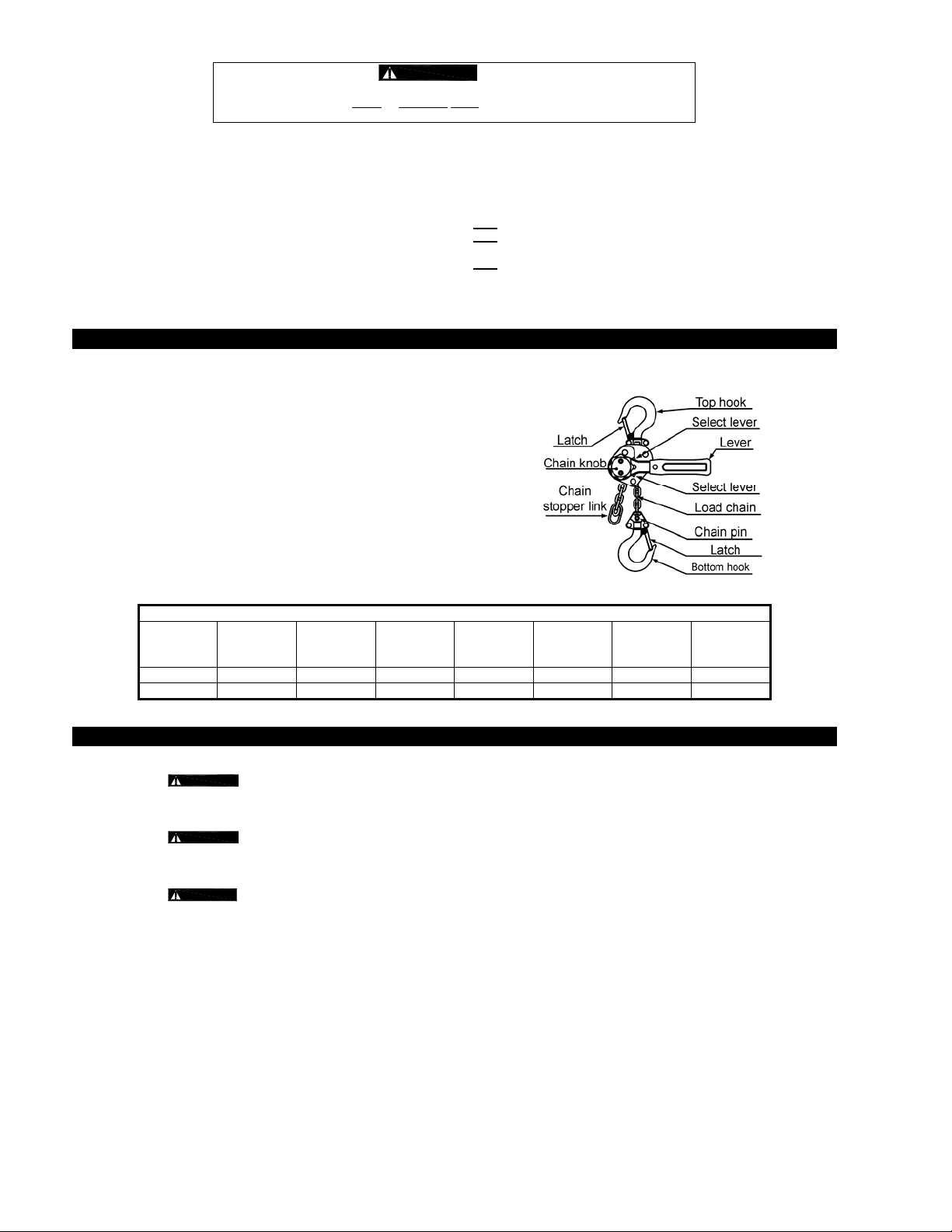
2.2.4 Hoist Parts
Pull to Lift
Rated Load
(lbs)
Load Chain
Dia. x Pitch
(mm)
Chain Fall
Lines
Net Weight
(lbs)
3.0 Operati on
3.1 Introduction
3.1.1
WARNINGS CONTAINED IN THIS MANUAL, INSTRUCTION AND WARNING LABELS ON THE HOIST OR LIFTING
SYSTEM, AND THE OPERATION SECTI O NS O F ANSI/ASME B30.21 and ANSI/ASME B30 . 10 .
3.1.2 Measure and record the “k” dimension of the top and bottom hook. See Table 4-3 under Section 4, “Inspection”.
3.1.3
and slippage can occur.
3.2 Free Chaining
3.2.1
Do not pull the no-load-side chain with the select lever set in the lowering (‘DN’) position. This will cause the lever to rotate,
3.2.2 Free Chain Principle
Free chaining allows the load chain to be moved freely because the brake is released under no load situations.
An internal spring releases the mechanical brake allowing the load chain to be pulled in either direction to the desired
The brake is engaged during lowering or lifting the load.
WARNING
WARNING
DANGER
Do not operate the hoist in free chain mode while a load is applied to the hoist.
Set the select lever to the lifting (‘UP’) position before performing a lifting operation. Do not leave the lever in the neutral
(‘N’) position.
which can be hazardous.
length.
HOIST OPERATORS SHALL BE REQUIRED TO READ THE OPERATION SECTION OF THIS MANUAL, THE
For the LX1A model hoist, lifting a light load (approx. 11 lbs. or less) may not produce full braking performance
Page 2 of 6
Page 3

3.2.3 How to Operate
3.2.4
DN
UP
N
CAUTION
Chain knob
Select lever
Lever
Do not pull the load chain suddenly in free chaining mode. Excessive pulling may set the brake and not allow the
1. Move the select lever to the neutral (‘N’) position as shown in the left picture.
2. With the no-load side chain pulled lightly, turn the chain knob counterclockwise.
3. In this mode, the load chain can be pulled through the hoist to its required length.
If the hoist does not shift into free chaining mode, hold the no-load-side chain and make
some lowering operations to release the brake.
chain to be moved. If this occurs the hoist must be reset.
3.2.5 Free chaining with the chain knob on the top as shown in Figure 3.1 may cause a braking force. In this case, direct the top of the knob
towards the horizontal side as shown in Figure 3.2 in free-chaining mode.
Figure 3-1
Figure 3-2
3.2.6 To reset the hoist for load operation, set the select lever to the lifting (‘UP’) or the lowering (‘DN’) position to eliminate the clearance
to the friction plate and operate the lever.
3.3 Lifting and Lowering Operation
3.3.1
3.3.2
DANGER
CAUTION
Do not operate the chain knob in lifting or lowering.
Before operating, make sure that the hoist is not in free chaining mode and set the select lever to the direction of load
movement desired, then ratchet the lever back and forth.
3.3.3 The following table shows select lever position and lever operation for lifting and lowering.
Table 3-1 Hoist Lever Operation
Select Lever Position Lever Rotation Load Movement
UP Clockwise Lift
DN Counterclockwise Lower
3.3.4
CAUTION
Under no-load or light load (approx. 6 ½ lbs.) conditions, if the load chain does not move, operate the lever while pulling slightly on
the load-side of the load chain. (Normal Operation)
If a lifting operation does not produce clicking sounds, the brake is released. Perform the lifting operation again with the load-side
chain pulled firmly until clicking sounds are heard.
4.0 Inspection
4.1 Initial Inspection – prior to initial use, all new, altered, or modified hoists shall be inspected by a designated person to ensure
compliance with the applicable provisions of this manual.
4.2 Inspection Classification – The inspection procedure herein is based on ANSI/ASME B30.21. Inspections for hoists in regular
service are divided into FREQUENT and PERIODIC groups based upon the intervals at which inspection should be performed. The
intervals in turn are dependent upon the degree of service and usage the hoists are subjected to. FREQUENT intervals range from
monthly to daily and PERIODIC intervals range from quarterly to yearly. Consult Harrington or ANSI/ASME B30.21 for the exact
interval criteria.
4.3 Frequent Inspection
4.3.1 Inspections should be made on a FREQUENT basis in accordance with Table 4-1, “Frequent Inspection.” Included in these
FREQUENT Inspections are observations made during operation for any defects or damage that might appear between Periodic
Inspections. Evaluation and resolution of the results of FREQUENT Inspections shall be made by a designated person such
that the hoist is maintained in safe working condition.
Table 4-1 Frequent Inspection
All functional operating mechanisms for proper operation and adjustment, m aladjustment and unusual soun ds.
Hoist braking system for proper operation
Hooks and latches in accordance with ANSI/ASME B30.10
Hook latch operation
Load chain in accordance with Section 4.5
Hoist lever for bends, cracks, etc,
Hoist support for damage
Page 3 of 6
Page 4

4.4 Periodic Inspection
4.4.1 Inspections should be made on a PERIODIC basis in accordance with Table 4-2, “Periodic Inspection.” Evaluation and
resolution of the results of PERIODIC Inspections shall be made by a designated person such that the hoist is maintained in
safe working condition.
4.4.2 For inspections where load suspension parts of the hoist are disassembled, a load test per ANSI/ASME B30.21 must be
performed on the hoist after it is re-assembled and prior to its return to service.
Table 4-2 Periodic Inspection
Requirements of frequent inspection.
Evidence of loose bolts, nuts, or rivets.
Evidence of worn, corroded, cracked, or distorted parts such as suspension housing, chain attachments, yokes,
suspension bolts, shafts, gears, bearings, pins, rollers and locking and clamping devices.
Evidence of damage to hook retaining nuts or collars and pins, and welds or rivets used to secure the retaining membe rs.
Evidence of damage or excessive wear of load sheave.
Evidence of worn, glazed or oil contaminated friction disks; worn pawls, cams or ratchet; co rroded, stretched, or broken paw l
springs in brake mechanism.
Evidence of damage to supporting structure.
Function label on hoist for legibility.
Warning label properly attached to the hoist and legible (see Section 7, Fig. No. 37).
End connections of load chain stopper link.
4.5 Inspection Methods and Criteria
4.5.1 This section covers the inspection of specific items. The list of items in this section is based on those listed in ANSI/ASME
B30.21 for the Frequent and Periodic Inspection.
4.5.2 Frequent Inspection - Not intended to involve disassembly of the hoist. Disassembly for further inspection would be required
if only if frequent inspection results so indicate. Disassembly and further inspection should only be performed by a qualified
person trained in the disassembly and re-assembly of the hoist.
4.5.3 Periodic Inspection - Disassembly of the hoist is required. Disassembly should only be performed by a qualified person
trained in the disassembly and re-assembly of the hoist.
Table 4-3 Hoist Inspection Methods and Criteria
Item Method Criteria Action
Functional
operating
mechanisms.
Braking System
– Components
Braking System
– Friction Plate
Housing
Mechanical and
Lifting System –
Components
Hooks –
Condition
Hooks – Fretting
wear
Hooks – Stretch Measure The "k" dimension should not be greater than 1.05 times that measured and
Hooks – Hook
Latches
Hooks – Yoke
Assembly
Yoke – Hole
Deformation
Chain Pin & Top
Pin – Deformation
Load Chain –
Surface
Condition,
Lubrication
Load Chain –
Pitch and Wire
Diameter
Visual, Auditory Mechanisms should be properly adjusted and should not produce unusual sounds
Visual Brake Pawl, Pawl Shaft, Pawl Spring, Friction Disc and Ratchet Disc should not
Visual, Measure The surface of the friction plate should be free of grease, oil, scars, gouges and
Visual, Auditory,
Function
Visual Should be free of gouges, dents, weld splatter, significant corrosion, twists,
Measure The "u" and "t" dimensions should not be less than the discard value listed in
Visual, Function Latch should not be deformed. Attachment of latch to hook should not be loose
Visual Should be free of significant rust, weld splatter, nicks, gouges. Holes should not
Visual, Measure The "d" dimension of the chain pin hole and "D" dimension of the top pin hole
Visual, Measure The chain pin and top pin should be free of scars or significant deformation. The
Visual Should be free of gouges, nicks, dents, weld splatter and corrosion. Links should
Measure The "P" dimension should not be greater than discard value listed in Table 4-5.
when operated. Components should not be deformed, scarred or show significant
wear.
be deformed scarred or show significant wear.
wear and have uniform thickness. The thickness of both plates together should
not be less than the di scard value listed in Table 4-6.
Hoist components including load blocks, suspension housing, chain attachments,
clevises, yokes, suspension bolts, shafts, gears, bear ings, pins and rollers should
be free of cracks, distortion, significant wear and corrosion. Evidence of same
can be detected visually or via detection of unusual sounds during operation.
deformations, significant wear, dirt and grime. Hook should swivel freely.
Table 4-4.
recorded at the time of purchase (See Section 3.1). If recorded "k" values are not
available for hooks when new, use nominal "k" values from Table 4-4.
or stiff. Latch spring should not be missing and should not be weak.
be elongated, fasteners should not be loose (Refer to figure in Section 7.0), and
there should be no gap between mating parts.
should not be greater than the discard value listed in Table 4-7.
"d" and "D" dimension should not be less than discard value listed in Table 4-8.
not be deformed, and should not show signs of abrasion. Surfaces where links
bear on one another should be free of significant wear. Entire surface should be
coated with lubricant and should be free of dirt and grime.
The "d" dimension should not be less than discard value listed in Table 4-5.
Repair or replace
as required.
Replace
Replace
Replace.
Replace.
Replace.
Replace.
Replace.
Torque or
replace as
required.
Replace Hook
Set
Replace
Replace (only
with load chain
listed in parts
list).
Replace (see
above). Inspect
load sheave.
Page 4 of 6
Page 5

Table 4-3 Hoist Inspection Methods and Criteria – Continued
Item Method Criteria Action
Bolts, Nuts and
Rivets
Visual, Check
with Proper Tool
Bolts, nuts and rivets should not be loose, deformed or corroded. Tighten or replace
as required.
Load Sheave Visual Pockets of Load Sheave should be clean and free of significant wear. Replace.
Warning Labels Visual Warning Labels should be affixed to the hoist and they should be legible. (see
Replace.
Section 7, Figure Number 37)
Hoist Capacity
Label
Visual The label that indicates the capacity of the hoist should be legible and securely
attached to the hoist.
Replace.
Table 4-4 Top Hook & Bottom Hook Dimensions
“k” Measured When New:
___________________
Top:
Bottom:
_________________
"u" Dimension
inch (mm)
Standard Discard Standard Discard
Product Code
Nominal "k"
Dimension*
inch (mm)
LX003 1.35 (34.4) 0.49 (12.5) 0.47 (11.9) 0.43 (11.0) 0.41 (10.5)
"t" Dimension
inch (mm)
LX005 1.67 (42.5) 0.59 (15.0) 0.56 (14.3) 0.47 (12.0) 0.45 (11.4)
* These values are nominal since the dimension is not controlled to a tolerance. The "k" dimension should be measured when the hook is
new - this becomes a reference measurement. Subsequent measurements are compared to this reference to make determinations about
hook deformation/stretch. See Section 4-5, “Hooks - Stretch”.
Table 4-5 Chain Wear Dimensions
Product
Code
"P" inch (mm) "d" inch (mm)
Standard Discard Standard Discard
LX003 1.79 (45.5) 1.84 (46.8) 0.126 (3.2) 0.11 (2.9)
LX005 2.38 (60.5) 2.45 (62.5) 0.169 (4.3) 0.15 (3.9)
Table 4-6 Friction Plate Dimensions
Product
Code
LX003
LX005
Standard
inch (mm)
Discard
inch (mm)
0.20 (5.0) 0.18 (4.5)
Table 4-7 Yoke Hole Chain Pin and Top Pin Dimensions
Product Code
Chain Pin Hole "d"
inch (mm)
Standard Discard Standard Discard
Top Pin Hole, "D"
inch (mm)
LX003 0.33 (8.3) 0.35 (8.8)
LX005 0.20 (5.2) 0.22 (5.7) 0.41 (10.3) 4.25 (10.8)
Table 4-8 Chain Pin and Top Pin Dimensions
Chain Pin Hole "d"
Product Code
LX003 0.33 (8.3) 0.35 (8.8)
inch (mm)
Standard Discard Standard Discard
Top Pin Hole, "D"
inch (mm)
LX005 0.20 (5.2) 0.22 (5.7) 0.41 (10.3) 4.25 (10.8)
5.0 Maintenance
5.1 For hoist maintenance or storage, comply with the following points.
5.1.1
5.1.2
DANGER
CAUTION
Do not lubricate the friction plate of the mechanical brake.
Always ensure that lubricant is applied to the load chain, the chain pin, the top pin, the hook necks, the hook latches and
the select lever. Refer to Section 2.2.2 “Hoist Parts”.
Do not store the hoist under a load.
Remove any dirt or water on the hoist.
Store the hoist in a dry and clean area.
Perform all inspections given in “4.0 Inspection” if irregularity of the hoist is found after operation.
Page 5 of 6
Page 6

6.0 Warranty
All products sold by Harrington Hoists, Inc. are warranted to be free from defects in material and workmanship from date of shipment by Harrington for the following periods:
Air and Electric Powered Hoists, Trolleys, and Crane Components - 1 year
The product must be used in accordance with manufacturer’s recommendations and must n ot have been subject to abuse, lack of maintenance, misuse, negligence, or
unauthorized repairs or alterations.
Should any defect in material or workmanship occur during the above time period in any product, as determined by Harrington Hoist’s inspection of the product, Harrington Hoists,
Inc. agrees, at its discretion, either to replace (not including installation) or repair the p art or product free of charge and deliver said item F.O.B. Harrington Hoists, Inc. place of
business to customer.
Customer must obtain a Return Goods Authorization as directe d by Harrington or Harrington’s published repair center prior to ship ping product for warranty evaluation. An
explanation of the complaint must accompany the product. Product must be returned fre ight prepaid. Upon repair, the product will be covered for the remainder of the origin al
warranty period. If it is determined there is no defect, or that the defect resulted from causes not within the scope of Harrington’s warranty, the customer will be responsible for the
costs of returning the product.
Harrington Hoists, Inc. disclaims any and all other warranties of any kind expressed or implied as to the product’s merchantability or fitness for a particular application. Harrington
will not be liable for death, injuries to persons or property or for incidenta l, contingent, special or consequential damages, loss or expense arising in connection with the use or
inability whatever, regardless of whether damage, loss or expense results from any act or failure to act by Harrington, whether negligent or willful, or from any other reason.
7.0 Parts List
Manual Hoists & Trolleys - 2 years
Spare / Replacement Parts - 1 year
LX003 Bottom Hook:
*
• Refer to section 2.2.2 For
technical information.
• Fastener Assembly:
– Torque to 40 – 48 lb
– Use Loctite® Threadlocker
241 or 242.
**
Pawl Spring Assembly = 2 springs.
Figure
Part Name
No.
1 Top Hook Assembly
2 Latch Assembly
Bottom Hook Assembly
3 *
4 Latch Assembly
4a Spring Washer
4b Hex Nut
4c Socket Head Cap Screw
5 Load Chain
6 Chain Pin
7 Chain Stopper Link
8 Slotted Nut
9 Split Pin
10 Frame A
11 Frame B
12 Gear Case with Nameplate
14 Stud A
15 Stud B
16 Pinion
17 Load Gear
18 Load Sheave
19 Friction Plate
20 Ratchet Disc
21 Friction Disc
Model
LX1A
L1XB
Parts
Per
Hoist
LX003
1/4 Ton
1 L1XA0031001 L1XA0051001
1 L1XA0031071 L1XA0051071
1 L1XA0031021 L1XA0051021
1 L1XA0031071 L1XA0051071
2 9012707
2 9093414
2 9091203
FT LCLX003NP LCLX005NP
1 L1LA0059041
1 L1XA0039045 L1LA0059045
1 L1LA0059049
1 9009401
1 L1XA0039101 L1XA0059101
1 L1XA0039102 L1XA0059102
1 L1XA0035103 L1XA0055103
2 L1XA0039104 L1XA0059104
1 L1XA0039105 L1XA0059105
1 L1XA0039111 L1XA0059111
1 L1XA0039111R3 L1XA0059111R2
1 L1XA0039114 L1XA0059114
1 L1XA0039116 L1XA0059116
2 L1XA0039151 L1XA0059151
1 L1XA0039152 L1XA0059152
1 L1XA0039153 L1XA0059153
1/2 Ton
LX005
Figure
Part Name
No.
22 Pawl
23 Pawl Spring Assembly **
24 Guide Roller
25 Stripper
26 Top Pin
27 Brake Cover
28 Button Head Socket Screw
29 Button Head Socket Screw
30
Internal Tooth Lock Washer
31 Chain Knob
32 Lever Clamping Plate
33 Socket Bolt
34 Conical Lock Washer
35 Free Chain Spring
36 Lever Assembly
37 Warning Tag
38 Free Chain Plate
39 Cam Guide
Harrington Hoists, Inc.
Parts
Per
Model
Hoist
LX1A
LX1B
LX1A
L1XB
LX1A
LX1B
LX1A
L1XB
LX1A
LX1B
LX1A
LX1B
LX1B
LX1B
Harrington Hoists - Western Division
LX003
1/4 Ton
1 L1XA0039155
1 L1XA0031158
1 L1XA0039161 L1XA0059161
1 L1XA0039162 L1XA0059162
1 L1XA0039163 L1XA0059163
1 L1XA0039172 L1XA0059172
2 L1XA0039173 L1XA0039174
1 L1XA0039174 L1XA0059174
3 96797J09
1 L1XA0039201R1 L1XA0059201R1
1 L1XA0039201R2
1 L1XA0039202R1 L1XA0059202R1
1 L1XA0039202R2 L1XA0059202R2
2 9091224 9091225
1 9091201
2 L1XA0039204R1
1 L1XA0039204R2
1 L1XA0039205 L1XA0059205
1 L1XA0039205R3
1 L1XA0034211 L1XA0054211
1 L1XA0034211R2 L1XA0054211R2
1 WTAG9
1 L1XA0039209
1 L1XA0039203
LX005
1/2 Ton
401 West End Avenue 2341 Pomona Rincon Rd. #103
Manheim, PA 17545 Corona, CA 91720
Phone: 717-665-2000 Phone: 951-279-7100
Toll Free: 800-233-3010 Toll Free: 800-317-7111
Fax: 717-665-2861 Fax: 951-279-7500
www.harringtonhoists.com
LXOM
- in.
f
Page 6 of 6
 Loading...