

Page 1
EFFECTIVE: February 2, 2004
r
y
y
Owner's Manual
SUPPLEMENT
ELECTRIC
CHAIN HOIST
ER and NER
SERIES
8 Ton through 20 Ton Capacity
4.7 HP MOTOR VERSION
Code, Lot and Serial Number
WARNING
This equipment should not be installed, operated o
maintained by any person who has not read and understood
all the contents of this manual. Failure to read and compl
with the contents of this manual can result in serious bodil
injury or death, and/or property damage.
Page 2

IMPORTANT INFORMATION ON HOW TO USE THIS MANUAL
This OWNER’S MANUAL SUPPLEMENT is intended for use in combination with the “Owner’s Manual for
Electric Chain Hoist ER and NER Series 1/8 through 5 Ton Capacity”. Refer to the Table of Contents below to
determine the location(s) of information pertaining to your hoist. References to the “Owner’s Manual for Electric Chain
Hoist ER and NER Series 1/8 through 5 Ton Capacity” will be designated by the use of the acronym “EROM”.
Table of Contents
Section Page Number/Location
1.0 Important Information and Warnings……...………………...………………………………………. EROM
1.1 Terms and Summary EROM
1.2 Warning Tags and Labels EROM
2.0 Technical Information………………………………………………………………………….…..………...4
2.1 Specifications 4
2.2 Dimensions 5
3.0 Preoperational Procedures …………………………………………………………………………………6
3.1 Fill Gear Box with Oil 6
3.2 Chain 6
3.3 Mounting Location 8
3.4 Mounting the Hoist 9
3.5 Electrical Connections 9
3.6 Preoperational Checks and Trial Operation 12
4.0 Operation…………………………………………………………………………………………..….. EROM
4.1 Introduction EROM
4.2 Shall’s and Shall Not’s for Operation EROM
4.3 Hoist Controls EROM
2
Page 3

Section Page Number/Location
5.0 Inspection……………………………….………………………………….…………..…….. 13 and EROM
5.1 General EROM
5.2 Inspection Classification EROM
5.3 Frequent Inspection EROM
5.4 Periodic Inspection EROM
5.5 Occasionally Used Hoists EROM
5.6 Inspection Records EROM
5.7 Inspection Methods and Criteria 13 and EROM
6.0 Maintenance & Handling……………………………………………………….…………….16 and EROM
6.1 Count/Hour Meter EROM
6.2 Lubrication 16 and EROM
6.3 Motor Brake 16 and EROM
6.4 Load Chain 16 and EROM
6.5 Friction Clutch and Mechanical Load Brake with Friction Clutch EROM
6.6 Storage EROM
6.7 Outdoor Installation EROM
7.0 Troubleshooting ………………………………………………………………………………….……EROM
8.0 Material Safety Data Sheets……………………………………..……..…….………………………EROM
8.1 ER Model Gear Box Oil EROM
8.2 ER Model Load Chain Grease EROM
9.0 Warranty………………………………………………………………………………………………. EROM
10.0 Parts List……………………………………………………………………………………………………. 20
3
Page 4
2.0 Technical Information
2.1 Specifications
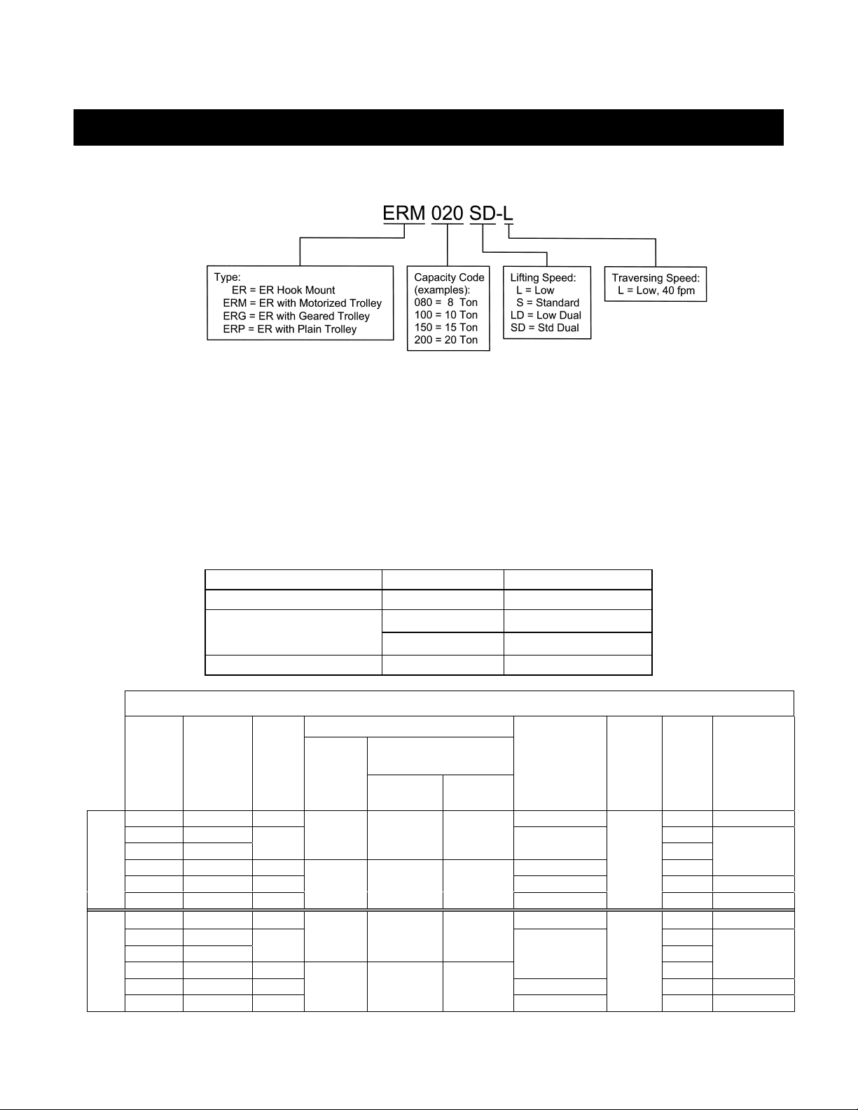
2.1.1 Product Code
2.1.2 8 through 20 ton hoists are available in one standard specification:
• Dual Speed Motor
• Mechanical Load Brake/Friction Clutch Combination
• Count/Hour Meter
• Upper/Lower Limit Switch
2.1.3 Operating Conditions and Environment
Temperature range: -4° to +104°F (-20° to +40°C)
Relative Humidity: 85% or less
Enclosure Rating: Hoist Meets IP 55, Pendant Meets IP65
Supply Voltage: Standard 208-230/460V-3-60, Optional 575V-3-60, Special Voltages Available
Hoist Speed: Single Dual
ASME Duty Classification: H4 H4
Intermittent Duty Rating:
60% ED 40%/20% ED
360 starts/hour 120/240 starts/hour
Short Time Duty Rating: 60 min. 30/10 min.
Table 2-1 Hoist Specifications
Motor
Capacity
(Ton)
8 ER080S 8 11.2 x 3 439 5.9
10 ER100L 597
10 ER100L-LG
10 ER100S 12 11.2 x 4 683
15 ER150S 8 11.2 x 6 897 12.1
Single Speed
20 ER200S 6
8 ER080SD 8/3 11.2 x 3 485 5.9
10 ER100LD 642
10 ER100LD-LG
10 ER100SD 12/4
15 ER150SD 8/3 11.2 x 6 985 12.1
Dual Speed
20 ER200SD 6/2
Product
Code
Lifting
Speed
(ft/min)
6
6/2
Output
(hp)
4.7 18.3 9.2
4.7 x 2 18.3 x 2 9.2 x 2
4.7/1.6 19.6/9.4 9.8/4.7
4.7/1.6x2 19.6/9.4 x 2 9.8/4.7 x 2
Current Draw
(amps)
208V or
230V
460V
Load Chain
Wire Diameter
(mm) x Chain
Fall Lines
11.2 x 4
11.2 x 8
11.2 x 4
11.2 x 8
Load
Sheave
Pockets
4
4
Weight
(lbs.)
1065 16.1
1153 16.1
Net
496
542
772
Weight for
One Addnl.
FT. of Lift
(lbs.)
8.1
8.1
4
Page 5
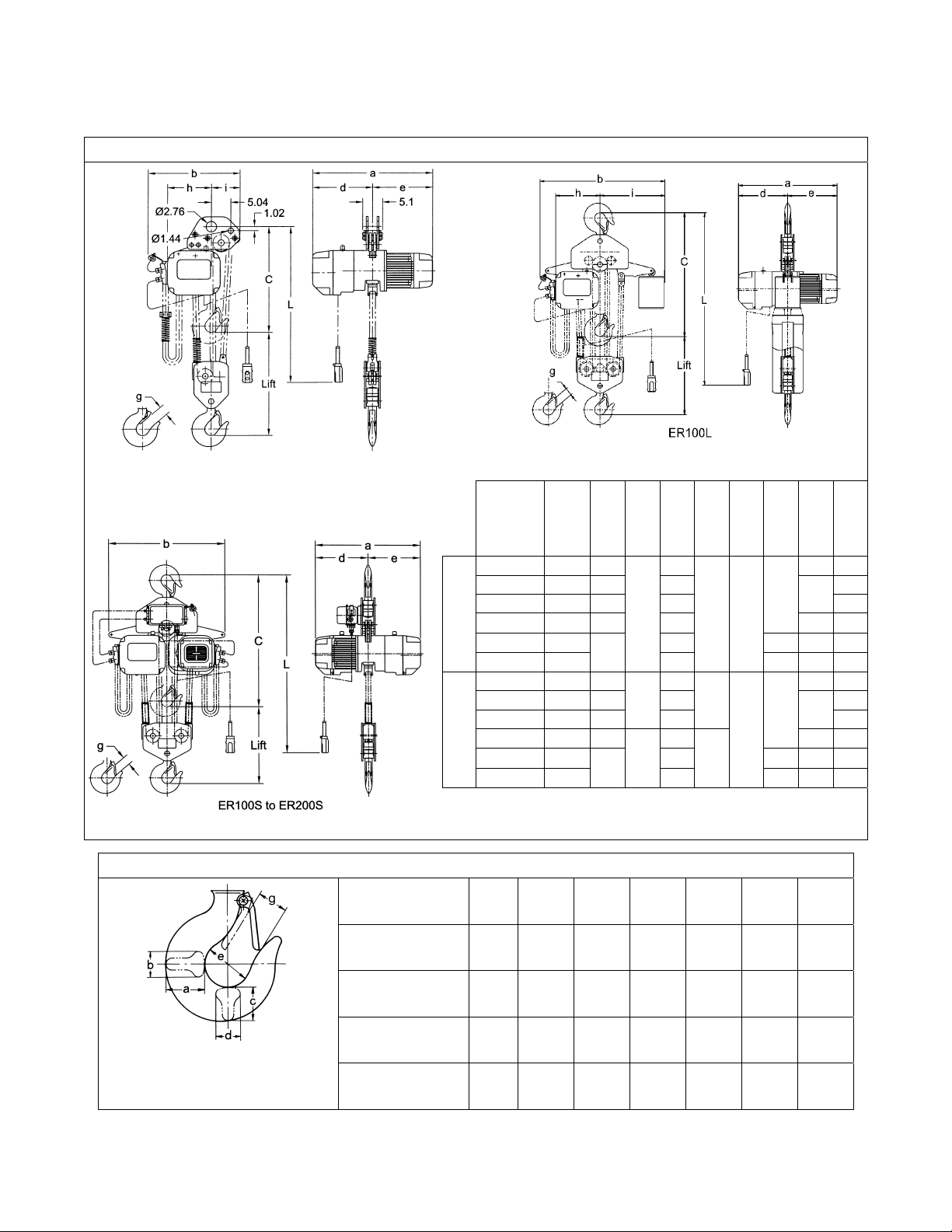
2.2 Dimensions
ER080S
Table 2-2 Hoist Dimensions
Head-
Product
Code
ER080S ~ 42.0 8.7 23.8 11.3 7.5
ER100L 52.6 9.2 39.4 20.4
ER100L-LG
ER100S 52.6 9.2 34.2
ER150S 60.6 41.3 3.1
SINGLE SPEED
ER200S 65.0
ER080SD ~ 42.0 8.7 23.8 11.3 7.5
ER100LD 52.6 9.2 39.4 20.4
ER100LD-LG
ER100SD 52.6 9.2 34.2
DUAL
SPEED
ER150SD 60.6 41.3 3.1
ER200SD 65.0
*The "L" dimensions are based on the standard lift of 10 feet.
~Hoist available lug mount only. Dimension C (headroom) and L are to the
center of the lug hole.
room:
(in)
39.7 8.7 28.0
39.7 8.7
L*
C
(ft)a(in)b(in)d(in)e(in)g(in)h(in)i(in)
30.9
10.5
32.2
33.5
10.5
49.1
28.0
49.1
15.5 15.5
16.8
15.5
16.8
2.4
3.4
2.4
3.4
14.0
8.9
14.0
8.9
Table 2-3 Hook Dimensions*
Capacity Code
080S
100L, 100S T & B 3.3 2.2 2.9 1.9 3.3 2.4
150S
T = Top Hook
B = Bottom Hook
Units = in.
*Refer to EROM Section 5.7 for inspection dimensions and limits.
200S
Hookabcdeg
B 3.3 2.2 2.9 1.9 3.3 2.4
T & B 4.1 2.8 3.4 2.4 3.9 3.1
T & B 4.6 3.3 3.9 2.8 4.3 3.4
5
Page 6
3.0 Preoperational Procedures
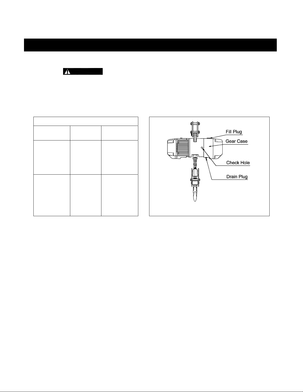
3.1 Fill Gear Box with Oil
3.1.1
3.1.2 For a new hoist the correct quantity and type of oil is supplied with the hoist in separate containers.
3.1.3 Refer to Section 6.2 of the EROM when replacing the gear oil or checking the gear oil level.
Table 3-1 Amount of Gear Oil
Capacity
Code
080S, 100L 3.17 3.0
100S, 150S,
200S
CAUTION
Remove the fill plug from the top of the hoist and connect the flexible pour tube to the oil container.
Pour in all of the oil from the separate containers, then replace the fill plug.
Quarts Liters
6.34
(3.17 per
hoist body)
DO NOT use any oil or quantity other than that listed below.
6.0
(3.0 per
hoist body)
Figure 3-1 Oil Plug Locations
3.2 Chain
3.2.1 The quantity and location of the chain components including chain springs and stoppers depends on
3.2.2 When the hoist is used without a chain container, the free end of the chain is attached to the hoist body
ER Gear Oil:
§ Harrington standard: Antoil super B (NIPPON OIL)
§ Acceptable equivalent: Meropa No.68 (TEXACO)
the hoist model and capacity. Never operate the hoist with incorrect, missing or damaged chain
components. Refer to the hoist's nameplate, Table 3-2, and Figure 3-2 and ensure that all chain
components are in the correct location and properly installed.
as shown in Figure 3-2. Connect the “no load” end of the chain to Chain Guide A and the pre-installed
socket bolt and lock nut. Make sure the chain remains free of twists and the chain Stopper is installed
on the correct link. Refer to Table 3-2 for proper placement of Stopper.
6
Page 7
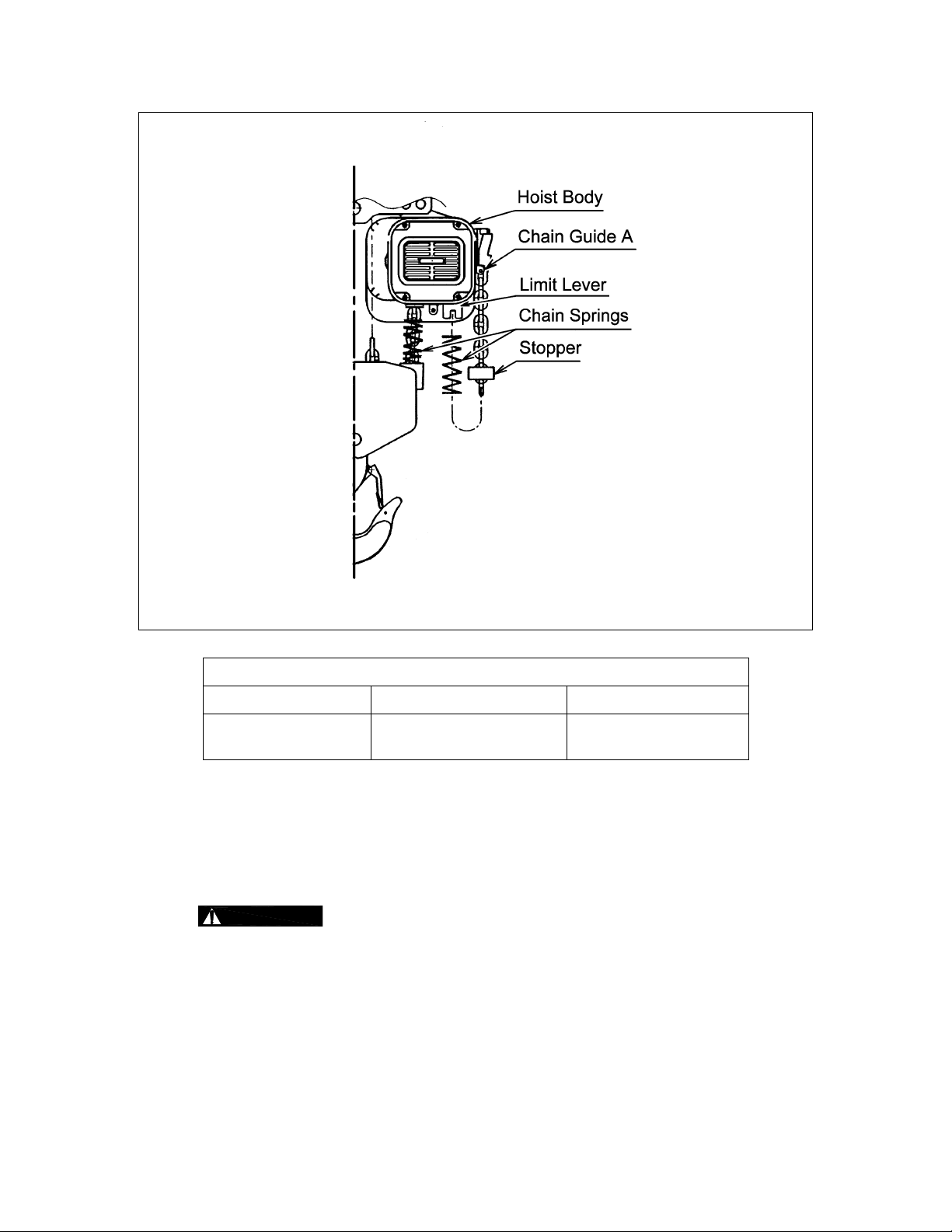
Figure 3-2 Chain Component Arrangement
Table 3-2 Chain Stopper Placement
Capacity Code Without Chain Container With Chain Container
080S, 100L, 100S,
150S, 200S
th
9
link from the free end 3rd link from the free end
3.2.3 When the optional canvas chain container(s) is used, unfold it fully and install it on the hoist body(ies)
as shown in Figure 3-3. In this case the free end of the chain is not attached to the hoist body and the
chain stopper is installed on the third link from the free end. To place the chain into the chain
container(s), feed the chain into the chain container(s) beginning with the free end. Take care to avoid
twisting or tangling the chain. NEVER put all the chain into the container(s) at once. Lumped or
twisted chain may activate the down limit switch and stop the hoist during lowering.
3.2.4
CAUTION
Each chain container indicates the maximum length of the load chain that can be
stored in the container. The amount of chain the container must hold is equal to the lift on the hoist.
DO NOT use a chain container with a storage capacity less than the lift length on the hoist. If all of the
chain can not be stored in the container, the limit switch will not operate properly.
7
Page 8
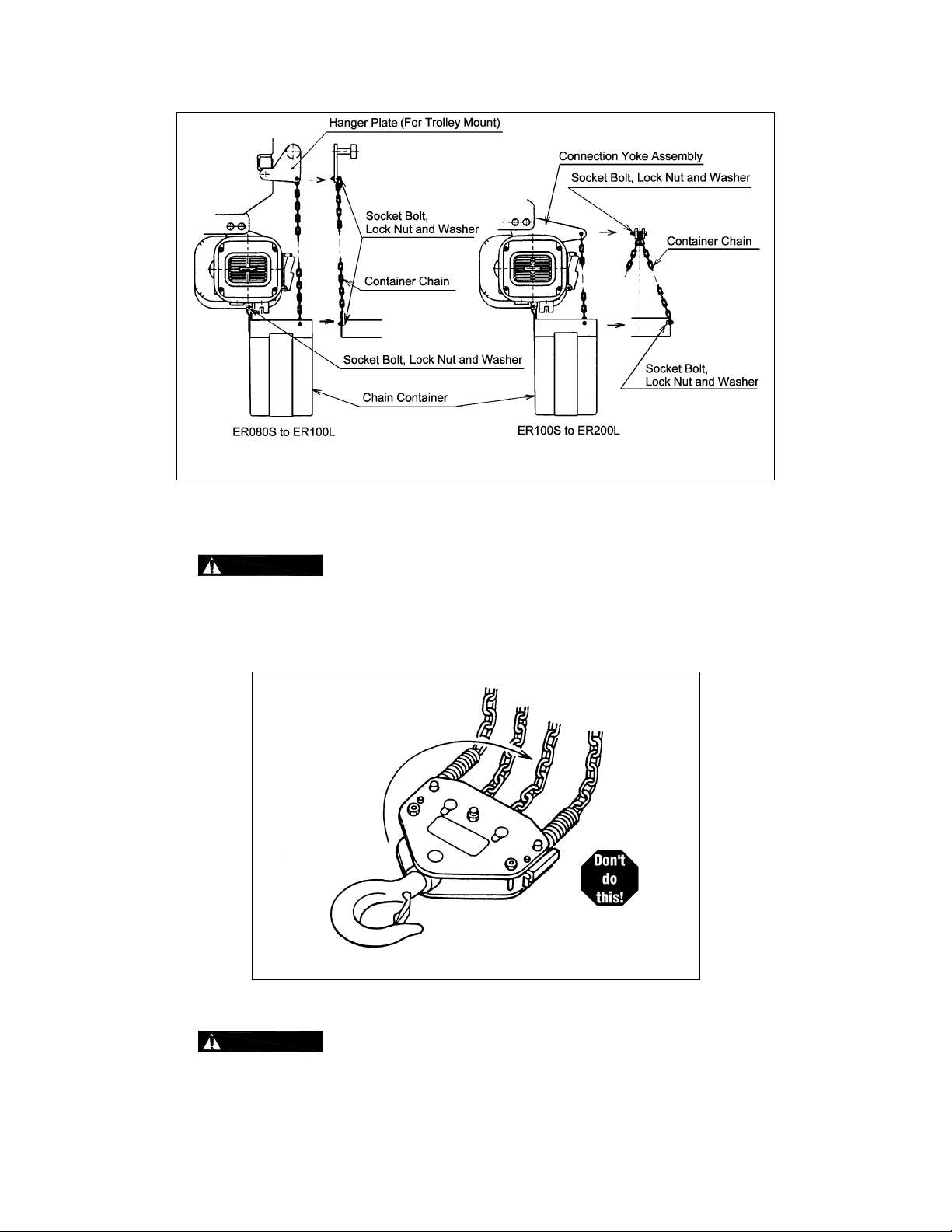
Figure 3-3 Installation of Chain Container
3.2.5 When using an optional steel chain container, refer to the instructions and/or assembly drawing(s)
provided with the container for correct assembly and attachment.
3.2.6
3.2.7 Lubricate the entire length of the load chain with the supplied tube(s) of grease per the instructions in
WARNING
Make sure the bottom hook is not capsized. See Figures 3-4. Correct all chain irregularities before
conducting the first hoist operation.
Section 6.2.1.
3.3 Mounting Location
Verify that the load chain is not twisted or tangled prior to operating the hoist.
Figure 3-4 Capsized Hook and Chain
3.3.1
WARNING
structure are adequate to support the hoist and its loads. If necessary consult a professional that is
qualified to evaluate the adequacy of the suspension location and its supporting structure.
Prior to mounting the hoist ensure that the suspension and the supporting
8
Page 9

3.3.2
NOTICE
3.4 Mounting the Hoist
3.4.1 Manual Trolley - Follow instructions in Owner’s Manual provided with the trolley.
3.4.2 Motorized Trolley - Follow instructions in Owner’s Manual provided with the trolley.
3.4.3 Hook Mounted to a Fixed Location - Attach the hoist’s top hook to the fixed suspension point.
3.4.4 Lug Mounted ER080S and ER100L-LG – To maintain proper balance when the hoist is not loaded, it
is necessary to install a stabilizing shaft to prevent the hoist from pivoting on the main support shaft.
Refer to Table 2-2 for the size and location of the main support and stablizing holes in the hoist’s top
suspension plates.
See Section 6.7 of the EROM for outdoor installation considerations.
3.4.5
WARNING
that the hook’s latch is engaged.
3.5 Electrical Connections
3.5.1
3.5.2
3.5.3 This instruction applies to installations where the hoist is installed hook mounted to a fixed suspension
CAUTION
DANGER
been de-energized (disconnected). Lock out and tag out in accordance with ANSI Z244.1 “Personnel
Protection -Lockout/Tagout of Energy Sources”.
point or installed on a manual trolley. In this case the hoist is controlled by a pendant with two push
buttons – one for raising and one for lowering. Refer to the appropriate trolley Owner’s Manual if the
hoist is installed on a motorized trolley.
Pendant Cord
The Pendant Cord connects to the hoist via a 5-pin (5P) Plug and Socket. Make this connection as
follows:
§ Refer to Figure 3-5 or 3-6 depending on the Product Code.
§ For ER080S and ER100L - Insert the 5P Plug into the 5P Socket on the hoist body and hand
tighten the Screw Coupling. Install the strain relief cable to the bottom of the hoist body.
§ For ER100S, ER150S and ER200S - Insert the 5P Plug into the 5P Socket on the switch box
and hand tighten the Screw Coupling. Install the strain relief cable onto the cord strain relief
stopper located at the 5P socket.
Ensure that the fixed suspension point rests on the center of the hook’s saddle and
Ensure that the voltage of the electric power supply is proper for the hoist or trolley.
Before proceeding, ensure that the electrical supply for the hoist or trolley has
Power Supply Cable - Hoist Connection
The Power Supply Cable connects to the hoist via a 4-pin (4P) plug and socket or a direct fitting
depending on the product code. Make this connection as follows:
§ Refer to Figure 3-5 or 3-6 depending on the product code.
§ For ER080S and ER100L insert the 4P plug of the Power Supply Cable into the 4P Socket on
the hoist and hand tighten the screw coupling.
§ For ER100S, ER150S, and ER200S – The power supply cable should be pre-installed to the
switch box and properly connected.
§ Install the Cable Support Arm (pre-installed on the Power Supply Cable) on to the Socket
Holder or Switch Box depending on the product code. Use the pre-installed Machine Screws
and Lock Washers.
§ Use care to avoid twisting or kinking the Power Supply Cable.
9
Page 10
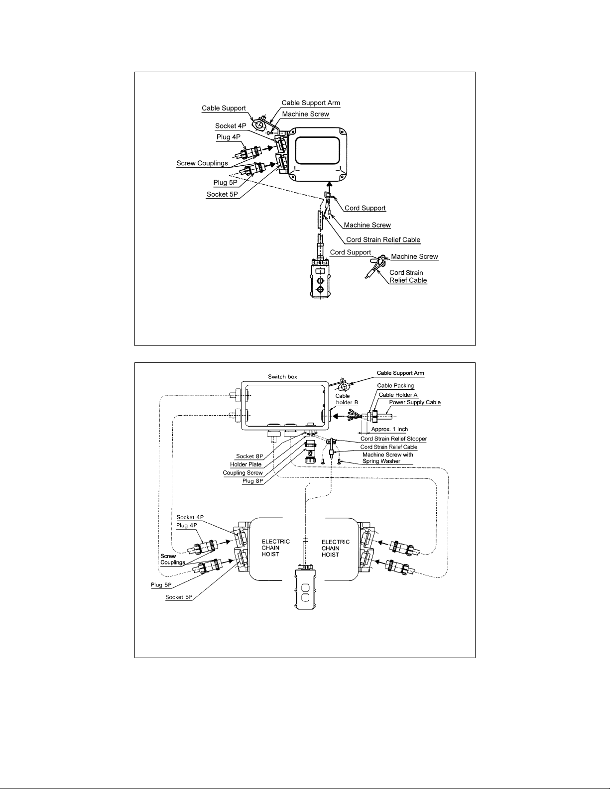
Figure 3-5 Pendant and Power Supply Cable Connections
for ER080S and ER100L
Figure 3-6 Pendant and Power Supply Cable Connections
for ER100S, ER150S and ER200S
10
Page 11
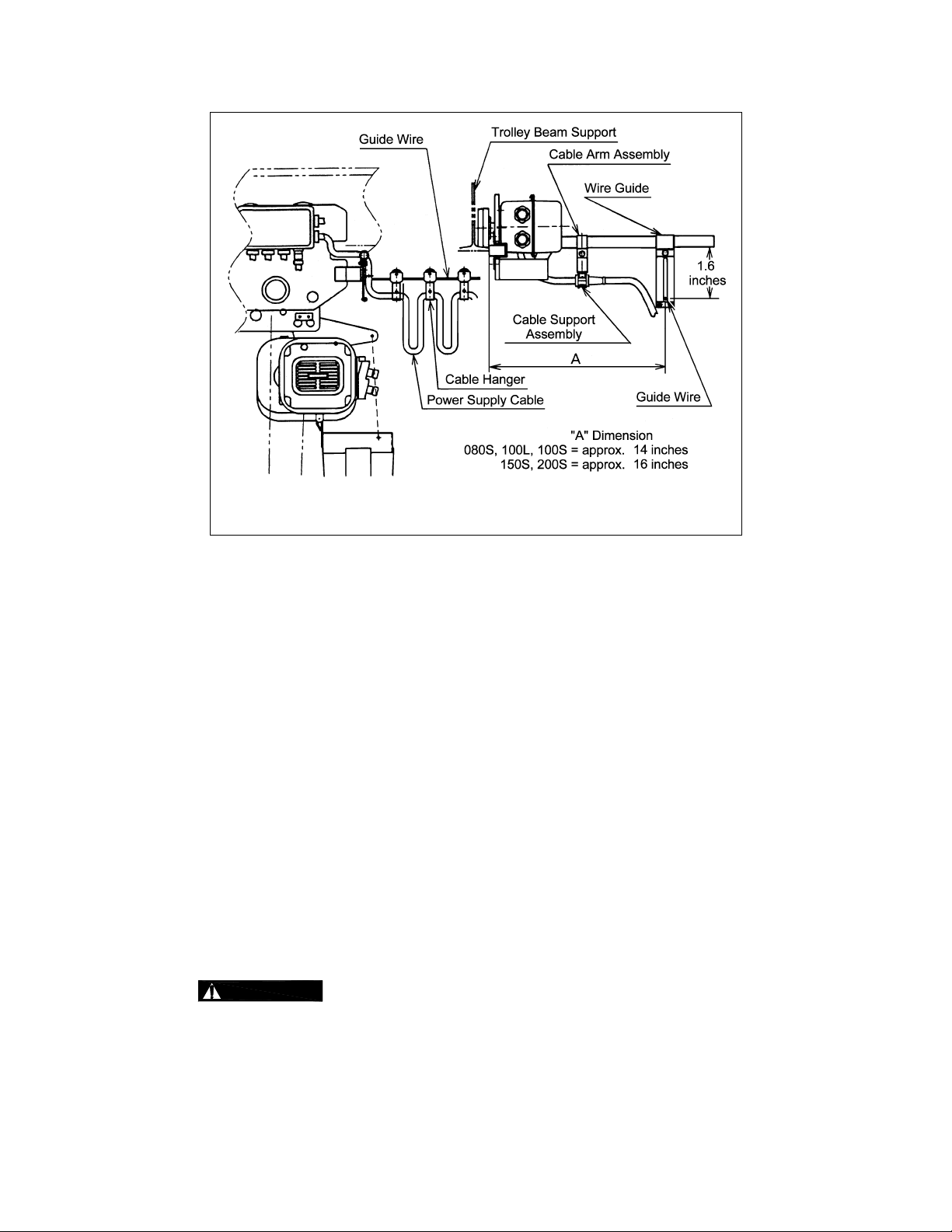
Figure 3-7 Power Supply Cable Festooning and Guide Wire Location
Power Supply Cable - Installation
If the hoist is hook mounted to a fixed support ensure that the Power Supply Cable is properly
installed and supported between the hoist and the electrical power supply.
If the hoist is installed on a manual trolley, then the Power Supply Cable must be installed along
the beam that the trolley runs on. For curved beams a special cable suspension system will be
needed, and this instruction does not apply. For straight beams install the Power Supply Cable as
follows:
§ Refer to Figure 3-7.
§ Install the Cable Hangers on to the Power Supply Cable spacing them every 5 feet.
§ Install a Guide Wire system parallel to the Bridge Beam. Pass the Guide Wire through the
Cable Hangers and the Wire Guide.
§ Make sure the Guide Wire is properly tensioned and the Power Supply Cable is not twisted or
kinked.
3.5.4 Connection to Electrical Power Source - The red, white, and black wires of the Power Supply Cable
should be connected to an Electric Power Disconnect Switch or Circuit Breaker. This connection
should be made so that the hoist is phased properly. Refer to Section 3.6.11 for instructions on how to
check for correct power supply phase connection.
3.5.5 Fuse/Breaker Capacity -The hoist's power supply should be equipped with overcurrent protection such
as fuses, which should be selected for 110% to 120% of total listed full load amperage, and should be
dual element time-delay fuses. Refer to the motor nameplate(s) for the full load amperage draw.
3.5.6
DANGER
shock hazard when touching any part of the hoist or trolley. In the Power Supply Cable the ground wire
will be either Green with Yellow stripe or solid Green. It should always be connected to a suitable
ground connection. Do not paint the trolley wheel running surfaces of the beam as this can affect
grounding.
Grounding - An improper or insufficient ground connection creates an electrical
11
Page 12

3.6 Preoperational Checks and Trial Operation
3.6.1 Refer to the hoist’s nameplate and record the hoist's Code, Lot and Serial Number in the space
provided on the cover of this manual.
3.6.2
3.6.3
3.6.4 Measure and record the “k” dimension of all hooks on hoist. See Table 5-4 under Section 5
3.6.5 Ensure that the hoist is properly installed to either a fixed point, or trolley, whichever applies.
3.6.6 If hoist is installed on a trolley, ensure that
3.6.7 Ensure that all nuts, bolts and split pins (cotter pins) are sufficiently fastened.
3.6.8 Pull down on the Pendant and ensure that the Cord Strain Relief Cable takes the force, not the
3.6.9
3.6.10 Confirm proper operation.
WARNING
other lifting attachments before use. Inspect all load suspension members for damage prior to use and
replace or repair all damaged parts.
WARNING
Section 3.2 of this manual.
“Inspection”, of this manual.
§ trolley is properly installed on the beam, and
§ stops for the trolley are correctly positioned and securely installed on the beam.
Pendant Cord.
CAUTION
the rated value, electrical devices may not function normally.
Confirm the adequacy of the rated capacity for all slings, chains, wire ropes and all
Verify and correct all chain irregularities prior to operating the hoist. Refer to
Check supply voltage before everyday use. If the voltage varies more than 10% of
§ Before operating read and become familiar with Section 4 – Operation in the EROM.
§ Before operating ensure that the hoist (and trolley) meets the Inspection, Testing and Maintenance
requirements of ANSI/ASME B30.16.
§ Before operating ensure that nothing will interfere with the full range of the hoist’s (and trolley’s)
operation.
3.6.11 Proceed with trial operation to confirm proper operation.
§ Verify that the controls agree with hoist direction. Make sure that depression of the up button lifts
the load chain and depression of the down button lowers the load chain hook. If the load chain
does not move in the correct direction when the push buttons are pushed, the power supply is
phased incorrectly. In this case, turn off the power source or breaker switch then reverse any two of
the three wires at the power source. The hook will then move in accordance with the directions of
the push button.
§ Perform inspections per Section 5.2, “Frequent Inspections” in the EROM.
12
Page 13

5.0 Inspection
NOTICE
Use this table in conjunction with Table 5-3 of the EROM. The entries in this table replace in their entirety
Item Method Criteria Action
Hooks - Fretting
wear
Hooks - Stretch Measure The "k" dimension should not be greater than
The information listed in this section is intended to supplement Section 5.7 of the EROM.
Table 5-3 Hoist Inspection Methods and Criteria
the corresponding entries in Table 5-3 of the EROM.
Measure The "u" and "t" dimensions should not be less
than discard value listed in Table 5-4
1.15 times that measured and recorded at the
time of purchase (See Section 3.6). If recorded
"k" values are not available for hooks when new,
use nominal "k" values from Table 5-4.
Replace.
Replace.
Load Chain - Pitch
and Wire Diameter
Load Chain –
Reeving and
Evening
Measure The "P" dimension should not be greater than
maximum value listed in Table 5-5. The "d"
dimension should not be less than minimum value
listed in Table 5-5.
Visual Chain should be reeved properly through Load
and Idle Sheaves - refer to Section 6.4. Chain,
Chain Springs, Stoppers, and Chain Pin should
be installed properly - refer to Section 3.2. For
double body hoists, chain should be evenly
distributed – equal length of chain in each chain
container or equal lengths of chain on no-load
side of each hoist body.
Replace. Inspect
Load and Idle
Sheaves.
Reeve/Install chain
properly.
Lower hook until
lower limit switch is
activated on both
hoist bodies.
13
Page 14
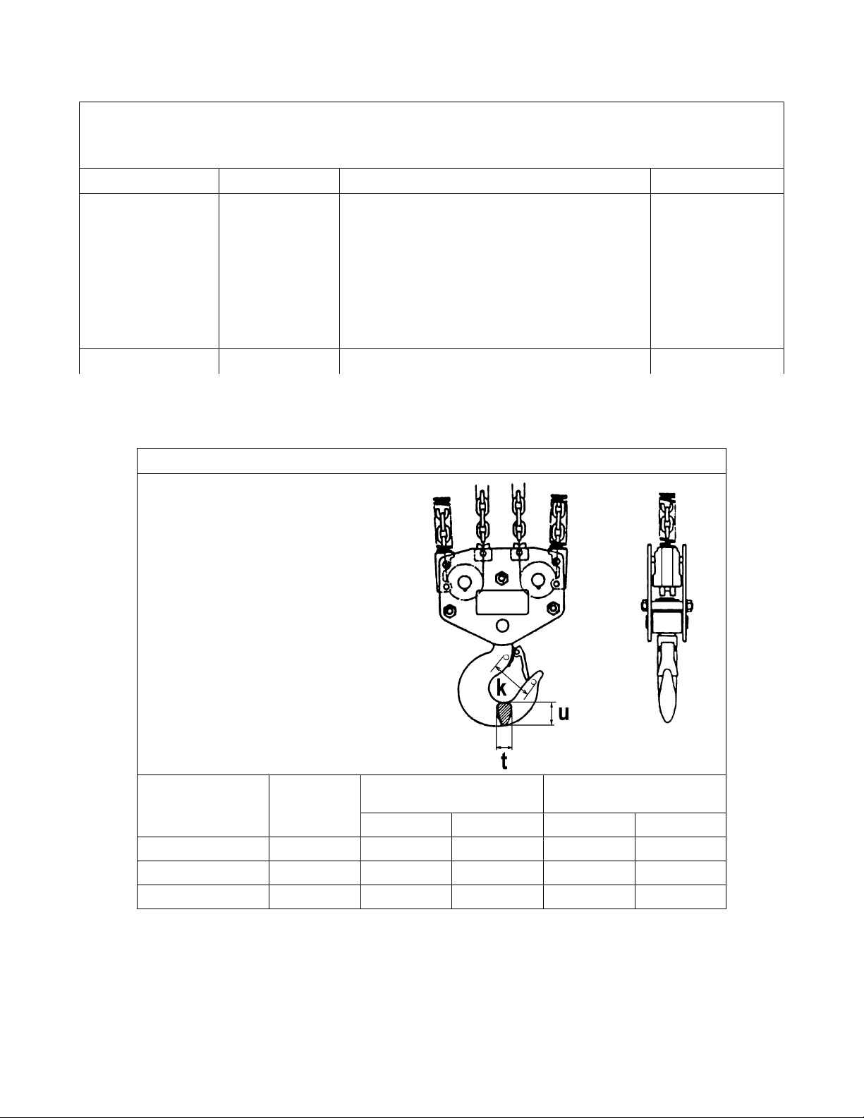
Table 5-3 Hoist Inspection Methods and Criteria
Use this table in conjunction with Table 5-3 of the EROM. The entries in this table replace in their entirety
the corresponding entries in Table 5-3 of the EROM.
Item Method Criteria Action
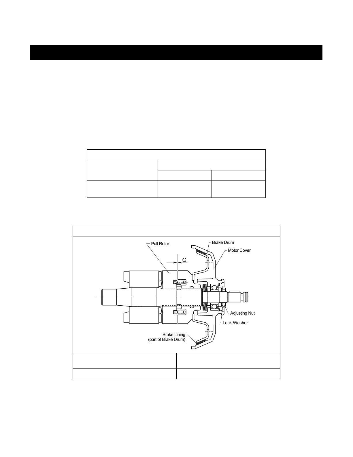
Motor Brake Measure, Visual Motor brake gap should be adjusted to the
distance shown in Table 6-3 before measuring
the brake wear. Brake lining dimension “A”
should not be less than discard value listed in
Table 5-6. Refer to Section 6.3 of the EROM for
gaining access to motor brake and for adjustment
and inspection procedures. Braking surfaces
should be clean, free of grease/oil and should not
be glazed.
Table 5-4 Top Hook & Bottom Hook Dimensions
“k” Measured When New:
Top: _________________________
Adjust, Repair or
Replace as
required.
Bottom: ______________________
Capacity Code
080S, 100L, 100S
150S
200S
Nominal "k"
Dimension*
inch (mm)
4.72(120) 2.87(73) 2.60(66) 1.89(48) 1.69(43)
5.04(128) 3.43(87) 3.07(78) 2.36(60) 2.13(54)
5.57(141.5) 3.92(99.5) 3.54(90) 2.76(70) 2.48(63)
"u" Dimension
inch (mm)
Standard Discard Standard Discard
"t" Dimension
inch (mm)
* These values are nominal since the dimension is not controlled to a tolerance. The "k"
dimension should be measured when the hook is new - this becomes a reference measurement.
Subsequent measurements are compared to this reference to make determinations about hook
deformation/stretch. See Section 5.7 of EROM, “Hooks - Stretch”.
14
Page 15
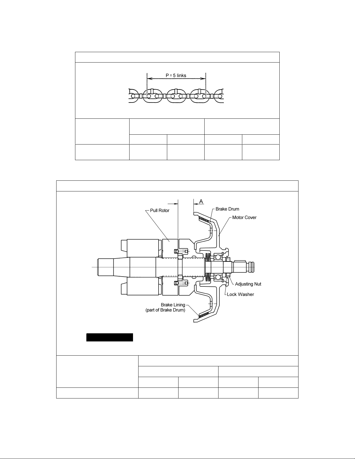
Table 5-5 Chain Wear Dimensions
Capacity Code
080S, 100L, 100S,
150S, 200S
“P” Dimension
inch (mm)
Standard Discard Standard Discard
6.75 (171.5) 6.85 (174.1) 0.44 (11.2) 0.40 (10.1)
“d” Dimension
inch (mm)
Table 5-6 Motor Brake Wear Dimensions
NOTICE
Capacity Code
080S, 100L, 100S, 150S, 200S
Brake must be properly adjusted before measuring "A".
See Section 6.3 of EROM
"A" Dimension - inch (mm)
Single Speed Dual Speed
Standard Discard Standard Discard
0.83 (21) 0.77 (19.5) 1.54 (39) 1.48 (37.5)
15
Page 16
6.0 Maintenance and Handling
6.2 Lubrication
6.2.1 Load Chain
§ Refer to 6.2.1 of the EROM.
6.2.2 Hooks and Suspension Components:
§ Refer to 6.2.2 of the EROM.
6.2.3 Gear Box:
§ Refer to 6.2.3 of the EROM except use the following table for checking oil level.
Table 6-3 Criteria for Checking Hoist Gear Oil Level
Capacity Code
080S, 100L, 100S, 0150S,
200S
Oil Level (Hoist at level position)
Min Max
1“ below bottom
edge of check hole
Even with bottom
edge of check hole.
6.3 Motor Brake - Use the table below in conjunction with Section 6.3 of the EROM. This table replaces
Table 6-3 of the EROM.
Table 6-3 Motor Brake Gap
6.4 Load Chain
6.4.1 Lubrication and Cleaning – refer to Section 6.2 of EROM.
6.4.2 Load Chain Replacement for ER080S and ER100L:
Capacity Code
080S, 100L, 100S, 150S, 200S
Brake Gap (G)
inch (mm)
0.032 (0.8)
16
Page 17

1)
CAUTION
following procedures.
The hoist must be properly powered and operational in order to perform the
2)
3)
4) For hoists without a chain container, remove the socket bolt, lock nut, and attach the no-load side of the
5) Remove the Stopper and Chain Spring from the no-load side of the chain for reuse on the new chain.
6) Using an open link, attach the new chain to the end link of the old chain on the no-load side. The end
7) Operate the hoist down to move the new chain though the hoist body. Stop when a sufficient amount
8) Complete reeving as follows:
9) Remove the Snap Ring and Chain Pin that attach the old chain to the chain holder for use on the new
10) Connect the end link of the new chain to the chain holder with the Chain Pin and Snap Ring. Ensure
WARNING
size, grade and construction as the original chain. The new load chain must have an odd number of
links so that both its end links have the same orientation. If the load chain is being replaced due to
damage or wear out, destroy the old chain to prevent its reuse.
CAUTION
Chain Guides and Idle Sheaves, and replace parts if necessary.
chain to Chain Guide A.
Inspect and replace any damaged or worn parts.
link of the new load chain should be connected so that the welded portions of the load chain's standing
links are oriented to the outside as they pass over the Load Sheave. Refer to Figure 6-3.
of new chain is accumulated on the load side.
• For ER080S pull down on Part
Secure the new chain at Part
chain from running back through the idle sheaves. Remove the open link attaching the new chain
to the old chain.
• For ER100L pull up on Part
Secure the new chain at Part
running back through the idle sheaves. Remove the open link attaching the new chain to the old
chain.
chain. Inspect and replace any damaged or worn parts.
that the chain remains free of twists. Attach the remaining chain components to the chain referring to
Section 3.2 for the proper locations. For hoists without a chain container, attach the no-load side of the
chain to Chain Guide A with the socket bolt, and lock nut. See Figure 3-2.
Be certain that the replacement chain is obtained from Harrington and is the exact
When replacing load chain, check for wear on mating parts, i.e. Load Sheave,
until new chain is fed through the upper and lower idle sheaves.
directly below the upper suspension plates to prevent the new
until the new chain is fed through the upper and lower idle sheaves.
directly above the lower idle sheave to prevent the new chain from
11)
12) After installation has been completed, perform steps outlined in Section 3.6 "Preoperational Checks
WARNING
3.2.
and Trial Operation".
Make sure the Stopper and Chain Springs are properly installed. Refer to Section
17
Page 18

Figure 6-3 Chain Replacement for 080S and 100L
6.4.3 Load Chain Replacement for ER100S, ER150S and ER200S:
1)
CAUTION
The hoist must be properly powered and operational in order to perform the
following procedures.
2)
WARNING
Be certain that the replacement chain is obtained from Harrington and is the exact
size, grade and construction as the original chain. The new load chain must have an odd number of
links so that both its end links have the same orientation. If the load chain is being replaced due to
damage or wear out, destroy the old chain to prevent its reuse.
3)
CAUTION
When replacing load chain, check for wear on mating parts, i.e. Load Sheave,
Chain Guides and Idle Sheaves, and replace parts if necessary.
4) For hoists without chain containers, remove the socket bolts, lock nuts, and attach the end links of the
chain to Chain Guide A on both hoist bodies.
5) Remove the Stopper and Chain Spring from one end of the old chain. Inspect and replace any
damaged or worn parts.
6) Using an open link, attach the new chain to the end link of the old chain where the Stopper and Chain
Spring were removed. The end link of the new load chain should be connected so that the welded
portions of the load chain's standing links are oriented to the outside as they pass over the Load
Sheave. Refer to Figure 6-4.
7) Install the Stopper and Chain Spring to the free end of the new chain. Refer to Section 3.2 in this
supplement for the correct location.
8) Disable Hoist Body B by unplugging its 5P plug. Operate Hoist Body A in the down direction to move
the new chain through the hoist until a sufficient quantity of chain has accumulated between the hoist
bodies. Re-enable Hoist Body B by re-inserting its 5P plug.
9) Disable Hoist Body A by unplugging its 5P plug. Operate Hoist Body B in the up direction to move the
new chain through the hoist until a sufficient quantity of new chain has passed through Hoist Body B.
Re-enable Hoist Body A by re-inserting its 5P plug.
10) Remove the open link attaching the new chain to the old chain.
18
Page 19

11) Remove the remaining Stopper and Chain Spring from the old chain. Inspect and replace any
damaged or worn parts. Install the Stopper and Chain Spring to the end of the new chain. Refer to
Section 3.2 in this supplement for correct location.
12) For hoists without a chain container, attach the ends of the chain to Chain Guide A on each body with
the socket bolt, and lock nut (see Figure 3-2). Ensure that all chain parts remain free of twists and
correct any if found.
13) Even out the chain by operating the hoist down until the down Limit Switch on both hoist bodies is
activated.
14)
WARNING
Make sure the Stopper and Chain Springs are properly installed. Refer to Section
3.2 in this supplement.
15) After installation has been completed, perform steps outlined in Section 3.6 "Preoperational Checks
and Trial Operation".
Figure 6-4 Chain Replacement for 100S, 150S, 200S
19
Page 20

10.0 8 to 20 Ton Parts List
When ordering Parts, please provide the Hoist code number, lot number and serial number located on the Hoist
nameplate (see fig. below).
Reminder: Per sections 1.1 and 3.5.1 to aid in ordering Parts and Product Support, record the Hoist code number,
lot number and serial number in the space provided on the cover of this manual.
ER Series Nameplate
The parts list is arranged into the following sections:
Section
Parts Common to Plate Suspension (lug mount) and Hook Mount. Page
10.1 Housing and Motor Parts…………….…………………………………………………...……… 22
10.2 Gearing Parts……………………………………………………………………………………… 26
10.3 Chaining Parts………………………………………….…………………………………….……. 28
10.4 Bottom Hook Parts 8 &10 Ton....……………………………………………………………….. 30
10.5 Bottom Hook Parts 15 & 20 Ton…………………………………….……………………….….. 32
10.6 Electric Parts………………………………………………………………………………………. 34
10.7 Push Button Control Station Parts………………………………………………………………. 36
10.8 Chain Container Parts 8 & 10(L) Ton…………………………………………………………… 38
10.9 Chain Container Parts 10(S) thru 20 Ton………………………………………………………. 39
Parts for Plate Type Suspension Type.
10.10 Push Button Type Control Station and Cable Parts…………………………………………. 40
10.11 Top Suspension Plate Parts 8 & 10 Ton……………………………………………………… 44
10.12 Top Suspension Plate Parts 15 & 20 Ton…………………………………………………….. 46
Parts for Hook Mount.
10.13 Hook Type Control Station and Cable Parts………………………………………………….. 48
10.14 Top Hook Parts………………………………………………………………………………….. 50
In the column "Parts Per Trolley" a designator is used for parts that apply only to a particular model or option.
Refer to Section 2.1 for ER Hoist model numbers and additional descriptions.
The designators are:
S = Single Speed
D = Dual Speed
20
Page 21

This Page Intentionally Left Blank
21
Page 22

10.1 Housing and Motor Parts
Figure 10-1 Housing and Motor Parts
22
Page 23

10.1 Housing and Motor Parts
Single Body Hoist Double Body Hoist
Figure
No.
1 Fan Cover
2 Socket Bolt 4 9091279 8 9091279
3 Toothed Lock Washer 4 9679711 8 9679711
4 Snap Ring 1 9047124 2 9047124
5 Fan Washer 1 ER1ES9322 2 ER1ES9322
6 O-Ring 1 9013318 2 9013318
7 Fan 1 ER1ES9108 2 ER1ES9108
8 Nut 1 ES217015 2 ES217015
9 Lock Washer 1 ES218015 2 ES218015
10 Spacer 1 ES216S015 2 ES216S015
11 Motor Cover Assembly
12 Socket Bolt 4 90912115 8 90912115
13 Spring Lock Washer 4 9012713 8 9012713
14 Collar M 1 ES192015 2 ES192015
15 Coned Disk Spring M 4 ES191015 8 ES191015
16 Brake Drum Assembly
17 Brake Spring
18 Collar 1 ES506015 2 ES506015
19 Thrust Disc 2 ES505015 4 ES505015
20 Pull Rotor 1 ES503015 2 ES503015
21 Coned Disk Spring 1 ES504015 2 ES504015
22 Motor Shaft with Rotor
23 Key 1 ER1DS9320 2 ER1DS9320
Motor Frame with Stator
208-230/460V-3-60
24
Motor Frame with Stator
575V-3-60
25 Socket Bolt 4 90912137 8 90912137
26 Set Pin S 2 ER1ES9138 4 ER1ES9138
27 Packing M 1 ER1ES9118 2 ER1ES9118
28 Body C 1 ER1ES9099 2 ER1ES9099
29 Set Pin S 2 ES120010S 4 ES120010S
30 Oil Plug 2 E3S111003 4 E3S111003
31 Plug Packing 2 E3S112003 4 E3S112003
32 Pan Head Machine Screw 1 9798543 2 9798543
33 Packing G 1 ER1ES9116 2 ER1ES9116
34 Body Protector 1 ER1FR9055 2 ER1FR9055
35 Socket Bolt 2 9091272 4 9091272
36 Socket Bolt 5 90912135 10 90912135
37 Toothed Lock Washer 5 9679711 10 9679711
38 Gear Case M 1 ER1ES9102 2 ER1ES9102
39 Oil Plug B 1 ER1BS9135 2 ER1BS9135
39a Oil Cap Assembly 1 ER1BS1175 2 ER1BS1175
40 Eyebolt Packing 3 ES127005S 6 ES127005S
Part Name
Parts Per
Hoist
S 1 ER1ES9107 2 ER1ES9107
D 1 ER1EB9107 2 ER1EB9107
S 1 ER1ES2106 S 2 ER1ES2106
D 1 ER1EB2106 D 2 ER1EB2106
S 1 ER1ES5212 S 2 ER1ES5212
D 1 ER1EB5212 D 2 ER1EB5212
S 1 ES214015 S 2 ES214015
D 1 ES214D015 D 2 ES214D015
S 1 ER1ES5502 S 2 ER1ES5502
D 1 ER1EB5502 D 2 ER1EB5502
S 1 A1KHM20S5A S 2 A1KHM20S5A
D 1 A1KHM20B5A D 2 A1KHM20B5A
S 1 A1KHA20S5A S 2 A1KHA20S5A
D 1 A1KHA20B5A D 2 A1KHA20B5A
080S 100L
Parts Per
Hoist
100S 150S 200S
23
Page 24

10.1 Housing and Motor Parts
Single Body Hoist Double Body Hoist
Figure
No.
41 Name Plate OM 1 ER1BS9891 2 ER1BS9891
42 Spring Pin 1 E3S129005S 2 E3S129005S
43 Cover Suspender A 1 ER1BS9431 2 ER1BS9431
44 Cover Suspender B 1 ER1BS9432 2 ER1BS9432
45 Washer 2 ER1BS9436 4 ER1BS9436
Machine Screw w/ Spring
46
Washer
47 Packing C 1 ER1ES9117 2 ER1ES9117
48 Controller Cover Assembly 1 ER1ES1104 2 ER1ES1104
49 Socket Bolt 4 9091276 8 9091276
50 Toothed Lock Washer 4 9679711 8 9679711
Name Plate B
51
Name Plate B (Blank) D 1
Name Plate D D 1
53 Warning Label EE 1 E2D866125 2 E2D866125
54 O Ring 2 9013317 4 9013317
55 Connection Shaft 1 ER1ES9121 2 ER1ES9121
56 Plate A 1 ER1ES9123 2 ER1ES9123
57 Socket Bolt 2 9091249 4 9091249
58 Toothed Lock Washer 2 9012709 4 9012709
59 Fixing Shaft Assembly 1 ER1ES1122 2 ER1ES1122
60 O Ring 2 9013307 4 9013307
Part Name
Parts Per
Hoist
S 1 80084
D 1 80085
080S 100L
2 ES650005S 4 ES650005S
A1GHM1Q
Q9A3
A1CHM20
S9A5
A1GHM1Q
S9A6
Parts Per
Hoist
S2
D2
D 2 A1CHM20S9A5
D2
100S 150S 200S
A1GHM1QI
9A3
A1GHM1Q
S9A6
A1GHM1PI
9A3
A1GHM1P
S9A6
A1GHM2QI
9A3
A1GHM2Q
S9A6
24
Page 25

This Page Intentionally Left Blank
25
Page 26

10.2 Gearing Parts
Figure 10-2 Gearing Parts
26
Page 27

10.2 Gearing Parts
Figure
No.
1 Bearing Holder 2 ER1ES9110 2 ER1ES9110
2 Socket Bolt 3 9091249 6 9091249
3 Snap Ring 1 9047280 2 9047280
5 Pinion Assembly 1 ER1ES5220 2 ER1ES5220
6 Oil Seal 1 ES221015 2 ES221015
7 Ball Bearing 1 9000611 2 9000611
8 Load Sheave 1 ER1EM9241 2 ER1EM9241
9 Oil Seal 1 ES232015 2 ES232015
10 Ball Bearing 1 9000110 2 9000110
11 Snap Ring 1 9047280 2 9047280
12 Load Gear
13 Snap Ring 1 9047150 2 9047150
14 Ball Bearing 1 9000304 2 9000304
15 Ball Bearing 1 9000405 2 9000405
21 Set Pin
22 Gear Plate
23 Spring Lock Washer
24 Socket Bolt
25 Ball Bearing
26 Gear B Assembly
29 Pawl 1 ES268010S 2 ES268010S
30 Pawl Shaft 1 ER1ES9286 2 ER1ES9286
31 Pawl Spring 1 ER1ES9290 2 ER1ES9290
32 Snap Ring 1 9047116 2 9047116
33 Pawl Shaft Washer 1 ER1ES9294 2 ER1ES9294
Mechanical Brake with Friction
34
Clutch Set
35 Ball Bearing 1 9000304 2 9000304
Part Name
Parts Per
S 1 ER1EM9240 S 2 ER1EM9240
D 1 ER1EL9240 D 2 ER1EL9240
S0 S0
D 2 ES120010S D 4 ES120010S
S0 S0
D 1 ER1FS9261 D 2 ER1FS9261
S0 S0
D 3 9012711 D 6 9012711
S0 S0
D 3 9091275 D 6 9091275
S0 S0
D 2 9000302 D 4 9000302
S0 S0
D 1 ER1EL5262 D 2 ER1EL5262
S 1 ER1EM1274 2 ER1EM1274
D 1 ER1EP1274 2 ER1EP1274
Single Body Hoist Double Body Hoist
Hoist
080S 100L
Parts Per
Hoist
100S 150S 200S
27
Page 28

10.3 Chaining Parts
Figure 10-3 Chaining Parts
Figure
No.
1 Chain Guide AL 1 ER1EM9330 2 ER1EM9330
2 Guide Roller 1 ER1EM9333 2 ER1EM9333
3 Roller Pin 1 ER1ES9334 2 ER1ES9334
4 Limit Lever Assembly 1 ER1EM5335 2 ER1EM5335
5 Chain Guide B 1 ER1EM9332 2 ER1EM9332
6 Machine Screw with Spring Washer 4 E6F151003 8 E6F151003
7 Socket Bolt 4 9091274 8 9091274
8 Spring Lock Washer 4 9012711 8 9012711
9 Lever Pin Coupling Assembly 1 ER1ES1338 2 ER1ES1338
10 Split Pin 1 9009410 2 9009410
Part Name
Parts Per
Single Body Hoist Double Body Hoist
Hoist
080S 100L
Parts Per
Hoist
100S 150S 200S
28
Page 29

This Page Intentionally Left Blank
29
Page 30

10.4 Bottom Hook Parts 8 & 10 TON
Figure 10-4 Bottom Hook Parts
30
Page 31

10.4 Bottom Hook Parts 8 & 10 Ton
Figure
No.
1 Bottom Hook Complete Set 1 ER1HS1121 ER1IS1121
2 Bottom Suspension Plate B 1 E6S035075 E6S035100
3 Bottom Cross Guide (X) E6S067075 (1) E6S067075 (2)
4 Snap Ring 1 9047121
6 Chain Holder 1 E6S039075
7 Chain Holder Pin 1 E6S040075
8 Bottom Stay Bolt 3 E6S038075
9 Guide Roller
10 Bottom Collar 2 E6S065075
11 Bottom Suspension Plate A 1 E6S034075 E6S034100
12 Spring Washer 6 E6S082075
13 Nut 6 E6S081075
14 Name Plate A 1 80053 ER1IS9069
15 Bottom Chain Guide (X) E6S066075 (1) E6S066075 (2)
16 Bottom Idle Sheave Assembly (X) ER1HS1052 (1) ER1HS1052 (2)
18 Bottom Shaft Assembly (X) E6S5054075 (1) E6S5054075 (2)
19 Bottom Hook Assembly 1 ER1IS2121
21 Stopper Screw 1 J1TB01110016
22 Bearing Cover 1 E6S023100
23 Thrust Bearing 1 ES022100
24 Bottom Yoke 1 E6S030100
26 Latch Kit Assembly 1 M2071100
27 Snap Ring 1 9047121
28 Chain Pin 1 E6S041075
Part Name
Parts Per
Hoist
2 E6S062075
1
080S 100L & 100S
E6S063100
31
Page 32

10.5 Bottom Hook Parts 15 & 20 Ton
Figure 10-5 Bottom Hook Parts
32
Page 33

10.5 Bottom Hook Parts 15 & 20 Ton
Figure
No.
1 Bottom Hook Complete Set 1 ER1JS1121 ER1KS1121
Bottom Suspension Plate B
2
Assembly
3 Bottom Chain Guide 2 E6S066150 E6S066150
5 Bottom Idle Sheave Assembly (X) ER1HS1052 (3) ER1HS1052 (4)
6 Bottom Shaft Assembly (X) E6S5054075 (3) E6S5054075 (4)
7 Bottom Cross Guide (X) E6S067150 (4) E6S067150 (6)
8 Bottom Collar (X) E6S065150 (4) E6S065150 (6)
9 Guide Roller (X) E6S062075 (4) E6S062075 (6)
10 Bottom Stay Bolt (X) E7S038150 (4) E7S038150 (7)
Bottom Suspension Plate A
11
Assembly
12 Spring Washer (X) E6S082075 (8) E6S082075 (14)
13 Nut (X) E6S081075 (8) E6S081075 (14)
14 Name Plate A 1 ER1JS9069 ER1KS9069
15 Bottom Hook Assembly 1 ER1JS2121 ER1KS2121
16 Hook Nut 1 E6S024150 E6S024200
17 Stopper Screw 1 J1TB01110016
18 Bearing Cover 1 E6S023150 E6S023200
19 Thrust Bearing 1 ES022150 ES022200
20 Bottom Yoke 1 E6S030150 E6S030200
22 Latch Kit Assembly 1 M2071150 M2071200
Part Name
Parts Per
Hoist
1 E6S5035150 E6S5035200
1 ER1JS5034 ER1KS5034
150S 200S
33
Page 34

10.6 Electric Parts
Figure 10-6 Electric Parts
34
Page 35

10.6 Electric Parts
Figure
Part Name
No.
1 Limit Switch Assembly 1 ER1ES2551 2 ER1ES2551
2 Spring Washer 3 9012709 6 9012709
3 Socket Bolt 3 9091247 6 9091247
4 Terminal Plate 6P
5 Machine Screw with Spring Washer
6 Plate 1 ER1EB9441 2 ER1EB9441
7 Plate Screw 4 ER1BS9445 8 ER1BS9445
8 Hinge 1 ER1ES9442 2 ER1ES9442
9 Machine Screw with Spring Washer 2 E6F151003 4 E6F151003
10 Pan Head Machine Screw 2 ER1BS9443 4 ER1BS9443
11 Machine Screw with Spring Washer 2 MS554010 4 MS554010
12 Electromagnetic Contactor 1 MGC23306B 2 MGC23306B
13 Machine Screw with Spring Washer 4 MS555010 8 MS555010
Transformer 230/460V 1 TRF63M601 2 TRF63M601
14
Transformer 575V 1 TRF33K601 2 TRF33K601
14a Fuse – Secondary 110V 1 9006272 2 9006272
15 Machine Screw with Spring Washer 4 MS555010 8 MS555010
16 Terminal Plate 3P 1 ECP1303AA 2 ECP1303AA
17 Machine Screw with Spring Washer 2 MS555010 4 MS555010
18 Terminal Cover Packing 1 ER1BS9512 2 ER1BS9512
19 Socket Holder 1 ER1BS9511 2 ER1BS9511
20 Machine Screw with Spring Washer 4 ES656003 8 ES656003
21 Socket 4P Assembly 1 ER1ES1523 2 ER1ES1523
22 Tapping Flat Head Machine Screw 8 ES558003 16 ES558003
Socket 5P Assembly (Single
23
Speed)
Power Supply Cable Assembly
(Manual Trolley ONLY)
24
Power Supply Cable Assembly
(Hook & Lug Mount ONLY)
25 Plug 4P 1 ECP2304AA
Electromagnetic Contactor
26
- High Speed
27 Machine Screw with Spring Washer D 2 MS556010 D 4 MS556010
CH Meter
28
- Trans. Secondary = 110V
Parts Per
Hoist
S1 S2
D2
S2 S4
D4
S 1 ER1ES1564 S 2 ER1ES1564
D 1 ER1EB1564 D 2 ER1EB1564
D 1 MGC13226B D 2 MGC13226B
080S 100L
ECP1306AA
MS556010
1 ER1HS1771G
1 ER1HS1771
1 ECP91CHAB 2 ECP91CHAB
Parts Per
Hoist
D4
D8
100S 150S 200S
ECP1306AA
MS556010
35
Page 36

10.7 Push Button Control Station Parts
Figure 10-7 Push Button Control Station Parts
36
Page 37

10.7 Push Button Control Station Parts
Figure
No.
1 Cord Support Wire Stopper 1 ER1BS9535
2 Machine Screw with Spring Washer 2 M6F554010
3 Connection Plate S 1 MR1JS9225
4 Cord Support Wire Stopper 1 E6L614010S
5 Machine Screw with Spring Washer 2 E6F151003
6 Terminal Cover Packing 1 MS527010
7 Machine Screw with Spring Washer 4 MS554010
8 Socket 5P Complete Set 1 ER1IS1811
9 Socket Holder 1 MS529010
10 Cord Chain Stopper 1 M6F530010
11 Machine Screw with Spring Washer 2 MS554010
12 Socket 5P Assembly 1 ER1ES1564
13 Tapping Flat Head Machine Screw 4 ES558015 4 ES558015
Push Button Cord 3C Assembly
- Hook Mount (8 Ton Lug Mount)
Push Button Cord 3C Assembly
14
- Hoist w/Push Trolley
Push Button Cord 3C Assembly
- Hoist w/Geared Trolley
15 Plug 5P 1 E3S613003 1 E3S613003
16 Push Button Cord 3C
17 Tag Holder 1 E3S787003 1 E3S787003
18 Warning Tag PB 1 WTAG7 1 WTAG7
19 Cord Support Pin B 1 ES628003 1 ES628003
20 Split Pin 1 9009402 1 9009402
21 2 Push Button Switch S Assembly
Part Name
Parts Per
Hoist
S1
D1
S1
D1
S1
D1
S 1 16/3P S 1 16/3P
D 1 16/4P D 1 16/4P
S 1 ES1615S003 S 1 ES1615S003
D 1 ECP311BAB D 1 ECP311BAB
080S 100L
ER1HS1781
ER1HB1781
ER1HS1781
ER1HB1781
ER1HS1781
ER1HB1781
Parts Per
Hoist
S1
D1
S-
D-
S1
D1
100S 150S 200S
ER1IS1781 ER1IS1781G
ER1IB1781 ER1IB1781G
ER1IS1781G ER1JS1781
ER1IB1781G ER1JB1781
37
Page 38

10.8 Chain Container Parts 8 & 10(L) Ton
Figure 10-8 Chain Container Parts 8 & 10(L) Ton
Figure
No.
1 Chain Container Kit 1 BK075H2
2 Socket bolt 2 9091274
3 U nut 2 ES857005S
4 Washer 2 ES247005S
5 Container Chain 2 ES875075
6 Socket Bolt 2 9091272
7 U Nut 2 ES857005S
8 Washer 2 ES247005S
9 Chain Container L 1 ER1HS5931
10 Load Chain FT LCER025
11 Chain Spring 2 ES047D025
12 Stopper Assembly 2 ES1045025
13 Socket Bolt 2 9091274
14 Spring Washer 2 9012711
Part Name
Parts Per
Hoist
080S 100L
38
Page 39

10.9 Chain Container Parts 10(S) thru 20 Ton
Figure 10-9 Chain Container Parts 10(S) & 20 Ton
Figure
No.
1 Chain Container Kit 2 BK100H2
2 Socket Bolt 2 9091281
3 U Nut 2 ES857005S
4 Container Chain 4 ES875100
5 Socket Bolt 4 9091272
6 U Nut 4 ES857005S
7 Washer 4 ES247005S
8 Chain Container L 2 ER1HS5931
9 Load Chain FT LCER025
10 Chain Spring 4 ES047D025
11 Stopper Assembly 4 ES1045025
12 Socket Bolt 4 9091274
13 Spring Washer 4 9012711
Part Name
Parts Per
Hoist
100S 150S 200S
39
Page 40

10.10 Push or Geared Type Control Station and Cable Parts
Figure 10-16 Control Station & Cable Parts
40
Page 41

10.10 Push or Geared Type Control Station and Cable Parts
Figure
No.
1 Switch Box 1 MR1IS9401
2 Switch Box Lid 1 MR1DS9411
3 Switch Box Packing 1 MR1DS9421
4 Machine Screw with Spring Washer 4 MS551010
5 Spacer 4 MS517010
6 Plate 1 MR1HS9405
7 Machine Screw with Spring Washer 4 MS554010
8 Cord Holder Support Packing 1 MS527010
9 Cord Cover 1 ER1IS9347
10 Machine Screw with Spring Washer 2 E6F151003
11 Plate Assembly
12 Machine Screw with Spring Washer 4 MS554010
13 Machine Screw with Spring Washer 4 MS555010
14 Electromagnetic Contactor 1 MGC22306A
15 Machine Screw with Spring Washer 2 MS556010
16 Machine Screw with Spring Washer 3 MS555010
Transformer
- Primary = 208-230/460V
- Secondary = 110V
17
Transformer
- Primary = 575V
- Secondary = 110V
Electromagnetic Contactor (DUAL
18
SPEED ONLY)
19 Machine Screw with Spring Washer 2 J1AW24001414
20 Terminal Plate 18p 1 ECP1518AA
21 Machine Screw with Flat & Spring Washer 2 J1AW24001010
22 Machine Screw with Spring Washer 4 MS554010
23 Spring Lock Washer 4 9012711
24 Socket Bolt 4 9091272
25 Holder Cover 1 ECP5924AE
26 Cord Packing 1 ECP5924AC
27 Holder Nut 1 ECP5924AD
28 Socket Bolt 2 9093350
29 Spring Lock Washer 2 9012711
30 Cable Support Bar Complete Set 1 MR1DS1491
31 Cable Support Arm 1 MR1DS9492
32 Cable Support Bar 1 MR1DS9491
33 Wire Guide Assembly 1 MR1DS1493
34 Support Bar Holder 1 MR1DS9501
35 Spring Washer 2 9012712
36 Bolt 2 9093329
37 Cable Hanger 21 Assembly 1 MS1733010B
38 Power Supply Cable Assembly 1 MR1JS1771
39 Cord Holder Packing 1 ECP6922AA
40 Power Supply Cable 4C 1 8/4
41 Cable Support 14 1 M7HE010M1105
42 Cord Holder A Assembly 1 60704
Part Name
Parts Per
Hoist
S 1 MR1IS5445
D 1 ER1IB5445
1 TRF63M601
1 TRF33K601
D 1 MGC11226A
100S 150S 200S
41
Page 42

10.10 Push or Geared Type Control Station and Cable Parts
Figure
No.
43 Cable 4C Complete Set 2 MR1IS1751 MR1JS1751
44 Cable Packing 1 ECP6918AA
45 Cord holder A Assembly 1 60704
46 Power Supply Cable 4C 1 12/4
47 Plug 5P 1 E3S613003
Cable 3C Complete Set S 2 MR1IS1761 MR1JS1761
48
Cable 4C Complete Set D 2 ER1IB1761 ER1JB1761
Cable Packing for 3C S 2 ECP6918AA
49
Cable Packing for 4C D 2 ECP6914AA
50 Cable Holder A Assembly 2 60704
S. O. Cord 3C S 2 16/3
51
S. O. Cord 4C D 2 16/4P
52 Plug 5P 2 E3S613003
Part Name
Parts Per
Hoist
100S 150S 200S
42
Page 43

This Page Intentionally Left Blank
43
Page 44

10.11 Top Suspension Plate parts 8 & 10 Ton
Figure 10-10 Top Suspension Plate Parts 8 & 10 Ton
44
Page 45

10.11 Top Suspension Plate parts 8 & 10 Ton
Figure
No.
1 Top Suspension Plate Assembly 1 ER1HS1003 1 ER1IS1003
2 Top Suspension Plate B Assembly 1 ER1HS5004 1 ER1IS5004
3 Guide Roller 4 E6S062075 4 E6S062075
4 Top Stay Bolt 3 E6S007075 4 E6S007075
6 Top Idle Sheave Assembly 1 ER1HS1051 1 ER1HS1051
7 Top Suspension Plate A Assembly 1 ER1HS5003 1 ER1IS5003
8 Spring Washer 6 E6S082075 8 E6S082075
9 Nut 6 E6S081075 8 E6S081075
10 Shaft Stopper 2 ER1HS9056 3 ER1HS9056
11 Top Shaft 1 E6S053075 1 E6S053075
12 Socket Bolt 4 9091271 6 9091271
13 Spring Washer 4 9012711 6 9012711
14 Suspender Shaft 2 E6S008075 4 E6S008075
17 Connection Yoke Assembly 1 ER1HS5005 (X) ER1HS5005 (1) ER1IS5005 (2)
18 Chain Holder 1 ER1IL9017
19 Chain Pin 1 E6S041075
20 Snap Ring 1 9047121
Part Name
Parts Per
Hoist
080S
Parts Per
Hoist
100L 100S
45
Page 46

10.12 Top Suspension Plate Parts 15 & 20 Ton
Figure 10-11 Top Suspension Plate Parts 15 & 20 Ton
46
Page 47

10.12 Top Suspension Plate Parts 15 & 20 Ton
Figure
No.
1 Top Suspension Plate Assembly 1 ER1JS1003 1 ER1KS1003
2 Top Suspension Plate B 1 ER1JS5004 1 ER1KS5004
3 Top Stay Bolt 6 E6S007075 7 E6S007075
4 Guide Roller 6 E6S062075 8 E6S062075
5 Top Idle Sheave Assembly 2 ER1HS1051 3 ER1HS1051
7 Top Suspension Plate A 1 ER1JS5003 1 ER1KS5003
8 Spring Washer 12 E6S082075 14 E6S082075
9 Nut 12 E6S081075 14 E6S081075
10 Suspender Shaft 4 E6S008075 4 E6S008075
11 Shaft Stopper 4 ER1HS9056 5 ER1HS9056
12 Spring Washer 5 9012711 10 9012711
13 Socket Bolt 5 9091271 10 9091271
14 Top Shaft 2 E6S053075 3 E6S053075
15 Connection Yoke Assembly 2 ER1IS5005 2 ER1IS5005
Part Name
Parts Per
Hoist
150S
Parts Per
Hoist
200S
47
Page 48

10.13 Hook Type Control Station and Cable Parts
Figure 10-12 Hook Type Control Station and Cable Parts
48
Page 49

10.13 Hook Type Control Station and Cable Parts
Figure
No.
1 Switch Box 1 MR1IS9401
2 Switch Box Lid 1 MR1DS9411
3 Switch Box Packing 1 MR1DS9421
4 Machine Screw with Spring Washer 4 MS551010
5 Spacer 4 MS517010
6 Plate 1 MR1HS9405
7 Machine Screw with Spring Washer 2 E6F151003
8 Cord Holder Support Packing 1 MS527010
9 Cord Cover 1 ER1IS9347
10 Machine Screw with Spring Washer 4 MS554010
11 Plate Assembly
12 Machine Screw with Spring Washer 4 MS554010
13 Machine Screw with Spring Washer 4 MS555010
14 Electromagnetic Contactor 1 MGC22306A
15 Machine Screw with Spring Washer 2 MS556010
16 Machine Screw with Spring Washer 3 MS555010
Transformer
- Primary = 208-230/460V
- Secondary =110V
17
Transformer
- Primary = 575V
- Secondary =110V
Fuse
17A
- Trans. Secondary =110V
Electromagnetic Contactor (DUAL SPEED
18
ONLY)
19 Machine Screw with Spring Washer D 2 J1AW24001414
20 Terminal Plate 18p 1 ECP1518AA
21 Machine Screw with Spring Washer 2 J1AW24001010
22 Machine Screw with Spring Washer 4 MS554010
23 Spring Lock Washer 4 9012711
24 Socket Bolt 4 9091272
25 Holder Cover 1 ECP5924AE
26 Cord Packing 2 ECP5924AC
27 Holder Nut 1 ECP5924AD
28 Power Supply Cable 4C Assembly 1 MR1JS1771
29 Cord Holder Packing 1 ECP6922AA
30 Cable Support 14 1 M7HE010M1105
31 Power Supply Cable 4C 1 8/4
32 Cable Support Arm 1 ER1IS9431
33 Cable Holder A Assembly 1 60704
34 Cable 4C Complete Set 2 MR1IS1751 MR1JS1751
35 Cable Packing 2 ECP6916AA
36 Cord Holder A Assembly 2 60704
37 Power Supply Cable 4C 2 12/4
38 Plug 4P 2 ECP2304AA
Cable 3C Complete Set S 2 MR1IS1761 MR1JS1761
39
Cable 4C Complete Set D 2 ER1IB1761 ER1JB1761
Cable Packing for 3C S 2 ECP6918AA
40
Cable Packing for 4C D 2 ECP6914AA
41 Cord Holder A Assembly 2 60704
S. O. Cord 3C S 2 16/3
42
S. O. Cord 4C D 2 16/4P
43 Plug 5P 2 E3S613003
Part Name
Parts Per
Hoist
S 1 MR1IS5445
D 1 ER1IB5445
1 TRF62M601
1 TRF33K601
1 9006272
D 1 MGC11226A
100S 150S 200S
49
Page 50

10.14 Top Hook Parts
Figure 10-13 Top Hook Parts 10 Ton
50
Page 51

10.14 Top Hook Parts
Figure 10-14 Top Hook Parts 15 Ton
51
Page 52

10.14 Top Hook Parts
Figure 10-15 Top Hook Parts 20 Ton
52
Page 53

10.14 Top Hook Parts
Figure
No.
1 Top Hook Complete Set 1 ER1IS1011 ER1JS1011 ER1KS1011
2 Bottom Hook Assembly 1 ER1IS2121 ER1JS2121 ER1KS2121
4 Latch Kit Assembly 1 M2071100 M2071150 M2071200
5 Bottom Yoke 1 E6S030100 E6S030150 E6S030200
6 Thrust Bearing 1 E6S022100 ES022150 ES022200
7 Bearing Cover 1 E6S023100 E6S023150 E6S023200
8 Hook Nut 1 E6S024100 E6S024150 E6S024200
9 Stopper Screw 1 J1TB01110016
10 Top Suspension Plate B 1 ER1IS5012 ER1JS5012 ER1KS5012
11 Bottom Collar (X) E6S065075 (4) E6S065150 (6) E6S065150 (8)
12 Guide Roller (X) E6S062075 (4) E6S062075 (6) E6S062075 (8)
13 Bottom Stay Bolt (X) E6S038075 (4) E6S038150 (7) E6S038150 (8)
15 Bottom Idle Sheave Assembly (X) ER1HS1052 (1) ER1HS1052 (2) ER1HS1052 (3)
16 Spring Washer (X) E6S082075 (8) E6S082075 (14) E6S082075 (16)
17 Nut (X) E6S081075 (8) E6S081075 (14) E6S081075 (16)
18 Top Suspension Plate A Assembly 1 ER1IS5011 ER1JS5011 ER1KS5011
19 Suspender Shaft B 4 E6S013100 E6S013150
20 Shaft Stopper A (X) ER1IS9056 (3) ER1IS9056 (2)
21 Spring Washer (X) 9012711 (6) 9012711 (8) 9012711 (10)
22 Socket Bolt (X) 9091271 (6) 9091271 (8) 9091271 (10)
23 Top Shaft B (X) E6S057100 (1) E6S057150 (2) E6S057150 (3)
24 Shaft Stopper B (X) ER1JS9060 (2) ER1JS9060 (3)
25 Connection Yoke Assembly (X) ER1HS5005 (1) ER1IS5005 (2)
26 Connection Yoke Assembly 1 ER1IL5155
27 Chain Pin 1 ES041050
28 Slotted Nut 1 M2049030
29 Split Pin 1 90094145
30 Yoke Bolt 1 ER1ES9032
31 Slotted Nut 1 ES088020L
32 Split Pin 1 9009436
33 Chain Holder L 1 ER1IL9171
34 Chain Pin 1 E6S041075
35 Snap Ring 1 9047121
36 Balance Weight Assembly 1 ER1IL5175
Part Name
Parts Per
Hoist
100L 100S 150S 200S
53
Page 54

www.harringtonhoists.com
Harrington Hoists, Inc. Harrington Hoists – Western Division
401 West End Avenue 2341 Pomona Rincon Rd. #103
Manheim, PA 17545 Corona, CA 92880-6973
Phone: 717-665-2000 Phone: 909-279-7100
Toll Free: 800-233-3010 Toll Free: 800-317-7111
Fax: 717-665-2861 Fax: 909-279-7500
ERLC4.7HPMotorSup
 Loading...