

Page 1
Code, Lot and Serial Number
EFFECTIVE: October 6, 2010
This equipment should not be installed, operated or
injury or deat h, and/or p ropert y d amag e.
ELECTRIC
CHAIN HOIST
ED SERIES
125 through 525 Lb. Capacity
maintained by any person who has not read and understood
all the contents of this manual. Failure to read and comply
with the contents of this manual can result in serious bodily
Page 2

Table of Contents
Section Page Number
1.0 Important Information and Warnings ……… ………………… ………………… ………… ……………… 4
1.1 Terms and Summary
1.2 Warning Tags and Labels
2.0 Technical Information…………………… …………… …………………… ……… …………….…… ……. 8
2.1 Specifications
2.2 Dimensions
2.3 Part Names
3.0 Pre-operational Procedu res … …………… …… …………… ……… ………… ………… ……… ……… 13
3.1 Fill Gear Box with Oil
3.2 Chain
3.3 Load Chain Lubrication
3.4 Chain Container
3.5 Mounting Location
3.6 Mounting the Hoist
3.7 Electrical Connections
3.8 Mini Trolley Installation
3.9 Pre-operational Checks and Trial Operation
4.0 Operation ……………………… …………… ……… ……… …………… …… ………… ……… ………. . 20
4.1 Introduction
4.2 Shall’s and Shall Not’s for Operation
4.3 Hoist Controls
4.4 Electric Chain Hoist with Trolley
2
Page 3

Section Page Number
5.0 Inspection ……………………… …………… …… ………… ……… ………… … ……………… …… ….. 25
5.1 General
5.2 Inspection Classification
5.3 Frequent Inspection
5.4 Periodic Inspection
5.5 Occasionally Used Hoists
5.6 Inspection Records
5.7 Inspection Methods and Criteria
6.0 Maintenance & Handling …………………………………………………………………………………. 32
6.1 Lubrication
6.2 Load Chain
6.3 Mechanical Load Brake with Friction Cl utch
6.4 Fuses
6.5 Storage
6.6 Outdoor Installation
7.0 Troubleshooting ………………………… …………… ……………… …………… ……………… ……… 35
8.0 Warranty ………………………… …………… …… ………… ……… ………… … ……………… …… … 38
9.0 Parts List …………………………………………………………………………………………………… 39
3
Page 4

1.0 Important Information and Warnings
1.1 Terms and Summary
This manual provides impor tant infor mation for personnel involved with the installation, operation and maintenance
of this product. Although you may be familiar with this or similar equipment, it is strongly recommended that you read
this manual before installing, operating or maintaining the product.
Danger, Warning, Cauti on and Notic e
Throughout this manual there are steps and procedures that can present hazardous situations. The following signal
words are used to identify the degree or level of hazard seriousness.
Danger indicates an imminently hazardous situation which, if not avoided, will result in death or
serious injury, and property damage.
Warning indicates an imminently hazardous situation which, if not avoided, could result in death or
serious injury, and property damage.
Caution indicates a potentially hazardous situation which, if not avoided, may result minor or
moderate injury or property damage.
Notice is used to notify people of installation, operation, or maintenance information which is
important but not directly hazard-related.
These general instructions deal with the normal installation, operation, and maintenance situations encountered with
the equipment described herein. The instructions should not be interpreted to anticipate every possible contingency
or to anticipate the final system, crane, or configuration that uses this equipment. For systems using the equipment
covered by this manual, the supplier and owner of the system are responsible for the system’s compliance with all
applicable industry standards, and with all applicable federal, state and local regulations/codes.
This manual includes instructions and parts information for a variety of hoist types. Therefore, all instructions and
parts information may not apply to any one type or size of specific hoist. Disregard those portions of the instructions
that do not apply.
Record your hoist’s Code, Lot and Serial Number (see Section 9) on the front cover of this manual for identification
and future reference to avoid referring to the wrong manual for information or instructions on installation, operation,
inspection, maintenance, or parts.
Use only Harrington authorized replacement parts in the service and maintenance of this hoist.
4
Page 5

Equipment described herein is not designed for and MUST NOT be used for lifting, supporting, or transporting
people, or for lifting or supporting loads over people.
Equipment described herein should not be used in conjunction with other equipment unless necessary and/or
required safety devices applicable to the system, crane, or application are installed by the system designer, system
manufacturer, crane manufacturer, installer, or user.
Modifications to upgrade, rerate, or otherwise alter this equipment shall be authorized only by the original equipment
manufacturer.
Equipment described herein may be used in the design and manufacture of cranes or monorails. Additional
equipment or devices may be required for the crane and monorail to comply with applicable crane design and
safety standards. The crane designer, crane manufacturer, or user is responsible to furnish these additional items
for compliance. Refer to ANSI/ASME B30.17, “Safety Standard for Top-Running Single Girder Cranes”;
ANSI/ASME B30.2 “Safety Standard for Top-Running Double-Girder Cranes”; and ANSI/ASME B30.11 “Safety
Standard for Underhung Cranes and Monorails”.
If a below-the-hook lifting device or sling is used with a hoist, refer to ANSI/ASME B30.9, “Safety Standard for
Slings” or ANSI/ASME B30.20, “Safety Standard for Below-the-Hook Lifting Devices”.
Hoists and cranes, used to handle hot molten material may require additional equipment or devices. Refer to ANSI
Z241.2, “Safety Requirements for Melting and Pouring of Metals in the Metalcasting Industry”.
Electrical equipment described herein is designed and built in compliance with Harrington's interpretation of
ANSI/NFPA 70, “National Electrical Code”. The system designer, system manufacturer, crane designer, crane
manufacturer, installer, or user is responsible to assure that the installation and associated wiring of these electrical
components is in compliance with ANSI/NFPA 70, and all applicable Federal, State and Local Codes.
Failure to read and comply with any one of the limitations noted herein can result in serious bodily injury or death,
and/or property damage.
5
Page 6

HAZARDOUS VOLTAGES ARE PRESENT IN THE CONTROL BOX, OTHER ELECTRICAL COMPONENTS,
AND CONNECTIONS BETWEEN THESE COMPONENTS.
Before performing ANY mechanical or electrical maintenance on the equipment, de-energize (disconnect) the main
switch supplying power to the equipment; and lock and tag the main switch in the de-energized position. Refer to
ANSI Z244.1, “Personnel Protection – Lockout/Tagout of Energy Sources”.
Only trained and competent personnel should inspect and repair this equipment.
It is the responsibility of the owner/user to install, inspect, test, maintain, and operate a hoist in accordance with
ANSI/ASME B30.16, “Safety Standard for Overhead Hoists”, OSHA Regulations and ANSI/NFPA 70, National
Electric Code. If the hoist is installed as part of a total lifting system, such as an overhead crane or monorail, it is
also the responsibility of the owner/user to comply with the applicable ANSI/ASME B30 volume that addresses that
type of equipment.
It is the responsibility of the owner/user to have all personnel that will install, inspect, test, maintain, and operate a
hoist read the contents of this manual and applicable portions of ANSI/ASME B30.16, “Safety Standard for
Overhead Hoists”, OSHA Regulations and ANSI/NFPA 70, “National Electric Code”. If the hoist is installed as part
of a total lifting system, such as an overhead crane, the applicable ANSI/ASME B30 volume that addresses that
type of equipment must also be read by all personnel.
If the hoist owner/user requires additional information, or if any information in the manual is not clear, contact
Harrington or the distributor of the hoist. Do not install, inspect, test, maintain, or operate this hoist unless this
information is fully understood.
A regular schedule of inspection of the hoist in accordance with the requirements of ANSI/ASME B30.16 should be
established and records maintained.
6
Page 7
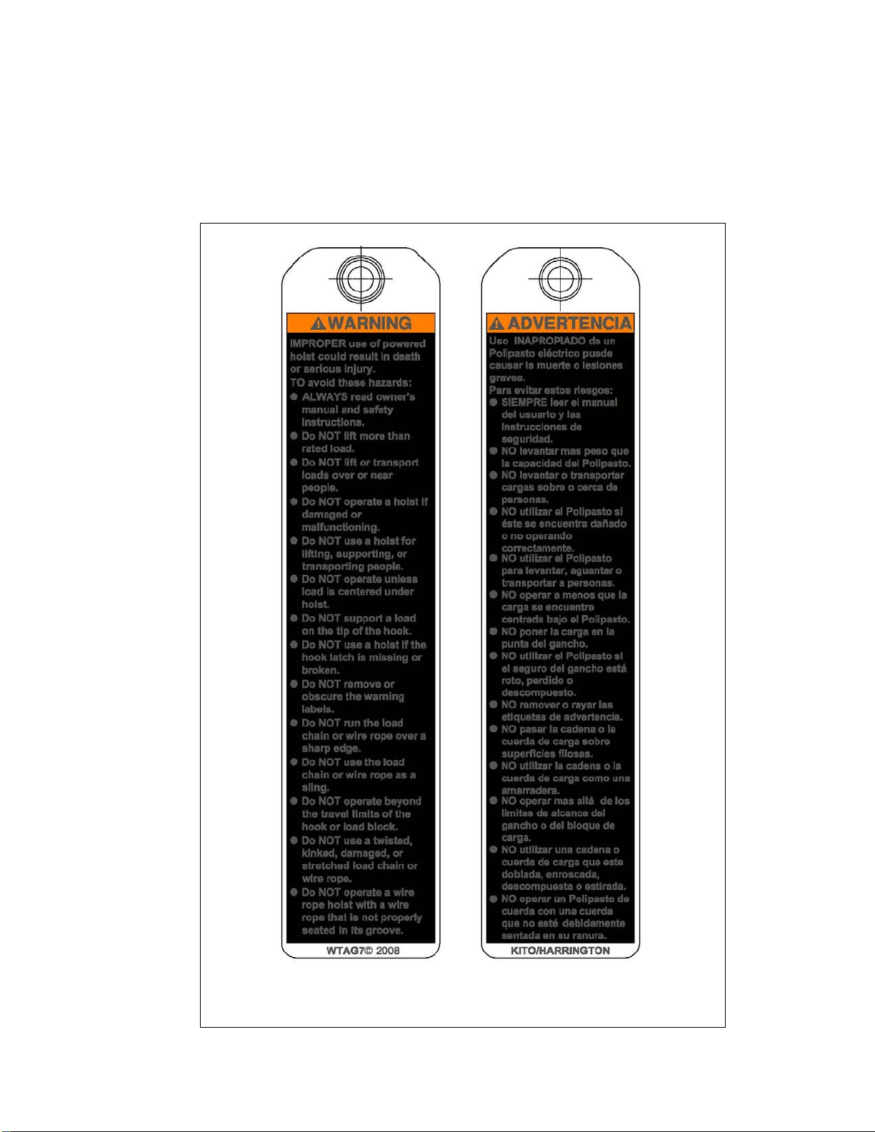
1.2 Warning Tags and Labels
The warning tag illustrated below in Figure 1-1 is supplied with each hoist shipped from the factory. If the tag is
not attached to your hoist’s pendant cord or cylinder control, order a tag from your dealer and install it. Read
and obey all warnings attached to this hoist. Tag is not shown actual size.
front back
Figure 1-1 Warning Tag Attached to Hoist
7
Page 8
2.0 T ec hnical Inf ormation
2.1 Specifications
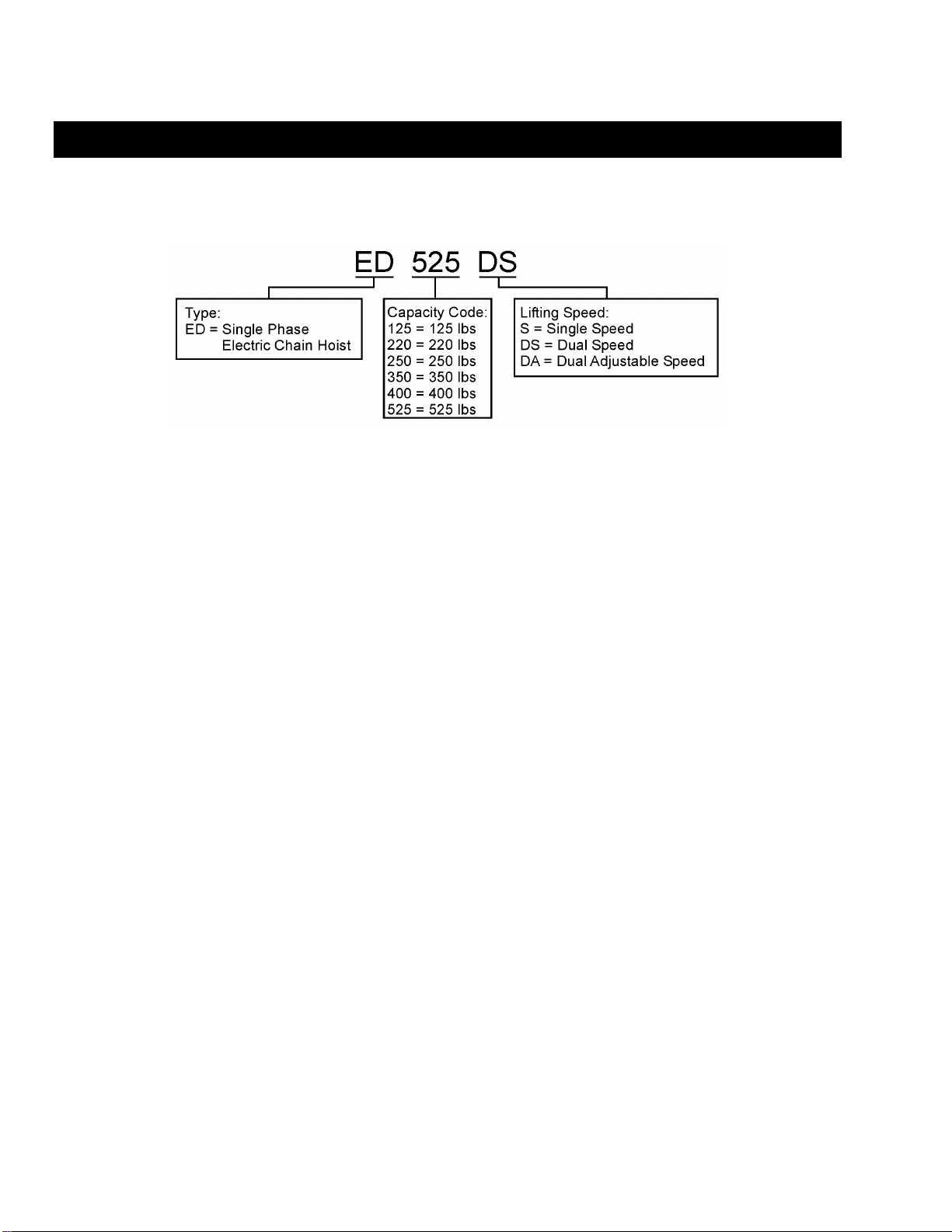
2.1.1 Product Code
2.1.2 Features and General Specifications
Push Button Pendant Control – On S & DS Models
One-Hand Cylinder Control – On DA Model
Double Braking System – A Weston style load brake and a regenerative brake
Upper Limit Switch –
Over-Travel Protection – Friction clutch integrated with load brake and engineered to
Ergonomic Design – (DA Models) Designed for one-hand control and precision
Smooth Operation – Gears are immersed in an oil bath and have deep groove ball
Quick Disconnect Hook – (DA Models) Convenient for other below the hook devices
Corrosion Resistant Load Chain – Nickel-plated, heat treated alloy chain for long life
Weight/Size – Light weight and compact size, easy to install, move, or store
Low Headroom –
Chain Container – Standard
Die cast aluminum body provides low headroom, perfect for
tight quarters
ED III Model Only
protect the hoist from overwinding
loading
and needle bearings to support rotating components
2.1.3 Operating Conditions and Environment
Temperature range: -4° to +104°F (-20° to +40°C)
Humidity:
Noise Level:
Enclosure Rating: Hoist B ody IP54
Supply Voltage: Standard 120V-1-60
ASME Duty Classification: H2
85% or less
83 dB or less (A scale: measured 1meter away from electric
chain hoist)
Push Button Pendant IP65
Cylinder with bellow IP44
Cylinder without bellow IP22
8
Page 9
Net Weight
Speed
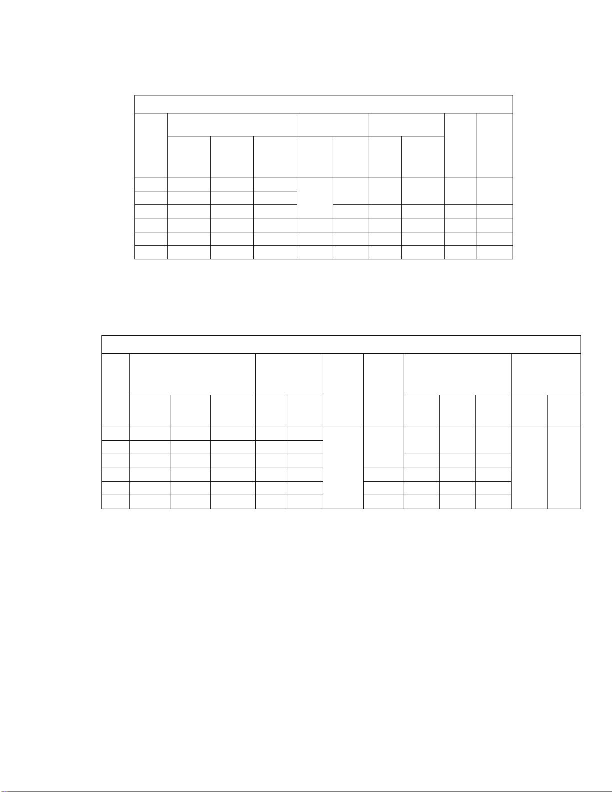
Table 2-1 Hoist Motor Rati ng
Output
(Hp)
0.4
Motor
Rated
Current
at 115V
(Amps)
5 30 180 15 5
Product Code
Cap.
(lbs.)
125 ED125S ED125DS ED125DA
220 ED220S ED220DS ED220DA
250 ED250S ED250DS ED250DA 6 20 120 10 6
350 ED350S ED350DS ED350DA 0.8 10 30 180 20 10
400 ED400S ED400DS ED400DA 0.4 6 20 120 10 6
525 ED525S ED525DS ED525DA 0.8 10 30 180 20 10
Single
Speed
S Model
Dual
Speed
DS Model
Dual
Adjustable
DA Model
Intermittent Duty
Rating
Duty
Rating
% ED
Max. Start
(Times/Hr)
Freq.
Short
Time
Duty
Rating
(min)
Rated
Current
at 120V
(amps)
Table 2-2 Hoist S pecifi cations
Cap.
(lbs.)
Single
S Model
125 ED125S ED125DS ED125DA 69 69/13
220 ED220S ED220DS ED220DA 43 43/10
250 ED250S ED250DS ED250DA 26 26/10 24 25 32
350 ED350S ED350DS ED350DA 66 66/13 5 33 34 40
400 ED400S ED400DS ED400DA 26 26/10 4 24 25 32
525 ED525S ED525DS ED525DA 44 44/10 5 33 34 40
Product Code
Dual
Speed
DS Model
Dual
Adjustable
DA Model
Lifting Speed
(ft/min)
S
Model
DS &
DA
Model
Load
Chain
Wire
Diameter
(mm) x
Chain Fall
Lines
4.0 x 1
Load
Sheave
Pockets
Weight for
Additional One
(lbs.)
S
Model
4
23 24 31
DS
Model
DA
Model
Foot of Lift
(lbs.)
S
Model
0.26 0.29
Model
DS
9
Page 10
Standard Lift
L
ton Cord
L
j
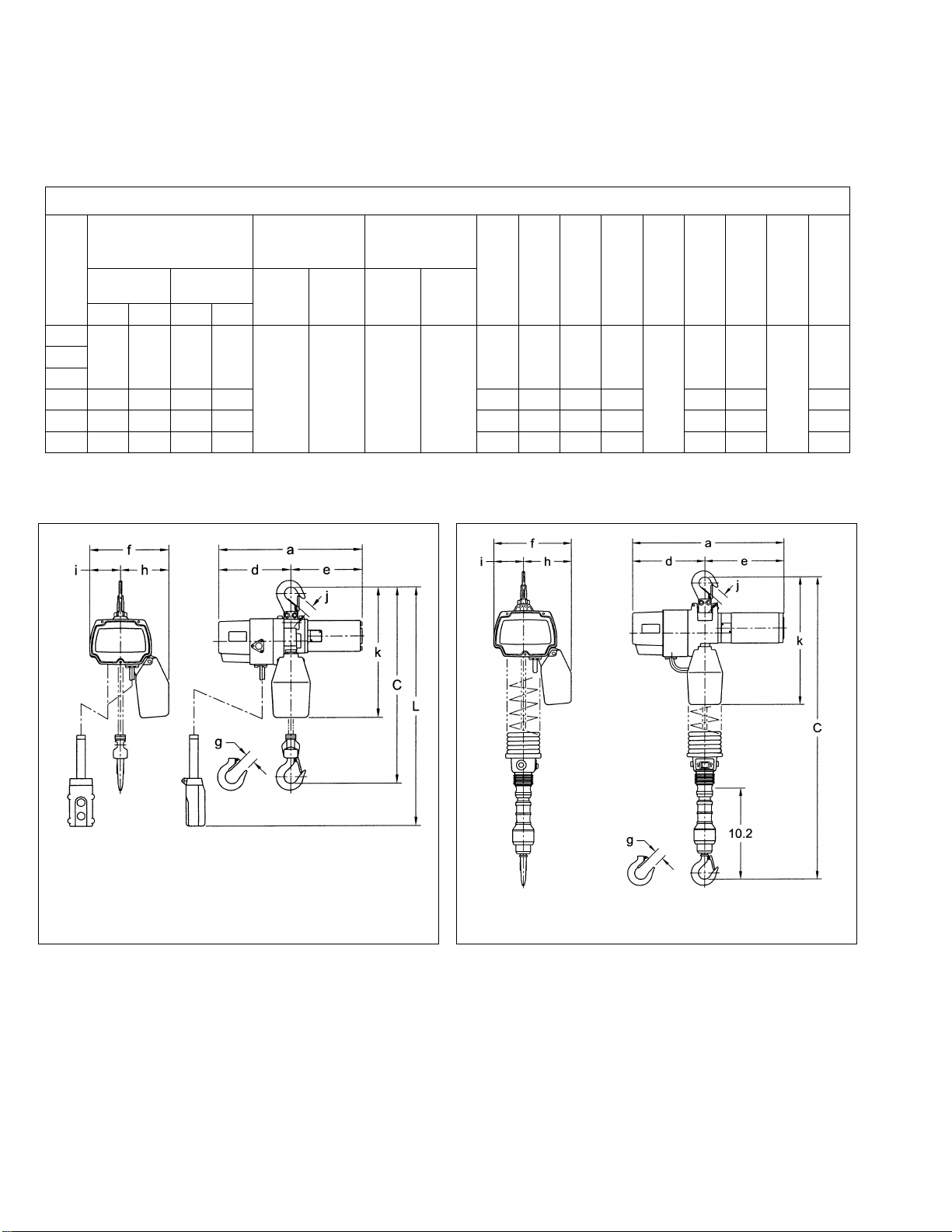
Hoist Dimension DA Models
2.2 Dimensions
Table 2-3 Hoist Dimensions
Headroom
C
Cap.
(lbs)
125
220
250
350 12.8 13.0 37.6 37.8 16.9 8.1 8.8 8.6 5.3 3.3 14.3
400 11.8 12.4 36.6 37.2 14.6 7.4 7.2 8.1 4.9 3.1 13.4
525 12.8 13.0 37.6 37.8 16.9 8.1 8.8 8.6 5.3 3.3 14.3
S & DS
Model
EDII EDIII EDII EDIII
11.8 12.4 36.6 37.2
(in)
DA
Model
(ft)
S & DS
Model
10 6 8 Coiled
DA
Model
Push But
S & DS
Model
(ft)
S & DS
Model
a
d
e
(in)
(in)
(in)
14.6 7.4 7.2 8.1
f
(in)
g
(in)
1.0
h
(in)
4.9 3.1
i
(in)
(in)
1.0
k
(in)
13.4
Figure 2-1 Hoist Dimension for S and DS Models
(See Table 2-3)
Figure 2-2
(See Table 2-3)
10
Page 11
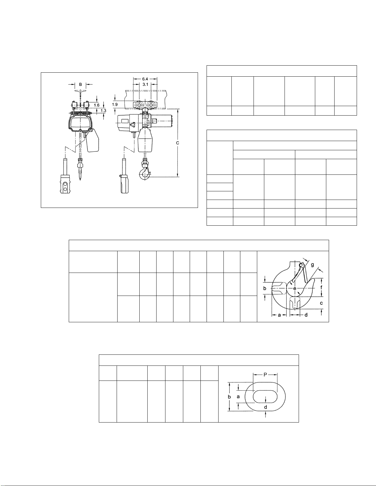
Figure 2-3 ET525 Mini Trolley (See Tables 2-4 and 2-5)
Beam Width
B
Min. Ra diu s
Capacity
a
b
c
d
e
f
g
Cap.
Product
d
b
P
Table 2-4 Mini Trolley Dimensions
Maximum
Capacity
(lbs.)
525 ET525 1.97 – 3.94 23.6 4.0 5.0
Product
Code
Table 2-5 Mini Trolley Headroom
Cap.
(lbs.)
125
220
250
350
400
525
Table 2-6 ED Hook Dimensions*
Adjustable
(in)
for Curve
(in)
Net
Weight
(lbs.)
Headroom C (i n.)
ED II ED III
S & DS
Model
9.9
10.9 35.7 11.1 35.9
9.9 34.5 10.5 35.3
10.9 35.7 11.1 35.9
DA Model
34.5
S & DS
Model
10.5
DA Model
Approx.
Shpg.
Weight
(lbs.)
35.3
(lbs.)
125 to 525
Hook
Top 0.8 0.3 0.7 0.3 1.3 1.2 1.0
Bottom 0.8 0.5 0.7 0.5 1.4 1.4 1.0
(in)
(in)
(in)
(in)
*See Table 5-5 for discard dimensions.
(in)
(in)
(in)
Table 2-7 ED Chain Dimension s
a
(lbs)
125
to
525
Code
(All Models) 0.16 0.20 0.53 0.48
(in)
(in)
(in)
(in)
11
Page 12
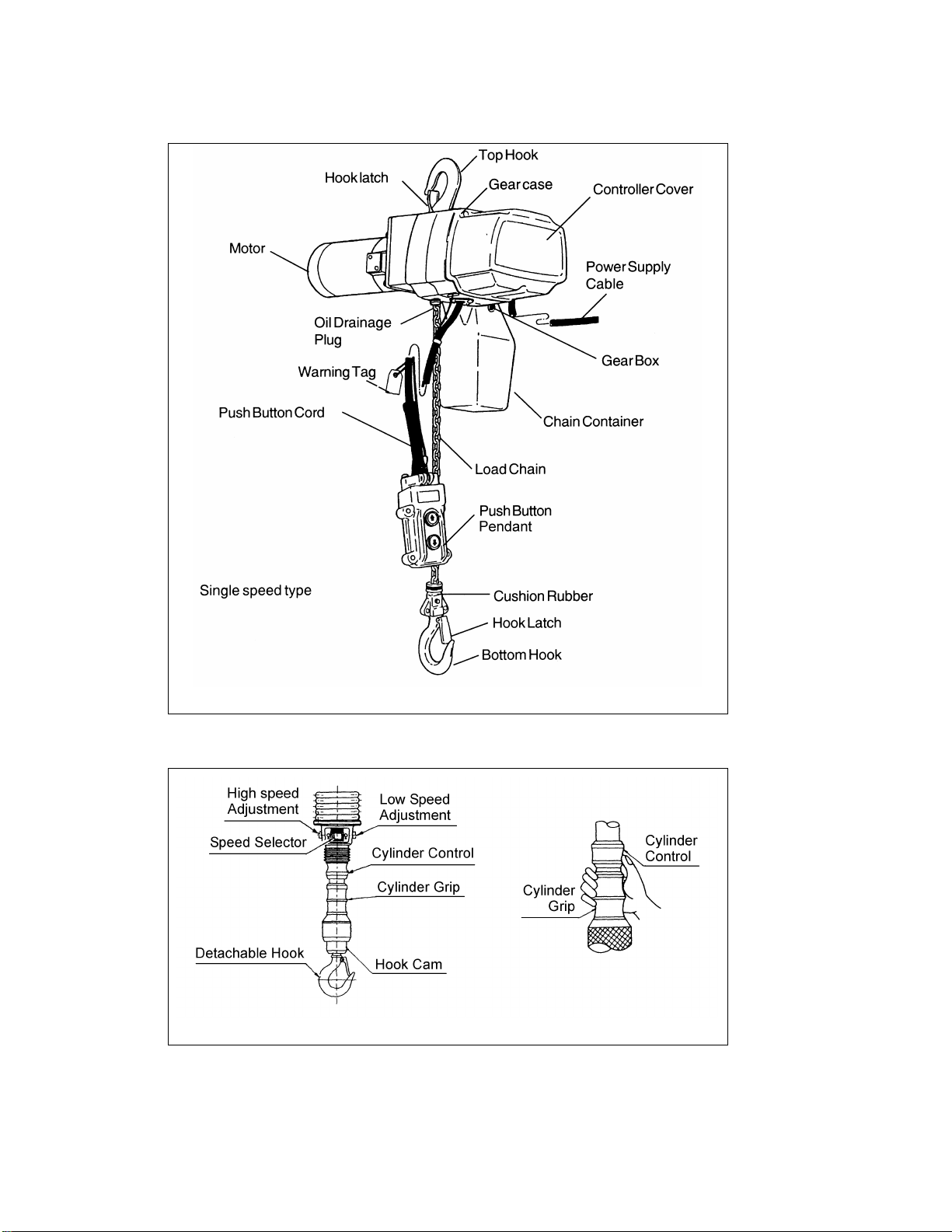
2.3 Part Names
Figure 2-4 ED Single and Dual Speed Part Names
Figure 2-5 ED Dual Adjustable (DA) Speed Cylinder Control Part Names
12
Page 13
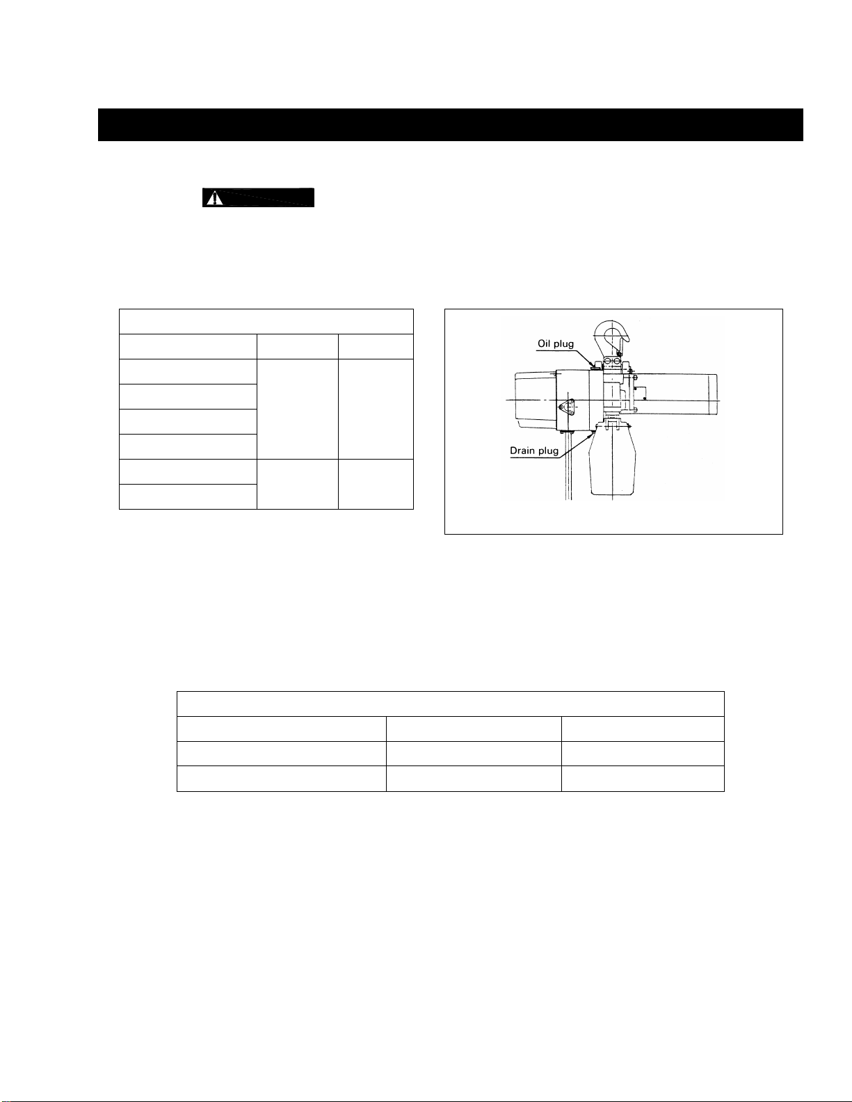
Figure 3-1 Oil Plug Locations
3.0 Pre-operational Procedures
3.1 Fill Gear Box with Oil
3.1.1
purchased from Harrington. Refer to parts list for part number.
3.1.2 For a new hoist the correct quantity and type of oil is pre-supplied in the gearbox.
3.1.3 Refer to Section 6.1 when replacing the gear oil or checking the gear oil level.
Table 3-1 Amount of Gear Oil
Capacity Code quarts liters
125
220
250
400
350
525
Use only Harrington ED brand oil. The oil is specially blended and should be
0.28 0.27
0.37 0.35
3.2 Chain
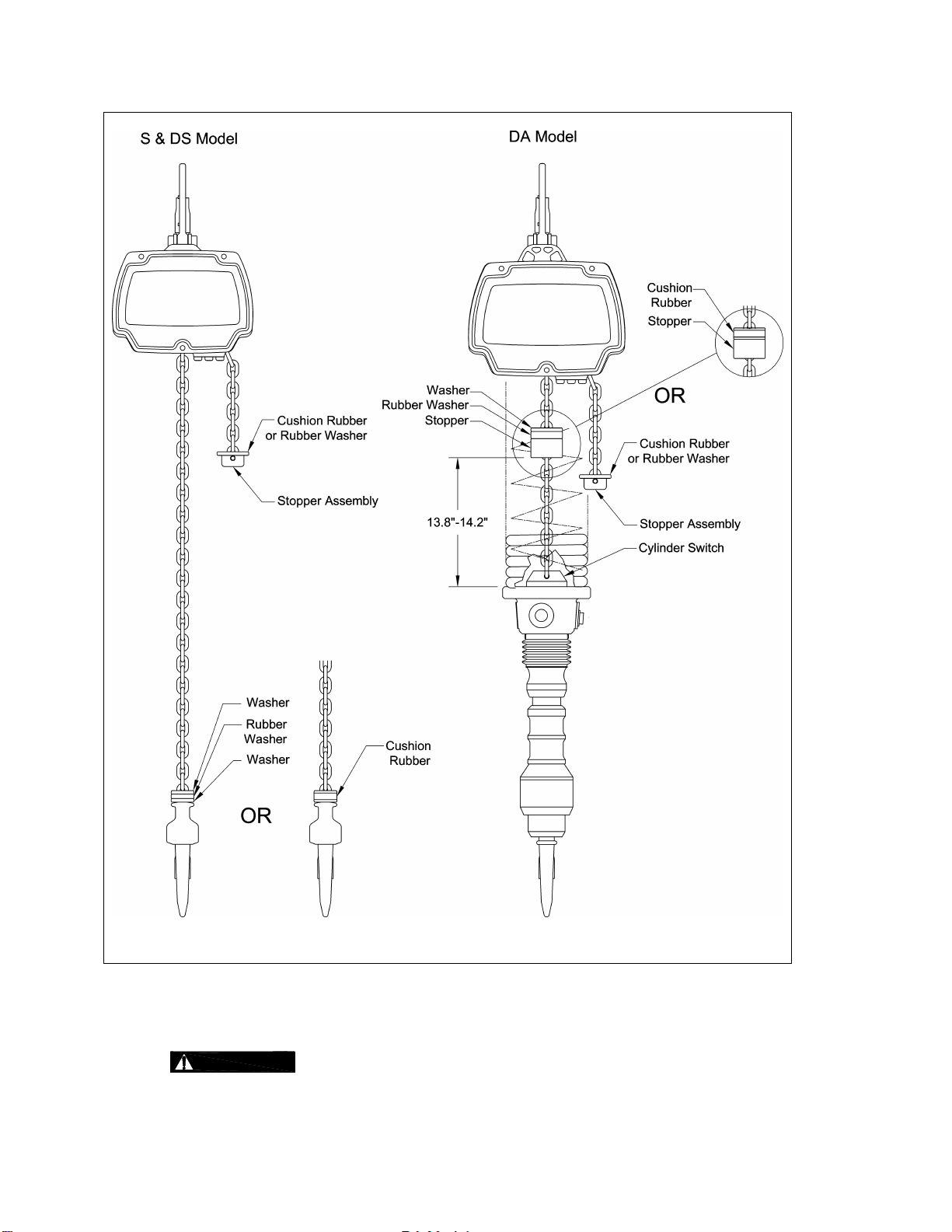
3.2.1 The quantity and location of the chain components including Cushion Rubbers, Washers and Stopper
Assemblies depend on the hoist model, capacity. Never operate the hoist with incorrect, missing or
damaged chain components. Refer to the hoist's nameplate, Table 3-2, and Figure 3-2 and ensure
that all chain components are in the correct location and properly installed.
Table 3-2 Chain Stopper Placement
Capacity Code Load Side No Load Side
S & DS Adjacent to bottom yoke Last link
DA 13.8”-14.2” Last link
13
Page 14
3.3 Load Chain Lubrication
Figure 3-2 Chain Component Arrangement for Hoists with Upper Limit Switch Only
3.3.1 Always lubricate load chain weekly, or more frequently, depending on severity of service.
3.3.2
oil lubrication will accelerate Load Chain wear.
Always make sure to apply ISO VG 46 or 48 or equivalent machine oil. Insufficient
14
Page 15
3.4 Chain Container
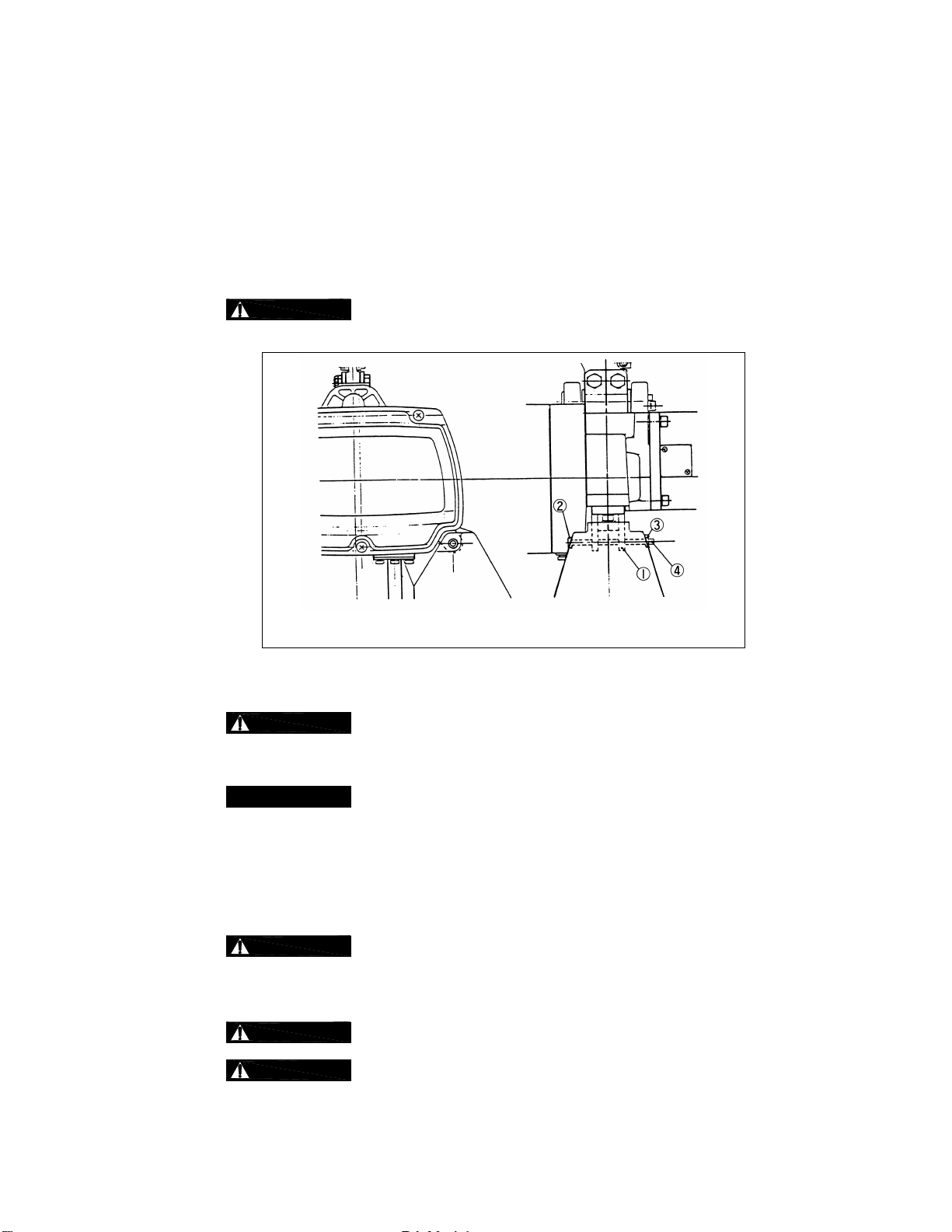
3.4.1 Follow the instructions below to install the Chain Container. Refer to Figure 3-3.
1) Feed the Load Chain into the Chain Container beginning with the no-load end. Take care to avoid
twisting or tangling the Load Chain.
2) Attach the Chain Container to the Chain Guide (1) with the Socket Bolt (2) and the U-Nut (3).
3) Attach the Split Pin (4) to prevent the U-Nut (3) from backing off.
4) Bend the Split Pin ends 90
o
or more.
5)
fasteners/hardware are missing.
3.5 Mounting Location
3.5.1
structure are adequate to support the hoist and its loads. If necessary consult a professional that is
qualified to evaluate the adequacy of the suspension location and its supporting structure.
Do not use the Chain Container if any parts are damaged or if any
Figure 3-3 Chain Container Installation
Prior to mounting the hoist ensure that the suspension and the supporting
3.5.2
3.6 Mounting the Hoist
3.6.1 ET525 Mini Trolley – Refer to Section 3.8 for installation instructions
3.6.2 Manual Trolley - Follow instructions in Owner's Manual provided with the trolley.
3.6.3 Hook Mounted to a Fixed Location - Attach the hoist’s top hook to the fixed suspension point.
3.6.4
the hook’s latch is engaged.
3.7 Electrical Connection s
3.7.1
3.7.2
been de-energized (disconnected). Lock out and tag out in accordance with ANSI Z244.1 “Personnel
Protection -Lockout/Tagout of Energy Sources”.
See Section 6.6 for outdoor installation considerations
Ensure that the fixed suspension point rests on the center of the hook’s saddle and
Ensure that the voltage of the electric power supply is proper for the hoist or trolley.
Before proceeding, ensure that the electrical supply for the hoist or trolley has
15
Page 16
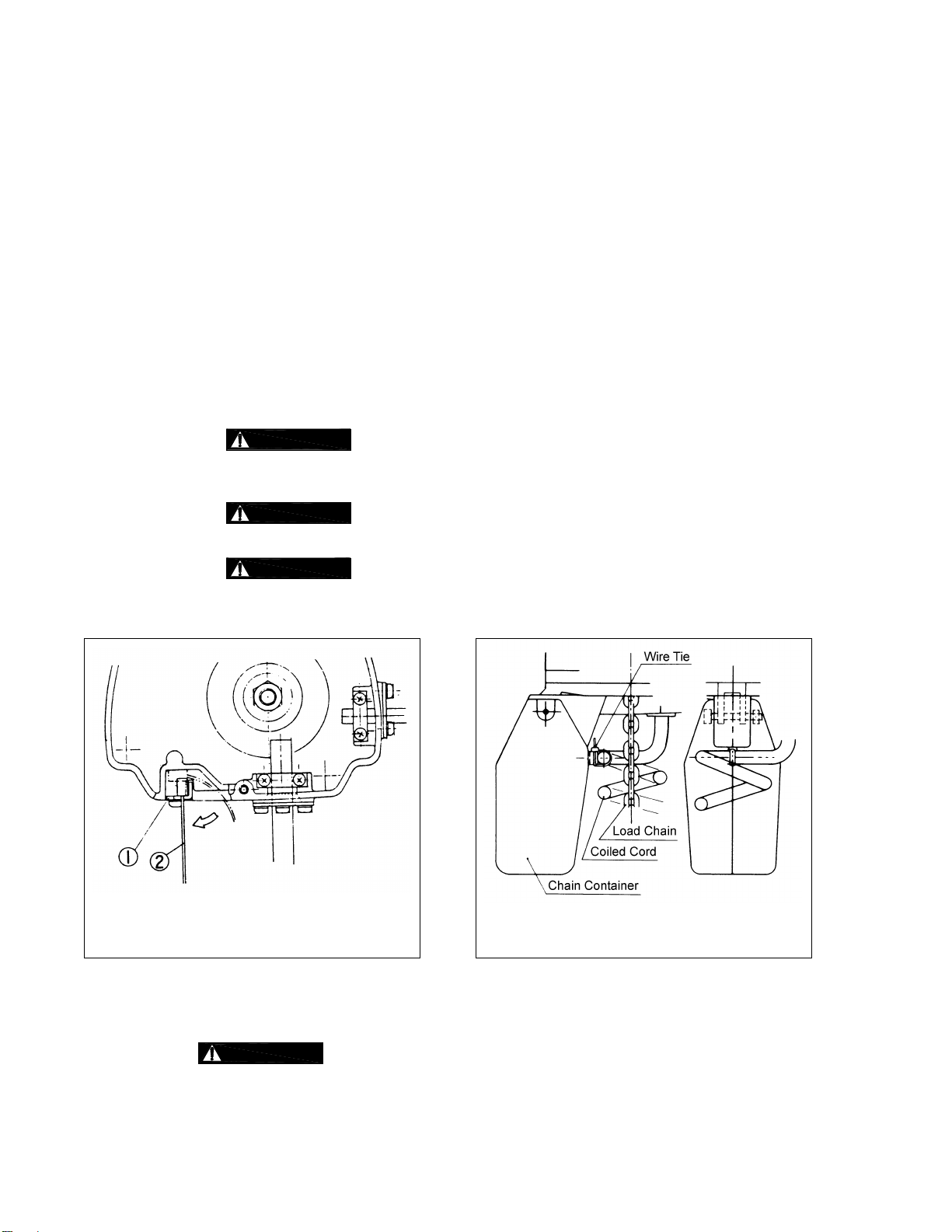
Figure 3-4 Diagram for Pendant Type
Figure 3-5 Diagram for Cylinder Type
3.7.3 This instruction applies to installations where the hoist is installed hook mounted to a fixed suspension
point or installed on a manual trolley. In this case the hoist is controlled by a pendant with two push
buttons – one for raising and one for lowering.
Pendant Cord
The Pendant Cord is hard wired to the hoist. Make this connection as follows:
1.) Single and Dual Speed Models (S & DS)
Refer to Figure 3-4.
The Push Button Cord is factory installed onto the hoist body.
Attach the Strain Relief Wire (2) to Cable Support L (1).
2.) Dual Speed Cylinder Model (DA)
Refer to Figure 3-5.
The Coiled Push Button Cord is factory installed onto the hoist body.
Attach the Coiled Push Button Cord to the Chain Container with the Wire Tie provided, so
that the Load Chain hangs in the center of the Coiled Cord and the clamp part of the Wire
Tie faces up and away from the Load Chain.
3.)
pulled when the Strain Relief Wire is not connected to the hoist body. ALWAYS make sure
that the Strain Relief Wire is properly attached to the hoist body.
4.)
Load Chain before fitting the Coiled Cord to the Chain Container.
5.)
the Wire Tie faces up and away from the Load Chain
Short circuit and electric shock may result if the Push Button Cord is
To avoid wear between the Load Chain and the Chain Guide, straighten
To avoid damaging the Coiled Cord, attach the Chain Container so that
Push Button Cord Installation
Power Supply Cable – Hoist Connection
A 14-gauge Power Supply Cable is supplied with hoist.
use 3-conduction cable with an adequate gauge size.
Push Button Cord Installation
When the power source is far away and an extension supply cable is required,
16
Page 17

Power Supply Cabl e - Installation
If the hoist is hook mounted to a fixed support ensure that the Power Supply Cable is properly
installed and supported between the hoist and the electrical power supply.
If the host is installed on a manual trolley, then the Power Supply Cable must be installed along the
beam that the trolley runs on. For curved beams a special cable suspension system will be
needed, and this instruction does not apply. For straight beams install the Power Supply Cable as
follows:
Install a Guide Wire System parallel to the beam.
For a manual trolley the Guide Wire should be positioned slightly outside the hoist's Cable
Support.
3.7.4 Connection to Electrical Power Source - The white and black wires of the Power Supply Cable should
be connected to an Electric Power Disconnect Switch or Circuit Breaker.
3.7.5 Fuse/Breaker Capacity - The hoist's power supply should be equipped with overcurrent protection such
as fuses, which should be selected for 110% to 120% of total listed full load amperage, and should be
dual element time-delay fuses. Refer to the motor nameplate for the full load amperage draw.
3.7.6
Grounding - An improper or insufficient ground connection creates an electrical
shock hazard when touching any part of the hoist or trolley. In the Power Supply Cable the ground wire
will be either Green with Yellow stripe or solid Green. It should always be connected to a suitable
ground connection. Do not paint the trolley wheel running surfaces of the beam as this can affect
grounding.
3.8 Mini Trolley Installat ion
3.8.1 Mini Trolley - Follow instructions below to install the trolley. Refer to Figure 3-6.
1) Remove the Top Hook Assembly from the hoist.
2) Refer to Table 3-3 for placement of Adjusting Spacers for the flange width “B” of the traversing beam.
The position of Adjusting Spacers differs with flange width. If the beam flange width is not listed in
Table 3-3, use the next size smaller and make adjustments in accordance with step 3. Use all 32
Adjusting Spacers provided.
Table 3.3 Quantity and Position of Trolley Spacers
Flange
Width
(in)
2 8 6 4 6 8
2 5/16 6 7 4 8 7
2 1/2 6 8 4 8 6
2 11/16 5 8 4 9 6
2 13/16 5 9 4 9 5
3 4 10 4 10 4
3 1/4 3 11 4 11 3
3 5/16 3 11 4 11 3
3 9/16 2 12 4 12 2
3 11/16 1 12 4 13 2
3 7/8 0 13 4 14 1
3 15/16 0 14 4 14 0
Outside
Left Frame
Inside Left
Frame
Number of spacers
Inside
Yoke
Inside
Right
Frame
Outside
Right
Frame
17
Page 18

3) Refer to Figure 3-6 and assemble the Trolley Frames, Adjusting Spacers and Socket Bolts onto the
Top Yoke. Install and hand tighten the Hex Nuts on the Socket Bolts. Verify that dimension “A” is
approximately 0.12 - 0.16 in (3-4mm) greater than “B” (flange width). If "A" does not fall within the
specified range, move Adjusting Spacers from the inside of the Trolley Frame to the outside or from the
outside to the inside as necessary to obtain the proper "A" dimension, irrespective of the numbers in
Table 3-3.
4) Install the trolley and hoist onto traversing beam using one of the following 2 methods:
Preferred Method – Sliding adjusted the trolley connected with hoist onto the traversing beam
from the beam end is the most convenient and recommended method. If the trolley can be
mounted from the end of the beam then: Remove the trolley end-stop from the beam and set
the trolley on the beam from the end. Securely re-install the trolley end stop on the beam.
Optional Method – If the trolley cannot be mounted from the end of the beam, loosen the Hex
Nuts and spread the trolley Frames. Lift the trolley and hoist onto the beam from below. Push
the trolley frames together, adjust the spacing as in accordance with Step 3 and hand tighten
the hex Nuts.
5) Check for contact between all four Trolley Wheels and the rail surface. Shift the Trolley Frame until all
Trolley Wheels rest on the rail surface. Tighten the Hex Nuts and install the two (2) U-Nuts onto the
Socket Bolts tighten against the Hex Nuts. Install the Split Pins onto the Socket Bolts and bend
securely.
6)
Incorrect number of Adjusting Spacers may cause the trolley to not move or to
drop. To avoid these hazards, always make sure to use all 32 spacers and confirm that A - B = 0.12 -
0.16 in (3-4mm).
7)
To prevent the trolley from dropping, firmly fasten the Socket Bolt, Nut and U-Nut.
Insert Split Pin and bend the ends 90 degrees or more.
Figure 3-6 Mini Trolley Installation
3.8.2
For all trolley suspended elect ric chain hosts, rail stops m ust be installed at each
end of the rail. Failure to install rail stops will allo w th e ho ist and tr olle y to fall of f the end of the r ail and
thus cause and accident that could resutt in injury and/ or property damage. The stops must be
positioned so as to not exert impact force on the electric chain hoist frame or trolley wheels. They must
contact the ends of the trolley side frames.
18
Page 19

3.9 Pre-operational Checks and Trial Operation
3.9.1
Confirm the adequacy of the rated capacity for all slings, chains, wire ropes and all
other lifting attachments before use. Inspect all load suspension members for damage prior to use and
replace or repair all damaged parts.
3.9.2
Verify and correct all chain irregularities prior to operating the hoist. For reference
see Section 3.2.
3.9.3 Measure and record the “k” dimension of all hooks on hoist. See Table 5-5 under Section 5,
“Inspection”.
3.9.4 Record the hoist's Code, Lot and Serial Number (from the name plate on the hoist; see Section 9) in
the space provided on the cover of this manual.
3.9.5 Ensure that the hoist is properly installed to either a fixed point, or trolley, whichever applies
3.9.6 If hoist is installed on a trolley, ensure that
trolley is properly installed on the beam, and
stops for the trolley are correctly positioned and securely installed on the beam.
3.9.7 Ensure that all nuts, bolts and split pins (cotter pins) are sufficiently fastened.
3.9.8 For S and DS Models - Pull down on the Pendant and ensure that the Cord Strain Relief Cable takes
the force, not the Pendant Cord.
3.9.9
Check supply voltage before everyday use. If the voltage varies more than 10% of
the rated value, electrical devices may not function normally.
3.9.10 Confirm proper operation.
Before operating read and become familiar with Section 4 - Operation.
Before operating ensure that the hoist (and trolley) meets the Inspection, Testing and Maintenance
requirements of ANSI/ASME B30.16.
Before operating ensure that nothing will interfere with the full range of the hoist’s (and trolley’s)
operation.
19
Page 20

R LIFTING SYSTEM WHEN UNDER THE
• Read ANSI/ASME B30.16 and ANSI/ASME B30.10.
4.0 Operation
4.1 Introduction
DO NOT WALK UNDER A SUSPENDED LOAD
HOIST OPERAT ORS SHALL BE REQUIRED TO READ THE OPER ATION SECTION O F THIS MANUAL, THE
WARNINGS CONTAINED IN THIS MANUAL, INSTRUCTION AND WARNING LABELS ON THE HOIST OR
LIFTING SYSTEM , AND THE OPERATION SEC TIONS OF ANSI/ASM E B30.16 and ANSI/ASM E B30.10. THE
OPERATOR SHALL ALSO BE REQUIRED TO BE FAMILIAR WITH THE HOIST AND HOIST CONTROLS
BEFORE BEING AUTHORIZED TO OPERATE THE HOIST OR LIFTING SYSTEM.
HOIST OPERATORS SHOULD BE TRAINED IN PROPER RIGGING PROC EDURES FOR THE ATTACHMENT
OF LOADS TO THE HOIST HOOK .
HOIST OPERATORS SHOULD BE TRAINED TO BE AWARE OF POTENTIAL MALFUNCTIONS OF THE
EQUIPMENT THAT REQUIRE ADJUSTMENT OR REPAIR, AND TO BE INSTRUCTED TO STOP OPERATION
IF SUCH MALFUNCTIONS OCCUR, AND TO IMMEDIATELY ADVISE THEIR SUPERVISOR SO CORRECTIVE
ACTION CAN BE TAKEN.
HOIST OPERAT ORS SHOULD HAVE NORMAL DEPTH PER CEPTION, FIELD OF VISION, REACTIO N TIME,
MANUAL DEXTERITY, AND COORDINATION.
HOIST OPERATORS SHOULD NOT HAVE A HISTORY OF OR BE PRONE TO SEIZURES, LOSS OF
PHYSICAL CONTROL, PHYSICAL DEFECTS, OR EMOTIONAL INSTABILITY THAT COULD RESULT IN
ACTIONS OF THE OPERATOR BEING A HAZARD TO THE OPERATOR OR TO OTHERS.
HOIST OPERATORS SHOULD NOT OPERATE A HOIST O
INFLUENCE OF ALCOHOL, DRUGS, OR MEDICATION.
OVERHEAD HOISTS ARE INTENDED ONLY FOR VERTICAL LIFTING SERVICE OF FREELY SUSPENDED
UNGUIDED LOADS. DO NOT
ARE NOT FREELY SUSPENDED, OR LOADS THAT ARE GUIDED.
USE HOI ST FOR LOADS T HAT ARE NOT LI FTED VERTIC ALLY, LOADS T HAT
• Read the hoist manufacturer’s Operating and Maintenance Instructions.
• Read all labels attached to equipment.
The operation of an overhead hoist involves more than activating the hoist’s controls. Per the ANSI/ASME B30
standards, the use of an overhead hoist is subject to c ertain hazards that cannot be m itigated by engine ered features,
but only by the exercise of intelligenc e, care, common sense, and experi ence in anticipating the effec ts and results of
activating the hoist’s controls. Use this guidance in conjunction with other warnings, cautions, and notices in this manual
to govern the operation and use of your overhead hoist.
20
Page 21

4.2 Shall’s and Shall Not’s for Operation
Improper operation of a hoist can create a poten tially haz ardous
situation which, if not avoided, could result in death
and substantial property damage. To avoi d such a poten tially
hazardous situation THE OPERATOR SHALL:
or serious i njury,
• NOT lift more than rated load for the hoist.
• NOT operate unless load is centered under hoist.
• NOT use damaged hoist or hoist that is not working
properly.
• NOT use hoist with twisted, kinked, damaged, or
worn chain.
• NOT use the hoist to lift, support, or transport
people.
• NOT lift loads over people.
• NOT apply load unless load chain is properly
seated in the load sheave (and idle sheave for hoist
with two chain falls).
• NOT use the hoist in such a way that could result in
shock or impact loads being applied to the hoist.
• NOT attempt to lengthen the load chain or repair
damaged load chain.
• NOT operate hoist when it is restricted from forming
a straight line from hook to hook in the direc tion of
loading.
• NOT us e load chain as a sling or wrap load chain
around load.
• NOT apply the load to the ti p of the hook or to the
hook latch.
• NOT apply load if binding prevents equal loading
on all load-supporting chains.
• NOT operate beyond the limits of the load chain
travel.
• NOT operate hoist with m issing/damaged cushion
rubbers, stoppers or washers.
• NOT leave load support ed by the h oist unatte nded
unless specific precautions have been taken.
• NOT allow the chain, or hook to be used as an
electrical or welding ground.
• NOT allow the chain, or hook to be touched b y a
live welding electrode.
• NOT remove or obscure the warnings on the hoist.
• NOT operate a hoist on which the safety placards
or decals are missing or illegible.
• Be familiar with operating controls, procedures, and
warnings.
• Make sure the unit is securely attached to a
suitable support before applying load.
• Make sure load slings or other approved single
attachments are properl y sized, rigged, and seate d
in the hook saddle.
• Take up slack carefully - make sure load is
balanced and load-holding action is secure bef ore
continuing.
• Mak e sure all persons stay clear of the supp orted
load.
• Protect the hoist’s load chain from weld splatter or
other damaging contaminants.
• Report Malfunctions or unusual performances
(including unusual noises) of the hois t and remove
the hoist from service until the malfunction or
unusual performance is resolved.
• Make sure hoist limit switches function properly.
• Warn personnel before lifting or moving a load.
• Warn personnel of an approaching load.
21
Page 22

Improper operation of a hoist can create a poten tially haz ardous
situation which, if not avoided, could result in minor
injury
, or property damage. To avoid such a potentiall y haz ardous
situation THE OPERATOR SHALL:
or moderate
• Maintain a firm footing or be otherwise secured
when operating the hoist.
• Check brake function by tensioning the hoist prior
to each lift operation.
• Use hook latches. Latches are to retain slings,
chains, etc. under slack conditions only.
• Make sure the hook latches are closed and not
supporting any parts of the load.
• Make sure the load is free to move and will clear all
obstructions.
• Avoid swinging the load or hook.
• Make sure hook travel is in the sam e direction as
shown on controls.
• Inspect the hoist regularly, replace damaged or
worn parts, and keep appropriate records of
maintenance.
4.3 Hoist Controls
4.3.1 Single Speed Pendant Control – When using the pendant control depress the up button to raise the
hoist or the down button to lower the hoist as shown in Figure 4-1 below. To stop motion release the
buttons.
• Use the hoist manufacturer’s recommended parts
when repairing the unit.
• Lubricate load chain per hoist manufacturer’s
recommendations.
• NOT use the hoist load limiting or warning device to
measure load.
• NOT use lim it switches as routine o perating stops.
They are emergency devices only.
• NOT allow your attention to be diverted from
operating the hoist.
• NOT allow the hoist to be subjected to sharp
contact with other hoists, structures, or objects
through misuse.
• NOT adjust or repair the hoist unless qualified to
perform such adjustments or repairs.
4.3.2 Dual Speed Pendant Control – Pendant controls supplied with dual speed hoists have two step control
buttons. For low speed depress the button to the first step and for high speed depress the button fully
to the second step. Use the up button to raise the hoist or the down button to lower the hoist as shown
in Figure 4-1 below. To stop motion release the buttons.
4.3.3
Make sure the motor completely stops before reversing direction.
Figure 4-1 Push Button Pendant Control
22
Page 23

4.3.4 Dual Speed Pendant Model (DS) Low Speed Adjustment – The Pendant has a low speed adjustment
which allow the low speed to be adjusted to suit the application or compensate for low or high supply
voltage. Adjust the low speed as follows:
1)
Before proceeding, ensure that the electrical supply for the hoist or trolley
has been de-energized (disconnected). Lock out and tag out in accordance with ANSI Z244.1
“Personnel Protection -Lockout/Tagout of Energy Sources”.
2) Open the back cover of the Pendant (as depicted in Figure 4-2).
3) Turn the Speed Adjustment Screw clockwise to increase the low speed or counterclockwise
to decrease it.
4) Close the back of the push button switch.
Figure 4-2 Speed Adjustment for Dual Speed Pendant
4.3.5 Dual Speed Cylinder Control (DA) –The in-line hand grip and switch assembly is directly attached to
the Bottom Hook. As illustrated in Figure 4-3, the switch is cylinder shaped.
Lifting And Lowering - The load is lifted when the Cyninder Control is pushed up and lowered when
pushed down.
Speed Selection – Press the Speed Selector Switch to select low or high speed. “H” on the left
side is high speed and “L” on the right is low speed. The red light on the left illuminates when high
speed is selected and the green light on the right illuminates when low speed is selected.
Figure 4-3 Dual speed Cylinder Control
23
Page 24

4.3.6 Dual Speed Cylinder Control (DA) Model (DS) Low and High Speed Adjustment – The controller has
speed adjustments which allow the lifting and lowering speeds to be adjusted to suit the application or
compensate for low or high supply voltage. Turn the Low Speed Adjustment Switch (right side of
operating box) or High Speed Adjustment Switch (left side of operating box, model ED3 only) with
screw driver or the knob provide to adjust the speed. To increase the speed, turn the speed
Adjustment Switch clockwise; to decrease, turn it counterclockwise. Refer to Figure 4-4 and Figure 4-5.
Figure 4-4 Low Speed Cylinder Adjustment
4.3.7 Dual Speed Cylinder Control (DA) Model Detachable Hook – The Bottom Hook on the cylinder control
DA model is removable. Remove and attach the Bottom Hook as follows:
1) Refer to Figure 4-3.
2) To detach the Bottom Hook rotate the Hook Cam to the left (counterclockwise).
3) To attach the Bottom Hook push the hook into the Hook Cam from the bottom until the hook
snaps in place. Make certain the Hook Cam is fully rotated into the closed position.
Always make sure the Hook Cam is completely locked and that the hook will
not detach.
4.4 Electric Chain Hoist with Trolley
4.4.1 To operate the electric chain hoist with trolley, move it horizontally by either pushing the lifted load or
the Load Chain.
4.4.2
pendant or the pendant cord may disconnect cord wires. Disconnectd wire(s) may cause a short circuit
in the hoist body or any surrounding conductor, giving the operator electric shock.
4.4.3
load.
Never pull the coiled cord, pendant or pendant cord. Pulling the coiled cord,
Always move the hoist horizontally by grasping the cylinder grip or pushing the
Figure 4-5 High Speed Cylinder Adjustment
24
Page 25

5.0 Inspection
5.1 General
5.1.1 The inspection procedure herein is based on ANSI/ASME B30.16. The following definitions are from
ANSI/ASME B30.16 and pertain to the inspection procedure below.
Designated Person – a person selected or assigned as being competent to perform the specific
Qualified Person – a person who, by possession of a recognized degree or certificate of
Normal Service – that distributed service which involves operation with randomly distributed loads
Heavy Service – that service which involves operation within the rated load limit which exceeds
Severe Service – that service which involves normal or heavy service with abnormal operating
duties to which he/she is assigned.
professional standing, or who, by extensive knowledge, training, and experience, has successfully
demonstrated the ability to solve or resolve problems relating to the subject matter and work.
within the rated load limit, or uniform loads less than 65% of rated load for not more than 25% of
the time.
normal service.
conditions.
5.2 Inspection Classification
5.2.1 Initial Inspection – prior to initial use, all new, altered, or modified hoists shall be inspected by a
designated person to ensure compliance with the applicable provisions of this manual.
5.2.2 Inspection Classification – the inspection procedure for hoists in regular service is divided into two
general classifications based upon the intervals at which inspection should be performed. The intervals
in turn are dependent upon the nature of the critical components of the hoist and the degree of their
exposure to wear, deterioration, or malfunction. The two general classifications are herein designated
as FREQUENT and PERIODIC, with respective intervals between inspections as defined below.
5.2.3 FREQUENT Inspection – visual examinations by the operator or other designated personnel with
intervals per the following criteria:
Normal service – monthly
Heavy service – weekly to monthly
Severe service – daily to weekly
Special or infrequent service – as recommended by a qualified person before and after each
occurrence.
5.2.4 PERIODIC Inspection – visual inspection by a designated person with intervals per the following
criteria:
Normal service – yearly
Heavy service – semiannually
Severe service – quarterly
Special or infrequent service – as recommended by a qualified person before the first such
occurrence and as directed by the qualified person for any subsequent occurrences.
25
Page 26

5.3 Frequent Inspection
5.3.1 Inspections should be made on a FREQUENT basis in accordance with Table 5-1, “Frequent
Inspection.” Included in these FREQUENT Inspections are observations made during operation for
any defects or damage that might appear between Periodic Inspections. Evaluation and resolution of
the results of FREQUENT Inspections shall be made by a designated person such that the hoist is
maintained in safe working condition.
All functional operating mechanisms for maladjustment and unusual sounds.
Operation of limit switch and associated components
Hoist braking system for proper operation
Hooks in accordance with ANSI/ASME B30.10
Hook latch operation
Load chain in accordance with Section 5.7
Load chain reeving for compliance with Section 3.2
Table 5-1 Freque nt Inspec tion
5.4 Periodic Inspect ion
5.4.1 Inspections should be made on a PERIODIC basis in accordance with Table 5-2, “Periodic Inspection.”
Evaluation and resolution of the results of PERIODIC Inspections shall be made by a designated
person such that the hoist is maintained in safe working condition.
5.4.2 For inspections where load suspension parts of the hoist are disassembled, a load test per ANSI/ASME
B30.16 must be performed on the hoist after it is re-assembled and prior to its return to service.
Requirements of frequent inspection.
Evidence of loose bolts, nuts, or rivets.
Evidence of worn, corroded, cracked, or distorted parts such as load blocks, suspension housing,
chain attachments, clevises, yokes, suspension bolts, shafts, gears, bearings, pins and rollers.
Evidence of damage to hook retaining nuts or collars and pins, and welds or rivets used to secure
the retaining members.
Evidence of damage or excessive wear of load and idler sheaves.
Evidence of excessive wear on motor or load brake.
Electrical apparatus for signs of pitting or any deterioration of visible controller contacts.
Evidence of damage of supporting structure or trolley, if used.
Function labels on pendant control stations for legibility.
Table 5-2 Periodic Inspection
Warning label properly attached to the hoist and legible (see Section 1.2).
End connections of load chain.
26
Page 27

5.5 Occasionally U sed Hoi sts
5.5.1 Hoists that are used infrequently shall be inspected as follows prior to placing in service:
Hoist Idle More Than 1 Month, Less Than 1 Year: Inspect per FREQUENT Inspection criteria in
Section 5.3.
Hoist Idle More Than 1 Year: Inspect per PERIODIC Inspection criteria in Section 5.4.
5.6 Inspection Records
5.6.1 Dated inspection reports and records should be maintained at time intervals corresponding to those
that apply for the hoist’s PERIODIC interval per Section 5.2.4. These records should be stored where
they are available to personnel involved with the inspection, maintenance, or operation of the hoist.
5.6.2 A long range chain inspection program should be established and should include records of
examination of chains removed from service so a relationship can be established between visual
observation and actual condition of the chain.
5.7 Inspection Methods and Criteria
5.7.1 This section covers the inspection of specific items. The list of items in this section is based on those
listed in ANSI/ASME B30.16 for the Frequent and Periodic Inspection. In accordance with ANSI/ASME
B30.16, these inspections are not intended to involve disassembly of the hoist. Rather, disassembly for
further inspection would be required if frequent or periodic inspection results so indicate. Such
disassembly and further inspection should only be performed by a qualified person trained in the
disassembly and re-assembly of the hoist.
Table 5-3 Hoist Inspection Methods and Criteria
Item Method Criteria Action
Functional operating
mechanisms.
Limit Switch
(model ED3)
Braking System
Operation
Hooks - Surface
Condition
Hooks - Fretting
wear
Visual, Auditory
Function
Function
Visual
Measure
Mechanisms should be properly adjusted and
should not produce unusual sounds when
operated.
Proper operation. Actuation of limit switch should
stop hoist.
Braking distance with rated capacity should not
exceed approximately five chain links.
Should be free of significant rust, weld splatter,
deep nicks, or gouges.
The "u" and "t" dimensions should not be less
than discard value listed in Table 5-5
Repair or replace
as required.
Repair or replace
as required.
Repair or replace
as required.
Replace.
Replace.
The "k" dimension should not exceed the
Hooks - Stretch Measure
measured value for discard from Table 5-5 (See
Replace.
Section 3.9).
Hooks - Bent Shank
or Neck
Visual
Shank and neck portions of hook should be free
of deformations.
Replace.
Should be free of significant rust, weld splatter,
Hooks - Yoke
Assembly
Visual
nicks, gouges. Holes should not be elongated,
fasteners should not be loose, and there should
Tighten or replace
as required.
be no gap between mating parts.
27
Page 28

Ball Guide
Table 5-3 Hoist Inspection Methods and Criteria
Item Method Criteria Action
Bearing parts and surfaces should not show
Hooks - Swivel
Bearing
Visual, Function
significant wear, and should be free of dirt, grime
and deformations. Hook should rotate freely with
Clean/lubricate, or
replace as required.
no roughness.
Latch should not be deformed. Attachment of
latch to hook should not be loose. Latch spring
Hooks - Hook
Latches
Visual, Function
should not be missing and should not be weak.
Latch movement should not be stiff - when
Replace.
depressed and released latch should snap
smartly to its closed position.
Cylinder Hook
Chuck -
(DA Model)
Load Chain Surface Condition
Load Chain - Pitch
and Wire Diameter
Load Chain Lubrication
Load Chain Reeving
Chain Container
(optional)
Visual, Function
Visual
Measure
Visual, Auditory
Visual
Visual
Ball Guide should not be worn or deformed. Ball
Guide should interact properly with the Spring
Collar to retain the hook shank.
Should be free of rust, nicks, gouges, dents and
weld splatter. Links should not be deformed, and
should not show signs of abrasion. Surfaces
where links bear on one another should be free of
significant wear.
The "P" dimension should not be greater than
maximum value listed in Table 5-6. The "d"
dimension should not be less than minimum value
listed in Table 5-6.
Entire surface of each chain link should be coated
with lubricant and should be free of dirt and grime.
Chain should not emit cracking noise when
hoisting a load.
Chain should be reeved properly through Load
Sheave - refer to Section 6.2. Chain, Cushion
Rubbers, Washers and Stoppers should be
installed properly
Container should not be damaged. Brackets
should not be deformed or missing.
Replace.
Replace.
Replace. Inspect
Load Sheave by
qualified person.
Clean/lubricate
(see Section 6.1).
Reeve/Install chain
properly.
Replace
Housing and
Mechanical
Components
Bolts, Nuts and
Rivets
Visual, Auditory,
Vibration,
Function
Visual, Check
with Proper Tool
Motor Brushes Measure, Visual
Contactor Contacts Visual
Hoist components including load blocks,
suspension housing, chain attachments, clevises,
yokes, suspension bolts, shafts, gears, bearings,
pins and rollers should be free of cracks,
distortion, significant wear and corrosion.
Evidence of same can be detected visually or via
detection of unusual sounds or vibration during
operation.
Bolts, nuts and rivets should not be loose.
The "F" dimension should not be less than
minimum value listed in Table 5-4.
Contacts should be free of significant pitting or
deterioration
28
Replace.
Tighten or replace
as required.
Replace.
Replace.
Page 29

Table 5-3 Hoist Inspection Methods and Criteria
Item Method Criteria Action
Cushion Rubber Visual Should be free of significant deformation. Replace.
Depressing and releasing push buttons should
make and break contacts in switch contact block
Pendant - Switches Function
and result in corresponding electrical continuity or
open circuit. Push buttons should be interlocked
either mechanically or electrically to prevent
Repair or replace
as necessary.
simultaneous energization of circuits for opposing
motions (e.g. up and down).
Pendant - Housing Visual
Pendant - Wiring Visual
Pendant housing should be free of cracks and
mating surfaces of parts should seal without gaps.
Wire connections to switches in pendant should
not be loose or damaged.
Replace.
Tighten or repair
Surface of cord should be free from nicks,
gouges, and abrasions. Each conductor in cord
Pendant - Cord
Visual, Electrical
Continuity
should have 100% electrical continuity even when
cord is flexed back-and-forth. Pendant Cord
Replace.
Strain Relief Cable should absorb the entire load
associated with forces applied to the pendant.
Pendant - Labels Visual Labels denoting functions should be legible. Replace.
Warning Labels Visual
Warning Labels should be affixed to the hoist (see
Section 1.2) and they should be legible.
Replace.
The label that indicates the capacity of the hoist
Hoist Capacity Label Visual
should be legible and securely attached to the
Replace.
hoist.
Table 5-4 Motor Brush Dimensions
“F” Dimension
Capacity
inch (mm)
(lbs)
Discard
125 to 525 0.31(8.0)
29
Page 30

Table 5-5 Top Hook & Bottom Hook Dimension s
“k” Measured When New:
Top: _________________________
Bottom: ______________________
Capacity
(lbs)
125 to 525
*Nominal "k"
Hook
Bottom 1.73(44). 0.67(17) 0.60(15.3) 0.48(12.1) 0.43(10.9)
Top 1.77(45) 0.67(17) 0.60(15.3) 0.28(7.0) 0.25(6.3)
Dimension
inch (mm)
"u" Dimension
inch (mm)
Standard Discard Standard Discard
"t" Dimension
inch (mm)
* These values are nominal since the dimension is not controlled to a tolerance. The "k" dimension should
be measured when the hook is new - this becomes a reference measurement. Subsequent measurements
are compared to this reference to make determinations about hook deformation/stretch. See Section 5.7,
“Hooks - Stretch”.
Table 5-6 Chain Wear Dimensions
Capacity
“P” Dimension
inch (mm)
(lbs)
“d” Dimension Wear Limit
Inch (mm)
Standard Discard Standard Discard
125 to 525 2.38 (60.5) 2.43 (61.7) 0.16 (4.0) 0.13 (3.3)
30
Page 31

Table 5-7 Mini Troll ey Inspection Methods and Cr iteri a
Item
Functional operating
mechanisms.
Method Criteria Action
Visual, Auditory
Mechanisms should be properly adjusted and
should not produce unusual sounds when
operated.
Repair or replace
as required.
Trolley components including, suspension shafts,
track wheels, track wheel axles, suspension bolts,
Mechanical
Components
Visual, Auditory,
Vibration,
Function
shafts, bearings and pins should be free of cracks,
distortion, significant wear and corrosion.
Evidence of same can be detected visually or via
Replace.
detection of unusual sounds or vibration during
operation.
Side Plates Visual Must be free of significant deformation Replace.
Bolts, Nuts, Snap
Rings, and Split Pins
Track Wheel – Tread
and Flange
Suspension Bolts Visual, Measure
Warning Labels Visual
Visual, Check
with Proper Tool
Visual, Measure
Bolts, nuts, snap rings and split pins should not be
loose.
Diameter of the tread surface and the thickness of
the wheel flange should not be less than the
discard value shown in Table 5-8.
Suspension bolts should not be bent. Diameter
should not be worn by 10% or more.
Warning Labels should be affixed to the pendant
cord (see Section 1.2) and they should be legible.
Tighten or replace
as required.
Replace.
Replace.
Replace.
Trolley Capacity
Label
Visual
The label that indicates the capacity of the trolley
should be legible and securely attached to the
trolley.
Table 5-8 Mini Trolley Wear Dimensions
“D” Dimension
inch (mm)
Standard Discard Standard Discard
1.57 (40) 1.50 (38) 0.32 (8)
“
t” Dimension
inch (mm)
0.21 (5.33)
Replace.
31
Page 32

6.0 Maintenance and H andling
6.1 Lubrication
6.1.1 Load Chain
For longer life, lightly coat the Load Chain with machine or gear oil. Ensure that the oil is applied to
the bearing surfaces of the Load Chain links.
The chain should be lubricated every 3 months (more frequently for heavier usage or severe
conditions).
Lubricate Load Chain with grade ISO VG 46 or 48 oil or equivalent machine/gear oil. For dusty
environments, it is acceptable to substitute a dry lubricant.
The Load Chain lubrication should be accomplished after cleaning the Load Chain with acid free
cleaning solution.
6.1.2 Hooks and Suspension Components:
Hooks - Bearings should be cleaned and lubricated at least once per year for normal usage. Clean
and lubricate more frequently for heavier usage or severe conditions.
Suspension Pins - Lubricate at least twice per year for normal usage; more frequently for heavier
usage or severe conditions.
6.1.3 Gear Box:
clutch from working properly and may affect the ability of the hoist to hold the load. Refer to
Section 3.1 for the correct quantity.
Change gear oil at least once every 5 years. The oil should be changed more frequently
depending on the hoist's usage and operating environment.
To change the gear oil, remove both fill and drain plugs and allow the old oil drain completely.
Replace the drain plug and refill the gear case with the correct quantity of new oil or until the oil
level is even with the bottom of the oil check hole. Refer to Figure 3-1.
6.2 Load Chain
6.2.1 Lubrication and Cleaning – refer to Section 6.1.
6.2.2 Load Chain Replacement:
1)
following procedures.
2)
exact size, grade and construction as the original chain. The new Load Chain must have an odd
number of links so that both its end links have the same orientation. If the Load Chain is being
replaced due to damage or wear out, destroy the old chain to prevent its reuse.
Not using Harrington ED oil or the wrong quantity of oil may prevent the friction
Dispose of the used oil in accordance with local regulations.
The hoist must be properly powered and operational in order to perform the
Be certain that the replacement Load Chain is obtained from Harrington and is the
3)
Chain Guides and Idle Sheaves, and replace parts if necessary.
When replacing load chain, check for wear on mating parts, i.e. Load Sheave,
32
Page 33

4) Remove all chain components including the Bottom Hook Set Assembly, Stoppers, Cushion Rubbers,
Washers and Chain Pin from the chain for reuse on new chain. Inspect and replace any damaged or
worn parts.
5) Using a C-link, attach the new chain to the end link of the old chain on the no-load side. The end link of
the new Load Chain should be connected so that the welded portions of the Load Chain's standing
links are oriented to the outside as they pass over the sheave. Refer to Figure 6-1.
6) Operate the hoist down to move the chain though the hoist body. Stop when a sufficient amount of
new chain is accumulated on the load side.
7) Attach the chain components (step 4 above) to the chain. Refer to Section 3.2 for the proper locations.
8)
Make sure Stoppers, Cushion Rubbers, Washers and Split Pins are properly
installed.
9) After installation has been completed, perform steps outlined in Section 3.8 "Pre-operational Checks
and Trial Operation".
6.3 Mechanical Load Brake with Friction Clutch
6.3.1 Mechanical Load Brake with Friction Clutch – If abnormal operation or slippage occurs do NOT attempt
to disassemble or adjust the Mechanical Load Brake with Friction Clutch. Replace the worn or
malfunctioning Mechanical Load Brake with Friction Clutch as an assembly with a new, factory
adjusted part.
Figure 6-1 Chain Replacement
33
Page 34

6.4 Fuses
6.4.1 Spare fuses are attached inside the controller cover (the capacity/nameplate side). The fuse sizes are
shown in the Table 6-1.
Table 6-1 Fuse Size
6.4.2 In addition, current model DS and DA units have a second smaller fuse (5 x 20mm) rated at 0.1 AMPS.
6.5 Storage
6.5.1 The storage location should be clean and dry.
6.6 Outdoor Installation
6.6.1 For hoist installations that are outdoors, the hoist should be covered when not in use.
6.6.2 Possibility of corrosion on components of the hoist increases for installations where salt air and high
humidity are present. Make frequent and regular inspections of the unit's condition and operation.
Capacity
(lbs)
125
220
250
350 15
400 10
525 15
Main Fuse
Rating
(Amps)
10
34
Page 35

7.0 Troubleshooting
HAZARDOUS VOLTAGES ARE PRESENT IN THE HOIST AND IN CONNECTIONS BETWEEN
COMPONENTS.
Before performing ANY troubleshooting on the equipment, de-energize the supply of electricity to the equipment,
and lock and tag the supply device in the de-energized position. Refer to ANSI Z244.1, “Personnel Protection Lockout/Tagout of Energy Sources.”
Only Trained and competent personnel should inspect and repair this equipment.
Table 7-1 Troubleshooting Guide
Symptom Cause Remedy
Hoist will not operate
Hoist lifts but will not
lower
Loss of power
Wrong voltage or
frequency
Hoist overload
Improper, loose, or
broken wire in hoist
electrical system
Faulty magnetic
contactor
Motor burned out
Fuses burned out Replace fuses.
Brush wear
Down circuit open
Broken conductor in
pendant cord
Faulty magnetic
contactors
Faulty switch in
pendant
Check circuit breakers, switches, fuses and connections on power
lines/cable.
Check voltage and frequency of power supply against the rating
on the nameplate of the motor.
Reduce load to within rated capacity of hoist.
Shut off power supply, check wiring connections on hoist control
panel and inside push-button pendant.
Check coil for open or short circuit. Check all connections in the
control circuit. Check for open contacts. Replace as needed.
Replace motor frame/stator, shaft/rotor, and any other damaged
parts.
Inspect both motor brushes per Table 5-4 and replace if
necessary.
Check circuit for loose connections. Check down side of limit
switch for malfunction.
Check the continuity for each conductor in the cable. If one is
broken, replace entire cable.
Check coils for open or short circuit. Check all connections on
motor circuit. Check for burned contacts. Replace as needed.
Check electrical continuity. Check electrical connections.
Replace or repair as needed.
35
Page 36

Symptom Cause Remedy
Hoist lowers but will
not lift
Hoist will not lift rated
load or does not have
the proper lifting speed
Load drifts excessively
when hoist is stopped
Table 7-1 Trouble shooting Guide
Hoist overloaded Reduce load to within rated capacity of hoist.
Low voltage in hoist's
power supply
Up circuit open
Broken conductor in
pendant cord
Faulty magnetic
contactor
Faulty switch in
pendant
Faulty friction clutch
Determine cause of low voltage and bring to within plus or minus
10% of the voltage specified on the motor nameplate. The
voltage should be measure at the hoist contactor.
Check circuit for loose connections. Check up side of limit switch
for malfunction.
Check the continuity of each conductor in the cable. If one is
broken, replace entire cable.
Check coils for open or short circuit. Check all connections on
motor circuit. Check for burned contacts. Replace as needed.
Check electrical continuity. Check electrical connections.
Replace or repair as needed.
Repair by a qualified person trained in the repair of hoists and
proper friction clutch adjustment procedures. Replace as needed.
Hoist overloaded Reduce load to within rated capacity.
Low voltage in hoist's
power supply
Determine cause of low voltage and bring to within plus or minus
10% of voltage specified on the motor nameplate. The voltage
should be measured at the hoist contactor.
If abnormal operation or slippage occurs do NOT attempt to
disassemble or adjust the Mechanical Load Brake with Friction
Faulty friction clutch
Clutch. Replace the worn or malfunctioning Mechanical Load
Brake with Friction Clutch as an assembly with a new, factory
adjusted part.
Mechanical Load
brake not holding
Replace as needed.
Improper gear oil Replace oil with the correct Harrington ED gear oil.
Motor demagnetizing is generally caused from using the hoist
Motor demagnetized
beyond it's duty rating. Replace stator assembly and reduce
usage to comply with the duty rating stated in Table 2-1.
Dynamic brake resistor
burned out
Check resistance and replace if necessary.
36
Page 37

Symptom Cause Remedy
Hoist operates
intermittently
DA Model - Hook
drops out of cylinder
chuck
Actuation of Limit
Switch does not stop
hoist
Table 7-1 Trouble shooting Guide
Collectors making poor
contact
Contactor contacts
arcing
Loose connection in
circuit
Broken conductor in
Pendant Cord
Worn or deformed Ball
Guide Tube
Check movement of spring loaded arm, weak spring, connections,
and shoe. Replace as needed.
Check for burned contacts. Replace as needed.
Check all wires and terminals for bad connections. Replace as
needed.
Check for intermittent continuity in each conductor the Pendant
Cord. Replace entire Pendant Cord if continuity is not constant.
Check Ball Guide Tube for excessive wear or deformation.
Replace as needed.
Limit switch defective Repair or replace as required.
Bent or worn lever;
Lever should move
Repair or replace as required.
freely.
37
Page 38

8.0 Warranty
All products sold by Harrington Hoists, Inc. are warranted to be free from defects in material
and workmanship from date of shipment by Harrington for the following periods:
Manual Hoists, Trolleys, & Beam Clamps – 2 years
NER/ER Hoists Enhanced Features Models – 3 Years
Electric Hoists, Air Hoists & Trolleys, Crane Components – 1 year
Spare / Replacement Parts – 1 year
NER/ER “The Guardian” Electromagnetic Smart Technology Brake – 10 years
The product must be used in accordance with manufacturer’s recommendations and must not
have been subject to abuse, lack of maintenance, misuse, negligence, or unauthorized repairs
or alterations.
Should any defect in material or workmanship occur during the above time period in any
product, as determined by Harrington Hoist’s inspection of the product, Harrington Hoists, Inc.
agrees, at its discretion, either to replace (not including installation) or repair the part or
product free of charge and deliver said item F.O.B. Harrington Hoists, Inc. place of business to
customer.
Customer must obtain a Return Goods Authorization as directed by Harrington or Harrington’s
published repair center prior to shipping product for warranty evaluation. An explanation of the
complaint must accompany the product. Product must be returned freight prepaid. Upon
repair, the product will be covered for the remainder of the original warranty period.
Replacement parts installed after the original warranty period will only be eligible for
replacement (not including installation) for a period of one year from the installation date. If it is
determined there is no defect, or that the defect resulted from causes not within the scope of
Harrington’s warranty, the customer will be responsible for the costs of returning the product.
Harrington Hoists, Inc. disclaims any and all other warranties of any kind expressed or implied
as to the product’s merchantability or fitness for a particular application. Harrington will not be
liable for death, injuries to persons or property or for incidental, contingent, special or
consequential damages, loss or expense arising in connection with the use or inability
whatever, regardless of whether damage, loss or expense results from any act or failure to act
by Harrington, whether negligent or willful, or from any other reason.
38
Page 39

9.0 Parts List
When ordering Parts, please provide the Hoist code number, lot number and serial number located on the Hoist
nameplate (see fig. below).
Reminder: Per sections 1.1 and 3.9.4 to aid in ordering Parts and Product Support, record the Hoist code
number, lot number and serial number in the space provided on the cover of this manual.
ED Nameplate
The parts list is arranged into the following sections:
Section Page
9.1 Housing, Motor, and Gearing Parts……………………………………………………………………...40
9.2 Power Supply and Pendant Parts ………………………………………………………………………44
9.3 Electric Parts ……………………………………………………………………………………………...48
9.4 Mini Trolley Parts………………………………………………………...………………………………..50
A designator is used to distinguish parts that apply only to a particular model or option. Refer to Section 2 for
hoist model numbers and additional descriptions. The designators are:
S = Single Speed
DS = Dual Speed
DA= Dual Adjustable Speed
39
Page 40

FIGURE 9-1 HOUSIN G, M OTOR , AND GEAR PARTS
9.1 Housing, Motor, and Gear Part s
40
Page 41

9.1 Housing, Motor, and Gear Part s
Fig.
2 Hook Latch Assembly 1 L41071008
4 Top Pin Assembly 2 M3041010
6 Latch Assembly . B 1 CF071005
24a Cushion Rubber (ED2B M odel) 2 E2D046125
30 Socket Bolt BP 1 E2D854125
31 U Nut 1 E2D853125
32 Split Pin 1 9009402
41 Clamp for DA 1 9006602
*Use this P/N as a r epl acement f or Figur e No. ’s 23 & 2 4a. C an b e used For ED2B & ED3A M odels.
Part Name
No.
1 Top Hook Assembly 1 E2D1001125
3 Top Yoke Complete Set 1 E2D1011125 E2D1011350
5 Bottom Hook Comp. Set 1 E2D1021125
7 Chain Pin 1 E2D041125
8 Slotted Nut 1 E2D049125
9 Split Pin 1 9009402
Body (ED2B Model) 1 E2D101125 E2D101350
10
Body (ED3A Model) 1 E3DBX10S9101 E3DBX24S9101
11 Top Pin E 1 E2D117125 E2D117350
12 Shaft Stopper 1 E2D118350
13 Socket Bolt w / Sprin g Washer 2 E2D072350
14 Oil Plug 2 E3S111003
15 Plug Packing 2 E3S112003
16 Pawl Pin 1 E2D269125
17 Pawl Spring 1 E2D270125
18 Pawl 1 L4155015
19 Snap Ring 1 L4188015
20 Set Pin 2 CF083020
Chain Guide (ED2B M odel) 1 E2D401125 E2D401350
21
Chain Guide (ED3A M odel) 1 E3DBX10S9401 E3DBX24S9401
22 Socket Bolt w / Sprin g Washer 2 E2D451125
23 Washer (ED2B M odel on ly) 2 E2D048125
24 Cushion Rubber ( ED3A Model) 2 * E3DBX10S9046
25 Stopper 1 E1DBX10S9045
26 Socket Bolt w / Sprin g Washer 1 E2D086125
27 Lever Nut 1 E2D087125
28 Gear Oil 1 E2D90B125 E2D90B350
Chain Container 10 ft max lift for S&DS 1 E2D1831125
29 Chain Contai ner 20 ft max lift for S &DS 1 E2D1835125
Chain Container 10 ft max lift for DA 1 E2D1831D125 E2D1831D350
Parts
Per
Hoist
125 220 250 400 350 525
Capacity (lbs.)
41
Page 42

9.1 Housing, Motor, and Gear Parts
Fig.
No.
34 Armature Assembly for 120V, 50/60 Hz 1 7023001 E2D5508P350
35 Stator Assembly 1 E2D5507P125 E2D5507P350
36 Motor Cover 1 (Part of arma tur e assem bly) E2D509P350
37 Motor Flange 1 E2D506P125 E2D506P350
38 Lid Assembly 2 E2D1510P125 E2D1510P350
39 Carbon Brush 2 E2D502P125 E2D502P350
40 Name Plate M 1 E2D802P125 E2D802P250 E2D802P350
**Due to a des ign c hange , u nits i n field may have E 2D16 2125 ( 18m m long) or J1BG 206022 22 (2 2mm l ong) .
Part Name
33 Motor Complete Set for 12 0V, 50/60 Hz 1 E2D1501P125 E2D1501P350
42 Socket Bolt w / Sprin g Washer ** 4
43 Oil Seal 1 E2D221125
44 Needle Roller Be ari ng 1 E2D222125
45 Ball Bearing 2 9000100
46 Gear #2 Assembly 1
47 Ball Bearing 1 E2D238125 E2D238350
48 Oil Seal 1 E2D236125 E2D236350
Friction Clutch A ssembly
49
(Including Load She ave)
50 Set Spring 1 E2D311125 E2D311350
51 Oil Seal 1 E2D239125 E2D239350
52 Gear Cast Packi ng 1 E2D125125 E2D125350
53 Gear Case 1 E2D105125 E2D105350
54 Socket Bolt w / Sprin g Washer 4 E2D152125
55 Controller Cover 1 E2D104125 E2D104350
Name Plate B (ED2B Model) 1
Name Plate B (ED3A M odel)
56
Single Speed
Name Plate B (ED3A M odel)
Dual Speed
57 Controller Cover Pa cking 1 E2D109125 E2D109350
58 Machine Screw w / Spr ing Wash er 3 MS554010
59 Load Chain Ft. LCED125NP
60 Warning Seal EO 1 E2D865125
61 Warning Seal EE 1 E2D866125
62 Warning Seal EF 1 E2D867125
Parts
Per
Hoist
1
1
1
125 220 250 400 350 525
E2D1223
-125
E2D5234
-125
E2D801-
125
EDHX06-
S9801
EDHX06-
R9801
E2D1223
-220
E2D5234
-220
E2D801-
220
EDHX10-
S9801
EDHX10-
R9801
Capacity (lbs.)
E2D162125 (M 6 x 18mm)
J1BG20602222 (M6 x 22mm)
E2D1223250
E2D5234
-250
E2D801-
250
EDHX18-
S9801
EDHX18-
R9801
E2D5234
-400
E2D801-
350
EDHX18-
S9800
EDHX18-
R9800
E2D1223
E2D5234
E2D801-
EDHX16-
EDHX16-
-350
-350
400
S9801
R9801
E2D1223
-525
E2D5234
-525
E2D801-
525
EDHX24-
S9801
EDHX24-
R9801
42
Page 43

This Page Intentionally Left Blank
43
Page 44

9.2 Power Supply and Pendant Parts
FIGURE 9-2 POWER SUPPLY AND PENDANT PARTS
44
Page 45

9.2 Power Supply and Pendant Parts
Fig.
2 Power Supply Cable 3C 1 16/3
3 Cable Holder C 1 E2D537125
4 Cable Packing C8 1 E2D524125
22 Push Button Cord 3C FT 16/3P
23 Cable Holder C 1 E2D537125
24 Cable Packing C8 1 E2D524125
25 Push Button Switch S Assembly 1 E2D1615125
26 Cord Chain Pin 1 ES628003
27 Split Pin 1 9009402
28 Lock-Belt 3 E2D640125
29 Fixing Sleeve 1 9012301
42 Push Button Cord 6C FT 16/6P
43 Cable Holder C 1 E2D537125
44 Cable Packing C12 1 E2D525125
45 Push Button Switch D As sembly 1 E2D1615D125
46 Cord Chain Pin 1 ES628003
47 Split Pin 1 9009402
48 Lock-Belt 3 E2D640125
49 Fixing Sleeve 1 9012301
62a Cushion Rubber (Model ED2B ) 2 E2D046125
*Use this item as a rep lace ment for ite m 61 & 62a. Can be u sed f or ED 2B & E D3A M odel s.
Part Name
No.
1 Power Supply Cable 3C Complete Set 1 E2D1521125
5 Machine Screw w/ Spring Wash er 3 MS554010
6 Cable Clamp E8 1 E2D541125
7 Machine Screw w/ Spring Wash er 2 MS556010
8 Cable Clamp E8 (Single Speed) 1 E2D541125
9 Cable Clamp E12 (Dual/Cylinder) 1 E2D542125
10 Machine Screw w / Spr ing Wash er 2 MS556010
11 Cable Support L 1 E2D543125
12 Machine Screw w / Spr ing Wash er 2 MS554010
21 Push Button Cord 3C C omp lete Set 1 E2D1607P125 E2D1607P350
30 Machine Screw w / Spr ing Wash er 3 MS554010
41 Push Button Cord 6C C omp lete Set 1 E2D1607PD125 E2D1607PD350
50 Machine Screw w / Spr ing Wash er 3 MS554010
61 Washer (Model ED 2B) 2 E2D048125
62 Cushion Rubber (M ode l ED3A) 2 * E3DBX10S9046
63 Stopper Collar 1 E2D044125
64 Stopper 2 E2D045125
65 Snap Ring 1 9047220
66 Chain Pin 1 E2D041125
Parts
Per
Hoist
125 220 250 400 350 525
Capacity (lbs.)
45
Page 46

9.2 Power Supply and Pendant Parts
Fig.
No.
69
69
70 *High/Low Light 1 * E2D61512 5
71 *Back Plate 1 *E2D60B125
72 *Movable Grip 1 *E2D648125
73 *Fixed Grip 1 *E2D649125
75 Push Button Coil Cord 6C 1 E2D607H125
76 Cable Holder C 1 E2D537125
77 Cable Packing C12 1 E2D525125
**Truss Head Screw for Fixed G rip **TRUSSM4X10
87 Warning Tag LD 1 E2D931125
88 Chain Stopper Link 1 E2D045D125
80 Latch Assy. 1 CF071005
* Available as an i ndiv idual part only for model s equi pped w ith ill uminat ed H igh/ L ow push bu tton swit ch.
** For models with r ubb er bel low above the m ovabl e grip .
Part Name
67 Slotted Nut 1 E2D049125
68 Split Pin 1 9009402
74 Push button Cor d 6C C omple te Set 1 E2D1607PD125C E2D1607PD350C
High/Low Switch A ssembly
(Rocker Switch Ty pe)
*High/Low Switch A ssemb ly
(Push Button Ty pe)
*Flat Head Screw for F ix ed Grip
82
78 Detachable Fitt ing E 1 E2D5041125
79 Detachable Hoo k Assy. 1 E2D1002125
81 Machine Screw w / Spr ing Wash er 1 E2D555125
83 Flat Head Screw (atta ches figur e 79 to 74) 1 9096529
84 Warning Seal EO 1 E2D865125
85 Warning Seal EE 1 E2D866125
86 Warning Seal EF 1 E2D867125
90 Limit switch Asse mbly (ED3 A M odel o nly ) 1 E3DBX10S1411 E3DBX24S1411
Socket Bolt w/ Spr ing Washer
91
(ED3A Model only)
Parts
Per
Hoist
1 E2DBX10F9770
1 * E2D60A125
1
2 J1BG2-0401010
125 220 250 400 350 525
Capacity (lbs.)
*9096528
46
Page 47

This Page Intentionally Left Blank
47
Page 48

9.3 Electric Parts
FIGURE 9-3 ELECTRIC PARTS
48
Page 49

9.3 Electric Parts
Fig.
No.
2 Converter As sembly 1 E2D616125 E2D616350
3 Fuse 1 E2D664125 E2D664350
4 Silicone Stac k A sse mbly 1 E2D622125 E2D622350
5
6
Electromagnetic Contactor Com plete S et 1 E2D617P350
Machine Screw w/ Spring Wash er (fo r base ) 4 E2D667125
9 Resistor 1 E2D619P125 E2D619P350
10
22 Converter Assembly 1 E2D616PD125 E2D616PD350
23A Fuse F2 1 E2D664125 E2D664350
23B Fuse F3 (0.1 AMP) 1 9006237
24 Silicone Stack Assy. 1 E2D622125 E2D622350
25
26
Electromagnetic Contactor Com plete S et 1 E2D617P350
Machine Screw w/ Sprin g Wash er (for base ) 2 E2D667125
Part Name
1 Control Panel Complete Set 1 E2D1601P125 E2D1601P350
Machine Screw w / Spring Washer
(for converter)
Machine Screw w / Spring Washer
(for silicone stack)
Electromagnetic Con ta ctor 2 E2D617P125
7
Machine Screw w / Spring Washer
(for Contactor)
8
Machine Screw w / Spring Washer
(for resistor)
11 Socket Bolt w/ Sprin g Washer
21 Control Panel C omplet e Set 1 E2D1601PD125 E2D1601PD350
Machine Screw w / Spring Washer
(for converter)
Machine Screw w / Spring Washer
(for silicone stack)
Electromagnetic Con ta ctor 2 E2D617P125
27
Machine Screw w/ Spring Washer
(for Contactor)
28
29 Resistor 1 E2D619P125 E2D619P350
Machine Screw w / Spring Washer
30
(for resistor)
31 Socket bolt w / Spring Washer
Parts
Per
Hoist
2 E2D667125
1 MS557010
4 MS555010
9 MS557010
3 E2D651125
4 E2D651350
2 E2D667125
1 MS557010
5 MS555010
9 MS557010
3 E2D651125
4 E2D651350
125 220 250 400 350 525
Capacity (lbs.)
49
Page 50

9.4 Mini Trolley Parts
FIGURE 9-4 MINI TROLLEY PARTS
9.4 Mini Trolley Parts
Fig. No. Part Name
1 Name Plate C 1 ET25801525
2 Name Plate B 1 ET25800525
3 Track Wheel Assembly 4 ET255102525
4 Slotted Nut 4 M2049010
5 Split Pin 4 9009411
6 Socket bolt 2 ET25115525
7 Adjusting Spacer 32 ET25116525
8 Nut 2 9093424
9 U Nut 2 ET25155525
10 Split Pin 2 9009411
Parts
Per
Hoist
Capacity (525lbs.)
50
Page 51

Notes
51
Page 52

www.harringtonhoists.com
Harrington Hoist s, Inc. Harrington Hoi sts – Western Division
401 West End Avenue 2341 Pomona R d. #103
Manheim, PA 17 54 5-1703 Corona, CA 928 80-6973
Phone: 717-665-2000 Phone: 951-279-7100
Toll Free: 800-233-3010 Toll Free: 800-317-7111
Fax: 717-665-2861 Fax: 951-279-7500
EDOM
 Loading...