

Page 1

This equipmen t sh ould not be i nstal le d, op erat ed or m aint ain ed
EFFECTIVE: September 27, 2010
Mini-Cat
AIR POWERED
CHAIN HOIST
AH SERIES
250 and 500 Lb. Capacity
Product Code a nd Ser i al Number
by any person w ho has not rea d and und ersto o d all the
contents of t his manu al. Fail ure t o r ead and c o mply w i th the
contents of t his manu al c an r esult in s eri ous b o dily inj ury or
death, and/or prop erty d amag e.
Page 2

Table of Contents
Section Page Number
1.0 Important In for mati on and Warnings …………… …………… ………………… ………… ……………… 4
1.1 Terms and Summary
1.2 Warning Tags and Labels
2.0 Technical Information…………………… …………… ……………… …………… ……………… ………. 8
2.1 Specifications
2.2 Speeds, Air Consumptions and Di mensions
2.3 Part Names
3.0 Pre-operational Procedu res … …………… …… …………… ……… ………… ……………...…………. 14
3.1 Air Supply System Requirements
3.2 Air Supply Capacity and Regulation
3.3 Lubrication
3.4 Filtration
3.5 Air Dryer
3.6 Piping, Hoses and Fittings
3.7 Mounting Location
3.8 Connecting Hoist to Air Supply
3.9 Mounting the Hoist
3.10 Optional Chain Container
3.11 Non-Stationary Applications
3.12 Manipulator Right or Left Hand Operation
3.13 Manipulator Model’s Bottom Hook Position
3.14 Pre-operational Checks and Trial Opera tion
4.0 Operation ……………………… …………… ……… ……… …………… …… ………. ..………… …… ... 24
4.1 Introduction
4.2 Shall’s and Shall Not’s for Operation
4.3 Hoist Controls
4.4 Controlling Hoist Speed
2
Page 3

Section Page Number
5.0 Inspection ………………..……… …………… …… ………… ……… ………… … ……………… …… ... 28
5.1 General
5.2 Inspection Classification
5.3 Frequent Inspection
5.4 Periodic Inspection
5.5 Occasionally Used Hoists
5.6 Inspection Records
5.7 Inspection Methods and Criteria
6.0 Lubrication……………………………………………………………………………..…………………... 35
6.1 Air Hoist Lubrication
6.2 Load Chain Lubrication
6.3 Hooks and Suspension Components
7.0 Maintenance and Handling … …………… ……… ………… ……… ………… … ……………… …… …. 36
7.1 Brake
7.2 Load Chain
7.3 Pendant and Manipulator
7.4 Load Sheave Inspection
7.5 Storage
7.6 Outdoor Installation
8.0 Troubleshooting ………………… …………… …… ………… ……… ………… … ……………… …… … 43
9.0 Warranty ………………………… …………… …… ………… ……… ………… … ……………… …… … 45
10.0 Parts List ………………………………… …………… ……………… …………… …………………… … 47
3
Page 4

1.0 Important Information and Warnings
1.1 Terms and Summary
This manual provides impor tant infor mation for personnel involved with the installation, operation and maintenance
of this product. Although you may be familiar with this or similar equipment, it is strongly recommended that you read
this manual before installing, operating or maintaining the product.
Danger, Warning, Cauti on and Notic e
Throughout this manual there are steps and procedures that can present hazardous situations. The following signal
words are used to identify the degree or level of hazard seriousness.
Danger indicates an imminently hazardous situation which, if not avoided, will result in death or
serious injury, and property damage.
Warning indicates an imminently hazardous situation which, if not avoided, could result in death or
serious injury, and property damage.
Caution indicates a potentially hazardous situation which, if not avoided, may result minor or
moderate injury or property damage.
Notice is used to notify people of installation, operation, or maintenance information which is
important but not directly hazard-related.
These general instructions deal with the normal installation, operation, and maintenance situations encountered with
the equipment described herein. The instructions should not be interpreted to anticipate every possible contingency
or to anticipate the final system, crane, or configuration that uses this equipment. For systems using the equipment
covered by this manual the supplier and owner of the system are responsible for the system’s compliance with all
applicable industry standards, and with all applicable Federal, State, and Local regulations/codes.
This manual includes instructions and parts information for a variety of hoist types. Therefore, all instructions and
parts information may not apply to any one type or size of specific hoist. Disregard those portions of the instructions
that do not apply.
Record your hoist’s Product Code and Serial Number (see Figure 10-1) on the front cover of this manual for
identification and future reference to avoid referring to the wrong manual for information or instructions on installation,
operation, inspection, maintenance, or parts.
Use only Harrington authorized replacement parts in the service and maintenance of this hoist.
4
Page 5

Equipment described herein is not designed for and MUST NOT be used for lifting, supporting, or transporting
people, or for lifting or supporting loads over people.
Equipment described herein should not be used in conjunction with other equipment unless necessary and/or
required safety devices applicable to the system, crane, or application are installed by the system designer, system
manufacturer, crane manufacturer, installer, or user.
Modifications to upgrade, rerate, or otherwise alter this equipment shall be authorized only by the original equipment
manufacturer.
Equipment described herein may be used in the design and manufacture of cranes or monorails. Additional
equipment or devices may be required for the crane and monorail to comply with applicable crane design and safety
standards. The crane designer, crane manufacturer, or user is responsible to furnish these additional items for
compliance. Refer to ANSI/ASME B30.17, “Safety Standard for Top-Running Single Girder Cranes”; ANSI/ASME
B30.2 “Safety Standard for Top-Running Double-Girder Cranes”; and ANSI/ASME B30.11 “Safety Standard for
Underhung Cranes and Monorails”.
If a below-the-hook lifting device or sling is used with a hoist, refer to ANSI/ASME B30.9, Safety Standard for Slings,
or ANSI/ASME B30.20, Safety Standard for Below-the-Hook Lifting Devices.
Hoists and cranes, used to handle hot molten material may require additional equipment or devices. Refer to ANSI
Z241.2, “Safety Requirements for Melting and Pouring of Metals in the Metalcasting Industry”.
Failure to read and comply with any one of the limitations noted herein can result in serious bodily injury or death,
and/or property damage.
HAZARDOUS AIR PRESSURE IS PRESENT IN THE HOIST, IN THE SUPPLY OF COMPRESSED AIR TO THE
HOIST, AND IN THE CONNECTIONS BETWEEN COMPONENTS.
Before performing ANY maintenance on the equipment, de-energize the supply of compressed air to the
equipment, and lock and tag the supply device in the de-energized position. Refer to ANSI Z244.1, “Personnel
Protection - Lockout/Tagout of Energy Sources.”
Only trained and competent personnel should inspect and repair this equipment.
5
Page 6

It is the responsibility of the owner/user to install, inspect, test, maintain, and operate a hoist in accordance with
ANSI/ASME B30.16, “Safety Standard for Overhead Hoists” and OSHA Regulations. If the hoist is installed as part
of a total lifting system, such as an overhead crane or monorail, it is also the responsibility of the owner/user to
comply with the applicable ANSI/ASME B30 volume that addresses that type of equipment.
It is the responsibility of the owner/user to have all personnel that will install, inspect, test, maintain, and operate a
hoist read the contents of this manual and applicable portions of ANSI/ASME B30.16, “Safety Standard for
Overhead Hoists”, and OSHA Regulations. If the hoist is installed as part of a total lifting system, such as an
overhead crane, the applicable ANSI/ASME B30 volume that addresses that type of equipment must also be read
by all personnel.
If the hoist owner/user requires additional information, or if any information in the manual is not clear, contact
Harrington or the distributor of the hoist. Do not install, inspect, test, maintain, or operate this hoist unless this
information is fully understood.
A regular schedule of inspection of the hoist in accordance with the requirements of ANSI/ASME B30.16 should be
established and records maintained.
6
Page 7
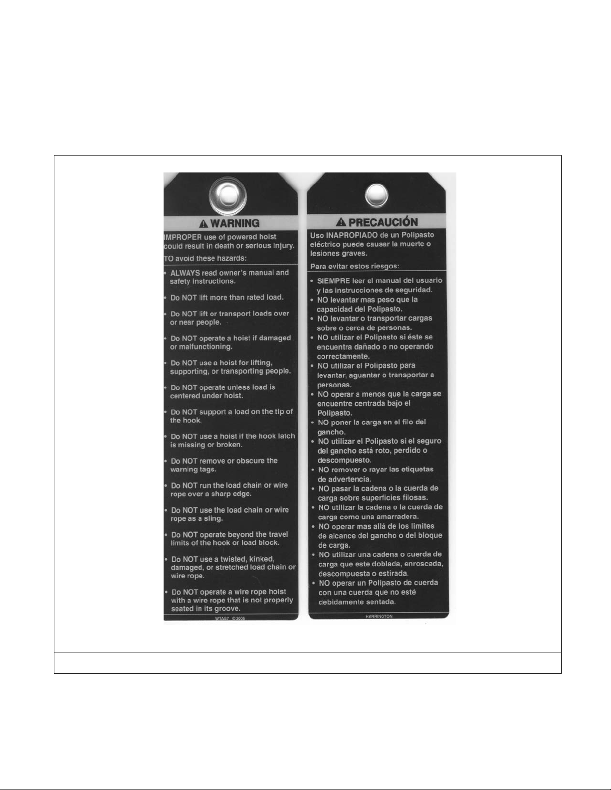
1.2 Warning Tags and Labels
The warning tag illustrated below in Figure 1-1 is supplied with each hoist shipped from the factory. If the tag is
not attached to your hoist (for pendant and manipulator control, the warning tag is attached to the pendant hose;
for the pull cord control, the warning tag is attached to the up cord), order a tag from your dealer and install it.
See parts list in the parts section of this manual. Read and obey all warnings attached to this hoist. Tag is not
shown actual size.
Bilingual Version
Figure 1-1 Warni ng Tag A ttached to Hois t
7
Page 8
2.0 T echni cal Informati on
High Speed Liftin g :
26 to 47 ft/min. (7.9 to 14 .3m/mi n.) with load
Valve Section :
Valve made from al umin um red uce s effe cts of cor rosio n
Compatibility :
Fits existing Harri ngt on trol leys ; use s ex istin g ED l oad c hain
Duty Cycle :
High Duty Cycle
Air Lubrication Requirements :
Minimum of 10 to 15 drops per minute (2-3 cc/min) of oil
Air Supply Pressur e :
60 to 90 psi. (0.4 to 0. 6 M Pa.)
Air Consumption :
19 to 34 CFM (0.54 to 0.96 cubic meters per minut e).
Minimum Supply Ho se Siz e :
3/8 inch (9.5 mm)
Maximum Lift :
131 ft. (39.9 m) for Penda nt and Cord mod els;
13 ft. (4.0 m) for M anip ulator Model.
2.1 Specifications
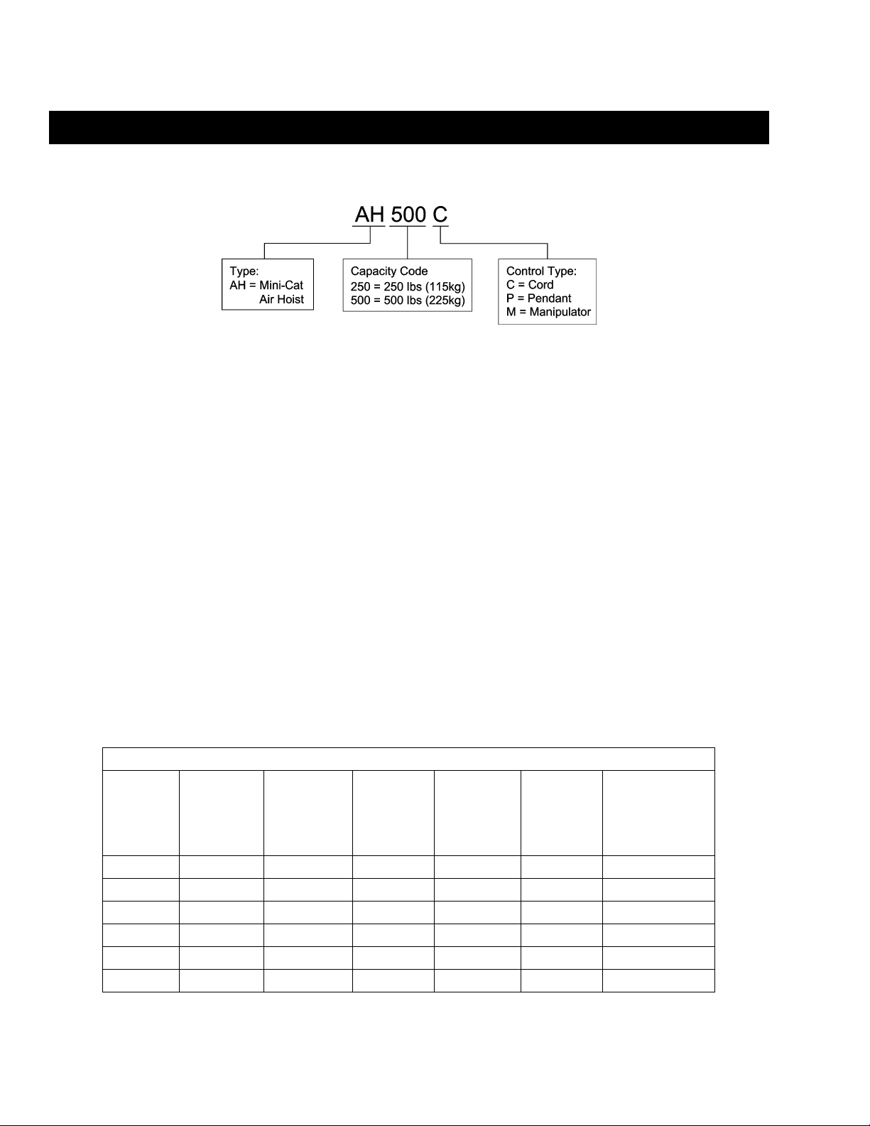
2.1.1 Product Code
2.1.2 Features and General Specifications:
Weight/Size : Light weight and compac t siz e – cord model w ith 10 feet (3.0 m)
of lift weighs 15. 2 lb s. (6.9 kg) .
Motor Brake : R eliable disc bra ke system
Low Noise Levels :
Operating Environ ment : Temperatur e range +14°F to 14 0°F (-10°C to 60°C)
Air Filtration Requ ire ment s : Maximum 5 micron air filter or finer.
Air Inlet Port Size : 3/8 inch NPT
76 dba @ 1 meter when li fting rated loa d
82 dba @ 1 met er w hen low erin g rat ed lo ad
Table 2-1 General Specifications
Capacity
(lbs.)
Product
Code
Headroom
(in)
250 AH250C 12.0 10 4 x 1 15 0.26
500 AH500C 12.0 10 4 x 1 15 0.26
250 AH250P 12.0 10 4 x 1 19 0.49
500 AH500P 12.0 10 4 x 1 19 0.49
250 AH250M 33.0* 6.5 4 x 1 24 0.47
500 AH500M 33.0* 6.5 4 x 1 24 0.47
* Note: Headroom is 45.0 in. with optional 13.0 ft. lift.
Standard
Lift
(ft)
8
Load Chain
Dia. (mm) x
Chain Fall
Lines
Net Weight
with
Standard
Lift
(lbs.)
Weight for
Additional One
Foot of Lift
(lbs.)
Page 9
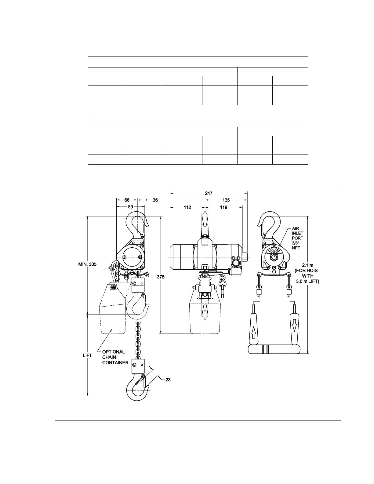
2.2 Speeds, Air Consumptions and Dimensions
Table 2-2 Cord Model Speeds, ft/mi n at 90 ps i*
Capacity
(lbs.)
Product Code
Full Load
250 AH250C 47 (37) 61 (53) 51 (47) 45 (40)
500 AH500C 32 (20) 61 (53) 56 (54) 45 (40)
Table 2-3 Cord Model Air Consumpti on, CFM at 90 psi*
Capacity
(lbs.)
Product Code
Full Load
250 AH250C 32 (24) 34 (27) 30 (24) 28 (23)
500 AH500C 29 (21) 34 (27) 32 (26) 28 (23)
* Values in parentheses for air supply at 60 psi.
UP
No Load
UP DOWN
No Load
DOWN
Full Load
Full Load No Load
No Load
Figure 2-1 Dimensions for Cord Model Mini-Cat Air Hoist (inches)
9
Page 10
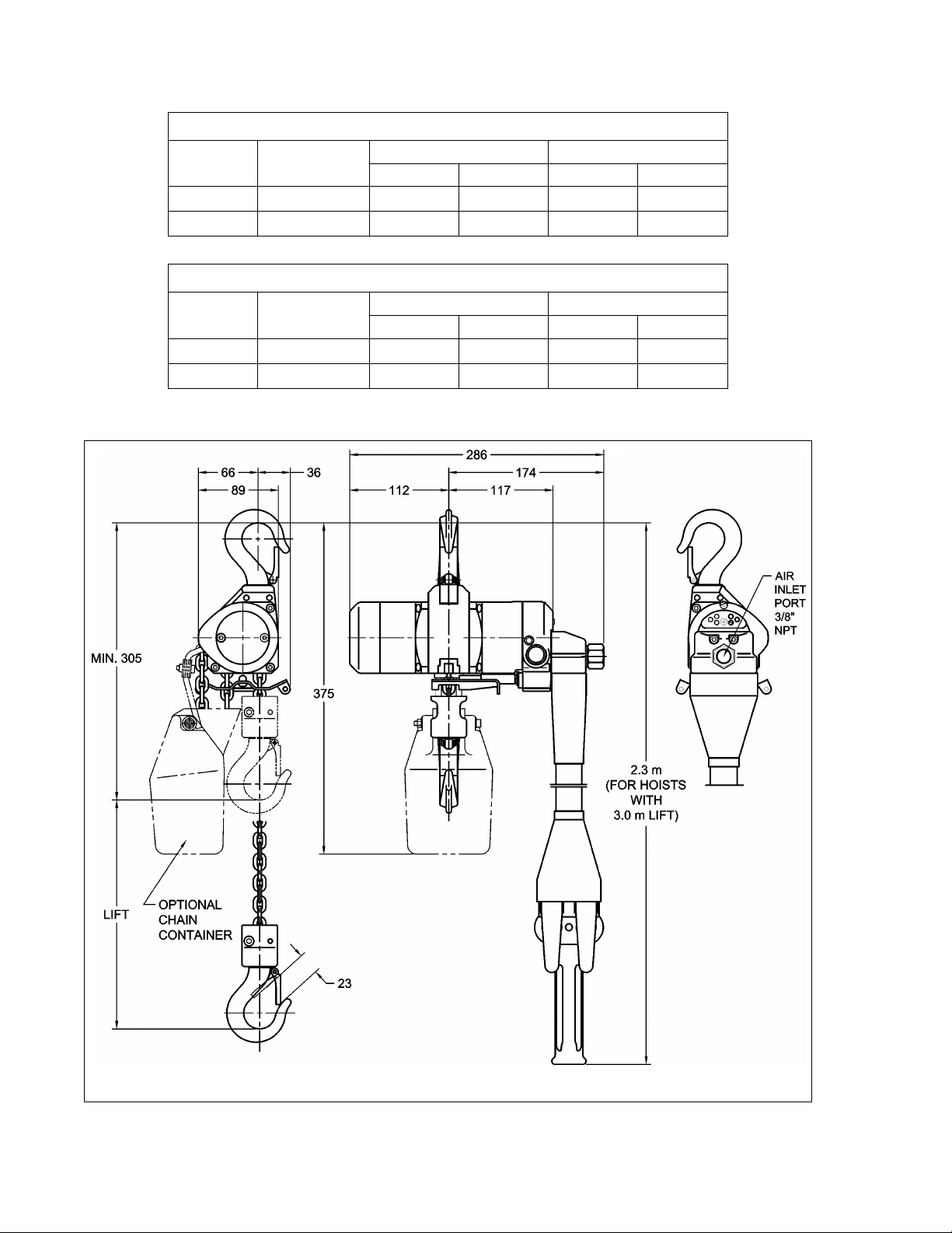
Table 2-4 Pendant Model Spee ds, ft/min at 90 ps i*
Capacity
(lbs.)
Product Code
Full Load
UP
No Load
Full Load
DOWN
No Load
250 AH250P 42 (33) 55 (48) 48 (45) 43 (38)
500 AH500P 29 (18) 55 (48) 53 (51) 43 (38)
Table 2-5 Pendant Model A ir Consumption, CFM at 90 psi*
Capacity
(lbs.)
Product Code
Full Load
UP DOWN
No Load
Full Load No Load
250 AH250P 28 (21) 31 (24) 27 (21) 26 (20)
500 AH500P 26 (19) 31 (24) 28 (22) 26 (20)
* Values in parentheses for air supply at 60 psi.
Figure 2-2 Dimensions fo r Pe nda nt Mo del Mini-Cat Air Hoist (inches)
10
Page 11
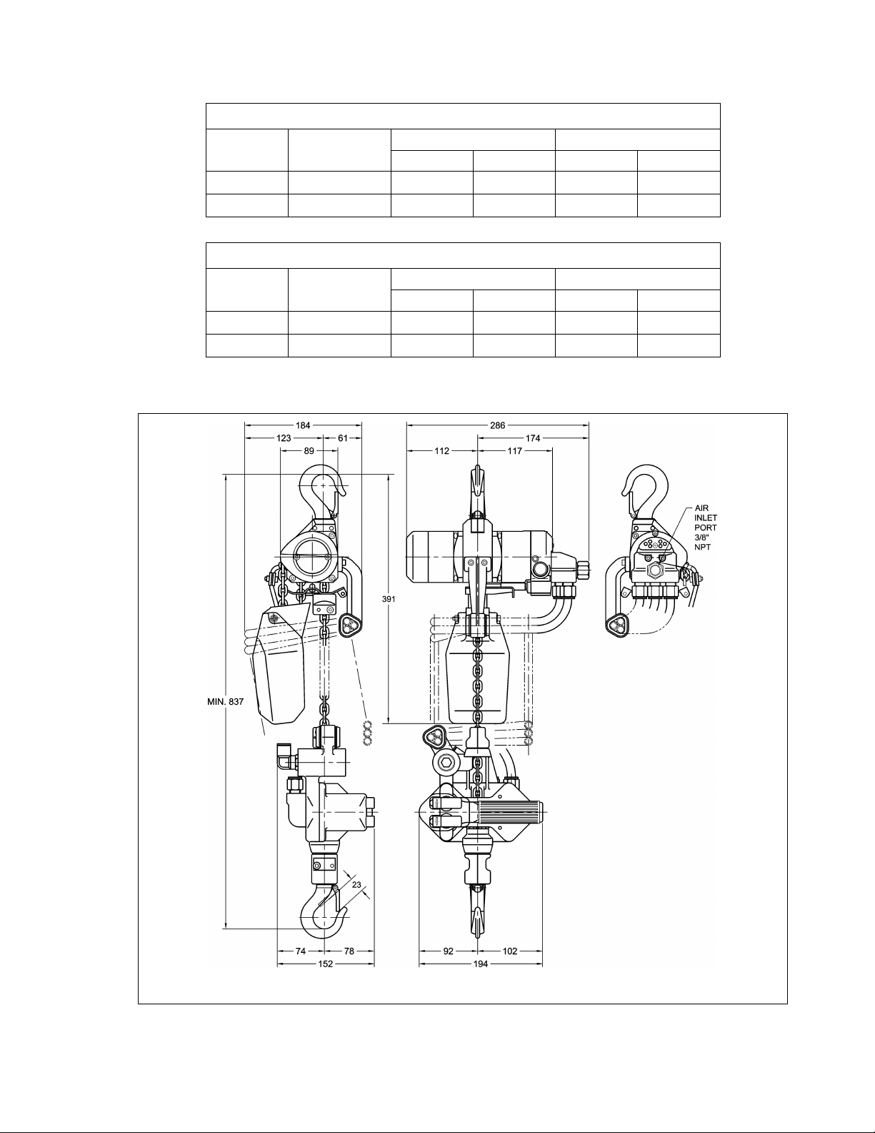
Table 2-6 Manipulator Model S peeds, ft/min at 90 psi*
Capacity
(lbs.)
Product Code
Full Load
UP
No Load
Full Load
DOWN
No Load
250 AH250M 41 (32) 54 (47) 47 (44) 42 (37)
500 AH500M 29 (18) 54 (47) 53 (50) 42 (37)
Table 2-7 Manipulator Model Air Consumption, CFM at 90 psi*
Capacity
(lbs.)
Product Code
Full Load No Load Full Load No Load
UP DOWN
250 AH250M 28 (21) 31 (24) 27 (21) 26 (20)
500 AH500M 26 (19) 31 (24) 28 (22) 26 (20)
* Values in parentheses for air supply at 60 psi.
Figure 2-3 Dimensions for Manipula tor Mod el Mini-Cat Air Hoist (inches)
11
Page 12
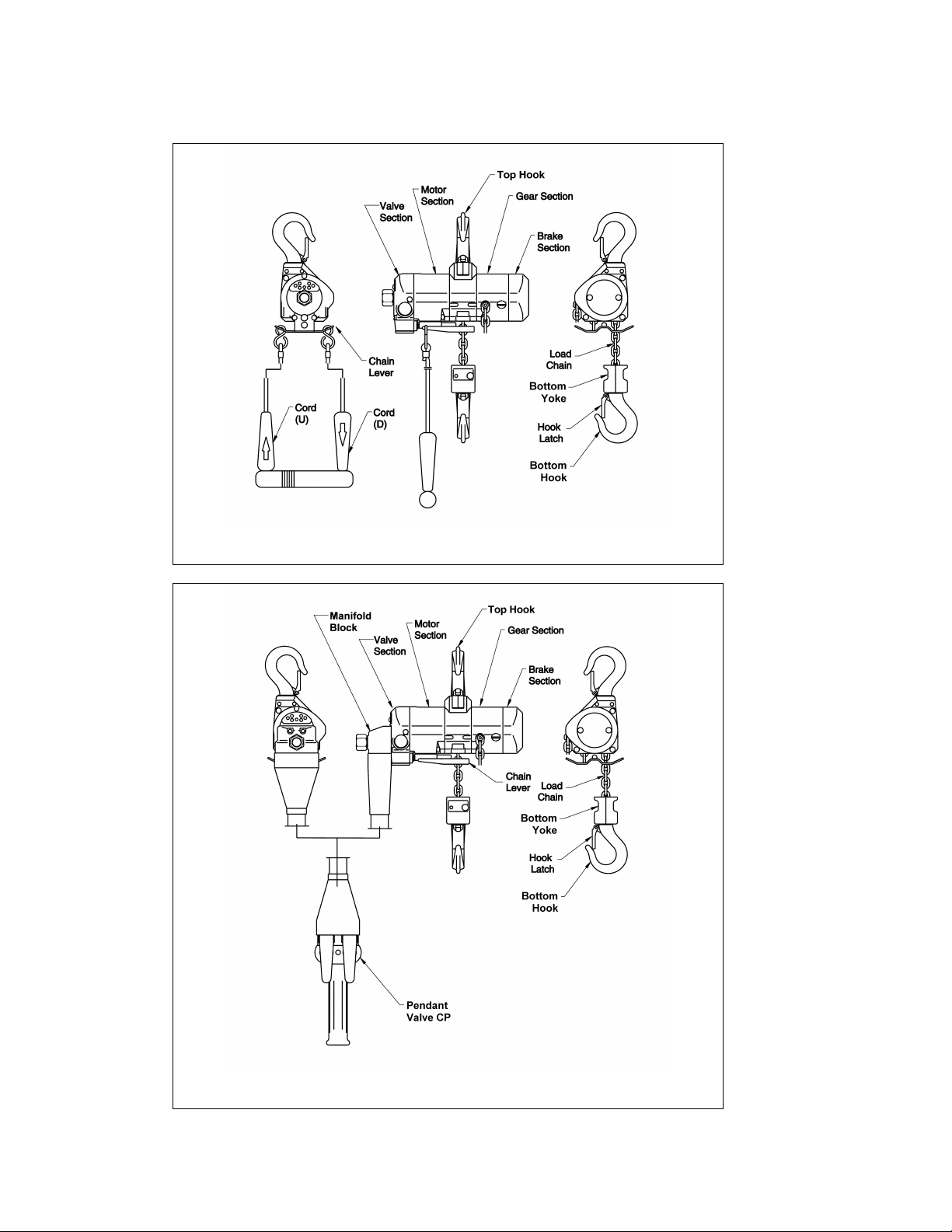
2.3 Part Names
Figure 2-4 AH250C and AH500C Cord Model Part Names
Figure 2-5 AH250P and AH500P Pendant Model Part Names
12
Page 13
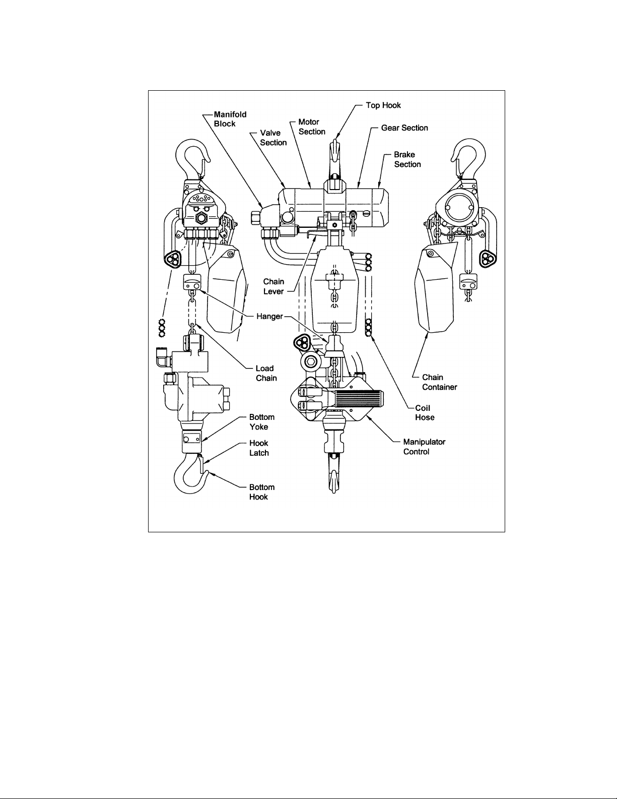
Figure 2-6 AH250M and AH500M Manipulator Model Part Names
13
Page 14

3.0 Pre-operatio nal Procedures
3.1 Air Supply System Requirements
3.1.1
air hoist with required pressure and flow. Otherwise the hoist may operate poorly or may fail to operate.
See Section 3.2.
3.1.2
supply is the primary source of lubrication to the hoist. Therefore, a dedicated air supply lubricator must
be used with the hoist. Refer to Section 3.3.
3.1.3
ensure its proper operation. The air must be clean and free of debris such as dirt and rust. Refer to
Section 3.4 for filtration requirements. The air must also be dry; free of moisture and water. Refer to
Section 3.5.
Pressure and Flow - Verify that the air supply system has capacity to supply your
Lubrication - The hoist requires lubrication for proper operation. The oil in the air
Air Quality - Good air quality is essential to prevent damage to your hoist and to
3.2 Air Supply Capacity and Regulation
3.2.1 Capacity - The air supply system must be capable of delivering the required airflow (cfm or m³/min) to
the hoist inlet port. Without the required airflow the hoist will not operate properly or may not operate at
all. See Section 2.0 for your hoist's air consumption requirements. In determining if your system is
capable of supplying the required airflow, consider the following:
Capacity of compressor(s) and tank
Other air consuming equipment
Flow restrictions such as pipes, hoses, valves and fittings
Inadequate capacity will cause a significant drop in pressure when the hoist is operated, and could
cause poor performance or failure to operate.
3.2.2 Regulation - The hoist requires a constant supply of air at a pressure of between 60 and 90 psi (0.4
MPa and 0.6 MPa). If the air supply is not regulated or is regulated at a pressure greater than 90 psi
(0.6 MPa), then a regulator must be used
lubricator in the air supply to the hoist.
3.3 Lubrication
3.3.1
as follows:
1) Best location - At the hoist inlet. In this case the lubricator can be either the mist type or drop
type.
2) Second best location - No more than 15 feet (4.5 meters) away from the hoist, at the same
elevation or above the hoist inlet. In this case the mist type lubricator must be used.
3) Third best location - No more than 15 feet (4.5 meters) away below the hoist. In this case the
mist type lubricator must be used.
3.3.2
minute (2 to 3 cc/minute). The hoist’s exhaust will emit a fine oil mist when properly lubricated. Refer
to Section 6.1 for type of oil to use.
. The regulator may be located anywhere up-line of the
The hoist must be supplied with its own lubricator. The lubricator must be located
The lubricator must be set to deliver the equivalent of 10 to 15 drops of oil per
14
Page 15
3.4 Filtration
3.4.1
microns in size. Therefore, the hoist must have a 5 micron filter
upstream of the lubricator.
3.4.2 The filter servicing the hoist can also service other hoists and air consuming equipment. In this case,
the air filter must be in sized for the total air consumption of the equipment it is servicing.
The air entering the hoist inlet must not contain any particulate greater than 5
3.5 Air Dryer
3.5.1
system to ensure that dry air
this moisture will cause corrosion on internal hoist components during periods when the hoist is idle
leading to hoist malfunction.
To prevent corrosion and hoist malfunction, employ an air dryer in the air supply
3.6 Piping, Hoses And Fittings
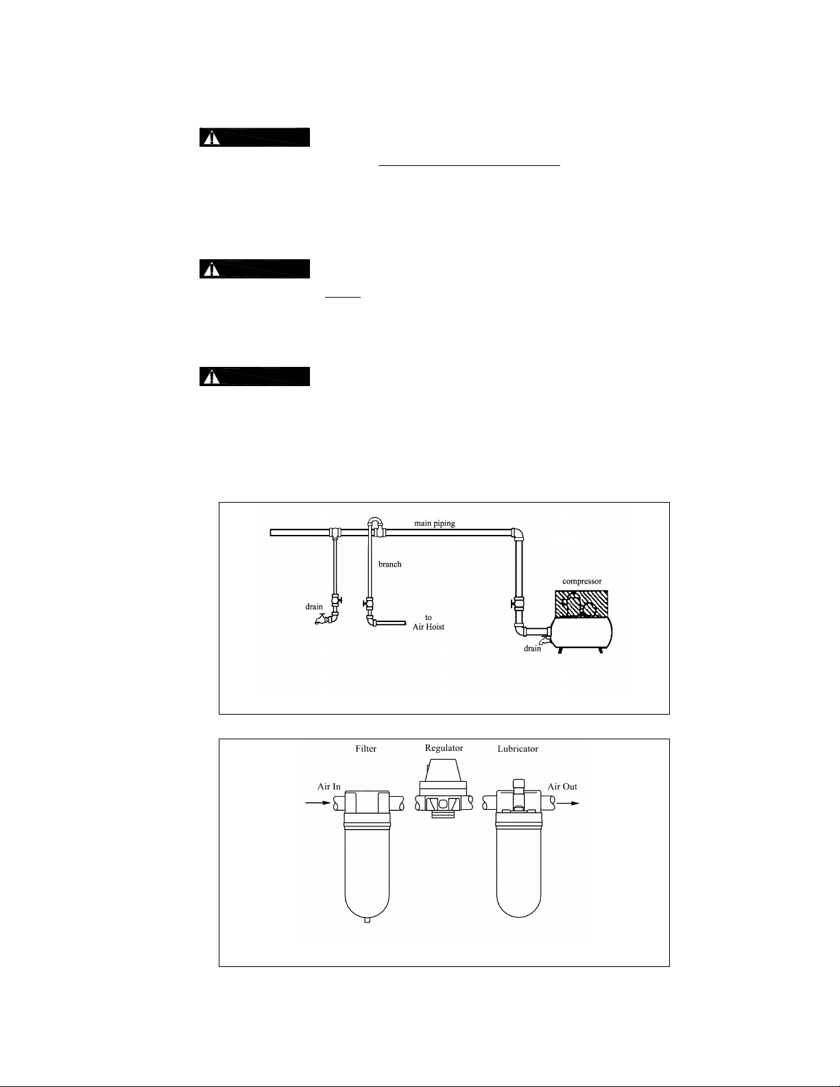
3.6.1
Since moisture tends to accumulate in compressed air systems, corrosion may result if the system is
not periodically drained.
Arrange for a drain in the air supply piping at the lowest point in the piping, and
Periodically drain the system to remove moisture/water from the system and to prevent corrosion.
Filter, regulator (if equipped), and lubricator must be arranged in the order shown in Figure 3-2.
System Configuration - The system should be configured as shown in Figure 3-1.
in its air supply. The filter must be
is supplied to the hoist. If there is moisture in the air supplied to the hoist,
Figure 3-1 Diagram of Air Supply Configuration (Typical)
Figure 3-2 Typical Air Supply Filter, Regulator and Lubricator.
15
Page 16
3.6.2
3.6.3
Supply line inside diameter - Pipes and hoses should be sized to accommodate
the hoist’s airflow requirements. The inside diameter for the pipe section feeding the hoist should be
12.7mm (½”) or larger and for air supply hose the inside diameter should be 9.5mm (3/8”) inch or larger.
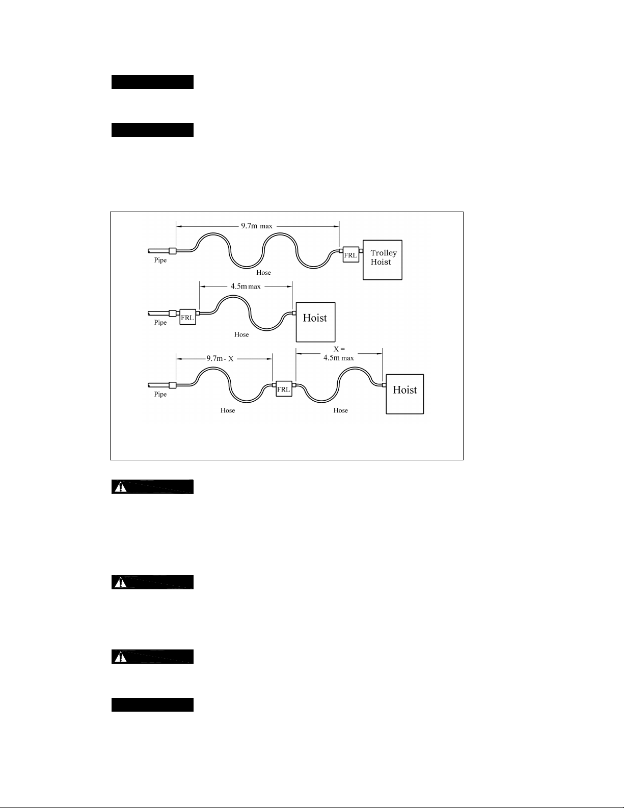
Hoses - The connection from the air supply system piping to the hoist must be
made with a flexible pressure hose. Due to normal line losses in air supply lines:
Do not use hose smaller than specified in Section 3.6.2, and
Limit the length of the hose to that specified in Figure 3-3.
If your application exceeds these requirements consult factory.
Figure 3-3 Typical Arrangements of Filter, Regulator and Lubricator and
3.6.4
include:
When connecting air supply components, remove all dirt or debris from the connecting surfaces of
the hoses, pipes, fittings, or threaded fasteners to prevent contaminants from entering the hoist.
Keep airflow restrictions such as quick disconnect fittings, bends, elbows, and adapters to a
minimum.
3.6.5
purging procedures to prevent contaminants or moisture from entering the hoist.
3.7 Mounting Location
3.7.1
are adequate to support the hoist and its loads. If necessary consult a professional that is qualified to
evaluate the adequacy of the suspension location and its supporting structure.
3.7.2
Maximum Air Supply Hose Lengths
Fittings - Important considerations regarding fittings in the hoist’s air supply
Before connecting the hoist to its air supply line, perform the proper draining and
Prior to mounting the hoist ensure that the suspension and it supporting structure
See Section 7.6 for outdoor installation considerations.
16
Page 17
3.8 Connecting Hoist to Air Supply
3.8.1
OF COMPRESSED AIR TO THE HOIST, AND IN THE CONNECTIONS BETWEEN COMPONENTS.
3.8.2 Shut off the air supply and stop the airflow completely. Lock out and tag out in accordance with ANSI
Z244.1 “Personnel Protection -Lockout/Tagout of Energy Sources”.
HAZARDOUS AIR PRESSURE IS PRESENT IN THE HOIST, IN THE SUPPLY
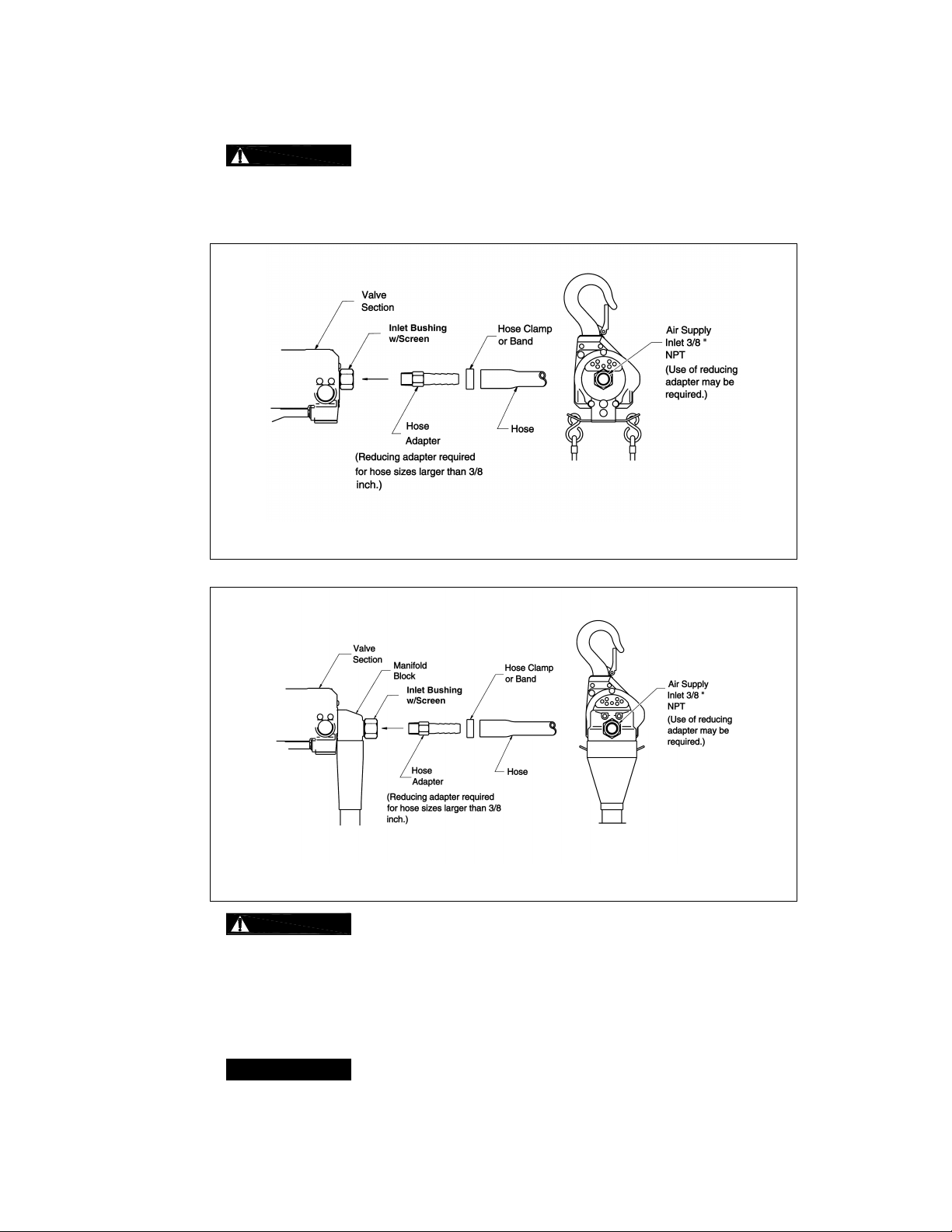
Figure 3-4 Cord Model Connection to Hoist
Figure 3-5 Pendant and Manipulator Models Connection to Hoist
3.8.3
clear any debris and water.
3.8.4 Apply approximately 10-15 drops (2 to 3 cc/minute) of turbine oil (see approved lubricant under Section
6.0 Lubricants) into the hose before attaching to the hoist.
3.8.5 Make connections to air supply; reference Figure 3-4 or 3-5. Use a reducing adapter at the hoist valve
section for hose sizes larger than 9.5mm (3/8”).
3.8.6
the hoist first (Section 3.9) followed be connecting the air supply.
Before connecting the air supply hose to the hoist, always purge the air hose to
Where conditions dictate, the installation sequence can be reversed by mounting
17
Page 18

3.9 Mounting the Hoist
3.9.1 Mini Trolley - Follow instructions below to install the trolley. Refer to Figure 3-6.
1) Remove the Top Hook Complete Set from the hoist and install the Suspender.
2) Refer to Table 3-1 for placement of Adjusting Spacers for the flange width “B” of the traversing
beam. The position of spacers differs with flange width. If the beam flange width is not listed in
Table 3-1, use the next size smaller and make adjustments in accordance with step 3. Use all 32
adjusting spacers provided.
3) Refer to Figure 3-6 and assemble the trolley Frames, Adjusting Spacers and Socket Bolts onto the
Suspender. Install and hand tighten the plain Nuts on the Socket Bolts. Verify that dimension “A”
is approximately 0.12 - 0.16 in (3-4mm) greater than “B” (flange width). If "A" does not fall within
the specified range, move spacers from inner to outer or from outer to inner as necessary to obtain
the proper "A" dimension, irrespective of the numbers in Table 3-1.
4) Install the trolley and hoist onto traversing beam using one of the following 2 methods:
Preferred Method – Sliding the trolley connected with hoist onto the traversing beam from the
beam end is the most convenient and recommended method. If the trolley can be mounted
from the end of the beam then: Remove the trolley end-stop from the beam and set the trolley
on the beam from the end. Securely re-install the trolley end stop on the beam.
Optional Method – If the trolley cannot be mounted from the end of the beam, loosen the plain
Nuts and spread the trolley Frames. Lift the trolley and hoist onto the beam from below. Push
the trolley frames together and hand tighten the plain Nuts.
5) Check for contact between all four trolley wheels and the rail surface. Shift the Trolley Frame until
all trolley wheels rest on the rail surface. Tighten the plain Nuts and install the two U-Nuts onto the
Socket Bolts tighten against the plain Nuts. Install the Split Pins onto the Socket Bolts and bend
securely.
Incorrect number of adjusting spacers may cause the trolley to not move or to
6)
drop. To avoid these hazards, always make sure to use all 32 spacers and confirm that A - B =
0.12 - 0.16 in (3-4mm).
7)
To prevent the trolley from dropping, firmly fasten the Socket Bolt, Nut and U-
Nut. Insert split pin and bend the ends 90 degrees or more.
Inside right
frame
Outside right
frame
Rail Width mm (in)
Table 3-1 Number of Spacers
Outside left
frame
Inside left
frame
50.8 (2) 8 8 6 8
58.7 (2 5/16) 6 9 8 7
63.5 (2 ½) 6 10 8 6
68.3 (2 11/16) 5 10 9 6
71.4 (2 13/16) 5 11 9 5
76.2 (3) 4 12 10 4
82.6 (3 ¼) 3 13 11 3
84.1 (3 5/16) 3 13 11 3
90.5 (3 9/16) 2 14 12 2
93.7 (3 11/16) 1 14 13 2
98.4 (3 7/8) 0 15 14 1
100 (3 15/16) 0 16 14 0
18
Page 19

Figure 3-6 Diagram for Mini Trolley Installation
3.9.2 Manual Trolley - Follow instructions in Owner’s Manual provided with the trolley.
3.9.3 Motorized Trolley - Follow instructions in Owner’s Manual provided with the trolley.
3.9.4 Hook Mounted to a Fixed Location - Attach the hoist’s top hook to the fixed suspension point.
3.9.5
that the hook’s latch is engaged.
Ensure that the fixed suspension point rests on the center of the hook’s saddle and
3.10 Optional Chain Container
3.10.1 Follow instructions below to install the optional chain container. Refer to Figure 3-7.
1) Insert the Bucket Arm Assembly into the notched openings on the Wheel Housing.
2) Loosely attach the Arm Holders to the Bucket Arm Assembly with the Bolt, Washers and U-Nut
provided.
3) Attach the Chain Container onto the Bucket Arm Assembly with the Socket Bolt BP, U-Nut and
Split Pin. Make Sure to Securely bent the Split Pin.
4) Tighten the Bolt and U-Nut on the Arm Holders.
5) Feed the Chain into the Chain Container beginning with the no-load end. Take care to avoid
twisting or tangling the Chain.
6)
fasteners/hardware are missing.
Do not use the Chain Container if any parts are damaged or if any
19
Page 20

3.11 Non-Stationary Application
Figure 3-7 Chain Container Installation
3.11.1 For applications such as rental fleets or construction sites where the hoist is moved from place-to-place,
a filter and lubricator are still required. Consult factory for recommended methods.
3.11.2 Connections and fittings must be kept clean and care taken to prevent dirt, debris and moisture from
entering the hoist.
3.11.3 Recommended practice for removing the hoist from an installation:
1) Run the hoist briefly with well lubricated air
2) Shut off the air supply to the hoist, bleed off any pressure in the system then disconnect the air
supply line.
3) Inject a small quantity (approximately 20 drops) of tubine oil (see Section 6.0) into the hoist’s inlet
port
4) Plug the inlet port
3.12 Manipulator Right or Left Hand Operation
3.12.1 Follow instructions below to configure for right or left-hand operation. Refer to Figure 3-8.
1)
SUPPLY OF COMPRESSED AIR TO THE HOIST, AND IN THE CONNECTIONS BETWEEN
COMPONENTS. Shut off the air supply and stop the airflow completely. Bleed off any pressure in
the system. Lock out and tag out in accordance with ANSI Z244.1 “Personnel Protection Lockout/Tagout of Energy Sources”.
2) Remove the 6 Button Head Screws located on the back side of the Manipulator control then
remove the Throttle Valve Complete.
HAZARDOUS AIR PRESSURE IS PRESENT IN THE HOIST, IN THE
3) Make sure the 8 O-Rings and 2 Spring Pins are correctly positioned, then rotate the Throttle Valve
Complete 180 degrees and re-install.
4) Re-install and tighten the 6 Button Head Screws
5) Re-connect or turn on the air supply and check for leaks and proper operation.
20
Page 21

Right-Hand Left-Hand
Figure 3-8 Converting Manipulator Model Between Right and Left-Hand Operation.
3.13 Manipulator Model’s Bottom Hook Position
3.13.1 The Bottom Hook can be extended below the manipulator control to allow for easier load attachment
and operation as required by the application. Follow instructions below. Refer to Figure 3-9.
1) Run the hoist in the down direction until there is a sufficient amount of Load Chain below the hoist.
2)
SUPPLY OF COMPRESSED AIR TO THE HOIST, AND IN THE CONNECTIONS BETWEEN
COMPONENTS. Shut off the air supply and stop the airflow completely. Bleed off any pressure in
the system. Lock out and tag out in accordance with ANSI Z244.1 “Personnel Protection Lockout/Tagout of Energy Sources”.
3) Remove both Hangers from the Load Chain.
4) Slide the Manipulator Control up the Load Chain to the desired position then reinstall the bottom
Hanger onto the Load Chain.
5) Refer to the minimum dimensions between the hangers shown in Figure 3-9. Measure up from the
bottom Hanger and reinstall the top Hanger onto the Load Chain.
HAZARDOUS AIR PRESSURE IS PRESENT IN THE HOIST, IN THE
21
Page 22

Standard Alternate/Extended
Figure 3-9 Manipulator Model’s Bottom Hook Position
3.14 Preoperation Checks and Trial Operation
3.14.1
other lifting attachments before use. Inspect all load suspension members for damage prior to use and
replace or repair all damaged parts.
3.14.2
reference see Figure 7-3.
3.14.3 Measure and record the “K” and “U” dimensions for the top and bottom hooks. See Table 5-6 under
Section 5, “Inspection”.
3.14.4 Record the hoist Code and Serial Number (from the name plate on the hoist – see Figure 10-1) in the
space provided on the cover of this manual.
3.14.5 Ensure that the hoist is properly installed to either a fixed point, or trolley, whichever applies.
Confirm the adequacy of the rated capacity for all slings, chains, wire ropes and all
Verify that the no-load end of the load chain is attached to the hoist body. For
22
Page 23

3.14.6 If hoist is installed on a trolley, ensure that
trolley is properly installed on the beam, and
stops for the trolley are correctly positioned and securely installed on the beam.
3.14.7 Ensure that all nuts, bolts and split (cotter) pins are sufficiently fastened.
3.14.8 For Pendant model hoists, ensure that the Pendant Hoses/Tubes are properly attached to the hoist and
Pendant Valve CP. See Section 7.3.
3.14.9 For Manipulator model hoists, ensure that the Coil Hose is properly attached to the hoist and
Manipulator Control. See Section 7.3.
3.14.10
Check Air Supply - Check air supply before everyday use. Ensure proper air
quality and air pressure.
3.14.11
Check the lubricator for proper function and adequate oil level.
3.14.12 Confirm proper operation.
Before operating read and become familiar with Section 4 - Operation.
Before operating ensure that the hoist (and trolley) meets the Inspection, Testing and Maintenance
requirements of ANSI/ASME B30.16.
Before operating ensure that nothing will interfere with the full range of the hoist’s (and trolley’s)
operation.
3.14.13 Proceed with trial operation to confirm proper operation.
Initially operate slowly under no load in both directions.
Perform inspections per Section 5.3, “Frequent Inspections”.
Make sure hook travel is in the same direction as shown on controls.
23
Page 24

4.0 Operation
4.1 Introduction
DO NOT WALK UNDER A SUSPENDED LOAD
HOIST OPERAT ORS SHALL BE REQUIRED TO READ THE OPER ATION SECTION O F THIS MANUAL, THE
WARNINGS CONTAINED IN THIS MANUAL, INSTRUCTION AND WARNING LABELS ON THE HOIST OR
LIFTING SYSTEM , AND THE OPERATION SEC TIONS OF ANSI/ASM E B30.16 and ANSI/ASM E B30.10. THE
OPERATOR SHALL ALSO BE REQUIRED TO BE FAMILIAR WITH THE HOIST AND HOIST CONTROLS
BEFORE BEING AUTHORIZED TO OPERATE THE HOIST OR LIFTING SYSTEM.
HOIST OPERATORS SHOULD BE TRAINED IN PROPER RIGGING PROCEDURES FOR THE ATTACHMENT
OF LOADS TO THE HOIST HOOK.
HOIST OPERATORS SHOULD BE TRAINED TO BE AWARE OF POTENTIAL MALFUNCTIONS OF THE
EQUIPMENT T HAT REQUIRE ADJUST MENT OR REP AIR, AND TO BE IN STRUCTED TO STOP OPERAT ION
IF SUCH MALFUN CTIONS OCCUR, AND TO IMMED IATELY AD VISE TH EIR SUP ERVISOR SO CORRECTIVE
ACTION CAN BE TAKEN.
HOIST OPERATORS SHOULD HAVE NORMAL DEPT H PERCEPTION, FIELD OF VISION, REACTION TIME,
MANUAL DEXTERITY, AND COORDINATION.
HOIST OPERATORS SHOULD NOT HAVE A HISTORY OF OR BE PRONE TO SEIZURES, LOSS OF
PHYSICAL CONTROL, PHYSICAL DEFECTS, OR EMOTIONAL INSTABILITY THAT COULD RESULT IN
ACTIONS OF THE OPERATOR BEING A HAZARD TO THE OPERATOR OR TO OTHERS.
HOIST OPERATORS SHOULD NOT OPERATE A HOIST OR LIFTING SYSTEM WHEN UNDER THE
INFLUENCE OF ALCOHOL, DRUGS, OR MEDICATION.
OVERHEAD HOISTS ARE INTENDED ONLY FOR VERT ICAL LIFTING SERVICE OF FREELY SUSPENDED
UNGUIDED LOADS. DO NOT
ARE NOT FREELY SUSPENDED, OR LOADS THAT ARE GUIDED.
USE HOI ST FOR LOADS T HAT ARE NOT LI FTED VERTIC ALLY, LOADS T HAT
• Read ANSI/ASME B30.16 and ANSI/ASME B30.10.
• Read the hoist manufacturer’s Operating and Maintenance Instructions.
• Read all labels attached to equipment.
24
Page 25

The operation of an overhead hoist involves more than activating the hoist’s controls. Per the ANSI/ASME B30
standards, the use of an overhead hoist is subject to certain hazards that cannot be mitigated by engineered features,
but only by the exercise of intelligence, care, common sense, and experience in anticipating the effects and results of
activating the hoist’s controls. Use this guidance in conjunction with other warnings, cautions, and notices in this manual
to govern the operation and use of your overhead hoist.
4.2 Shall’s and Shall Not’s for Operation
Improper operation of a hoist can create a potentially hazardous
situation which, if not avoided, could result in death
and substantial property damage. To avoi d such a poten tially
hazardous situation THE OPERATOR SHALL:
• NOT
• NOT
• NOT
• NOT
• NOT
• NOT
• NOT
• NOT
• NOT
• NOT
• NOT
• NOT
• NOT
• NOT
• NOT operate hoist with missing/damaged chain
lift more than rated load for the hoist.
operate unless load is centered under hoist.
use damaged hoist or hoist that is not working
properly.
use hoist with twisted, kinked, damaged, or
worn chain.
use the hoist to lift, support, or transport
people.
lift loads over people.
apply load unless load chain is properly
seated in the load sheave.
use the hoist in such a way that could result in
shock or impact loads being applied to the hoist.
attem pt to lengthen the load chain or repair
damaged load chain.
operate hoist when it is restricted from forming
a straight line from hook to hook in the direc tion of
loading.
use load chain as a sling or wrap load chain
around load.
appl y the load to the tip of the hook or to the
hook latch.
apply load if binding prevents equal loading
on all load supporting chains.
operate beyond the limits of the load chain
travel.
components.
• NOT leave load suppor ted by the hoist unattended
unless specific precautions have been taken.
• NOT
electrical or welding ground.
• NOT
live welding electrode.
• NOT
• Be familiar with operating controls, procedures, and
warnings.
• Make sure the unit is securely attached to a
suitable support before applying load.
• Make sure load slings or other approved single
attachments are properl y sized, rigged, and seate d
in the hook saddle.
• Take up slack carefully - make sure load is
balanced and load-holding action is secure bef ore
continuing.
• Make sure all persons st ay clear of the supported
load.
• Protect the hoist’s load chai n from weld splatter or
other damaging contaminants.
• Report Malfunctions or unusual performances
(including unusual noises) of the hois t and remove
the hoist from service until the malfunction or
unusual performance is resolved.
• Make sure hoist limit switches function properly.
• Warn personnel before lifting or moving a load.
• Warn personnel of an approaching load.
or serious i njury,
allow the chain, or hook to be used as an
allow the chain, or hook to be touched by a
remove or obscure the warnings on the hoist.
25
Page 26

Improper operation of a hoist can create a poten tially haz ardous
situation which, if not avoided, could result in minor
injury
, or property damage. To avoid such a potential ly haz ardous
situation THE OPERATOR SHALL:
or moderate
• Maintain a firm footing or be otherwise secured
when operating the hoist.
• Check brake funct ion by tensioning the hoist prior
to each lift operation.
• Use hook latches. Latches are to retain slings,
chains, etc. under slack conditions only.
• Make sure the hook latches are closed and not
supporting any parts of the load.
• Make sure the load is free to move and will clear all
obstructions.
• Avoid swinging the load or hook.
• Make sure hook travel is in the sam e direction as
shown on controls.
• Inspect the hoist regularly, replace damaged or
worn parts, and keep appropriate records of
maintenance.
4.3 Hoist Controls
4.3.1 Cord Control - When using a hoist with cord control, pull down on the appropriate colored cord to raise
or lower the load. White indicates the raise control and red indicates lowering control. Release the
cords to stop the hoist. Refer to Figure 4-1 below.
• Use the hoist manufacturer’s recommended parts
when repairing the unit.
• Lubricate load chain per hoist manufacturer’s
recommendations.
• NOT use limit switches as routin e operating stops.
They are emergency devices only.
• NOT allow your attention to be diverted from
operating the hoist.
• NOT allow the hoist to be subjected to sharp
contact with other hoists, structures, or objects
through misuse.
• NOT adjust or repair the hoist unless qualified to
perform such adjustments or repairs.
4.3.2 Pendant and Manipulator Controls – When using a hoist with pendant or manipulator control, depress
the “up” lever to raise the load or the “down” lever to lower the load as shown in Figure 4-1 below. To
stop motion release the levers.
Figure 4-1 Cord Control, Pendant Control and Manipulator Control
26
Page 27

4.4 Controlling Hoist Speed
4.4.1 For the cord control, adjust the speed by varying the amount of pull on the cord. Refer to Figure 4-2.
Figure 4-2 Cord, Pendant and Manipulator Control Speed Adjustment
4.4.2 For the pendant or manipulator control, adjust the speed by varying the amount the lever is depressed.
As shown in Figure 4-2, by depressing the lever slightly, you will be able to control the hoist’s motions
slowly and with more precision. By the depressing the lever further, the speed of the hoist will be
increased until the lever is fully depressed.
27
Page 28

5.0 Inspection
5.1 General
5.1.1 The inspection procedure herein is based on ANSI/ASME B30.16. The following definitions are from
ANSI/ASME B30.16 and pertain to the inspection procedure below.
Designated Person - a person selected or assigned as being competent to perform the specific
Qualified Person - a person who, by possession of a recognized degree or certificate of
Normal Service - that distributed service which involves operation with randomly distributed loads
Heavy Service - that service which involves operation within the rated load limit which exceeds
Severe Service - that service which involves normal or heavy service with abnormal operating
duties to which he/she is assigned.
professional standing, or who, by extensive knowledge, training, and experience, has successfully
demonstrated the ability to solve or resolve problems relating to the subject matter and work.
within the rated load limit, or uniform loads less than 65% of rated load for not more than 25% of
the time.
normal service.
conditions.
5.2 Inspection Classification
5.2.1 Initial Inspection - prior to initial use, all new, altered, or modified hoists shall be inspected by a
designated person to ensure compliance with the applicable provisions of this manual.
5.2.2 Inspection Classification - the inspection procedure for hoists in regular service is divided into two
general classifications based upon the intervals at which inspection should be performed. The intervals
in turn are dependent upon the nature of the critical components of the hoist and the degree of their
exposure to wear, deterioration, or malfunction. The two general classifications are herein designated
as FREQUENT and PERIODIC, with respective intervals between inspections as defined below.
5.2.3 FREQUENT Inspection - visual examinations by the operator or other designated personnel with
intervals per the following criteria:
Normal service - monthly
Heavy service - weekly to monthly
Severe service - daily to weekly
Special or infrequent service - as recommended by a qualified person before and after each
occurrence.
5.2.4 PERIODIC Inspection - visual inspection by a designated person with intervals per the following criteria:
Normal service - yearly
Heavy service - semiannually
Severe service - quarterly
Special or infrequent service - as recommended by a qualified person before the first such
occurrence and as directed by the qualified person for any subsequent occurrences.
28
Page 29

5.3 Frequent Inspection
5.3.1 Inspections should be made on a FREQUENT basis in accordance with Table 5-1, “Frequent
Inspection.” Included in these FREQUENT Inspections are observations made during operation for
any defects or damage that might appear between Periodic Inspections. Evaluation and resolution of
the results of FREQUENT Inspections shall be made by a designated person such that the hoist is
maintained in safe working condition.
All functional operating mechanisms for maladjustment and unusual sounds.
Operation of limit switch and associated components
Hoist braking system for proper operation
Hooks in accordance with ANSI/ASME B30.10
Hook latch operation
Load chain in accordance with Section 5.7
Air valves and components for leakage or damage
Table 5-1 Frequent Inspection
5.4 Periodic Insp ection
5.4.1 Inspections should be made on a PERIODIC basis in accordance with Table 5-2, “Periodic Inspection.”
Evaluation and resolution of the results of PERIODIC Inspections shall be made by a designated
person such that the hoist is maintained in safe working condition.
5.4.2 For inspections where load suspension parts of the hoist are disassembled, a load test per ANSI/ASME
B30.16 must be performed on the hoist after it is re-assembled and prior to its return to service.
Requirements of frequent inspection.
Evidence of loose bolts, nuts, or rivets.
Evidence of worn, corroded, cracked, or distorted parts such as load blocks,
suspension housing, chain attachments, clevises, yokes, suspension bolts, shafts,
gears, bearings and pins.
Evidence of damage to hook retaining nuts or collars and pins, and welds or rivets
used to secure the retaining members.
Evidence of damage or excessive wear of load sheaves.
Evidence of excessive wear on motor vanes or on load brake.
Evidence of damage of supporting structure or trolley, if used.
Function labels on pendant control stations for legibility.
Table 5-2 Periodic Inspection
Warning label properly attached to the hoist and legible (see Section 1.2).
End connections of load chain.
29
Page 30

5.5 Occasion ally Used Hoists
5.5.1 Hoists that are used infrequently shall be inspected as follows prior to placing in service:
Hoist Idle More Than 1 Month, Less Than 1 Year: Inspect per FREQUENT Inspection criteria of
Section 5.3 above.
Hoist Idle More Than 1 Year: Inspect per PERIODIC Inspection criteria of Section 5.4 above.
5.6 Inspection Records
5.6.1 Dated inspection reports and records should be maintained at time intervals corresponding to those
that apply for the hoist’s PERIODIC interval per Section 5.4 above. These records should be stored
where they are available to personnel involved with the inspection, maintenance, or operation of the
hoist.
5.6.2 A long range chain inspection program should be established and should include records of
examination of chains removed from service so a relationship can be established between visual
observation and actual condition of the chain.
5.7 Inspection Methods and Criteria
5.7.1 This section covers the inspection of specific items. The list of items in this section is based on those
listed in ANSI/ASME B30.16 for the Frequent and Periodic Inspection. In accordance with ANSI/ASME
B30.16, these inspections are not intended to involve disassembly of the hoist. Rather, disassembly for
further inspection would be required if frequent or periodic inspection results so indicate. Such
disassembly and further inspection should only be performed by a qualified person trained in the
disassembly and re-assembly of the hoist.
Table 5-3 Hoist Inspection Methods and C riter ia
Item Method Criteria Action
Functional operating
mechanisms.
Visual, Auditory Mechanisms should be properly adjusted and
should not produce unusual sounds when
operated.
Limit Switch Function Proper operation. Actuation of limit switch should
stop hoist.
Chain Lever
Assembly
Visual, Function Lever should not be bent or significantly worn and
should be able to move freely.
Braking System Function Braking distance should not exceed
approximately five chain links.
Hooks - Surface
Condition
Visual Should be free of significant rust, weld splatter,
deep nicks, or gouges.
Repair or replace
as required.
Repair or replace
as required.
Replace.
Repair or replace
as required.
Replace.
Hooks - Fretting
wear
Measure The “U” dimension should not be less than
minimum value for discard from Table 5-6 (See
Section 3.14)
Hooks - Stretch Measure The “K” dimension should not exceed the
maximum value for discard from Table 5-6 (See
Section 3.14)
30
Replace.
Replace.
Page 31

Table 5-3 Hoist Inspection Methods and C riter ia
Item Method Criteria Action
Hooks - Bent Shank
or Neck
Hooks - Yoke
Assembly
Hooks - Swivel
Bearing
Hooks - Hook
Latches
Load Chain Surface Condition
Load Chain - Pitch
and Wire Diameter
Visual Shank and neck portions of hook should be free
of deformations
Visual Should be free of significant rust, weld splatter,
nicks, gouges. Holes should not be elongated,
fasteners should not be loose, and there should
be no gap between mating parts.
Visual, Function Bearing parts and surfaces should not show
significant wear, and should be free of dirt, grime
and deformations. Hook should rotate freely with
no roughness.
Visual, Function Latch should not be deformed. Attachment of
latch to hook should not be loose. Latch spring
should not be missing and should not be weak.
Latch movement should not be stiff - when
depressed and released latch should snap
smartly to its closed position.
Visual Should be free of rust, nicks, gouges, dents and
weld splatter. Links should not be deformed, and
should not show signs of abrasion. Surfaces
where links bear on one another should be free of
significant wear.
Measure The “P” dimension should not be greater than
maximum value listed in Table 5-7. The “d”
dimension should not be less than minimum value
listed in Table 5-7.
Replace.
Clean/Lubricate, or
replace as required.
Clean/lubricate, or
replace as required.
Replace.
Replace.
Replace, inspect
Load Sheave.
Load Chain Lubrication
Load Chain Reeving
Chain Container
(optional)
Bolts, Nuts and
Rivets
Housing and
Mechanical
Components
Visual, Auditory Entire surface of each chain link should be coated
with lubricant and should be free of dirt and grime.
Chain should not emit cracking noise when
hoisting a load.
Visual Chain should be reeved properly through Load
Sheave and properly attached to the hoist body refer to Section 7.2.
Visual Container should not be damaged. Brackets
should not be deformed or missing.
Visual, Check
Bolts, nuts and rivets should not be loose. Tighten or replace
with Proper Tool
Visual, Auditory,
Vibration,
Function
Hoist components including load blocks,
suspension housing, chain attachments, clevises,
yokes, suspension bolts, shafts, gears, bearings,
pins and rollers should be free of cracks,
distortion, significant wear and corrosion.
Evidence of same can be detected visually or via
detection of unusual sounds or vibration during
operation.
Clean/lubricate
(see Section 6.0).
Install chain
properly.
Replace
as required.
Replace.
31
Page 32

Table 5-3 Hoist Inspection Methods and C riter ia
Item Method Criteria Action
Chain Separator Visual, Measure The Chain Separator should be free of cracks,
distortion, significant wear and corrosion. The “L”
and "W" dimension should not be greater than
maximum value listed in Table 5-5.
Motor Brake Measure, Visual Motor brake dimension should be within the
allowable limits of Table 5-4. See Section 7.1 for
gaining access to motor brake. Braking surfaces
should be clean, free of grease/oil and should not
be glazed.
Load Sheave Visual Pockets of Load Sheave should be free of
significant wear. See Section 7.4 to gain visual
access to the load sheave.
Pendant Control
Switches
Visual,
Function
Depressing and releasing pendant control buttons
should cause hoist to operate.
Pendant - Housing Visual Pendant housing should be free of cracks and
mating surfaces of parts should seal without gaps.
Pendant - Tubing Visual, auditory Tubing to pendant control switches should not be
loose or be leaking air.
Warning Labels Visual Warning Labels should be affixed to the hoist (see
Section 1.2) and they should be legible.
Replace
Replace
Replace.
Repair or replace
as necessary.
Replace.
Repair or replace
as necessary.
Replace
Hoist Capacity Label Visual The label that indicates the capacity of the hoist
should be legible and securely attached to the
hoist.
Replace.
32
Page 33

Table 5-4 Brake Disc Dimension
“T” Dimension
Hoists
Parts List Fig. No.
inch (mm)
Standard Discard
AH250C
AH250P
AH250M
AH500C
72 0.31 (8) 0.29 (7.3)
AH500P
AH500M
Hoists
AH250C
AH250P
AH250M
AH500C
AH500P
AH500M
Table 5-5 Chain Separator Dimen sions
Parts List
Fig. No.
“L” Dimension
inch (mm)
Standard Discard Standard Discard
“W” Dimension
inch (mm)
92 0.33 (8.5) 0.41 (10.5) 0.61 (15.5) 0.69 (17.5)
33
Page 34

Dimension
/Minimum Value
Dimension
/Minimum Value
Table 5-6 Top Hook & Bottom Hook Dimens ions
Dimensions K and U should be me asure d and recor ded below
prior to any use when the hook is first p laced i nto service.
Hoists
AH250C
AH250P
AH250M
AH500C
AH500P
AH500M
Parts List
Fig. No.
140a
142a
“K” Dimension
inch (mm)
Recorded
When New
Top Hook K =
____________
Bottom Hook K =
____________
Table 5-7 Chain Dimensions
Maximum
for Discard
For K if the
measured
dimension exceeds
K(new) + 0.5mm,
the hook should be
replaced.
“U” Dimension
inch (mm)
Recorded
When New
Top Hook U =
____________
Bottom Hook U =
____________
Maximum
for Discard
For U if the
measured
dimension is less
than U(new) - 1mm,
the hook should be
replaced.
Hoists
AH250C
AH250P
AH250M
AH500C
AH500P
AH500M
“P” Dimension
inch (mm)
“d” Dimension Wear Limit
Inch (mm)
Standard Discard Standard Discard
2.38 (60.5) 2.43 (61.7) 0.16 (4.0) 0.13 (3.3)
34
Page 35

6.0 Lubrication
6.1 Air Hoist Lubrication
6.1.1 See Section 3.0 for lubrication requirements.
6.1.2
recommended amount is 10-15 drops/minute (2-3cc/min.). Refer to Table 6-1 below for the approved
lubricant for use with your air hoist.
6.1.3 Additional lubrication to the reduction gears is not necessary. When disassembling the hoist for service
or repair, apply new grease to the gears before reassembling the hoist.
Lubrication to the motor will be provided primarily by the air supply lubricator. The
6.2 Load Chain Lubrication
6.2.1 For longer life, lightly coat the load chain with machine or gear oil. Ensure that the oil is applied to the
bearing surfaces of the load chain links.
6.2.2 The load chain lubrication should be accomplished after cleaning the load chain with acid free cleaning
solution. Use approved lubricant in Table 6-1 or equivalent.
6.2.3 For dusty environments, it is acceptable to substitute a dry lubricant.
6.3 Hooks and Suspension Components
6.3.1 Hooks - Bearings should be cleaned and lubricated at least once per year for normal usage. Clean and
lubricate more frequently for heavier usage or severe conditions.
Table 6-1 Table of Approved Lubric ants
Lubrication Grade Application Part Location
Turbine Oil
ISO VG 32-56 or
equivalent
Air motor Lubricator
Machine or gear oil
Grease
Gears/Bearings
ISO VG 46-68 or
equivalent
National
Lubricating
Grease #3
National
Lubricating
Grease #3
Load chain & pocket
wheel
Hook bearings
Gears & Bearings Gear & Motor Section
Load chain
Top & bottom hook
sets
35
Page 36

7.0 Maintenance and H andling
7.1 Brake
7.1.1 The hoist brake is not adjustable.
7.1.2 Inspect the brake disc in accordance with Section 5.7, Table 5-3.
7.1.3 The following is the hoist brake inspection procedure. Refer to Figure 7-1.
1)
SUPPLY OF COMPRESSED AIR TO THE HOIST, AND IN THE CONNECTIONS BETWEEN
COMPONENTS. Shut off the air supply and stop the airflow completely. Lock out and tag out in
accordance with ANSI Z244.1 “Personnel Protection -Lockout/Tagout of Energy Sources”.
2) Gradually and evenly back out 2 Hex Socket Cap Screws (A) from Brake Cover (B) from Gear
Case (J) to slowly decrease spring tension (K) of Brake Piston (D) against Brake Disc (I).
3) Remove Brake Cover (B), Brake Piston (D), Springs (K), and O-Rings from Gear Case (J). Set
parts aside for reassembly.
4) Remove Retaining Ring (F) on Pinion Shaft (H) adjacent to Brake Disc (I).
5) Remove Brake Disc for inspection and measurement and then remove the Key (G) from the Pinion
Shaft (H). Refer to "Motor Brake" in Table 5-3, "Hoist Inspection Methods and Criteria".
6) Prior to reassembly, clean all surfaces of debris, dirt and loose paint. Apply a light film of grease to
all O-Ring seals.
7) Reassemble in reverse order. Torque all mounting hardware evenly during the reassembly
process.
HAZARDOUS AIR PRESSURE IS PRESENT IN THE HOIST, IN THE
Figure 7-1 Brake Inspection
36
Page 37

7.2 Load Chain
7.2.1 Lubrication and Cleaning
Clean the chain with an acid-free cleaning solution. The load chain should be kept clean and
lubricated.
Lubrication - Clean and lubricate the load chain per Section 6.0 at least once every 3 months for
normal usage. Clean and lubricate more frequently for heavier usage or severe conditions.
7.2.2 Replacement
1)
following procedures.
2)
exact size, grade and construction as the original chain. The new load chain must have an even
number of links so that the end links are oriented 90° from each other.
3) Remove the Bottom Hook Complete Set and Button Head Screw connecting the no-load end of
the chain to the hoist body. Keep the Bottom Hook Complete Set and Button Head Screw for
reuse on new chain. Carefully operate the hoist in the down direction to remove old chain.
4)
Chain Guides, Bottom Hook Complete Set and replace parts if necessary. If the load chain is
being replaced due to damage or wear out, destroy the old chain to prevent its reuse.
5)
the hoist approximately 30° as shown in Figure 7-2. Insert the chain into the chain separator on the
no-load side opening making certain that the first link is a standing link and that its weld is facing
away from the centerline of the hoist.
6)
Chain and pull it through the hoist. Make sure the chain feeds smoothly while operating the hoist.
If binding occurs, stop and reverse the hoist direction to the back the chain out. Reinsert the chain
again while gradually operating hoist controls. Continue until a sufficient quantity of Chain is fed
through the hoist to attach the Bottom Hook Complete Set.
An air supply line must be connected to the hoist in order to perform the
Be certain that the replacement chain is obtained from Harrington and is the
When replacing load chain, check for wear on mating parts, i.e. Load Sheave,
Invert the hoist such that the chain separator openings are facing up and tilt
Operate the hoist as slowly as possible in the down direction to catch the Load
7) Ensure that of the Chain remains free of twists and attach the no-load end of the chain to the hoist
body with the Flat Washer and Button Head Screw. Reinstall the Bottom Hook Complete Set.
Torque the Button Head Screw to 26 in-lbs (2.9 Nm). and the Bottom Hook’s Socket Bolts to 95 inlbs (10.7 Nm). Refer to Figure 7-3.
8) After installation has been completed, perform steps outlined in Section 3.14 “Pre-operational
Checks and Trial Operation".
37
Page 38

Figure 7-2 Load Chain Installation Diagram
Figure 7-3 Chain Connections
38
Page 39

7.3 Pendant and Manipulator
7.3.1 The following procedure covers the installation of the molded tubing version of the Pendant Hose (Parts
List Figure Number 154) and the Pendant Valve CP. Refer to Figure 7-4.
1) Place boots on the ends of the Pendant Hose.
2) Firmly press the individual color-coded pendant tubes completely into the Tube Fittings on the
Pendant Valve CP and Manifold Block until they bottom out. Refer to Figure 7-4 for the correct
placement of the tubes.
3) If it is necessary to remove the tubes, press the release ring on the Tube Fitting at the tube inlet
and the tube is released.
4) Slide the Boots into place over the Tube Fittings at the Manifold Block and Pendant Valve CP.
5)
control levers on the Pendant Valve CP.
Operate hoist and make sure the direction of hook travel agrees with the
Figure 7-4 Molded Tubing Pendant Connections
7.3.2 The following procedure covers the installation of the 3 Hose version of the Pendant Hose (Parts List
Figure Number 153) and the Pendant Valve CP. Refer to Figure 7-5.
1) Place boots on the ends of the Pendant Hoses.
2) Unscrew the Threaded Sleeves from all Hose Fittings and place them on the ends of the Pendant
Hoses.
3) Firmly press the Pendant Hoses completely into the Hose Fitting Nipples on the Pendant Valve CP
and Manifold Block. Tighten the Threaded Sleeves onto the Hose Fittings until they bottom out.
Refer to Figure 7-5 for the correct placement of the Hoses.
4) Attach the Strain Relief Chain to the Eye Bolts on the Pendant Valve CP and Manifold Block using
the S-Type Wires.
5) Slide the Boots in to place over the Hose Fittings at the Manifold Block and Pendant Valve CP.
6)
control levers on the Pendant Valve CP.
Operate hoist and make sure the direction of hook travel agrees with the
39
Page 40

Figure 7-5 3-Hose Pendant Connections
7.3.3 The following procedure covers the installation of the Coil Hose (Parts List Figure Number 202) onto
the Manifold Block and Manipulator Control. Refer to Figure 7-6.
1) Insert all 3 hoses through the large opening in the Hose Support. Slide the Hose Support around
approximately 1 coil of the hose.
2) At the hoist, insert all 3 hoses through the Hose Arm attached to the hoist body then insert the
Down Tube through the small opening in the Hose Support.
3) Firmly press the 3 Pendant Hoses completely into the Hose Fittings on the Manifold Block until
they bottom out. Refer to Figure 7-6 for the correct placement of the Hoses.
4) At the Manipulator Control, insert all 3 hoses through the Hose Hole on the Manipulator Control.
5) Firmly press the 3 Pendant Hoses completely into the Hose Fittings on the Manipulator Control
until they bottom out. Refer to Figure 7-6 for the correct placement of the Hoses.
6)
Operate hoist and make sure the hook travel is in the same direction as
shown on Manipulator Control.
40
Page 41

Figure 7-6 Manipulator Hose Connections
7.4 Load Sheave Inspection
7.4.1 Perform this inspection by removing the chain separator and viewing the load sheave while operating
the hoist slowly, with no load, and in accordance with Section 4 “Operation”. Refer to Figure 7-7 and
remove the chain separator as follows:
1)
following procedures.
2) Remove the 2 Button Head Screws attaching the chain lever to the limit shaft.
3) Remove 2 Socket Bolts attaching the Chain Separator to the Wheel Housing and drop the Chain
Separator down.
4) Inspect the Load Sheave. Refer to “Load Sheave” in Table 5-3, “Hoist Inspection Methods and
Criteria”.
5) Reverse the procedure to reassemble the hoist.
An air supply line must be connected to the hoist in order to perform the
41
Page 42

7.5 Storage
7.5.1 Whenever the hoist is to be placed into storage, place extra lubricating oil into the air inlet opening and
circulate the air motor before plugging the inlet. Make certain that no debris, dirt or moisture is allowed
to enter the air hoist through air inlet opening during preparations for storage.
7.5.2 The storage location should be clean and dry.
7.6 Outdoor Installation
7.6.1 For hoist installations that are outdoors, the hoist should be covered when not in use.
7.6.2 In order to prevent internal corrosion from occurring, the hoist must be operated using proper quality air
at least once per week by raising and lowering the hoist one full cycle. Note: the possibility of corrosion
in the valve section of the hoist increases for areas where salt air and high humidity are present. For
such situations you may need to operate your hoist more often than once per week.
Figure 7-7 Load Sheave Inspection
42
Page 43

Section 2.0.
Section 3.0.
8.0 Troubleshooting
HAZARDOUS AIR PRESSURE IS PRESENT IN THE HOIST, IN THE SUPPLY OF COMPRESSED AIR TO
THE HOIST, AND IN CONNECTIONS BETWEEN COMPONENTS.
Before performing ANY maintenance on the equipment, de-energize the supply of compressed air to the
equipment, and lock and tag the supply device in the de-energized position. Refer to ANSI Z244.1, “Personnel
Protection - Lockout/Tagout of Energy Sources.”
Only Trained and competent personnel should inspect and repair this equipment.
Table 8-1 Troubleshooting Guide
Symptom Cause Remedy
Does not operate
Lifting speed is slow
Lack of air pressure or loss of air
supply.
Seizure of Main Spool, brake
Shuttle, or Air Motor.
Seizure of brake or brake
mechanism fails to release.
Hoist is overloaded.
Low air pressure at hoist inlet port.
Air supply hose or piping is too small.
Malfunction of brake. Repair at service facility.
Lack of sufficient oil in air supply to
hoist
Exhaust Silencer S or Silencer F
clogged
Air flow capacity of compressed air
system insufficient
Air motor Vanes or bearings worn Repair at service facility.
Air supply to hoist contains dirt or
debris
Repair or adjust air supply or filters.
Repair at service facility.
Repair at service facility.
Reduce the load to the rated capacity
of hoist.
Repair or adjust air supply or filters.
Check for air line obstruction.
Replace hose or piping sizes with
recommended sizes in Section 3.0.
Increase oil in air supply to hoist in
accordance with requirements in
Section 3.0.
Clean or replace.
Increase air flow capacity of
compressed air system to
requirements in
Filter the air supply to the hoist in
accordance with the requirements in
Unable to lift rated load
Hoist lowers but will not lift
Lack of air pressure or loss of air
supply.
Hoist is overloaded. Reduce load to hoist rated capacity.
Lack of air pressure or partial loss of
or leakage in air supply.
43
Repair or adjust air supply or filters.
Repair or adjust air supply or filters.
Page 44

Table 8-1 Troubleshooting Guide
Symptom Cause Remedy
Main Spool sticking
Hoist continues running after
pendant or cord is released
Valve Spring broken Repair at service facility
Main Spool leaking Repair at service facility
Valve in Pendant Valve CP stuck Repair at service facility
Hoist drifts excessively when
hoist is stopped
Hoist moving in wrong
direction
Brake is not holding. Repair brake at service facility.
Motor Vanes leaking.
Mis-connected Pendant Hose
assembly.
Inject approx. 20 drops of oil into inlet
port to lubricate the main spool. If
spool still sticks, repair at service
facility.
Replace motor Vanes at service
facility.
Reconnect Pendant Hose correctly.
44
Page 45

9.0 Warranty
Warranty explan ation a nd terms.
All products sold by Harring ton Hoists , Inc. ar e warr anted to be free fr om defec ts in mater ial and
workmanship from date of shi pment by Harring ton for the foll ow ing periods:
Manual Hoists, Trolleys, and Beam Clamps - 2 years
NER/ER Hoists Enhan ced Feat ur es Mod els - 3 y ears
Air and Electric Powered Hoists, Trolleys, and Crane Components - 1 year
Spare / Replace ment Par ts - 1 year
NER/ER “The Guardian” Electromagnetic Smart Technology Brake - 10 y ears
The product must be used i n accord ance wi th manufact urer’ s recomm endati ons and must not have
been subject to abuse , lack of mai ntena nce, mi suse, neg lig ence, or unaut horiz ed repairs or
alterations.
Should any de fect i n mater ial or w ork mans hip occur dur ing t he abov e t ime per i od i n any prod uc t,
as determined by H arri ng ton Hoi st ’s ins pec tion of the pro duc t, H arri ngton H oi sts, Inc . agr ees , at i ts
discretion, ei ther to r epl ace ( not inc ludi ng i nst all atio n) or repai r the p art or pr oduc t free of c harg e
and deliver s aid it em F .O.B . H arri ngto n Hoi sts , Inc . pl ace o f busi ness to c ust omer. Cus to mer must
obtain a Retur n G oods Aut horiz ati on as dir ect ed by Har ring to n or H arr ingt on’s publ ish ed au tho ri z ed
repair center pri or to shi pping pr oduct for war ra nty eval uati on. A n expl anati on o f t he co mpl aint
must accompany th e produ ct. Pro duc t mus t b e r etur ned freig ht pr epai d . Up on r epai r, t he pr od uct
will be cover ed for the rem ain der of the ori gi nal w ar ranty peri od. Replac emen t par ts i nstal led a fter
the original w arr anty per iod w ill only be el ig ible for r epl aceme nt ( not incl uding in stall ati on) for a
period of one y ear fro m the inst all ati on da te. If i t i s det ermi ned ther e is no d e fect, or t hat t he def ect
resulted from cause s n ot w i thin th e sc ope of H arr ingt on’s w arr anty , the c usto mer w i ll be r es ponsi ble
for the costs o f r etur ning the pro duct .
Harrington Hoi sts, Inc . d iscl aims any a nd al l o ther w arrant ies of any ki nd ex pres sed or i mpli ed as t o
the product’s merch ant ability or fitness for a parti cular appli catio n. Harri ngton wi ll not be liabl e for
death, injuri es t o per son s or pr op erty or for i nci dent al, c onti ng ent, s peci al or c ons eque ntial
damages, loss or expen se ari sing i n co nnecti on w ith the use or i na bili ty w hatev er , reg ardles s o f
whether damage , los s o r ex pens e res ults fr om a ny ac t or fail ure t o act by Har ring ton, w het her
negligent or w il lful, or from any oth er reas on .
45
Page 46

This Page Intentionally Left Blank
46
Page 47

Figure 10 -1 AH Name Plate
10.0 P arts List
When ordering Parts, please provide the Hoist code number and serial number located on the Hoist nameplate (see
Figure 10.1 below).
Reminder: Per Sections 1.1 and 3.14 to aid in ordering Parts and Product Support, record the Hoist code and serial
number in the space provided on the cover of this manual.
The parts list is arranged into the following sections:
Section Page
10.1 Main Body……………………………………………………………….……………………………........48
10.2 Valve Body……………………………………………………………………………………………........50
10.3 Manipulator Control……..………………………………………………….……………………………...52
10.4 Optional Components…………………………………………………...…………………………………54
47
Page 48

10.1 Main Body
Figure 10-2 AH250 / AH500 Main Body
48
Page 49

Main Body
Figure
Number
50 Motor Case 1 AH426205790
51 Rear Plate 1 AH426205180
52 Cylinder 1 AH426205160
53 Rotor 1 AH426205150
54 Front Plate 1 AH426205170
55 Vane 6 AH137102018
56 Knock Pin 1 AH130402049
57 Bearing 2 9001208
58 O-Ring 1 AH131103044
59 Socket Bolt 3 9091227
60 Retaining Ring 1 9047112
70 Brake Cover 1 AH426205410
71 Brake Piston 1 AH426205400
72 Brake Disk 1 AH426205430
73 Key 1 AH130408079
74 Brake Spring 6 AH130802207
75 O-Ring 1 AH131103047
76 O-Ring 1 AH131103042
77 Socket Bolt 2 9091231
78 Set Screw 1 AH132104005
Wheel Housing
– Cord and Pendant Models
90
Wheel Housing
– Manipulator Model
91 Chain Guide 1 AH426205350
92 Chain Separator 1 AH136610025
93 Spacer 1 AH426205230
94 Bearing 1 9001207
95 Bearing 1 9001205
96 O-Ring 2 TCR131103004
97 O-Ring 1 AH131102006
98 Spring Pin 2 91481110
99 Socket Bolt 2 9091227
101 Load Chain ft (m) LCED125
110 Cage 1 AH426205240
111 Star Gear 3 AH426205250
112 Pin 3 AH426205260
113 Thrust Collar 6 AH426205270
114 Pinion 1 AH426205290
115 Load Sheave 1 AH426205300
116 Gear Case 1 AH426205310
117 Ring Gear 1 AH426205320
Name
Parts
Per
Hoist
Part Number
1 AH426205210
1 AH426215210
Figure
Number
118 Lock Screw 1 AH426205890
119 Brake Plate 1 AH426205900
120 Bearing 2 9001206
121 Bearing 2 AH130113003
122 Needle Bearing 6 AH130170013
123 O-Ring 1 AH131103047
124 O-Ring 1 TCR131103004
125 Socket Bolt 3 9091227
126 Retaining Ring 1 9047125
127 Retaining Ring 3 9047112
128 Retaining Ring 2 9047224
129 Spring Pin 1 9148121
140 Top Hook Complete Set 1 AH42620557G
140A Top Hook Assy. 1 AH420810PAE
140B Hook Latch 1 AH420620P10
140C Spri ng P i n 1 TCR130603024
140D Latch Spring 1 TCR130802046
141 Top Yoke Pair 1 AH426205570
148 Hex Flat Head Machine Screw 2 AH132805018
Bottom Hook Complete Set –
142
142A Bottom Hook Assy. 1 AH42620593A
142B Hook Latch 1 AH420620P10
142C Spri ng P i n 1 TCR130603024
142D Latch Spring 1 TCR130802046
Bottom Yoke Pair – 500 lbs 1 AH426205800
144 Hook Thrust Plate Pair 1 AH426205910
145 Thrust Bearing 1 AH130121103
146 O-Ring 1 AH131103017
147 Socket Bolt 2 9091250
152 Spring Washer 2 AH131310006
149 Button Head Screw 1 AH131905010
150 Washer 1 9012510
170 Brand Name Plate 1 AH137309264
171
172 Logo Name Plate 1 80063
238 O-Ring – Manipulator Model Only 1 AH131101015
250 lbs
Bottom Hook Complete Set –
500 lbs
Bottom Yoke Pair – 250 lbs 1 AH42620580H
143
Name Plate – AH250
Name Plate – AH500 AH137309262
Name
Parts
Per
Hoist
Part Number
1 AH42620593H
1 AH42620593G
1
80064
49
Page 50

10.2 Valve Body
Figure 10-3 AH250 / AH500 Valve Body
50
Page 51

Figure
Number
1 Main Spool 1 AH426205010
2 Valve Bush 1 AH426205780
3 Shuttle 1 AH426205870
4 Valve Seat R 1 AH426205830
5 Valve Seat L 1 AH426205840
7 Side Cover 2 AH426205080
8 Valve Pin 1 AH426205850
9 Limit Lever 1 AH426205140
10 Limit Guide 1 AH426205100
11 Limit Shaft 1 AH426205460
12 Chain Lever 1 AH426205110
13 Stopper 1 AH426205860
14 Under Cover 1 AH426205470
15 Exhaust Plate 1 AH426205810
16 Valve Packing 1 AH136102151
17 Under Packing 1 AH136102153
18 Silencer S 4 AH137402022
19 Silencer F 1 AH137402021
21 Bumper 2 AH136406025
22 Protector 1 AH426205880
23 O-Ring 2 AH131117004
24 O-Ring 2 AH131103003
25 O-Ring 4 AH131103014
26 O-Ring 2 AH131103016
27 Socket Bolt 1 9091209
28 Socket Bolt 2 9091210
29 Button Head Screw 2 AH131905008
30 Button Head Screw 1 AH131904008
31 Hex Flat Head Machine Screw 6 AH132804010
32 Set Screw 2 AH132110008
33 Set Screw 3 AH132104005
35 Washer 1 9012513
36 Washer 1 9012510
37 Retaining Ring 2 9047222
38 Hair Pin Cotter 1 AH130790008
39 Parallel Pin 3 AH130406017
40 Spring Pin 1 9148116
170 Hose Stem 1 AH134803040
171 Inlet Bushing w/Screen 1 AH134703050
Name
Parts
Per
Hoist
Part Number
Pendant and Manipulator Models Only:
Figure
Number
6 Valve Body 1 AH426206060
20 Valve Spring 1 AH130802209
160 Manifold Block 1 AH426206941
164 O-Ring 2 TCR131103008
165 Socket Bolt 2 9091232
166 Spring Pin 2 9148123
Name
Parts
Per
Hoist
Part Number
Valve Body
Cord Model Only:
Figure
Number
6 Valve Body 1 AH426205060
20 Valve Spring 1 AH130802208
34 Hex Socket Pipe Plug 1 TCR134902003
160 S-Type Wire 2 TCR130802081
161R Red Cord (Down) ft (m) 9013102
161W White Cord (Up) ft (m) 9013101
163 Grip W 1 AH136602625
164 Grip R 1 AH136602626
165 Handle 1 AH136602627
Name
Parts
Per
Hoist
Part Number
Pendant Model Only:
Figure
Number
153
155 Cord Chain ft (m) ES625003
156 Eye Bolt 1 9044403
157 Eye Bolt 1 9044401
158 Split Ring A/R AH130802093
159 S-Type Wire 2 TCR130802081
161 Boot 2 AH136608250
163 Hose
169 Warning Tag 1 WTAG7
162 Hose Fittings 6 AH137291310
154
161 Boot 2 AH136608250
163 Pendant Hose ft (m) AH1372400HS
169 Warning Tag 1 WTAG7
162 Tube Fitting 6 AH137288030
167 Pendant Valve CP 1 AH420215VBC
167A Throttle Valve 2 AH420215VB0
167B Push Rod 2 AH420215VC0
167C O-Ring 2 AH131118012
167D O-Ring 2 AH131117013
167E Pendant Valve Body CP 1 AH420215VRB
167EA Pendant Valve Body 1 AH420215VR0
167EB Bushing 2 AH420214VF0
167F O-Ring 2 AH131103016
167G Spring Pin 2 9148176
167H Pendant Valve Lever 2 AH420210VH0
167J Valve Spring 2 AH130802030
167K Pendant Valve Cap 2 AH420214V10
167L O-Ring 2 TCR131103022
167M E-Ring 2 AH130303004
Pendant Hose Assy.
(Three hoses)
Pendant Tube Assy.
(Molded Tubing)
Name
Parts
Per
Hoist
3@ ft
(m)
Part Number
1 60472
9013141
1 60471
51
Page 52

10.3 Manipulator Control
Figure 10-4 AH250M / AH500M Manipulator Control
52
Page 53

Manipulator Control
Figure
Number
12M Chain Basket CP 1 AH42621592C
17 Bucket Arm Assembly (pair) 1 pr. AH426205920
18 Arm Holder 2 AH426205820
19 Bolt 1 90933177
20 U-Nut 2 E2D853125
21 Washer 1 9012510
22 Chain Basket 1 AH139003026
23 Socket Bolt 1 9091239
200 Hose Arm 1 AH426215960
201 Hanger Half 4 AH426215B30
202
203 Rubber Bushing 2 AH136608252
204 Hose Support 1 AH136608253
205 Tube Fitting 1 AH137289310
206 Tube Fitting 5 AH137290310
207 Socket Bolt 4 9091229
208 Socket Bolt 2 9091227
219 Throttle Valve Complete 1 AH42621597D
220 Throttle Valve 2 AH420215VB0
221 Push Rod 2 AH420215VC0
222 O-Ring 2 AH131118012
223 O-Ring 2 AH131117013
224 Throttle Valve Body CP 1 AH42621597B
225 Lever Pin 1 AH130402048
226 Throttle Lever Up 1 AH420985UY0
227 Throttle Lever Down 1 AH420985UZ0
228 Valve Spring 2 AH130802221
229 Spring Seat 2 AH426215B00
230 O-Ring 2 AH131103016
231 Retaining Ring 2 9047224
234 Grip 1 AH136608140
241 Retaining Ring 2 AH130303004
232 Rotary Joint 1 AH426215B40
233 Hook Protector 1 AH136201200
236 Rubber Bushing 1 AH136608251
237 O-Ring 8 AH131103013
238 O-Ring 1 AH131101015
239 Button Head Screw 5 AH131905030
Coil Hose – Std. 6.5 ft lift 1 AH137202018
Coil Hose – Opt. 13 ft lift 1 AH137202019
Name
Parts
Per
Hoist
Part Number
Figure
Number
240 Button Head Screw 1 AH131905060
242 Spring Pin 2 9148123
290 Shield 1 AH426215B20
291 Hex Socket Pipe Plug 2 AH134901006
292 Manipulator Warning Tag 1 AH137304071
Name
Parts
Per
Hoist
Part Number
53
Page 54

10.4 Optional Components
Figure 10-5 Optional Components
54
Page 55

Mini Trolley:
Figure
Number
1 Name Plate C 1 ET25801525
2 Name Plate B 1 ET25800525
3 Track Wheel Assembly 4 ET255102525
4 Slotted Nut 4 M2049010
5 Split Pin 4 9009411
6 Socket Bolt 2 ET25115525
7 Adjusting Spacer 32 ET25116525
8 Nut 2 9093424
9 U-Nut 2 ET25155525
10 Split Pin 2 9009411
11 Suspender 1 60456
Name
Parts
Per
Trolley
Chain Containers for Cord and Pendant Models*:
Figure
Number
12 Chain Container CP 1 K00037 K00038
13
14 Socket Bolt BP 1 E2D854125
15 U-Nut 1 E2D853125
16 Split Pin 1 9009402
17 Bucket Arm Assembly (pair) 1 pr. AH426205920
18 Arm Holder 2 AH426205820
19 Bolt 1 90933177
20 U-Nut 1 E2D853125
21 Washer 1 9012510
*See page 52 & 53 “Manipulator Control” for the Manipulator Chain Container.
Chain Container
– For Cord and Pendant
Models Only*
Name
Parts
Per
Hoist
10 ft Max. Lift 20 ft Max. Lift
1 E2D1831125 E2D1835125
Optional Components
Part Number
Part Number
55
Page 56

www.harringtonhoists.com
Harrington Hoists, Inc. Harrington Hoists - Western Division
401 West End Avenue 2341 Pomona Rd. #103
Manheim, PA 17 54 5 Corona, CA 928 80-6973
Phone: 717-665-2000 Phone: 951-279-7100
Toll Free: 80 0-233-3010 Toll Free: 80 0-317-7111
Fax: 717-665-2861 Fax: 951-279-7500
AHOM
 Loading...