

Page 1

EFFECTIVE: May 1, 2006
Owner’s Manual
ELECTRIC
WIRE ROPE
TROLLEY HOIST
RH ADVANTAGE
SERIES
5, 7½ and 10T Capacity
Hoist Code and Serial Number
WARNING
This equipment should not be installed, operated or
maintained by any person who has not read and
understood all the contents of this manual. Failure to read
and comply with the contents of this manual can result in
serious bodily injury or death, and/or property damage.
Page 2

Table of Contents
Section Page Number
1.0 Important Information and Warnings…………………………………………….……………………. 4
1.1 Terms and Summary
1.2 Warning Tags and Labels
2.0 Technical Information …………………………….…………………………………………………….. 8
2.1 Specifications
2.2 Dimensions
3.0 Pre-operational Procedures……………………………………………………………………….….. 13
3.1 General Information
3.2 Handling
3.3 Mounting Location
3.4 Assembly, Adjustments and Mounting
3.5 Electrical Connections
3.6 Reeving and Adjustments
3.7 Pre-operational Checks and Trial Operation
4.0 Operation……………………………………………………………………………………………….. 24
4.1 Introduction
4.2 Shall’s and Shall Not’s for Operation
4.3 Hoist and Trolley Controls
5.0 Inspection……………………………………………………………………………………………….. 28
5.1 General
5.2 Inspection Classification
5.3 Frequent Inspection
5.4 Periodic Inspection
5.5 Occasionally Used Trolley Hoists
5.6 Inspection Records
5.7 Inspection Methods and Criteria
2
Page 3

Section Page Number
6.0 Maintenance & Handling………………………………………………………………………….…… 37
6.1 Lubrication
6.2 Hoist Motor Brake
6.3 Trolley Motor Brake
6.4 Wire Rope
6.5 Storage
6.6 Outdoor Installation
7.0 Troubleshooting………………………………………………………………………………………… 48
8.0 Warranty…………………………………………………………………………………………………. 51
9.0 Parts List ………………………………………………………………………………………………. 53
3
Page 4

1.0 Important Information and Warnings
1.1 Terms and Summary
This manual provides important information for personnel involved with the installation, operation and maintenance
of this product. Although you may be familiar with this or similar equipment, it is strongly recommended that you read
this manual before installing, operating or maintaining the product.
Danger, Warning, Caution and Notice - Throughout this manual there are steps and procedures that can present
hazardous situations. The following signal words are used to identify the degree or level of hazard seriousness.
DANGER
Danger indicates an imminently hazardous situation which, if not avoided, will result in death or
serious injury, and property damage.
WARNING
CAUTION
NOTICE
These general instructions deal with the normal installation, operation, and maintenance situations encountered with
the equipment described herein. The instructions should not be interpreted to anticipate every possible contingency
or to anticipate the final system, crane, or configuration that uses this equipment. For systems using the equipment
covered by this manual, the supplier and owner of the system are responsible for the system’s compliance with all
applicable industry standards, and with all applicable federal, state and local regulations/codes.
This manual includes instructions and parts information for the RH Advantage trolley hoist. Therefore, all instructions
and parts information may not apply to any one type or size of specific trolley hoist. Disregard those portions of the
instructions that do not apply.
Warning indicates an imminently hazardous situation which, if not avoided, could result in death or
serious injury, and property damage.
Caution indicates a potentially hazardous situation which, if not avoided, may result minor or
moderate injury or property damage.
Notice is used to notify people of installation, operation, or maintenance information which is
important but not directly hazard-related.
CAUTION
Record your trolley hoist’s Product Code and Serial Number on the front cover of this manual for identification and
future reference to avoid referring to the wrong manual for information or instructions on installation, operation,
inspection, maintenance, or parts.
Use only Harrington authorized replacement parts in the service and maintenance of this trolley.
4
Page 5

WARNING
Equipment described herein is not designed for and MUST NOT
or for lifting or supporting loads over people.
Equipment described herein should not be used in conjunction with other equipment unless necessary and/or
required safety devices applicable to the system, crane, or application are installed by the system designer, system
manufacturer, crane manufacturer, installer, or user.
Modifications to upgrade, rerate, or otherwise alter this equipment shall be authorized only by the original equipment
manufacturer.
Equipment described herein may be used in the design and manufacture of cranes or monorails. Additional
equipment or devices may be required for the crane and monorail to comply with applicable crane design and safety
standards. The crane designer, crane manufacturer, or user is responsible to furnish these additional items for
compliance. Refer to ANSI/ASME B30.17, “Safety Standard for Top-Running Single Girder Cranes”; ANSI/ASME
B30.2 “Safety Standard for Top-Running Double-Girder Cranes”; and ANSI/ASME B30.11 “Safety Standard for
Underhung Cranes and Monorails”.
Hoists, trolleys and cranes, used to handle hot molten material may require additional equipment or devices. Refer to
ANSI Z241.2, “Safety Requirements for Melting and Pouring of Metals in the Metalcasting Industry”.
be used for lifting, supporting, or transporting people,
Electrical equipment described herein is designed and built in compliance with Harrington's interpretation of
ANSI/NFPA 70, “National Electrical Code”. The system designer, system manufacturer, crane designer, crane
manufacturer, installer, or user is responsible to assure that the installation and associated wiring of these electrical
components is in compliance with ANSI/NFPA 70, and all applicable Federal, State and Local Codes.
Failure to read and comply with any one of the limitations noted herein can result in serious bodily injury or death,
and/or property damage.
5
Page 6

DANGER
HAZARDOUS VOLTAGES ARE PRESENT IN THE CONTROL BOX, OTHER ELECTRICAL COMPONENTS,
AND CONNECTIONS BETWEEN THESE COMPONENTS.
Before performing ANY mechanical or electrical maintenance on the equipment, de-energize (disconnect) the main
switch supplying power to the equipment; and lock and tag the main switch in the de-energized position. Refer to
ANSI Z244.1, “Personnel Protection – Lockout/Tagout of Energy Sources”.
Only trained and competent personnel should inspect and repair this equipment.
NOTICE
It is the responsibility of the owner/user to install, inspect, test, maintain, and operate a trolley hoist in accordance with
ANSI/ASME B30.16, “Safety Standard for Overhead Hoists”, OSHA Regulations and ANSI/NFPA 70, "National
Electric Code". If the trolley hoist is installed as part of a total lifting system, such as an overhead crane or monorail, it
is also the responsibility of the owner/user to comply with the applicable ANSI/ASME B30 volume that addresses that
type of equipment.
It is the responsibility of the owner/user to have all personnel that will install, inspect, test, maintain, and operate a
trolley hoist read the contents of this manual and applicable portions of ANSI/ASME B30.16, “Safety Standard for
Overhead Hoists”, OSHA Regulations and ANSI/NFPA 70, “National Electric Code”. If the trolley is installed as part of
a total lifting system, such as an overhead crane, the applicable ANSI/ASME B30 volume that addresses that type of
equipment must also be read by all personnel.
If the trolley hoist owner/user requires additional information, or if any information in the manual is not clear, contact
Harrington or the distributor of the trolley. Do not install, inspect, test, maintain, or operate this trolley hoist unless this
information is fully understood.
A regular schedule of inspection of the trolley hoist in accordance with the requirements of ANSI/ASME B30.16 should
be established and records maintained.
6
Page 7

1.2 Warning Tag and Labels
The warning tag illustrated below in Figure 1-1 is supplied with each RH Advantage trolley hoist shipped from the
factory. If the tag is not attached to the pendant cord for your hoist/trolley, order a tag from your dealer and install
it. Read and obey all warnings attached to this Trolley Hoist. Tag is not shown actual size.
front back
Figure 1-1 Warning Tag Attached to Trolley Hoist
7
Page 8
2.0 Technical Information
2.1 Specifications
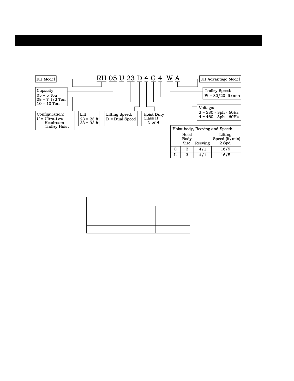
2.1.1 Product Code:
2.1.2 Hoist and Trolley Size – The RH Advantage trolley hoists are available in 2 basic sizes. These sizes
are referred to throughout this manual to identify what information applies to which trolley hoist. The
th
10
digit in the product code designates the sizes as shown in Table 2-1 below.
Table 2-1 Hoist and Trolley Sizes
10TH Digit in
Product Code
Hoist Size Trolley Size
G 2 2
L 3 3
2.1.3 Operating Conditions and Environment
Temperature Range: +14° to +104°F (-10° to +40°C)
Humidity: 80% or less
Electrical Enclosure Rating: IP55
Brake Enclosure Rating: IP23
Supply Voltage: 230V-3ph-60Hz or 460V-3ph-60Hz
Control Voltage: 110V-1ph-60Hz
-
8
Page 9

Table 2-2 RH Advantage Trolley Hoist – Hoist Specifications
Dual Speed
Output
(Hp)
Lifting Motor
3 Phase 60Hz
@460V @230V
Capacity
(Tons)
5
7 1/2
10
Product Code
RH05U23D4G-1-WA
RH05U33D4G-1-WA
RH08U23D3G-1-WA
RH08U33D3G-1-WA
RH10U23D4L-1-WA
RH10U33D4L-1-WA
2 = 230V – 3ph – 60Hz
1
4 = 460V – 3ph – 60Hz
Lifting Speed
Lift
(ft/min)
(ft)
Dual Speed
23 991
33 1101
23 991
33
23 2429
33
16/5 4/1
Reeving
(parts/
reeving)
Rope
(mm)
9 8.0/2.7 11.5/9.6 23.0/19.0
13 16.1/5.4 23.0/17.3 46.0/34.5
Rated Current
(amps)
Net
Weight
(lbs)
1101
2671
Table 2-3 RH Advantage Trolley Hoist – Trolley Specifications
Traversing Motor
Dual Speed 80/20 ft/min
Output
(Hp)
Rated Current
@460V @230V
(amps)
Capacity
(Tons)
5
7 1/2
10
Product Code
RH05U23D4G-1-WA
RH05U33D4G-1-WA
RH08U23D3G-1-WA
RH08U33D3G-1-WA
RH10U23D4L-1-WA
RH10U33D4L-1-WA
Standard
Flange Width
B
(in)
4.69 to 15.75 0.6/0.13 1.3/1.1 2.5/2.2
5.31 to 15.75 0.9/0.2 2.1/1.1 4.2/2.2
9
Page 10

2.2 Dimensions
Note: Ultra-Low headroom trolleys are suitable for use on S or W shaped beams.
Table 2-4 RH Advantage Trolley Hoist – Dimensions
Refer to Table 2-3 for flange range dimension B.
Refer to Table 2-5 for headroom dimension E.
S1
S2
(in)
S3
(in)
Capacity
(Tons)
5
7 1/2
10
Product Code
RH05U23D4G-1-WA
RH05U33D4G-1-WA
RH08U23D3G-1-WA
RH08U33D3G-1-WA
RH10U23D4L-1-WA
RH10U33D4L-1-WA
C
C1
C2
(in)
(in)
(in) D (in)
6.3 4.3 14.4 19.5 10.4 22.1 7.6 7.6
10.8 -2.8 16.9 24.6 13.2 24.5 10.7 10.2
D1
(in)
D2
(in)
E1
(in)
E2
(in)
I1
∅ R
(in)
23.6 5.3 11.2 7.1
39.4 8.3 23.2 7.9
23.6 5.3 11.2 7.1
39.4
29.1 6.3 13.4 9.4
49.6
(in)
(in)
4.92
8.3 23.2 7.9
7.87
9.4 29.5 10.6
Note: Ultra-Low headroom trolleys are suitable for use on S or W shaped beams.
Refer to page 9 for flange range B.
Table 2-5 RH Advantage Trolley Hoist – Headroom
Hoist
Code
G
Flange Range
(in)
4.69 to 6.49 18.9
6.50 to 15.75 10.9 + (1.23 x T)
L
5.31 to 10.51 24.0
10.52 to 15.75 11.4 + (1.20 x T)
*T in formulas is the exact beam flange width in inches.
Headroom, E*
(in)
Headroom, E
for 6 inch Flange
(in)
18.9
24.0
10
Page 11

Table 2-6 Bottom Hook – Dimensions
Capacity
(Tons)
5
7 1/2
10
Product Code
RH05U23D4G-1-WA
RH05U33D4G-1-WA
RH08U23D3G-1-WA
RH08U33D3G-1-WA
RH10U23D4L-1-WA
RH10U33D4L-1-WA
a
(in) b (in) c (in) d (in) e (in) f (in) g (in) h (in)
2.6 2.1 2.3 1.8 2.5 2.8 1.7 6.7
3.5 2.8 3.0 2.4 3.1 3.5 2.0 8.9
Table 2-7 Reaction Forces at Rated Load
Ultra- Low Headroom Trolley
Capacity
(Tons)
5
7 ½
10
RH05U23D4G-1-WA
RH05U33D4G-1-WA
RH08U23D3G-1-WA
RH08U33D3G-1-WA
RH10U23D4L-1-WA
RH10U33D4L-1-WA
Wheel Reaction Forces
Product Code
R1
R2
(lbs)
(lbs)
3819 1660
4356 1178
5569 2410
6356 1678
7523 3626
8704 2566
11
Page 12
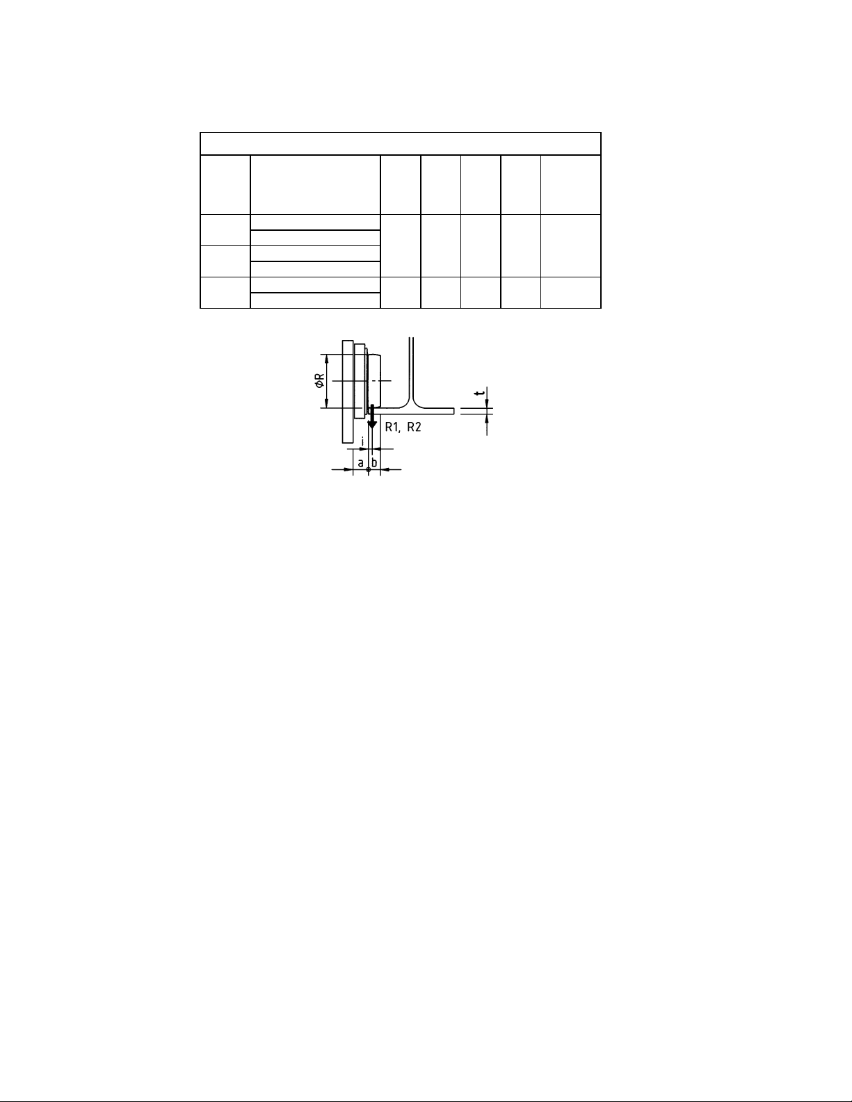
Table 2-8 Trolley Wheel – Dimensions
Maximum
Wheel
Capacity
(Tons)
5
7 ½
10
Product Code
RH05U23D4G-1-WA
RH05U33D4G-1-WA
RH08U23D3G-1-WA
RH08U33D3G-1-WA
RH10U23D4L-1-WA
RH10U33D4L-1-WA
a
(in) b (in) i (in)
1.38 1.14 0.47 4.92 0.91
1.77 1.50 0.75 7.87 1.50
Dia.
∅ R
(in)
Flange
Thickness
t
(in)
Note: See Ultra- Low Headroom Trolley Wheel Reaction Forces
Table 2-7 for reaction forces R1 and R2.
12
Page 13

3.0 Pre-operational Procedures
3.1 General Information
3.1.1 When the RH Advantage trolley hoist is incorporated into lifting systems utilizing other equipment,
follow and complete all pre-operational procedures and instructions provided with the equipment.
Special wiring considerations must also be taken to complete the integration of the RH Advantage
trolley hoist into the system.
3.1.2 The RH Advantage trolley hoist is generally delivered pre-assembled and shrink-wrapped on a pallet
or in a wooden crate (see Figure 3-1). During shipment and storage prior to installation, the trolley hoist
should be kept between –4° and +140°F (-20° and +60°C) and the relative humidity must not exceed
80%. The standard packaging is not watertight and rainproof.
3.1.3 The RH Advantage trolley hoist is shipped pre-lubricated and the gear box(s) are filled with the correct
amount and type of oil. Follow the lubrication requirements in Section 6.1 after the trolley hoist is
placed into service.
3.2 Handling
3.2.1 Transportation – Move the trolley hoist utilizing a fork lift, pallet jack or hoist/crane system. Do NOT
place the trolley hoist on its side (see Figure 3-2). Do NOT stack or place anything on top of the trolley
hoist or crate. Avoid swinging and unbalanced conditions (see Figure 3-3).
Figure 3-1 Shrink-Wrapped on Pallet Packaging and Crate Packaging
Figure 3-2 Do NOT Place Hoist on its Side.
13
Figure 3-3 Avoid Swinging and Unbalanced
Conditions.
Page 14

3.2.2 Lift points – The Advantage trolley hoists are equipped with lifting lugs to facilitate lifting the trolley
hoist with a hoist or crane (see Figure 3-4). During lifting do NOT support the trolley hoist any other
way.
Figure 3-4 Lift Points
3.3 Mounting Location
3.3.1
3.3.2 Ensure that there is adequate vertical and horizontal clearance along the entire range of the trolley
3.3.3
WARNING
structure are adequate to support the trolley hoist and its load. If necessary consult a professional that
is qualified to evaluate the adequacy of the suspension location and its supporting structure.
hoist’s motion (see Figure 3-5).
NOTICE
Prior to mounting the trolley hoist ensure that the trolley beam and its supporting
See Section 6.6 for outdoor installation considerations.
Figure 3-5 Trolley Hoist Clearances
14
Page 15

3.4 Assembly, Adjustments and Mounting
3.4.1 RH Advantage Trolley Hoist Installation
1) Make sure the mounting location complies with Section 3.3.
2) Install any additional devices, if any (power supply cords or pendants, for instance – see Section 3.5)
onto the trolley hoist. If the trolley hoist is not secured to a pallet, place and secure it to one making
sure that the trolley hoist is completely stable (see Figure 3-6).
3) Remove the Bottom Block from the pallet/packing and place it on the ground. Use a hoist or other
suitable lifting means to pickup the Bottom Block if it is heavier than 50 pounds (weight is written on the
container if it exceeds 50 pounds). Always lift/hold the Bottom Block from the Hook regardless if it is
lifted using a hoist or handled manually (see Figure 3-7).
4) On the counterweight side, loosen the Screws (D) that attach the Stiffening Plates (E) to Side Plates (F)
and loosen the Lock-Nuts (G) on the Stirrups (H) that secure the Side Plates (F) to the Load Bars (J)
(see Figure 3-10).
5) Remove the Nuts (K) and Socket Bolts (L) to remove the Spacers (M) from the Stirrups (H) so that the
Side Plates (F) on the counterweight side can move freely along the Load Bars (J) (see Figure 3-11).
6) For relatively small beam flange widths (at the lower end of the flange range – see Table 2-3), the
trolley Drive Shaft must be shortened to allow the Side Plates (F) to adjust close enough together as
required. Drive the Spring Pin attaching the Drive Pinion, slide the counterweight side Side Plates (F)
out and remove the Drive Shaft. After cutting the Drive Shaft, reinstall it onto the trolley and reattach
the Drive Pinion.
Figure 3-6 Trolley Secured to Pallet for Installation
Figure 3-8 Improper Method for Lifting
15
Figure 3-7 Lifting Bottom Block
Figure 3-9 Positioning the Trolley Hoist
Page 16

7)
8) Using a forklift or another suitable means, position the pallet so that the horizontal axis of the beam is
9) Temporarily slide the Side Plates (F) on the counterweight side along the Load Bars (J) so that the
10)
11) Use a movable scaffolding or a lifting platform so that one person can reach the height of the beam and
12) Guiding the fork lift operator, slowly raise the pallet while keeping it level until the running surface of the
13) From the scaffolding or lifting platform, slide the previously moved Side Plates (F) along the Load Bars
WARNING
with the trolley assembled together and securely attached to a pallet. Raise the trolley hoist with a
forklift, lifting platform, or other similar means. NEVER use slings to raise and install the trolley hoist
onto the beam (see Figure 3-8).
parallel to the horizontal axis of the hoist (see Figure 3-9).
distance between the faces of the trolley wheel is wider than the beam flange (see Figure 3-12).
WARNING
placement on the beam, ALWAYS move the Side Plates (F) on the counterweight side, DO NOT
remove the Side Plates (F) on the hoist side. DO NOT remove the counterweight.
guide the forklift operator. Raise the pallet slowly and carefully avoiding any swinging or oscillations
until the trolley hoist reaches the bottom flange beam.
trolley wheels are above the bottom flange of the beam. Then move the pallet horizontally until the
trolley wheels on the hoist side are over the bottom flange.
(J) until the trolley wheels are over the beam flange and the trolley wheel flanges of the Side Plates (F)
on the counterweight side are very close to the edge of the beam flange (see Figure 3-13).
When installing the trolley hoist on a beam, ALWAYS raise the hoist into position
This applies to ultra-low headroom trolleys only. When preparing the trolley for
Figure 3-10 Loosen Bolts
Figure 3-12 Slide Side Plates Out
16
Figure 3-11 Disconnect Tie Bar
Figure 3-13 Place Wheels on Beam
Page 17

14) Lower the pallet just enough until the trolley wheels are resting on the beam flange.
15) Check that all 4 trolley wheels rest correctly on the beam and that the clearance between the wheel
edge and the edge of the beam is 5/64 inch (2 mm) maximum at all 4 wheels (see Figure 3-14).
16) Remove the straps/ropes securing the trolley hoist to the pallet and lower the pallet to the ground.
17) Reattach the Spacers (M) to the Stirrups (F).
18) Using a torque wrench, fully tighten the Screws (D) attaching the Stiffening Plates (E) and the Locking
Nuts (G) of Stirrups (H) to the specified torque values shown in the Table 3-1.
Table 3-1 Torque Values
Figure 3-14 Verify Proper Adjustment
Load Bar Lock-Nuts (G)
Torque Value (ft-lbs)
Trolley Size
Stiffener Screws (D)
2 3
62 150
18 49
17
Page 18

3.5 Electrical Connections
3.5.1
3.5.2
3.5.3
3.5.4 Installing Power Supply Cord
CAUTION
CAUTION
Advantage’s lifting or traversing motors. Use of such devices may cause the motor brake and other
electrical components to malfunction. For variable frequency drives contact Harrington for more
information.
DANGER
been de-energized (disconnected). Lock out and tag out in accordance with ANSI Z244.1 “Personnel
Protection -Lockout/Tagout of Energy Sources”.
1) Refer to Figure 3-15 and the wiring diagram provided with the Hoist.
2) Remove Control Cover (A).
3) Loosen the Cable Fitting (C) located on the left side of the electrical enclosure and insert the power
supply cord. Pull through enough cord to reach the Power Supply Terminal (D) then securely
tighten the Cable Fitting (C).
4) Connect the 3 phase power leads (L1, L2 and L3) and the ground lead of the Power Supply Cord
to the Power Supply Terminal. Make sure the terminals are securely tightened and each lead is
completely isolated.
5) Replace the Control Cover (A). Be careful to not damage the seal or sealing surfaces and make
sure to securely tighten all fasteners or latches.
Ensure that the voltage of the electric power supply is proper for the trolley hoist.
Do NOT apply electronic soft-start control or voltage varying controls to the RH
Before proceeding, ensure that the electrical supply for the hoist or trolley has
Figure 3-15 Installing Power Supply Cord
18
Page 19

3.5.5 Installing Pendant
1) Refer to Figure 3-16, the wiring diagram and the interconnection diagram provided with the Hoist.
2) Remove Control Cover (A).
3) Access to Terminal Strip: For hoists with the integral electrical enclosures (plastic cover), the Terminal
Strips are located on the back side of the Panel (F). Gain access by removing the Socket Bolts (E)
securing the Panel (F), loosening the Set Bolts (G) on the Support Bars (H), then slide and rotate the
Panel (F) forward.
4) Loosen the Cable Fitting (C) located on the left side of the electrical enclosure and insert the pendant
cord. Pull through enough cord to reach the terminals then securely tighten the Cable Fitting (C).
5) Attach a strain relief cable or chain between the pendant and hoist. The cord or chain should attach to
the Small plate or eyebolt located at the bottom of the electrical enclosure.
6) Connect the individual pendant leads to the correct terminals as shown on the interconnection diagram.
Make sure the terminals are securely tightened and each lead is completely isolated.
7) Reattach the Control Panel (F) and replace the Control Cover (A) or close the metal electrical
enclosure. Be careful to not damage the seal or sealing surfaces and make sure to securely tighten all
fasteners or latches.
Figure 3-16 Installing Pendant
3.5.6 Connection to Electrical Power Source - The 3 power leads of the Power Supply Cable (normally red,
white, and black wires) should be connected to an Electric Power Disconnect Switch or Circuit Breaker.
This connection should be made so that the hoist is phased properly. Refer to Section 3.7.4 for
instructions on how to check for correct power supply phase connection.
3.5.7 Fuse/Breaker Capacity - The trolley and hoist's power supply should be equipped with overcurrent
protection such as fuses, which should be selected for 110% to 120% of total listed full load amperage,
and should be dual element time-delay fuses. For the total full load amperage draw, add the amperage
draws shown on the motor nameplates of ALL lifting and traversing motors.
3.5.8
DANGER
Grounding - An improper or insufficient ground connection creates an electrical
shock hazard when touching any part of the hoist or trolley. In the Power Supply Cable the ground wire
will be either Green with Yellow stripe or solid Green. It should always be connected to a suitable
ground connection. Do not paint the trolley wheel running surfaces of the beam as this can affect
grounding.
19
Page 20

3.6 Reeving and Adjustments
3.6.1 Reeving the bottom hook
1) Working from a scaffold or lifting platform, remove the Retaining Ring (B) and Load Limiter Pin (D)
from the Terminal Head Crossbar (A). Let the Load Limiter (C) rotate downward and remove the
Terminal Head (F) from the Lever Support/Load Limiter Assembly (C) by pulling out the Terminal
Head Pin (E). (see Figure 3-17). Note
and 10T trolley hoists.
2) From the ground, press the down button on the pendant until there is sufficient rope unwound to
reeve the hoist. Take care not to activate the down limit switch.
3) Place the Bottom Block on the ground so that it is positioned perpendicular to the hoist, and insert
the rope end into the bottom block as shown in Figure 3-18 for 4/1 reeved hoists (4 rope-falls). To
make rope insertion easier, temporarily attach a wire to the end of the rope with adhesive tape and
use the wire to pull the rope through the Bottom Block. Securely tie a string or cord to the end of
the rope and pull the wire rope up to the hoist from the scaffolding/platform. Thread the rope
through the return pulley installed in the hoist, then back through the Bottom Block (see Figure 3-
18).
4) Insert the end of the rope into the Terminal Head (F) and making sure at least 4 inches of rope
extend beyond the Terminal Head (F). Install the Wedge (G) into the Terminal Head (F) and pull
the rope until the Wedge (G) and the rope are tightly seated in the Terminal Head (F) (Figure 3-19).
: the Load limiter is standard on the 7½T, optional on the 5T
5)
6) Attach the Rope Clamp (H) 2 inches from the Terminal Head (F) and fully tighten the nuts. Do
7) Reattach the Terminal Head (F) to the Load Limiter (C) with the Terminal Head Pin (E) and
WARNING
Head (F).
NOT clamp the free end of the rope to the load bearing rope fall (the rope between the Terminal
Head (F) and the Bottom Block) (Figure 3-20).
reattach the Load Limiter (C) to the Terminal Head Crossbar (A) using the Load Limiter Pin (D) and
Retaining ring (B) (Figure 3-21). Note
and 10T trolley hoists.
Make certain the wire rope is tight against the Wedge (G) in the Terminal
: the Load limiter is standard on the 7½T, optional on the 5T
Figure 3-17 Remove Terminal
Head
Figure 3-18 Reeve the Bottom Block
20
Page 21

Figure 3-19 Install Wire Rope
on Terminal Head
3.6.2 Adjusting the Limit Switches:
Figure 3-20 Install Rope
Clamp
Figure 3-21 Install Terminal
Head
1)
2)
3)
4)
5) The lower Limit Switch (C) MUST be adjusted so that the hook can be lowered fully for the application,
6) Lower Limit Switch (C) Setting:
WARNING
on the Section Bar (D). NEVER adjust the limit switches past the red marks (Figure 3-22).
WARNING
and/or Bottom Block with any part of the hoist, structure or girder(s) (Figure 3-23).
WARNING
the position dictated by dimension “E” in Table 2-5.
WARNING
turns of wire rope completely wound on the drum (Figure 3-26).
WITHOUT the Hook/Bottom Block resting on the floor causing a slack condition in the wire ropes
(Figure 3-24).
+ Press the down button on the pendant and carefully lower the Hook to the position of maximum
descent for the application.
+ Loosen the screws (A) so that the lower Limit Switch (C) can freely run along the Section Bar (D)
then position the Switch so that it engages the striker on the rope guide. Secure the Switch in
position by tightening the Screws (A) (Figure 3-25).
+ Carefully verify the correct activation of the lower Limit Switch (C) by lowering the Hook several
times and readjust the Lower Limit Switch (C) as necessary.
The maximum upper and lower Limit Switch (B, C) adjustments are marked in red
The upper Limit Switch (B) MUST be adjusted to prevent the collision of the load
NEVER adjust the upper Limit Switch (B) so that the Bottom Block can rise above
The adjustment of the lower Limit Switch (C) MUST always ensure a minimum of 3
7) Upper Limit Switch (B) Setting:
+ Carefully raise the Hook until it is at the uppermost position dictated by dimension “E” in Table 2-5.
+ If the upper Limit Switch activates before the Hook reaches the uppermost position, measure how
far the Hook still needs to travel, then multiply the distance by 4. Adjust (increase) the length of
rope that extends beyond the Terminal Head by the resulting amount (Refer to Section 3.6.1).
+ Loosen the screws (A) so that the upper Limit Switch (B) can freely run along the Section Bar (D)
then position the Switch so that it engages the striker on the rope guide. Secure the Switch in
position by tightening the Screws (A) (Figure 3-25).
+ Carefully verify the correct activation of the upper Limit Switch (B) by raising the Hook several times
and readjust the Upper Limit Switch (B) as necessary.
21
Page 22

8) Check, according to the foreseen configuration, that the height of approach of the hook going up is not
less than that stated in Table 2-5 (dimension “H”).
Figure 3-22
Figure 3-23
Figure 3-24
Figure 3-25
22
Figure 3-26
Page 23

3.7 Pre-operational Checks and Trial Operation
3.7.1 Refer to the trolley hoist’s nameplate and record the Product Code, and Serial Numbers in the
space provided on the cover of this manual.
3.7.2 Perform pre-operational checks for the trolley hoist:
Measure and record the “k” dimension of the bottom hook on the hoist. See Table 5-5 under
Ensure that trolley is properly installed on the beam, and stops for the trolley are correctly
Ensure that all nuts, bolts and split pins (cotter pins) are sufficiently fastened.
Pull down on the Pendant and ensure that the Cord Strain Relief Cable takes the force, not
3.7.3 Confirm proper operation:
Before operating read and become familiar with Section 4 – Operation.
Before operating ensure that the hoist (and trolley) meets the Inspection, Testing and
Before operating ensure that nothing will interfere with the full range of the hoist’s (and
WARNING
ropes and all other lifting attachments before use. Inspect all load suspension members for
damage prior to use and replace or repair all damaged parts.
WARNING
to Section 3.6.
Section 5.
positioned and securely installed on the beam.
the Pendant Cord.
CAUTION
than 10% of the rated value, electrical devices may not function normally.
Maintenance requirements of ANSI/ASME B30.16.
trolley’s) operation.
Confirm the adequacy of the rated capacity for all slings, chains, wire
Verify and correct all wire rope irregularities prior to operating the hoist. Refer
Check supply voltage before everyday use. If the voltage varies more
3.7.4 Proceed with trial operation to confirm proper operation.
Verify that the controls agree with hoist direction. Make sure that depression of the Up button
lifts the Bottom Block and depression of the Down button lowers the Bottom Block. If the
Bottom Block does not move in the correct direction when the push buttons are pushed, the
power supply is phased incorrectly. In this case, turn off the power source or breaker switch
then reverse any two of the three wires at the power source. The hook will then move in
accordance with the directions of the push button.
Operate the trolley through its full range of motion. Make sure the trolley runs smoothly and
does not bind. Check the power supply and festoon system for proper operation
Perform inspections per Section 5.3, “Frequent Inspections”.
23
Page 24

4.0 Operation
4.1 Introduction
DANGER
DO NOT
WALK UNDER A SUSPENDED LOAD
WARNING
HOIST OPERATORS SHALL BE REQUIRED TO READ THE OPERATION SECTION OF THIS MANUAL; THE
WARNINGS CONTAINED IN THIS MANUAL, INSTRUCTION AND WARNING LABELS ON THE HOIST OR
LIFTING SYSTEM, AND THE OPERATION SECTIONS OF ANSI/ASME B30.16 and ANSI/ASME B30.10. THE
OPERATOR SHALL ALSO BE REQUIRED TO BE FAMILIAR WITH THE HOIST AND HOIST CONTROLS
BEFORE BEING AUTHORIZED TO OPERATE THE HOIST OR LIFTING SYSTEM.
HOIST OPERATORS SHOULD BE TRAINED IN PROPER RIGGING PROCEDURES FOR THE ATTACHMENT
OF LOADS TO THE HOIST HOOK.
HOIST OPERATORS SHOULD BE TRAINED TO BE AWARE OF POTENTIAL MALFUNCTIONS OF THE
EQUIPMENT THAT REQUIRE ADJUSTMENT OR REPAIR, AND TO BE INSTRUCTED TO STOP OPERATION IF
SUCH MALFUNCTIONS OCCUR, AND TO IMMEDIATELY ADVISE THEIR SUPERVISOR SO CORRECTIVE
ACTION CAN BE TAKEN.
HOIST OPERATORS SHOULD HAVE NORMAL DEPTH PERCEPTION, FIELD OF VISION, REACTION TIME,
MANUAL DEXTERITY, AND COORDINATION.
HOIST OPERATORS SHOULD NOT
CONTROL, PHYSICAL DEFECTS, OR EMOTIONAL INSTABILITY THAT COULD RESULT IN ACTIONS OF THE
OPERATOR BEING A HAZARD TO THE OPERATOR OR TO OTHERS.
HOIST OPERATORS SHOULD NOT
INFLUENCE OF ALCOHOL, DRUGS, OR MEDICATION.
OVERHEAD HOISTS ARE INTENDED ONLY FOR VERTICAL LIFTING SERVICE OF FREELY SUSPENDED
UNGUIDED LOADS. DO NOT
ARE NOT FREELY SUSPENDED, OR LOADS THAT ARE GUIDED.
HAVE A HISTORY OF OR BE PRONE TO SEIZURES, LOSS OF PHYSICAL
OPERATE A HOIST OR LIFTING SYSTEM WHEN UNDER THE
USE HOIST FOR LOADS THAT ARE NOT LIFTED VERTICALLY, LOADS THAT
NOTICE
• Read ANSI/ASME B30.16 and ANSI/ASME B30.10.
• Read the hoist manufacturer’s Operating and Maintenance Instructions.
• Read all labels attached to equipment.
24
Page 25

The operation of an overhead hoist involves more than activating the hoist’s controls. Per the ANSI/ASME B30
standards, the use of an overhead hoist is subject to certain hazards that cannot be mitigated by engineered features,
but only by the exercise of intelligence, care, common sense, and experience in anticipating the effects and results of
activating the hoist’s controls. Use this guidance in conjunction with other warnings, cautions, and notices in this manual
to govern the operation and use of your overhead hoist.
4.2 Shall’s and Shall Not’s for Operation
WARNING
Improper operation of a hoist can create a potentially hazardous
situation that, if not avoided, could result in death
and substantial property damage. To avoid such a potentially
hazardous situation THE OPERATOR SHALL:
• NOT operate a damaged, malfunctioning or
unusually performing hoist.
• NOT
• Be familiar with operating controls, procedures, and
• NOT
• NOT
• NOT
• NOT
• NOT
• NOT
• NOT
operate a hoist until you have thoroughly read
and understood Manufacturer’s Operating and
Maintenance Instructions or Manuals.
warnings.
operate a hoist that has been modified without
the manufacturer’s approval or without certification
that it is in conformity with ANSI/ASME B30
volumes.
lift more than rated load for the hoist.
use hoist with twisted, kinked, damaged, or
worn wire rope.
use the hoist to lift, support, or transport
people.
lift loads over people.
operate a hoist unless all persons are and
remain clear of the supported load.
operate unless load is centered under hoist.
or serious injury,
• NOT
• NOT
• NOT
• NOT
• NOT
• NOT
• NOT
• NOT
• NOT
• NOT
apply load unless the wire rope is properly
seated in its grooves.
apply load if bearing prevents equal loading
on all load-supporting ropes.
operate beyond the limits of the load wire
rope travel.
leave load supported by the hoist unattended
unless specific precautions have been taken.
allow the load wire rope or hook to be used as
an electrical or welding ground.
allow the load wire rope or hook to be touched
by a live welding electrode.
remove or obscure the warnings on the hoist.
operate a hoist on which the safety placards
or decals are missing or illegible
operate a hoist unless it has been securely
attached to a suitable support.
operate a hoist unless load slings or other
approved single attachments are properly sized,
and seated in the hook saddle.
• NOT
• Protect the hoist’s load wire rope from weld splatter
• NOT
• NOT
• NOT
attempt to lengthen the load wire rope or
repair damaged load wire rope.
or other damaging contaminants.
operate hoist when it is restricted from forming
a straight line from hook to support in the direction
of loading.
use load wire rope as a sling or wrap load
wire rope around load.
apply the load to the tip of the hook or to the
hook latch.
• NOT
• Take up slack carefully – make sure load is
• Shut down a hoist that malfunctions or performs
• Make sure hoist limit switches function properly.
• Warn personnel before lifting or moving a load.
• Warn personnel of an approaching load.
25
use the hoist in such a way that could result in
shock or impact loads being applied to the hoist.
balanced and load-holding action is secure before
continuing.
unusually and report such malfunction.
Page 26

CAUTION
Improper operation of a hoist can create a potentially hazardous
situation that, if not avoided, could result in minor
injury
, or property damage. To avoid such a potentially hazardous
situation THE OPERATOR SHALL:
• Maintain a firm footing or be otherwise secured
when operating the hoist.
• Check brake function by tensioning the hoist prior
to each lift operation.
• Use hook latches. Latches are to retain slings,
chains, etc. under slack conditions only.
• Make sure the hook latches are closed and not
supporting any parts of the load.
• Make sure the load is free to move and will clear all
obstructions.
• Avoid swinging the load or hook.
• Make sure hook travel is in the same direction as
shown on controls.
• Inspect the hoist regularly, replace damaged or
worn parts, and keep appropriate records of
maintenance.
or moderate
• Use the hoist manufacturer’s recommended parts
when repairing the unit.
• Lubricate load wire rope per hoist manufacturer’s
recommendations.
• NOT
• NOT
• NOT
• NOT
• NOT
use the hoist load limiting or warning device to
measure load.
use limit switches as routine operating stops.
They are emergency devices only.
allow your attention to be diverted from
operating the hoist.
allow the hoist to be subjected to sharp
contact with other hoists, structures, or objects
through misuse.
adjust or repair the hoist unless qualified to
perform such adjustments or repairs.
26
Page 27

4.3 Hoist and Trolley Controls
4.2.1 Dual Speed Pendant Control – Pendant controls
supplied with dual speed trolley hoists have two-step
control buttons. For low speed depress the button to
the first step and for high speed depress the button
fully to the second step. Use the Up button to raise
the hoist’s hook or the Down button to lower the hoist’s
hook as shown in Figure 4-1. Depress the Forward
and Reverse buttons to move the trolley horizontally.
To stop motion release the buttons.
Figure 4-1 Push Button
Pendant Control
27
Page 28

5.0 Inspection
5.1 General
5.1.1 The inspection procedure herein is based on ANSI/ASME B30.16. The following definitions are from
ANSI/ASME B30.16 and pertain to the inspection procedure below.
+ Designated Person – a person selected or assigned by the employer or employer’s representative
as being competent to perform the specific duties.
+ Qualified Person – a person who, by possession of a recognized degree in an applicable field, or
certificate of professional standing, or who, by extensive knowledge, training, and experience, has
successfully demonstrated the ability to solve or resolve problems relating to the subject matter and
work.
+ Normal Service – that distributed service, which involves operation with randomly, distributed loads
within the rated load limit, or uniform loads less than 65% of rated load for not more than 25% of
the time.
+ Heavy Service – that service, which involves operation within the rated, load limit that exceeds
normal service.
+ Severe Service – that service which involves normal or heavy service with abnormal operating
conditions.
5.2 Inspection Classification
5.2.1 The Initial Inspection – a designated person shall inspect prior to initial use all new, re-installed, altered,
or modified hoists/trolleys to ensure compliance with the applicable provisions of this manual.
5.2.2 Inspection Classification – the inspection procedure for hoists/trolleys in regular service is divided into
two general classifications based upon the intervals at which inspection should be performed. The
intervals in turn are dependent upon the nature of the critical components of the hoists/trolleys and the
degree of their exposure to wear, deterioration, or malfunction. The two general classifications are
herein designated as FREQUENT and PERIODIC, with respective intervals between inspections as
defined below.
5.2.3 FREQUENT Inspection – visual examinations by the operator or other designated personnel with
intervals per the following criteria:
Table 5-1 Frequent Inspection Intervals
Service Hoist and Trolley Interval
Normal Service Monthly
Heavy Service Weekly to Monthly
Severe Service Daily to Weekly
Special or
Infrequent
Service
Rope Inspection
Interval
Start of
Every Shift
As recommended by a
qualified person before
and after each occurrence.
28
Page 29

5.2.4 PERIODIC Inspection – visual inspection by a designated person with intervals per the following
criteria:
Table 5-2 Periodic Inspection Intervals
Service Hoist and Trolley Interval Rope Inspection Interval
Normal
Service
Heavy
Service
Severe
Service
Monthly
Weekly to Monthly
Daily to Weekly
As recommended by a
Special or
Infrequent
Service
qualified person before the
first such occurrence and
as directed by the
qualified person for any
subsequent occurrences.
5.3 Frequent Inspection
5.3.1 Inspections should be made on a FREQUENT basis in accordance with Table 5-3, “Frequent
Inspection.” Included in these FREQUENT Inspections are observations made during operation for
any defects or damage that might appear between Periodic Inspections. A designated person shall
evaluate and resolve the results of FREQUENT Inspections such that the hoist/trolley is maintained in
safe working condition.
1) At Least monthly (per OSHA), AND
2) Determined by a qualified person and based
on such factors as expected rope life as
determined by experience on the particular or
similar installations; severity of environment;
percentage of capacity lifts; frequency rates
of operation; and exposure to shock loads.
Inspections need not be at equal calendar
intervals and should be more frequent as the
rope approaches the end of its useful life.
(per ANSI B30.16-2.4.1)
Table 5-3 Frequent Inspection
All functional operating mechanisms for maladjustment and unusual sounds.
Hoist and trolley in accordance with ANSI/ASME B30.16
Operation of all limit switches and associated components
Upper limit devices in accordance with ANSI/ASME B30.16
Hoist/trolley braking system for proper operation
Hooks and hook latches in accordance with ANSI/ASME B30.10
Hook latch operation
Wire rope in accordance with Section 5.7
Wire rope reeving for compliance with Section 3.6 and 6.4
Proper function of pendant controls.
29
Page 30

5.4 Periodic Inspection
5.4.1 Inspections should be made on a PERIODIC basis in accordance with Table 5-4, “Periodic Inspection.”
A designated person shall make evaluation and resolution of the results of PERIODIC Inspections such
that the hoist is maintained in safe working condition.
5.4.2 For inspections where load suspension parts of the hoist/trolley are disassembled, a load test per
ANSI/ASME B30.16 must be performed on the hoist/trolley after it is re-assembled and prior to its
return to service.
Requirements of frequent inspection.
Evidence of loose bolts, nuts, or rivets.
Evidence of worn, corroded, cracked, or distorted parts such as suspension bolts,
mounting eye bolts, stirrup bolts, stiffening plate bolts, gears, pins, bearings, pins,
rollers.
Evidence of worn or damaged hook block, hook, clevises, yokes, shafts, wire rope
and wire rope attachments.
Evidence of damage to hook retaining nuts or collars and pins, and welds or rivets
used to secure the retaining members.
Table 5-4 Periodic Inspection
Evidence of worn or damaged rope-drum, rope guide and pulleys (sheaves).
End connections of wire rope.
Evidence of damage or excessive wear of load and idler sheaves.
Evidence of excessive wear on hoist or trolley brake system parts.
Evidence of excessive wear or damage to trolley wheels, gears and guide rollers.
Evidence of damage to supporting structure or trolley, if used.
Evidence of stress cracks on trolley stirrup plate welds.
Electrical apparatus for signs of pitting or any deterioration of visible controller
contacts and electrical components, such as, switches, contacts and pushbuttons.
Proper function of motion limit devices that interrupt power or cause a warning to be
activated.
Proper function of load limiter device.
Evidence of damage to all cables, including festooned cables.
Function labels on pendant control stations for legibility.
Function, instruction and warning labels properly attached to the hoist/trolley and
legible (see Section 1.2).
Verify proper lubrication of gears, rope drum, rope guide, rope, sheaves and all
other parts requiring lubrication.
5.5 Occasionally Used Hoists and Trolleys
5.5.1 Hoists that are used infrequently shall be inspected as follows prior to placing in service:
+ Hoist Idle More Than 1 Month, Less Than 1 Year: Inspect per FREQUENT Inspection criteria in
Section 5.3.
+ Hoist Idle More Than 1 Year: Inspect per PERIODIC Inspection criteria in Section 5.4.
30
Page 31

5.6 Inspection Records
5.6.1 Dated inspection reports and records should be maintained at time intervals corresponding to those
that apply for the hoist’s PERIODIC interval per Section 5.2.4. These records should be stored where
they are available to personnel involved with the inspection, maintenance, or operation of the
hoist/trolley.
5.6.2 A long-range rope inspection program should be established and should include records of
examination of ropes removed from service so a relationship can be established between visual
observation and actual condition of the rope.
5.7 Inspection Methods and Criteria
5.7.1 This section covers the inspection of specific items. The list of items in this section is based on those
listed in ANSI/ASME B30.16 for the Frequent and Periodic Inspection. In accordance with ANSI/ASME
B30.16, these inspections are not intended to involve disassembly of the hoist. Rather, disassembly for
further inspection would be required if frequent or periodic inspection results so indicate. Only a
qualified person trained in the disassembly and re-assembly of the hoist or trolley should perform such
disassembly and further inspection.
Table 5-5 Hoist (and Trolley) Inspection Methods and Criteria
Item Method Criteria Action
Functional
operating
mechanisms.
Limit Switch Function Proper operation. Actuation of limit switch should
Hoist Braking
System Operation
Hook – Surface
Condition
Hook – Fretting
wear
Hook – Stretch Measure The “g1” dimension should not be greater than
Hook – Bent
Shank or Neck
Hook Block
Assembly
Visual, Auditory Mechanisms should be properly adjusted and
should not produce unusual sounds when
operated.
stop hoist.
Function Braking distance with rated capacity should not
exceed the maximum braking distances listed in
Table 5-8.
Visual Should be free of significant rust; weld splatter,
deep nicks, or gouges.
Measure The “u” and “t” dimensions should not be less
than discard value listed in Table 5-6
1.1 times that measured and recorded at the time
of purchase (See Section 3.7). If recorded “g1”
values are not available for hooks when new, use
nominal “g1” values from Table 5-6.
Visual Shank and neck portions of hook should be free
of deformations.
Visual Should be free of significant rust; weld splatter,
nicks, gouges. Holes should not be elongated,
fasteners should not be loose, and there should
be no gap between mating parts.
Repair or replace
as required.
Repair or replace
as required.
Adjust or replace as
required (see
Section 6.2).
Replace.
Replace.
Replace.
Replace.
Tighten or replace
as required.
Hook Block –
Swivel Bearing
Visual, Function Bearing parts and surfaces should not show
significant wear, and should be free of dirt, grime
and deformations. Hook should rotate freely with
no roughness.
31
Clean/lubricate, or
replace as required.
Page 32

Table 5-5 Hoist (and Trolley) Inspection Methods and Criteria (continued)
Item Method Criteria Action
Hook Block –
Sheave(s) and
Shaft
Hook – Hook
Latches
Hoist – Housing
and Mechanical
Components
Trolley – Housing
and Mechanical
Components
Visual, Function Sheave(s) should be free of significant wear.
Sheave surfaces should be free of nicks, gouges,
dirt and grime. Bearing parts and surfaces of
Sheave and Shaft should not show significant
wear. Sheave should rotate freely with no
roughness or significant free play.
Visual, Function Latch should not be deformed. Attachment of
latch to hook should not be loose. Latch spring
should not be missing and should not be weak.
Latch movement should not be stiff – when
depressed and released latch should snap
smartly to its closed position.
Visual, Auditory,
Vibration,
Function
Hoist components including load blocks,
suspension housing, wire rope attachments,
clevises, yokes, suspension bolts, shafts, gears,
bearings, pins and rollers should be free of
cracks, distortion, significant wear and corrosion.
Evidence of same can be detected visually or via
detection of unusual sounds or vibration during
operation.
Visual, Auditory,
Vibration,
Function
Trolley components including load bars, trolley
wheels, trolley wheel axles, eye bolts, hex shafts,
gears, bearings, pins, rollers, and bumpers should
be free of cracks, distortion, significant wear, and
corrosion. Evidence of same can be detected
visually or via detection of unusual sounds or
vibration during operation.
Clean/lubricate, or
replace as required.
Replace.
Replace
Replace.
Bolts, Nuts and
Visual Bolts, nuts and rivets should not be loose. Tighten or replace
Rivets
Wire Rope Wedge Visual
The fixing (anchorage with wedge) must be
replaced if it shows deformation, wear, cuts, or
necking.
Wire Rope Drum Visual, Function Entire surface of the drum should be coated with
lubricant and should be free of dirt and grime.
Rope should fit in drum grooves.
Wire Rope Guide Visual, Function Rope Guide should be free of significant wear,
cracks, nicks, gouges, dirt and grime. Rope
Guide should take up rope play and move with
the rope on the drum during rope unwinding and
winding.
Wire Rope –
Reeving
Visual The wire rope should be reeved properly through
Hook Block Sheave (and Crossbar Sheave for
4/1hoist) – refer to Section 3.6. Wire rope should
be installed properly – refer to Section 6.4.
as required.
Replace
Clean/lubricate
(see Section 6.1).
Replace
Reeve/Install
properly.
32
Page 33

Table 5-5 Hoist (and Trolley) Inspection Methods and Criteria (continued)
Item Method Criteria Action
WARNING
wires, and condition. Special care should be taken when inspecting sections of rapid deteriation, such as the
following:
sections in contact with saddles, equalizer sheaves, or other sheaves where the rope travel is limited;
sections of the rope at or near terminal ends where corroded or broken wires may protrude;
sections subject to reverse bends;
sections of rope that are normally hidden during visual inspection, such as parts passing over sheaves.
Any condition that could degrade the strength and performance of the wire rope must be reported to a
qualified person for evaluation and disposition.
Wire Rope
Diameter
Wire Rope –
Broken
Wires or
Strands
Wire Rope –
Condition
The full length of the Wire Rope must be inspected for rope diameter, Broken strands or
Measure, Visual
Visual The wire rope should be inspected for broken
Visual
Any reduction in the diameter of the wire rope
must not be reduced due to corrosion, wear or
core collapse more than the discard value in
Table 5-7. The outer wires should not be worn
more than 1/3 of their original diameter.
wires or strands, paying close attention to end
connection and sections that frequently pass over
sheaves. The rope must NOT have:
More than the Maximum number of broken
wires listed in Table 5-7.
More than 4 broken wires in 1 strand in one
lay (one full revolution of a strand around the
rope).
Any broken strands.
Any wire rope deformation with permanent
bends, flattening, unraveling, birdcaging, etc.
General corrosion.
Rope core exposure.
One or more loose or protruding strands or
wires from rope.
Severely corroded or broken wires at end
connections.
Severely corroded, cracked, bent, worn or
improperly applied end connections
Any evidence of heat damage of any kind.
(Wire rope exhibits any heat discoloration or
localized loss of lubrication).
Replace. Inspect
drum and all
sheaves.
Replace
Replace
Wire Rope -
Lubrication
Trolley Side Plates Visual Must be free of significant deformation Replace
Trolley Wheel –
Condition
Visual The wire rope must be maintained in a clean and
well lubricated condition.
Visual Trolley Wheel should be free of significant wear,
cracks, nicks and gouges.
33
Clean/lubricate
(see Section 6.1).
Replace.
Page 34

Table 5-5 Hoist (and Trolley) Inspection Methods and Criteria (continued)
Item Method Criteria Action
Trolley Wheel –
Tread
Trolley Wheel –
Gear
Load Bar Visual, Measure Load Bar should be free of significant wear,
Visual, Measure Diameter of the tread surface should not be less
than 5% of its original diameter as new.
Visual Teeth should not be cracked, damaged, or
excessively worn.
Replace.
Replace.
Replace.
cracks, nicks and gouges. Load Bar should not
be bent.
Trolley Motor
Brake
Visual Braking action should not be overly abrupt and
should not allow excessive drift.
Adjust, Repair or
Replace as
required.
Contactor
Contacts
Visual Contacts should be free of significant pitting or
deterioration.
Replace.
Sheaves Visual Sheave should be free of significant wear. Replace.
Pendant –
Switches
Function Depressing and releasing push buttons should
make and break contacts in switch contact block
Repair or replace
as necessary.
and result in corresponding electrical continuity or
open circuit. Push buttons should be interlocked
either mechanically or electrically to prevent
simultaneous energizing of circuits for opposing
motions (e.g. up and down, forward and reverse).
Pendant -
Housing
Visual Pendant housing should be free of cracks and
mating surfaces of parts should seal without gaps.
Replace
Pendant - Wiring Visual Wire connections to switches in pendant should
Tighten or repair
not be loose or damaged.
Pendant and
Power Cords
Visual, Electrical
Continuity
Surface of cord should be free from nicks,
gouges, and abrasions. Each conductor in cord
Replace
should have 100% electrical continuity even when
cord is flexed back-and-forth. Pendant Cord
Strain Relief Cable should absorb the entire load
associated with forces applied to the pendant.
Pendant - Labels Visual Labels denoting functions should be legible. Replace
Warning Labels Visual Warning Labels should be affixed to the hoist (see
Replace
Section 1.2) and they should be legible.
Hoist Capacity
Label
Visual The label that indicates the capacity of the hoist
should be legible and securely attached to the
Replace
hoist.
34
Page 35

Table 5-6 Bottom Hook Dimensions
g1 Measured When New:
_____________________
Hook Identifier
th
(10
Character of
the Hoist Product
Code)
G (4 Falls)
L (4 Falls)
Nominal
(g1)
Dimension*
inch (mm)
1.97 (50) 2.28 (58) 2.17 (55.1) 1.77 (45) 1.68 (42.8)
2.48 (63) 2.95 (75) 2.81 (71.3) 2.36 (60) 2.24 (57)
(u) Dimension
inch (mm)
(t) Dimension
inch (mm)
Standard Discard Standard Discard
*These values are nominal since the dimension is not controlled to a tolerance. The “g1”
dimension should be measured when the hook is new – this becomes a reference measurement.
Subsequent measurements are compared to this reference to make determinations about hook
deformation/stretch. See Section 5.7, “Hooks – Stretch”.
35
Page 36

Table 5-7 Wire Rope Wear Dimensions
Rope Diameter
Hoist
Size
2 9 8.4 0.33 9 3 2.1 6 10.6
3 13 12.1 0.48 13 7 3.1 14 15.4
Standard Discard
(mm) (mm) (in)
Table 5-8 Braking Distance (inches) With Nominal Load
No. of Falls Speed
HOIST SIZE* ⇒
Maximum Limit Before Adjustment 1.77 2.36 2.95 3.54
4 Fall
16 ft/min
Best Value Following Adjustment 0.59 0.79 0.98 1.18
*To determine the hoist size, refer to Section 2.1.2.
Rope
Diameter
(mm)
Maximum Allowable Number of Broken Wires
For 6xDia. Length For 30xDia. Length
No.
Broken
Wires
Length
(in)
1 2 3 4
No.
Broken
Wires
Length
(in)
36
Page 37

6.0 Maintenance and Handling
6.1 Lubrication
6.1.1 Wire Rope:
+ For proper performance the Wire Rope must be maintained in a clean and well lubricated
condition.
+ The rope should be lubricated every 3 months (more frequently for heavier usage or severe
conditions).
+ To lubricate the rope, first remove any dirt, grime, moisture or other accumulations of
contaminates. Then coat the Wire Rope with Agip 360 EP/F oil or equivalent. Ensure that the
lubricant is applied to the entire surface of the rope over its entire length.
6.1.2 Wire Rope Drum, Hook Block and Sheaves:
+ The drum and hook block should be lubricated every 3 months (more frequently for heavier usage
or severe conditions).
+ Lubricate the Drum, Hook Block and Sheaves with Agip Blasia 320 oil or Agip Blasia GR MU3
grease.
6.1.3 Trolley Wheels and Gears:
+ The Trolley Wheels and Gears should be lubricated every 3 months (more frequently for heavier
usage or severe conditions).
+ Lubricate the Trolley Wheels and Gears with Agip Blasia GR MU3 grease
6.1.4 Hoist and Trolley Gearboxes – The hoist and trolley gearboxes are lubricated for life and should not
need any lubricant replacement.
6.2 Hoist Motor Brake
6.2.1 To keep your hoist working in optimum condition and prevent possible down time, it is recommended to
check your motor brake and adjustment at regular intervals.
6.2.2 Motor brake adjustment is as follows:
1)
2) Adjustment and inspection of the motor brake requires removal of the motor brake cover from the
3) To remove the cover (A), remove the 4 Cover Screws (B), then remove the Cover (see Figure 6-1).
4) Remove the 3 screws (E) from the Blocking Ring (D) of the brake lock (see Figure 6-2).
5) To adjust the brake, rotate the Blocking Ring (D) counterclockwise to increase brake pressure,
DANGER
been de-energized (disconnected). Lock out and tag out in accordance with ANSI Z244.1
“Personnel Protection –Lockout/Tagout of Energy Sources”.
hoist.
clockwise for less pressure. One complete revolution is equal to 1mm of axial movement. Moving
the ring may require using a screwdriver in the notch of the Blocking Ring (D) (see Figure 6-3)
Before proceeding, ensure that the electrical supply for the hoist or trolley has
6.2.3 Motor Brake Re-assembly – After the brake is properly adjusted and inspected, reassemble the parts in
reverse order of removal.
6.2.4 Motor Brake Check
1) Ensure that the motor runs freely and quietly.
2) Ensure that the brake is not overheating.
37
Page 38

3) Check that the brake adjustment has been performed correctly. Complete the brake test, first with
no load and then with a nominal load (see Table 5-8).
4) Readjust the brake as necessary.
5) It is recommended that the brake be replaced after 3 adjustments.
Figure 6-1
Figure 6-2
Figure 6-3
38
Page 39

6.3 Trolley Motor Brake
6.3.1 The Trolley Brake adjustment can be accomplished 2 ways:
+ External Method – External adjustment in the case of moderate wear or when changing the brake
pre-sets.
+ Internal Method – Internal adjustment is required after the External method does not provide
enough braking. This usually occurs when brake wear exceeds 1mm.
6.3.2 To adjust the trolley motor brake for either the external or internal method, it is necessary to
perform the following steps:
1)
2) Remove the trolley Motor Cover (A) by unscrewing the 4 Screws (B) (see Figure 6-4).
6.3.3 External Method – The external method allows the braking force to be increased or decreased as
required without disassembling the brake.
1) Remove the Lock-Nut ®, Fan (D), external Thickness Washers (E), Snap Ring (F), Pressure
2) To INCREASE braking, add some or all of the external Thickness Washers (E) to the Thickness
3) To DECREASE braking, remove a quantity of the internal Thickness Washers (E) adjacent to the
4) Reinstall the Spring (H), Pressure Washer (G), Snap Ring (F), Thickness Washers (E), Fan (D)
5) Reinstall the trolley Motor Cover (A) using the 4 Screws (B).
6) Perform brake tests and repeat the above steps as necessary to obtain the required trolley braking.
DANGER
been de-energized (disconnected). Lock out and tag out in accordance with ANSI Z244.1
“Personnel Protection –Lockout/Tagout of Energy Sources”.
Washer (G) and Spring (H) (see Figure 6-5 and 6-6).
Washers (E) adjacent to the motor as necessary to obtain the required braking force (see Figure 6-
6).
motor and add them to the external Thickness Washers (E) during re-assembly (between the fan
(D) and the snap ring (F) as required to obtain the required decrease in braking force (see Figure
6-6).
and Lock-Nut ®.
Before proceeding, ensure that the electrical supply for the hoist or trolley has
Figure 6-4
39
Figure 6-5
Page 40

Figure 6-6
6.3.4 Internal Method – The internal method allows the braking to be increased as required.
1) Remove the Lock-Nut ®, Fan (D), Snap Ring (F), Pressure Washer (G), Spring (H) and all
Thickness Washers (E) (see Figure 6-5 and 6-6).
2) Unscrew and remove the Hexagonal Spacers (J) and Nuts then remove the Motor Cover (P).
Carefully, so as not to damage the rotor and/or the winding, slide the Rotor (N) with Brake Block
(K) out of the motor completely (see Figure 6-7).
3) Remove the Snap Ring (L), external Drum Spacers (M), Brake Block (K), without removing the
internal Drum Spacers (M) nearest the rotor. Transfer the necessary quantity of external Drum
Spacers (M) to the Rotor (N) side of the brake block (K) to provide more braking (see Figure 6-8).
4) Reinstall the brake block (K), Drum Spacers (M), Snap Ring (L) and reinsert the rotor in the motor.
Reinstall the Motor Cover (P), Hexagonal Spacers (J) and Nuts (see Figure 6-9).
5) Confirm acceptable trolley braking distance. Perform the steps of Section 6.3.3 External Trolley
Brake Adjustment for further adjustment if necessary.
6.3.5 If the adjustment has been performed several times and the required braking cannot be obtained, it is
necessary to replace the motor cover (P), ordering ONLY original spare parts.
Figure 6-7
Figure 6-8
40
Figure 6-9
Page 41

6.4 Wire Rope
6.4.1 Lubrication and Cleaning – Refer to Section 6-1.
6.4.2
6.4.3 Wire Rope Removal
1)
2)
3)
4) Lower the Hook Block to the lowest possible position without touching the floor or ground.
5) Remove the Anchorage Assembly (F) by removing Pin (D) from the Terminal Head Cross Bar (A) to
6) Rotate the lever downwards until the Anchorage Pin (E) can be removed allowing the Anchorage (F) to
7) Remove the Wire Rope Clamp (G) and loosen the Wire Rope until the Terminal Wedge (H) can be
8) Remove (unreeve) the Wire Rope from the Bottom Block and all Sheaves.
WARNING
Inc. and is the correct wire rope for the hoist. If the wire rope is being replaced due to damage or
wear out, destroy the old rope to prevent its reuse.
CAUTION
following procedures.
CAUTION
during rope replacement. The Wire Rope Guide Tool is available from Harrington Hoists, Inc. (see
Figure 6-10).
CAUTION
Hook Block Sheaves and replace if necessary.
free the lever of the Load Limiter (C) (see Figure 6-11).
be removed for disassembly.
removed from the Anchorage Assembly (F) (see Figure 6-12).
Be certain that the replacement wire rope is obtained from Harrington Hoists,
The hoist must be properly powered and operational in order to perform the
It is strongly advised to use the Wire Rope Guide Tool (part number, DMF0A0000)
When replacing Wire Rope, check for wear on mating parts, i.e. Drum, Sheaves,
Figure 6-10
Figure 6-11
Figure 6-12
41
Page 42
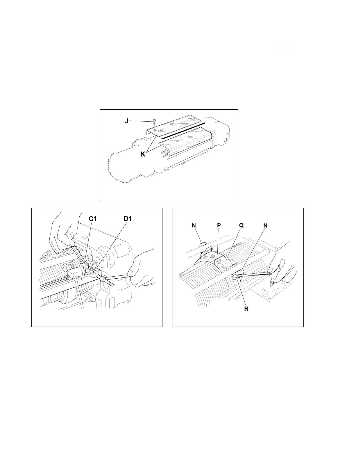
9) Remove the Dust Cover (K) by unscrewing the Dust Cover Screws (J) (see Figure 6-13). Note: Dust
cover is an option and may not be present.
10) Gain access to the Rope Guide and associated components. Remove the Limit Switch Assembly (C1)
removing the Screws (D1). Do not disconnect or change the setting of the Limit Switches (see Figure
6-14).
11) Remove the Screws ® and the Limit Switch Actuators (N) from the Rope Guide Ring Halves (P) and
(Q) (see Figure 6-15).
Figure 6-13
Figure 6-14
Figure 6-15
42
Page 43

12) Remove the Wire Clamping Spring (T) using the Wire Rope Guide Clamping Tool (S) and pliers to
remove the Clip (U) (see Figure 6-16).
13) Unscrew the Nuts (X) remove the Screws (V) and the Springs (W) from the Rope Guide Ring Halves
(P and Q), then remove the Ring Halve (Q) (see Figure 6-17).
14) Loosen the Screws (A1) of the Wire Rope Clamps (B1) and take out the Wire Rope and Ring Half (P)
(see Figure 6-18). For 4/1 Ultra-Low headroom versions it is necessary to rotate the Ring Half (P) over
the top of the drum to remove it from the hoist (see Figure 6-19).
Figure 6-16
Figure 6-17
Figure 6-18
Figure 6-19
43
Page 44

6.4.4 Wire Rope Installation
1)
2)
3)
4) Examine the Wire Rope Guide Ring Halves (P) and (Q) and the Drum after cleaning/degreasing
5) Verify proper fit of the Wire Rope Guide Ring Halves (P) and (Q) with the Drum, matching up the
6) Securing the Wire Rope to the Drum:
CAUTION
following procedures.
CAUTION
Hook Block Sheaves and replace if necessary.
WARNING
6-20).
thoroughly.
respective grooves and check that there is no excessive clearance. Check for pointed or sharp crests
and heavy wear and tear. Where necessary assess the need for replacing the wire rope guides and the
Drum.
Pass the end of the new Wire Rope up between the beam and the Drum, directly over the Drum, and
insert it through the “slit” of the Rope Guide Ring Half (P). Rotate the Rope Guide Ring Half (P) directly
over the Drum into position between the beam and Drum (see Figure 6-22). Secure the end of the
Wire Rope to the Drum with 3 Wire Rope Clamps (B1). Torque the Screws (A1) to the value shown in
Table 6-1 for your hoist (see Figure 6-21).
The hoist must be properly powered and operational in order to perform the
When replacing Wire Rope, check for wear on mating parts, i.e. Drum, Sheaves,
ALWAYS unwind the roll of the new Wire Rope without kinks or bends (see Figure
Figure 6-20
Table 6-1 Rope Clamp Torque Values
Hoist Size 2 3
Screw (A1) Dia (mm) M6 M8
Screw (A1) Torque 71 in-lbs 15 ft-lbs
44
Figure 6-21
Page 45
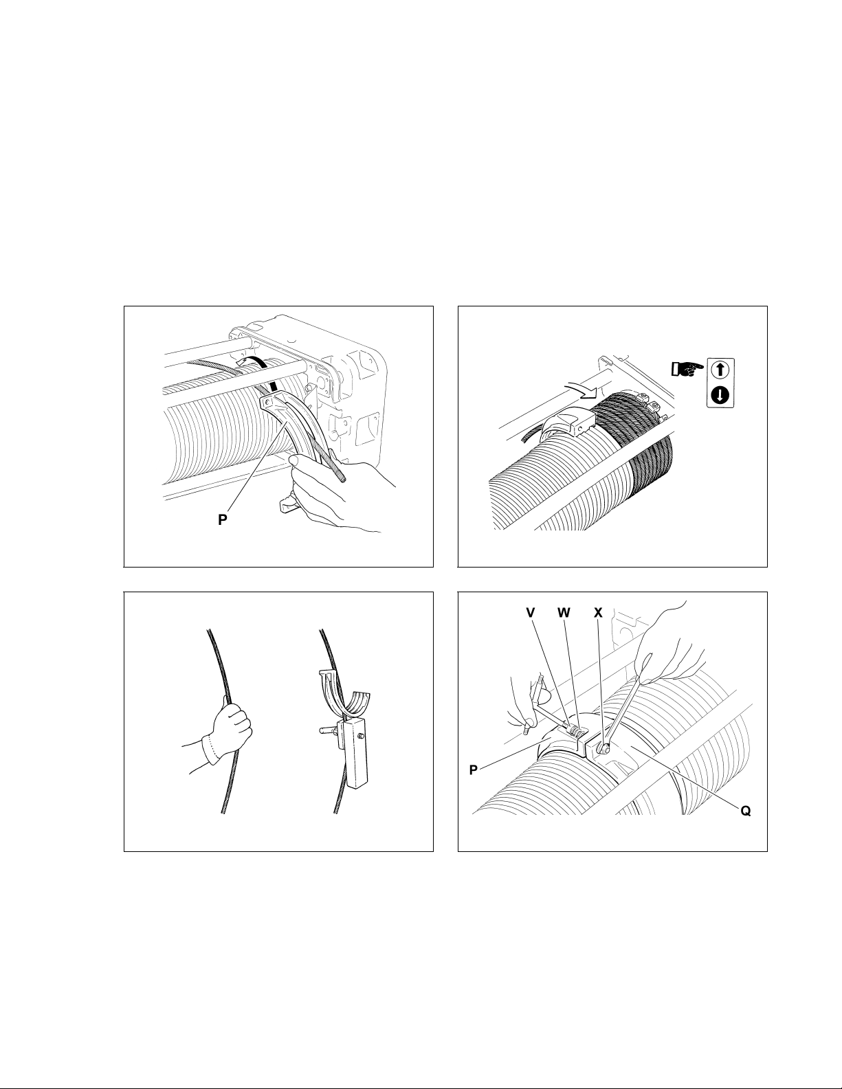
7) Press the “UP” button on the Pendant to wind the Wire Rope onto the Drum. Use protective gloves to
keep the Wire Rope constantly taut and well placed in the Drum grooves, letting the Wire Rope wind
around for at least 10 times (see Figure 6-23).
8) Without loosening the tension on the Wire Rope, clamp a weight onto the Wire Rope below the Rope
Guide, taking care not to damage the Wire Rope. Replacing the manual tension with the weight will
prevent the Wire Rope from unrolling off the Drum (see Figure 6-24).
9) Place both Rope Guide Ring Halves (P) and (Q) together on the Drum. Insert the Screws (V) and the
Springs (W) and tighten the Lock Nuts (X) until the Springs are partially collapsed, taking care not to
over-tighten the Springs, keeping the whole Rope Guide System elastic. Make sure at least 2 threads
protrude past the Lock Nuts (X) (see Figure 6-25).
Figure 6-22
Figure 6-23
Figure 6-24
Figure 6-25
45
Page 46

10) Insert the Wire Rope Clamp Runners (Z) piece by piece, into the slot on the side of the Rope Guide
Ring (P) (see Figure 6-26).
11) Reinstall the Limit Switch Actuators (N) onto the Rope Guide Ring Halves (P) and (Q) and tighten the
Screws (R) (see Figure 6-27).
12) Reposition the Wire Clamping Spring (T) on the Runners (Z). Use the Wire Rope Guide Clamping Tool
(S), to pull the Spring taut. Couple the ends of the Clip (U) onto the Spring using the pliers (see Figure
6-28).
13) Complete Reassembly:
Reinstall the Limit Switch Assembly (C1) and tighten the Screws (D1). Do not disconnect or change
the setting of the Limit Switches (see Figure 6-29). Reinstall the Dust Cover Halves (K) and tighten the
four (4) Screws (J) (see Figure 6-30). Note
: Dust cover is an option and may not be present.
Figure 6-26
Figure 6-27
Figure 6-28
Figure 6-29
14) Carry out again all the sequences described in Section 3.6 “Reeving and Adjustments”. Lubricate the
Wire Rope, the Rope Guide and Drum (see Section 6.1).
46
Page 47

6.5 Storage
6.5.1 The storage location should be clean and dry.
6.5.2 Care should be take to not damage any of the electrical power cords or fittings.
6.6 Outdoor Installations
6.6.1 For trolley and hoist installations that are outdoors, the trolley and hoist should be covered and
protected from the weather at all times.
6.6.2 Possibility of corrosion on components of the trolley increases for installations where salt air and high
humidity are present. The hoist and trolley may require more frequent lubrication. Make regular
inspections of the unit's condition and operation.
6.6.3 Optional weatherization package should be considered for high salt air and/or humid environments.
Optional Dust Covers
Figure 6-30
47
Page 48

7.0 Troubleshooting
WARNING
HAZARDOUS VOLTAGES ARE PRESENT IN THE HOIST AND IN CONNECTIONS BETWEEN
COMPONENTS.
Before performing ANY troubleshooting on the equipment, de-energize the supply of electricity to the equipment,
and lock and tag the supply device in the de-energized position. Refer to ANSI Z244.1, “Personnel Protection Lockout/Tagout of Energy Sources.”
Only Trained and competent personnel should inspect and repair this equipment.
Table 7-1 Troubleshooting Guide
Symptom Cause Remedy
Hoist and/or Trolley
moving in wrong
direction
Power supply reversed
phased
Improper electrical
connections
Loss of power
Wrong voltage or
frequency
Hoist overload Reduce load to within rated capacity of hoist.
Switch two (2) of the three (3) power supply cord wires at the
power source.
Refer to wiring diagram and check all connections.
Check circuit breakers, switches, fuses and connections on power
lines/cable.
Check voltage and frequency of power supply against the rating
on the nameplate of the motor.
Hoist and/or Trolley will
not operate
Motor overheated and
thermal overload
protector has tripped
Improper, loose, or
broken wire in hoist
electrical system
Brake does not
release
Defect in control
transformer
Faulty magnetic
contactor
Faulty Up or Down
Limit Switch
Motor burned out
See Trouble Shooting Problem "Motor or brake overheating".
Shut off power supply, check wiring connections on hoist control
panel and inside push-button pendant.
Check motor brake adjustment for proper clearance.
Check transformer coil for signs of overheating. Disconnect
transformer and check for open winding.
Check coil for open or short circuit. Check all connections in the
control circuit. Check for open contactors. Replace as needed.
Replace the Up and/or Down Limit Switch
Replace motor frame/stator, shaft/rotor, and any other damaged
parts.
48
Page 49

Table 7-1 Troubleshooting Guide
Symptom Cause Remedy
Hoist lifts but will not
lower
Hoist lowers but will
not lift
Down circuit open
Broken conductor in
pendant cord
Faulty magnetic
contactors
Faulty switch in
pendant
Check circuit for loose connections. Check down limit switch for
malfunction.
Check the continuity for each conductor in the cable. If one is
broken, replace entire cable.
Check coils for open or short circuit. Check all connections on
motor circuit. Check for burned contacts. Replace as needed.
Check electrical continuity. Check electrical connections.
Replace or repair as needed.
Hoist overloaded Reduce load to within rated capacity of hoist.
Low voltage in hoist's
power supply
Up circuit open
Faulty magnetic
contactors
Broken conductor in
pendant cord
Faulty switch in
pendant
Determine cause of low voltage and bring to within plus or minus
10% of the voltage specified on the motor nameplate. The
voltage should be measured at the hoist contactor.
Check circuit for loose connections. Check up limit switch for
malfunction.
Check coils for open or short circuit. Check all connections on
motor circuit. Check for burned contacts. Replace as needed.
Check the continuity of each conductor in the cable. If one is
broken, replace entire cable.
Check electrical continuity. Check electrical connections.
Replace or repair as needed.
Hoist will not lift rated
load or does not have
the proper lifting speed
Load drifts excessively
when hoist is stopped
Trolley drifts
excessively when
stopping
Hoist and/or Trolley
Motor or brake
overheating
Hoist overloaded Reduce load to within rated capacity.
Low voltage in hoist's
power supply
Determine cause of low voltage and bring to within plus or minus
10% of voltage specified on the motor nameplate. The voltage
should be measured at the hoist contactor.
Brake drags Check motor brake adjustment for proper clearance.
Motor brake not
holding
Motor brake not
holding
Clean and inspect brake lining. Check brake adjustment for
proper clearance.
Clean and inspect brake lining. Check brake adjustment. Replace
if necessary
Excessive load Reduce load to within rated capacity of hoist.
Excessive duty cycle Reduce frequency of lifts and/or trolley movement.
Wrong voltage or
frequency
Check voltage and frequency of power supply against the rating
on the nameplate on the motor.
Brake drags Check brake adjustment for proper clearance.
Above an ambient temperature of 104°F, the frequency of hoist
Extreme external
heating
operation must be reduced to avoid overheating of the motor.
Special provisions should be made to ventilate the hoist or
otherwise shield it from the heat.
49
Page 50

Symptom Cause Remedy
Hoist and/or Trolley
operates intermittently
Trolley making loud
noise.
Trolley will not move
Abnormal noise from
wire rope and/or drum
Table 7-1 Troubleshooting Guide
Contactor contacts
arcing
Loose connection in
circuit
Broken conductor in
Pendant Cord
Trolley wheel
maladjusted on beam
Trolley wheel spacing
on beam too tight
Lack of lubrication,
worn wire
rope/drum/sheaves
Check for burned contacts. Replace as needed.
Check all wires and terminals for bad connections. Replace as
needed.
Check for intermittent continuity in each conductor of the Pendant
Cord. Replace entire Pendant Cord if continuity is not constant.
Readjust the gap between the trolley wheel flange and the beam
flange.
Readjust the gap between the trolley wheel flange and the beam
flange.
Lubricate or replace wire rope/drum/sheaves
50
Page 51

8.0 Warranty
Warranty explanation and terms.
All products sold by Harrington Hoists, Inc. are warranted to be free from defects in material
and workmanship from date of shipment by Harrington for the following periods:
Manual Hoists & Trolleys - 2 years
Air and Electric Powered Hoists, Trolleys, and Crane Components - 1 year
Spare / Replacement Parts - 1 year
The product must be used in accordance with manufacturer’s recommendations and must
not have been subject to abuse, lack of maintenance, misuse, negligence, or unauthorized repairs
or alterations.
Should any defect in material or workmanship occur during the above time period in any
product, as determined by Harrington Hoist’s inspection of the product, Harrington Hoists, Inc.
agrees, at its discretion, either to replace (not including installation) or repair the part or product free
of charge and deliver said item F.O.B. Harrington Hoists, Inc. place of business to customer.
Customer must obtain a Return Goods Authorization as directed by Harrington or Harrington’s
published authorized repair center prior to shipping product for warranty evaluation. An explanation
of the complaint must accompany the product. Product must be returned freight prepaid. Upon
repair, the product will be covered for the remainder of the original warranty period. If it is
determined there is no defect, or that the defect resulted from causes not within the scope of
Harrington’s warranty, the customer will be responsible for the costs of returning the product.
Harrington Hoists, Inc. disclaims any and all other warranties of any kind expressed or
implied as to the product’s merchantability or fitness for a particular application. Harrington will
not be liable for death, injuries to persons or property or for incidental, contingent, special or
consequential damages, loss or expense arising in connection with the use or inability
whatever, regardless of whether damage, loss or expense results from any act or failure to act
by Harrington, whether negligent or wilful, or from any other reason.
51
Page 52

Notes
52
Page 53

9.0 Parts List
When ordering Parts, please provide the Hoist code number and serial number located on the Hoist nameplate
(see fig. below).
Reminder: Per sections 1.1 and 3.7.1 to aid in ordering Parts and Product Support, record the Hoist code number
and serial number in the space provided on the cover of this manual.
RH Advantage Series Nameplate
The parts list is arranged into the following sections:
Section Page
9.1 Hoist Parts . . . . . . . . . . . . . . . . . . . . . . . . . . . . . . . . . . . . . . . . . . . . . . . . . . . . . . . . . . . . . . . 54
9.2 Trolley Parts . . . . . . . . . . . . . . . . . . . . . . . . . . . . . . . . . . . . . . . . . . . . . . . . . . . . . . . . . . . . . 58
9.3 Electric Parts . . . . . . . . . . . . . . . . . . . . . . . . . . . . . . . . . . . . . . . . . . . . . . . . . . . . . . . . . . . . . 60
53
Page 54

10.1 Hoist Parts
Figure 10-1 Hoist Parts
54
Page 55

10.1 Hoist Parts
RH ADVANTAGE HOIST PARTS LIST
Fig.
No.
hoist motor – 2 speed, 230V 1 DRH2H0L23 DRH3H0L22
1
hoist motor – 2 speed, 460V 1 DRH2H0M23 DRH3H0M22
1A brake shoe + brake lining 1 DRH250373 DRH350375
1B fan cover 1 DRH150395 DRH350395
1C connection module 1 DRH1A0MC0 DRH3A0MC0
2 axial joint 1 DRH1A0GA0 DRH3A0GA0
2A half joint 1 DRH110230 DRH310230
2B rollers assembly 1 DRH110410 DRH310410
3 reducer 1 DRH2A0RL0 DRH3A0RL0
rope drum cover – 23 ft. lift 1 DRH2A0PN0 DRH3A0PN0
4
rope drum cover – 33 ft. lift 1 DRH2A0PL0 DRH3A0PL0
4A
4B
4C
4D rope clamp 4 DMF160060 DMF360060
4E
4F
4G "H" gasket 1 E2200H000*
4H suspension pivot 4 DRH260270 DRH360270
5A ring 1 DRH260140 DRH360140
5B rope press assembly 1 DRH210430 DRH310430
5C limit switch actuator 2 DRH260430 DRH360430
6A limit switches 2 E600FLR00
*Optional Equipment
rope drum – 23 ft. lift 1 DRH210130 DRH310130
rope drum – 33 ft. lift 1 DRH210150 DRH310150
spacer – 23 ft. lift 2 DRH260190 DRH360190
spacer – 33 ft. lift 2 DRH260210 DRH360210
staybolt – 23 ft. lift 1 DRH210090 DRH310090
staybolt – 33 ft. lift 1 DRH210110 DRH310110
limit switch cover – 23 ft. lift 1 DRH270240 DRH370240
limit switch cover – 33 ft. lift 1 DRH270260 DRH370260
dust cover angle – 23 ft. lift 2 DRH260220* DRH360220*
dust cover angle – 33 ft. lift 2 DRH260240* DRH360240*
5 rope guide 1 DRH2A0GH0 DRH3A0GH0
Part Name
Parts
Per
Hoist
RH10U23D4L2W-A
RH10U23D4L4W-A
RH10U33D4L2W-A
RH05U23D4G2W-A
RH05U23D4G4W-A
RH05U33D4G2W-A
RH05U33D4G4W-A
RH08U23D3G2W-A
RH08U23D3G4W-A
RH08U33D3G2W-A
RH08U33D3G4W-A
RH10U33D4L4W-A
55
Page 56
10.1 Hoist Parts
RH ADVANTAGE HOIST PARTS LIST
Fig.
No.
7
7A
Part Name
anchorage cross head assy, 23 ft. lift
anchorage cross head assy, 33 ft. lift
anchorage cross head, 23 ft. lift 1 DRH210062 DRH310061
anchorage cross head, 23 ft. lift 1 DRH210082 DRH310081
Parts
Per
Hoist
RH10U23D4L2W-A
RH10U23D4L4W-A
RH10U33D4L2W-A
RH05U23D4G2W-A
RH05U23D4G4W-A
RH05U33D4G2W-A
RH05U33D4G4W-A
RH08U23D3G2W-A
RH08U23D3G4W-A
RH08U33D3G2W-A
RH08U33D3G4W-A
RH10U33D4L4W-A
1 DRH2A0CN2 DRH3A0CN1
1 DRH2A0CL2 DRH3A0CL1
7B lever 1 DRH270195 DRH370195
7C limiter pivot 1 DRH270210 DRH370211
7D lever pivot 1 DRH270200 DRH370201
7E staybolt pivot 1 DRH170180
7F terminal pivot 1 DRH270300 DRH370300
7G terminal 1 DRH270150 DRH370150
7H terminal wedge 1 DRH270160 DRH370160
7I wire rope clamp 1 D65000F08 D65000F13
lever support DRH170220 DRH370220
8
load limiter
1
DRH1A0C20* DRH1A0C00 DRH3A0C20*
10A electrical frame 1 DRH210940 60854
10B cover 1 DRH210950 DRH360850
12
rope – 23 ft. lift 1 DRH270540 DRH270570 DRH370540
rope –
33 ft. lift 1 DRH270560 DRH270580 DRH370560
13 4 falls hook block 1 DRH2A0B40 DRH3A0B41
13A
hook side cheek 4 DMF150015 DRH350010
13B
hook pulley assembly 2 DRH210120 DRH310120
13C
side cheek gasket 6 DMF150005 DRH350005
13D
safety latch 1 DRH2A0MOS 3CR750MOS
*Optional Equipment
56
Page 57

10.1 Hoist Parts
This Page Intentionally Left Blank
57
Page 58

10.2 Trolley Parts
Figure 10-2 Trolley Parts
58
Page 59

10.2 Trolley Parts
RH ADVANTAGE TROLLEY PARTS LIST
Fig.
No.
Part Name
Parts
Per
Trly
RH10U23D4L2W-A
RH10U23D4L4W-A
RH10U33D4L2W-A
RH05U23D4G2W-A
RH05U23D4G4W-A
RH05U33D4G2W-A
RH05U33D4G4W-A
RH08U23D3G2W-A
RH08U23D3G4W-A
RH08U33D3G2W-A
RH08U33D3G4W-A
RH10U33D4L4W-A
14A drive plate 1 DST210065 DST310065
14B drive wheel assembly 2 DST210080 DST310080
14D buffer plate 4 DST250251 DST350251
14E buffer 4 DST150240 DST350240
14F drive sprocket 1 DST250105 DST350100
14G reducer 1 DST1A0R20 DST3A0R20
14H trolley motor – 2 speed, 230V 1 DGR1H03L0 DGR2H03L0
14H trolley motor – 2 speed, 460V 1 DGR1H03M0 DGR2H03M0
14H/1
motor cover 1 DGR120220 DGR220220
14H/2
fan 1 EVMEC0715 EVMEC0805
14H/3
fan cover 1 DGR160450 DGR260450
15 drive plate assembly 1 DST2B0E10 DST3B0E10
15A
drive plate 1 DST210065 DST310065
15B
cog wheel 1 DST250110 DST350110
16 idle plate assembly 2 DST2B0E20 DST3B0E20
16A idler plate 2 DST210075 DST310075
16B idle wheel assembly 2 DST210090 DST310090
17 connecting bar 2 DST250585 DST350585
18 transmission bar 1 DST150340 DST350340
19 roll pin 1 D08004030
20 connection plate, 23 ft. lift 2 DST250265 DST350265
20 connection plate, 33 ft. lift 2 DST250285 DST350285
21A balance weight, 23 ft. lift 1 DST210105 DST310105
21A balance weight, 33 ft. lift 1 DST210125 DST310125
21B transverse pivot pin 1 DST250520 DST350520
21C washer 2 DST250530 DST350530
21D balance weight spacer 2 DST250565 DST350565
21E hoist support 4 DST250620 DST350620
23 pulley assembly 1 DST2A0DR0 DST3A0DR0
23A
pulley transverse 1 DST250510 DST350510
23B
pulley pivot 1 DST250550 DST350550
23C
pulley 1 DRH210120 DRH310120
23D
pivot stop 1 DMF350260
59
Page 60

10.3 Electrical Parts
Figure 10-3 5T and 7½T Electrical Components
Figure 10-4 10T Electrical Components
60
Page 61

10.3 Electrical Parts
RH ADVANTAGE ELECTRICAL COMPONENTS PARTS LIST
Parts
POS. DESCRIPTION
Per
Hoist
RH10U23D4L2W-A
RH10U23D4L4W-A
RH10U33D4L2W-A
RH05U23D4G2W-A
RH05U23D4G4W-A
RH05U33D4G2W-A
RH05U33D4G4W-A
RH08U23D3G2W-A
RH08U23D3G4W-A
RH08U33D3G2W-A
RH08U33D3G4W-A
RH10U33D4L4W-A
1C10
1C12
lift/lower rev.contactor, 230V
lift/lower rev.contactor, 230V
1 E6C1D403F E6C1D633F
1
E6C1D403F
1C14 slow/fast contactor, 230V 1 E6C1D403F E6C1D633F
1C16 slow/fast contactor, 230V 1 E6C1D403F E6C1D633F
2C10 right/left contactor, 230V 1 EC2K0901F
2C12 right/left contactor, 230V 1 EC2K0901F
2C14 slow/fast contactor, 230V 1 EC1K0908F
0XFM05 transformer, 230V 1 E05160M30
0FU02 fus.sec.1TC 1 9006272
RH ADVANTAGE ELECTRICAL COMPONENTS PARTS LIST
Parts
POS. DESCRIPTION
Per
Hoist
E6C1D633F
RH10U23D4L2W-A
RH08U33D3G4W-A
1C10
1C12
lift/lower rev.contactor, 460V
lift/lower rev.contactor, 460V
RH05U23D4G2W-A
RH05U23D4G4W-A
RH05U33D4G2W-A
RH05U33D4G4W-A
RH08U23D3G2W-A
RH08U23D3G4W-A
RH08U33D3G2W-A
1 EC2D2501F E6C1D403F
1 EC2D2501F E6C1D403F
1C14 slow/fast contactor, 460V 1 E6C1D258F E6C1D403F
1C16 slow/fast contactor, 460V 1 E6C1D258F E6C1D403F
2C10 right/left contactor, 460V 1 EC2K0901F
2C12 right/left contactor, 460V 1 EC2K0901F
2C14 slow/fast contactor, 460V 1 EC1K0908F
0XFM05 transformer, 460V 1 E05063M10 E05160M10
0FU02 fus.sec.1TC 1 9006272
61
RH10U23D4L4W-A
RH10U33D4L2W-A
RH10U33D4L4W-A
Page 62

Notes
62
Page 63

Notes
63
Page 64

www.harringtonhoists.com
Harrington Hoists, Inc. Harrington Hoists – Western Division
401 West End Avenue 2341 Pomona Rincon Rd. #103
Manheim, PA 17545-1703 Corona, CA 92880-6973
Phone: 717-665-2000 Phone: 951-279-7100
Toll Free: 800-233-3010 Toll Free: 800-317-7111
Fax: 717-665-2861 Fax: 951-279-7500
RHAOM
 Loading...