

Page 1
This equipment should not be installed, operated or
all the contents of this manual. Failure to read and comply
with the contents of this manual can result in serious bodily
EFFECTIVE: March 11, 2013
ELECTRIC
CHAIN HOIST
NER2 / MR2 / TS2
FOOD GRADE MODEL
1/4 Ton through 2 Ton Capacit i es
Code, Lot and Serial Number
maintained by any person who has not read and understood
injury or death, and/or property damage.
Page 2
V Parts List
1.0 NER2 Parts List
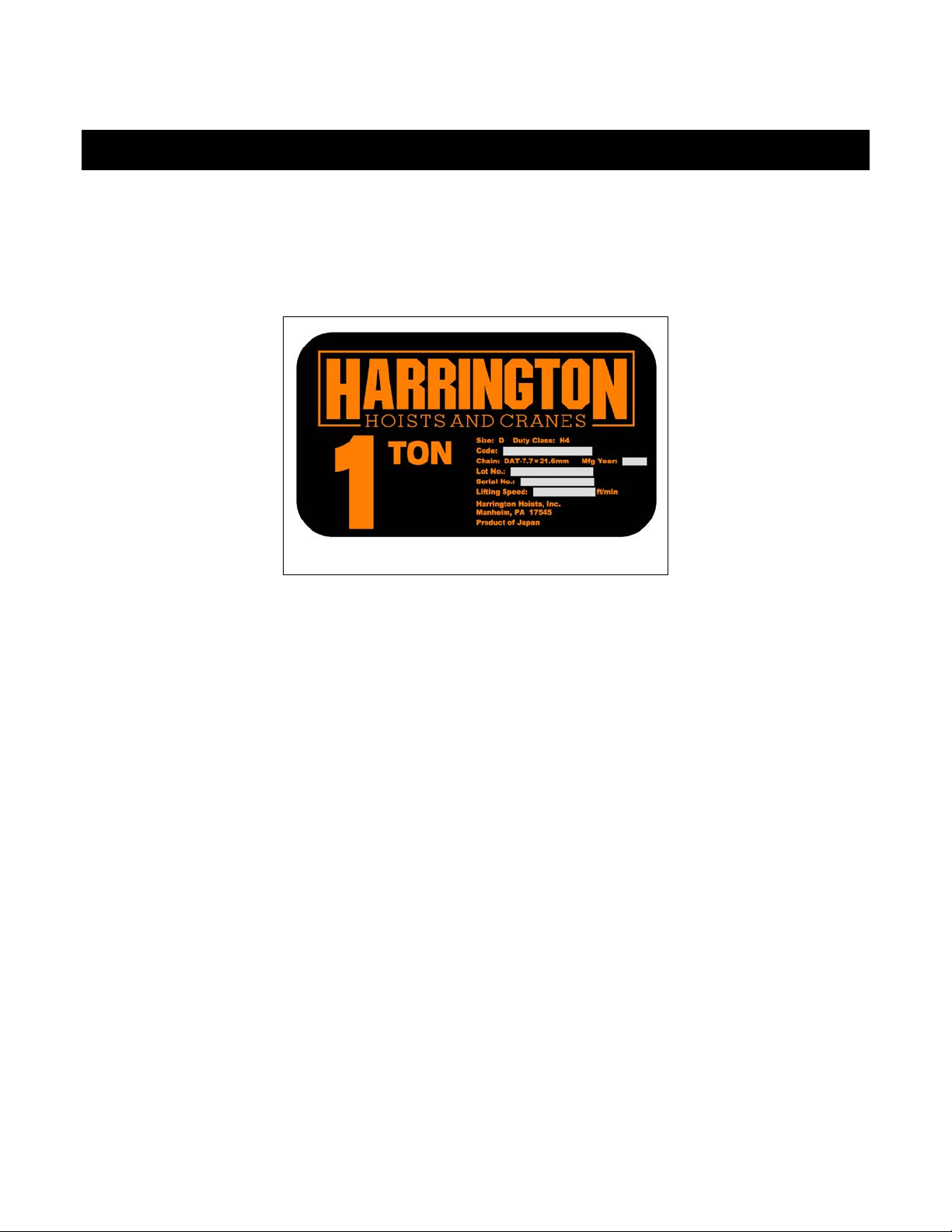
When ordering parts, please provide the hoist code number, lot number and serial number located on the hoist
nameplate (see fig. below).
Reminder: To aid in ordering parts and product support, record the hoist code number, lot number and serial
number in the space provided on the cover of this manual.
NER2 Series Nameplate
The parts list is arranged into the following sections:
Section Page
1.1 Housing and Motor Parts…………..…………….……………………………………………........ 22
1.2 Gearing Parts…………………………………………………………………………..................... 26
1.3 Hook and Chain Parts………………………………………………………………….…………... 30
1.4 Electric Parts (Single Speed)……………………………………………………………….……... 36
1.5 Electric Parts (Dual Speed)…………………………………………………………….………..... 38
1.6 Power Supply and Pendant Parts……………………………………...…………………………. 40
In the column "Parts Per Hoist" a designator is used for parts that apply only to a particular model or option.
Refer to Chapter 2, Section 2 for hoist model numbers and additional descriptions. The designators are:
S = Single Speed
D = Dual Speed
2V = 208/230 Volt Models
4V = 460 Volt Models
21
Page 3
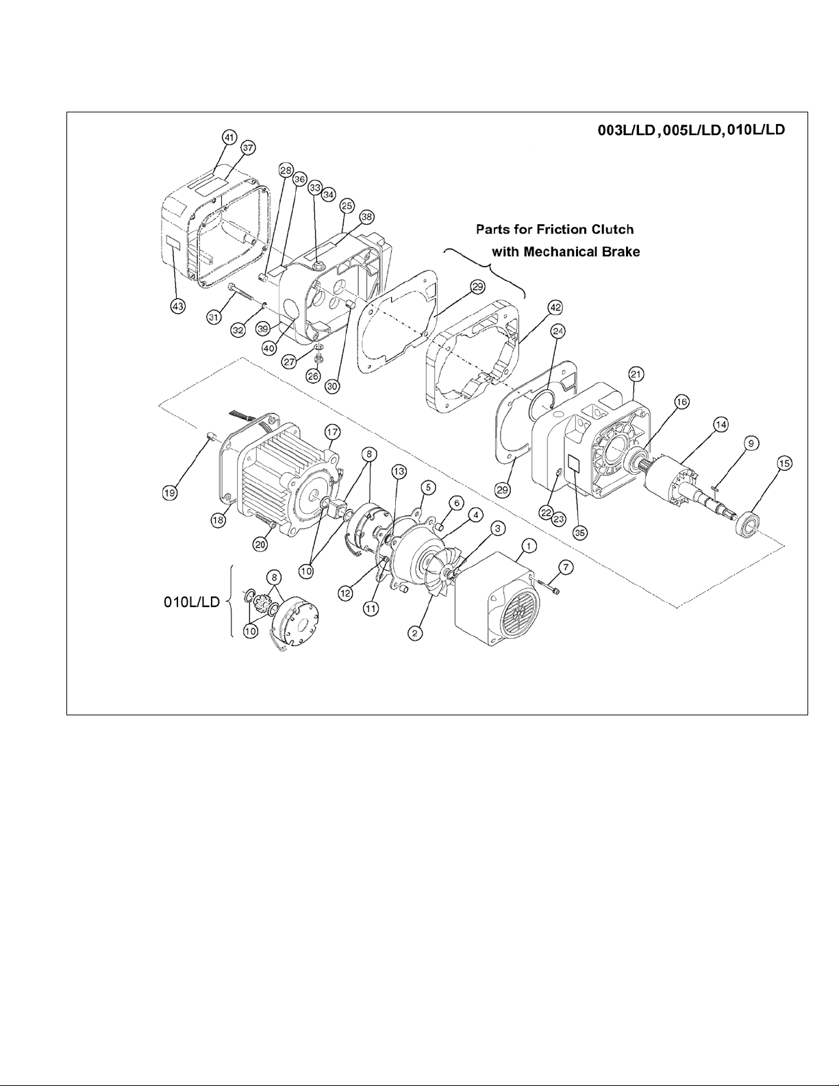
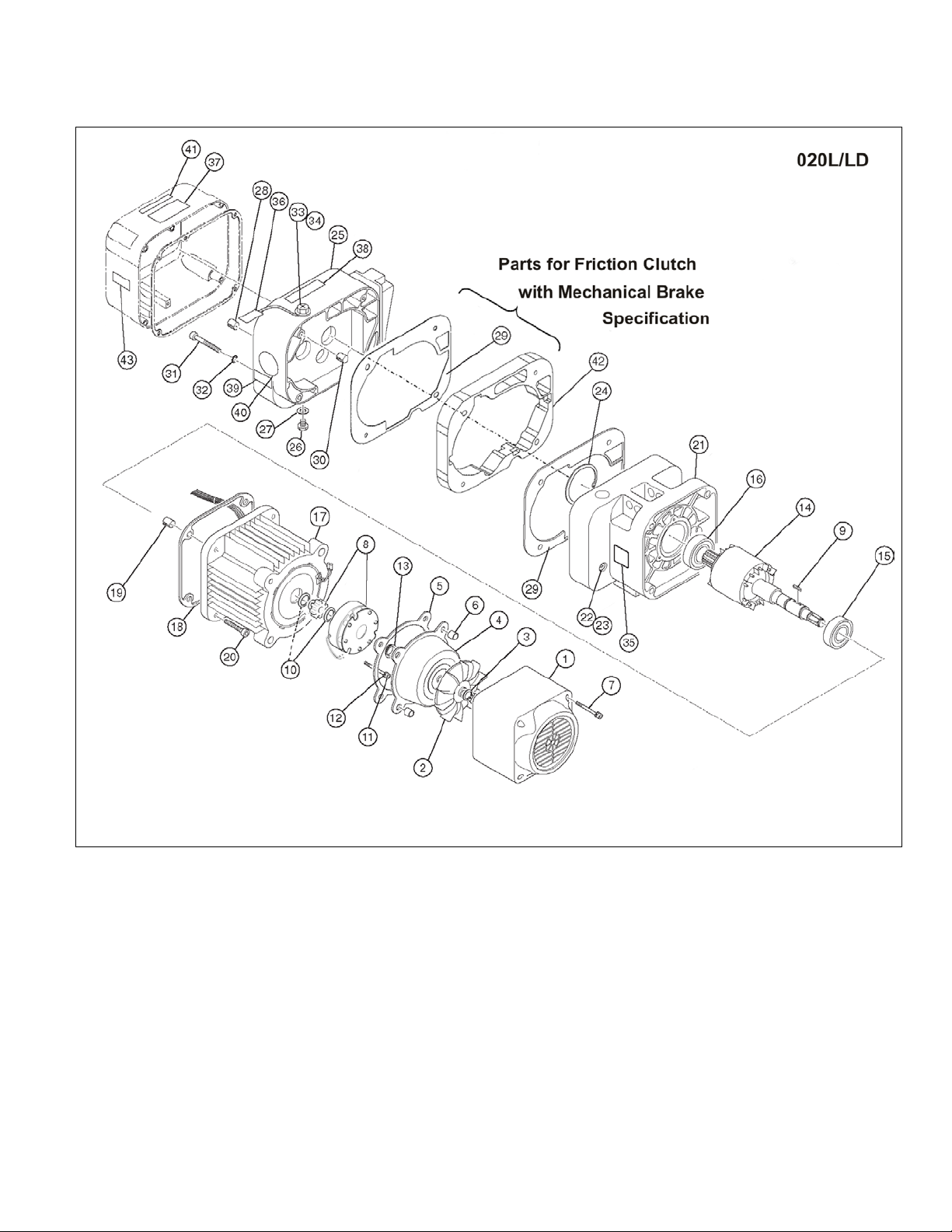
1.1 Housing and Motor Parts
Figure 1-1 Housing and Motor Parts
22
Page 4
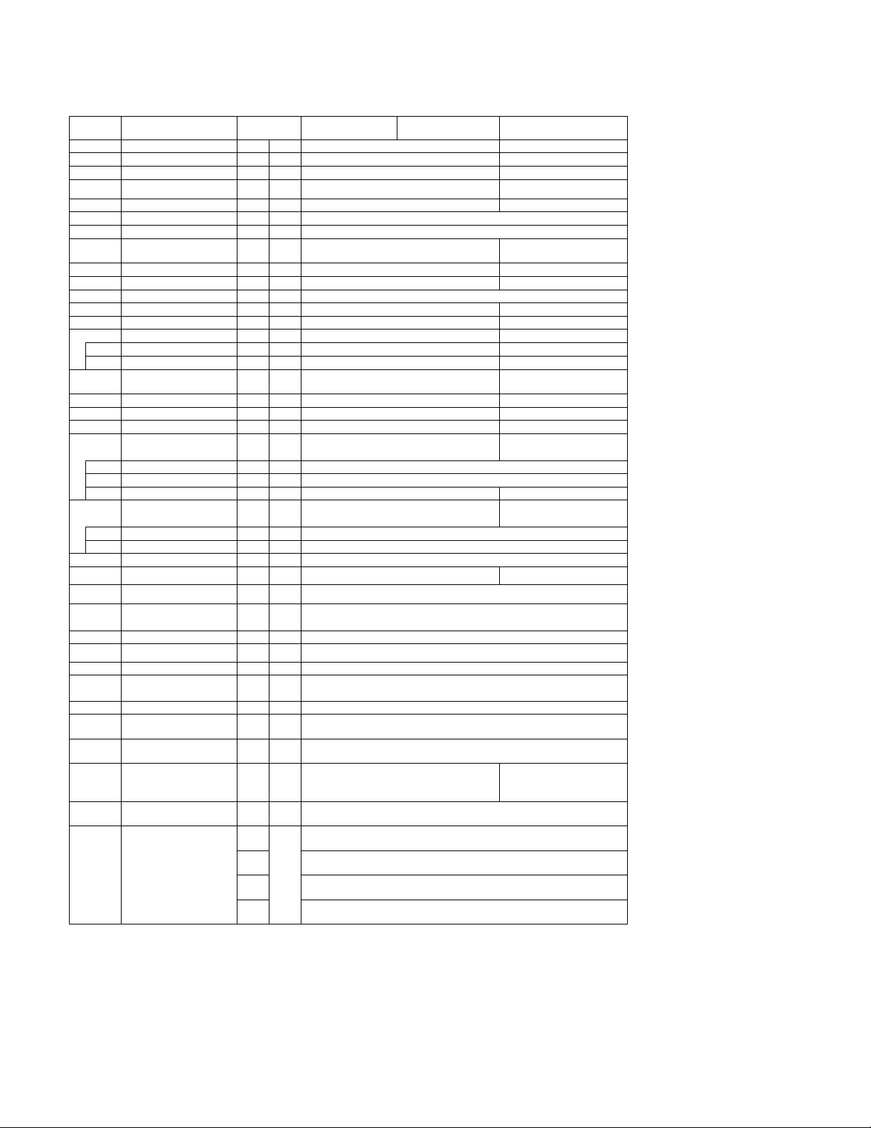
Figure
No.
Parts Per
Hoist
1
Fan Cover
1
2AFG005L9107
2AFG010L9107
2
Fan 1
ER2CL9108
ER2CS9108
3
Snap Ring
1
9047113
9047113
5
Packing B
1
ER2CL9119
ER2CS9119
6
Set Pin S
2
ES120003
7
Socket Bolt
4
J1BEE0504522
9
Key B 1
ER2CL9360
ER2CS9360
10
Snap Ring
2
9047116
9047124
11
Socket Bolt
3
9091254
12
Spring Lock Washer
3
J1WB07420080
J1WB07420100
13
V Ring 1
ER2CS9210
ER2CS9210
14
Motor Shaft With R otor
1
ER2CL5502
ER2DL5502
15
Ball Bearing
1
9000904
9000905
16
Ball Bearing
1
9000904
9000922
Stator
18
Packing M
1
ER2CS9118
ER2DS9118
19
Set Pin S
2
ES120010S
ER1DS9138
20
Socket Bolt
4
J1BEE0803535
J1BEE1003535
22
Oil Plug 1
E3S111003
23
Plug Packing
1
E3S112003
24
Snap Ring
1
9047262
9047268
26
Oil Plug 1
E3S111003
27
Plug Packing
1
E3S112003
28
Spring Pin
1
E3S129005S
32
Toothed Lock Washer
4
9679709
34
Eyebolt Packing
1
ES127005S
Name Plate
36
Oil Full Tag
1
ER1BS9953
Warning Sticker E
(Disconnect Power)
Name Plate OF (Correct
Warning Sticker HW
S,2
V
D,2
V
D,4
V
1.1 Housing and Motor Parts
Part Name
4 Brake Cover 1 ER2CL9115 ER2CS9115
Electromagnetic Brake
8
Assembly
Motor Frame With
17
21 Body B Assembly 1 3AFG005S6101 3AFG010S6101
1 MBABB0ENA MBABB09NA
1 3AFG005L5501 3AFG010L5501
003L/LD 005L/LD 010L/LD
25 Gear Case 1 3AFG005S6103 3AFG010S6103
29 Packing G 1 ER2CS9116 ER2DS9116
30 Set Pin S 2 ES120003
31 Socket Bolt 4 9091262
33 Oil Fill Plug 1 ER1BS9135
35
Load Side E
37
38
Oil Required)
Name Plate AD (Speed
40
Letter)
41
(Hot Surface)
43 Check Voltage Label
1 ER1BS9960
1 ER2CS9936
1 2AFG003S9845
1 ER1BL9868 ER1BL9868
D 1 ER2CI9806
V
S,4
1
ECP99NVVB
ECP99NVVA
ECP99NVWB
ECP99NVWA
23
Page 5
1.1 Housing and Motor Parts
Figure 1-2 Housing and Motor Parts
24
Page 6
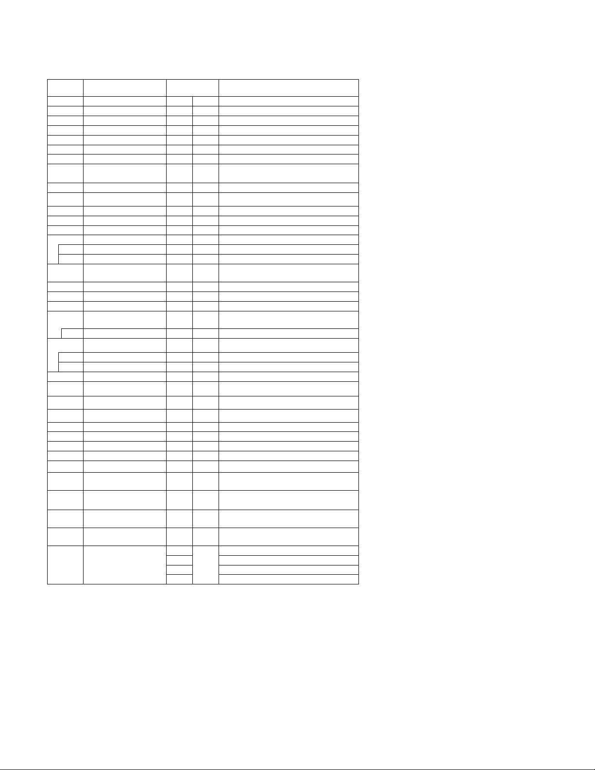
Figure
No.
Part Name
Parts Per
Hoist
1
Fan Cover
1
2AFG020L9107
2
Fan 1
ER2DS9108
3
Snap Ring
1
9047116
4
Brake Cover
1
ER2DS9115
5
Packing B
1
ER2DS9119
6
Set Pin S
2
ES120003
7
Socket Bolt
4
J1BEE0504522
Electromagnetic Brake
9
Key B 1
ER2DS9360
11
Socket Bolt
3
9091254
12
Spring Lock Washer
3
J1WB07420120
13
V Ring 1
ER2DS9210
14
Motor Shaft With Rotor
1
ER2EL5502
15
Ball Bearing
1
9000905
16
Ball Bearing
1
9000906
Motor Frame With
18
Packing M
1
ER2ES9118
19
Set Pin S
2
ER2ES9138
20
Socket Bolt
4
J1BEE1204040
24
Snap Ring
1
9047280
26
Oil Plug 1
E3S111003
27
Plug Packing
1
E3S112003
28
Spring Pin
1
E3S129005S
33
Oil Fill Plug
1
ER1BS9135
34
Eyebolt Packing
1
ES127005S
35
Name Plate Load Side E
1
ER1BS9960
Warning Sticker E
(Disconnect Power)
Name Plate AD (Speed
Letter)
Warning Sticker HW
D,4V
ECP99NVWA
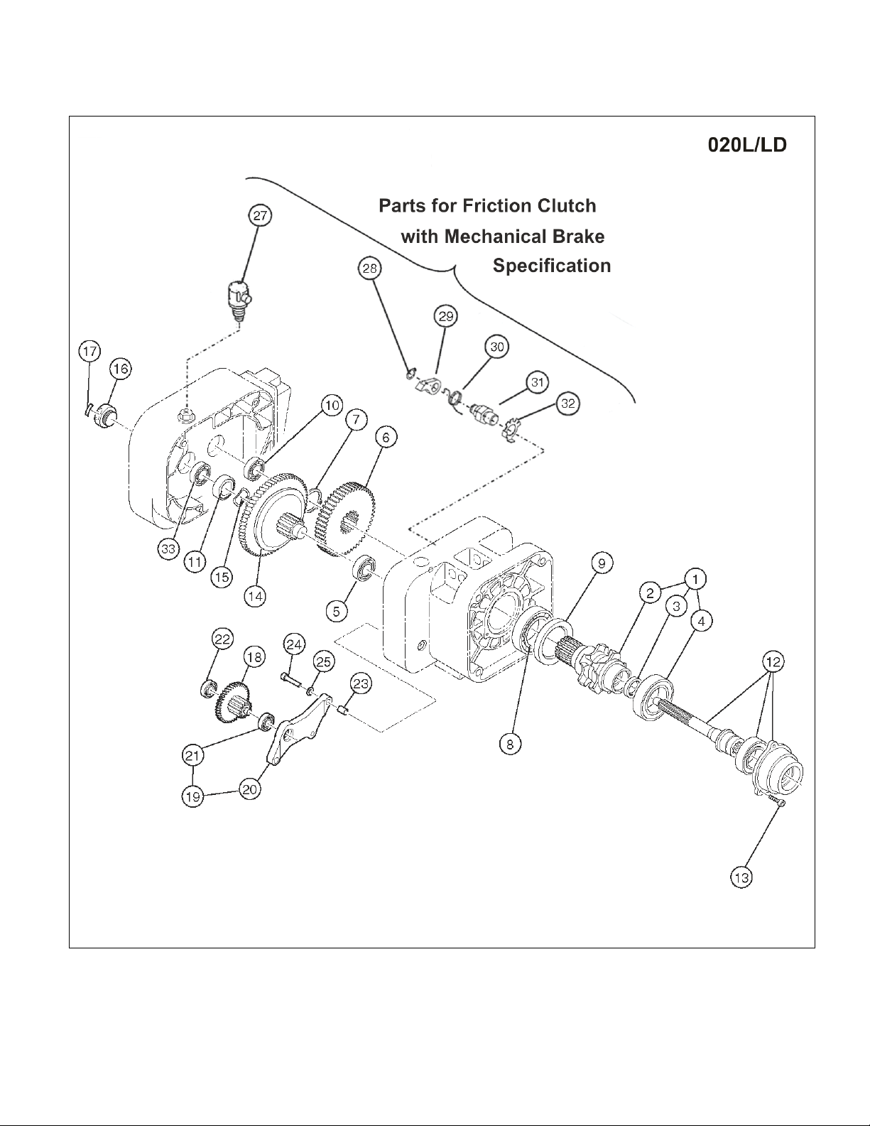
1.1 Housing and Motor Parts
020L/LD
8
Assembly
10 Snap Ring 2 9047124
17
Stator
21 Body B Assembly 1 3AFG020S6101
25 Gear Case 1 3AFG020L6103
29 Packing G 1 ER2ES9116
30 Set Pin S 2 ES120010S
31 Socket Bolt 4 9091286
32 Toothed Lock Washer 4 9679711
1 MBABB18NA
1 3AFG020L5501
36 Oil Full Tag 1 ER1BS9953
37
Name Plate OF (Correct
38
Oil Required)
40
41
(Hot Surface)
43 Ch eck Voltage Label
1 ER2CS9936
1 2AFG003S9845
1 ER1BL9868
D 1 ER2CI9806
S,2V
S,4V ECP99NVVA
D,2V ECP99NVWB
1
ECP99NVVB
25
Page 7
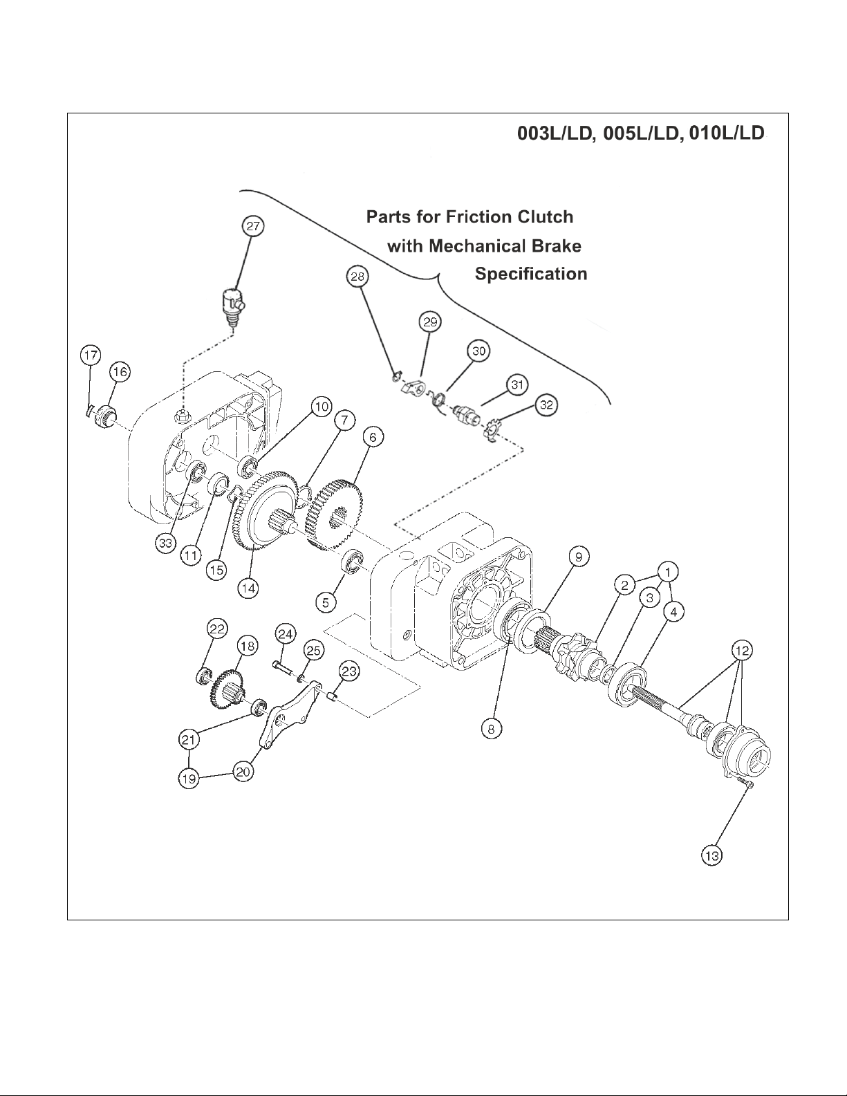
1.2 Gearing Parts
Figure 2-1 Gearing Parts
26
Page 8
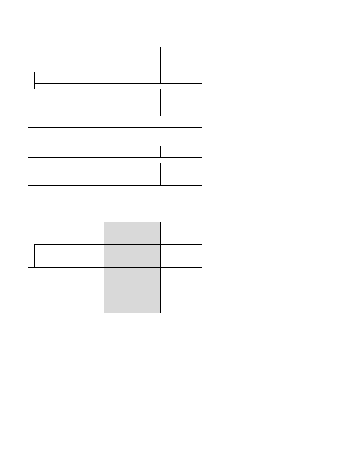
Figure
Parts
Hoist
Load Sheave
3
Oil Seal 1 ES221010S
ES221010S
4
Ball Bearing
1
9000508
7
Snap Ring
1
9047135
8
Ball Bearing
1
9000107
9
Oil Seal
1
ES232005S
11
Oil Seal
1
E6F235003S
Name Plate FP
Prohibited)
No.
Part Name
Per
003L/LD 005L/LD 010L/LD
1.2 Gearing Parts
1
Assembly
2 Load Sheave 1 ER2DS9241 ER2DS9241
5 Ball Bearing 1 9000302 9000304
6 Load Gear 1 ER2CL9240 ER2DS9240
10 Ball Bearing 1 9000201
12 Pinion Assembly 1 ER2CS5220 ER2DS5220
13 Socket Bolt 3 90912149
Friction Clutch
14
Complete
Assembly
15 Wave Washer 1 E1DBX20S9311
16 Nut Cover 1 ER1CS9235
(Adjustment Of
17
Friction Clutch
18 Gear B Assembly 1 ER2DL5262
Gear Holder
19
Plate Assembly
Gear Holder
20
Plate
21 Ball Bearing 1 9000101
1 ER2CS6241 ER2DS6241
1 ER2CL1223 ER2DL1223
1 ER1BS9892
1 ER2DL6261
1
ER2DL9261
22 Ball Bearing 1 9000100
23 Set Pin S 2 ES120003
24 Socket Bolt 3 9091252
Spring Lock
25
Washer
3 9012709
27
Page 9
1.2 Gearing Parts
Figure 2-2 Gearing Parts
28
Page 10
Assembly
2
Load Sheave
1
ER2ES9241
3
Oil Seal 1 ER2ES9221
4
Ball Bearing 1 9000609
7
Snap Ring 1 9047150
8
Ball Bearing 1 9000110
9
Oil Seal 1 ER2ES9244
10
Ball Bearing 1 9000303
11
Oil Seal 22 1 ER1DS9233
13
Socket Bolt 3 90912149
Friction Clutch
Assembly
15
Wave Washer
1
ER1DS9234
16
Nut Cover 1 ER1DS9235
Name Plate FP
Prohibited)
Figure
No.
1
5 Ball Bearing 1 9000405
6 Load Gear 1 ER2EL9240
12 Pinion Assembly 1 ER2EL5220
14
Part Name
Load Sheave
Complete
Parts
Per
Hoist
1 ER2ES6241
1 ER2EL1223
020L/LD
1.2 Gearing Parts
(Adjustment Of
17
Friction Clutch
18 Gear B Assembly 1 ER2EL5262
Gear Holder
19
Plate Assembly
Gear Holder
20
Plate
21 Ball Bearing 1 9000202
22 Ball Bearing 1 9000201
23 Set Pin S 2 ES120010S
24 Socket Bolt 3 9091275
Spring Lock
25
Washer
1 ER1BS9892
1 ER2EL6261
1 ER2EL9261
3 9012711
29
Page 11
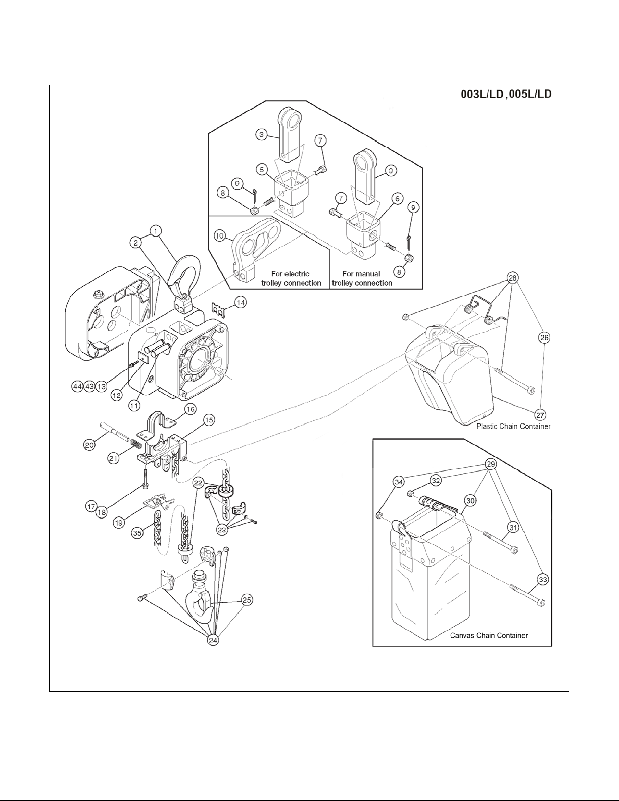
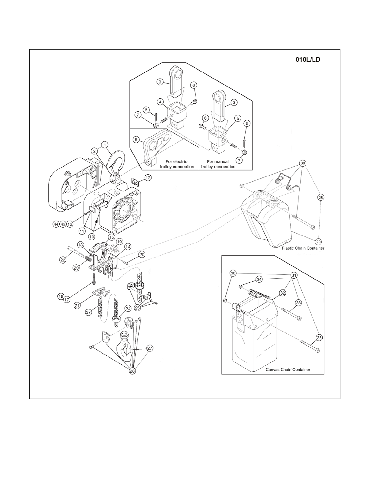
1.3 Hook and Chain Parts
Figure 3-1 Hook and Chain Parts
*Optional stainless steel chain container assembly not shown. See Figure No. 45 on part number chart for ordering information.
30
Page 12
Figure
1
Top Hook Assembly 1 2ASF005S5101
2 Hook Latch 1 2ASF005S1103
Suspender E (For Geared Trolley) –
Connection Yoke P (For Push Trolley) –
7
Yoke Bolt 1 2AFG005S9032
8
Slotted Nut 1 J1NL00910100
9
Split Pin 1 J1PW06025018
12
Plate A
1
ER2CS9123
13
Socket Bolt 1 J1BEE0601414
14
Shaft Clip
1
ER2CS9186
16
Chain Guide B 1 ER2CS9332
17
Socket Bolt 4 J1BEE0602525
18
Spring Lock Washer 4 J1WS07420060
20
Limit Lever Pin 1 ER2CS9338
21
Limit Lever Spring 1 WR2CS9357
Cushion Rubber – Standard
2
ER1CS9053
Stopper Assembly – Standard
ER1CS1041
Stopper Assembly – Nickel P la t e d
2AFG005S1041
Bottom Hook Complete Assemb ly –
Stainless Steel
27
Plastic Chain Contain er 1 ER2CS1401
28
Plastic Container Spring Assembly
1
2AFG005S1416
31
Socket Bolt 1 J1BEB0807528
32
Lever Nut 1 J1NU00920080
33
Socket Bolt 1 J1BEB0604508
34
Lever Nut 1 J1NU00920080
35
NP Load Chain 1 LCER2005NP-FG
35
ND Load Chain 1 LCER2005ND-FG
44
Spring Lock Washer 1 J1WS07420060
Stainless Steel Chain Contain er A ssembly
– maximum 23 ft. lift
No.
Part Name
Parts
Per
Hoist
1.3 Hook and Chain Parts
003L/LD 005L/LD
Suspender E (For Push Trolley) –
White Epoxy Paint
Suspender E (For Push Trolley) –
Nickel Plated
3
White Epoxy Paint
Suspender E (For Geared Trolley) –
Nickel Plated
5
White Epoxy Paint
Connection Yoke G (For Geared Trolley) –
6
White Epoxy Paint
Suspender T (For Motorized Trolley) –
White Epoxy Paint
10
Suspender T (For Motorized Trolley) –
Nickel Plated
11 Top Pin 2 WR2CS9121
15 Chain Guide A 1 ER2CS9331
19 Limit Lever 1 ER2CS9337
22
Cushion Rubber – Stainless Steel 2 27SF005S9117
23
Bottom Hook Complete Assemb ly –
White Epoxy Paint
24
25 Hook Latch 1 2ASF005S1103
Plastic Chain Contain er A ssembly
26
(Max. Lifting Height 20ft)
1
1 2AFG005S9027
1 2AFG005S9029
1
1
1
1 PBK2-C-FG
36FG0059004
37FG0059004
36FG0109004
37FG0109004
2AFG010S9031
2AFG010S9831
2AFG005S1011
2ASF005S5211
Canvas Chain Container Assembly
29
(Max. Lift Height 50ft)
30 Canvas Chain Container 1 ER2CS5405
43 Washer 1 J1WB07420060
45
Stainless Steel Chain Contain er A ssembly
– maximum 49 ft. lift
1 BK2C2-FG
7042201
1
7042202
31
Page 13
1.3 Hook and Chain Parts
Figure 3-2 Hook and C hain Parts
*Optional stainless steel chain container assembly not shown. See Figure No. 45 on part number chart for ordering information.
32
Page 14
2 Hook Latch 1 2ASF010S1103
Suspender E (For Manual Trolley) –
White Epoxy Paint
Suspender E (For Manual Trolley) –
Nickel Plated
Connection Yoke P (For Push Trolley) –
White Epoxy Paint
Connection Yoke G (For Geared Trolley) –
White Epoxy Paint
6
Yoke Bolt 1 2AFG005S9032
7
Slotted Nut 1 J1NL00910100
Suspender T (For Motorized Trolley) –
Suspender T (For Motorized Trolley) –
10
Top Pin
2
WR2CS9121
11
Plate A
1
ER2CS9123
13
Shaft Clip
1
ER2CS9186
14
Chain Guide A 1 ER2DS9331
15
Chain Guide B 1 ER2DS9332
17
Spring Lock Washer 4 J1WS07420080
18
Machine Screw With Spring Washer
4
J1AP45001212
19
Guide Roller 1 ER2DS9333
21
Limit Lever 1 ER2DS9337
22
Limit Lever Pin 1 ER2DS9338
23
Limit Lever Spring 1 WR2CS9357
Cushion Rubber – Stainless Steel
2
27SF010S9117
Stopper Assembly – Standard
ER1DS1041
Stopper Assembly – Nickel P la t e d
2AFG010S1041
Plastic Chain Contain er A ssembly
29
Plastic Chain Contain er 1 ER2DS1401
30
Plastic Container Spr in g A ssem b ly
1
2AFG010S1416
Canvas Chain Container Assembly
(Max. Lifting Height 50ft)
32
Canvas Chain Container 1 ER2DS5405
33
Socket Bolt 1 J1BEB0809028
34
Lever Nut 1 J1NU00920080
35
Socket Bolt 1 J1BEB0604508
37
ND Load Chain 1 LCER2010ND-FG
43
Washer
1
J1WB07420060
44
Spring Lock Washer 1 J1WS07420060
Stainless Steel Chain Contain er A ssembly –
Figure
No.
1 Top Hook Assembly 1 2ASF010S5101
3
4
5
8 Split Pin 1 J1PW06025018
White Epoxy Paint
9
Nickel Plated
12 Socket Bolt 1 J1BEE0601414
16 Socket Bolt 4 J1BEE0802525
20 Roller Pin 1 ER1CS9334
Part Name
Parts
Per
Hoist
1 36FG0109004
37FG0109004
1 2AFG005S9027
1 2AFG005S9029
1
2AFG010S9031
2AFG010S9831
1.3 Hook and Chain Parts
010L
Cushion Rubber – Standard 2 ER1DS9053
24
25
Bottom Hook Complete Assemb ly –
White Epoxy Paint
26
Bottom Hook Complete Assemb ly –
27 Hook Latch 1 2ASF010S1103
36 Lever Nut 1 J1NU00920060
Stainless Steel
28
(Max. Lifting Height 20ft)
31
37 NP Load Chain 1 LCER2010NP-FG
maximum 26 ft. lift
45
Stainless Steel Chain C o n tainer Assembly –
maximum 49 ft. lift
1
1
1 PBK2-D-FG
1 BK2D2-FG
1
2AFG010S1011
2ASF010S5211
7042203
7042205
33
Page 15

1.3 Hook and Chain Parts
Figure 3-3 Hook and Chain Parts
*Optional stainless steel chain container assembly not shown. See Figure No. 45 on part number chart for ordering information.
34
Page 16

1
Top Hook Assembly 1 2ASF020S5101
2 Hook Latch 1 2ASF020S1103
Suspender E (For Manual Trolley) –
7
Slotted Nut 1 J1NL00920160
8
Split Pin
1
J1PW06040030
Suspender T (For Motorized Trolley) –
White Epoxy Paint
Suspender T (For Motorized Trolley) –
Nickel Plated
10
Top Pin
2
2AFG020S9121
12
Socket Bolt 1 J1BEE0601414
13
Shaft Clip
1
ER2ES9186
14
Chain Guide A 1 ER2ES9331
16
Socket Bolt 4 J1BEE0803030
17
Spring Lock Washer 4 J1WS07420080
20
Roller Pin
1
ER1DL9334
21
Limit Lever
1
ER2ES9337
22
Limit Lever Pin 1 ER2EL9338
23
Limit Lever Spring 1 WR2CS9357
Limiting Plate – Standard 1 ER1ES9054
Limiting Plate – Stain less S t eel
27SF020S9118
Chain Spring – Stainless Steel
2AFG020L9112
Cushion Rubber – Standard
ER1ES9053
Cushion Rubber – Stainless Steel
27SF020S9117
Stopper Assembly – Standard
ER1ES1041
Stopper Assembly – Nickel P la t e d
2AFG020S1041
Bottom Hook Complete Assemb ly –
White Epoxy Paint
Bottom Hook Complete Assembly –
Stainless Steel
30
Hook Latch 1 2ASF020S1103
Plastic Chain Contain er A ssembly
(Max. Lifting Height 13ft)
32
Plastic Chain Contain er 1 ER2ES1401
Canvas Chain Container Assembly
35
Canvas Chain Container 1 ER2ES5405
36
Socket Bolt 1 J1BEB1010032
37
Lever Nut 2 J1NU00920100
39
NP Load Chain 1 LCER2020NP-FG
39
ND Load Chain 1 LCER2020ND-FG
Stainless Steel Chain Contain er A ssembly –
maximum 20 ft. lift
Stainless Steel Chain Contain er A ssembly –
maximum 39 ft. lift
46
Washer
1
J1WB07420060
47
Spring Lock Washer 1 J1WS07420060
Figure
No.
White Epoxy paint
3
Suspender E (For Manual Trolley) –
Nickel Plated
Connection Yoke P (For Push Trolley) –
4
White Epoxy Paint
Connection Yoke G (For Geared Trolley) –
5
White Epoxy Paint
6 Yoke Bolt 1 2AFG020S9032
9
11 Plat e A 1 ER2ES9123
15 Chain Guide B 1 ER2ES9332
18 Machine Screw With Spring Washer 4 J1AP46001212
19 Guide R o ller 1 ER1DL9333
24
Chain Spring – Standard
25
27
28
29
31
33 Plastic C ontainer Spring Asse m b ly 1 2AFG020S1416
34
(Max. Lifting Height 60ft)
38 Socket Bolt 1 J1BEB1007532
45
Part Name
Parts
Per
Hoist
1
1 2AFG020S9027
1 2AFG020S9029
1
1
1
1
1
1 PBK2-E-FG
1 BK2E2-FG
1
020L
36FG0209004
37FG0209004
2AFG020S9031
2AFG020S9831
ER1DL9051
2AFG020S1011
2ASF020S5211
7042204
7042206
35
1.3 Hook and Chain Parts
Page 17

1.4 Electric Parts (Single Speed)
Figure 4-1 Electric Parts (Single Speed)
36
Page 18

1.4 Electric Parts (Single Speed)
Limit Switch
Assembly
2
Socket Bolt
3
9091247
Spring Lock
4
Plate Assembly
1 ER2GHM05L5A2
ER2GHM10S5A2
ER2GHM20L5A2
5 Plate 1
ER2CS9441
ER2DS9441
ER2ES9441
6 Plate Screw
3
ER1BS9445
7 Transformer
1 TRF72V611
TRF73V611
Electromagnetic
3P
Terminal Block
11
Lead Wire
1 ER2GHM05L9A2
ER2GHM05S9A2
ER2GHM20S9A2
12
CH Meter
1
ECP91CHAE
CH Meter
15
Fuse 1
9006275
16
Fuse Holder
1
ECP92FZAA
17
Name Plate CH
1
ECP99CHAA
Terminal Block
6P
22
Fulcrum Pin
1
ER2CS9449
Suspender
24
Cover Belt
1
ER2CS9457
25
Socket Bolt
1
9091249
26
Plain Washer
1
ER1BS9436
Spring Lock
28
Packing C
1 ER2CS9117
ER2DS9117
ER2ES9117
33
Name Plate B
1 ER2BHM05S9A5
ER2BHM10S9A5
ER2BHM20S9A5
Pan Head Mach.
Figure
No.
Part Name
Parts
Per
Hoist
003L 005L 010L 020L
1
Complete
3
Washer
8
9
10
13
14 Rectifier 1 ECP93DIAA ECP94DIAA
18
23
Contactor
E-Stop
Contactor
Terminal Block
9P
Support
Cover
1 ER2CI1060
3 9012709
1 MGC23406C
1
1 ECP1303AB ECP1303AB
ECP1309AB
1 ECP99BKBA
1 ECP1306AD ECP1306AD
1 ER2CS9456
MGC13306F**
MGC14306C**
27
Washer
32 Controller Cover F 1 2AFG005S9104 2AFG010S9104 2AFG020S9104
34
Screw
35 Socket Bolt 4 J1BEE0504022 J1BEE0604024
36 Washer 1 J1WB07420050 J1WB07420060
1 9012709
2 9798534
**Refer to the alpha-numeric code on contactor. The code “S-U12” corresponds to MGD13306F.
The code “S-N11” corresponds to MGC13306H. The code “CLK-25J3” corresponds to MGC14306C.
37
Page 19

1.5 Electric Parts (Dual Speed)
Figure 5-1 Electric Parts (Dual Speed)
38
Page 20

Limit Switch
2
Socket Bolt
3
9091247
Spring Lock
Washer
4
LS Harness
1
ER2CI9554
6 Plate 1
ER2CI9441
ER2DI9441
ER2EI9441
7 Plate Screw
3
ER1BS9445
8 Bushing
1
ECP99JBAC
M, 2V 1 INV60FH24
INV615H24
INV622H24
F, 2V
INV60FH21
INV615H21
INV622H21
M, 4V
INV60FM24
INV615M24
INV622M24
14
Terminal Block 6P
1
ECP1306AD
17
Machine Screw
2
9798512
18
Fulcrum Pin
1
ER2CS9449
19
Cover Suspender
1
ER2CS9456
20
Cover Belt
1
ER2CS9457
21
Socket Bolt
1
9091249
22
Plain Washer
1
ER1BS9436
Spring Lock
24
Packing C
1 ER2CS9117
ER2DS9117
ER2ES9117
2V 1 2AFG005I2104
2AFG010I2104
2AFG020I2104
4V
2AFG005I1104
2AFG010I1104
2AFG020I1104
26
Controller Cover
1 2AFG005I9104
2AFG010I9104
2AFG020I9104
27
Resistor Cover
1 2AFG005I9185
2AFG010I9185
2AFG020I9185
2V 1 INV70EE16
INV718E16
INV718E16
4V
INV70EY16
INV718Y16
INV718Y16
Mach. Screw
Pan Head
Machine Screw
31
Socket Bolt
4 J1BEE0504022
J1BEE0604024
Toothed Lock
Washer
33
Washer
4 J1WB07420050
J1WB07420060
1.5 Electric Parts (Dual Speed)
Figure
No.
1
3
5 Plate Assembly
9 Inverter Assembly
10 Interface Board 1 ECP91KB02
11 Board Sup por t 1 ECP99BKAA
12 Transformer
13 Rectifier 1 ECP93DIAA
Part Name
Complete
Assembly
Parts Per
Hoist
1 ER2CI1060
3 9012709
M, 2V 1 ER2LHE05J5A2 ER2LHE10J5A2 ER2LHE20J5A2
F, 2V 1 ER2BHE05J5A2 ER2BHE10J5A2 ER2BHE20J5A2
M, 4V 1 ER2LHN05J5A2 ER2LHN10J5A2 ER2LHN20J5A2
F, 4V 1 ER2BHN05J5A2 ER2BHN10J5A2 ER2BHN20J5A2
F, 4V INV60FM21 INV615M21 INV622M21
2V
1
4V TRF32N612
005LD 010LD 020LD
TRF32C612
23
Washer
Controller Cover
25
Assembly
28 Braking Resistor
34
w/Spring Washer
29 Name Plate B 1 ER2BHM05I9A5 ER2BHM10I9A5 ER2BHM20I9A5
30
32
1 9012709
4 JAW44001212
2 9798534
4 J1WS07420050 J1WS07420060
39
Page 21

1.6 Power Supply and Pendant Parts
Figure 6-1 Power Supply and Pendant Parts (Plug Connection)
40
Page 22

Figure
Cord Support
(Wire Stop)
Mach. Screw
4
Socket Frame
1
2AFG005S9511
S
ER2CS2523
ER2ES2523
D
ER2CI2523
ER2CS2523
ER2EI2523
Tapping Flat
Screw
S
ER2CS2564
D
ER2CI2564
ER2EI2564
Mach. Screw
Washer
Mach. Screw
Socket Frame
Packing
Power Supply
Assembly
Power Supply
13
Plug 4P
1
ECP2304AD
Cable
Support Arm
Cable
14 Assembly
Pendant
S
16/4P
D
16/6P
S
SWD1100AAH
D
SWD2200AAH
S
ECP2108AA
D
ECP2108AB
Warning Tag
23
Tag Holder
1
E3S787003
Machine
25
Nut 1
9093414
No.
Part Name
Parts
Per
Hoist
1.6 Power Supply and Pendant Parts
005L/LD 010L/LD 020L/LD
1
2
W/Spring
Washer
Socket Frame
3
Complete
Assembly
Socket 4P
5
Assembly
6
Head Mach.
10
11
7
8
9
12
14
Socket 8P
Assembly
W/Spring
W/ Spring
Washer
Cable 4C
Cable 4C
1 ER1BS9534
2 J1AP45001212
S
1
D 2AFG005I4511 2AFG010I4511 2AFG020I4511
1
8 ES558003
1
2 ES650005S
6 J1AP45002020
1 ER2CS9512
1 ZBZA12CH1000
ft 16/4
1 ER1BS9541
2AFG005S4511 2AFG020S4511
15
Support 12
Assembly
Cable Hanger
17
W/Cord
18
Complete
Assembly
19 Pendant Cord
Pendent
20
Assembly
21 Plug 8P
22
PB
24
Screw
1 ES822003
A/R ES1527003
S
1
D ZB20025I1000
ft
1
1
1 WTAG7
1 J1AP24002608
ZB10025H1000
Note: A/R = As required, one every 5 ft. of Power Supply Cable.
41
Page 23

This Page Intentionally Left Blank
42
Page 24

S = Single Speed
W = SS/SS = Single Speed Hoist, Single Speed Tr olle y
D = Dual Speed
X = SS/DS = Single Speed Hoist, Dual Speed Trolley
PC = Plug Connection
Y = DS/SS = Dual Speed Hoist, Single Speed Trolley
2V = 208/230 Volt Models
Z = DS/DS = Dual Speed Hoist, Dual Speed Trolley
4V = 460 Volt Models
2.0 MR2 Parts List
When ordering parts, please provide the trolley code number, lot number and serial number located on the hoist
nameplate (see fig. below).
Reminder: To aid in ordering parts and product support, record the trolley code number, lot number and serial
number in the space provided on the cover of this manual.
MR2 Series Name Plate
The parts list is arranged into the following sections:
Section 1/4 to 2 Ton Page
2.1 Electric Parts – 1/4 to 2 Ton………………………….………………………………...………….. 44
2.2 Pendant Parts – 1/4 to 2 Ton ……………………………………………………………………… 48
2.3 Power Supply Parts – 1/4 to 2 Ton ……………………………………………………….………. 50
2.4 Side Plates and Suspension Parts – 1/4 to 2 Ton ………………………………………..…….. 52
2.5 Motor Parts – 1/4 to 2 Ton ………………………………………….………………….………….. 54
In the column "Parts Per Trolley" a designator is used for parts that apply only to a particular model or option.
Refer to Chapter 3, Section 2 for MR2 trolley model numbers and additional descriptions.
The designators are:
43
Page 25

2.1 Electric Parts – 1/4 to 2 Ton (S ingle Speed)
Figure 1-1 Electric Parts (Single Speed)
44
Page 26

1
Connection Box Assembly
1
7038101
7038102
2 Holder A
1
ECP5924AA
5 Holder Nut 2 ECP5924AD
6 Cord Cover 1 E6F630010S
11
Connection Box Pa cking
1
MR1DS9421
13
Spacer
4
MS517010
15
Complete Plate Ass embly
1
MR2RHM10M1A5
16
Plate
1
MR2DS5445
21
Terminal 16P 1 ECP1416AA
23
Electromagnetic Contactor
1
MGC22306B
24
E-Stop Contactor 1 MGC12306B
25
Machine Screw With Spring Washer
4
MS554010
26
Power Supply Cable Assembly
1
MR2DS1759
MR2ES1759
27
Holder A
1
ECP5924AA
28
Holder B
1
ECP5924AB
29
Packing
1
ECP5924AC
30
Holder Nut 1 ECP5924AD
31
Cable Packing
1
ECP6912AA
ECP6916AA
32
S.O. Cord 4C 1 16/4
14/4
33
Plug 4P 1 ECP2304AD
ECP2304AF
34
Control Cable Assembly
1
MR2DS1768
MR2ES1768
35
Holder A
1
ECP5924AA
36
Holder B
1
ECP5924AB
37
Packing
1
ECP5924AC
38
Holder Nut 1 ECP5924AD
39
Cable Packing 1 ECP6916AA
46
Wiring Diagr am 1 EWG3110H01
47
Name Plate B 1 MR2SHM10S9A8
48
Name Plate C
1
MR2SHM10S9A7
MR2SHM20S9A7
Parts
2.1 Electric Parts– 1/4 to 2 Ton (Single Speed)
Parts
Figure No. Part Name
3 Holder B 2 ECP5924AB
4 Packing 2 ECP5924AC
7 Machine Screw With Spring Washer 8 J1AP45001010
9 Connection Box 1 3AFG010S9401
10 Connection Box Cov e r 1 3AFG010S9411
12 Machine Screw With Spring Washer 4 J1AP45001010
14 Machine Screw With Spring Washer 4 J1AP48002020
17 Machine Screw With Spring Washer 3 MS555010
18 Machine Screw With Spring Washer 2 MS556010
19 Machine Screw With Spring Washer 2 MS556010
Per
Trolley
1 Ton 2 Ton
20 Machine Screw With Spring Washer 2 MS556010
40 S.O. Cord 6C 1 16/6P
41 Plug 8P 1 ECP2108AC
42 Socket 8P Assembly 1 MR2DS2811
43 Plate P 1 ECP5924AH
44 Cord Cover Packing 2 MS527010
45 Warning Seal E (Electric Shock) 1 ER2CS9936
Name Plates for 1/8, 1/4, 1/2 & 1 1/2 Ton Capacities
Figure
No.
48 Name Plate C 1 MR2SHM01S9A7 MR2SHM03S9A7 MR2SHM05S9A7
Part Name
Per
Trolley
1/8 Ton 1/4 Ton 1/2 Ton 1 1/2 Ton
MR2SHM15S9A7
45
Page 27

2.1 Electric Parts – 1/4 to 2 Ton (Dual Speed)
Figure 1-2 Electric Parts (Dual Speed)
46
Page 28

Parts Per
2V 1 7038201
7038202
4V
7038203
7038204
2 Holder A
1
ECP5924AA
3 Holder B
2
ECP5924AB
4 Packing
2
ECP5924AC
5 Holder Nut
2
ECP5924AD
6 Cord Cover
1
E6F630010S
7 Machine Screw With Spring Washer
8
J1AP45001010
9 Connection Box 1 3AFG010S9401
10
Connection Box Cover 1 3AFG010S9411
11
Connection Box Pa cking 1 MR1DS9421
12
Machine Screw With Spring Washer
4
J1AP45001010
13
Spacer
4
MS517010
14
Machine Screw With Spring Washer
4
J1AP48002020
20
Machine Screw With Spring Washer
4
MS555010
2V
INV604E31
4V
INV604N31
2V
INV904E34
4V
INV904Y34
23
Board Support
1
ECP99BKAB
24
Machine Screw With Spring Washer
2
MS555010
25
Machine Screw With Washers
2
J1AW24000808
26
Machine Screw With Spring Washer
2
MS556010
27
Interface Board 1 ECP91KB12
29
Terminal 3P
1
ECP1403AA
30
Machine Screw With Spring Washer
4
MS554010
31
Power Supply Cable Assembly
1
MR2DS1759
MR2ES1759
32
Holder A
1
ECP5924AA
38
4P Plug 1 ECP2304AD
ECP2304AF
39
Control Cable Assembly
1
MR2DI1768
MR2EI1768
40
Holder A
1
ECP5924AA
41
Holder B
1
ECP5924AB
42
Packing
1
ECP5924AC
43
Holder Nut
1
ECP5924AD
44
Cable Packing
1
ECP6916AA
45
S.O. Cord 6C
1
16/6P
46
8P Plug
1
ECP2108AC
2V
MR2DI1811
4V
MR2DI2811
48
Plate P
1
ECP5924AH
49
Cord Cover Packing 2 MS527010
50
Warning Seal E (Electric Shock)
1
ER2CS9936
51
Wiring Diagr am 1 EWG3DD0H01
52
Name Plate B 1 MR2SHM10S9A8
Parts
Trolley
53
Name Plate C
1
MR2SHM01S9A7
MR2SHM03S9A7
MR2SHM05S9A7
MR2SHM15S9A7
2.1 Electric Parts– 1/4 to 2 Ton (Dual Speed)
Figure No. Part Name
1 Connection Box Assembly
15 Complete Plate Assembly
16 Plate 1 MR2DI9441
17 Plate B 1 MR2DI9443
18 Machine Screw With Spring Washer 3 MS555010
19 Machine Screw With Washers 2 J1AW24000808
21 VFD Assembly
22 Braking Resistor
Trolley
2V
4V MR2IHN10R1A5 MR2IHN20R1A5
1
1
1
1 Ton 2 Ton
MR2IHE10R1A5 MR2IHE20RIA5
33 Holder B 1 ECP5924AB
34 Packing 1 ECP5924AC
35 Holder Nut 1 ECP5924AD
36 Cable Packing 1 ECP6912AA ECP6916AA
37 S.O. Cord 4C 1 16/4 14/4
47 Socket 8P Assembly
53 Name Plate C 1 MR2SHM10S9A7 MR2SHM20S9A7
1
Name Plates for 1/8, 1/4, 1/2 & 1 1/2 Ton Capacities
Figure
No.
Part Name
Per
1/8 Ton 1/4 Ton 1/2 Ton 1 1/2 Ton
47
Page 29

2.2 Pendant Parts – 1/4 to 2 Ton
Figure 2-1 Pendant Parts
48
Page 30

W
ZB1102AI1000
X
ZB1202AI1000
Y
ZB2102AI1000
Z
ZB2202AI1000
Washer
8 Nut
1
9093414
W, PC
ECP2108AB
X, Y, Z,
PC
W
SWD2110ABH
X
SWD2120ABH
Y
SWD2210ABH
Z
SWD2220ABH
12
Bar Holder
1
MR1DS9481
13
Cord Strain Relief Stopper
1
E6L614010S
2.2 Pendant Parts – 1/4 to 2 Ton
Figure
No.
1
4
5 Warning Tag PB 1 WTAG7
6 Tag Holder 1 E3S787003
7
9 Plug 8P
10
11 Bar Holder Assembly 1 MR1DS1481
14
15 Socket Bolt 2 J1BEE1002828
16 Spring Washer 2 J1WS07420100
Part Name
Push Button Cord 6C/7C/8C
Complete Assembly
Push Button Cord 6C W
Push Button Cord 8C X, Y, Z 16/8P
Machine Screw With Spring
5 Push Button Switch
Assembly
Machine Screw w/Spring
Washer
Parts Per
Trolley
1
1
1 J1AP24002608
1
1
2 E6F151003
1 Ton 2 Ton
ECP2108AD
16/6P
49
Page 31

2.3 Power Supply Parts – 1/4 to 2 Ton
Figure 3-1 Power Supply Parts
50
Page 32

1
Power Supply Cable 4C Assembly
1
ZBZC12AH1100
ZBZC12BH1100
2 Cable Packing
1
ECP6914AA
ECP6916AA
3 Cable Support 14 Assembly
1
M3ES0101724
10
Bolt
1
9093328
11
Spring Lock Washer 1 9012711
12
Nut
1
9093424
13
Wire Guide Assembly 1 MR1DS1493
14
Wire Guide 1 MR1DS9493
15
Wire Stopper 1 MR1DS9496
16
Machine Screw With Spring Washer
2
M6F554010
17
Bolt
1
9093328
18
Spring Lock Washer 1 9012711
19
Nut
1
9093424
20
Support Bar Holder (Plate)
1
MR1DS9501
21
Bolt
2
9093329
22
Spring Lock Washer 2 9012711
Cable Hanger Pusher (Beam 75mm)
1
3AFG010S9511
28
Packing
2
ECP5924AC
29
Cable Packing 2 ECP6912AA
30
Trolley Cable 6C 1 16/6
2.3 Power Supply Parts – 1/4 to 2 Ton
Figure No. Part Name
5 Power Supply Cable 4C 1 14/4 12/4
6 Cable Hanger 14 Assembly A/R ES1527003 MS1733020
7 Cable Support Bar Assembly 1 MR1DS1491
8 Cable Sup p o r t Bar 1 MR1DS9491
9 Cable Support Arm 1 MR1DS9492
23
24 Socket Bolt With Spring Washer 2 J1BGE1002828
25 Trolley Cable 6C Assembly 1 MR2DS1793
26 Holder A 2 ECP5924AA
27 Holder B 2 ECP5924AB
Cable Hanger Pusher (Beam 100150mm)
Parts
Per
Trolley
1 3AFG010S9512
1 Ton 2 Ton
*A/R = As Required, one for every 5 ft of power Supply Cable.
51
Page 33

2.4 Side Plates and Suspension Parts – 1/4 to 2 Ton
Figure 4-1 Side Plates and Suspension Parts
52
Page 34

Parts
Trolley
Side Plate G Assembly – Standar d Wheels
3AFG010S5201
3AFG020S5201
Side Plate G Assembly – Stainless Steel
Wheels
Track Wheel G Assembly – Standard
MS1101010
MS1101020
Track Wheel G Assembly – Stainless Steel
35MW0105101
35MW0205101
4
Washer 2 MS104010
MS104020
Snap Ring – Standard
9047115
9047120
Snap Ring – Stainless Steel
J1SS10000015
J1SS10000020
Side Roller Assembly – Standard
MR1DS1211
MR1ES1211
Side Roller Assembly – Stainless Steel
3AFG010S2211
3AFG020S2211
Wheels
Track Wheel S Assembly – Standard
MS1102010
MS1102020
Track Wheel S Assembly – Stainless Steel
35MW0105102
35MW0205102
14
Washer 2 J1WB07410080
J1WB07410100
Snap Ring – Standard
9047115
9047120
Snap Ring – Stainless Steel
J1SS10000015
J1SS10000020
Suspension Shaft Assembly – Standard
Shaft
Suspension Shaft Assembly – Nickel Plated
Suspension Sha ft – Nickel Plated
3AFG010S9115
3AFG020S9115
18
Thick Spacer
3
MSF116010
T7G116030
22
Thick Spacer L
2
MR1DS9110
MR1ES9110
24
Thin Spacer 8 MSF117010
MSF117020
Fixing Shaft – Standard
MR1DS9131
MR1ES9131
Fixing Shaft – Nickel Plated
3AFG010S9131
3AFG020S9131
33
Bumper Lug
4
3AFG010S9361
3AFG020S9361
34
Spring Washer 4 J1WS07420080
35
Nut
4
J1NA00920080
2.4 Sid e Plat es and Susp ens ion P arts – 1/4 to 2 Ton
Figure
No.
2
3
5
6
8 Bolt 4 J1BAE0803030 J1BAE1003535
9 Spring Lock Washer 4 J1WS07420080 J1WS07420100
10 Nut 4 J1NA00920080 J1NA00920100
Side Plate S Assembly – Standard Wheels
12
Side Plate S Assembly – Stainless Steel
13
15
16
Shaft
Suspension Sha ft – Standard
17
Part Name
Per
1
2
2
4
1
2
2
1
1
1 Ton 2 Ton
3AFG010S5801 3AFG020S5801
3AFG010S5202 3AFG020S5202
3AFG010S5802 3AFG020S5802
3AFG010S2101 3AFG020S2101
3AFG010S3101 3AFG020S3101
MSF115010 MSF115020
19 Bolt 1 3AFG010S9103 3AFG020S9103
20 Slotted Nut 1 J1NL00910100
21 Split Pin 1 J1PW06025018
25 Shaft Stopper 1 T6G156020 MS164020
26 Split Pin 1 J1PW06040020
27
28 Split Pin 2 J1PW06050040
30 Spring Washer 8 J1WS07420080
31 Nut 8 J1NA00920080 J1NA00920100
32
Bumper
36
Bolt
37
Square Spacer
1
4 MR1DS9631
8 J1BEB0803535 J1BEB1004526
4 MS006010 MS006020
53
Page 35

Assembly – Standard Sh af t
Extended Suspension Shaft
Shaft
Extended Suspension Shaft
– Standard
Extended Suspension Shaft
22
Thick Spacer L
2
MR1DS9110
MR1ES9110
23
Fixing Spacer
2
M7SE010S9182
M7SE020S9182
24
Thin Spacer
8
MSF117010
MSF117020
Fixing Shaft – Standard
MR1DS9141
MR1ES9141
Fixing Shaft – Nickel Plated
3AFG010S9141
3AFG020S9141
Extended Suspension Shaft Ass emblies
Figure
No.
16
Part Name
Extended Suspension Shaft
Assembly – Nickel Plated
Parts Per
Trolley
1 37FG010S1121 37FG020S1121
1 37FG010S3121 37FG020S3121
1 Ton 2 Ton
17
18 Thick Spacer 9 MSF116010 T7G116030
– Nickel Plated
19 Bolt 1 3AFG010S9103 3AFG020S9103
20 Slotted Nut 1 J1NL00910100
21 Split Pin 1 J1PW06025018
27
28 Split Pin 2 J1PW06050040
1
1
MSF181010 MSF181020
3AFG010S9181 3AFG020S9181
54
Page 36

This Page Intentionally Left Blank
55
Page 37

2.5 Motor Parts – 1/4 to 2 Ton
Figure 5-1 Motor Parts
56
Page 38

2
Gear Box Packing 1 MR1DS9248
3
Set Pin
2
MR1DS9249
6
Washer 4 J1WB07400080
8 Ball Bearing 1 9001004
9 Brake Drum Assembly
1
MR1DS5261
10
Brake Spring 1 MS304010
11
Bumper
1
MR1DS9265
12
Guard
1
MR1DS9281
13
Motor Shaft With Rotor
1
MR1DS5291
14
Oil Seal
1
MR1DS9293
18
Terminal Cover 1 MR1DS9324
19
Terminal Cover Packing
1
MR1DS9325
20
Coil Cover 1 MR1DS9326
21
Machine Screw With Spring Washer
4
J1AP45001010
22
Machine Screw With Spring Washer
2
MS556010
23
Machine Screw With Spring Washer
1
MS555010
24
Terminal 6P 1 ECP1306AB
25
Terminal Plate Holder
1
MR1DS9855
Gear
29
Gear #2
1
MR1DS9241
MR1DL9241
MR1DS9241
MR1DL9241
30
Gear #3 1 MR1DS9242
MR1ES9242
31
O Ring
1
9013316
32
Spacer
1
MR1DS9244
Ball
Ring
35
O Ring
1
MR1DS9254
Snap
Ball
Bearing
2.5 Motor Parts – 1/4 to 2 Ton
Figure
No.
4 Bolt 4 J1BAE0802525
5 Spring Lock Washer 4 J1WS07420080
7 Motor Assembly 1 3AFG010S1321
15 Motor Cover Assembly 1 3AFG010S1301
16 Socket Bolt 4 J1BEE0802222
17 Motor Frame With St ato r 1 3AFG010S5321
Part Name
Parts
Per
Trolley
1 Ton 2 Ton
26 Flat Head Tapping Screw 2 9096529
27 Motor Data Plate 1 IMNBH04VT
38 Washer 1 J1WD07420050
Figure
No.
28
33
34
36
37
Part
Name
Assembly
Bearing
Snap
Ring
Parts
Per
Trolley
1 MR1DS1241 MR1DL1241 MR1ES1241 MR1EL1241
1 9001211
2 9047120
1 9047120
1 E2D238125
1 Ton
S/SD
1 Ton
L/LD
2 Ton
S/SD
2 Ton
L/LD
57
Page 39

This Page Intentionally Left Blank
58
Page 40

3.0 TS2 Parts List
When ordering parts, please provide the hoist code number, lot number and serial number located on the hoist
nameplate (see fig. below).
Reminder: To aid in ordering parts and product support, record the hoist code number, lot number and serial number in
the space provided on the cover of this manual.
TS2 Series Nameplate
The parts list is arranged into the following sections:
Section ½ to 2 Ton Page
3.1 TS2 Push Trolley Parts – 1/4 to 2 Ton……………………………………………………………….….….…...60
3.2 TS2 Geared Trolley Parts – 1/4 to 2 Ton………………………………………………………………………..62
59
Page 41

3.1 TS2 Push Trol ley Par ts – 1/4 to 2 Ton
TS2 Push Trolley 1/4 to 2 Ton
60
Page 42

Parts
Trolley
Side Plate S Assembly –
Side Plate S Assembly –
Stainless Steel Wheels
Name plate B
T6G800005P
T6G800010P
T6G800020P
Name plate B – ¼ Ton
80434
Track wheel S Assembly –
Standard
Stainless Steel
4
Slotted nut 4 J1NL00910100
5
Split pin 4 J1PW06020016
6
Track wheel washer
4 MS104010
MS104020
7
Snap ring 4
J1SS10000015
J1SS10000020
Standard Shaft
Suspension Shaft Assembly –
Nickel Plated Shaft
Suspension Shaft – Standard
T7G115005
T7G115010
T7G115020
Suspension Shaft – Nickel Plated
37FG0059115
37FG0109115
37FG0209115
9
Thick spacer (qty)
X
T7G116005(4)
T7G116010(6)
T7G116020(6)
10
Thin spacer (qty)
X
T7G117005(10)
T7G117010(9)
T7G117020(8)
12
Shaft stopper pin
2
T6G156005
T6G156010
T6G156020
13
Split pin
2
J1PW06032020
J1PW06040020
Suspender E & G –
Nickel Plated
36FG0051136
{8.01 to 12.00”}
36FG0101136
{8.01 to 12.00”}
37FG0051136
37FG0101136
{8.01 to 12.00”}
{8.01 to 12.00”}
37FG0059136
{8.01 to 12.00”}
37FG0109136
{8.01 to 12.00”}
T7GA0109137
27
Shaft Stopper Pin
*2
T6G156005
T6G156010
T6G156020
28
Split Pin
*2
J1PW06032020
J1PW06040020
29
Thin Spacer
X
T7G117005 (10)
T7G117010 (10)
T7G117020 (10)
T7G116010
{8.01 to 12.00”} - (7)
3.1 TS2 Push Trol ley Par ts – 1/4 to 2 Ton
Figure
No.
1
2
3
14
Part Name
Standard Wheels
Track wheel S Assembly –
Suspension Shaft Assembly –
8a
8
White Epoxy Paint
Suspender E & G –
Per
2
1
4
1
1
1
1/2 Ton 1 Ton 2 Ton
37FG0055112 37FG0105112 37FG0205112
37FG0055812 37FG0105812 37FG0205812
T6G5102005 T6G5102010 T6G5102020
37TW0055102 37TW0105102 37TW0205102
36FG0051115 36FG0101115 36FG0201115
37FG0051115 37FG0101115 37FG0201115
36FG0059004 36FG0109004 36FG0209004
37FG0059004 37FG0109004 37FG0209004
Suspension Shaft Assembly
Extended – Standard Shaft
21
Suspension Shaft Assembly
Extended – Nickel Plated Shaft
Suspension Shaft – Standard
22
Suspension Shaft – Nickel Plated
26 Fixing Spacer 2
30 Thick Spacer X T7G116005 (7)
1
1
{4.01 to 8.00”}
36FG0051181
{4.01 to 8.00”}
37FG0051181
{8.01 to 12.00”}
T7PA0059136
{4.01 to 8.00”}
T7PA0059181
{4.01 to 8.00”}
37FG0059181
T7PA0059137
{4.01 to 8.00”}
T7PA0059182
{8.01 to 12.00”}
{5.01 to 8.00”}
36FG0101181
{5.01 to 8.00”}
37FG0101181
{8.01 to 12.00”}
T7GA0109136
{5.01 to 8.00”}
T7GA0109181
{5.01 to 8.00”}
37FG0109181
{5.01 to 8.00”}
T7GA0109182
{8.01 to 12.00”}
{5.01 to 8.00”} - (5)
36FG0201181
{6.03 to 12.00”}
37FG0201181
{6.03 to 12.00”}
T7GA0209181
{6.03 to 12.00”}
37FG0209181
{6.03 to 12.00”}
T7GA0209182
T7G116020 (11)
*Quantity is 1 for 2 Ton.
61
Page 43

3.2 TS 2 Gear ed Troll ey Part s – 1/4 to 2 Ton
TS2 Geared Trolley 1/4 to 2 Ton
62
Page 44

Figure No.
Part Name
Parts Per Trolley
1 Ton
2 Ton
Side Plate S Assembly –
Side Plate S Assembly –
Stainless Steel Wheels
2
Name plate B**
1
T6G800010G
T6G800020G
Track wheel S Assembly – Standard
T6G5102010
T6G5102020
Track wheel S Assembly – Stainless Steel
37TW0105102
37FG0205812
4
Track wheel washer
4
MS104010
MS104020
5
Snap ring 4 J1SS10000015
J1SS10000020
Track wheel G Assembly – Standard
T6G5101010
T6G5101020
Track wheel G Assembly – Stainless Steel
37TW0105101
37TW0205101
Side Plate G Assembly – Stainless Steel
Wheels
8
Hand chain guide Assembly 1 37FG0105125
Hand wheel - Standard 1 T6G123010
Hand Wheel - White Epoxy Paint
37FG0109123
10
Washer
1
J1WB07410120
11
Split pin
1
J1PW06030018
13
Pinion 1 T7GC121010
T7GB121020
14
Hand chain
1
K7RA0500000
Suspension Shaft Assembly –
Standard Shaft
Suspension Shaft Assembly –
Nickel Plated Shaft
Suspension Shaft – Standard
T7G115010
T7G115020
Suspension Shaft – Nickel Plated
37FG0109115
37FG0209115
16
Shaft stopper pin
2
T6G156010
T6G156020
17
Split pin 2 T6GA0109117(9)
T6GA0209117(8)
19
Thin spacer (qty)
X
T7G117010(9)
T7G117020(8)
Suspender E – White Epoxy Paint
36FG0109004
36FG0209004
Suspender E – Nickel Plated
37FG0109004
37FG0209004
36FG0101136
{8.01 to 12.00”}
{8.01 to 12.00”}
37FG0109136
{8.01 to 12.00”}
33
Shaft Stopper pin
*2
T6G156010
T6G156020
34
Split Pin
*2
J1PW06032020
J1PW06040020
35
Thin Spacer
X
T7G117010 (10)
T7G117020 (10)
T7G116010
{8.01 to 12.00”} - (7)
3.2 TS2 Geared Trolley Parts – 1/4 to 2 Ton
Standard Wheels
1
3
6
Side Plate G Assembly
7
9
12 Lever nut 1 J1NU00920120
15a
1
2
2
1
1
37FG0105112 37FG0205112
37FG0105812 37FG0205812
37FG0105111 37FG0205111
37FG0105811 37FG0205811
36FG0101115 36FG0201115
37FG0101115 37FG0201115
15
18 Thick spacer (qty) X T7G116010(6) T7G116020(6)
23
Suspension Shaft Assembly
Extended – Standard Shaft
27
Suspension Shaft Assembly
Extended – Nickel Plated Shaft
Suspension Shaft – Nickel Plated
32 Fixing Spacer 2
Suspension Shaft – Standard
28
1
1
{4.01 to 8.00”}
36FG0101181
1
1
37FG0101136
{4.01 to 8.00”}
37FG0101181
{8.01 to 12.00”}
T7PA0109136
{4.01 to 8.00”}
T7PA0109181
{4.01 to 8.00”}
37FG0109181
T7GA0109137
{5.01 to 8.00”}
T7GA0109182
{8.01 to 12.00”}
36FG0201181
{6.03 to 12.00”}
37FG0201181
{6.03 to 12.00”}
T7GA0209181
{6.03 to 12.00”}
37FG0209181
{6.03 to 12.00”}
T7GA0209182
36 Thick Spacer X
37 Hand Chain Master Link 1 C1FA0159843N
{5.01 to 8.00”} - (5)
T7G116020 (11)
* Quantity is 1 for 2 Ton.
** For ¼ and ½ Ton capacities, Name Plate B will be relabeled at the factory.
63
Page 45

www.harringtonhoists.com
Harrington Hoist s, Inc. Harrington Hoi sts – Western Division
401 West End Avenue 2341 Pomona Rd. No. 103
Manheim, PA 17 54 5-1703 Corona, CA 928 80-6973
Phone: 717-665-2000 Phone: 951-279-7100
Toll Free: 800-233-3010 Toll Fr ee: 800-317-7111
Fax: 717-665-2861 Fax: 951-279-7500
ER2FGSUP
64
 Loading...