

Harrington Hoists MR2, TS2 User Manual
This equipment should not be installed, operated or
all the contents of this manual. Failure to read and comply
with the contents of this manual can result in serious bodily
EFFECTIVE: March 11, 2013
ELECTRIC
CHAIN HOIST
NER2 / MR2 / TS2
FOOD GRADE MODEL
1/4 Ton through 2 Ton Capacit i es
Code, Lot and Serial Number
maintained by any person who has not read and understood
injury or death, and/or property damage.

IMPORT ANT INFORMATION ON HOW TO USE THIS MANUAL
This OWNER’S MANUAL SUPPLEMENT for Food Grade Hoists is intended for use in combination with:
“Owner’s Manual for Electric Chain Hoist ER2 and NER2 Series 1/8 through 5 Ton C apaci ty”
“Owner’s Manual for Motorized Trolley MR2 Series 1 Ton through 20 Ton Capacity”
“Owner’s Manual for Manual Trolley TS2/TF2 Ser ies ½ Ton through 5 Ton Capac ity ”
Refer to the Main Table of Contents below to determine the location(s) of information pertaining to your hoist.
References to the Owner’s Manuals listed above will be designated by the use of the acronym “ER2OM”, “MR2OM”,
“TF2TS2OM”.
Main Table of Contents
Chapters Page Number
I Conformance Clarification Statement…………………………………………3
II NER2 Electric Chain Hoist………………………………………………..……….4
III MR2 Motorized Trolley……………………………………………………..……..11
IV TS2 Manual Trolley……………………………………………………..…………15
V Parts List……………………………………………………………………………..21
1.0 NER2……………………………………………………………………………..21
2.0 MR2……………………………………………………………………………….43
3.0 TS2………………………………………………………………………………..59
2

I Conformance Clarificat ion Sta t ement
1.1 Food Grade Options
Harrington ER2 Food Grade hoists are designed for applications which require food grade hoists. All
products should be tested for suitability on a particular application prior to actual use. The
occupational Safety and Health Act of 1970 places the burden of compliance with t he
owner/employer, not the manufacturer. Many OSHA requirements are not concerned or connected
with the manufactured product but are associated with the final installation. It is the owner’s
and user’s responsibility to determine the suitability of a product for any particular use. It is
recommended that all applicable industry, trade association, federal, state and local regulations be
checked. Read all operating instructions and warnings before operation.
1.2 Corrosion Resistance:
Standard Product Features and Benefits
• Nickel plated load chain
• The formulation of NEVASTANE HT/AW WHITE greases complies with the FDA chapter
21 CFR, 178.3570.
• The formulation of NEVASTANE SL oils complies with the FDA chapter 21 CFR,
178.3570.
• White epoxy painted hoist body, hooks, and suspenders
• ASME H4 classification
• Stainless steel and nickel plated components
Optional Product Features and Benefits
• Nickel Diffused Load Chain
• Stainless Steel Trolley Wheels
• Nickel Plated shafts and suspenders
• NEMA 4 pendant
• Pendant Cover
• Stainless Steel bottom hook
• Stainless Steel chain spring and limiting plate
• Stainless Steel chain container
3

II NER2 Electric Chai n Hois t
Section Page Number
1.0 Important In formation and Warnings … …… ………… …………………………………………..…….ER2OM
1.1 Terms and Summary
1.2 Warning Tags and Labels
2.0 Technical Information…………………………………………………………………………...……………6
2.1 Specifications
2.2 Dimensions
3.0 Preoperational Procedures …………………………………………………………………………..
3.1 Gearbox
3.2 Chain
3.3 Mounting Location
3.4 Mounting the Hoist
3.5 Electrical Connections
3.6 VFD Setup (Dual Speed Only)
3.7 Preoperational Checks and Trial Operation
4.0 Operation …………………………………………………………………..……………………….....E
4.1 Introduction
4.2 Shall’s and Shall Not’s for Operation
4.3 Hoist Controls
5.0 Inspection ……………………………………………………………………………………..…..…..
ER2OM
ER2OM
R2OM
5.1 General
5.2 Inspection Classification
5.3 Frequent Inspection
5.4 Periodic Inspection
5.5 Occasionally Used Hoists
5.6 Inspection Records
5.7 Inspection Methods and Criteria
4

Section Page Number
6.0 Maintenance & Handling …………………………………… ...…………………………………………ER2OM
6.1 Count/Hour Meter
6.2 Lubrication – Load Chain, Hooks and Suspension………………………..….8 and ER2OM
6.3 Lubrication – Gearbox…………………………………………………….....…..8 and ER2OM
6.4 Motor Brake
6.5 Load Chain……………………………………………………………………....10 and ER2OM
6.6 Friction Clutch and Mechanical Load Brake with Friction Clutch
6.7 Storage
6.8 Outdoor Installation
6.9 Operational Environment
7.0 Troubleshooting ……………………………………………… ………………………………………….ER2OM
8.0 Warranty ………………………………………………………………………………………………….ER2OM
9.0 Parts List ……………………………………………… …………………… ……… …………………… ……... 21
5
2.1 Specifications
Temperature range:
-4° to +104°F (-20° to +40°C)
Humidity:
85% or less Noise Level:
85 dB or less (A scale: measured 1 meter away from electric chain hoist
Enclosure Rating:
Hoist Meets IP 55
Hoist Duty Rating:
ISO M4/M5; ASME H4
Rating:
360 starts per hour
120/240 starts per hour
Rating:
Lift
Button
Cord
L
Diameter
(mm)
x
Weight for
Additional
1/4
NER2003L-FG
1/2
NER2005L-FG
1
NER2010L-FG
1.2
4.8
2.5
7.7 x 1
104
0.89
2
NER2020L-FG
2.4
8.6
4.2
10.2 x 1
161
1.6
1/4
NER2003LD-FG
1/2
NER2005LD-FG
1
NER2010LD-FG
1.2
5.1
2.7
7.7 x 1
99
0.89
2
NER2020LD-FG
2.4
9.1
4.5
10.2 x 1
161
1.6
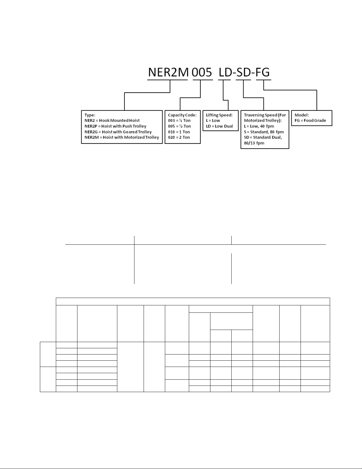
2.1.1 Product Code
2.1.2 Operating Conditions and Environment
Supply Voltage: Single Speed Standard: Reconnectable 208/230-3-60 & 460V-3-60
Dual Speed Standard: 208/230V-3-60 or 460V-3-60
Single Speed Dual Speed
Intermittent Duty
Short Time Duty
60% ED
60 min. 30/10 min.
Table 2-1 Hoist Specifications
Cap.
(Tons)
Single
Speed
Dual
Speed
Product Code
Standard
(ft)
10 8.2
Push
(ft)
Lifting
Speed
(ft/min)
15 0.75 3.4 1.7 6.0 x 1 71 0.54
14
15/2.5 0.75 3.6 1.8 6.0 x 1 68 0.54
14/2.5
Lifting Motor 3 Phase 60 Hz
Output
(Hp)
Rated Current
(amps)
@208 -
230V
@460V
40/20% ED
Load
Chain
Chain Fall
Lines
Net
Weight
(lbs)
One Foot
of Lift
(lbs)
6
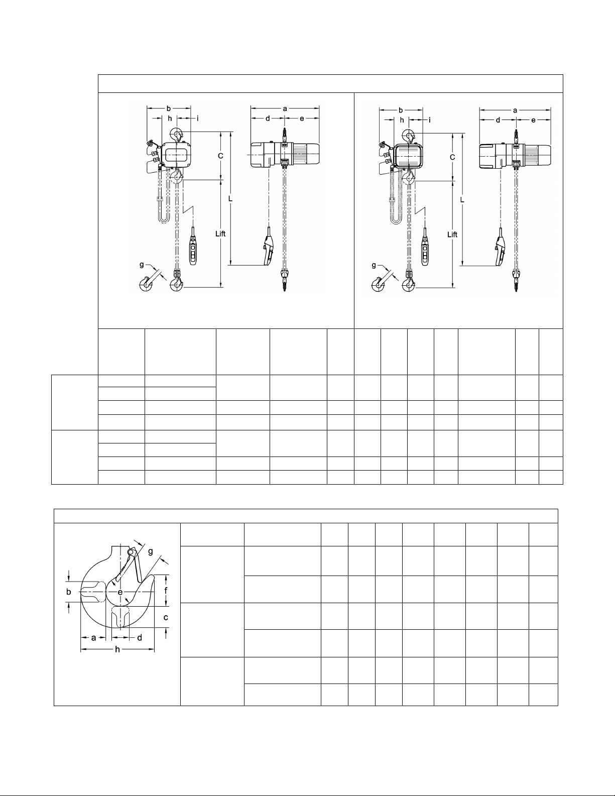
2.2 Dimensions
Hook C
1/4
NER2003L-FG
1/2 NER2005L-FG
1/4
NER2003LD-FG
1/2 NER2005LD-FG
1
NER2010LD-FG
16.9
21.3
24.1
14.8
12.4
11.7
1.2
1.5
5.1
4.6
Table 2-3 Hook Dimensions
(in)
Epoxy Painted
Table 2-2 Hoist Dimensions
Figure 2-1 Single Speed Hoist Dimensions
Capacity
(Tons)
Product Code
Headroom
C
(in)
Headroom
w/Stainless
(in)
Figure 2-2 Dual Speed Hoist Dimensions
a
(in) b (in) d (in) e (in) g (in)
g
w/Stainless
Hook
(in)
h
(in) i (in)
Single
Speed
Dual
Speed
T = Top Hook
B = Bottom Hook
1 NER2010L-FG
2 NER2020L-FG
2 NER2020LD-FG 22.6 23.4 27.9 16.8 14.6 13.3 1.6 1.7 6.3 5.4
Capacity Code
003L, 005L,
003LD, 005LD
010L, 010LD
020L, 020LD
14.6 17.7 20.2 13.7 9.5 10.6 1.1 1.2 4.4 4.2
g
(in)
5.1 4.6
h
16.9 21.2 23.2 14.8 11.4 11.7 1.2 1.5
22.6 23.4 25.4 16.8 12.1 13.3 1.6 1.7 6.3 5.4
14.6 17.7 22.4 13.7 11.8 10.6 1.1 1.2 4.4 4.2
a
b
c
Hook
Stainless Bottom
Epoxy Painted
Top & Bottom
Stainless Bottom
Epoxy Painted
Top & Bottom
Stainless Bottom 2.2 1.4 1.9 1.4 2.4 2.5 1.7 6.3
Top & Bottom
(in)
(in)
(in)
1.5 0.9 1.2 0.9 1.7 1.8 1.2 4.3
1.1 0.7 0.9 0.7 1.4 1.5 1.1 3.7
1.9 1.1 1.6 1.1 2.0 2.2 1.5 5.4
1.5 0.9 1.2 0.9 1.7 1.8 1.2 4.3
2.0 1.3 1.7 1.3 2.1 2.2 1.5 5.7
d
(in)
e
(in)
f
(in)
7
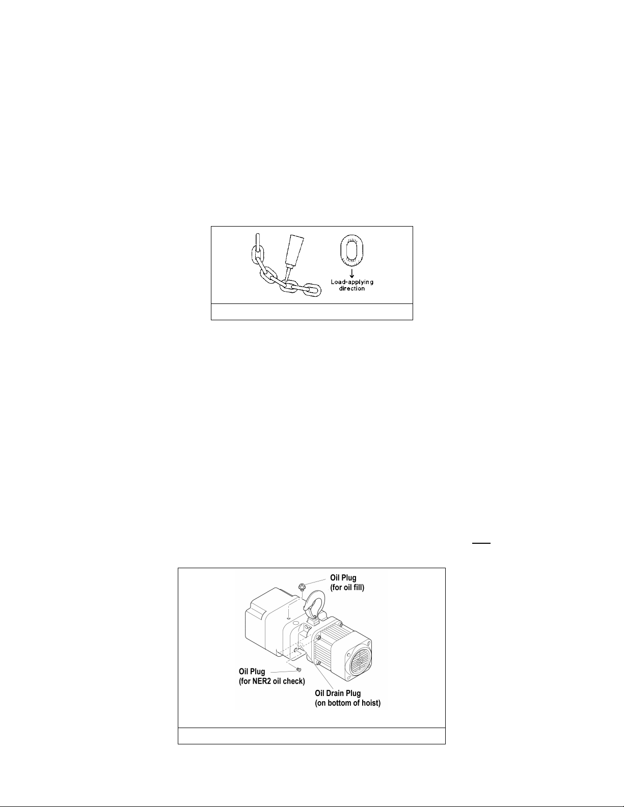
6.2 Lubrication – Load Chain, Hooks, and Suspension
6.2.1 Load Chain
• For longer life, the load chain should be lubricated.
• The load chain lubrication should be accomplished after cleaning the load chain with an acid
free cleaning solution.
• Apply only Harrington Hoist, Inc. food grade lubricant (Part No. 2AFG003S1951) to the bearing
surfaces of the load chain links as indicated by the shaded areas in Figure 6-2. Also apply the
lubricant to the areas of the load chain (shaded areas in Figure 6-2) that contact the load
sheave. Ensure that the lubricant is applied to the contact areas in the load sheave pockets.
Figure 6-2 Chain Grease Application
• The load chain should be lubricated every 3 months (more frequently for heavier usage or
severe conditions).
6.2.2 Hooks and Suspension Components
• Hooks – Bearings should be cleaned and lubricated at least once per year for normal usage.
Use only Nevastane HT/AW 2 White Drum food grade lubricating grease. Clean and lubricate
more frequently for heavier usage or severe conditions.
• Suspension Pins – Lubricate at least twice per year for normal usage; more frequently for
heavier usage or severe conditions.
6.3 Lubrication - Gearbox
6.3.2 DETERMINING OIL LIFE - Refer to Section 6.1.3 in the ER2OM when estimating gear oil life
based on operations.
6.3.3 NER2 OIL LEVEL – The oil level is checked by removing the oil plug on the side of the hoist as
shown in Figure 6-3 for NER2 hoists. The oil level should be just below the hole when the hoist is
level.
NER2 Hoists
Figure 6-3 Oil Plug Locations
8
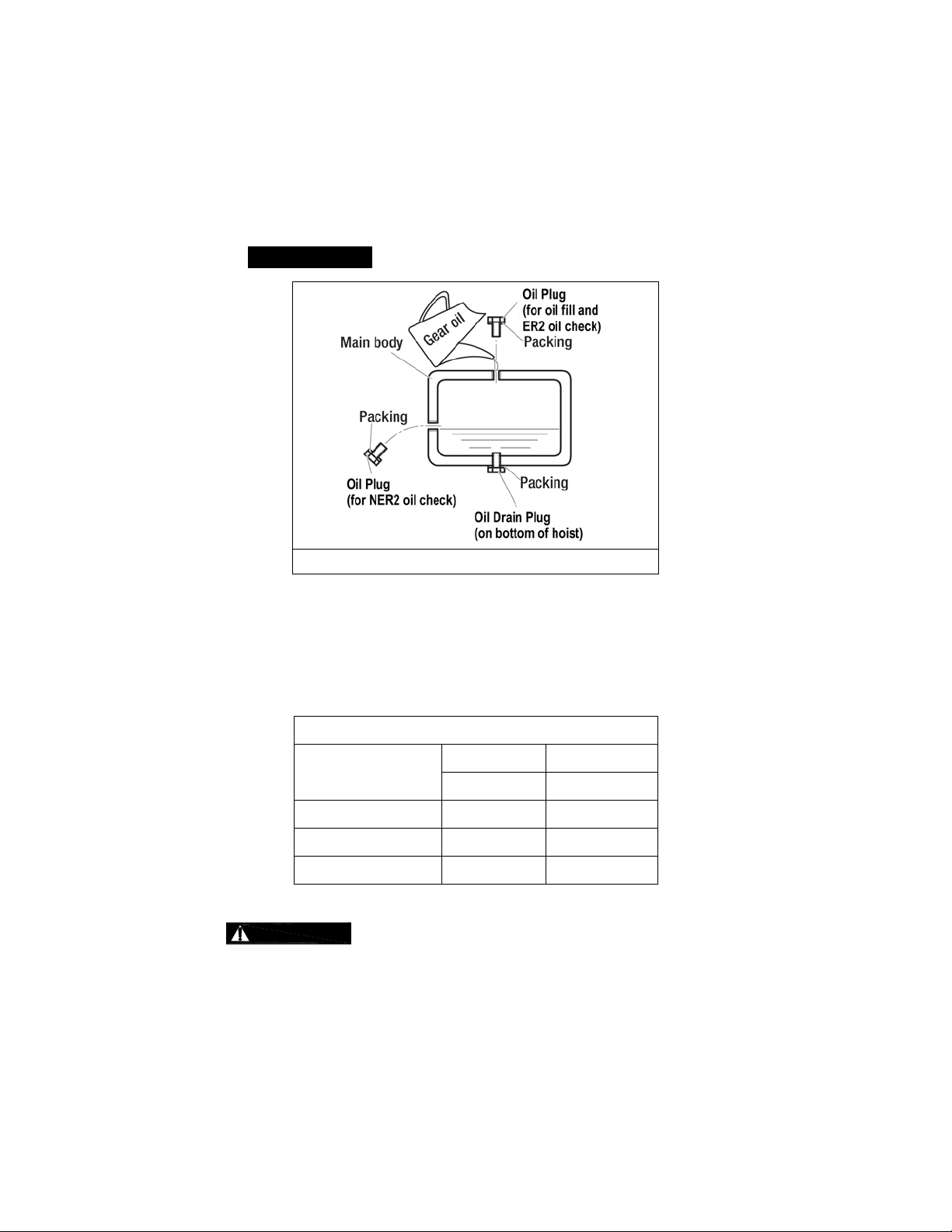
Figure 6-4
6.3.5 REPLACING OIL – Change gear oil at least once every 5 years. The oil should be
changed more frequently depending on the hoist's usage and operating environment. Refer to
Section 6.1.3. Follow the procedure below for replacing the gearbox oil for your hoist:
• To drain the current oil from the hoist remove “Oil Plug” on top of the hoist and the “Oil
Drain plug” on the bottom of the hoist. Allow the old oil to drain completely. Refer to
Figure 6-4 for oil plug locations.
•
Dispose of the used oil in accordance with local reg ulatio ns .
Oil Filling Diagram
• Ensure that the oil plugs for the oil level check holes and the drain hole are reinstalled
and secured into the hoist body.
• Refill the gear case with the correct quantity and type of new oil or until the oil level is
within the range shown in Table 6-6. Refer to Figure 6-4.
Table 6-6 Amount of Gear Oil
Capacity Code
003L/005L 0.57 0.54
010L 0.66 0.62
020L 1.37 1.30
may prevent the fr iction clu tch fr om working proper ly and m ay affect the a bility of the hoist to
hold the load. Onl y lu bricants with NSF H1 compliance m ay be used in f ood grade hoists.
Refer to the following for the correct type of gearbox oil:
NER Gear Oil:
Harrington standard: Ne vas tane SL 320 (Total Lubricants)
Using an incorrect type/grade of gearb ox oil or the wrong quantit y of oil
Quarts Liters
NER2 NER2
9

6.5 Load Chain
6.5.2 After chaining a unit, be s ure to clean any exp osed portions of bottom yoke bolts that have been
treated with thread locking compound. Conduct a thorough inspection of these bolts after
torquing to ensure there is no ex cess thread lock ing compound on t he expos ed portions. Failure
to do so could affect the hoist’s compliance with the application’s food grade requirements.
10

III MR2 Mot orized Trolley
Section Page Number
1.0 Important Information and Warnings………………...……………………………………….....….MR2OM
1.1 Terms and Summary
1.2 Warning Tag and Labels
2.0 Technical Information…………… ……………………………………….………….…………………..….13
2.1 Specifications
2.2 Dimensions
3.0 Pre-operational Procedures..……………………………………………………………................MR2OM
3.1 Assembly and Adjustment
3.2 Mounting Location
3.3 Installation of Trolley onto Beam
3.4 Electrical Connections
3.5 VFD Setup (Dual Speed Only)
3.6 Pre-operational Checks and Trial Operation
4.0 Operation………………………………………………………………………………………………MR2OM
4.1 Introduction
4.2 Shall’s and Shall Not’s for Operation
4.3 Trolley and Hoist Controls
5.0 Inspection………………………………………………………………………..…………………….MR2OM
5.1 General
5.2 Inspection Classification
5.3 Frequent Inspection
5.4 Periodic Inspection
5.5 Occasionally Used Trolleys
5.6 Inspection Records
5.7 Inspection Methods and Criteria
11

Section Page Number
6.0 Maintenance & Handling……………………………………………………………………………..MR2OM
6.1 Count/Hour Meter (Dual Speed Only)
6.2 Lubrication……………………………………………………..………………..14 and MR2OM
6.3 Brake
6.4 Storage
6.5 Outdoor Installation
6.6 Operational Environment
7.0 Troubleshooting……………………………………………………..………………………………..MR2OM
8.0 Warranty……………………………………………………………...………………………………. MR2OM
9.0 Parts List……………………………………………………………………………………………………...43
12
2.0 Specifications
Temperature Range:
-4° to +104°F (-20° to +40°C)
Humidity:
85% or less (no condensation)
hoist)
Enclosure Rating:
Trolley Meets IP55, Pendant Meets IP 65
Available
Dual Speed – 27/13% ED with 78/162 starts per hour
Trolley Duty Rating:
ISO M4/5; ASME H4
Current Draw
(amps)
208V or
230V
7.03 to 12.00
6.03 to 12.00
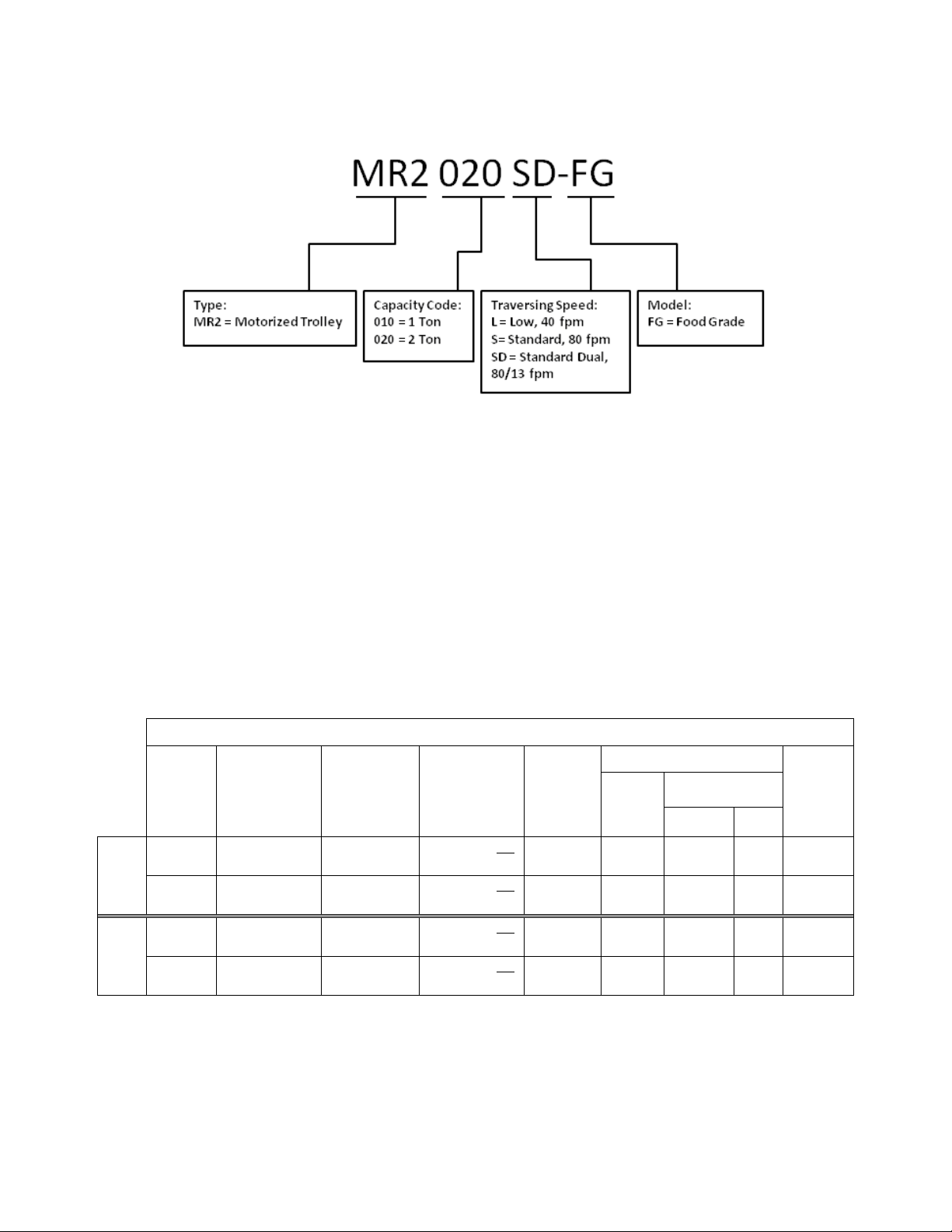
2.1.1 Product Code for MR2 Trolley Alone:
2.1.2 Operating Conditions and Environment
Noise Level: 85 dB or less (A scale: measured 1 meter away from the electric chain
Supply Voltage: Standard 208-230/460V-3-60, Optional 575V-3-60, Special Voltages
Intermittent Duty Rating:
Single Speed – 40% ED 240 starts per hour
Single
Dual
Capacity
(Ton)
1 MR2010L/S-FG 2.28 to 5.00
Speed
2 MR2020L/S-FG 3.23 to 6.02
1 MR2010SD-FG 2.28 to 5.00
Speed
2 MR2020SD-FG 3.23 to 6.02
Product Code
Beam Flange
Table 2-1 Trolley Specifications
Standard
Range
(in)
Optional Beam
Flange Range
(in)
5.01 to 6.02 OR
6.03 to 12.00
6.03 to 7.02 OR
5.01 to 6.02 OR
6.03 to 7.02 OR
7.03 to 12.00
(Hp)
Motor***
460V
Min.
Allowable
Radius
for Curve
(in)
31.5* 0.54 3.0 1.5 68
31.5** 0.54 3.0 1.5 84
31.5 0.54 3.0 1.5 75
31.5 0.54 3.0 1.5 93
Output
Approx.
Net
Weight
(lbs)
13
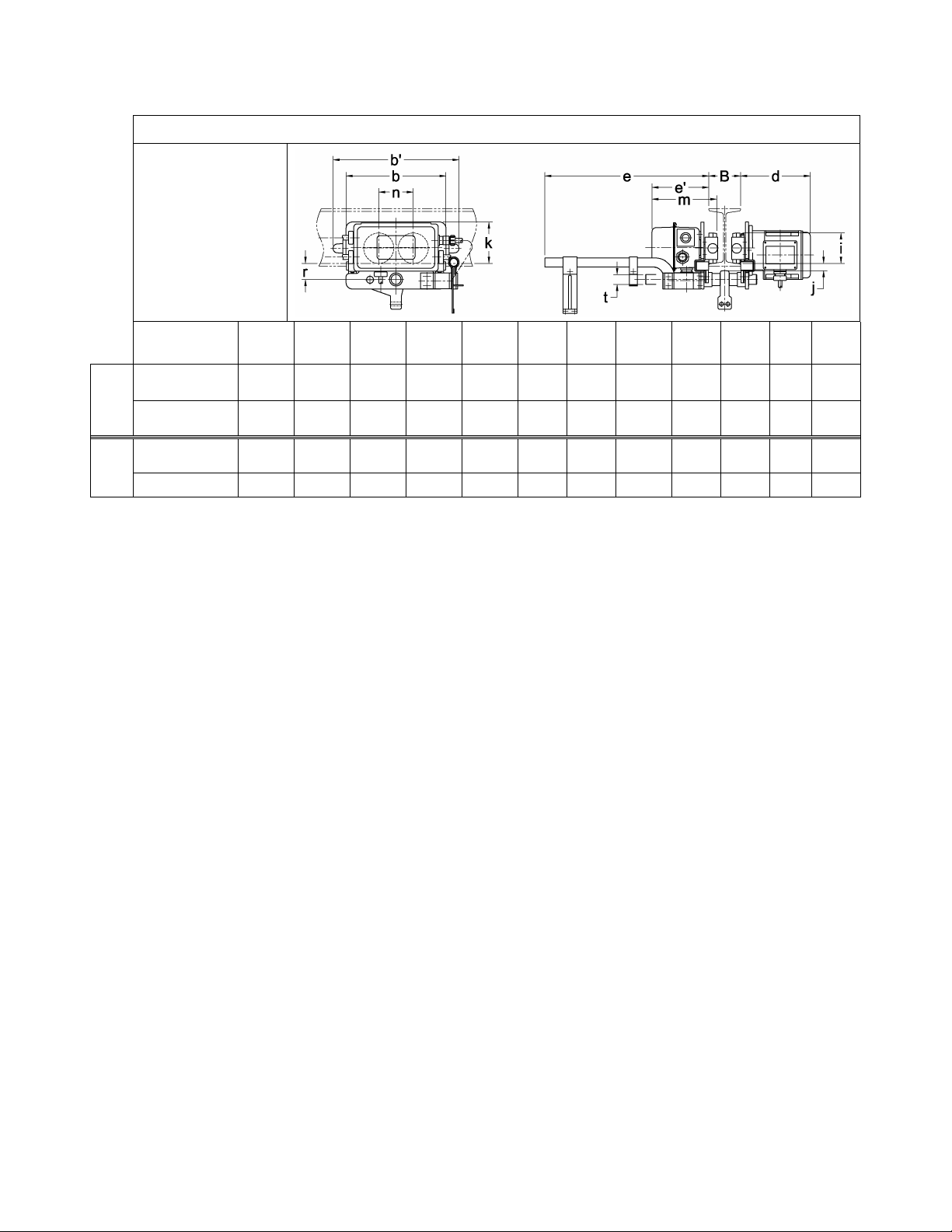
2.2 Dimensions
Table 2-2 Trolley Dimensions
For NER2003L-FG to
NER2020L-FG
Product
Code
MR2010L/S-FG 12.4 15.6 8.7 20.3 7.1 3.74 0.9 5.1 8.1 4.3 2.0 1.22
Single
Speed
MR2020L/S-FG 12.8 16.4 8.9 20.5 7.2 4.33 1.1 4.9 8.4 4.7 2.4 1.42
MR2010SD-FG 12.4 15.6 8.7 20.3 7.1 3.74 0.9 5.1 8.1 4.3 2.0 1.22
Dual
Speed
MR2020SD-FG 12.8 16.4 8.9 20.5 7.2 4.33 1.1 4.9 8.4 4.7 2.4 1.42
6.2 Lubrication
6.1.1 Lubricate the following trolley components with only Nevastane HT/AW 2 White Drum food grade
lubricating grease.
6.1.2 Track Wheel Gear – Clean and re-grease the Track Wheel gears and motor output pinion every
three months (more frequently for heavier usage or severe conditions). Do not use an excessive
amount of grease and avoid getting any grease on the running surfaces of the Track Wheels or
the beam.
6.1.3 Gear Box – The reduction gearing in the motor should be cleaned and lubricated at least once
per year for normal usage. Clean and lubricate the reduction gear assembly more frequently for
heavier usage or severe conditions. Gain access to the gears by removing the four bolts that
mount the motor assembly to the trolley Side Plate. Make sure to properly orient and reuse the
neoprene gasket between the motor and Side Plate.
b b' d e e' i j k m n r t
6.1.4 Suspension Pins, Bolts and Shafts – Grease at least twice per year for normal usage (more
frequently for heavier usage or severe conditions).
14

IV TS2 Manual Trolley
Section Page Number
1.0 Important Informa t ion and Warnings………………….…………………………………………. TS2OM
1.1 Terms and Summary
1.2 Warning Tags and Labels
2.0 Technical Information …………………………………………….………………….……..........……. 17
2.1 Specifications
2.2 Dimensions
2.3 Optional Equipment
3.0 Pre-operational Procedures…………………………………………………………………….... TS2OM
3.1 Manual Hoist Adjustment for Trolley
3.2 Electric Hoist Adjustment for Trolley
3.3 Air Power Hoist Adjustment for Trolley
3.4 Trolley Assembly
3.5 Mounting Location
3.6 Installation of Trolley onto Beam
3.7 Electrical/Air Connections
3.8 Pre-operational Checks and Trial Operation
4.0 Operation………………………………………………………………………………………...…. TS2OM
4.1 Introduction
4.2 Shall’s and Shall Not’s for Operation
4.3 Trolley Controls
5.0 Inspection………………………………………………………………………………………….. TS2OM
5.1 General
5.2 Inspection Classification
5.3 Frequent Inspection
15

Section Page Number
5.4 Periodic Inspection
5.5 Occasionally Used Trolleys
5.6 Inspection Records
5.7 Inspection Methods and Criteria
6.0 Maintenance & Handling………………………………………………………………………….. TS2OM
6.1 Lubrication……………………………………………………….……………….19 and TS2OM
6.2 Storage
6.3 Outdoor Installation
7.0 Warranty…………………………………………………………………………………………..…TS2OM
8.0 Parts List…………………………………………………………………………………………………... 59
8.1 TS2 Push Trolley Parts – 1/4 to 2 Ton
8.2 TS2 Geared Trolley Parts – 1/4 to 2 Ton
16
2.1 Specifications
Temperature Range:
-4° to +104°F (-20° to +40°C)
Humidity:
85% or less
Min.
(in)
Min.
(in)
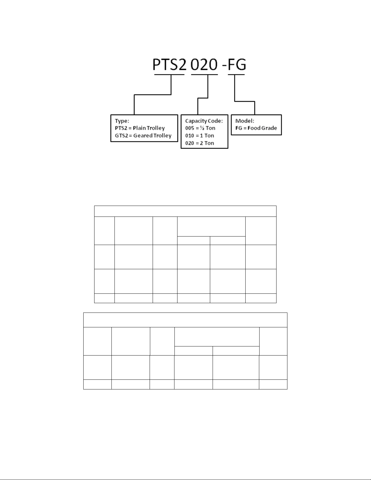
Product Code for TS2 Trolley Alone:
Operating Conditions and Environment
Table 2-1 PTS2 Trolley Specifications
Cap.
(Tons)
Product Code
1/2 PTS2005-FG 43.3 2.28 to 4.00
1 PTS2010-FG 51.2 2.28 t o 5.00
2 PTS2020-FG 59.1 3.23 t o 6.02 6.03 to 12.00 31
Radius
for
Curve
Flange Width Adjustability
B
(in)
Standard Option
4.01 to 8.00
or
8.01 to 12.00
5.01 to 8.00
or
8.01 to 12.00
Approx. Net
Weight
(lbs)
10
18
Table 2-2 GTS2 Trolley Specifications
Cap.
(Tons)
1 GTS2010-FG 51.2 2.28 to 5.00
2 GTS2020-FG 59.1 3.23 to 6.02 6.03 to 12.00 42
Product Code
Radius
for
Curve
Flange Width Adjustability
B
(in)
Standard Option
5.01 to 8.00
or
8.01 to 12.00
Approx.
Net
Weight
(lbs)
27
17
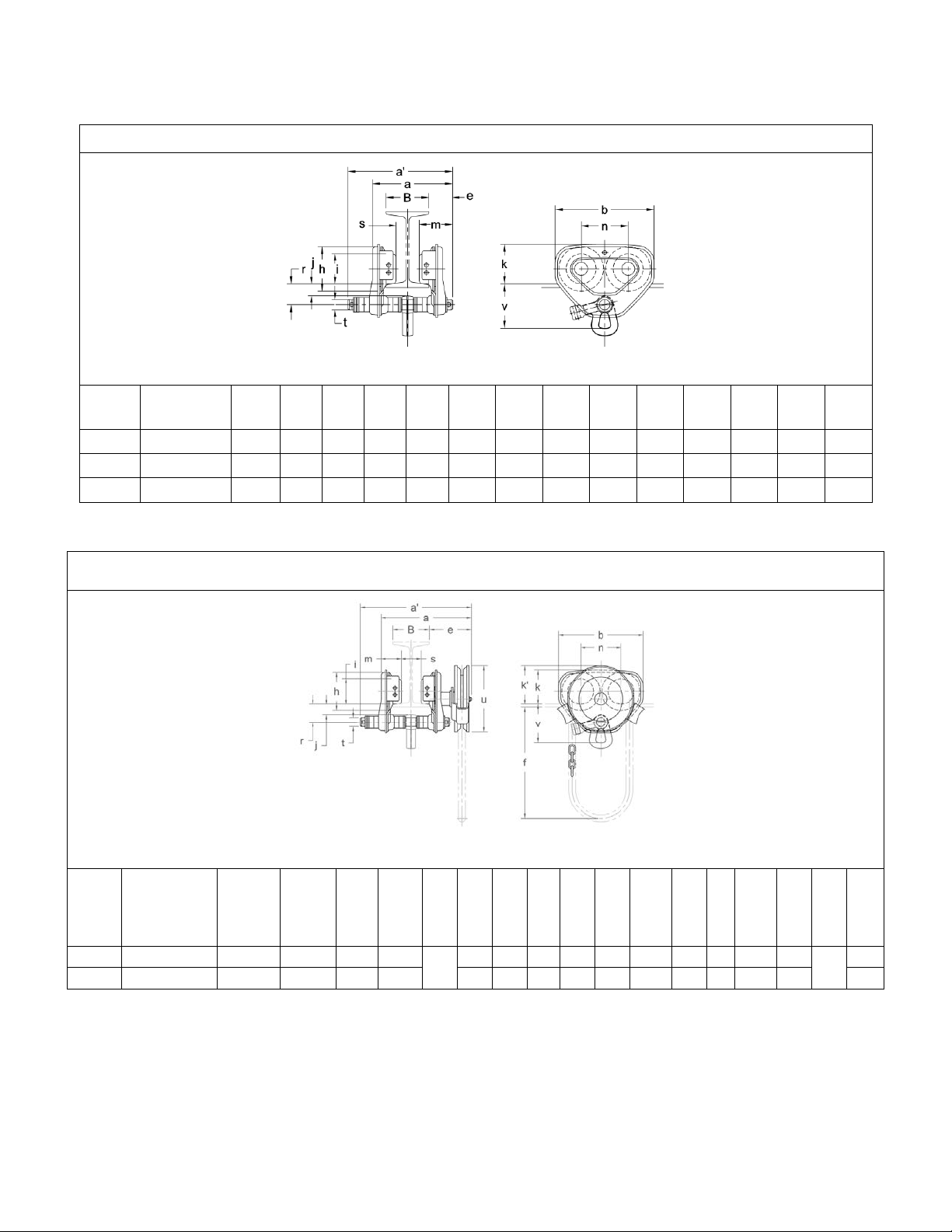
2.2 Dimensions
a
(in)
Table 2-3 PTS2 Trolley Dimensions
PTS2005 to PTS2020
Cap.
(Tons)
1/2 PTS2005-FG 6.8 8.0 7.2 1.8 3.2 2.36 0.7 3.0 2.7 3.3 1.5 B-1.8 0.87 3.7
1 PTS2010-FG 8.5 9.8 9.3 2.2 4.2 2.80 1.1 3.7 3.1 4.4 2.0 B-1.9 0.98 4.2
2 PTS2020-FG 10.4 11.8 11.0 2.7 5.0 3.35 1.3 4.4 3.8 5.2 2.4 B-2.3 1.26 5.1
Product
Code
max
a'
(in) b (in) e (ft) h (in) i (in) j (in) k (in) m (in) n (in) r (in) s (in) t (in) v (in)
Table 2-4 GTS2 Trolley Dimensions
GTS2010 to GTS2020
Cap.
(Tons)
1/2-1 GTS2010-FG 10.8 13.6 9.3 6.0
Product Code
2 GTS2020-FG 13.7 15.2 11.0 6.1 5.0 3.35 1.3 4.4 4.3 2.8 5.2 2.4 B-1.9 1.26 5.1
a
max*
(in)
a’
max
(in)
b
(in) e (in) f (ft.) h (in)
4.2 2.80 1.1 3.7 4.2 2.2 4.4 2.0 B-1.8 0.98
10.5
i
(in) j (in) k (in)
k'
(in) m (in) n (in) r (in) s (in) t (in) u (in) v (in)
7.2
18
4.2

6.1 Lubrication
6.1.1 Lubricate the following trolley components with only Nevastane HT/AW 2 White Drum food grade
lubricating grease.
6.1.2 Track Wheel Gear – Clean and re-grease the Track Wheel gears and Hand Wheel output pinion every
three months (more frequently for heavier use). Do not use an excessive amount of grease and avoid
getting any grease on the running surfaces of the Track Wheels or the beam.
6.1.3 Trolley Wheel Bearings do not need to be lubricated and must be replaced if worn or damaged.
6.1.4 Suspension Pins, Bolts, and Shafts – Grease at least twice per year for normal usage (more frequently
for heavier usage or severe conditions).
19

This Page Intentionally Left Blank
20
 Loading...