

Harrington ER2003H, ER2010L, ER2005S, ER2005L, ER2010S Owner's Manual
...
EFFECTIVE: February 19, 2009
Owner’s Manual
ELECTRIC
CHAIN HOIST
ER2 and NER2
SERIES
1/8 Ton through 5 Ton Capacity
Code, Lot and Serial Number
WARNING
This equipment should not be installed, operated, or
maintained by any person who has not read and understood
all the contents of this manual. Failure to read and comply
with the contents of this manual can result in serious bodily
injury or death, and/or property damage.

Table of Contents
Section Page Number
1.0 Important Information and Warnings ……………………………………………………………………… 4
1.1 Terms and Summary
1.2 Warning Tags and Labels
2.0 Technical Information…………………………………………………………………………….…………. 8
2.1 Specifications
2.2 Dimensions
3.0 Preoperational Procedures ……………………………………………………………………………… 13
3.1 Gearbox
3.2 Chain
3.3 Mounting Location
3.4 Mounting the Hoist
3.5 Electrical Connections
3.6 VFD Setup (Dual Speed Only)
3.7 Preoperational Checks and Trial Operation
4.0 Operation …………………………………………………………………………………………………... 25
4.1 Introduction
4.2 Shall’s and Shall Not’s for Operation
4.3 Hoist Controls
5.0 Inspection ………………………………………………………………………………………………….. 29
5.1 General
5.2 Inspection Classification
5.3 Frequent Inspection
5.4 Periodic Inspection
5.5 Occasionally Used Hoists
5.6 Inspection Records
5.7 Inspection Methods and Criteria
2

Section Page Number
6.0 Maintenance & Handling …………………………………………………………………………………. 39
6.1 Count/Hour Meter
6.2 Lubrication – Load Chain, Hooks and Suspension
6.3 Lubrication – Gearbox
6.4 Motor Brake
6.5 Load Chain
6.6 Friction Clutch and Mechanical Load Brake with Friction Clutch
6.7 Storage
6.8 Outdoor Installation
6.9 Operational Environment
7.0 Troubleshooting …………………………………………………………………………………………… 47
8.0 Warranty …………………………………………………………………………………………………… 50
9.0 Parts List …………………………………………………………………………………………………… 51
3

1.0 Important Information and Warnings
1.1 Terms and Summary
This manual provides important information for personn el involved with the insta llation, operation an d maintenance
of this product. Although you may be familiar with this or similar equipment, it is strongly recommended that you read
this manual before installing, operating or maintaining th e product.
Danger, Warning, Caution and Notice
Throughout this manual there are steps and proce dures that can present ha zardous situatio ns. The following signal
words are used to identify the degree or level of hazard seri ousness.
DANGER
WARNING
CAUTION
NOTICE
Danger indicates an imminently hazardou s situation which, if not avo ided, will result in death or
serious injury, and property damage.
Warning indicates an imminently hazardous situatio n which, if not avoided, could result in death or
serious injury, and property damage.
Caution indicates a potentially hazardous situation whi ch, if not avoided, may re sult minor or
moderate injury or property damage.
Notice is used to notify people of installation, operation, or maintenanc e information whi ch is
important but not directly hazard-related.
CAUTION
These general instructions deal with the no rmal installatio n, operation, and maint enance situation s encountered with
the equipment described herein. The inst ructions sh ould not be interp reted to anticipate eve ry possible co ntingency
or to anticipate the final system, crane, or configuratio n that uses this e quipment. For syst ems using the equipment
covered by this manual, the supplier and o wner of the syst em are responsible for the system’s compliance with all
applicable industry standards, a nd with all app licable federal, st ate and local regul ations/code s.
This manual includes instructions an d parts information for a v ariety of hoi st types. Therefore, all i nstructions an d
parts information may not apply to any one type or size of specific hoist. Disregard those portions of the instructions
that do not apply.
Record your hoist’s Code, Lot and Serial Numb er (see section 1 0) on the front cover of thi s manual for identifi cation
and future reference to avoid referring to the wrong m anual for inform ation or instru ctions on instal lation, operation,
inspection, maintenance, or parts.
Use only Harrington authorized replacement pa rts in the se rvice and mainte nance of this hoi st.
4

WARNING
Equipment described herein is not designed for and MUST NOT
people, or for lifting or supporting load s over people.
Equipment described herein should not be used i n conjunction with other equi pment unless necessary and/ or
required safety devices applicable to the system, crane, or appli cation are instal led by the syste m designe r, system
manufacturer, crane manufacturer, installer, or user.
Modifications to upgrade, rerate, or otherwise alter this equipm ent shall be auth orized only by the ori ginal equipment
manufacturer.
Equipment described herein may be used in the desi gn and manufactu re of cranes or mon orails. Additional
equipment or devices may be required for the crane and monorail to comply with applicabl e crane desi gn and
safety standards. The crane designer, crane manufacturer, or user is responsible to furnish these additional items
for compliance. Refer to ANSI/ASME B30.17, “Safety Standard for Top-Running Single Girder Cranes”;
ANSI/ASME B30.2 “Safety Standard for Top-Running Double-Girder Cranes”; and ANSI/ASME B30.11 “S afety
Standard for Underhung Cranes and Mon orails”.
If a below-the-hook lifting device or sling is used with a hoist, refer to ANSI/ASME B30.9, “Safety Standard for
Slings” or ANSI/ASME B30.20, “Safety Standard for Below-the-Hook Lifting Devices”.
be used for lifting, supporting, or transporting
Hoists and cranes, used to handle hot molten material m ay require additional e quipment or device s. Refer to ANS I
Z241.2, “Safety Requirements for Melting and P ouring of Metal s in the Metal Ca sting Indust ry”.
Electrical equipment described herein is design ed and built in co mpliance with Harri ngton's interpretation of
ANSI/NFPA 70, “National Electrical Code”. The system designer, system manufacturer, crane designer, crane
manufacturer, installer, or user is resp onsible to a ssure that the i nstallation a nd associated wi ring of these electrical
components is in compliance with ANSI/NFPA 70, and all applicable Federal, State and Local Codes.
Failure to read and comply with any one of the limitation s noted herein can result in seriou s bodily injury or death,
and/or property damage.
5

DANGER
HAZARDOUS VOLTAGES ARE PRESENT IN THE CONTROL BOX, OTHER ELECTRICAL COMPONENTS,
AND CONNECTIONS BETWEEN THESE COMPONENTS.
Before performing ANY mechanical or electrical mainten ance on the equipme nt, de-energize (disconn ect) the main
switch supplying power to the equipment; as well as lock and t ag the main switch in the d e-energized positio n.
Refer to ANSI Z244.1, “Personnel Protection – Locko ut/Tagout of Energy Sources”.
Dual speed units incorporate a VFD as well as a Capacitor. Therefor e, DO NOT perform ANY mech anical or
electrical maintenance within 5 minutes of po wering down to allow time for the ca pacitor inside the VF D to
discharge. DO NOT perform any voltage or insulation resi stance tests with a meg ohmmeter when the VFD
is connected to the electrical circuit.
Only trained and competent personnel should i nspect and repair th is equipment.
NOTICE
It is the responsibility of the owner/user to install, inspect, test, ma intain, and operate a hoist in accordance with
ANSI/ASME B30.16, “Safety Standard for Overhead Hoists”, OSHA Regulations and ANSI/NFPA 70, National
Electric Code. If the hoist is installed as part of a total lifti ng system, such a s an overhead crane or monorail, it is
also the responsibility of the owner/user to comply with the applicable ANSI/ASME B30 volume that addresses that
type of equipment.
It is the responsibility of the owner/user to have all personne l that will install, in spect, test, maint ain, and operate a
hoist read the contents of this manual and appli cable portions of ANSI/ ASME B30.16, “Safety Standa rd for
Overhead Hoists”, OSHA Regulations and ANSI/NFPA 70, “National Electric Code ”. If the hoist is installed a s part
of a total lifting system, such as an overhead crane, the applicable ANSI/ASME B30 volume that addresses that
type of equipment must also be read by all perso nnel.
If the hoist owner/user requires additional information, o r if any information in the m anual is not clear, co ntact
Harrington or the distributor of the hoist. Do not inst all, inspect, test, maintain, or operate this hoist unless this
information is fully understood.
A regular schedule of inspection of the hoist in accordance with the requirements of ANSI/ASME B30.16 should be
established and records maintained.
6
1.2 Warning Tags and Labels
The warning tag illustrated below in Figure 1-1 is supplie d with each hoist ship ped from the factory. If the tag i s
not attached to your hoist’s pendant cord, order a tag from your deal er and install it. Read and obe y all
warnings attached to this hoist. Tag is not sh own actual si ze.
front back
Figure 1-1 Warning Tag Attached to Hoist
7
2.0 Technical Information
2.1 Specifications
Note: This Owners Manual is for the Enhanced Features Model ER and NER. This
Enhanced Features Model is referred to as the ER2 and NER2 in this Owners Manual.
Pendants are shown with optional Emergency Stop button.
2.1.1 Product Code
2.1.2 ER2 and NER2 Models - Harrington E R2 series hoist s are available in t wo versions, the ER2 and
NER2. These two versions differ with the presence of a me chanical load bra ke as standard equi pment.
The ER2 has a mechanical load brake/friction clutch combination while the NER2 has a friction clut ch
mechanism that provides over winding p rotection. Refe r to Figure 2-1 for the visual differences
between the ER2 and NER2.
Figure 2-1 Identifying ER2 verses NER2 Models
8

2.1.3 Operating Conditions and Environment
Temperature range: -4° to +104°F (-20° to +40°C)
Humidity: 85% or less
Noise Level: 85 dB or less (A scale: measured 1 meter away from electric chai n hoist
Enclosure Rating: Hoist Meets IP55, Pendant Meets IP65
Supply Voltage: Single Speed Standard: Reconnectable 208/230 & 460V-3-60
Single Speed Optional: 575V-3-60 or Special Volta ges/Frequenci es Available
Dual Speed Standard: 208/230V-3-6 0 or 460V-3-6 0
Dual Speed Optional: 575V-3-60 or Voltages/Frequencie s Voltages Available
Single Speed Dual Speed
Hoist Duty Rating: ISO M4/M5; ASME H4
Intermittent Duty Rating: 60% ED
360 starts per hour
40/20% ED
120/240 starts per hour
Short Time Duty Rating: 60 min. 30/10 min.
9

Capacity
SINGLE SPEED
DUAL SPEED
Table 2-1 Hoist Specifications
Motor
Product
Code
(Ton)
1/8 (N)ER2001H 55 0.75 3.4 1.7 4.3 x 1 6 60 62 0.28
1/4 (N)ER2003S 36 0.75 3.4 1.7 4.3 x 1 6 60 62 0.28
1/4 (N)ER2003H 53 1.2
1/2 (N)ER2005L 15 0.75 3.4 1.7 6.0 x 1 5 71 79 0.54
1/2 (N)ER2005S 29 1.2 4.8 2.5 6.0 x 1 5 79 82 0.54
1 (N)ER2010L 14 1.2
1 (N)ER2010S 28 2.4 8.6 4.2 7.7 x 1 5 119 119 0.89
1 1/2 (N)ER2015S 18 2.4 8.6 4.2 10.2 x 1 5 159 170 1.6
2 (N)ER2020C 7 1.2
2 (N)ER2020L 14 2.4 8.6 4.2 10.2 x 1 5 161 174 1.6
2 (N)ER2020S 28 4.7 16.4 7.9 10.2 x 1 5 201 198 1.6
2 1/2 (N)ER2025S 22 4.7
3 (N)ER2030L TBD TBD
3 (N)ER2030C 17 4.7 16.4 7.9 10.2 x2 5 234 234 3.2
5 (N)ER2050L 11 4.7 16.4 7.9 11.2 x 2 5 289 284 3.8
1/8 (N)ER2001HD 55/9 0.75 3.6 1.8 4.3 x 1 6 60 64 0.28
1/4 (N)ER2003SD 36/6 0.75 3.6 1.8 4.3 x 1 6 60 64 0.28
1/4 (N)ER2003HD 53/9 1.2
1/2 (N)ER2005LD 15/2.5 0.75 3.6 1.8 6.0 x 1 5 68 79 0.54
1/2 (N)ER2005SD 29/5 1.2 5.1 2.7 6.0 x 1 5 77 82 0.54
1 (N)ER2010LD 14/2.5 1.2
1 (N)ER2010SD 28/4.5 2.4 9.1 4.5 7.7 x 1 5 115 117 0.89
1 1/2 (N)ER2015SD 18/3 2.4 9.1 4.5 10.2 x 1 5 159 172 1.6
2 (N)ER2020CD 7/1 1.2
2 (N)ER2020LD 14/2.5 2.4 9.1 4.5 10.2 x 1 5 161 174 1.6
2 (N)ER2020SD 28/4.5 4.7 17.3 8.3 10.2 x 1 5 196 203 1.6
2 1/2 (N)ER2025SD 22/3.5 4.7
3 (N)ER2030LD TBD TBD TBD TBD TBD TBD TBD TBD TBD
3 (N)ER2030CD 17/3 4.7 17.3 8.3 10.2 x 2 5 229 238 3.2
5 (N)ER2050LD 11/2 4.7
Lifting
Speed
(ft/min)
Output
(Hp)
Current Draw
(amps)
208V or
230V
4.8 2.5
4.8 2.5
4.8 2.5
16.4 7.9
TBD TBD
5.1 2.7
5.1 2.7
5.1 2.7
17.3 8.3
17.3 8.3
460V NER ER
Load
Chain
Wire
Diameter
(mm) x
Chain Fall
Lines
6.0 x 1 5
7.7 x 1 5
7.7 x 2 5
11.2 x 1 5
TBD
6.0 x 1 5
7.7 x 1 5
7.7 x 2 5
11.2 x 1 5
11.2 x 2 5
Net Weight
Load
Sheave
(lbs)
Pockets
79 82
104 110
130 134
227 225
TBD TBD TBD
77 82
99 108
123 132
218 231
280 293
Weight
for One
Addnl.
FT. of
Lift
(lbs)
0.54
0.89
1.8
1.9
TBD
0.54
0.89
1.8
1.9
3.8
10
2.2 Dimensions
Figure 2-2 Single Speed Hoist Dimensions
(See Table 2-3)
Figure 2-3 Dual Speed Hoist Dimensions
(See Table 2-3)
Table 2-2 Hook Dimension*
Capacity Code Hook a b c d e g
001H, 003S, 003H,
005L, 005S
001HCC, 003SCC
010L, 010S T & B 1.5 0.9 1.2 0.9 1.7 1.2
020C T & B
015S
020L, 020S T & B
025S
030L, 030C T & B
050L T & B 2.6 1.7 2.2 1.7 2.5 1.9
T & B 1.1 0.7 0.9 0.7 1.4 1.1
T
B 0.8 0.5 0.7 0.5 1.4 0.9
T 2.0 1.3 1.7 1.3 2.1 1.5
B 1.7 1.1 1.5 1.1 1.9 1.3
T 2.0 1.3 1.7 1.3 2.4 1.7
B 2.0 1.3 1.7 1.3 2.1 1.5
1.1 0.7 0.9 0.7 1.4 1.1
1.9 1.1 1.6 1.1 2.0 1.5
2.0 1.3 1.7 1.3 2.1 1.5
2.2 1.4 1.9 1.4 2.4 1.7
T = Top Hook
B = Bottom Hook
Units = inch
*Refer to Section 5.7 for inspection dimensi ons and lim its.
11

Minimum
Product
Code
Headroom
C
(in)
(N)ER2001H 13.8 8.2 18.8 22.2 12.6 13.6 8.6 12.0 10.2 10.2 1.1 3.9 3.7 4.6
(N)ER2003S 13.8 8.2 18.8 22.2 12.6 13.6 8.6 12.0 10.2 10.2 1.1 3.9 3.7 4.6
(N)ER2003H 14.6 8.2 20.1 23.3 13.7 13.7 9.5 12.8 10.6 10.6 1.1 4.5 4.2 4.2
(N)ER2005L 14.6 8.2 20.2 23.6 13.7 13.7 9.5 12.8 10.7 10.8 1.1 4.5 4.2 4.2
(N)ER2005S 14.6 8.2 20.1 23.3 13.7 13.7 9.5 12.8 10.6 10.6 1.1 4.5 4.2 4.2
(N)ER2010L 16.9 8.2 23.2 24.9 14.8 14.8 11.5 13.1 11.7 11.8 1.2 5.1 4.6 4.6
(N)ER2010S 16.9 8.2 23.5 25.2 14.8 14.8 11.5 13.1 12.1 12.1 1.2 5.1 4.6 4.6
(N)ER2015S 20.1 8.2 25.4 29.1 16.8 16.8 12.1 15.6 13.3 13.4 1.3 6.3 5.4 5.4
(N)ER2020C 27.8 8.2 23.2 24.9 14.8 14.8 11.5 13.1 11.7 11.8 1.5 7.0 2.7 2.7
SINGLE SPEED
(N)ER2020L 22.6 8.2 25.4 29.1 16.8 16.8 12.1 15.6 13.3 13.4 1.5 6.3 5.4 5.4
(N)ER2020S 23.2 8.2 27.7 30.8 16.8 16.8 13.7 16.8 14.0 14.0 1.5 6.3 5.4 5.4
(N)ER2025S 24.6 8.2 29.0 32.5 17.5 17.5 13.3 16.8 15.7 15.7 1.5 6.9 5.6 5.6
(N)ER2030L
(N)ER2030C 32.9 9.2 27.7 30.8 16.8 16.8 13.7 16.8 14.0 14.0 1.7 8.5 3.2 3.2
(N)ER2050L 35.8 9.2 29.0 32.5 17.5 17.5 13.3 16.8 15.7 15.7 1.9 9.1 3.4 3.3
(N)ER2001HD 13.8 8.2 21.1 22.2 13.6 10.9 12.0 10.2 10.2 1.1 3.9 4.6
(N)ER2003SD 13.8 8.2 21.1 22.2 13.6 10.9 12.0 10.2 10.2 1.1 3.9 4.6
(N)ER2003HD 14.6 8.2 22.4 23.3 13.7 11.8 12.8 10.6 10.6 1.1 4.5 4.2
(N)ER2005LD 14.6 8.2 22.5 23.6 13.7 11.8 12.8 10.7 10.8 1.1 4.5 4.2
(N)ER2005SD 14.6 8.2 22.4 23.3 13.7 11.8 12.8 10.6 10.6 1.1 4.5 4.2
(N)ER2010LD 16.9 8.2 24.2 24.9 14.8 12.4 13.1 11.7 11.8 1.2 5.1 4.7
(N)ER2010SD 16.9 8.2 24.5 25.2 14.8 12.4 13.1 12.1 12.1 1.2 5.1 4.7
(N)ER2015SD 20.1 8.2 28.0 29.1 16.8 14.7 15.6 13.3 13.4 1.3 6.3 5.4
(N)ER2020CD 27.8 8.2 24.2 24.9 14.8 12.4 13.1 11.7 11.8 1.5 7.0 2.7
DUAL SPEED
(N)ER2020LD 22.6 8.2 28.0 29.1 16.8 14.6 15.6 13.3 13.4 1.5 6.3 5.4
(N)ER2020SD 23.2 8.2 30.2 30.8 16.8 16.2 16.8 14.0 14.0 1.5 6.3 5.4
(N)ER2025SD 24.6 8.2 31.5 32.5 17.5 15.8 16.8 15.7 15.7 1.5 6.9 5.6
(N)ER2030LD TBD TBD TBD TBD TBD TBD TBD TBD TBD TBD TBD TBD
(N)ER2030CD 32.9 9.2 30.2 30.8 16.8 16.2 16.8 14.0 14.0 1.7 8.5 3.2
(N)ER2050LD 35.8 9.2 31.5 32.5 17.5 15.8 16.8 15.7 15.7 1.9 9.1 3.4
TBD
L*
(ft)
NER ER NER ER NER ER NER ER NER ER
TBD TBD TBD TBD TBD TBD TBD TBD TBD TBD TBD TBD
TBD
Table 2-3 Hoist Specifications
a
(in)
b
(in)
d
(in)
e
(in)
g
(in) h (in)
i
(in)
*The "L" dimensions are based o n the standard lift of 10 feet.
12
3.0 Preoperational Procedures
3.1 Gearbox
3.1.1 The gearbox is filled with the correct amount of oil at the time of shipment. The oil level must be verified
prior to operation. The ER2 and NER2 hoists hav e different checki ng procedu res. Refer to Section 6.3
for specific checking procedures.
3.1.2 Refer to Section 6.3 when replacing the gear oil.
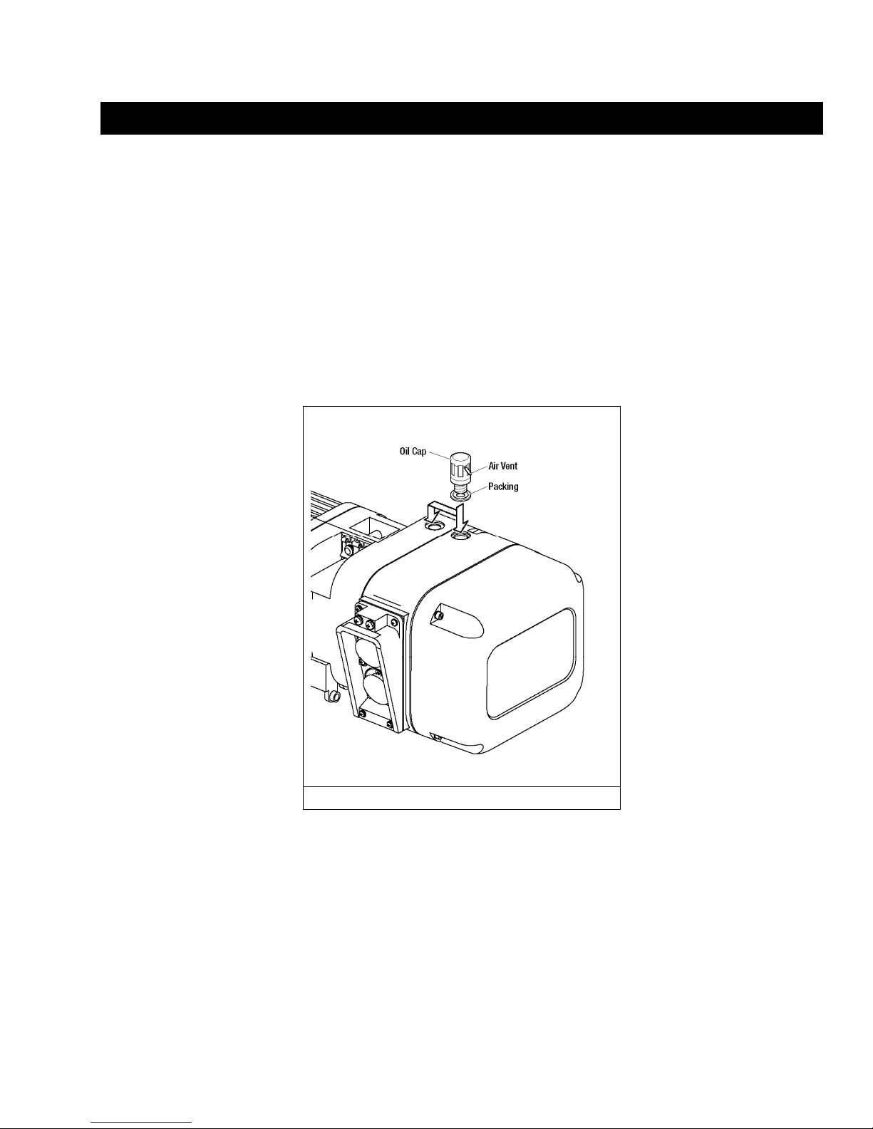
3.1.3 All ER2, mechanical load brake installed, hoist s are shipped with a separate air vent ed oil cap. This
vented oil cap must be installed prior to use . To install, remove an existing oi l cap and replac e with the
vented oil cap (refer to Figure 3-1).
3.1.4 There are two oil fill holes located in the top of the gear case on the ER2 hoist. For ER2 coupled to
MR2 trolley, there are some flange widths that make it necessary to relocate the oil cap assembly to the
other oil fill hole. This will prevent interference with trolley side plate. Refer to Figure 3-1.
Figure 3-1 Vented Oil Cap Installation
13
3.2 Chain
3.2.1 The quantity and location of the chain compon ents includi ng cushion rubbers, chain spring s, and striker
plates depend on the hoist model, capacity, and limits switches. Nev er operate the hoi st with incorrect,
missing, or damaged chain component s. Refer to the hoist's na meplate, Table 3-1, as well as Figures
3-2, 3-3. Ensure that all chain components are in the correct location and properly installed.
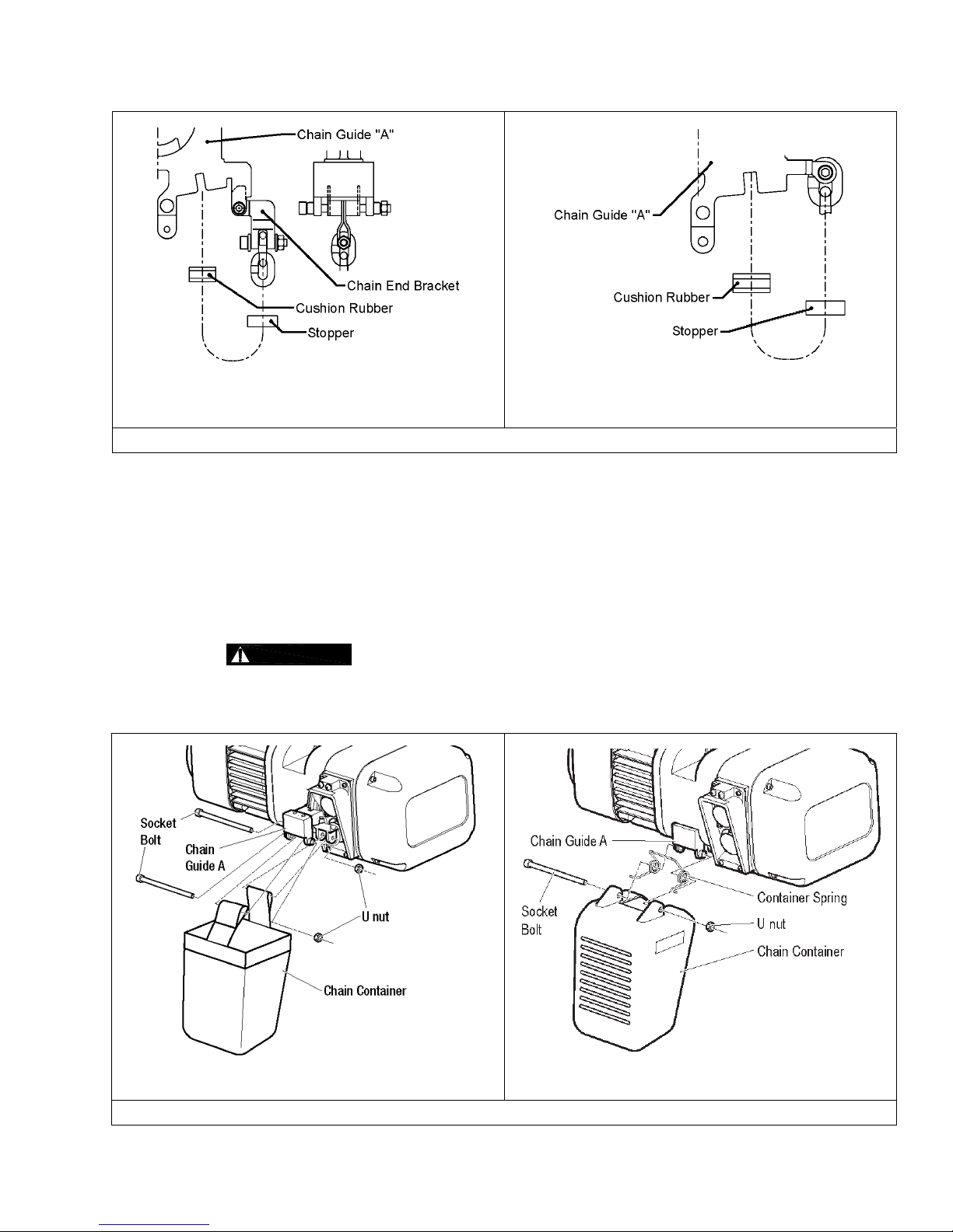
3.2.2 When the hoist is used without a chain contain er, the free end of the chain is atta ched to the hoist b ody
as shown in Figure 3-4. Connect the no load end of the chain to Chain Guide A with the En d
Suspender provided. For 5 ton hoist, connect the no load end of the chain dire ctly to Chain Gui de A if
Chain Guide A is notched to accept the chain. Ma ke sure the chai n remains free of twi sts and the
chain Stopper is installed on the co rrect link. Refer to Table 3-1 for proper placement of Stopper.
Figure 3-2 Chain Component Arrangement for Single Fall and Double Fall Hoists.
Table 3-1 Chain Stopper Placement
Capacity Code Without Chain Container With Chain Container
001H & 003S 21st link from the free end 3rd link from the free end
003H, 005L, 005S, 010L, 010S,
015S, 020C, 020L, 020S, 025S,
th
15
link from the free end 3rd link from the free end
030L, 030C, 050L
*Tightening torque for the Stoppe r Bolt: 10 N-m (7 lb-ft)
14
001H, 003S, 003H, 005L, 005S, 010L,
010S, 015S, 020L, 020S, 025S, 030C
020C, 050L
Figure 3-3 Attachment of Chain to Hoist Body – No Chain Conta iner
3.2.3 Optional Canvas or Plastic Chain Container - When the optional canvas ch ain container i s selected,
fully unfold and install it on the hoist body as sh own in Figure 3 -4. When installi ng the optional pla stic
chain container, pass the socket bolt through the holes in this order: the chain containe r, the bucket
spring, the chain guide A, the bucket spring, an d the chain cont ainer. Be sure to mount th e bucket
spring in correct direction as shown in Fig ure 3-4. The free end of the chain is not att ached to the hoist
body and the chain stopper is installed on the thi rd link from the free end . To place the chain i nto the
chain container, feed the free end of the chain i nto the container. Take care to avoid t wisting or
tangling the chain. NEVER put all the chain into the container at once. Lumped or twisted chain m ay
activate the down limit switch and stop the hoist d uring loweri ng.
3.2.4
CAUTION
Each chain container indicates the maximum lengt h of the load chain that can be
stored in the container. The amount of chain the container must hold i s equal to the lift on th e hoist.
DO NOT use a chain container with a storage capacity less than the lif t length on the hoi st. If all of the
chain cannot be stored in the container, the limit switch will not operate properly.
Canvas Chain Container
Figure 3-4 Attachment of Chain Container to Hoist Body
Plastic Chain Container
15
3.2.5 When using an optional steel chain container, refer to the assembly dra wing and instructi ons provided
with the container for correct assembly and attachment.
3.2.6
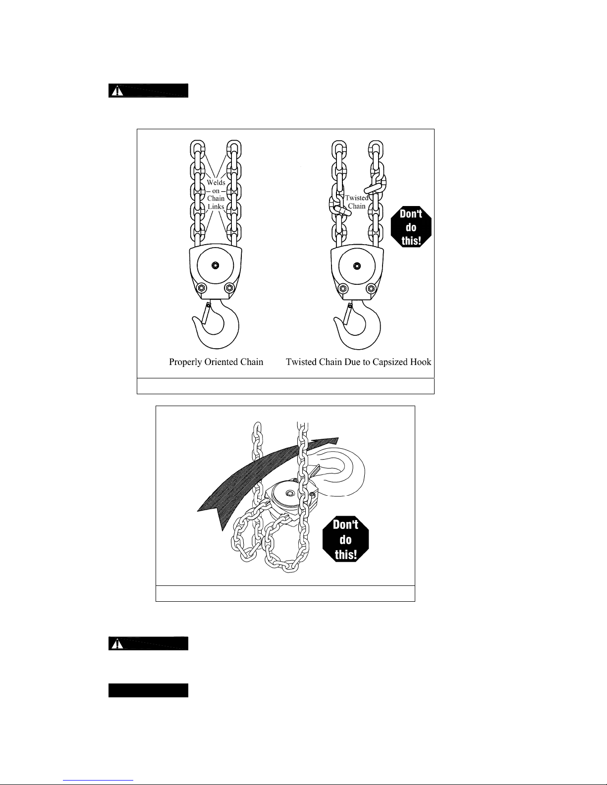
WARNING
Make sure the bottom hook on 2, 3 and 5 Ton double fall mod els is not capsized. Se e Figures 3-5 and
3-6. Correct all chain irregularities before condu cting the first hoist operation.
Verify that the load chain is not twisted or tangled prior to operating the hoist.
Figure 3-5 Twist in Load Chain – 2, 3 and 5 Ton Doubl e Fall Models
Figure 3-6 Capsized Hook and Chain –Double Fall Mo dels
3.3 Mounting Location
3.3.1
WARNING
structure are adequate to support the hoist and its loads. If necessary consult a p rofessional that is
qualified to evaluate the adequacy of the suspen sion location and its supp orting structu re.
Prior to mounting the hoist ensure that the suspensio n and the supporti ng
3.3.2
NOTICE
See Section 6.8 for outdoor installation considerations.
16

3.4 Mounting the Hoist
3.4.1 Manual Trolley - Follow instructions in Owner’s Ma nual provided with t he trolley.
3.4.2 Motorized Trolley - Follow instructions in O wner’s Manual provided with the trolley.
3.4.3 Hook Mounted to a Fixed Location - Attach the hoist’s top hook to the fixed suspension point.
3.4.4
WARNING
that the hook’s latch is engaged.
3.5 Electrical Connections
3.5.1
3.5.2
3.5.3
3.5.4
3.5.5
3.5.6
CAUTION
CAUTION
NER2 hoist. Use of such devices may cause the motor brake and other electrical compo nents to
malfunction. Variable frequency drives MAY be used with the single speed E R2/NER2 hoi sts, contact
Harrington Hoists, Inc. for more information.
DANGER
been de-energized (disconnected). Lock out and tag out in a ccordance with ANSI Z 244.1 “Personnel
Protection -Lockout/Tagout of Energy Sources”.
DANGER
maintenance on the dual speed ( VFD con trol) trolley or hoi st within 5 minute s of de-energizing
(disconnecting) the trolley or hoist. This time allows the internal VFD capacitor to safely discharge.
DANGER
operation.
CAUTION
and low lifting speeds. The speeds come preset from the factory (Se e Table 3-6). Speed (frequency)
can be customized. Refer to Section 3.6.10 for hoist sp ecific speed ra nges and instructi ons.
Ensure that the fixed suspension point rests on the center of the hook’s saddle and
Ensure that the voltage of the electric power supply is prope r for the hoist or trolley.
Do NOT apply electronic soft-start control or voltage varying controls to the ER2 or
Before proceeding, ensure that the electrical supply for t he hoist or trolley has
To avoid a shock hazard, DO NOT perform ANY mechanical or elect rical
Do NOT remove power to the dual speed (VFD control) hoi st or trolley during
All dual speed hoists are equiped with a VFD. The VFD is used to control the high
3.5.7 The following instructions apply when the h oist is hook mount ed to a fixed su spension point or install ed
on a manual trolley. The hoist is controlled by a pendant with two push buttons – one for raising and
one for lowering. Refer to the appropriat e trolley Owner’ s Manual if the hoist is install ed on a motorize d
trolley. Special wiring considerations must be taken if th e trolley is used with a troll ey other than an
MR2 model.
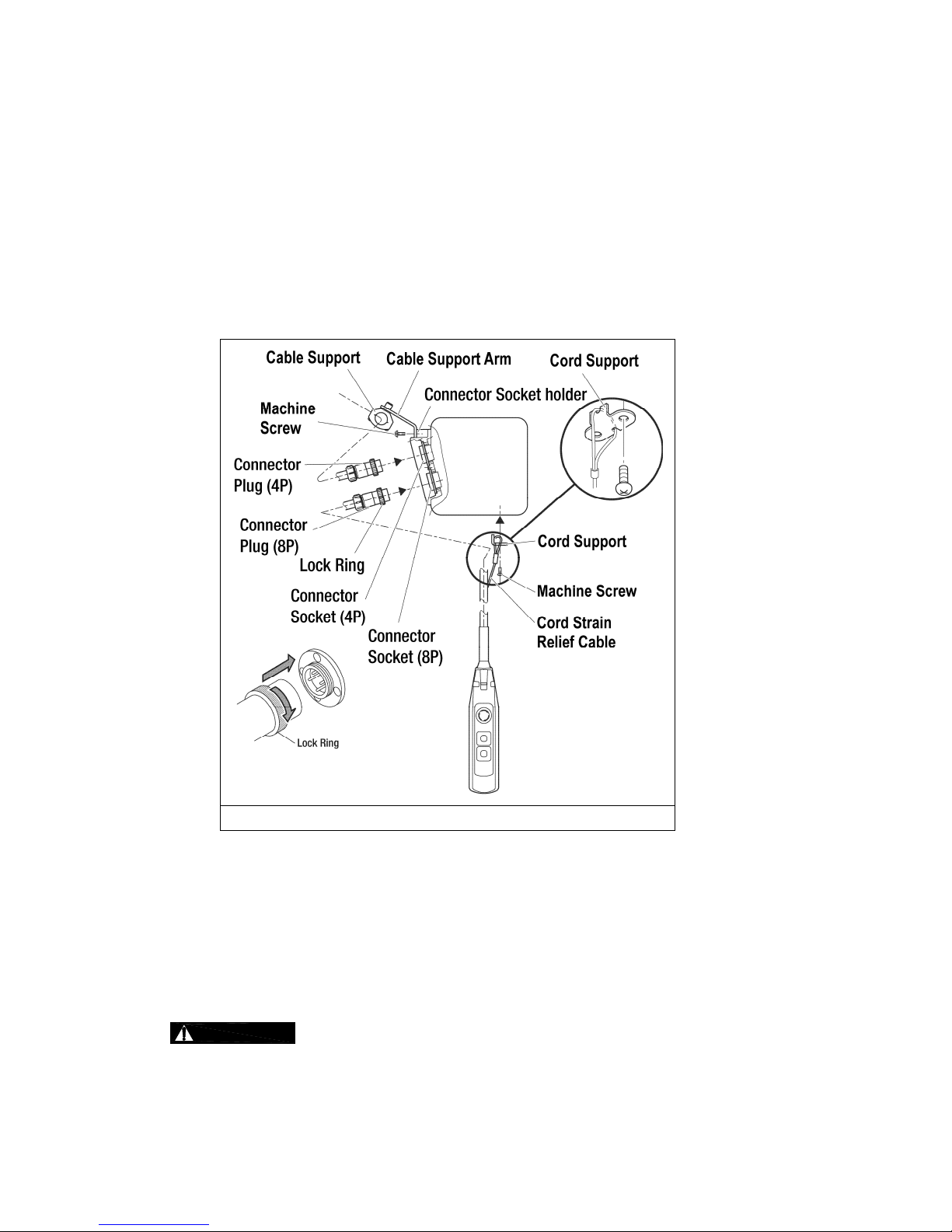
Pendant Cord
The Pendant Cord connects to the hoist via an 8-pin (8P) Plu g and Socket. Make this con nection
as follows:
Refer to Figure 3-7.
Insert the 8P Plug into the 8P Socket on the hoist and hand-tighte n the Lock Ring.
Attach the Cord Strain Relief Cable to the Cord Support on the bottom of the hoist.
Power Supply Cable - Hoist Connec tion
The Power Supply Cable connects to the hoi st via a 4-pin (4P) Pl ug and Socket. Make t his
connection as follows:
Refer to Figure 3-7.
Insert the 4P plug of the Power Supply Cable into the 4P Socket on the hoist and hand-ti ghten
the Lock Ring.
Install the Cable Support Arm (pre-installed on the Powe r Supply Cable) on to the Socket
Holder using the pre-installed Ma chine Screws and Lo ck Washers.
Use care to avoid twisting or kinking the Po wer Supply Cable.
17
Power Supply Cable - Installation
If the hoist is hook mounted to a fixed support ensure that the Power Supply Cable is properly
installed and supported between the hoi st and the ele ctrical power sup ply.
If the host is installed on a manual trolley, then the Power Supply Ca ble must be in stalled along th e
beam that the trolley runs on. For curved beams a special cable suspension system will be
needed, and this instruction does not appl y. For straight beams in stall the Power Su pply Cable as
follows:
Install a guide wire system parallel to the b eam.
For a manual trolley the guide wire should be positioned sli ghtly outside the hoist' s Cable
Support as shown in Figure 3-7.
Use the Cable Trolleys supplied with the hoi st to suspend the Po wer Supply Cable f rom the
guide wire. Space the Cable Trolleys every 5 fe et.
Figure 3-7 Pendant and Power Supply Cable Conn ections
3.5.8 Connection to Electrical Power Source - The red, blue and black wires of the Power Supp ly Cable
should be connected to an Electric Power Disconnect Switch or Circuit Breaker. This connection
should be made so that the hoist is phased properly. Refer t o Section 3.7.11 for instructions on how to
check for correct power supply phase connection.
3.5.9 Fuse/Breaker Capacity -The hoist's power su pply should be e quipped with current overl oad protection
such as fuses, which should be selected f or 110% to 120% of total listed full load am perage, and
should be dual element time-delay fuses. Ref er to the motor na meplate for the ful l load amperag e
draw.
3.5.10
DANGER
Grounding - An improper or insufficient gr ound connecti on creates an electrical
shock hazard when touching any part of the hoi st or trolley. In the Power Sup ply Cable the ground wire
will be either Green with Yellow stripe or solid Green. It should always be connect ed to a suitable
ground connection. Do not paint the trolley wheel ru nning surfa ces of the beam as this can affect
grounding.
18
3.6 VFD Setup (Dual Speed Only)
3.6.1
3.6.2
3.6.3 All dual speed hoists are equiped with a VFD. The VF D is used to co ntrol the high and low lifting
3.6.4 The VFD is controled by a Keypad/Display Interface. Refer to Figure 3-8 for Keypad/Display Interface
DANGER
maintenance on the dual speed ( VFD con trol) trolley or hoi st within 5 minute s of de-energizing
(disconnecting) the trolley or hoist. This time allows the internal VFD capacitor to safely discharge.
WARNING
operation.
speeds. The speeds come preset from the factory (Table 3-6). Speed (frequency) can be customized.
Refer to Section 3.6.10 for hoist spe cific speed range s and instructions.
functions and descriptions.
To avoid a shock hazard, DO NOT perform ANY mechanical or elect rical
Do Not remove power to the dual speed (V FD control) hoist or trolley duri ng
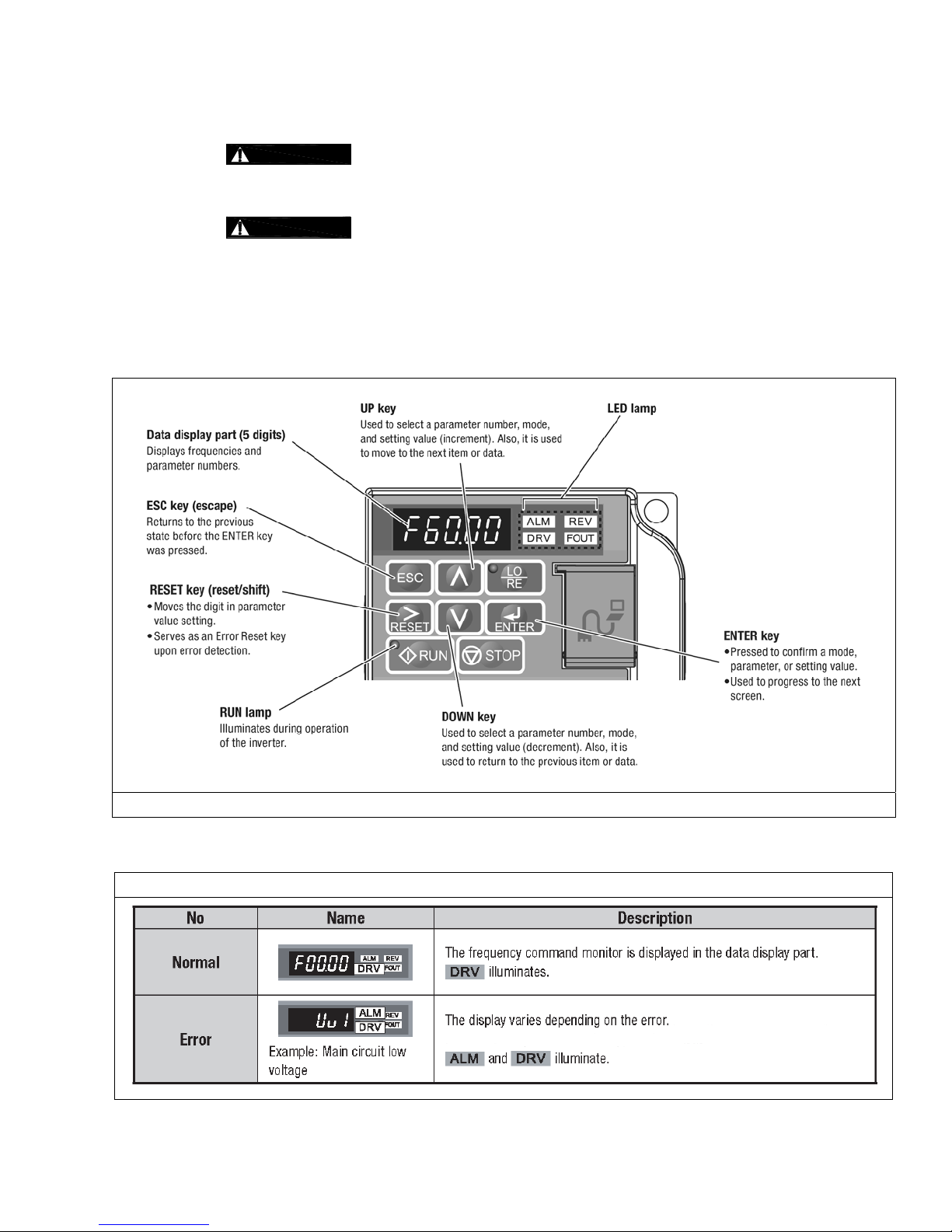
3.6.5 When power is supplied to the hoist the VFD LED operator display will illuminate as shown Table 3-2.
Figure 3-8 VFD Keypad/Display Interface
Table 3-2 LED Operator Display
19
Character
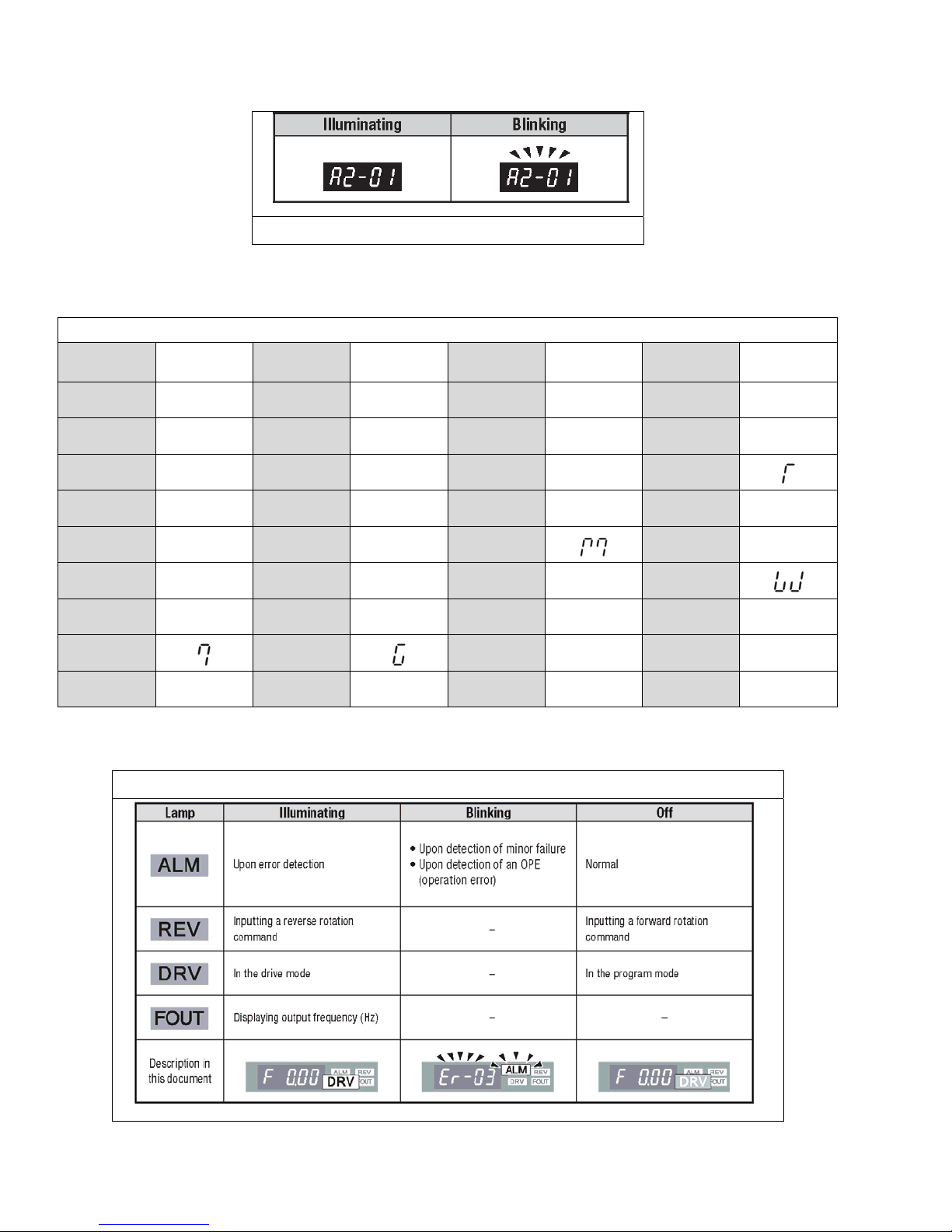
3.6.6 During operation the data display will exhi bit illuminating or blinking data as shown in Figu re 3-9.
Figure 3-9 Illuminating/Blinking Display
3.6.7 The digital display uses a seven segment character to form the spe cific charaters u sed in the display.
Table 3-3 shows the corresponding digita l characters t o its English eqi valent.
Table 3-3 Digital Character Key
Digital
Display
Character
Digital
Display
Character
Digital
Display
Character
Digital
Display
0
1
2
3
4
5
6
7
8
3.6.8 The LED Lamp display provides hoist status. Table 3-4 shows some of the status displays.
0
1
2
3
4
5
6
8
9
A
B
C
D
E
F
G
H
9
A
b
C
d
E
F
H
Table 3-4 LED Lamp Display
I
J
K
L
M
N
O
P
Q
i
J
t
L
N
o
P
q
R
S
T
U
V
W
X No Display
Y
Z No Display
r
S
U
v
Y
20
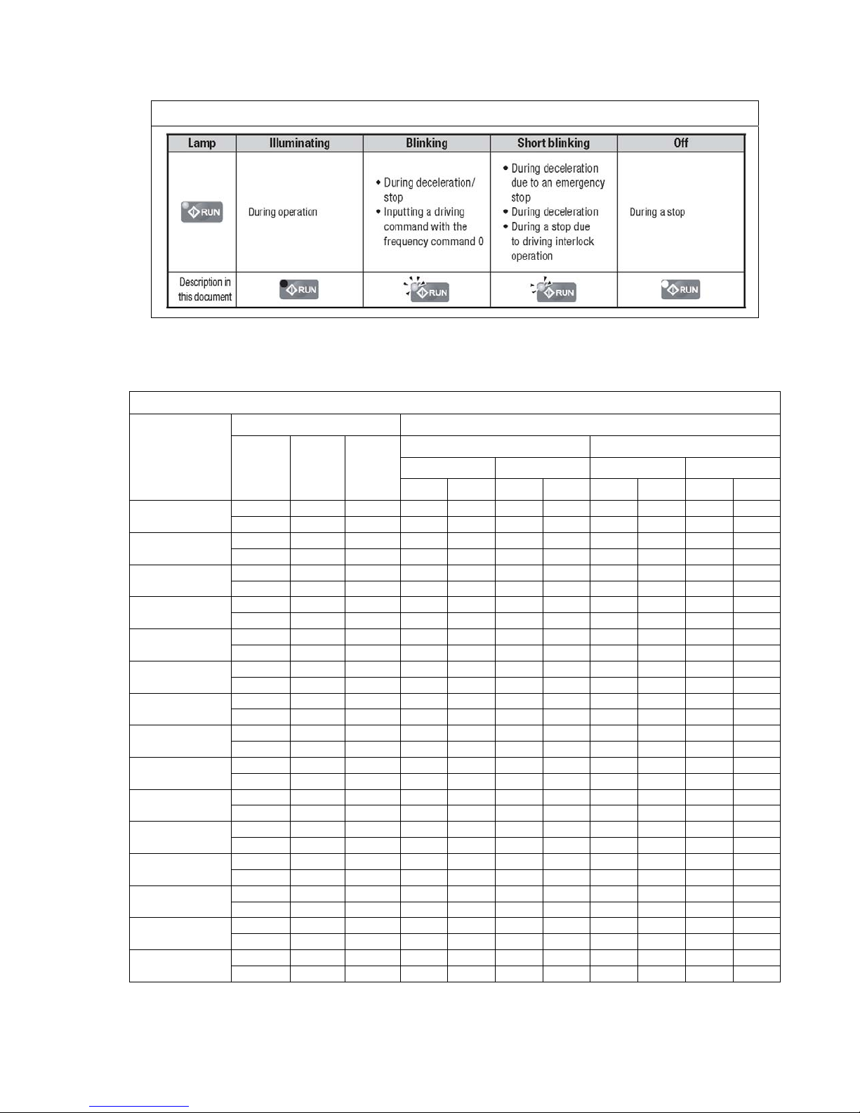
3.6.9 The Run Lamp display provides hoist “RUN” status. Table 3-5 shows the various “RUN” displays.
Table 3-5 Run Lamp
3.6.10 All of the hoists have speed/frequency ranges that can be customi zed to a specifi c application. Ref er
to Table 3-6 for specific hoist speed/frequency ranges. To set cu stom speeds for an a pplication, follow
the procedure listed in Table 3-7.
Table 3-6 VFD Speed & Frequency Ranges
Hoist Speed (ft/min) VFD Frequency (Hz)
Product Code
(N)ER2001HD
(N)ER2003SD
(N)ER2003HD
(N)ER2005LD
(N)ER2005SD
(N)ER2010LD
(N)ER2010SD
(N)ER2015SD
(N)ER2020CD
(N)ER2020LD
(N)ER2020SD
(N)ER2025SD
(N)ER2030LD
(N)ER2030CD
(N)ER2050LD
*Low = The minimum and maximum speed/frequency range (12:1 ratio).
Std = The factory standard minimum and maximum speed/frequency range (6:1 ratio).
Range* Low High
Low 4.5 55 3.2 3.3 57.0 57.0 4.9 3.3 57.5 57.0
Std 9.0 55 8.3 8.2 57.0 57.0 9.7 7.8 57.5 57.0
Low 3.0 36 3.2 3.3 57.0 57.0 4.9 3.3 57.5 57.0
Std 6.0 36 8.3 8.2 57.0 57.0 9.7 7.8 57.5 57.0
Low 4.3 53 2.6 2.5 53.5 54.0 2.8 2.5 55.0 54.0
Std 9.0 53 7.3 7.3 53.5 54.0 8.0 7.2 55.0 54.0
Low 1.2 15 3.2 3.3 57.0 57.0 4.9 3.3 57.5 57.0
Std 2.5 15 8.3 8.2 57.0 57.0 9.7 7.8 57.5 57.0
Low 2.3 29 2.6 2.5 53.5 54.0 2.8 2.5 55.0 54.0
Std 5.0 29 7.3 7.3 53.5 54.0 8.0 7.2 55.0 54.0
Low 1.1 14 2.6 2.5 53.5 54.0 2.8 2.5 55.0 54.0
Std 2.5 14 7.3 7.3 53.5 54.0 8.0 7.2 55.0 54.0
Low 2.2 28 2.3 2.1 53.0 53.5 2.7 3.0 53.0 53.5
Std 4.5 28 7.3 7.0 53.0 53.5 8.2 7.5 53.0 53.5
Low 1.4 18 2.3 2.1 53.0 53.5 2.7 3.0 53.0 53.5
Std 3.0 18 7.3 7.0 53.0 53.5 8.2 7.5 53.0 53.5
Low 0.5 7.0 2.6 2.5 53.5 54.0 2.8 2.5 55.0 54.0
Std 1.0 7.0 7.3 7.3 53.5 54.0 8.0 7.2 55.0 54.0
Low 1.0 14.0 2.3 2.1 53.0 53.5 2.7 3.0 53.0 53.5
Std 2.5 14.0 7.3 7.0 53.0 53.5 8.2 7.5 53.0 53.5
Low 2.2 28 2.6 3.0 54.0 55.0 2.8 3.0 52.0 55.0
Std 4.5 28 7.9 7.7 54.0 55.0 8.0 7.7 52.0 55.0
Low 1.8 22 2.6 3.0 54.0 55.0 2.8 3.0 52.0 55.0
Std 3.5 22 7.9 7.7 54.0 55.0 8.0 7.7 52.0 55.0
Low TBD TBD TBD TBD TBD TBD TBD TBD TBD TBD
Std TBD TBD TBD TBD TBD TBD TBD TBD TBD TBD
Low 1.4 17 2.6 3.0 54.0 55.0 2.8 3.0 52.0 55.0
Std 3.0 17 7.9 7.7 54.0 55.0 8.0 7.7 52.0 55.0
Low 0.9 11 2.6 3.0 54.0 55.0 2.8 3.0 52.0 55.0
Std 2 11 7.9 7.7 54.0 55.0 8.0 7.7 52.0 55.0
Low (d1-01) High (d1-02) Low (d1-01) High (d1-02)
230V 460V 230V 460V 230V 460V 230V 460V
NER2 ER2
21
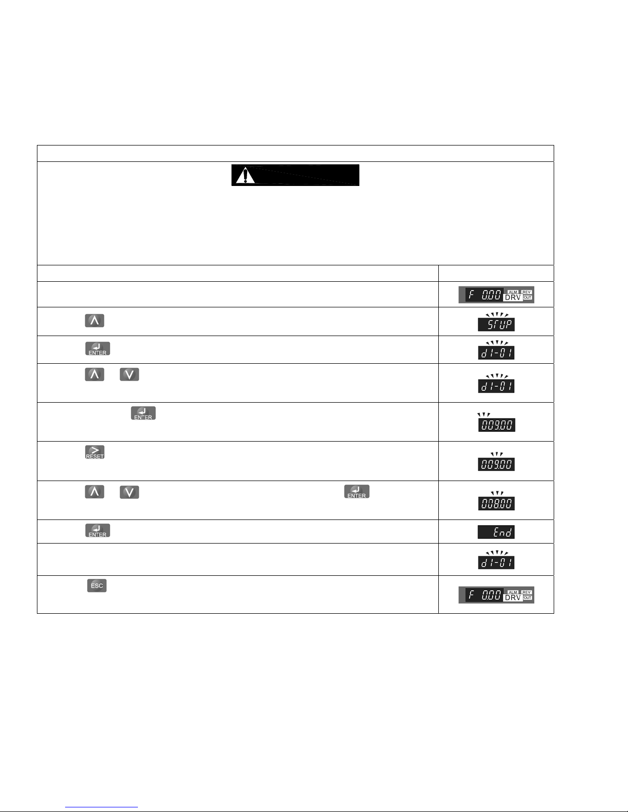
Table 3-7 Dual Speed Hoist (w/VFD) Sp eed/Frequen cy Chang e Procedure
CAUTION
Each dual speed hoist model has a range of available speeds/frequencies (upper and lower limits). Any
value outside the range listed in T able 3-6 for your specifi c hoist is strictl y prohibited.
Speeds must be set such as Low [d1-01] and High [d1-02].
After parameters are changed, a “no load” operational check must be performed.
Operational Step VFD Display
1. Energize the hoist.
2. Press until the “Setup Mode” screen is displayed (blinking).
3. Press to display the parameter setting screen (blinking).
4. Press or until the desired parameter is displayed (blinking).
(Low Speed: d1-01, High Speed: d1-02)
5. When you press , the current setting value is displayed (digit selected blinks).
(Example Value: 9 Hz)
6. Press to move the blinking digit to the desi red digit.
(Example Value: 9 blinks)
7. Press or until the desired setting is displayed and press .
(Example Value: 8 Hz)
8. Press to confirm the new setting.
9. The display will automatically return to the parameter screen (blinking).
(As in Step 4.)
10. Press until the diplay returns to the initial screen.
(As in Step 1.)
22
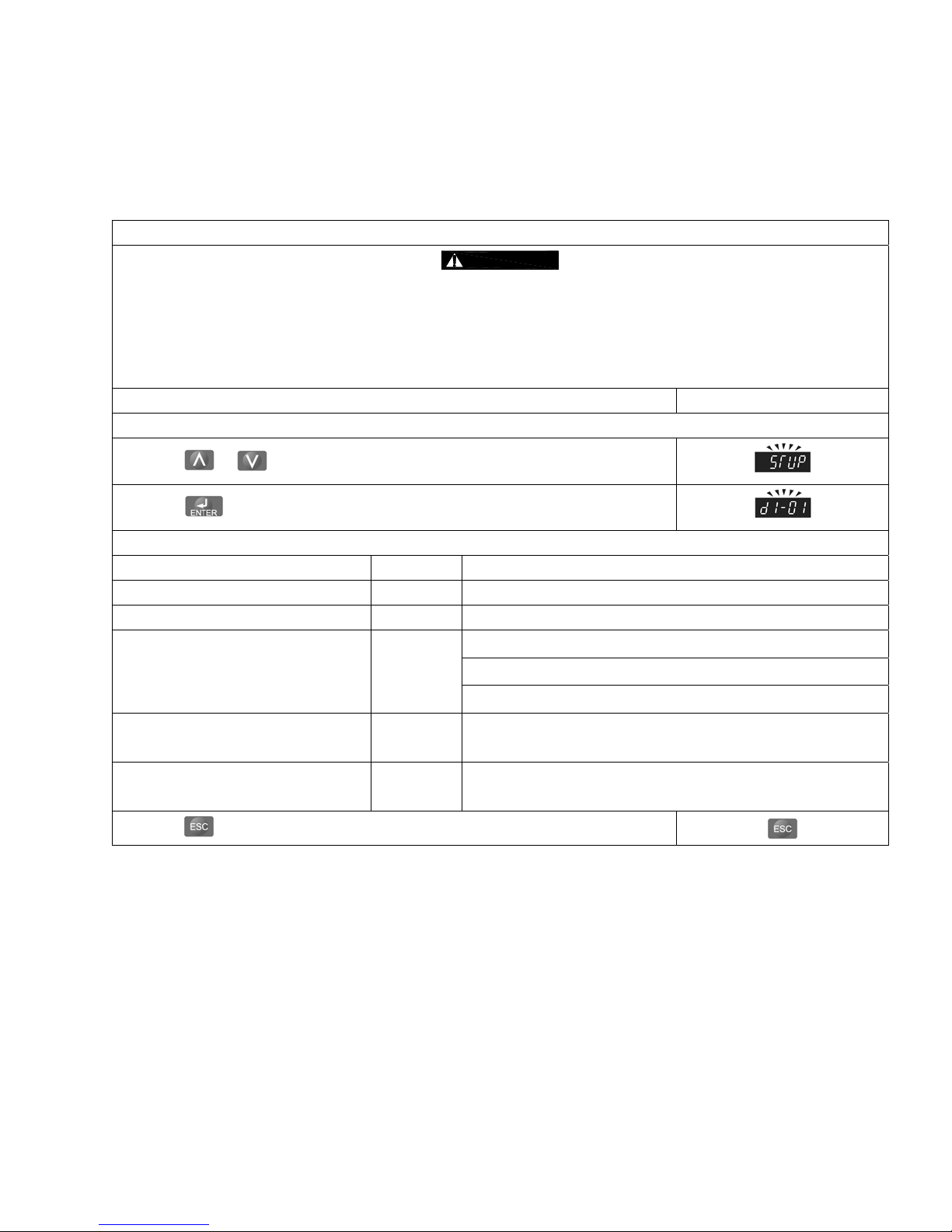
Table 3-8 Hoist VFD 2-Step/3-Step Infin itely Variable Parameter Setup P rocedure
CAUTION
Each VFD controlled hoist model has a range of avail able spee ds/frequencies (upper and lo wer limits).
Refer to Table 3-6 for a list of accepta ble speeds/frequen cies.
Any value outside the range listed in Table 3-6 for y our specific hoist is strictly prohi bited.
Speeds must be set such as Low [d1-01] and High [d1-02].
After parameters are changed, a “no load” operational check must be performed.
Operational Step VFD Display
Change Mode to 2 Step or 3 Step.
1. Press or until the “Setup Mode” screen is displayed (blinking).
2. Press to display “d1-01”.
3. Table 3-6 lists the values that may be changed.
Title Parameter Description
Min. Frequency (Hz) – Low Speed d1-01 Default setting, dependant upon hoist. (Refer to Table 3-7)
Max. frequency (Hz) – High Speed d1-02 Default setting, dependant upon hoist. (Refer to Table 3-7)
1. Standard 2 Speed (default)
Mode S1-25
Acceleration Time (sec.)
(0 to 120 Hz) in 2 or 3 Step Mode.
Deceleration Time (sec.)
(0 to 120 Hz) in 3 Step Mode.
S1-26 Apply for frequency range between d1-01 and d1-02.
S1-27 Apply for frequency range between d1-01 and d1-02.
2. 2 Step Infinitely Variable
3. 3 Step Infinitely Variable (Requires optional hardware)
4. Press several times.
3.6.11 “Hbb” will appear on the dual speed unit’s VFD displ ay when the Emergency Stop B utton is depressed.
Turn the Emergency Stop Button clockwise to unlock the controls and allow hoist operation.
23

3.7 Preoperational Checks and Trial Operation
3.7.1
3.7.2
3.7.3 Measure and record the “k” dimension of all hooks on hoist. See Ta ble 5-4 under Section 5,
3.7.4 Record the hoist's Code, Lot and Serial Number (from th e name plate on the ho ist; see Section 1 0) in
3.7.5 Ensure that the hoist is properly installed to either a fixe d point, or trolley, whichev er applies.
3.7.6 If hoist is installed on a trolley, ensure that
3.7.7 Ensure that all nuts, bolts and split pins (cotter pins) are suffici ently fastened.
3.7.8 Pull down on the Pendant and ensure that the Cord Strain Relief Cable takes t he force, not the
3.7.9
WARNING
other lifting attachments before use. Inspect all load suspension m embers for da mage prior to us e and
replace or repair all damaged parts.
WARNING
Section 3.2.
“Inspection”.
the space provided on the cover of this manual.
trolley is properly installed on the beam, and
stops for the trolley are correctly positioned and securely installed on the beam.
Pendant Cord.
CAUTION
the rated value, electrical devices may not function normally.
Confirm the adequacy of the rated capacity for all slings, chain s, wire ropes and all
Verify and correct all chain irregularities prior to op erating the hoist. Ref er to
Check supply voltage before everyday use. If the voltage vari es more than 10% of
3.7.10 Confirm proper operation.
Before operating read and become familiar with Section 4 - Operation.
Before operating ensure that the hoist (and trolley) meets the Inspection, Testing and Maint enance
requirements of ANSI/ASME B30.16.
Before operating ensure that nothing will interfere with the full range of the hoist’s (and trolley’s)
operation.
3.7.11
WARNING
operation corresponds to the up-and-down commands is sued from the pe ndant cont rol; i.e. pushing the
UP button must cause the hoist to lift the load chain and hook. If the h oist does not ope rate correctly,
shut off and lockout /tagout the main power sou rce to the hoist
three input power leads at the power sou rce to correct the hoist’s m otor phasing.
The hoist must be connected to the power source su ch that its direct ion of
. Disconnect and switch any two of the
24
4.0 Operation
4.1 Introduction
DANGER
DO NOT
WALK UNDER A SUSPENDED LOAD
WARNING
HOIST OPERATORS SH ALL BE REQUIRED TO READ THE OPERATION SECTION OF THIS MANUAL, THE
WARNINGS CONTAINED IN THIS MANUAL, INSTRUCTION AND WARNING LABELS ON THE HOIST OR
LIFTING SYSTEM, AND THE OPERATION SECTIONS OF ANSI/ASME B30.16 and ANSI/ASME B30.10. THE
OPERATOR SHALL ALSO BE REQUIRED TO BE FAMILIAR WITH THE HOIST AND HOIST CONTROLS
BEFORE BEING AUTHORIZED TO OPERATE THE HOIST OR LIFTING SYSTEM.
HOIST OPERATORS SHOULD BE TRAINED IN PROPER RIGGING PROCEDURES FOR THE ATTACHMENT
OF LOADS TO THE HOIST HOOK.
HOIST OPERATORS SHOULD BE TRAINED TO BE AWARE OF POTENTIAL MALFUNCTIONS OF THE
EQUIPMENT THAT REQUIRE ADJUSTMENT OR REPAIR, AND TO BE INSTRUCTED TO STOP OPERATION
IF SUCH MALFUNCTIONS OCCUR, AND TO IMMEDIATELY ADVISE THEIR SUPERVISOR SO CORRECTIVE
ACTION CAN BE TAKEN.
HOIST OPERATORS SHOULD HAVE NORMAL DEPTH PERCEPTION, FIELD OF VISION, REACTION TIME,
MANUAL DEXTERITY, AND COORDINATION.
HOIST OPERATORS SHOULD NOT
PHYSICAL CONTROL, PHYSICAL DEFECTS, OR EMOTIONAL INSTABILITY THAT COULD RESULT IN
ACTIONS OF THE OPERATOR BEING A HAZARD TO THE OPERATOR OR TO OTHERS.
HOIST OPERATORS SHOULD NOT
INFLUENCE OF ALCOHOL, DRUGS, OR MEDICATION.
OVERHEAD HOISTS ARE INTENDED ONLY FOR VERTICAL LIFTING SERVICE OF FREELY SUSPENDED
UNGUIDED LOADS. DO NOT
ARE NOT FREELY SUSPENDED, OR LOADS THAT ARE GUIDED.
USE HOIST FOR LOADS THAT ARE NOT LIFTED VERTICALLY, LOADS THAT
HAVE A HISTORY OF OR BE PRONE TO SEIZURES, LOSS OF
OPERATE A HOIST OR LIFTING SYSTEM WHEN UNDER THE
• Read ANSI/ASME B30.16 and ANSI/ASME B30.10.
• Read the hoist manufacturer’s Operating and Mai ntenance Instructi ons.
• Read all labels attached to equipment.
NOTICE
25
The operation of an overhead hoist involves more than activating the hoist’s controls. Per the ANSI/ASME B30
standards, the use of an overhead hoist is subject to certain hazards that cannot be mitigated by engineered features,
but only by the exercise of intelligence, care, common sense, and experience i n anticipating the eff ects and result s of
activating the hoist’s controls. Use this guidance in conjunction with ot her warnings, ca utions, and notice s in this manual
to govern the operation and use of your overhead hoist.
4.2 Shall’s and Shall Not’s for Operation
WARNING
Improper operation of a hoist can create a potentially hazar dous situation which, if
not avoided, could result in death
To avoid such a potentially hazardous situation THE OPERATOR SHALL:
• NOT
• NOT
• Be familiar with operating controls, procedures, and
• NOT
• NOT
• NOT
• NOT
• NOT
• NOT
• NOT
• NOT
• Protect the hoist’s load chain from weld splatter or
• NOT
• NOT
• NOT
operate a damaged, malfunctioning or
unusually performing hoist.
operate a hoist until you have thoroughly read
and understood Manufacturer’s Operating and
Maintenance Instructions or Manuals.
warnings.
operate a hoist that has been modified without
the manufacturer’s approval or without certification
that it is in conformity with ANSI/ASME B30
volumes.
lift more than rated load for the hoist.
use hoist with twisted, kinked, damaged, or
worn load chain.
use the hoist to lift, support, or transport
people.
lift loads over people.
operate a hoist unless all persons are and
remain clear of the supported load.
operate unless load is centered under hoist.
attempt to lengthen the load chain or repair
damaged load chain.
other damaging contaminants.
operate hoist when it is restricted from forming
a straight line from hook to support in the direction
of loading.
use load chain as a sling or wrap load chain
around load.
apply the load to the tip of the hook or to the
hook latch.
or serious injury, and substantial property damage.
• NOT
• NOT
• NOT
• NOT
• NOT
• NOT
• NOT
• NOT
• NOT
• NOT
• NOT
• Take up slack carefully – make sure load is
• Shut down a hoist that malfunctions or performs
• Make sure hoist limit switches function properly.
• Warn personnel before lifting or moving a load.
• Warn personnel of an approaching load.
apply load unless the load chain is properly
seated in its grooves.
apply load if bearing prevents equal loading
on all load-supporting chain.
operate beyond the limits of the load chain
travel.
leave load supported by the hoist unattended
unless specific precautions have been taken.
allow the load chain or hook to be used as an
electrical or welding ground.
allow the load chain or hook to be touched by
a live welding electrode.
remove or obscure the warnings on the hoist.
operate a hoist on which the safety placards
or decals are missing or illegible
operate a hoist unless it has been securely
attached to a suitable support.
operate a hoist unless load slings or other
approved single attachments are properly sized,
and seated in the hook saddle.
use the hoist in such a way that could re sult in
shock or impact loads being applie d to the hoist.
balanced and load-holding action is secure before
continuing.
unusually and report such malfunction.
26

CAUTION
Improper operation of a hoist can create a potentially hazar dous situation
which, if not avoided, could result in minor
property damage. To avoid such a potentially hazardous situation THE
OPERATOR SHALL:
• Maintain a firm footing or be otherwise secured
when operating the hoist.
• Check brake function by tensioning the hoist prior
to each lift operation.
• Use hook latches. Latches are to retain slings,
chains, etc. under slack conditions only.
• Make sure the hook latches are closed and not
supporting any parts of the load.
• Make sure the load is free to move and will clear all
obstructions.
• Avoid swinging the load or hook.
• Make sure hook travel is in the same direction as
shown on controls.
• Inspect the hoist regularly, replace damaged or
worn parts, and keep appropriate records of
maintenance.
or moderate injury, or
• Use the hoist manufacturer’s recommended parts
when repairing the unit.
• Lubricate load chain per hoist manufacturer’s
recommendations.
• NOT
• NOT
• NOT
• NOT
• NOT
use the hoist load limiting or warning device to
measure load.
use limit switches as routine operating stops.
They are emergency devices only.
allow your attention to be diverted from
operating the hoist.
allow the hoist to be subjected to sharp
contact with other hoists, structures, or objects
through misuse.
adjust or repair the hoist unless qualified to
perform such adjustments or repairs.
27
4.3 Hoist Controls
4.3.1 For hoists mounted to motorized trolleys follo w
the control instruction included in the trolley's
Owner's Manual.
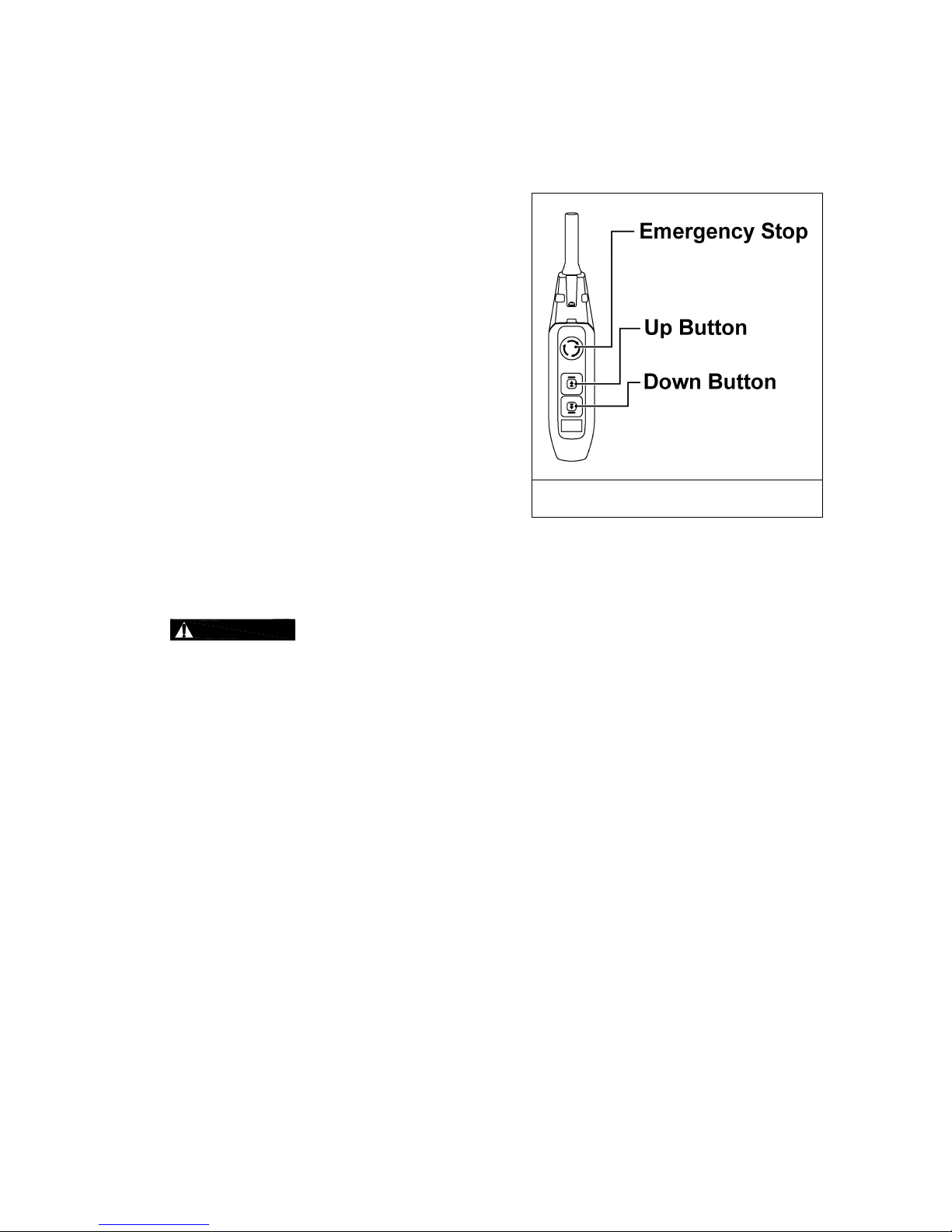
4.3.2 Emergency Stop Button – Press the Emergency
Stop Button to perform an emergency stop and
lock-out of hoist motion controls or to reset the
VFD as shown in Figure 4-1. Turn the
Emergency Stop Button clockwise to unlock the
controls and allow hoist operation. “Hbb” will
appear on the dual speed unit’s VFD display
when the Emergency Stop Button is depressed.
4.3.3 Single Speed Pendant Control – When using
the pendant control depress the UP button to
raise the hoist load chain/hook or the DOWN
button to lower the hoist load chain/hook as
shown in Figure 4-1. To stop motion release
the buttons.
4.3.4 Dual Speed Pendant Control – Pendant
controls supplied with dual speed hoists have
two step control buttons. For low speed
depress the button to the first step and for high
speed depress the button fully to the second
step. Use the UP button to raise the hoist load
chain/hook or the DOWN button to lower the
hoist load chain/hook as shown in Figure 4-1.
To stop motion release the buttons.
Figure 4-1 Push Button Pendant Control
4.3.5
CAUTION
completely stops before reversing direction.
Make sure the motor
28

5.0 Inspection
5.1 General
5.1.1 The inspection procedure herein is based on ANSI/ASME B30.16. The following definitions are from
ANSI/ASME B30.16 and pertain to the inspection procedure below.
Designated Person – a person selected or assigned as being competent to pe rform the specifi c duties
to which he/she is assigned.
Qualified Person – a person who, by possession of a recognized degree or certificate of p rofessional
standing, or who, by extensive knowledge, train ing, and experience, has successf ully demonstrated the
ability to solve or resolve problems relating to the subject matter and work.
Normal Service – that distributed service which involves operation with ran domly distrib uted loads
within the rated load limit, or uniform loads less than 65% of rated load for not more than 25% of the
time.
Heavy Service – that service which involves operation within the rated load limit which exceeds normal
service.
Severe Service – that service which involves normal or heavy service with abnorm al operating
conditions.
5.2 Inspection Classification
5.2.1 Initial Inspection – prior to initial use, all new, altered, or modifi ed hoists shall be inspect ed by a
designated person to ensure compliance with the applicable pr ovisions of this manual.
5.2.2 Inspection Classification – the inspection procedure for hoists in regular service is divided into two
general classifications based upo n the intervals at which i nspection sho uld be perform ed. The intervals
in turn are dependent upon the nature of the criti cal components of the hoist and the deg ree of their
exposure to wear, deterioration, or malfunction. The two general classificati ons are herein designated
as FREQUENT and PERIODIC, with respectiv e intervals betwee n inspections as de fined below.
5.2.3 FREQUENT Inspection – visual examinations by the operator o r other designated perso nnel with
intervals per the following criteria:
Normal service – monthly
Heavy service – weekly to monthly
Severe service – daily to weekly
Special or infrequent service – as recommended by a qualified person bef ore and after each
occurrence.
5.2.4 PERIODIC Inspection – visual inspection by a designat ed person with interval s per the followin g
criteria:
Normal service – yearly
Heavy service – semiannually
Severe service – quarterly
Special or infrequent service – as recommended by a qualified person before the fi rst such
occurrence and as directed by the qualified perso n for any subsequ ent occurrences.
29
 Loading...