

Page 1

R
Turf Sweeper
& Parts Manual
TV 30
7/11
R
R
Page 2

R
TV 30
Page 3

Thank you for purchasing a Harper Turf Vac.
As with all Harper products, the Turf Vac has been developed through tough design and testing
procedures to produce a top quality machine. This manual gives assembly, operating, and service
information for the model TV30 Turf Vac. Please read and understand all instructional material
included with the Turf Vac or its components before assembling and operating the equipment.
A Turf Vac can present hazards to an operator who follows unsafe procedures in either the
operation or maintenance of the unit. Therefore, SAFETY WARNINGS are presented at certain
locations in the text.
THIS SYMBOL: SAFETY WARNING!
MEANING: Failure to understand and obey this warning may result in injury to you or others.
Whenever this symbol is used, please pay very close attention to the information presented, and
make sure you fully understand. If you do not, contact your dealer or Harper Industries, Inc. for
clarication.
SAFETY WARNING!
ALL SHIELDS AND GUARDS MUST BE IN PLACE FOR PROPER AND SAFE OPERATION
OF THIS EQUIPMENT. WHERE THEY ARE SHOWN REMOVED IN THIS MANUAL, IT IS FOR
PURPOSES OF ILLUSTRATION AND INSTRUCTION ONLY. DO NOT OPERATE THIS
EQUIPMENT UNLESS ALL SHIELDS AND GUARDS ARE IN PLACE.
Harper Industries, Inc. is continually striving to improve the design and performance of its
products. We reserve the right to make changes in specications and design without thereby
incurring any obligation relative to previously manufactured products.
The Harper name is a registered trademark of Harper Industries, Inc. All other brand and product
names are trademarks or registered trademarks of their respective companies.
TV 30
© 2011 Harper Industries, Inc.
R
1
Page 4

LIMITED WARRANTY
The Harper TV30 Turf Vac is warranted against defects in workmanship
and materials for a period of TWELVE MONTHS from the original date of retail
purchase to the original purchaser.
Harper Industries will repair or replace, at our option, any part which our
examination shows to be defective. Warranty is limited to parts, labor and
ground freight delivery of replacement parts. The user will pay freight
charges for parts submitted under this warranty.
No product or part may be returned for warranty consideration without
prior approval from Harper Industries.
This warranty does not apply to parts subjected to misuse, abuse,
alteration, improper or inadequate maintenance, or normal wear (including
belts and broom).
Engines are not covered under this warranty. Refer to manufacturer’s
warranty for specic warranty information. Harper Industries, its agents or
representatives, make or imply no other warranties.
RECORDS
Date of Purchase ______ / ______ / ______
Dealer’s Name _________________________________
Dealer’s Phone _________________________________
Serial Number Machine __________________________
Serial Number Engine ___________________________
R
2
TV 30
Page 5

Table of Contents
OPERATOR SECTION
To the Owner or Operator............................................
Warranty Statement......................................................
Table of Contents..........................................................
Specications................................................................
Control Identication
ROPS...............................................................
Steering Wheel.................................................
Control Panel....................................................
Foot Pedal........................................................
Lift Mechanism.................................................
Fan Housing.....................................................
Sweeper Deck..................................................
Engine..............................................................
Hopper..............................................................
Hopper Door.....................................................
Stabilizer Arms (2)............................................
Hopper Lift Height Decal..................................
Fan ON/OFF.....................................................
Broom ON/OFF.................................................
Hopper ON/OFF................................................
Door OPEN/CLOSE.........................................
Operation Speed HI/LO....................................
Park Brake ON/OFF..........................................
Park Brake Indicator.........................................
Engine Choke (diesel)......................................
Deck Lift............................................................
Throttle.............................................................
Ignition..............................................................
Empty Lift Cylinder............................................
Safety Lock.......................................................
Impeller.............................................................
Liner..................................................................
Mercury Switch.................................................
Safety Guideline
Equipment & Controls......................................
Safety Decals...................................................
Gasoline...........................................................
Guards & Shields..............................................
Battery..............................................................
Hydraulics.........................................................
Before Operation..............................................
During Operation..............................................
Maintenance
Hydraulic System.............................................
Grease Zerk Location.......................................
Air Cleaner........................................................
Cooling System................................................
Engine Oil.........................................................
Fuel Filter..........................................................
Relay Panel......................................................
Standard Torque Chart.................................................
Maintenance Schedule.................................................
10
11
11
12
12
13
13
13
14
PARTS SECTION
Table of Contents
Frame and Engine
Frame Assembly..............................................
Control Arm Assembly.....................................
1
2
3
4
5
5
5
5
5
5
5
5
5
5
5
6
6
6
6
6
6
6
6
6
6
6
6
7
7
7
7
7
8
8
8
8
9
9
9
9
Front Axle Assembly........................................
Engine and Tank Installation...........................
Diesel Engine Assembly..................................
Fuel Tank Assembly.........................................
Engine Shield Assembly..................................
Deck Assembly................................................
Deck Installation..............................................
Broom Kit.........................................................
Finger Kit.........................................................
Verticut/Dethatch Kit........................................
Fan Housing & Hydraulic Cooler Assy.............
Fan Housing Installation..................................
Outrigger Installation.......................................
Hopper and Door Assembly.............................
Hopper Installation..........................................
Operator Station..............................................
Hydraulic
Hydraulic Reservoir Assembly.........................
Wheel Motor Assembly....................................
Propulsion Pump Assembly.............................
Triple Section Pump Assembly........................
Master Valve Assembly....................................
Propulsion Valve Assembly..............................
Sequence Valve Assembly..............................
Pressure Reduction Valve Assembly...............
Hydraulic Cylinder Service Parts.....................
Propulsion System..........................................
Wheel Motor Plumbing.....................................
Steering System..............................................
Propulsion Suction & Drain Plumbing.............
Machine System..............................................
Triple Section Pump Plumbing........................
Deck Plumbing................................................
Fan Motor Plumbing........................................
Outrigger Plumbing.........................................
Hopper Plumbing............................................
Port Label Abbreviations.................................
Electrical
Wiring Schematic Diagram Overview..............
Master Harness...............................................
Engine Harness...............................................
Gauge Harness...............................................
Hydraulic Coller Fan Harness.........................
Relay Harness.................................................
Ignition Harness..............................................
Electrical Assemblies.......................................
Light Package Installation (Optional)...............
1.1
1.2
1.3
1.4
1.5
1.6
1.7
1.8
1.9
1.10
1.11
1.12
1.13
1.14
1.15
1.16
1.17
1.18
2.1
2.2
2.3
2.4
2.5
2.6
2.7
2.7
2.8
2.9
2.10
2.11
2.12
2.13
2.14
2.15
2.16
2.17
2.18
2.19
3.1
3.2
3.3
3.4
3.5
3.6
3.7
3.8
3.9
TV 30
R
3
Page 6

Specications
Power Diesel - Kubota 44 hp 4-Cylinder (available Spring 2010)
Conguration Self-contained, 4-wheel conguration with front steering, two rear
drive wheels, and a rear mounted, high-lift, debris hopper with patented
recirculating vacuum air technology
Sweeper Head 60” single sweeping reel with nylon bristle brush, follows all terrain with two
caster wheels mounted on sweeper head (vertical and horizontal oat), rises to
transport position, lowers to operating position by hydraulic cylinder
Fan 25” diameter with 6-blade radial fan, fan housing includes UHMW liner
Debris Hopper Capacity – 3.5 cubic yards
Stabilizers Two side stabilizers, auto-deploy
Lift Rises 6’4” above the ground to dump debris into vehicle or container
Lift Safety Slope sensor (7% grade) and lift capacity sensor
Drive Hydrostatic pump directly coupled to engine drives two Poclain high-efciency pis -
ton drive hydraulic motors on rear wheels with two speed operation and differential
lock, foot operated pedal for forward and reverse drive
Speed Innitely variable, 0-8 mph low (operation), 0-14 mph high (transport), 0-7 mph
reverse Braking Dynamic braking through the hydrostatic drive system, mechani-
cally applied and hydraulically released parking brake on rear wheels
Main Frame ¼” and 7 gauge steel frame
Tires/Wheels Front (2) 20-10x10 4-ply premium turf tire, Rear (2) 26-12x12 6-ply premium turf
tires
Compaction 11.2 psi in front, 7.8 psi in rear
Steering Power steering with automotive type steering wheel, tilt steering
Controls/Gauges Hydraulic lift/lower of debris hopper
Hydraulic open/close of debris hopper tailgate
Hydraulic raise/lower of sweeping mechanism head assembly
Solid State max grade detection for dump circuit
Seat Tethered, high back, adjustable position
Electrical 12 volt, electronic key start
Dimensions Length – 144 in., Height – 89 in., Width – 65 in., Wheel Base – 84 in.
Weight 4260 lbs.
Liquid Capacities Fuel – 11 Gallon; Hydraulic Fluid – 19 Gal
Safety & Includes Certied ROPS and seatbelt, outriggers for safety during dumping and a
Conformance solid state max grade detection system for dumping system
Hydraulic Oil Terresolve EL 3068, bio-based, high-performance, ISO 68 – viscosity, severe ser-
vice
NOTE: Following publication of this manual, certain changes in standard equipment and/or options
may have occurred which would not be included in these pages. Your Harper dealer is the
best source for up-to-date information.
R
4
TV 30
Page 7

Control Identication
ROPS – Roll-Over Protective Structure is
certied and designed to protect operator in
case of a roll-over. Always wear a safety belt.
Steering Wheel – steering is hydraulically
controlled. Turning radius of the sweeper
head is approximately 46 in. Steering wheel
angle may be adjusted with tilt knob.
Control Panel –
all functions of the turf
vac may be controlled
from the operator’s seat.
ROPS
HOPPER
HOPPER
DOOR
Foot Pedal –
hydrostatic pump is
controlled by pushing
STEERING
WHEEL
foot pedal forward
and backward.
CONTROL
PANEL
Lift Mechanism –
raises the bottom of
the hopper to a
height of 6’4” to
FOOT PEDAL
dump into a
vehicle or container.
Use extreme caution
when raising the
hopper as the top can
reach approximately 13½ feet.
Fan Housing – surrounds the impeller and is
protected on the inside by a plastic liner.
MECHANISM
FAN HOUSING
SEAT
BELT
STABILIZER ARM
SWEEPER DECK
ENGINE
Hopper Door – opens, closes and locks
when the switch is activated by the operator.
LIFT
Sweeper Deck – has a 60” rotating brush
and is designed to keep the vacuum concentrated on the ground.
Engine – Diesel – 44 HP Kubota
Hopper – stores up to 3½ cubic yards of
material. Always empty hopper at end of
operation.
TV 30
Stabilizer Arms (2) – extend automatically
before hopper is raised and retract after hop-
per is lowered. Make sure stabilizer arms
are stowed completely before sweeping.
R
5
Page 8

Hopper Lift Height Decal – always keep the
height of the turf vac in mind during operation
and be alert for wires, branches, etc. If this
decal is damaged, replace it immediately.
Fan ON/OFF – turn fan on while engine is
from low (diesel) to mid-throttle (gasoline).
Broom ON/OFF – turn broom on while engine is from low (diesel) to mid-throttle (gasoline).
Hopper UP/DOWN – raise hopper with
extreme caution. Stabilizer arms will extend
before hopper raises and will retract after
hopper is lowered. Make sure stabilizer
arms are stowed completely before
sweeping.
Park Brake Indicator – light illuminates
when key switch is on and park brake is set.
Engine Choke (diesel) – use engine choke
when starting a cold engine. Choke may not
be needed if engine is warm.
Door OPEN/CLOSE – hopper door is hydraulically opened and closed with switch.
Operation Speed HI/LO – ALWAYS SWEEP
WITH TRANSMISSION IN LOW. Use high
range when traveling between operations.
Park Brake ON/OFF – set park brake when
unit is not in use or is parked on an incline.
Make sure park brake is disengaged before
operation.
R
Deck Lift – sweeper deck height may be
adjusted for conditions and performance.
Throttle – adjust engine speed with throttle.
Start at low throttle, allow engine to warm up,
then operate unit at full throttle.
Ignition – turn key to right to start unit.
Remove key when unit is not in use. Never
leave unit unattended with key in ignition.
TV 30
6
Page 9

Hopper Lift Cylinder – hopper may be
raised to empty debris into a vehicle or container.
Safety Lock – use safety lock whenever
maintenance is performed. Make sure weight
of raised hopper rests on safety lock by
relieving pressure on cylinder with switch.
Remove safety lock before lowering hopper.
Mercury Switch – senses incline of unit.
Level adjustment is set at factory and does
not require adjustment. If seal is broken, war-
ranty may be voided.
SAFETY WARNING!
DO NOT OPEN SEALED MERCURY
SWITCH Mercury is highly toxic. If mer-
cury switch container is replaced, return
old container to Harper Industries for
disposal.
SAFETY WARNING!
Do not leave Turf Vac unattended, or
attempt any service or inspection unless
the machine has come to a complete stop
and the engine has been shut off.
Impeller – impeller is enclosed in fan hous-
ing. Make sure unit is turned off and key is
removed from ignition before attempting any
service.
Liner – inspect liner frequently for wear.
Replace liner before it wears through to fan
housing.
TV 30
R
7
Page 10

Safety Guidelines
Equipment & Controls
• Read and understand this manual.
• Altering this equipment in any manner
which adversely affects its operation,
performance, durability, or use will void
the warranty and may cause hazard ous conditions.
• Know the location and function of all
controls and how to stop this equip ment quickly in an emergency before
you operate the equipment.
• Keep all nuts, bolts and screws tight to
help ensure safe operation of this
equipment.
• Use genuine factory parts or parts with
equivalent characteristics, including
type, strength and material. Failure to
do so may result in product malfunc tion and possible injury to the operator
and/or others.
• If hardware is not secure, or if some of
the hardware is over-tightened, equi pment failure may result, posing pos sible safety hazards.
• To prevent possible eye injury, always
wear SAFETY GLASSES while oper ating equipment.
Safety Decals
• If safety related or instructional decals
become illegible or are removed, re place them immediately. New decals
may be obtained from your local Harp er Dealer.
• If you replace parts that have such
decals attached to them, make sure
the decals are replaced with current
versions, and are on the replacement
parts before the machine is operated
again.
Diesel Fuel
• Always use an approved container for
transporting diesel fuel.
• Do not allow open ames or sparks
while performing maintenance or refu eling.
• Never remove fuel tank cap or add
fuel when engine is running or while it
is hot.
• Only use ultra low sulfer diesel.
• Never ll fuel tank indoors. Fumes are
heavy and will sink to the lowest point,
collect and become hazardous.
• Wipe up spilled fuel immediately.
• Do not store fuel in a room with an ap-
pliance that has a gas pilot or electri cal switch that may cause sparks.
• Always store diesel outside in a safe ty can (a can with ame arrestor and
pressure relief valve in pour spout).
• Never store the equipment with fuel in
the tank inside a building where fumes
may reach an open ame or spark.
• Allow the engine to cool before storing
in any enclosure.
• Be certain to provide adequate ventila-
tion if an engine must be run indoors -
exhaust fumes are dangerous.
SAFETY WARNING!
Diesel fuel is extremely ammable and can
be highly explosive.
Guards & Shields
• Keep all safety devices in place.
• Replace all worn, damaged, unusable,
missing or lost safety shields and
guards before operating the equip ment.
• Keep the equipment in good operating
condition.
R
8
TV 30
Page 11

Battery
SAFETY WARNING!
Batteries can produce explosive gas.
Use extreme caution when working on
the battery.
• Ventilate when charging battery or us-
ing in an enclosed space.
• DO NOT produce sparks from cable
clamps, tools, or other sources; and
DO NOT allow ames or smoking in
the vicinity of the battery.
• Shield eyes when working near bat-
tery.
Hydraulics
SAFETY WARNING!
Escaping uid under pressure can
penetrate skin causing serious injury.
To prevent serious injury or death:
• Relieve pressure on system before
repairing, adjusting or disconnecting.
• Wear proper hand and eye protection
when searching for leaks.
• Use wood or cardboard instead of
hands when looking for leaks.
• Keep all components in good repair.
• Do not use any type of heat, (welding,
soldering, cutting torch, etc) near
pressurized lines.
Before Operation
• Before operating this equipment, read
and understand the Owner’s Manual.
• Do not allow children to operate this
machine.
• Wear approved eye and ear protection
and other appropriate safety equip ment while operating the machine.
• Check tire pressure and ll to
specications.
• Engine settings are preset and should
not be changed; any change can dam age moving parts and void the war ranty.
• Before starting the machine, visually
inspect all nuts, bolts and other fasten-
ers to see that they are properly se-
cured. Nuts, bolts and other fasteners
should be checked every 8 to 10 hours
of operation for proper alignment and
tightness.
• Replace damaged or missing safety
decals.
• Use factory authorized parts or their
equivalent.
• Make sure that all bearings or hinging
parts are greased and or oiled prop-
erly.
During Operation
• Always keep a re extinguisher near
the Turf Vac during operation.
• Keep clothing and all body parts away
from rotating parts.
• When sweeping material into the
machine, make certain there are no
foreign materials such as rocks, cans,
bottles or other hard materials includ-
ed. Sweeping hard materials will re
duce the life of the plastic liner in the
blower housing.
• If a foreign object should strike the
broom or blower mechanism and
cause an unusual noise or vibration,
shut the engine off immediately and
allow it to come to a complete stop.
Disconnect the spark plug wire from
the spark plug and the power unit. Do
the following:
1. Inspect for damage.
2. Repair or replace any damaged
parts.
3. Check for and tighten any loose
bolts, nuts, fasteners or parts.
• Keep the engine area clean from de-
bris and other accumulations to lessen
the possibility of re.
TV 30
R
9
Page 12

Maintenance
Hydraulic System
• The hydraulic system of the TV30D is
lled at the factory with Terresolve
EnviroLogic 3068 High Performance
Biodegradable Hydraulic Fluid which
has an ISO of 68.
• The TV30D has a 10 micron, beta
rated hydraulic oil filter designed for
long life.
Oil Return
Oil Filter
Hydraulic Reservoir
Dip Stick
• The hydraulic oil level should be moni-
tored daily with the oil dip stick located
on the top of the hydraulic oil reservoir
next to the lter indicator.
• Keep the hydraulic oil near the full
mark at all times. Do not over fill.
• Fill reservoir through the fill location on
top of the reservoir.
• For additional protection, there is also
a mid-pressure filter (part no. 322009).
Mid-Pressure Filter
Filter Indicator
Oil Fill
• On a daily basis, monitor the needle in
the filter indicator while the fan is
running to get an accurate reading.
Yellow
Green
Filter Indicator
Red
Filter Element
• The element (part no. 823004) does
not need replaced until the needle is in
the red portion of the gauge.
• To replace element, remove cap and
twist element counter-clockwise. In sert new element, turn clockwise and
replace cover.
• To get to the mid pressure filter, the
cover must first be taken off by remov ing the bolt on top of the cover.
To get to the mid-
pressure lter.
To get to the engine oil ll,
dipstick, or fuel lter.
R
10
TV 30
Page 13

Grease Zerk Locations
Left Side Right Side
Front Axle (R)
Front Pivot*
Front Axle (L)
Deck Lift (L)
Broom (L)
Roller (L)
Front Pivot Zerk
Front Axle Zerks
PROCEDURE
1) Park on level ground and set park
brake.
2) Lower broom to the ground.
3) Turn off TurboVac.
4) Give 2 to 3 shots of grease after every
10 hours of use.
* same zerk
Air Cleaner
• Make sure intake is always free of
debris.
• When engine is turned off, loosen
clamps on air cleaner to access pri-
mary and secondary elements.
• Replace both elements according to
the Maintenance Schedule.
Roller (R)
Air Intake
Deck Lift (R)
Clamps (3)
Front Pivot*
Broom (R)
TV 30
Primary Element
Secondary Element
R
11
Page 14

Cooling System
Engine Oil
Hydraulic
Oil
Cooler
Radiator
Radiator Fill
Coolant Recovery
Bottle
• Clear hydraulic oil cooler and radiator
of debris with pressurized air daily or
as needed.
• Remove screen on side of oil cooler
to clean properly. It is released by
pulling the tabs located on top and bot tom of the screen.
• Remove vent in front of radiator if
needed to clean.
• Check radiator level daily and only
when engine is cool and not running.
• Remove cap (radiator fill) slowly to
relieve any pressure that may be built
up.
• Fill up radiator with coolant (50% wa-
ter/ 50% antifreeze) until coolant is vis ible in neck of radiator.
• Make sure that the coolant recovery
bottle has at least 1” of coolant in bot tom. The presence of coolant in the
revocery bottle does not mean radiator
is full.
SAFETY WARNING
Hot Coolant and steam from the radiator
can cause severe burns. Never open the
radiator cap of a hot engine.
Engine Oil Fill
Dipstick
Engine Oil Filter
• The dipstick and engine oil fill are lo-
cated on the back left side of the en gine.
• The engine oil filter is located at the
back of the engine and it is obtainable
from the bottom.
• To get to the engine oil fill or dipstick,
the cover must first be taken off by
removing the two wing bold on the top
of the cover (see image on previous
page spread).
PROCEDURE
• Check engine oil level only when en-
gine is turned off.
• Keep engine oil level between the
FULL and ADD marks on dipstick at all
times. DO NOT OVER-FILL.
• Add engine oil (S.A.E. 10W30) through
the engine oil fill location.
• Replace the engine oil according to
the Maintenance Schedule.
• Replace the engine oil filter according
to the Maintenance Schedule.
SAFETY WARNING
Keep dipstick and oil fill cap secured
tightly. Engine oil may escape through
these orifices when engine is running
causing severe burns.
R
12
TV 30
Page 15

Fuel Filter
Standard Torque Chart
Fuel Filter
• Fuel filter is located under the same
cover as the engine oil fill and dipstick
at the back left side of the engine.
• The Fuel Shut-off valve is located
directly under the fuel tank itself, and
to get to it, the rear shield must first be
removed (see fuel tank schematic in
parts section for details on placement
of fuel shut-off).
SAFETY WARNING!
Refer to the Standard Torque Chart when-
ever bolts, nuts or screws are tightened.
Relay Panel
• Refer to the parts section for relay and
corresponding functions.
PRECAUTIONS
• When tightening two or more fasteners
on the same part, DO NOT tighten
the fasteners completely one at a
time. To avoid distortion, first tighten
all fasteners in sequence to one-third
of torque value, then tighten to
two-thirds of torque value, then tighten
to full value.
TV 30
R
13
Page 16

Maintenance Schedule
• See the Kubota Operation and Maintenance Manual provided with the TV30D for a
detailed description of all maintenance and service procedures for the engine.
• For the TV30D, Harper Industries recommends the following:
Daily or Before Starting Engine
Check for leaks, smell of fuel, loose or damaged parts...........Repair as needed.
Check radiator and oil cooler...................................................Blow off debris as needed.
Check air cleaner intake..........................................................Clear debris as needed.
Check engine coolant level ......................................................50% antifreeze, 50% water
Check engine oil level..............................................................SAE10W30
Check hydraulic oil level..........................................................Terresolve EL 3068
Fill fuel tank.............................................................................Clean #2 diesel fuel
Visually inspecting fittings and hoses......................................Tighten or replace as needed.
Grease.....................................................................................See Grease Locations.
Check Tire Pressure................................................................Inflate to 30 PSI
Check lights.............................................................................Replace as needed.
Check hydraulic filter indicator (engine and fan running)........Replace filter (823004) when
needle is in the red.
Every 50 hours
Check of fuel pipes and clamp bands.....................................See Kubota Manual
Draining water separator.........................................................See Kubota Manual
100 Hour Maintenance Perform these and all previous items:
Check outer air cleaner element.............................................Harper part no. 502009
• (Change if element appears dusty due to severe conditions.)
Change engine oil...................................................................SAE10W30
• (Refer to Kubota manual for oil type and procedure.)
Check battery..........................................................................Clean terminals if necessary.
250 Hour Maintenance
Change outer air cleaner element..........................................Harper part no. 502009
Check inner air cleaner element.............................................Harper part no. 502010
• (Change if element appears dusty due to severe conditions.)
Check battery electrolyte level
Check fan belt tightness..........................................................Tighten as needed.
Check radiator hoses and clamp bands..................................Tighten or replace as needed.
Check intake air lines..............................................................Clear debris as needed.
Annual or 500 Hour Maintenance Perform these and all previous items:
Change engine oil filter...........................................................Harper part no. 302058
• (Refer to Kubota manul for filter type and procedure.)
Change fuel filter....................................................................Harper part no. 302057
• (Refer to Kubota manul for filter type and procedure.)
Change mid-pressure filter.....................................................Harper part no. 322009
Check hydraulic oil condition.................................................19 gal. Terresolve EL 3068
Change inner air cleaner element..........................................Harper part no. 502010
Removal of sediment in fuel tank
Cleaning of water jacket (radiator interior)
Replacement of fan belt
Cleaning of water separator
R
14
TV 30
Page 17

1000 Hour Maintenance Perform these and all previous items:
Change hydraulic oil................................................................19 gal. Terresolve EL 3068
Check valve clearance
Every One or Two Months Perform these and all previous items:
Recharge battery
1500 Hour Maintenance Perform these and all previous items:
Check of fuel injection nozzle injection pressure
3000 Hour Maintenance Perform these and all previous items:
Check turbo charger
Check injection pump
Check fuel injection timer
Every Two Years Maintenance Perform these and all previous items:
Change radiator coolant (L.L.C.)
Replacement of battery
Replacement of radiator hoses and clamp bands
Replacement of fuel pipes and clamp bands
Replacement of fan belt (or every 500 hours)
Date of Maintenance:______________ Hours:________ Performed by:_________________
• Forwarrantyreplacementorrepairofdieselengine,contactKubotaEngineAmerica
Corporation directly. Refer to www.kubotaengine.com for a service location.
TV 30
R
15
Page 18

R
TV 30
Page 19

Parts Section
TV 30
R
Page 20

R
TV 30
Page 21

Table of Contents
PARTS SECTION
Table of Contents
Frame and Engine
Frame Assembly...............................................
Control Arm Assembly......................................
Front Axle Assembly.........................................
Engine and Tank Installation............................
Diesel Engine Assembly...................................
Fuel Tank Assembly..........................................
Engine Shield Assembly...................................
Deck Assembly.................................................
Deck Installation...............................................
Broom Kit..........................................................
Finger Kit..........................................................
Verticut/Dethatch Kit.........................................
Fan Housing & Hydraulic Cooler Assy..............
Fan Housing Installation...................................
Outrigger Installation........................................
Hopper and Door Assembly..............................
Hopper Installation...........................................
Operator Station...............................................
Hydraulic
Hydraulic Reservoir Assembly..........................
Wheel Motor Assembly.....................................
Propulsion Pump Assembly..............................
Triple Section Pump Assembly.........................
Master Valve Assembly.....................................
Propulsion Valve Assembly...............................
Sequence Valve Assembly...............................
Pressure Reduction Valve Assembly................
Hydraulic Cylinder Service Parts......................
Propulsion System...........................................
Wheel Motor Plumbing.....................................
Steering System...............................................
Propulsion Suction & Drain Plumbing..............
Machine System...............................................
Triple Section Pump Plumbing.........................
Deck Plumbing.................................................
Fan Motor Plumbing.........................................
Outrigger Plumbing..........................................
Hopper Plumbing.............................................
Port Label Abbreviations..................................
Electrical
Wiring Schematic Diagram Overview...............
Master Harness................................................
Engine Harness................................................
Gauge Harness................................................
Hydraulic Coller Fan Harness..........................
Relay Harness..................................................
Ignition Harness...............................................
Electrical Assemblies........................................
Light Package Installation (Optional)................
1.1
1.2
1.3
1.4
1.5
1.6
1.7
1.8
1.9
1.10
1.11
1.12
1.13
1.14
1.15
1.16
1.17
1.18
2.1
2.2
2.3
2.4
2.5
2.6
2.7
2.7
2.8
2.9
2.10
2.11
2.12
2.13
2.14
2.15
2.16
2.17
2.18
2.19
3.1
3.2
3.3
3.4
3.5
3.6
3.7
3.8
3.9
TV 30
R
Page 22

R
TV 30
Page 23

PARTS
FRAME & ENGINE
SECTION
TV 30
R
Page 24

FRAME ASSEMBLY
6/7/2011
BOLT, 1/2-13 X 2.75 HEX
PARTS LIST
1 4 110017 BOLT, 5/16-18 X 1.75
2 53 110020 Bolt, 5/16-18 X 0.75 in Carriage
3 4 110129
4 16 110290 NUT, 1/4-20 WIZ FLANGE
ITEM QTY PART # DESCRIPTION
5 16 110358 Bolt, 1/4-20 X 0.625 in Carriage
Bolt, 3/8-16 X 1 in Carriage
NUT, 5/16-18 WIZ FLANGE
6 20 110419 BOLT, 1/2-13 X 1.75
7 2 110437 BOLT, 3/8-16 X 0.75, WIZ FLANGE
8 8 110556
9 4 110603 NUT, 5/16-18 LOCK (NYLON)
10 78 110606
11 24 110610 NUT, 1/2-13
12 10 110645 NUT, 3/8-16 WIZ FLANGE
13 8 110665 WASHER, 5/16" FLAT STANDARD
R
WASHER, 3/4" FLAT SAE
14 24 110666 WASHER, 1/2" LOCK
15 2 110678
16 1 110862 WASHER - THRUST, IGUS MTI-24
17 2 110888 SNAP RING - EXT, 1-1/2
18 2 110889 CLEVIS PIN - 3/4 X 3.5
19 2 200029 COTTER PIN, 5/32 X 1
FILLER - REAR RADIATOR
20 6 302019 PAD - LIFT ARM
21 1 302053 FILLER - FRONT RADIATOR
22 1 302054
23 1 311189 GUIDE - LINKAGE, HOPPER, LH
24 1 311190 GUIDE - LINKAGE, HOPPER, RH
PIN - FRONT AXLE, TV30
25 1 311363 BRACKET - SUPPORT, RETURN AIR
26 2 311459 KEEPER - AXLE PIVOT, LOWER
27 1 311462
28 1 311521 SCREEN - SIDE, REAR BELLY, LH
29 1 311522 SCREEN - SIDE, REAR BELLY, RH
ARM - CONTROL, ASSEMBLY
MOTOR - WHEEL, HYDRAULIC, POCLAIN, RH
30 1 311569 SCREEN - REAR AXLE
31 1 315106 FRAME - WELDED, TV30
32 1 315110
33 1 315117 AXLE - FRONT, ASSEMBLY
34 2 315180 MOUNT - ENGINE, FRONT, WELDMENT
35 1 315181 MOUNT - ENGINE, REAR, LH, WELDMENT
36 1 315182 MOUNT - ENGINE, REAR, RH, WELDMENT
37 1 315209 FRAME - BELLY INTAKE SCREEN, WLDMNT
38 2 315210 SCREEN - BELLY, INTAKE, WELDMENT
39 2 322004
40 1 510174 GREASE ZERK, 1/4-28 ST
TV 30
1.1
Page 25

28
6/7/2011
36
35
34
25
30
SEE HYDRAULIC
1
13
2
12
34
7
2
24
23
20
SECTION
8
13
9
11
14
8
22
6
10
15
19
4
12
5
12
4
29
37
38
21
16
FRAME ASSEMBLY
31
17
26
3
10
27
17
40
2
SEE CONTROL
ARM ASSEMBLY
18
SEE FRONT
AXLE ASSEMBLY
TV 30
R
ii 1.1
Page 26

19
7/18/2011
8
1
CONTROL ARM ASSEMBLY
ASSEMBLY NOTES:
SECURE ITEM No. 12, HARPER PRT No. 110860
2) LEAVE 1-5/8" to 1-3/4" PROTRUDING
1) WITH LOCTITE RED
TORQUE ITEM No. 5, HARPER PRT No. 110610
12
16
15
18
17
13
3
22
21
14
SECURE ITEM No. 6, HARPER PRT No. 110615
2) WITH LOCTITE BLUE
1) AGAINST ITEM No. 5, HARPER PRT No. 110610
TO XX Ft/Lbs
4
2
20
9
11
7
DESCRIPTION
BOLT, 5/16-18 X 1.75
PARTS LIST
NUT, 1/4-20, UNITORQUE LOCK
11017422
11001721
PART #
QTY
ITEM
NUT, 1/2-131106101
BOLT, 1/4-20 X .5011051523
NUT, 10-24 RIVET ALUMINUM11083548
NUT, 1/2-13, UNITORQUE LOCK
NUT, 5/16-18, UNITORQUE LOCK
11060024
WASHER, 1/2" FLAT STANDARD1106582
BUSHING - IGUS, 1 3/4 x 1 1/2 x 1 1/211085219
11061516
7
5
R
STUD - 1/2-13 X 2-1/2
PLUG - 11/16", NON-VENTED110884113
WASHER - .531 X 2.0, FENDER, CS HRD110856111
SPRING - POLYURETHANE DISC, 1/2" FLAT
110855210
110860112
SPRING - COMPRESSION, 3/4 X 2.0
110886114
10
KNOB - TILT ADJUSTMENT 302014116
SPACER - TILT ADJUSTMENT311358318
ARM - CONTROL, WELDMENT
PLATE - NOTCHED, TILT ADJUSTMENT
PLATE - THRUST, PIVOT, STEERING BOX
302004115
311357117
315110119
HOUSING - SPRING, WELDMENT315172122
PIN - TILT ADJUSTMENT, WELDMENT
STEERING BOX - MOUNT, WELDMENT315111120
315126121
5
6
TV 30
1.2 1.3
Page 27

22
12/1/2011
16
FRONT AXLE ASSEMBLY
GREASE CAP3120011
DESCRIPTIONPART #QTY
10
1
2928
2
29
21
5
20
17
13
11
15
12
7
18
25
27
HUB ASSEMBLY SERVICE PARTS
14
4
9
24
6
8
GREASE SEAL
NUT - CROWN, 1-143102611
HUB - 5 ON 4-1/2, 1750 Lbs
STUD - WHEEL, 1/2 - 20 NF3120035
3120041
3120021
INNER RACE3120071
OUTTER RACE3120051
INNER BEARING3120081
OUTER BEARING3120061
COTTER PIN, 5/32 X 2
5109931
26
21
2
3
19
DESCRIPTIONPART #QTYITEM
Parts List
BEARING - THRUST, 1.0 ID X 5/8 T10204321
BOLT, 5/16-18 X 0.75, WIZ FLANGE11044422
NUT, 3/8-16 GR 511082625
BOLT, 3/8-24 X 2.511049713
WASHER, 3/4" FLAT SAE11067844
BUSHING - IGUS MFI2832-24
11085326
CLEVIS PIN - 3/4 X 3.5110889 49
NUT - JAM, 3/4-16 UNF, LH110891110
NUT - JAM, 3/4-16 UNF, RH110892111
SPRING - COMPRESSION, 6 X 4 X .625
BUSHING - 2.0 OD X 1.5 ID x 2.0, 660 BRNZ11085727
11085828
23
28
27
TIE ROD - TV30311254117
TIE ROD END - LH
ROLL PIN, 1/4 X 1.5200028113
SET SCREW - 3/8 X 2, SQU HD110921212
TIE ROD END - RH311012116
COTTER PIN, 5/32 X 1200029414
311011115
PIN - STEERING CYLINDER311406118
SECTION
SEE HYDRAULIC
KEEPER - 3/8" HEX311461119
GREASE ZERK, 1/4-28 ST510174428
AXLE - FRONT, WELDMENT315117120
KINGPIN - TV30, WELDMENT315136221
SPINDLE - TV30, LH, WELDMENT
SPINDLE - TV30, RH, WELDMENT315138123
MOUNT - SUSPENSION, LOWER, WELDMENT
315137122
315139224
HUB - 5 ON 4-1/2, 1750 Lbs342004227
CYLINDER - STEERING, 1-3/4 X 6323010126
MOUNT - SUSPENSION, UPPER, WELDMENT315140225
BUSHING - 1-1/4 OD X 1.0 ID510821429
TV 30
R
1.3
Page 28

ENGINE & TANK INSTALLATION
12/1/2011
DESCRIPTION
NUT, 1/4-20 WIZ FLANGE110290213
Bolt, 1/4-20 X 0.625 in Carriage110358214
NUT, 1/4-20, UNITORQUE LOCK11017412
SCREW, 10-24 X 0.75, HEX, FLG11008241
Parts List
PART #
QTY
ITEM
BOLT, 3/8-16 X 2.2511049367
BOLT, 5/16-18 X 1, WIZ FLANGE11045926
BOLT, 5/16-18 X 0.75, WIZ FLANGE
11044435
R
NUT, 1/4-20
NUT, 5/16-18 WIZ FLANGE11060659
NUT, 5/16-18 LOCK (NYLON)11060328
NUT, 3/8-16 WIZ FLANGE1106451012
WASHER, 1/4" FLAT STANDARD110673113
NUT, 3/8-16 LOCK NYLON INSERT110618611
110609110
PAD - LIFT ARM302019121
Bolt, 5/16-18 X 1 in Carriage110871215
Bolt, 3/8-16 X 0.75 in Carriage1108941016
WASHER, 3/8" FLAT STANDARD110676614
GROMMET - 3/8 ID X 1-1/4 OD, 1/16 X 1110942119
GROMMET - 1.0 ID X 1-3/4 OD, 1/16 X 1-3/8
GROMMET - 5/8 ID X 1-1/2 OD, 1/16 X 1-1/4110940218
110939217
INTAKE TUBE ASSEMBLY
STOP - SCREEN, FRONT, LH311319123
GROMMET - 5/16 ID X 1.0 OD, 1/16 X 3/4110943120
302040122
MOUNT - AIR CLEANER311476126
STOP - SCREEN, LOWER 311325225
STOP - SCREEN, FRONT, RH311320124
MOUNT - ESCUTCHEON
ESCUTCHEON - RETURN OIL
ESCUTCHEON - FAN MOTOR SUPPLY311547128
311558129
311533227
FILLER - TANK SIDE311586132
FILLER - REAR FUEL TANK311585131
STOP - SCREEN, REAR, LH315165133
FILLER - HYDRAULIC TANK REAR311584130
STOP - SCREEN, REAR, RH WELDMENT
315166134
ENCLOSURE - FRONT ENGINE, LH315221137
ENCLOSURE - FRONT ENGINE, RH315220136
BOLT - THROTTLE PIVOT, WELDMENT315218135
FILTER - FUEL343008140
WELDMENT, TANK BRACKET315225138
REDUCER - SILICONE, 2-1/2 x 2
342036139
CLAMP, HOSE #32 2.00"500107143
AIR CLEANER - 2-1/2", ENGINAIRE
CONTROL - PUSH, LEVER, THROTTLE353001142
343009141
TV 30
1.4
Page 29

30
12/1/2011
SECTION
SEE HYDRAULIC
3
28
18
20
19
17
4
36
4
27
29
34
25
24
37
15
8
21
12
38
16
31
32
ASSEMBLY
SEE FUEL TANK
33
4
25
ENGINE & TANK INSTALLATION
23
3
14
35
13
42
1
10
40
2
343008 Service Parts
PART DESCRIPTION DETAILS
302057 FUEL FILTER SEE MAINTENANCE SECTION
6
9
2243
39
11
41
6
9
7
7
14
11
26
5
ENGINE
ASSEMBLY
SEE DIESEL
TV 30
R
ii 1.4
Page 30

DIESEL ENGINE ASSEMBLY
6/6/2011
BOLT, 1/2-13 X 1.75
BOLT, M10x1.25 x 20 Gr 10.9
NUT, 3/8-16 LOCK NYLON INSERT
PARTS LIST
1 2 110155 WASHER, 3/8" FLAT SAE
2 2 110178 BOLT, 3/8-16 X 1.5 SHCS
3 2 110419
4 8 110426 BOLT, 5/16-18 X 0.5, WIZ FLANGE
5 1 110459 BOLT, 5/16-18 X 1, WIZ FLANGE
6 1 110469 BOLT, M8x1.25 x 20 Gr 10.9
7 4 110493 BOLT, 3/8-16 X 2.25
8 17 110560
9 1 110606 NUT, 5/16-18 WIZ FLANGE
10 4 110618
11 2 110658 WASHER, 1/2" FLAT STANDARD
12 2 110666 WASHER, 1/2" LOCK
ITEM QTY PART # DESCRIPTION
R
13 2 110672 WASHER, 3/8" LOCK
WASHER, 3/8" FLAT STANDARD
14 1 110674 WASHER, 5/16" LOCK
15 4 110676
16 17 110689 WASHER, 10mm LOCK
17 1 302017 CLEVIS - THROTTLE
SUPPORT - PUMP, HYDRAULIC
MOUNT - MOTOR, LH, WELDMENT
18 10 302041 ISOLATOR - MOUNT
19 1 302052 SLEEVE - EXHAUST, TV30
20 1 311376
21 1 311474 BAFFLE - LOWER RADIATOR
22 1 315183
23 1 315184 MOUNT - MOTOR, RH, WELDMENT
24 1 315185 MOUNT - RADIATOR, WELDMENT
ADAPTER - PUMP, KUBOTA 1505, KIT
25 1 315186 MOUNT - KUBOTA THROTTLE, WELDMENT
26 1 332004 SENDER-WATER TEMP,3/8 NPT,HGH RNG
27 1 342011
28 1 342012 MUFFLER - KUBOTA 1505
29 1 342034 HOSE - RADIATOR, LOWER, TV30
RADIATOR - TV30 DIESEL
30 1 342035 HOSE - RADIATOR, UPPER, TV30
31 1 343002 ENGINE - DIESEL, KUBOTA, 1505
32 1 343005
33 1 353001 CABLE - THROTLE
34 1 530068 OIL PRESSURE SENDER
35 4 720107 CLAMP, HOSE #20 1.25"
36 1 832001 STARTER GROUND
TV 30
1.5
Page 31

4
32
24
18
18
8/11/2011
8
15
7
21
5
35
30
FAN - P/N: 342033
31
18
35
18
23
10
22
29
17
18
18
25
9
16
DIESEL ENGINE ASSEMBLY
DETAILS
343002 Service Parts
DESCRIPTION
PART
26
34
36
19
27
28
ENGINE OIL FILTER SEE MAINTENANCE SECTION
302058
36
11
33
14
6
12
3
16
8
SEE HYDRAULIC
SECTION
20
1
13
18
2
18
TV 30
R
ii 1.5
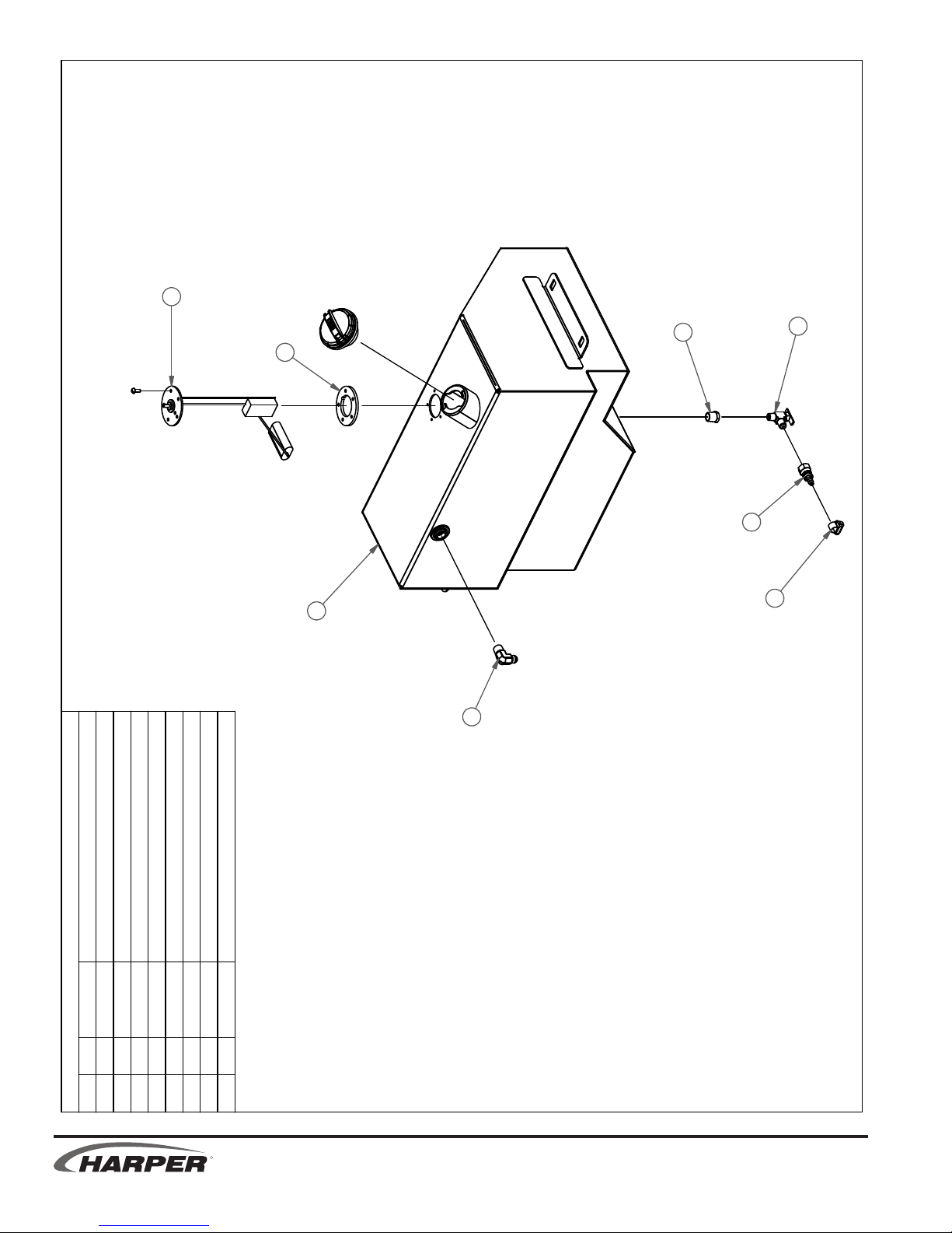
Page 32
12/5/2011
4
FUEL TANK ASSEMBLY
6
5
3
2
8
1
7
DESCRIPTION
ADAPTER, 5HB-6FBX12037811
ADAPTER, 6MJ-6MP9012050012
TANK - FUEL, WELDMENT
PARTS LIST
PART #
QTY
ITEM
SENDER - FUEL LEVEL, ELECTRIC
31514113
33200514
CLAMP, HOSE #10 .50"5200981
GASKET, FUEL SENDER5001721
FITTING, REDUCER 3/8 X 1/4 NPT
VALVE, FUEL SHUT OFF 6MB-4MP
50020916
80202318
7
5
R
1.6 1.7
TV 30
Page 33
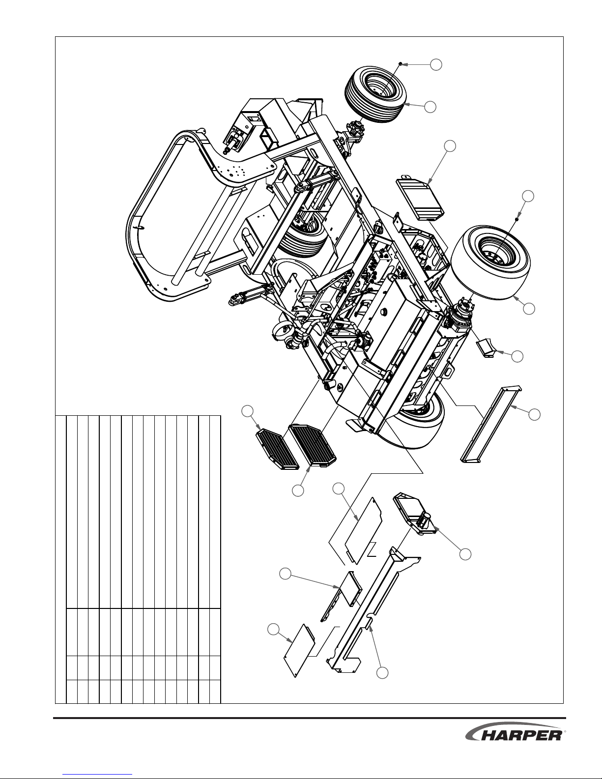
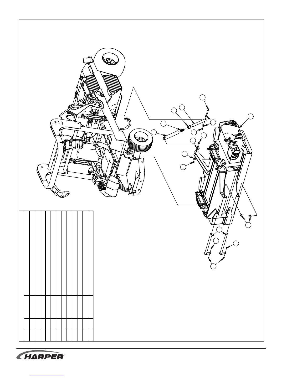
ENGINE SHIELD ASSEMBLIES
1
7/18/2011
3
9
1
2
4
8
7
DESCRIPTION
NUT - LUG 1/2-20
COVER - WHEEL MOTOR
LID - ENGINE ENCLOSURE3115651
26" MULTI-TRACK TIRE & WHEEL
PARTS LIST
PART #
QTY
ITEM
10x20 TIRE & WHEEL ASSEM - FRONT 30201123
110617201
30200822
SCREEN - DIESEL EXHAUST
31156124
31519016
5
SCREEN - INTAKE, WELDMENT31520719
PANEL - RADIATOR EXHAUST, WELDMENT3152051
7
ENCLOSURE - REAR ENGINE, WELDMENT
GUARD - UPPER RADIATOR, LOUVERED, WELDMENT
31520618
315208110
SCREEN - REAR INLET315223113
LID - ENGINE ENCLOSURE, WELDMENT315215111
ENCLOSURE - UPPER ENGINE, WELDMENT
315217112
12
11
5
6
10
13
TV 30
R
1.7
Page 34
PARTS LIST
DESCRIPTIONPART #QTYITEM
Bolt, 5/16-18 X 0.75 in Carriage11002081
NUT, 5/8-11 JAM11003922
BOLT, 3/8-16 X .75 FLT HD SKT HD
11012643
Bolt, 1/4-20 X 0.75 in Carriage110154234
NUT, 1/4-20 WIZ FLANGE110290235
Bolt, 1/4-20 X 0.625 in Carriage110358126
BOLT, 5/16-18 X 0.75, WIZ FLANGE11044467
BOLT, 3/8-16 X 4.5 TAP
11058128
NUT, 5/16-18 WIZ FLANGE110606149
WASHER, 3/8" LOCK
110672410
NUT, 3/8-16 GR 51108261011
Bolt, 5/16-18 X 1 in Carriage110871412
Bolt, 5/8-11 X 3 in Carriage110895113
SKIRT - DECK, RUBBER, FRONT302018114
SKIRT - DECK, RUBBER, SIDE
302034215
SCRAPPER - DECK ROLLER, RUBBER302049116
RETAINER - DECK SKIRT311335217
SPACER - IDLER311370118
BAFFLE - DECK, RETURN AIR311382319
RETAINER - DECK SKIRT, FRONT
311383120
BRACKET - ROLLER ADJUSTMENT, DECK311389221
BRACKET - ROLLER ADJUSTMENT, BEARING
311391222
BRACKET - ROLLER ADJUSTMENT, DECK311505123
RETAINER - SCRAPPER, DECK ROLLER311528124
CANVAS RING - EDGE GUARD, 5/32311587125
DECK WELDMENT315100126
LINKAGE - DECK MOUNT, UPPER, WELDMENT
315108127
LIFT - DECK, REAR, WELDMENT315112128
PIN - DECK, LOWER, WELDMENT315160229
PIN - DECK, WELDMENT315161430
MOUNT - SCRAPPER, DECK ROLLER, WELDMENT315177131
LINKAGE - DECK MOUNT, LOWER, WELDMENT
315193132
ROLLER - TV30 DECK, WELDMENT315197133
BEARING - 1", 2 - BOLT FLNG, MED DUTY342008234
BUSHING, MFI-1620-248001241035
DECK ASSEMBLY
12/2/2011
R
TV 30
1.8 ii 1.8
Page 35
12/2/2011
26
SEE HYDRAULIC
SECTION
35
35
27
DECK ASSEMBLY
35
28
35
30
33
9
9
6
25
1
13
18
2
3
15
21
5
19
22
8
34
11
12
10
11
TV 30
7
9
17
29
SECTION
35
4
SEE HYDRAULIC
32
35
35
29
20
14
R
ii 1.8
Page 36
12/2/2011
1
9
12
8
6
5
DECK INSTALLATION
DESCRIPTION
BOLT, 1/2-13 X 4.0
10
4
1
5
5
4
7
11
2
3
2
BUSHING, IGUS MFI-2024-24
10 1 315113 TUBE - LIFT LINK, WELDMENT
11 2 315162 PIN - DECK MOUNT, WELDMENT
12 1 800129
PARTS LIST
PART #
QTY
ITEM
NUT, 1/2-13, UNITORQUE LOCK
BOLT, 5/16-18 X 0.75, WIZ FLANGE
110658 WASHER, 1/2" FLAT STANDARD
1 2 110003
2 2 110444
3 2 110606 NUT, 5/16-18 WIZ FLANGE
4 2 110615
54
TV30 - BUILD STATION No. 5 - DECK
SPRING - COMPRESSION, 1-3/16 OD X 2. L, K 800
2 110913 RETAINING RING, 1" EXIT E
6 1 110861
7
8 1 305045
9 1 311133 ROD - LIFT LINK
R
1.9
TV 30
Page 37
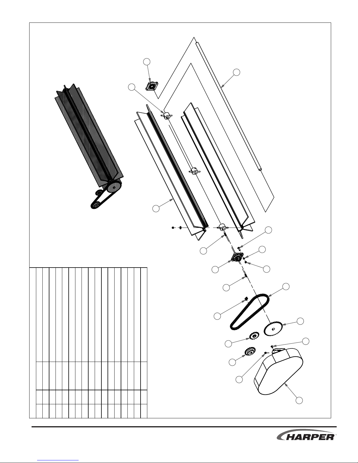
HARPER PRT No. 300044
KIT - ROTOR, BROOM, TV30D
12/2/2011
15
9
16
8
2
14
15
14
6
DESCRIPTION
Bolt, 3/8-16 X 1.25 in Carriage
Bolt, 5/16-18 X 0.75 in Carriage
Parts List
11040282
11002041
PART #
QTY
ITEM
NUT, 3/8-16 GR 51108261
WASHER, 3/8" LOCK
NUT, 5/16-18 WIZ FLANGE110606
11067284
4
5
3
BROOM, 60 in, TV30
SHAFT - BROOM, DECK31136919
CONNECTING LINK, #50 CHAIN
CHAIN - No 50 67 PIN W/O CONNECTOR1420061
30200318
14001116
7
SPROCKET - IDLER, 5017342007111
SHIELD - DECK BRUSH DRIVE, WELDMENT
315167110
KEY, 1/4 X 1/4 X 1.25 in
SPROCKET - 50B19 X 1
SPROCKET - 50B35 X 1342017113
342016112
FLANGE, 2 1/8 X 1, TJ-16973002316
BEARING - 1", 4 BLT FLNG
510089214
942093215
11
12
3
4
5
7
13
1
10
TV 30
R
1.10
Page 38
17
P
5
Y
)
0
7
T
8
0
0
.
.
4
7
(
0
.
2
1
12/2/2011
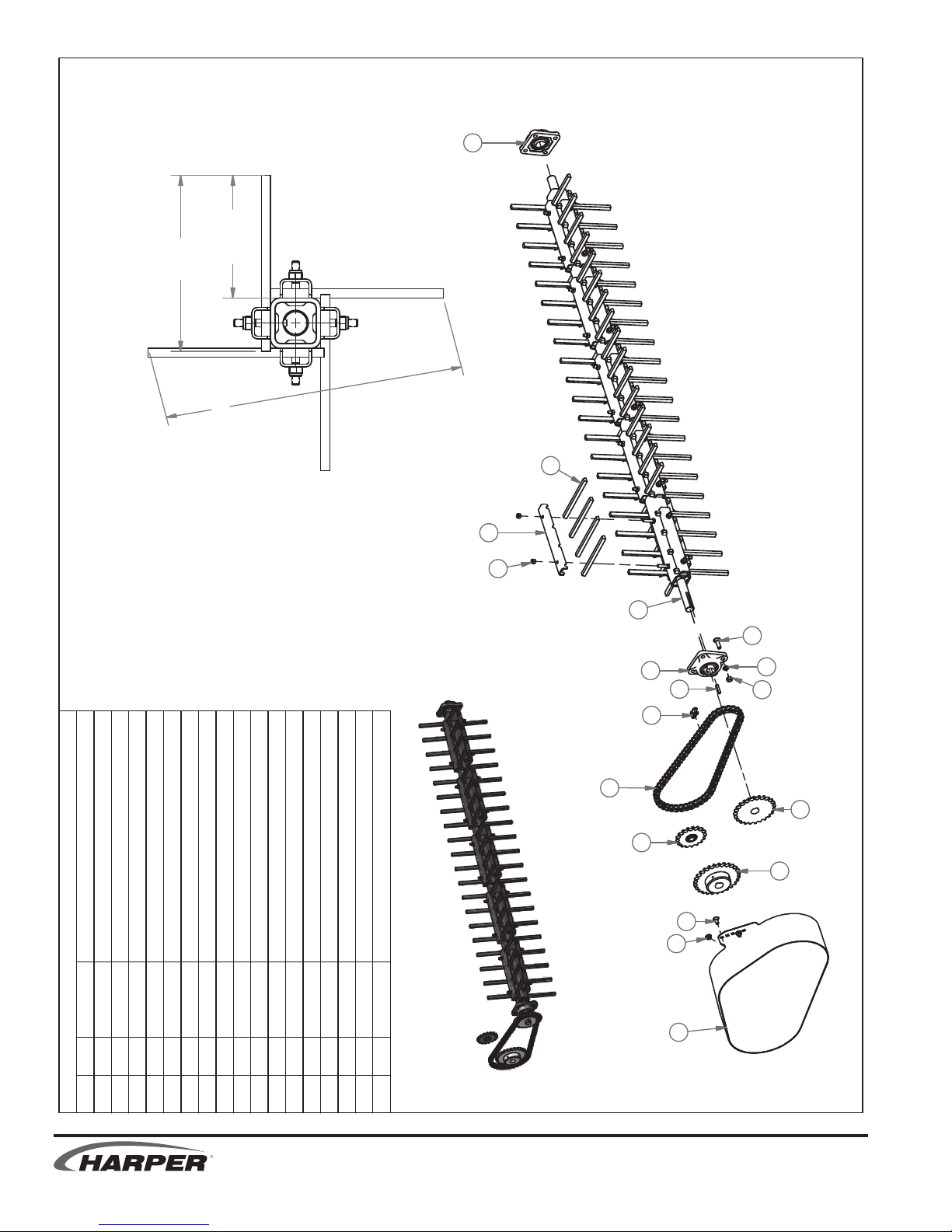
HARPER PRT No. 300040
10
KIT - ROTOR, FINGER, TV30D
DESCRIPTIONPART #QTYITEM
NUT, 5/16-18 LOCK (NYLON)
Bolt, 3/8-16 X 1.25 in Carriage11040282
Bolt, 5/16-18 X 0.75 in Carriage11002041
Parts List
NUT, 3/8-16 GR 511082686
WASHER, 3/8" LOCK11067285
NUT, 5/16-18 WIZ FLANGE11060644
FINGER - RUBBER302042809
CONNECTING LINK, #50 CHAIN14001117
CLAMP - RUBBER FINGER
CHAIN - No 50 67 PIN W/O CONNECTOR
SPROCKET - IDLER, 5017342007113
SHAFT - FINGER ROTOR, WELDMENT315179112
SHIELD - DECK BRUSH DRIVE, WELDMENT315167111
1/4" KEYSTOCK510089116
SPROCKET - 50B27 X 1342026114
SPROCKET - 50B24 X 1
BEARING - 1", 4 BLT FLNG942093217
3
9
12
2
17
16
7
8
13
1
4
5
6
15
14
110603403
14200618
3114032010
R
342030115
11
TV 30
1.11 1.12
Page 39

17
4
20
23
22
9
3
21
5
12/2/2011
HARPER PRT No. 300033
2
6
11
1
17
8
PARTS LIST
KIT - ROTOR, VERTICUT/DETHATCH, TV30D
DESCRIPTION
KEY, 3/8 X 3/8 X 1.75 in
PART #
7
16
6
15
31-2/1 ,TUN0160118
SetScrew, 3/8-16 X 0.75
Bolt, 1/2-13 X 1.75 in Carriage
WASHER, 1/2" LOCK
NUT, 5/16-18 WIZ FLANGE
SPROCKET - 60SF48
BUSHING - QD, SF, 1
SHIELD - DETHATCH ROTOR DRIVE
BEARING, 4FNG 1 1/2"
SPROCKET - IDLER, 6011
ROLLER CHAIN - No. 60, 74 PIN W/O CNCTR
WASHER - CUP, ROTOR
SPACER - VERTI CUTTER, 2 IN
12
14
19
13
18
6
10
QTY
1 1 100567
2 8 110042
ITEM
1 110332 COLLAR - 1-1/2" SPLIT
3 2 110107 NUT, 3/8-16 HEX JAM GR 2
6 7 110606
7
4 2 110325
5
9 1 311400 SHAFT - VERTICUTTER, TV30
8 8 110666
11 1 315195 GUARD - SHIELD SUPPORT, WELDMENT
10 1 315194
TV 30
21 29 970803
22 30 970804 DISC - DETHATCH, 10 Ga, 11 POINT
12 1 342022
15 1 342040
13 1 342023 SPROCKET - 60SK30
14 1 342024
18 1 942067 BUSHING, SK 1 1/2
16 1 410442 CONNECTING LINK, #60 CHAIN
19 1 942102
17 2 410851
20 1 970475 NUT - HEX, JAM, 1-3/4 - 5 UNC
23 1 970805
R
1.12
Page 40
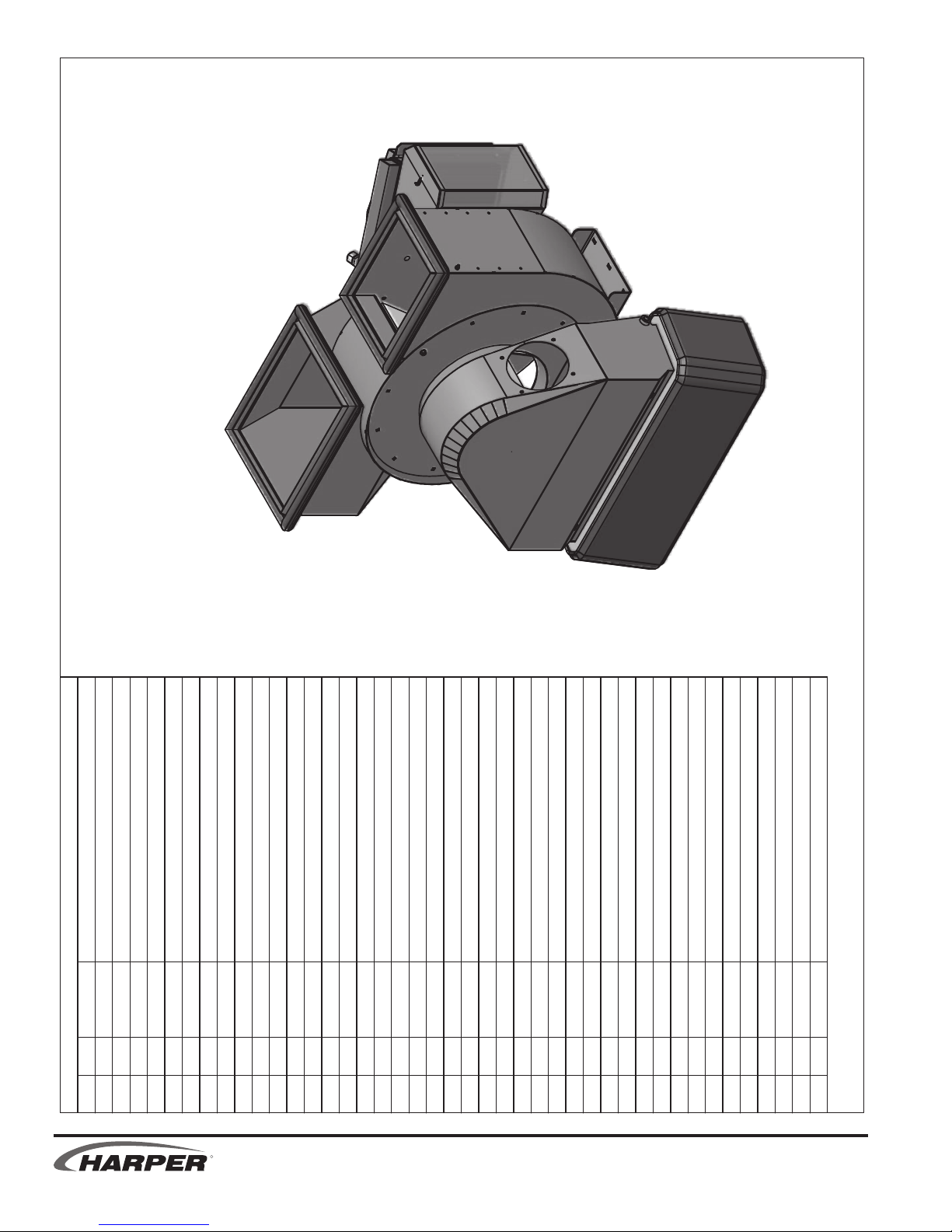
FAN HOUSING
7/15/2011
& HYDRAULIC COOLER ASSEMBLY
POP RIVET, 1/8
PARTS LIST
NUT, 1/2-13
BOLT, 1/4-20 X .75
PLUG - 11/16", NON-VENTED
RING - CANVAS, TV30
GASKET - FAN EXHAUST
CANVAS RING - EDGE GUARD, 5/32
FAN - HOUSING WELDMENT
FAN - 16", 12V, 20A, HYDRAULIC COOLER
1 17 110020 Bolt, 5/16-18 X 0.75 in Carriage
2 4 110042 Bolt, 1/2-13 X 1.75 in Carriage
3 4 110063
4 4 110093 SetScrew, 3/8-16 X 1.25
5 4 110290 NUT, 1/4-20 WIZ FLANGE
6 16 110326 Bolt, 1/4-20 X 1 in Carriage
7 4 110468 BOLT, 1/4-20 X 0.75, WIZ FLANGE
8 18 110561
9 21 110606 NUT, 5/16-18 WIZ FLANGE
10 4 110610
11 34 110630 NUT, 1/4-20 LOCK (NYLON INSERT)
12 12 110645 NUT, 3/8-16 WIZ FLANGE
ITEM QTY PART # DESCRIPTION
R
13 4 110666 WASHER, 1/2" LOCK
14 4 110826 NUT, 3/8-16 GR 5
15 2 110884
16 3 110890 PLUG - 1-1/4", FINISHING
17 12 110894 Bolt, 3/8-16 X 0.75 in Carriage
18 2 120515 ADAPTER - TUBING CONNECTOR, 1", 16MB
19 1 302001 LINER - FAN, TV30
20 1 302021
21 1 302022 GASKET - RETURN AIR
22 1 302023
23 1 311188 SHAFT - IMPELLER, TV30
24 4 311380 STRAP - HOLD DOWN, LINER
25 1 311493 SHROUD - COOLER FAN
26 1 311494 MOUNT - CORE, HYDRAULIC COOLER
27 1 311587
28 1 311588 AIR FUNNEL FLANGE SEAL - RUBBER, TRIMLOK
29 1 311589 HOPPER INLET SEAL - RUBBER, TRIMLOK
30 1 311590 RETURN AIR SEAL - RUBBER, TRIMLOK
31 1 315114 IMPELLER WELDMENT
32 1 315115
33 1 315122 FUNNEL - WELDMENT
34 1 315158 ADAPTER - FAN EXHAUST, WELDMENT
35 1 315159 ADAPTER - RETURN AIR, WELDMENT
36 1 315198 BREATHER - HYDRAULIC COOLER, WELDMENT
37 1 322028 COOLER - HYDRAULIC, TV30
38 1 332019 SWITCH - TEMP, HYDRAULIC OIL
39 1 333003
40 1 342009 BEARING, 4FNG 1 1/2", HD
41 2 810126 LATCH, FEMALE
42 1 940113 KEY, 3/8 X 5
TV 30
1.13
Page 41

39
1
5
25
7
18
23
10
13
34
20
17
2
30
9
40
18
37
38
1
9
1
36
3
41
26
11
32
7/15/2011
FAN HOUSING & HYDRAULIC COOLER ASSEMBLY
21
24
35
8
29
28
19
6
42
12
33
4
14
15
27
31
16
22
TV 30
R
ii 1.13
Page 42

4
FAN HOUSING INSTALLATION
10
2
20
SECTION
13
SEE HYDRAULIC
3
14
5
16
18
17
1
2
11
7
19
9
8
12
8
9
6
6
7/15/2011
15
3
BOLT, 7/16-14 X 1.25
NUT, 1/2-13
WASHER, 7/16" LOCK
COVER - ACCESS, FUNNEL
WASHER, 1/2" FLAT STANDARD
WASHER, 3/8" FLAT STANDARD
HUB, COUPLING 1-1/2" BORE
COVER - HOSE PORT, FUNNEL
PILLOW BLOCK BEARING, (1.5)
DESCRIPTION
BOLT, 1/2-13 X 1.75
KEY, 3/8 X 3/8 X 1.75 in
PARTS LIST
PART #
6 110612 NUT, 3/8-16 GR 2
QTY
1 1 100567
2 6 110419
ITEM
6 110556 Bolt, 3/8-16 X 1 in Carriage
3 8 110426 BOLT, 5/16-18 X 0.5, WIZ FLANGE
6 6 110610
7
4 2 110539
5
9 6 110666 WASHER, 1/2" LOCK
8 10 110658
R
11 6 110672 WASHER, 3/8" LOCK
12 6 110676
10 2 110671
13 1 305044 TV30 - BUILD STATION No. 4 - FAN HOUSING
15 1 311212
14 1 311211
18 1 922069 LOVEJOY COUPLER SPIDER
16 1 922067 COUPLING, 5/8" BORE
19 1 940103
17 1 922068
20 1 970291 ADAPTER PLATE
TV 30
1.14 1.15
Page 43

8
7/15/2011
OUTRIGGER INSTALLATION
6
9
DESCRIPTION
BOLT, 5/8-11 X 1.25
BOLT, 5/16-18 X 1, WIZ FLANGE
PARTS LIST
PIN - CYLINDER, OUTRIGGER
WASHER, 5/8" FLAT STANDARD
BUSHING, MFI-1620-24
OUTRIGGER - RH, WELDMENT
2
3
10
4
7
1
5
PART #
1 315119 OUTRIGGER - LH, WELDMENT
QTY
1 2 110026
2 2 110459
ITEM
2 110655 WASHER, 5/8" LOCK
3 2 110606 NUT, 5/16-18 WIZ FLANGE
6 2 311334
7
4 2 110650
5
9 2 315163 PIN - OUTRIGGER MOUNT, WELDMENT
8 1 315120
10 4 800124
TV 30
R
1.15
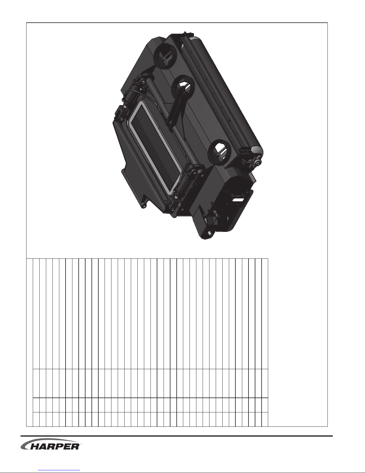
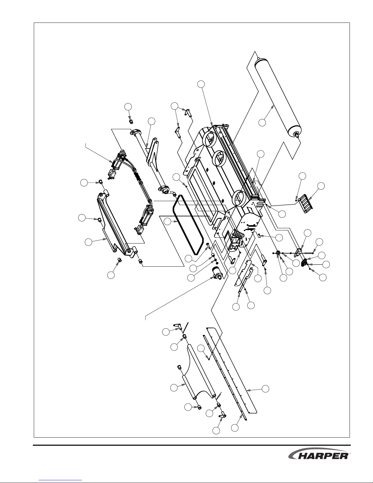
Page 44

8/10/2011
DOUBLE COVERPLATE
PARTS LIST
PARTS LIST
ITEM QTY PART # DESCRIPTION
LATCH HOUSING - LH, WELDMENT
PIN - CYLINDER, 3/4 IN, WELDMENT
HOPPER AND DOOR ASSEMBLY
2 810278 PLASTIC BUMPER, MOTOR GUARD
45 1 315145 CROSS TUBE - DOOR, WELDMENT
46 1 315146 LIFT LINK - WELDMENT
47 1 315147
48 1 315148 LATCH HOUSING - RH, WELDMENT
49 1 315149 LATCH - LH, WELDMENT
50 1 315150 LATCH - RH, WELDMENT
51 2 315151 LINK - LATCH, WELDMENT
52 3 315152
53 1 315153 PIN - CYLINDER, 1 IN, WELDMENT
54 1 522105
55
BOLT, 5/8-11 X 2.0
NUT, 1/4-20 WIZ FLANGE
BOLT, 5/16-18 X 0.75, WIZ FLANGE
NUT, 5/16-18 WIZ FLANGE
WASHER, 5/8" FLAT STANDARD
WASHER, 5/16" FLAT STANDARD
SPRING - COMPRESSION, 5/8 X 3.0
DEFLECTOR - DEBRIS, HOPPER, WELDMENT
CROSS TUBE - PIVOT, WELDMENT
1 53 110020 Bolt, 5/16-18 X 0.75 in Carriage
2 3 110155 WASHER, 3/8" FLAT SAE
3 17 110290
4 4 110298 WASHER, 1/4" FLAT SAE
5 4 110328 BOLT, 5/16-18 X 1 FLT HD SKT
6 1 110354 BOLT, 1/4-20 X 2.0 HEX HEAD
7 2 110358 Bolt, 1/4-20 X 0.625 in Carriage
8 2 110382
9 6 110440 BOLT, 3/8-16 X 1, WIZ FLANGE
10 4 110444
11 1 110494 BOLT, 3/8-16 X 3.25
12 3 110538 BOLT, 5/16-18 X 3.0
ITEM QTY PART # DESCRIPTION
R
13 2 110540 BOLT, 3/8-16 X 4.5
14 7 110603 NUT, 5/16-18 LOCK (NYLON)
15 49 110606
16 8 110616 NUT, 5/16", J-TYPE, CAGE, .5C
110766 SCREW, 1/4-20 X 1.0, FLAT HEAD TORX
4
17 4 110618 NUT, 3/8-16 LOCK NYLON INSERT
18 8 110630 NUT, 1/4-20 LOCK (NYLON INSERT)
19 2 110639 NUT, 5/8-11, UNITORQUE LOCK
20 4 110650
21 2 110656 WASHER, 3/8" FLAT SPECIAL
22 14 110665
23 1 110673 WASHER, 1/4" FLAT STANDARD
24 2 110676 WASHER, 3/8" FLAT STANDARD
25
26 4 110804 NUT, 3/8-16 U-TYPE .75L
27 2 110887
28 4 110897 JamHexNut 3_8-24 UNF
29 4 110984 SCREW, 1/4-20 X 1.25 FLAT HEAD TORX
30 1 122003 DOUBLE HOSE CLAMP
31 2 200029 COTTER PIN, 5/32 X 1
32 1 311248 BAFFLE - RETURN AIR, TV30
33 2 311285 MOUNT - LINKAGE, LATCH
34 1 311286 SKIRT - HOPPER, FRONT
35 1 311287 SKIRT - HOPPER, LH
36 1 311288 SKIRT - HOPPER, RH
37 1 311510 SHIM - TV30 DOOR LATCH
38 1 315125 HOPPER WELDMENT
39 1 315131
40 1 315132 SCREEN -PRIMARY, WELDMENT
41 1 315133 SCREEN -SECONDARY, WELDMENT
42 1 315134 DOOR - TV30, WELDMENT
43 1 315143 CROSS TUBE - HOPPER, WELDMENT
44 1 315144
TV 30
1.16
Page 45

14
22
45
50
48
8/11/2011
SEE HYDRAULIC
SECTION
17
21
53
52
8
20
43
1
6
54
9
22
22
14
52
22
44
12
21
11
30
1
51
12
46
52
2212
2
31
8
20
20
19
18
23
19
20
37
51
18
42
1
17
24
29
A
HOPPER AND DOOR ASSEMBLY
32
TV 30
26
41
1
16
26
10
40
16
5
39
15
36
34
7
38
35
1
3
55
25
18
28
33
51
27
49
15
2
47
31
4
2
DETAIL A
13
R
ii 1.16
Page 46

1
9
11
17
3
4
16
8
10
15
7/15/2011
2
5
7
13
HOPPER INSTALLATION
DESCRIPTION
BOLT, 5/16-18 X 1-1/2
NUT, 5/16-18 LOCK (NYLON)
BOLT, 5/16-18 X 0.75, WIZ FLANGE
PARTS LIST
6
14
FNU 61-4_3 tuNxeHmaJ29801128
NUT, 3/8-16 WIZ FLANGE
HOPPER ASSEMBLY
PIN - DECK, LOWER, WELDMENT
LIFT ARM - HOPPER, UPPER, WELDMENT
BRACE - LIFT ARM, HOPPER, WELDMENT
STOP - HOPPER LIFT CLINDER, WELDMENT
7
PART #
8 110606 NUT, 5/16-18 WIZ FLANGE
QTY
3 16 110556 Bolt, 3/8-16 X 1 in Carriage
1 2 110377
ITEM
4 2 110603
2 8 110444
16 110851 BUSHING - IGUS, 1-1/4 x 1 x 3/4 fng (RFI-1620-12)
6 16 110645
7
5
9 2 140016 PIN, LOCK, 1/4 X 2-1/4, SQ WIRE
11 2 315154 LIFT ARM - HOPPER, LOWER, WELDMENT
12 1 315155
10 1 314002
R
13 2 315156 END - LIFT ARM, HOPPER, WELDMENT
15 8 315160
14 1 315157
16 1 315176 LIFT ARM - HOPPER, UPPER, RH, WELDMENT
17 2 315196
TV 30
1.17
Page 47

17
25
7/18/2011
5
4
7
23
9
20
15
22
10
11
16
OPERATOR STATION
13
8
18
27
28
19
2
3
26
14
21
6
12
1
24
DESCRIPTION
Bolt, 5/8-11 X 2 in Carriage
Bolt, 3/8-16 X 1.25 in Carriage
PART LIST
PART #
QTY
3 2 110422 BOLT, 5/16-18 X .75
1 4 110391
2 4 110402
ITEM
BOLT, 5/16-18 X 0.75, WIZ FLANGE
4 4 110444
NUT, 5/16-18 LOCK (NYLON)
4 110606 NUT, 5/16-18 WIZ FLANGE
3 110468 BOLT, 1/4-20 X 0.75, WIZ FLANGE
6 4 110603
7
5
NUT, 5/8-11, UNITORQUE LOCK
NUT, 3/8-16 LOCK NYLON INSERT
9 3 110630 NUT, 1/4-20 LOCK (NYLON INSERT)
8 4 110618
11 4 110650 WASHER, 5/8" FLAT STANDARD
10 4 110639
TV 30
SEAT
WASHER, 5/16" LOCK
WASHER, 5/16" FLAT STANDARD
12 4 110665
13 4 110672 WASHER, 3/8" LOCK
14 2 110674
HOLDER, MANUAL
BOOT - STEERING, TV30
BOLT, 10-24 X .375 STAINLESS, PHILLIPS
211747 FRICTION WASHER 1.5"
110850 ISOLATOR - BUMPER, 64865K1, 250 LB
4
4
15 3 110788
18
16
19 1 302002
17 1 152004
20 1 302015 HOLDER - CUP, MOLDED
SHIELD - ROPS, TV30
21 1 302016
22 1 311129 CAP - END, STEERING BOX
23 1 311195
24 1 311372 BUMPER - TV30
MIRROR
STEERING WHEEL
BASE -MIRROR, LH, WELDMENT
26 1 315174 BASE -MIRROR, RH, WELDMENT
27 2 502027
25 1 315173
28 1 550004
R
1.18
Page 48

R
TV 30
Page 49

PARTS
HYDRAULIC
SECTION
TV 30
R
Page 50
12/2/2011
823004 Service Parts
O-RING, SQUARE FOR CAP
PART DESCRIPTION
802041
15
1
CAP, FILTER
GUAGE, OIL FILTER
852004
822002 FILTER REPLACEMENT
822017
822018 FILTER BREATHER
14
3
2
4
12
10
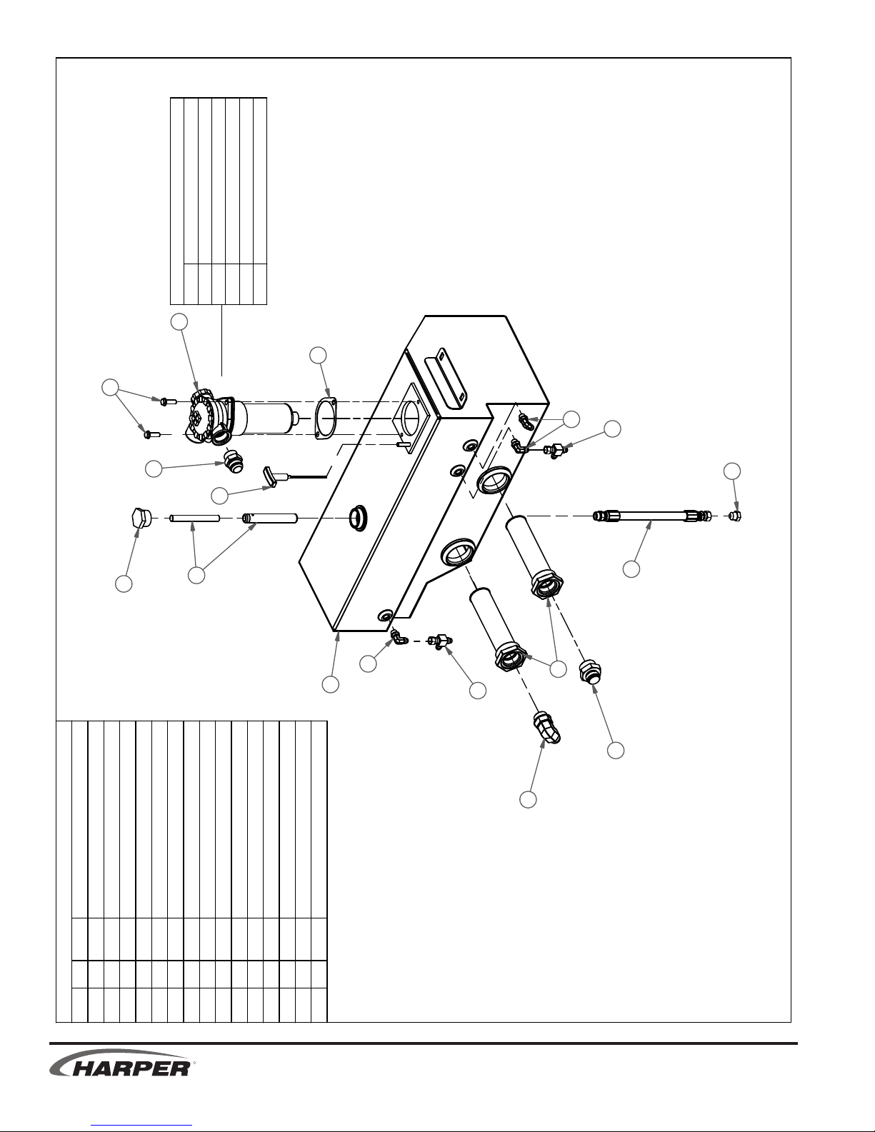
HYDRAULIC RESERVOIR ASSEMBLY
DESCRIPTION
ADAPTER, 6MJ-6MB9012022233
ADAPTER, 16MJ-16MB12035514
ADAPTER, 6MJ-6FJX-6MJ12021622
BOLT, 3/8-16 X 1.25, WIZ FLANGE
PARTS LIST
13
3
8
PLUG - 8-MJ
ADAPTER, 16MJ-20MB1203611
ADAPTER, 12MJ-20MB901205801
PLUG - TANK CLEANER
HOSE - RESERVOIR DRAIN32026419
TANK - HYDRAULIC, TV30, WLDMNT
STRAINER - SUCTION, SAE-20/-16322012211
DIP STICK - TV30, HYDRAULIC TANK
FILTER ASSY W/ELEMENT
GASKET - RETURN OIL FILTER
CLEANER - HYDRAULIC OIL, MGNTC323006113
2
11
7
9
5
6
11016121
PART #
QTY
ITEM
5
31514218
12054916
7
R
322010110
322025112
822029114
823004115
TV 30
2.1 2.2
Page 51
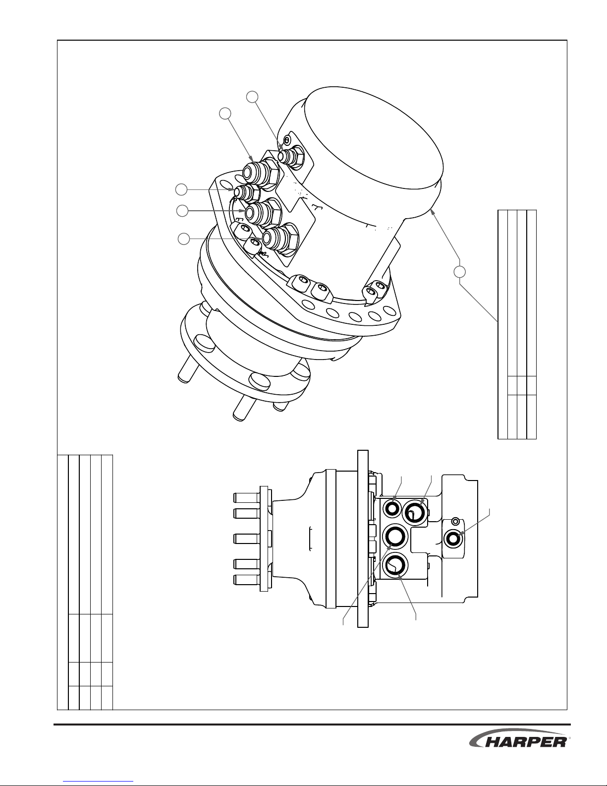
2
1
2
1
1
3
DISCRIPTION
7/28/2011
WHEEL MOTOR ASSEMBLY
CD
A1
322004 Service Parts
WHEEL MOTOR, NUT - LUG 1/2-20
WHEEL MOTOR, STUD
QTY
PART #
110607 6
322058 6
BR
DESCRIPTION
ADAPTER, 6MJ-6MB12031922
ADAPTER, 10MJ-10MB12025131
Parts List
MOTOR - WHEEL, HYDRAULIC, POCLAIN32200413
R
A2
PART #
QTY
ITEM
TV 30
R
2.2
Page 52
7/28/2011
6
12
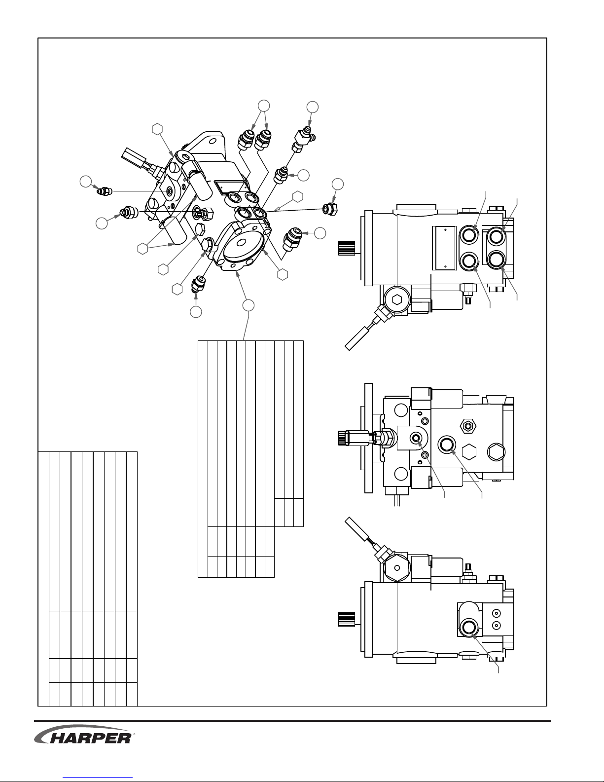
1
PROPULSION PUMP ASSEMBLY
2
3
9
8
10
3
7
3
8
11
5
4
PB
PA
OUTLET
CS
DESCRIPTION
ADAPTER, 4MJ-4MB1202331 2
ADAPTER, 6MJ-8MB1202393 3
ADAPTER, 12MJ-8MB1202501 4
ADAPTER, 6MJ-6FJX-6MJ1202161 1
Parts List
PART #
QTY
1
345
2
ITEM
ADAPTER, 10MJ-8MB1204932 6
PLUG, O-RING -8, EXTERNAL HEX120372
PUMP, PROPULSION 1.35/.43 CHRG ELEC3230011
4 5
7
6
R
323001 Service Parts
VALVE, IMPLEMENT PRESSURE RELIEF
VALVE, PROPULSION PRESS RELIEF
SOLONOID, PROPULSION PUMP
822021 PROPULSION PUMP SEAL KIT
-
8 822038
9 322044
ITEM PART # DESCRIPTION
10 322045
SEAL KIT, CA HOUSING, PAPER
SEAL KIT, CA HOUSING, O-RING
HOUSING, CA PROPULSION PUMP O-RING
822039
CP
822042
822034
VALVE, CHARGE PRESSURE RELIEF
ELECTRICAL PROPULSION PUMP CONTROLER
322046
333001
11
12
CD
CR
TV 30
2.3 2.4
Page 53
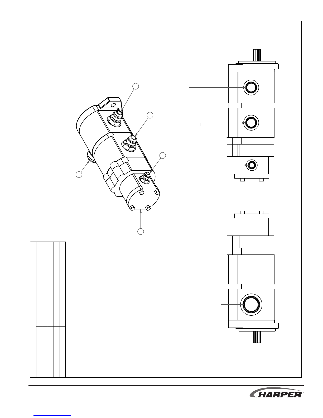
8/1/2011
2
2
3
4
FRONT (DECK) SECTION OUTLET
TRIPLE SECTION PUMP ASSEMBLY
MIDDLE (FAN) SECTION OUTLET
1
SMALL END (IMPLEMENT) SECTION OUTLET
DESCRIPTION
Parts List
PART #
ADAPTER, 6MJ-6MB12031913
ADAPTER, 10MJ-10MB12025122
PUMP - HYDRAULIC, 3 SEC
32300211
ADAPTER, 16MJ-16MB12035514
SUCTION INLET
QTY
ITEM
TV 30
R
2.4
Page 54
5
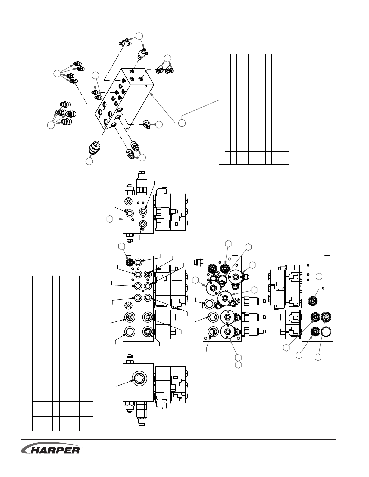
MASTER VALVE ASSEMBLY
2
6
4
3
1
7
4
8
323003 Service Parts
ITEM PART # DESCRIPTION
C'BALANCE VALVE
N.O. SOL VALVE
8.00 SEQ VALVE
322033 22.5 RELIEF VALVE12322034 27.0 RELIEF VALVE
820232
10 322032 25.0 RELIEF VALVE
11
13 322035
14
15 522163 VDC ER COIL
16 322038 3P 4W SOL VALVE
17 322039
18 322040 VALVE BODY
19 522160 PILOT CHECK VALVE
12/2/2011
LOE
DLE
18
13
BLR
BDE
ROE
BLR
LOR
BDR
16
P
17
19
16
10
16
DLE
DLR
PF
DESCRIPTIONPART #QTYITEM
PARTS LIST
ADAPTER, 4MJ-6MB12024923
ADAPTER, 6MJ-10MB12014411
ADAPTER, 6MJ-6MB9012022222
ADAPTER, 6MJ-6MB12031946
ADAPTER, 10MJ-10MB12025164
ADAPTER, 6MJ-6MB-6MJ12027925
VALVE BLOCK - TV30
ADAPTER, 16MJ-16MB12035517
32300318
FMR
FMP
DMR
DMP
DP
1415
11
12
13
T
1
342
869
R
2.5 2.6
TV 30
Page 55

3
8/15/2011
3
1
4
PROPULSION VALVE ASSEMBLY
LCD
BR1
LA1
1
2
5
4
LA2
11
9
6
7
DR
LR
CP
PA
8
10
PB
1314
12
DESCRIPTION
PARTS LIST
PART #
QTY
ITEM
ADAPTER, 6MJ-6MB12031933
ADAPTER, 10MJ-12MB12025332
ADAPTER, 6MJ-6MB 4512021931
Jic(-10) to Male O-ring (-12), 45 degrees
VALVE - CONTROL, PROPULSION, TV303230081
120410
5
5
4
323008 Service Parts
MANIFOLD BODY
6 322049
ITEM PART # DESCRIPTION
TV 30
RA2
DIVERTER VALVE, 100PSI SPRING
3POS 4WAY SOLENOID VALVE
RA1
RR
322057 CHECK VALVE 3PSI SPRING
11 322054 2POS 3WAY SOLENOID VALVE
8 322051
9 322052 12VDC DEUTSCH COIL
12 322055 CHECK VALVE
10 322053 12VDC DEUTSCH COIL S SERIES
7 322050
14
13 322056 REMOVABLE ORIFICE
RCD
BR2
R
2.6
Page 56
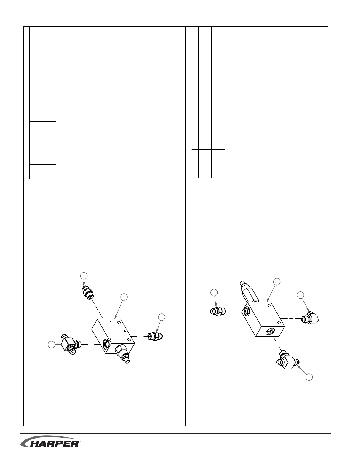
8/15/2011
PARTS LIST
DESCRIPTIONPART #QTY
ADAPTER, 6MJ-6MB12031922
ADAPTER, 6MJ-6MJ-6MB12009211
VALVE - SEQUENCE, PROPULSION, TV3032300713
ITEM
DESCRIPTIONPART #QTY
PARTS LIST
ITEM
ADAPTER, 6MJ-6MB12031913
ADAPTER, 6MJ-6MB9012022212
ADAPTER, 6MJ-6MJ-6MB12009211
VALVE - PRESSURE REDUCING
32301514
SEQUENCE VALVE ASSEMBLY
2
4
3
2
1
3
2
1
PRESSURE REDUCTION VALVE ASSEMBLY
R
2.7 2.8
TV 30
Page 57
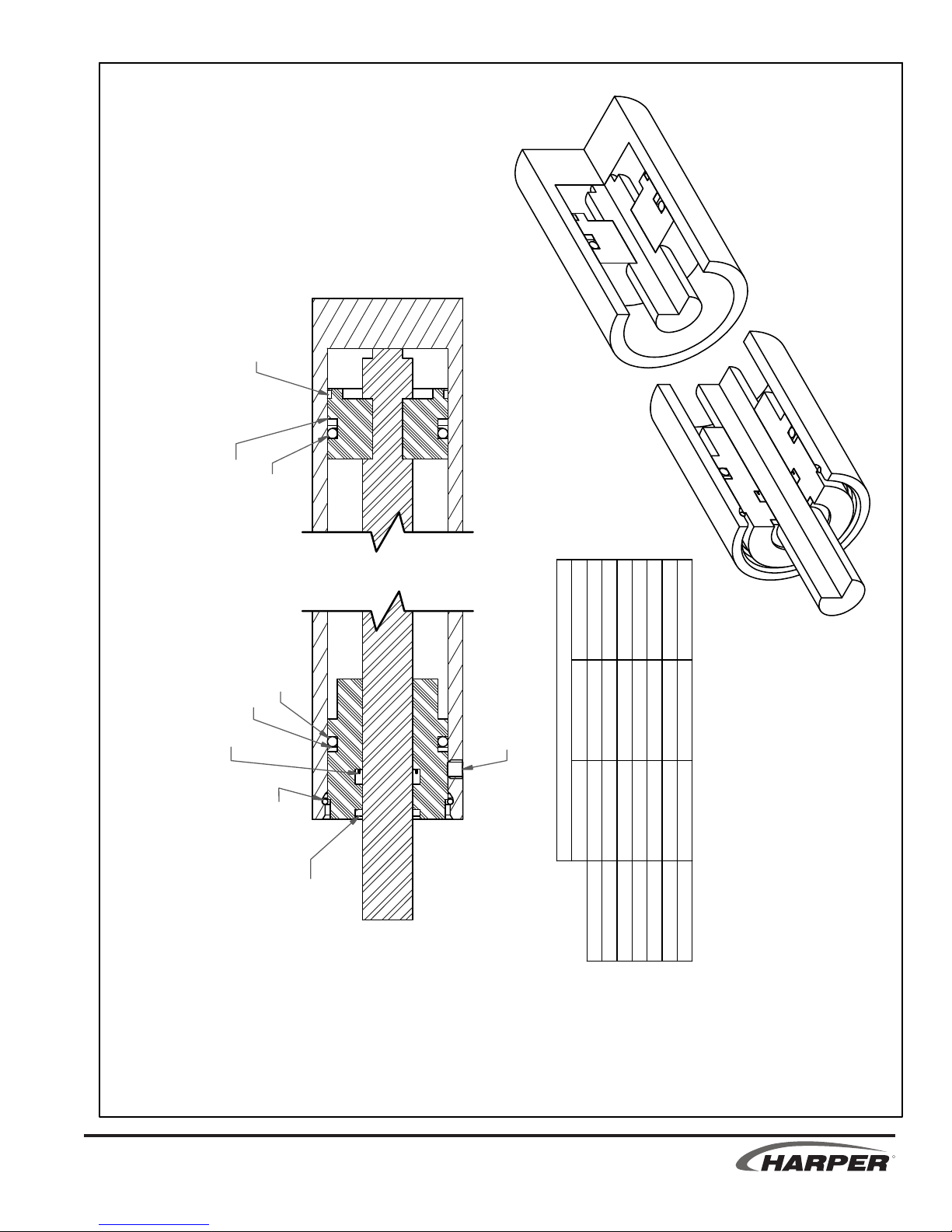
TEFLON RING
8/1/2011
WEAR RING
O-RING
HYDRAULIC CYLINDER SERVICE PARTS
BACK-UP
U-CUP
O-RING
RETAINING RING
-
-
Retaining Ring
SET-SCREW
WIPER
Seal Kit
Service Parts
323010 322047 322048
323032 220534 220092
323018 220387-323033 220387
Cylinder Part #
Steering
LH Deck Lift
323019 220387
323031 220534 220092
922021 922076 520459
Hopper Lift
RH Deck Lift
LH Outrigger
Hopper Door
RH Outrigger
TV 30
R
2.8
Page 58

7/7/2011
PROPULSION SYSTEM
R
TV 30
2.9
Page 59

TV 30
R
ii 2.9
Page 60

8/11/2011
PROPULSION PLUMBING
LA1
RBRLBR
LA2
LCD
LR
RR
RCD
RA1
RA2
VAVLE -
CONTROL
PROPULSION
CP
PA
VALVE
SEQUENCE
DESCRIPTIONPART #QTYITEM
ADAPTER, 6MJ-12MB1203642 1
HOSE - SEQUENCE VALVE INLET3202251 2
HOSE - SEQUENCE VALVE OUTLET
HOSE - PROPULSION "A" PRESSURE3202401 4
Parts List
HOSE - PROPULSION "B" PRESSURE3202411 5
HOSE - PRESSURE REDUCTION VALVE SUPPLY3202551 6
HOSE - PROPULSION VALVE CHG PRESSURE SUPLY3202561 7
FILTER - MID-PRESSURE
HOSE - PILOT CONTROL PRESSURE3202611 9
HOSE - PROPULSION VALVE CASE DRAIN
MID
PRESSURE
320260
320256
320225
FILTER
320226
320255
VALVE
PRESSURE
3202261 3
32300501 1
3202601 8
REDUCTION
PB
DR
320241
320240
PA
320261
PB
PUMP -
CR
CP
CD
PROPULSION
132
456
7
8
9
R
CS
TV 30
iii 2.9 iv 2.9
Page 61

6
8/11/2011
4
SEE PROPULSION
PUMP ASSEMBLY
5
SEE PRESSURE
9
7
3
REDUCTION VALVE
PROPULSION PLUMBING
TV 30
VALVE ASSEMBLY
8
SEE PROPULSION CONTROL
10
1
323005 Service Parts
SEE SEQUENCE
2
PART# DESCRIPTION DETAILS
322009 FILTER SEE MAINTENANCE SECTION
VALVE ASSEMBLY
R
iv 2.9
Page 62

LBR
LA2
RR
7/6/2011
WHEEL MOTOR PLUMBING
LA1
CD
WHEEL MOTOR
LR
320239
320233
320231
320230
LA2
LA1
RBR
320234
320232
LCD
LR
320236
320237
RA2
RR
RCD
RA1RA2
320235
RA1
VALVE -
CD
RBR
320238
CONTROL
WHEEL MOTOR
PROPULSION
CP
PA
PB
DR
DESCRIPTIONPART #QTYITEM
HOSE - LEFT WHEEL MOTOR RETURN
HOSE - LEFT WHEEL MOTOR A1 PRESSURE32023011
Parts List
HOSE - LEFT WHEEL MOTOR A2 PRESSURE32023112
HOSE - LEFT WHEEL MOTOR BRAKE RELEASE32023314
32023213
HOSE - RIGHT WHEEL MOTOR RETURN32023617
HOSE - LEFT WHEEL MOTOR CASE DRAIN32023415
HOSE - RIGHT WHEEL MOTOR A1 PRESSURE32023516
HOSE - RIGHT WHEEL MOTOR CASE DRAIN32023819
HOSE - RIGHT WHEEL MOTOR A2 PRESSURE
HOSE - RIGHT WHEEL MOTOR BRAKE RELEASE
32023718
320239110
R
2.10 ii 2.10
TV 30
Page 63

5
SEE WHEEL
MOTOR
ASSEMBLY
3
2
1
SEE PROPULSION
VALVE ASSEMBLY
7/6/2011
WHEEL MOTOR PLUMBING
4
7
10
8
6
9
TV 30
R
ii 2.10
Page 64

Parts List
DESCRIPTIONPART #QTYITEM
ADAPTER, 4MB-4MJ 4512002721
ADAPTER, 6MJ-6FJX-6MJ12021612
ADAPTER, 6MJ-12MB12036413
HOSE - STEERING, AUX OUTLET32021914
HOSE - STEERING OUTLET32022015
HOSE - STEERING INLET32022116
HOSE - STEERING CYL RETRACT32022217
HOSE - STEERING CYL EXTEND
32022318
CYLINDER - STEERING, 1-3/4 X 632301019
IN
AUX
OUT
LFT
RT
320221
320222
320223
320219
320220
STEERING SYSTEM
FROM PUMP -
PROPULSION
MID
PRESSURE
FILTER
CYLINDER -
STEERING
7/1/2011
R
2.11 ii 2.11
TV 30
Page 65
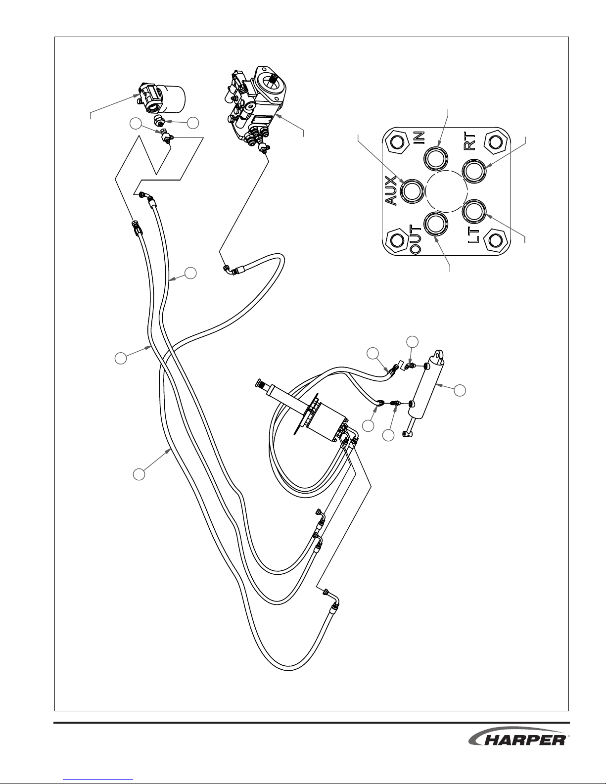
320221
IN
8/11/2011
2
SEE
PLUMBING
PROPULSION
3
PUMP ASSEMBLY
SEE PROPULSION
5
320219
AUX
320223
RT
LT
320222
OUT
320220
1
4
8
9
STEERING SYSTEM
7
1
6
TV 30
R
ii 2.11
Page 66

Parts List
DESCRIPTIONPART #QTYITEM
HOSE - PROPULSION SUCTION HOSE32022911
HOSE - PRESSURE REDUCTION VALVE DRAIN32025812
HOSE - SEQUENCE VALVE DRAIN32025913
HOSE - PROPULSION PUMP CASE DRAIN32026314
CP
CR
CS
CD
PA
PB
320263
320262
320258
320259
PROPULSION SUCTION & DRAIN PLUMBING
PUMP -
PROPULSION
VALVE -
SEQUENCE
VALVE -
PRESSURE
REDUCTION
TO TANK
TO TANK
TO TANK
12/5/2011
R
2.12 ii 2.12
TV 30
Page 67
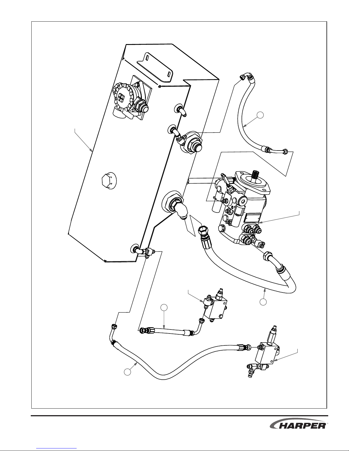
12/5/2011
4
TANK ASSEMBLY
SEE HYDRAULIC
PUMP ASSEMBLY
SEE PROPULSION
PROPULSION SUCTION & DRAIN PLUMBING
TV 30
VALVE ASSEMBLY
SEE SEQUENCE
3
2
1
ASSEMBLY
REDUCTION VALVE
SEE PRESSURE
R
ii 2.12
Page 68
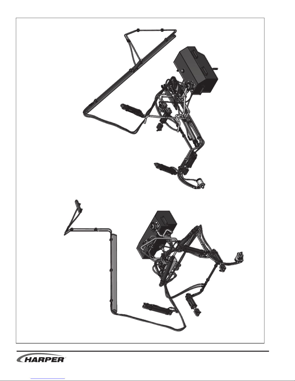
BACK LEFT
7/13/2011
MACHINE SYSTEM
FRONT LEFT
R
2.13 ii 2.13
TV 30
Page 69
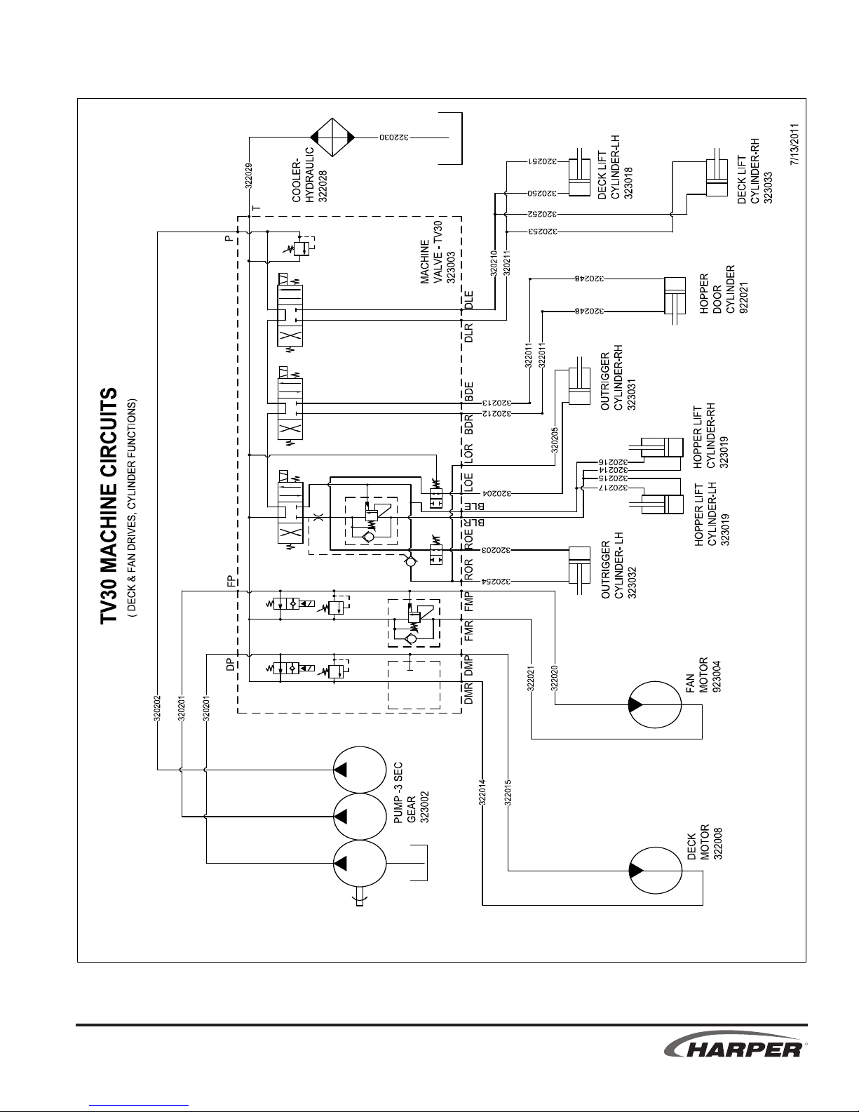
TV 30
R
ii 2.13
Page 70
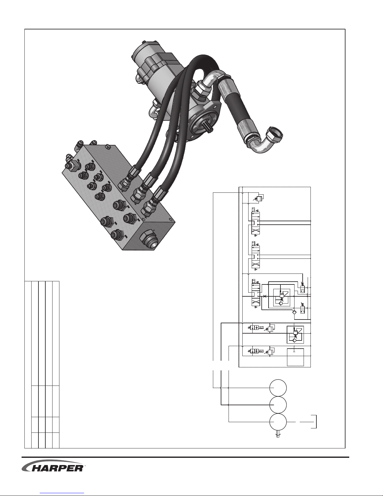
Parts List
DESCRIPTIONPART #QTYITEM
HOSE - DECK & FAN PRESSURE SUPLY32020121
HOSE - CYLINDER FCN'S SUPPLY32020212
HOSE ASSY, 1.0X14.25" 16FJX60M - 16FJX90M32205913
BDR
P
FP
T
DP
DMR DMP
FMR
FMP ROR ROE
B
LR
LOE
BLE
BDE
LOR DLR
DLE
320201
320201
320202
322059
TRIPLE SECTION (MACHINE) PUMP PLUMBING
12/2/2011
VALVE -
MACHINE
PUMP - 3
SEC GEAR
FROM
TANK
R
2.14 ii 2.14
TV 30
Page 71
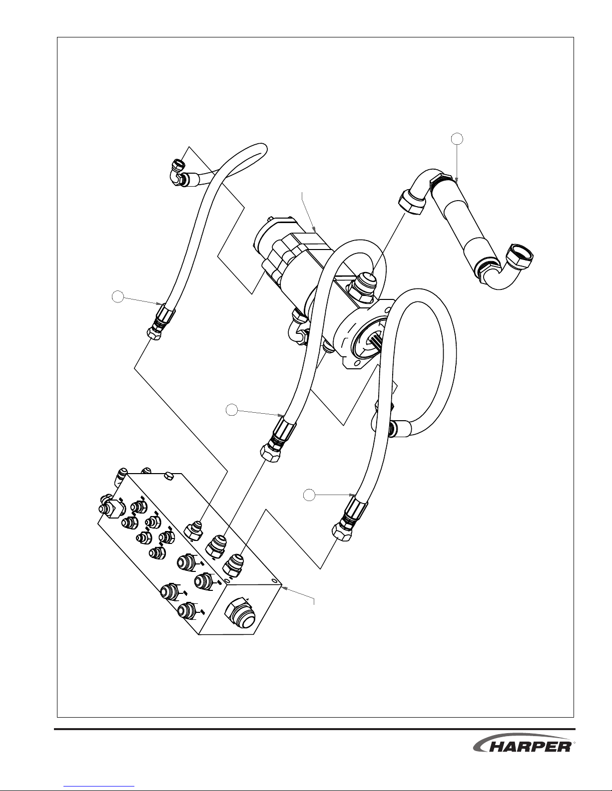
2
1
1
3
TRIPLE SECTION (MACHINE) PUMP PLUMBING
12/2/2011
SEE TRIPLE SECTION
PUMP ASSEMBLY
SEE MACHINE
VALVE ASSEMBLY
TV 30
ii 2.14
R
Page 72
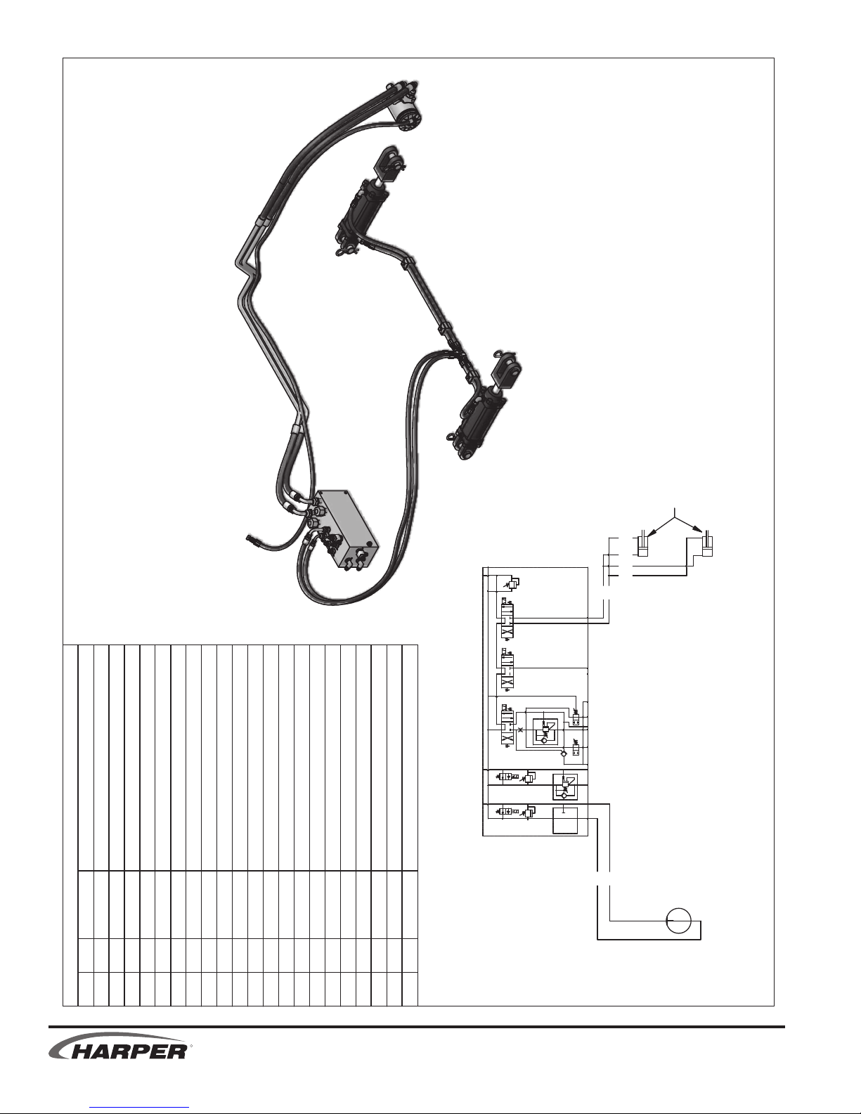
Parts List
ITEM QTY PART # DESCRIPTION
1 3 110430 BOLT, 1/4-20 X 1-1/4
2 3 110667 WASHER, 1/4" LOCK
3 2 120219 ADAPTER, 6MJ-6MB 45
4 2 120222 ADAPTER, 6MJ-6MB90
5 1 120235 ADAPTER, 4MJ-4MB90
6 2 120241 ADAPTER, 4MJ-4MJ-4MJ
7 2 120251 ADAPTER, 10MJ-10MB
8 1 320210
HOSE - DECK LIFT EXTEND
9 1 320211 HOSE - DECK LIFT RETRACT
10 1 320247
HOSE - DECK MOTOR CASE DRAIN
11 1 320250 HOSE - DECK, LEFT REAR
12 1 320251 HOSE - DECK, LEFT FRONT
13 1 320252 HOSE - DECK, RIGHT REAR
14 1 320253 HOSE - DECK, RIGHT FRONT
15 1 322008
MOTOR, 4.9 CID, 1" SHFT
16 1 322014 HOSE - DECK DRIVE, LOWER ASSEMBLY
17 1 322015 HOSE - DECK DRIVE, UPPER ASSEMBLY
18 1 323018 CYLINDER - 2 x 4, SAE-6, TIE ROD
19 1 323033 CYLINDER - 2 X 4, SAE-6, TIE ROD
20 3 522104
DOUBLE HOSE CLAMP
21 3 522105 DOUBLE COVERPLATE
P
FP
T
DP
DMR DMP FMR FMP ROR ROE
BLR
LOE
BLE
BDELOR BDR DLR DLE
322014
322015
320210
320211
320250
320251
3
20252
320253
7/11/2011
DECK PLUMBING
VALVE -
MACHINE
CYLINDERS -
DECK LIFT
MOTOR -
DECK
R
TV 30
2.15 ii 2.15
Page 73
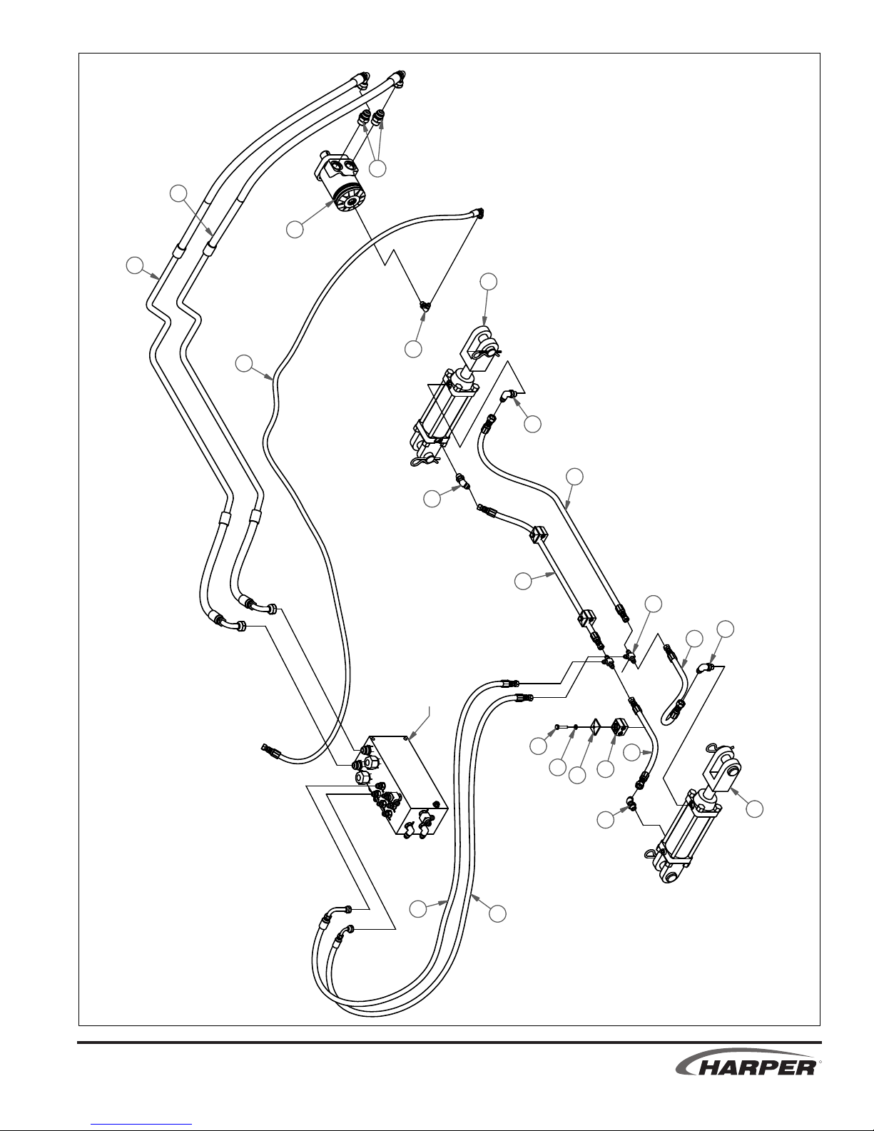
7/11/2011
7
16
15
17
18
5
10
4
12
3
DECK PLUMBING
SEE MACHINE
8
11
6
4
14
VALVE ASSEMBLY
1
2
21
9
20
13
3
19
TV 30
R
ii 2.15
Page 74

Parts List
DESCRIPTIONPART #QTYITEM
ADAPTER, 6MJ-6MB9012022211
ADAPTER, 10MJ-12MB12025322
HOSE ASSY, FAN RETURN32020713
HOSE ASSY, FAN PRESSURE32020814
HOSE - FAN MOTOR CASE DRAIN3202461
5
MOTOR, 1.71 CI, FAN DRIVE92300416
FAN MOTOR
923004
MACHINE
VALVE
P
FP
DP
DMR DMP FMR FMP ROR ROE
BLR
LOE
BLE
BDE
LOR BDR DLR DLE
320207
320208
320246
TO TANK
T
FAN MOTOR PLUMBING
12/1/2011
R
TV 30
2.16 ii 2.16
Page 75

7/12/2011
SEE MACHINE
VALVE ASSEMBLY
4
TO TANK
2
3
FAN MOTOR PLUMBING
TV 30
1
5
6
2
R
ii 2.16
Page 76

OUTRIGGER PLUMBING
7/12/2011
T
P
CYLINDER - 2 X 12, SAE -6
Parts List
HOSE - LH OUTRIGGER RETRACT
FP
DP
VALVE -
MACHINE
DLR DLE
BDE
BDR
LOR
LOE
BLE
LR
B
4
ROR ROE
FMR FMP
DMR DMP
320205
0204
32
320203
2025
3
OUTRIGGER
CYLINDER - RH
OUTRIGGER
CYLINDER - LH
1 1 120222 ADAPTER, 6MJ-6MB90
2 3 120319 ADAPTER, 6MJ-6MB
3 1 320203
4 1 320204 HOSE - RH OUTRIGGER EXTEND
5 1 320205 HOSE - RH OUTRIGGER RETRACT
6 1 320254 HOSE - LH OUTRIGGER RETRACT
7 1 323031 CYLINDER - 2 X 12, SAE-6
ITEM QTY PART # DESCRIPTION
8 1 323032
R
2.17 ii 2.17
TV 30
Page 77

5
7
2
SEE MACHINE
VALVE ASSEMBLY
2
7/12/2011
6
OUTRIGGER PLUMBING
8
1
2
4
3
TV 30
R
ii 2.17
Page 78

HOPPER PLUMBING
7/13/2011
T
P
VALVE -
MACHINE
CYLINDER -
320248
48
202
3
322011
322011
320213
BDE
320212
BDR DLR DLE
LOR
LOE
BLE
BLR
HOSE - HOPPER DOOR, TOP
Parts List
ADAPTER - VELOCITY, 2 GPM, 6MP-6MJ
HOSE - RH CYL HOPPER LIFT RETRACT
FP
DP
ROR ROE
FMR FMP
HOPPER DOOR
320216
320214
320215
320217
CYLINDERS -
HOPPER LIFT
1 2 120179 ADAPTER, 6MJ-4MB90
2 9 120222 ADAPTER, 6MJ-6MB90
3 2 120538
4 1 320212 HOSE - HOPPER DOOR EXTEND
5 1 320213 HOSE - HOPPER DOOR RETRACT
6 1 320214 HOSE - RH CYL HOPPER LIFT EXTEND
7 1 320215 HOSE - LH CYL HOPER LIFT EXTEND
8 1 320216
9 1 320217 HOSE - LH CYL HOPPER LIFT RETRACT
10 1 320248
11 2 322011 HOSE - TV30 HOPPER DOOR, ASSEM
ITEM QTY PART # DESCRIPTION
R
12 2 323019 CYLINDER - 2 X 8, SAE-6
DMR DMP
13 1 922021 HYDRAULIC CYLINDER
TV 30
2.18 ii 2.18
Page 79

11
11
10
10
1
1
13
5
4
7
3
9
2
12
6
3
8
2
12
SEE MACHINE
VALVE ASSEMBLY
HOPPER PLUMBING
7/13/2011
TV 30
R
ii 2.18
Page 80

PORT LABEL ABBREVIATIONS
ABBREVIATION DESCRIPTION
AUX AUXILIARY
BDE
BDR
BLE
BLR
BOX/HOPPER DOOR EXTEND (CLOSE)
BOX/HOPPER DOOR RETRACT (OPEN)
BOX/HOPPER LIFT EXTEND (UP)
BOX/HOPPER LIFT RETRACT (DOWN)
CD CASE DRAIN
CP CHARGE PRESSURE
CR CHARGE RETURN
CS CASE SUCTION
DLE
DLR
DECK LIFT EXTEND (DOWN)
DECK LIFT RETRACT (UP)
DMP DECK MOTOR PRESSURE
DMR DECK MOTOR RETURN
DP DECK PRESSURE
DR DRAIN
FMP FAN MOTOR PRESSURE
FMR FAN MOTOR RETURN
FP FAN PRESSURE
IN INLET
LA1
LEFT A1 PRESURE
LA2 LEFT A2 PRESSURE
LBR LEFT BRAKE RELEASE
LCD LEFT CASE DRAIN
LFT
LOE
LOR
LR
LEFT TURN
LEFT OUTRIGGER EXTEND (OUT)
LEFT OUTRIGGER RETRACT (IN)
LEFT RETURN
OUT OUTLET
P
PRESSURE (IMPLEMENT)
PA PRESSURE A
PB
PRESSURE B
RA1 RIGHT A1 PRESSURE
RA2 RIGHT A2 PRESSURE
RBR RIGHT BRAKE RELEASE
RCD RIGHT CASE DRAIN
ROE
ROR
RIGHT OUTRIGGER EXTEND (OUT)
RIGHT OUTRIGGER RETRACT (IN)
RR RIGHT RETURN
RT RIGHT TURN
T TANK
R
2.19
TV 30
Page 81

PARTS
ELECTRICAL
SECTION
TV 30
R
Page 82
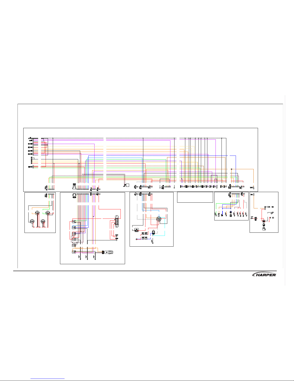
TV 30
R
3.1
TV30 DIESEL WIRING SCHEMATIC DIAGRAM OVERVIEW
HI / LO
SWITCH
332006
RELAY
HARNESS
332016
IGNITION
HARNESS
HYDRAULIC VALVES
332029
HYDRAULIC
COOLER FAN
HARNESS
FAN
SOLENOID
DOOR
SOLENOID
HOPPER
LIFT
SOLENOID
BRAKE
INDICATOR
LIGHT
2
3
7
FAN
SWITCH
YELLOW
BRAKE
SWITCH
1
2
3
HOPPER
DOOR
SWITCH
1
2
3
HOPPER
LIFT
SWITCH
BROOM
SWITCH
1
2
3
2
3
7
DEUTSCH DT SERIES
12 CAVITY SOCKET
1
2
3
DECK LIFT
SOLENOID
BROOM
SOLENOID
DECK LIFT
SWITCH
RED
INCLINOMETER
SWITCH
11X
DEUTSCH
DT SERIES
2 CAVITY
PLUG
5/16 RING
INS
BRAKE
RELEASE
SOLENOID
HI/LO
SHIFT
SOLENOID
1 2
1 2
5/16 RING
INS
TO
GRD
1 21 2
HYDROSTATIC
PUMP
YEL/GRN
YEL/BLU
WHT/ORG
ORANGE
ORG/BLU
PUR/GRN
YEL/BLK
WHITE
RED/WHT
RED/WHT
RED/WHT
RED/WHT
RED/WHT
RED/WHT
BLACK
BLACK
PUR/RED
PUR/RED
BLACK
RED
RED/WHT
BRN/GRN
GREEN
5/16 RING
INS
TO FOOT
PEDAL
SEAT
SWITCH
N/O
BLACK
PUR/YEL
1 2
3 4
5 6 7 8
*
*
PUR/YEL
BROWN
GREEN
GRN/WHT
WHT/BLK
WHT/BLK
BLUE
BLU/YEL
RED
YEL/BLK
WHT/BLK
BRN/BLK
PUR/GRN
YEL/GRN
YEL/BLU
ORANGE
ORG/BLU
GREEN
ORANGE
PUR/BLK
RED 10 Ga
REV
FRD
BROWN
YELLOW
WHITE
RED
WHT/ORG
RED/WHT
WHT/BLK
RED
GRN/WHT
WHT/BLK
PUR/BLK
BLU/YEL
BLUE
PUR/YEL
PUR/YEL
BROWN
BROWN
RED 10 Ga
1 21 2
1 2
1 21 2
1 2
1 221 1 21 2
5 6 7 8 9 10 1112
1 2 3
4
1 2
*
1 2 3
4
1 2
1 2 3
5 64
*
1 2
*
PACKARD 630
SERIES. 10 CAVITY
DEUTSCH
DT SERIES
4 CAVITY
PLUG
DEUTSCH DT SERIES
12 CAVITY PLUG
PUR/YEL
PUR/YEL
BROWN
BROWN
YELLOW
WHITE
RED
WHT/ORG
RED/WHT
WHT/BLK
RED/WHT
GRN/WHT
WHT/BLK
PUR/BLK
BLU/YEL
BLUE
1
2
1
2
2X
DEUTSCH
DT SERIES
2 CAVITY
PLUG
NGK
LAMPTIMER
DC12V
MANIFOLD
HEATER
INDICATOR
LIGHT
PUR/YEL
GREEN
BLUE
YEL/BLK
WHT/BLK
BRN/BLK
PUR/GRN
YEL/GRN
YEL/BLU
ORANGE
ORG/BLU
GREEN
ORANGE
PUR/BLK
BROWN
BRN/WHT
RED 10 Ga
GRAY 10 Ga
332015
GAUGE
HARNESS
2 3
54
S
G
I
VOLT GAUGE
I
G
S
OIL PRESSURE GAUGE
S
G
I
ENG. TEMP GAUGE
I
G
S
FUEL GAUGE
*
6
1
WHITE
BLACK
RED
GREEN
ORG/YEL
PACKARD 630
SERIES. 10 CAVITY
PACKARD 630
SERIES. 10 CAVITY
PACKARD 630
SERIES. 10 CAVITY
PACKARD 630
SERIES. 10 CAVITY
PUR/RED
BLACK
DEUTSCH DT SERIES
2 CAVITY SOCKET
TO
HYDRAULIC
OIL TEMP
SWITCH
TO
HYDRAULIC
COOLER
FAN
TO
NEGATIVE
BATTERY
TERMINAL
1
2
RED 10 Ga
RED 10 Ga
BROWN
WHITE
PUR/RED
BLACK
PUR/RED
BLACK
332017
MASTER
HARNESS
RED 10 Ga
BLACK
WHT/BLK
BLACK
BROWN
PUR/YEL
BROWN
ORANGE
RED
RED
RED
RED
RED
REDREDRED
BLACK
BLACK
BLACK
332018
ENGINE
HARNESS
1 2
3 4
5 6 7 8
*
*
1 2
GREEN
BLUE
WHT/BLK
WHITE
ORANGE
BROWN
RED 10 Ga
GRAY 10 Ga
FUEL
SHUT OFF
2X STARTER
BATTERY
TERMINAL
ENGINE
MANIFOLD
HEATER
ALTERNATOR
TERMINAL
FUEL
LEVEL
SENDER
OIL
PRES
SENDER
ALTRNTR
PLUG
STARTER
TERMINAL
WATER
TEMP
SENDER
RED 10 Ga
TO
GROUND
TO
GROUND
TO
GROUND
TO
GROUND
TO
GROUND
TO
GROUND
FUSE
BLOCK
4X 20 A
ACCESSORY
LIGHT KIT
PLUG IN
ACCESSORY
LIGHT KIT
PLUG IN
789
101112
65432
1
BROWN
TO
POSITIVE
BATTERY
TERMINAL
BLACK 10 Ga
BLACK
BLU/YEL
BLACK
WHITE
RED
BROWN
RED 10 Ga
RED 10 Ga
GRAY 12 Ga
12345
6
121110
987
1 2 3
5 64
*
1 21 2 3
5 64
*
1 2
*
1 2*1 2 3
4
5 6 7 8 9 10 1112
1 2 3
41 2 3
5 64
*
GREEN
ORG/YEL
WHITE
BLACK
RED
BLACK
RED
BROWN
RED 10 Ga
GRAY 12 Ga
BLU/YEL
WHITE
RED 10 Ga
BLUE
BLU/WHT
GRAY
RED
RED
RED
BLACK
BLACK
BLUE
WHT/BLK
GREEN
ORANGE
RED 10 Ga
GRAY 10 Ga
BROWN
WHITE
YEL/GRN
BLU/YEL
BLACK
WHITE
RED
BROWN
RED 10 Ga
RED 10 Ga
GRAY 10 Ga
GRN/WHT
BRN/WHT
PUR/RED
BLACK
BROWN
BLACK
BLACK
BLACK
BLACK
BLACK
BLACK
BLACK
BLACK
BLACK
BLACK
BLACK
BLACK
BLACK
BLACK
BROWN
RED 10 Ga
GRAY 10 Ga
WHT/BLK
WHITE
GREEN
BLUE
ORANGE
BROWN
BROWN
PUR/RED
PUR/YEL
PUR/GRN
BRN/BLK
GREEN
YEL/BLK
YEL/BLU
ORG/BLU
ORANGE
PUR/BLK
PUR/BLK
BLACK
WHT/BLK
BLACK
RED
GREEN
ORANGE
BRN/WHT
BLUE
RED 10 Ga
GRAY 10 Ga
RED 10 Ga
WHT/BLK
WHITE
BLUE
BROWN
GREEN
ORANGE
Page 83
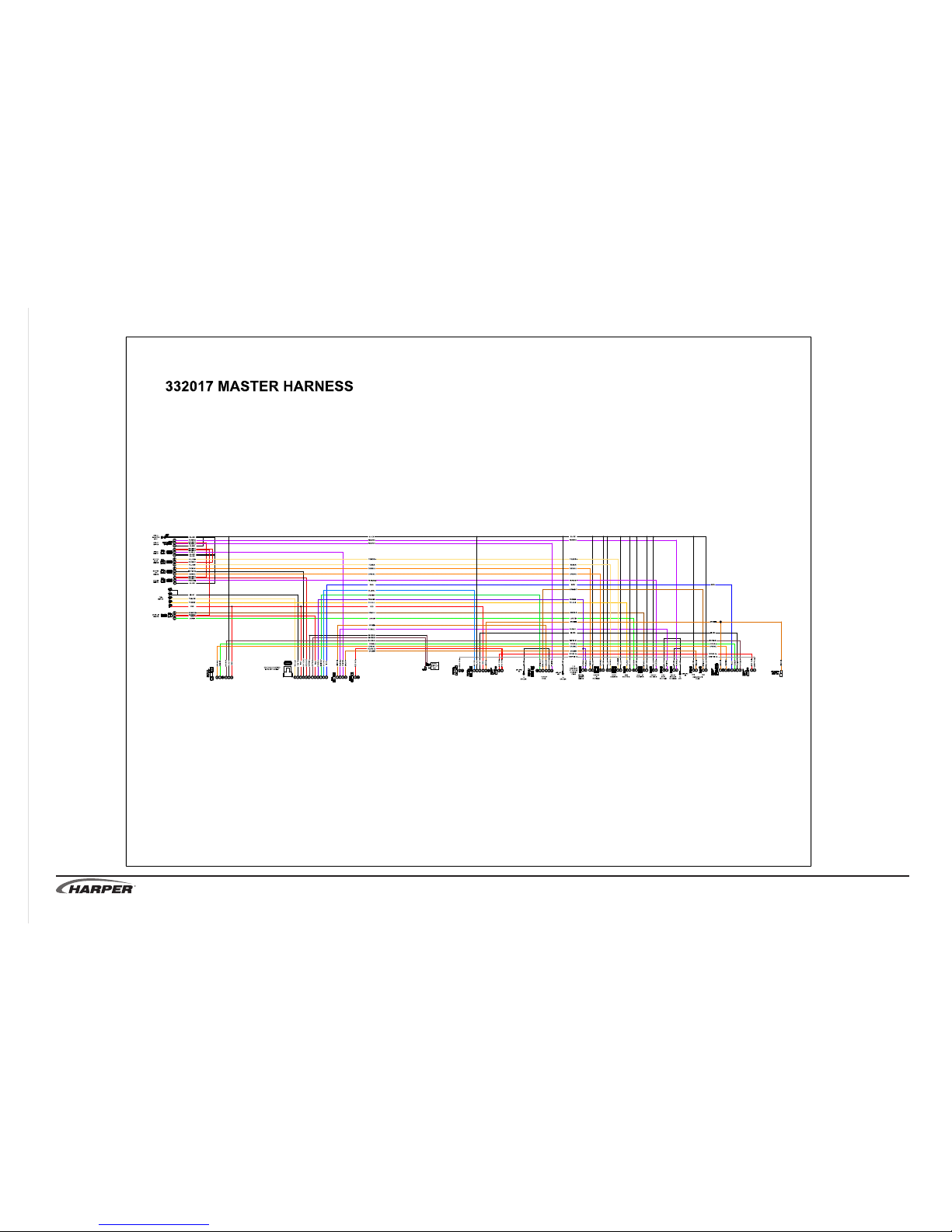
TV 30
R
3.2
Page 84
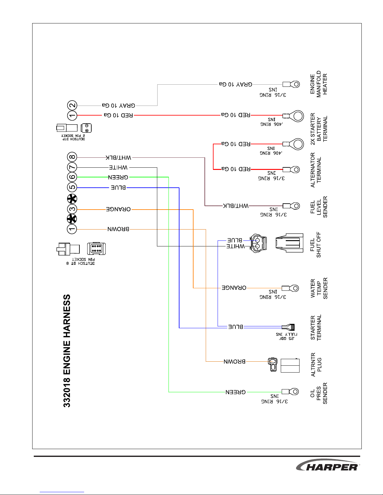
TV 30
R
3.3
Page 85
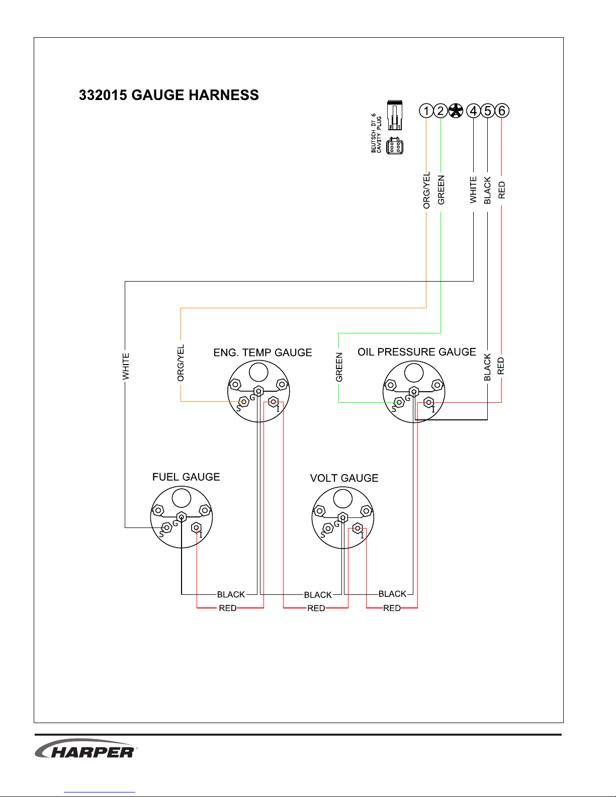
R
3.4 3.5
TV 30
Page 86
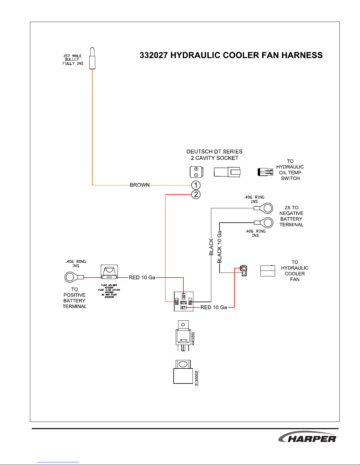
TV 30
R
3.5
Page 87
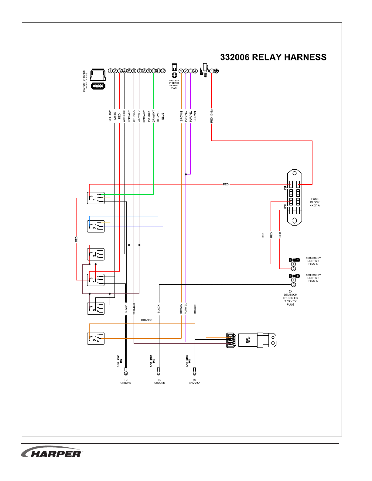
R
3.6
TV 30
Page 88
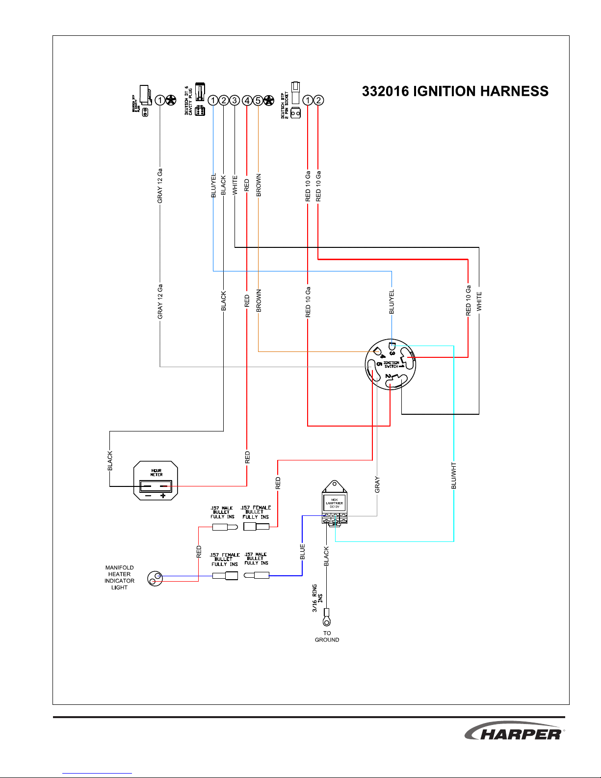
TV 30
R
3.7
Page 89
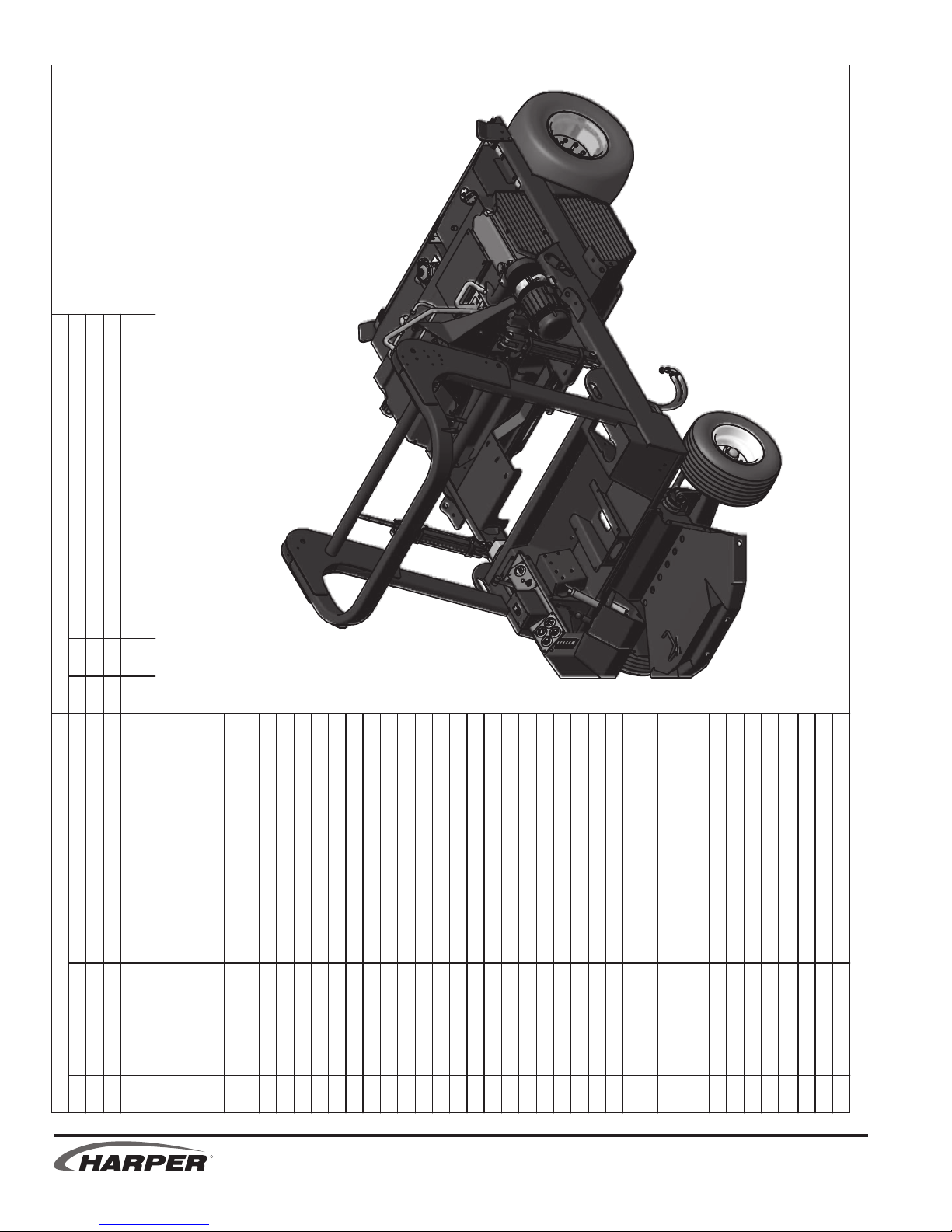
6/7/2011
SWITCH, SPDT, ON-ON
PARTS LIST
44 4 832008 SWITCH MOUNT, MIDDLE
45 1 832011 BATTERY
46 1 832018
ITEM QTY PART # DESCRIPTION
PARTS LIST
47 1 832024 MOUNT, SWITCH (VMS)
BOLT, 1/4-20 X .625 HEX GR 5
ELECTRICAL ASSEMBLIES
NUT, 1/4-20
NUT, 5/16-18 LOCK (NYLON)
BOLT, 10-24 X .375 STAINLESS, PHILLIPS
BOLT - TIE DOWN, BATTERY
CONTROLLER - FOOT PEDAL, OEM
PLATE - MOUNT, SWITCH AND HOUR MTR
OIL PRESSURE GAUGE
TEMPERATURE GAUGE
1 1 110020 Bolt, 5/16-18 X 0.75 in Carriage
2 4 110290 NUT, 1/4-20 WIZ FLANGE
3 4 110299
4 4 110441 BOLT, 5/16-18 X 4.0
5 2 110444 BOLT, 5/16-18 X 0.75, WIZ FLANGE
6 2 110459 BOLT, 5/16-18 X 1, WIZ FLANGE
7 4 110603
8 3 110606 NUT, 5/16-18 WIZ FLANGE
ITEM QTY PART # DESCRIPTION
49 2 110515 BOLT, 1/4-20 X .50
9 2 110609
10 6 110631 NUT, 10-24 LOCK NYLON INSERT
11 5 110665 WASHER, 5/16" FLAT STANDARD
12 1 110673 WASHER, 1/4" FLAT STANDARD
R
13 2 110709 SCREW, 10-24 X 0.75, RHMS
14 14 110788
15 1 110867 GROMMET - 2 ID X 1/8 X 2-5/8
16 2 110896 GROMMET - 1-1/2 ID X 1/4 X 2-1/8 OD
17 1 110922 PLUG - 7/8", LOCKING, NON-VENTED
18 1 311308 BRACKET - HOLD DOWN, BATTERY
19 1 311309
20 1 311395 PLATE - MOUNT, GAUGE
21 1 311396
22 1 311397 PAD - SWITCH
23 1 311454 COVER - RELAY, TV30
24 1 332005 GASKET
25 1 332005 SENDER - FUEL LEVEL, ELECTRIC
26 1 333002
27 4 510960 SCREW, 10-24 X 0.5, RHMS
28 1 530009 HOUR METER
29 1 530051 CABLE - BATTERY,
30 1 530052 CABLE - BATTERY,
31 1 530064
32 1 530065 GAUGE, FUEL
33 2 730006 INDICATOR LIGHT
34 1 800117 ENCLOSURE, MERCURY SWITCH
35 2 810375 MOUNTING BRACKET
36 1 810747 SWITCH SHIM
37 1 830002 VOLT METER
38 1 830008
39 1 830018 IGNITION SWITCH
40 1 832003 SWITCH, PADDLE, CARLING (280063)
41 3 832004 SWITCH, PADDLE, CARLING (29261)
42 2 832005 SWITCH, PADDLE, CARLING (29253)
43 2 832007 SWITCH MOUNT, END
TV 30
3.8 ii 3.8
Page 90

14
41
47
22
34
3
33
32
38
31
14
20
37
43
43
46
42
40
2
15
26
7
11
4
5
28
21
33
23
18
9
12
6
39
41
41
30
8
29
19
25
24
45
42
1
10
13
27
16
14
17
35
44
26
49
36
ELECTRICAL ASSEMBLIES
6/7/2011
TV 30
R
ii 3.8
Page 91

8
10
11
1
3
2
12
5
10
13
4
7/18/2011
9
OPTIONAL - LIGHT PACKAGE INSTALLATION
DESCRIPTION
SWITCH - TURN SIGNAL
CLAMP, ADEL AC4 .265 HOLE
2 4 110117
NUT, 5/16-18 WIZ FLANGE
110154 Bolt, 1/4-20 X 0.75 in Carriage
110630 NUT, 1/4-20 LOCK (NYLON INSERT)
4
3
4 8 110606
5 4
Bolt, 5/16-18 X 0.75 in Carriage
PARTS LIST
PART #
QTY
1 16 110020
ITEM
REFLECTOR - TAPE, RED
1 132073 SWITH - HAZARD
6 1 132072
7
8 2 302037
14
6
GUARD - LIGHT
LIGHT - WARNING, AMBER, LED
LIGHT - WORK LAMP, RECT, ASSEM
9 2 302038 REFLECTOR - TAPE, YELLOW
11 2 332009 LIGHT - STT/WARNING, RED/AMBER, LED
12 2 332010
10 4 311440
13 2 332011 LIGHT - WARNING, AMBER, RECT, LED
14 2 332012
R
3.9
TV 30
Page 92

NOTES
Harper Industries, Inc.
151 E. Highway 160
Harper, KS 67058
Website: www.harperindustries.com
TV 30
Telephone: 620-896-7381
Toll-Free: 800-835-1042
Fax: 620-896-7129
E-mail: info@harperindustries.com
R
Page 93

© 2011 Harper Industries, Inc.
All rights reserved. Printed in U.S.A.
R
TV 30
 Loading...