

Page 1
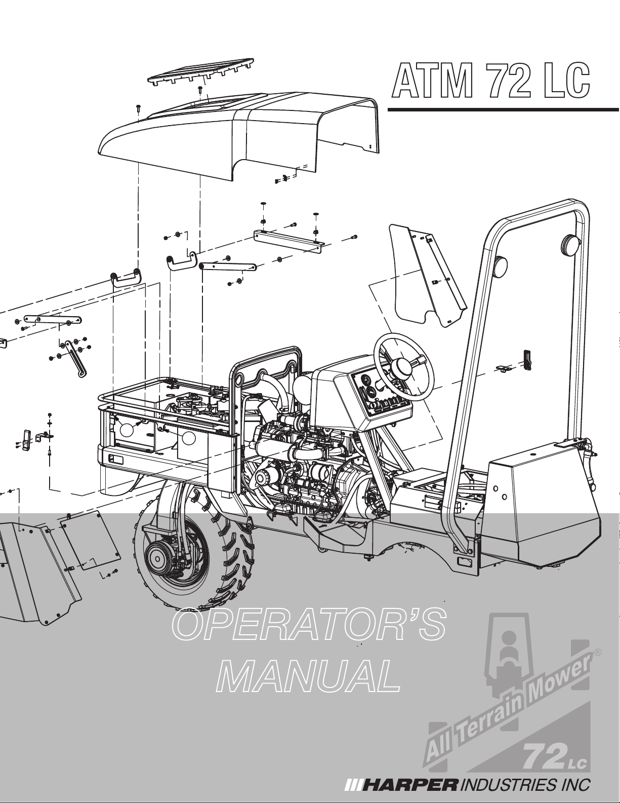
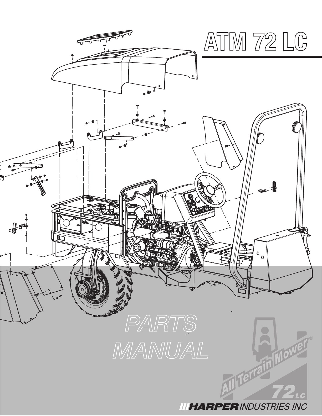
ATM 72 LC
R
6
5
OPERATOR’S
MANUAL
ATM 72 LC
3-2019
Page 2

ATM 72 LC
Page 3
Thank you for purchasing a Harper ATM 72.
TO THE OWNER OR OPERATOR:
Please take time to read this manual carefully before operating the ATM 72. Each operator should
be familiar with all safety precautions along with the operating and service procedures. Knowledge
and familiarity will make a difference in how the machine performs.
As with all Harper products, the ATM 72 was developed through tough design and testing procedures to produce a sturdy, dependable machine. This manual gives assembly and operating information. Read and understand all instructional materials included with the unit and its components
before operating or maintaining the equipment.
An All-Terrain Mower can present hazards to an operator who follows unsafe procedures in either
the operation or maintenance of the unit. Therefore, SAFETY WARNINGS are present at certain
locations in the text.
SYMBOL: SAFETY WARNING!
MEANING: Failure to understand and obey this warning may result in injury to you or others.
Whenever this symbol is used, please pay very close attention to the information presented, and
make sure you fully understand. If you do not, contact your dealer or Harper Industries for clarication.
SAFETY WARNING!
All shields and guards must be in place for proper and safe operation of this equipment.
Where they are shown removed in this manual, it is for purposes of illustration and instruction only. Do not operate this equipment unless all shields and guards are in place.
WARNING: Breathing diesel engine exhaust exposes you to chemicals known to
the State of California to cause cancer and birth defects or other reproductive harm.
• Always start and operate the engine in a well-ventilated area.
• If in an enclosed area, vent the exhaust to the outside.
• Do not modify or tamper with the exhaust system.
• Do not idle the engine except as necessary.
For more information go to www.P65warnings.ca.gov/diesel
© 2019 Harper Industries, Inc.
The Harper and DewEze names and the ATM logo are registered trademarks of Harper Industries, Inc. All other brand and product
names are trademarks or registered trademarks of their respective companies.
ATM 72 LC
1
Page 4

LIMITED WARRANTY
Harper Industries, Inc. (HII) warrants to each purchaser of a new Harper ATM from an
authorized dealer or representative, that such equipment is free of manufacturer’s defects
in workmanship and materials which appear while in normal service for a period of ONE
YEAR commencing with delivery to the original user.
The obligation of HII under this warranty is expressly limited, at our option, to replacement
or repair at a service facility designated by Harper Industries or at the manufacturing plant
in Harper, KS. A part will be replaced after inspection discloses it to have been defective.
This warranty does not apply to defects caused by damage or unreasonable use (including failure to provide reasonable and necessary maintenance, or by performing functions
without genuine Harper ATM accessories) while in the possession of the consumer.
Warranty is limited to parts, labor and ground freight delivery of replacement parts. HII
shall not be liable for the consequential damages of any kind, including but not limited to
consequential labor costs or transportation charges in connection with replacement or
repair of defective parts.
This warranty does not apply to parts subjected to misuse, abuse, alteration, improper or
inadequate maintenance, or normal wear (including blades, lters, and battery).
Engines are not covered under this warranty. Refer to manufacturer’s warranty for specic
warranty information. Harper Industries, its agents or representatives, make or imply no
other warranties.
Harper Industries makes no warranty with respect to trade accessories. They are subject
to the warranties of their respective manufacturers.
ANY IMPLIED OR STATUTORY WARRANTIES, INCLUDING ANY WARRANTY OR
MERCHANTABILITY OR FITNESS FOR A PARTICULAR PURPOSE, ARE EXPRESSLY
LIMITED TO THE DURATION OF THIS WRITTEN WARRANTY. HII makes no other express warranty, nor is anyone authorized to make any on behalf of HII.
For further information please contact your nearest Harper ATM dealer.
RECORDS
Date of Purchase ______ / ______ / ______
Dealer’s Name _________________________________
Dealer’s Phone _________________________________
Serial Number Machine __________________________
Serial Number Engine ___________________________
2
ATM 72 LC
Page 5

Table of Contents
Introduction
OPERATOR SECTION
To the Owner or Operator.................................................
Warranty Statement..........................................................
Table of Contents..............................................................
Introduction.......................................................................
Specications....................................................................
Control Identication.........................................................
Throttle...............................................................
Mower Switch.....................................................
Deck Lift.............................................................
Lights..................................................................
Ignition................................................................
Park Brake.........................................................
Manual Override.................................................
Deck Wing Raise/Lower.....................................
Manual Leveling.................................................
Inclinometer Switch............................................
Safety Guidelines
Equipment & Controls........................................
Safety Decals.....................................................
Diesel Fuel.........................................................
Guards & Shields...............................................
Battery................................................................
Hydraulics..........................................................
Safety Interlocks/Wiring Logic............................
Before Operation................................................
During Operation................................................
Maintenance
Hydraulic System...............................................
Grease Zerk Locations.......................................
Air Cleaner.........................................................
Cooling System..................................................
Engine Oil..........................................................
Fuel Filter...........................................................
Relay Panel........................................................
Deck Service Mode...........................................
10
10
11
11
12
12
12
1
2
3
4
5
6
6
6
6
6
6
6
6
6
6
6
The objective of Harper Industries in designing the ATM 72 LC was to create a mowing
machine that could function safely and comfortably on slopes and inclines. The result is
an All-Terrain Mower that will automatically
adjust itself to keep the operator in a vertical
position on all slopes up to 34 degrees.
Driving with an automatic leveling device will
be a new and different experience. After
several minutes of driving, the smooth control
and sturdy feel will become comfortable to
you. The security of always sitting upright and
the feel of powerful, positive traction will give
7
7
7
7
8
8
8
8
9
you condence and comfort in most mowing
situations.
However, we urge EXTREME CAUTION or
else your condence in these features get
you into trouble.
REMEMBER: The features of the ATM 72
9
cannot replace good common sense.
Tow Procedure/Transporting
Moving the machine w/o starting.......................
Park Brake Release...........................................
Opening the Bypass Valve.................................
Tie Down Locations............................................
Adjustments
Seat Adjustment.................................................
Deck Lift Adjustment..........................................
Cutting Height....................................................
Leveling..............................................................
Standard Torque Chart.....................................................
Service Parts....................................................................
Service Schedule..............................................................
Operating Guide...............................................................
ATM 72 LC
13
13
13
14
14
15
15
15
16
16
17
19
3
Page 6
Specications
Power Diesel - Kubota V1505-E4B 24.8 HP @ 2300 RPM
Main Frame Welded and formed steel frame
Decks • 2 - 36” decks (72” total cutting width)
• Independently free oating, with rear discharge
• Constructed of reinforced 10 gauge steel
Cutting Height 3 - 6” adjustable cutting height
Hydraulics
Speed
Options • Incline Meter Assembly - Part # 815052
Tires Drive Tire: 25” x 11-12 - 6 ply
Steering Power steering with automotive type steering wheel
Seat Adjustable ride suspension, arm rests, and retractable seat belt
Electrical 12 volt, 40 Amp Electrical System
Dimensions Length – 107 in., Height – 90 in., Width – 74.5 in.
Weight
Liquid Capacities Fuel – 10 Gallon; Hydraulic Fluid – 11.5 Gallon
Safety & Hydraulic
Oil
• Direct hydraulic blade drive (no belts or gear boxes)
• Poclain hydrostat - PM10 variable displacement axial piston pump
• Poclain high efciency axial piston wheel motors with integrated parking
brake.
• Hydraulic lter - 3 micron with indicator
• Hydraulic oil cooler
• 0-7 MPH ground speed
• Foot operated speed control - self-centering to neutral
• Factory Install Wheel Weight Kit - Part # 801005
• Customer Install Wheel Weight Kit - Part # 801004
• White Canopy - Part # 802039
• Red Canopy - Part # 802040
Stabilizer Tire: 16.5” x 6.5 x 8” foam lled
Deck Caster Tire: 11” x 4.00 x 5” foam lled
2480 lbs.
• Includes Certied ROPS with hazard lights (meets ANSI/OPEI B71.4 standards)
• Seat belt
• Crown AW46; ISO 46 Hydraulic Oil
NOTE: Following publication of this manual, certain changes in standard equipment and/or options
may have occurred which would not be included in these pages. Your Harper dealer is the
best source for up-to-date information.
ATM 72 LC
4
Page 7

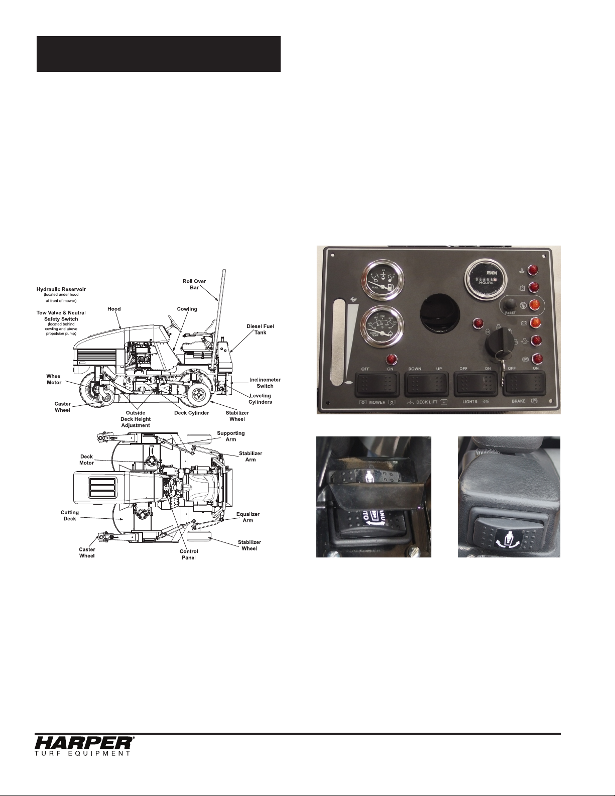
Control Identication
Diesel Fuel Tank
(located under hood
at front of mower)
Roll Over
Bar
Tow Valve & Neutral
Safety Switch
(located behind
cowling and above
propulsion pump)
Wheel
Motor
Caster
Wheel
Outside
Deck Height
Adjustment
CowlingHood
Deck Lift
Cylinder
Hydraulic
Reservoir
Inclinometer
Module
Leveling
Cylinders
Stabilizer
Wheel
Supporting
Arm
Deck
Motor
Cutting
Deck
Caster
Wheel
ATM 72 LC
Stabilizer
Arm
Equalizer
Arm
Stabilizer
Control
Wheel
Panel
5
Page 8
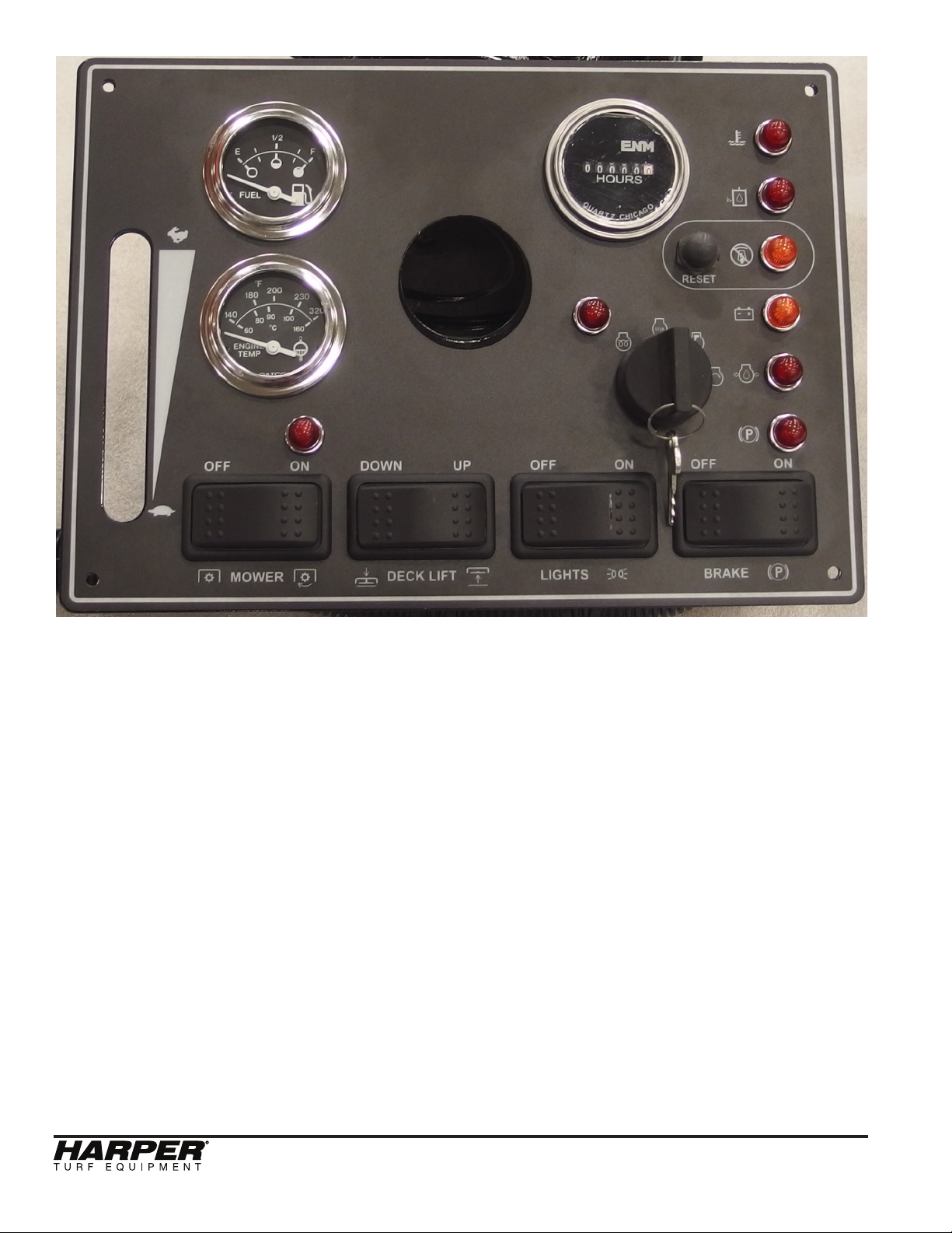
Engine Temp
Hydr. Level
Throttle
Mower Deck
Deck Lift Lights BrakeMower
Throttle – adjust engine speed with throttle.
Start at low throttle, allow engine to warm up,
then operate unit at full throttle.
Mower Switch – turns the deck blades on
and off allowing user to cut the grass.
Deck Lift Switch – raises and lowers the
mower deck.
Lights Switch – turns on headlights.
Leveling
Momentary
Lockout
Reset
Engine
Battery
Pre-Heat
Engine Oil
Ignition
Parking Brake
Momentary Reset Switch– resets the auto
level function after the machine has been
locked out. Once the machine is level, the
reset button can be pushed to turn on the
auto level function.
Mower Deck Light – is on when the mower
blades are engaged.
Engine Pre-Heat Light – turns on when the
key is in the pre-heat position.
Ignition – turn the key to the left until the
pre-heat light turns off. Then, turn key to right
to start unit. Remove key when unit is not in
use. Never leave unit unattended with key in
ignition.
Park Brake – set park brake when unit is not
in use or is parked on an incline. Make sure
park brake is disengaged before operation.
Engine Temp Light – turns on when the engine temp exceeds 215° F.
Hydraulic Level Light – turns on when the
hydraulic oil is low.
Leveling Lockout Light – turns on when the
auto level funtion has been locked out.
ATM 72 LC
6
Page 9

Battery Light – is on when the charging system voltage is low.
Engine Oil Light – turns on when the oil
pressure drops below 7 psi.
Parking Brake Light – is on when the park
brake is applied
Manual
Leveling
Manual
Auto/Manual
Leveling
Leveling
.
Manual Leveling Switch – one is located
on the arm rest and the other on the ROPS.
Both of these switches perform the same
function. One is intended to be used while
in the operator’s seat and the other for when
standing behind the machine. They are used
to manually tilt the machine left or right.
Auto/Manual Leveling Switch – determines
if the machine is leveled automatically using
the signal from the inclinometer module or
leveled only using the manual leveling switch.
Inclinometer Module – senses if the machine is off center/vertical. The machine can
lean to either side up to 34° before reaching
its limit.
• The inclinometer module includes a
dual axis (XY) accelerometer. It
measures the force caused by
movement of the sensor (accelera tion). Gravity puts a force on the
sensing elements that can be mea sured. The sensor is an analog device
with a voltage for X and a voltage for
Y. The module uses the voltage
outputs from the sensor to determine
the angle of the machine.
• When the inclinometer module mea sures an angle 4 degrees or greater
from center, it sends a +12 V signal to
the hydraulic valve to operate the
appropriate leveling cylinder to return
the machine to an upright position.
SAFETY WARNING!
Do not leave ATM 72LC unattended, or
attempt any service or inspection unless
the machine has come to a complete stop
and the engine has been shut off.
ATM 72 LC
7
Page 10

Safety Guidelines
Equipment & Controls
• Read and understand this manual.
• Altering this equipment in any manner
which adversely affects its operation,
performance, durability, or use will void
the warranty and may cause hazard ous conditions.
• Know the location and function of all
controls and how to stop this equip ment quickly in an emergency before
you operate the equipment.
• Keep all nuts, bolts and screws tight to
help ensure safe operation of this
equipment.
• Use genuine factory parts or parts with
equivalent characteristics, including
type, strength and material. Failure to
do so may result in product malfunc tion and possible injury to the operator
and/or others.
• If hardware is not secure, or if some of
the hardware is over-tightened, equi pment failure may result, posing pos sible safety hazards.
• To prevent possible eye injury, always
wear SAFETY GLASSES while oper ating equipment.
• Always wear a respirator when work ing in dry/dusty conditions.
Diesel Fuel
• Always use an approved container for
transporting diesel fuel.
• Do not allow open ames or sparks
while performing maintenance or refu eling.
• Never remove fuel tank cap or add
fuel when engine is running or while it
is hot.
• Only use ultra low sulfur diesel.
• Never ll fuel tank indoors. Fumes are
heavy and will sink to the lowest point,
collect and become hazardous.
• Wipe up spilled fuel immediately.
• Do not store fuel in a room with an ap pliance that has a gas pilot or electri cal switch that may cause sparks.
• Always store diesel outside in a safe-
ty can (a can with ame arrestor and
pressure relief valve in pour spout).
• Never store the equipment with fuel in
the tank inside a building where fumes
may reach an open ame or spark.
• Allow the engine to cool before storing
in any enclosure.
• Be certain to provide adequate ventila tion if an engine must be run indoors -
exhaust fumes are dangerous.
SAFETY WARNING!
Diesel fuel is extremely ammable and can
be highly explosive.
Safety Decals
• If safety related or instructional decals
become illegible or are removed, re place them immediately. New decals
may be obtained from your local Harp er Dealer.
• If you replace parts that have such
decals attached to them, make sure
the decals are replaced with current
versions, and are on the replacement
parts before the machine is operated
again.
Guards & Shields
• Keep all safety devices in place.
• Replace all worn, damaged, unusable,
missing or lost safety shields and
guards before operating the equip ment.
• Keep the equipment in good operating
condition.
ATM 72 LC
8
Page 11

Battery
SAFETY WARNING!
Batteries can produce explosive gas.
Use extreme caution when working on
the battery.
• Ventilate when charging battery or us ing in an enclosed space.
• DO NOT produce sparks from cable
clamps, tools, or other sources; and
DO NOT allow ames or smoking in
the vicinity of the battery.
• Shield eyes when working near bat tery.
Hydraulics
SAFETY WARNING!
Escaping uid under pressure can
penetrate skin causing serious injury.
To prevent serious injury or death:
• Relieve pressure on system before
repairing, adjusting or disconnecting.
• Wear proper hand and eye protection
when searching for leaks.
• Use wood or cardboard instead of
hands when looking for leaks.
• Keep all components in good repair.
• Do not use any type of heat (welding,
soldering, cutting torch, etc) near
pressurized lines.
Safety Interlocks/Wiring Logic
• To start the machine, it must be in
neutral and the blades must be off.
• To turn the mower blades on, the
operator must be in the seat, and the
hydraulic oil temperature must be
below 190° F.
• There is a 2 second time delay added
to the seat switch to account for
bounce.
• The park break is applied when the
operator is out of the seat.
• Leveling
1. Valves on the cylinders are open
when in auto mode or when the
manual switch is activated to level the
machine.
2. If the inclinometer senses that the
machine is not stable or that the
machine has changed angle at a quick
rate, the valves on the leveling
cylinders are closed to lock the
machine in its current position. When
this happens, the leveling lockout indi cator light on the dash will be illumi nated. To reset the auto level
function, press the momentary reset
switch on the dash.
Before Operation
• Before operating this equipment, read
and understand the Owner’s Manual.
• Do not allow children to operate this
machine.
• Wear approved eye and ear protection
and other appropriate safety equip ment while operating the machine.
• Check tire pressure and ll to
specications.
• Engine settings are preset and should
not be changed; any change can dam age moving parts and void the war ranty.
• Before starting the machine, visually
inspect all nuts, bolts and other fasten ers to see that they are properly se cured. Nuts, bolts and other fasteners
should be checked every 8 to 10 hours
of operation for proper alignment and
tightness.
• Replace damaged or missing safety
decals.
• Use factory authorized parts or their
equivalent.
• Make sure that all bearings or hinging
parts are greased and or oiled prop erly.
ATM 72 LC
9
Page 12
During Operation
• Always keep a re extinguisher near
the mower during operation.
• Keep clothing and all body parts away
from rotating parts.
• Keep the engine area clean from de bris and other accumulations to lessen
the possibility of re.
Maintenance
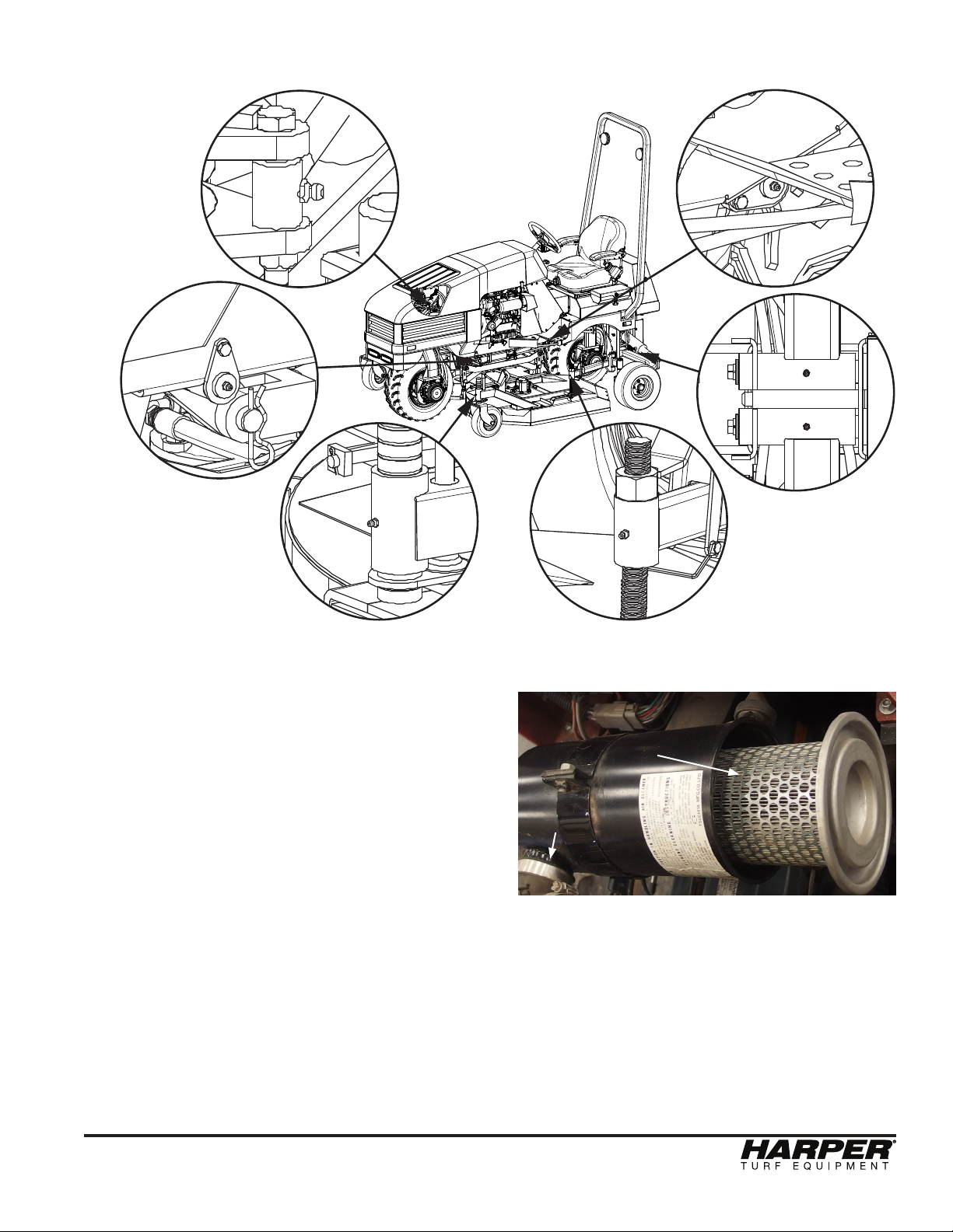
Hydraulic System
• The hydraulic system of the ATM72LC
is lled at the factory with Crown AW
46 hydraulic oil that has an ISO of 46.
• The ATM72LC has a 3 micron, beta
rated hydraulic oil filter designed for
long life.
Oil Fill
Sight
Glasses
(left hand side)
Hydraulic
Reservoir
Oil Filter
• On a daily basis, monitor the needle in
the filter indicator when the oil is at
normal operating temperature.
Yellow
Red
Green
The following list of hydraulic fluids are compatible and can be mixed with Crown hydraulic fluid. MIXING OTHER OILS THAT ARE
NOT INCLUDED ON THIS LIST COULD
CAUSE GELLING AND DAMAGE TO THE
HYDRAULIC COMPONENTS. If another
type of oil is desired, then the system must
be completely drained and flushed first.
Appropriate replacements:
ISO 46: Recommend for running in ambient
air temperatures of 32°F-110°F, and it contains a kinematic viscosity rating around 46
cSt at 40°C. (1cSt = 1mm²/s)
• Mobil DTE 25
• Mobil DTE 15M
• Amoco Rykon Premium Oil ISO 46
• Chevron Rykon Premium Oil ISO 46
• Conoco Hydroclear AW MV 46
• Exxon Univis N 46
• Pennzoil AWX MV 46
• Shell Tellus T 46
• Texaco Rando HDZ 46
Filter Indicator
Hydraulic
Filter
• The filter (part no. 822044) does
not need replaced until the needle is in
the red portion of the gauge.
• To replace filter , twist the filter
counter-clockwise. Replace with new
filter by turning it clockwise until tight.
• The hydraulic oil level should be moni tored daily with the hydraulic tank’s
sight glasses on the left hand side of
the hydraulic tank.
• Keep the hydraulic oil just above the
lower sight glass at all times.
• Fill reservoir through the fill location on
top of the reservoir.
10
ATM 72 LC
Page 13
Grease Zerk Locations
*
*
*
* Denotes a second grease zerk identical to this one on the other side.
PROCEDURE
1) Park on level ground and set park
brake.
2) Turn off ATM.
3) Give 2 to 3 shots of grease after every
10 hours of use.
*
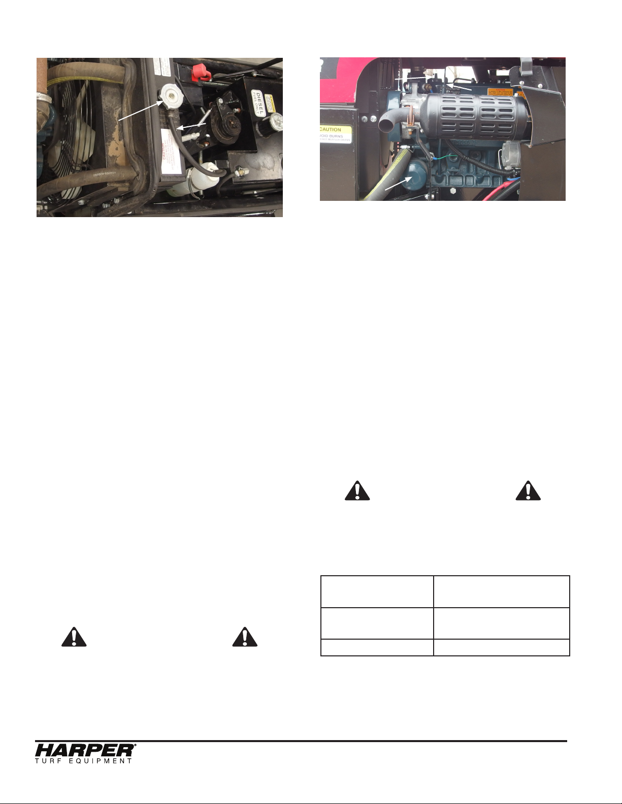
Air Cleaner
Air Filter
Air Intake
• Make sure intake is always free of
debris.
• When engine is turned off, remove the
wing bolt.
• Replace the air filter according to the
Maintenance Schedule.
(view from the bottom)
ATM 72 LC
11
Page 14
Cooling System
Engine Oil
Hydraulic
Oil Cooler
Radiator Fill
Radiator
Coolant Recovery
Bottle
• The radiator and hydraulic oil cooler
are located side by side in the same
aluminum heat exchanger.
• Clear hydraulic oil cooler and radiator
of debris with pressurized air daily or
as needed.
• Check radiator level daily and only
when engine is cool and not running.
• Remove cap (radiator fill) slowly to
relieve any pressure that may be built
up.
• Fill up radiator with coolant (50% wa ter/ 50% antifreeze) until coolant is vis ible in neck of radiator.
• Make sure that the coolant recovery
bottle has at least 1” of coolant in bot tom. The presence of coolant in the
recovery bottle does not mean radiator
is full.
• Do NOT operate the machine if the
engine temperature exceeds 220°F.
Severe engine damage may occur if
the machine is continuously operated
above 215°F. If overheating does
occur, diagnose the cooling system
and ensuring proper coolant levels and
proper air flow across the radiator.
SAFETY WARNING
Hot Coolant and steam from the radiator
can cause severe burns. Never open the
radiator cap of a hot engine.
Engine Oil Fill
Dipstick
Engine Oil Filter
• The dipstick and engine oil fill are lo cated on top of the engine.
• The engine oil filter is located on the
left side of the engine as viewed from
the operator’s seat.
• To get to the engine oil fill or dipstick,
the hood should be raised.
PROCEDURE
• Check engine oil level only when en gine is turned off.
• Keep engine oil level between the
FULL and ADD marks on dipstick at all
times. DO NOT OVER-FILL.
• Add engine oil (S.A.E. 10W30) through
the engine oil fill location.
• Replace the engine oil/filter according
to the Maintenance Schedule.
SAFETY WARNING
Keep dipstick and oil fill cap secured
tightly. Engine oil may escape through
these orifices when engine is running
causing severe burns.
above 25°C (77°F) SAE30 or SAE10W-30
SAE15W-40
-10°C - 25°C
(14°F - 77°F)
SAE10W-30
SAE15W-40
below -10°C (14°F) SAE10W-30
• Filled with SAE10W-30 from the
factory, 6.0 L capacity, and change
after the first 50 hours.
12
ATM 72 LC
Page 15
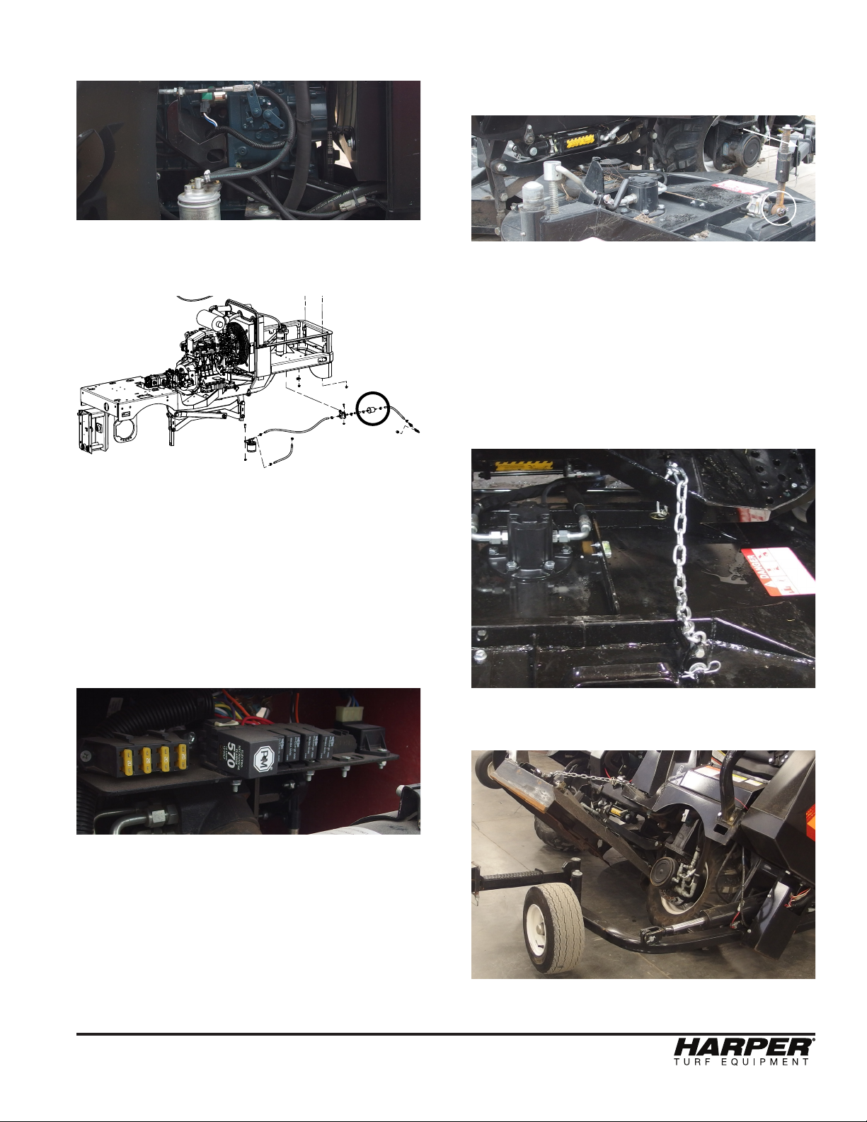
Fuel Filter
Fuel Filter
Deck Service Mode
• Remove hairpin cotter and at-washer
and swing out support arm.
Support Arm
• Fuel filter is located on the right side
of the machine when viewed from the
operator’s seat.
Smaller
Fuel Filter
• There is also a smaller in line fuel filter
on the bottom of the front right corner
of the machine leading from the fuel
tank to the main fuel filter.
• The Fuel Shut-off valve is located
on the lower right side of the fuel tank.
It can be accessed from below the
machine.
Pin
• Connect chain to deck and replace
pin
• With Manual Override switch, lean
mower all the way left or right. Then
insert chain into chain cutout located
on the step. Install the lynch pin in
the bottom side of the step for added
safety. After that lean the mower to
the opposite side.
Relay Panel
• Located under the hood behind the
dash of the mower.
ATM 72 LC
• Block deck up before working under
the deck.
13
Page 16
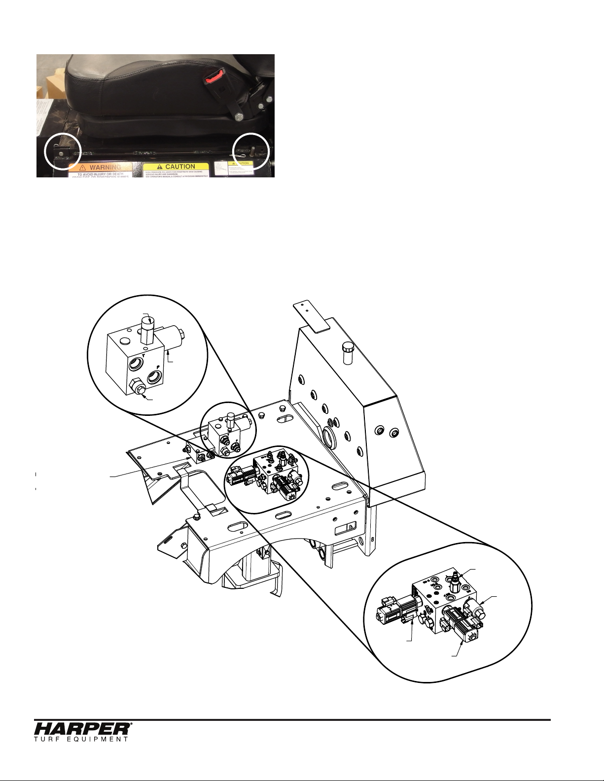
Hydraulic Valves
• To get to the hydraulic valves, either
remove the two rear pins holding the
seat down and rotate the seat forward
or remove all (4) pins holding the seat
down and remove the seat all together.
DECK
VALVE
LOOP
FLUSH
VALVE
PRESSURE
RELIEF
COUNTER
BALANCE
VALVE
MOWER
BLADE
COIL &
SOLENOID
AUXIALLARY
VALVE
PRESSURE
RELIEF
BRAKE
RELEASE
COIL &
SOLENOID
14
DECK LIFT
COILS &
SOLENOID
LEVELING
COILS &
SOLENOID
ATM 72 LC
Page 17
Tow Procedure
Moving the machine without starting the
engine
• In order to move the machine without
the engine running, the park brakes
must be released and the bypass
valve must be opened on the propul sion pump.
• After towing the unit, follow procedure
in opposite order to remove brake
release tool and install new plastic
plug.
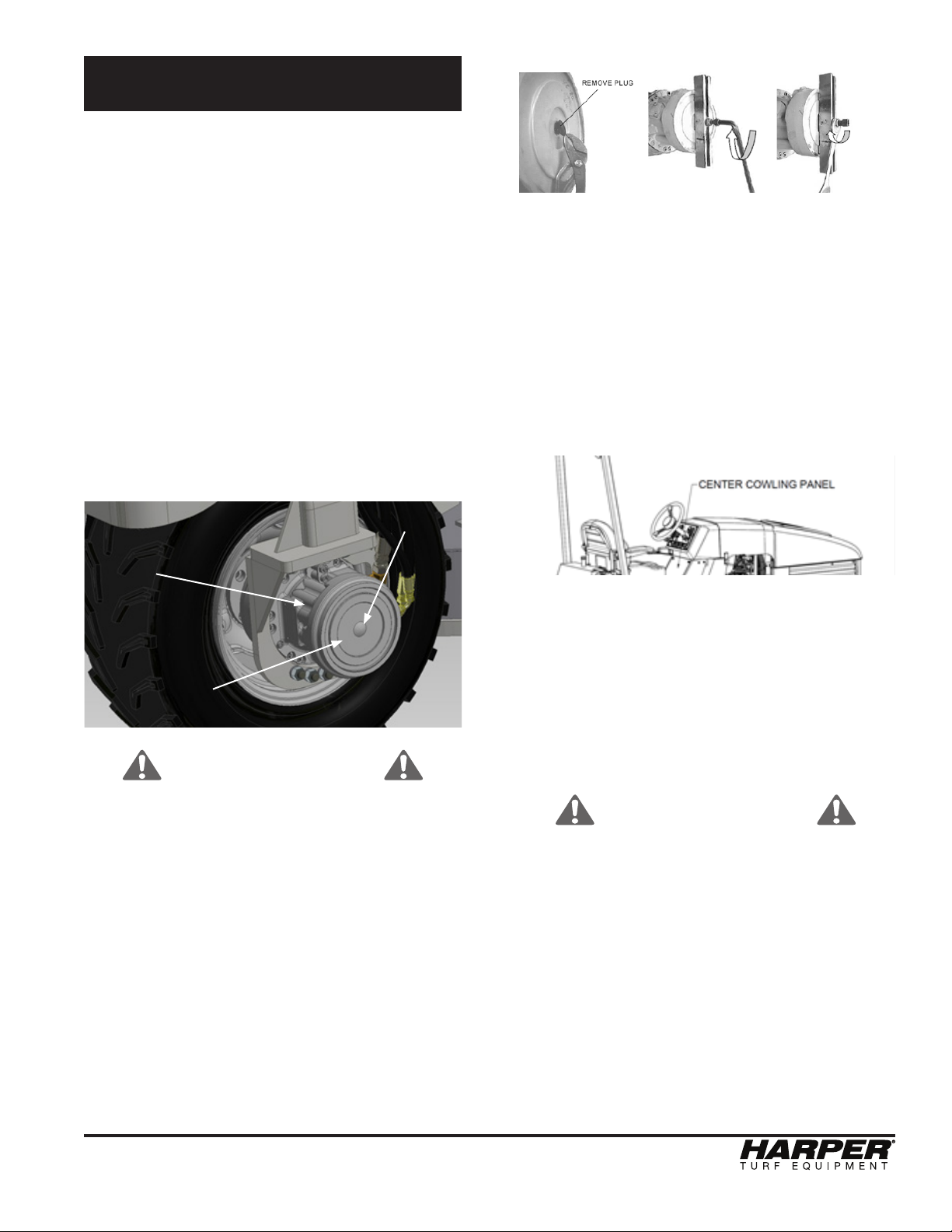
Park Brake Release
• Both of the wheel motors contain a
park brake that is mechanically applied
and hydraulically released. Whenever
the engine is off (zero system pres sure), the brakes are applied.
• Always release the park brakes when
towing or pushing the unit.
Plastic Plug
Wheel Motor
Park Brake
Release
(behind cover)
PRECAUTION
• Towing or pushing the unit with the
park brakes applied may cause seri ous damage to internal brake parts.
PROCEDURE
1. Remove plastic plug from the center of the
park brake housing.
2. Install brake release tool (P/N 575064)
by placing on brake housing and tighten ing the screw into the piston. These tools
can be found inside the toolbox.
3. Tighten the nut until the motor shaft turns
freely.
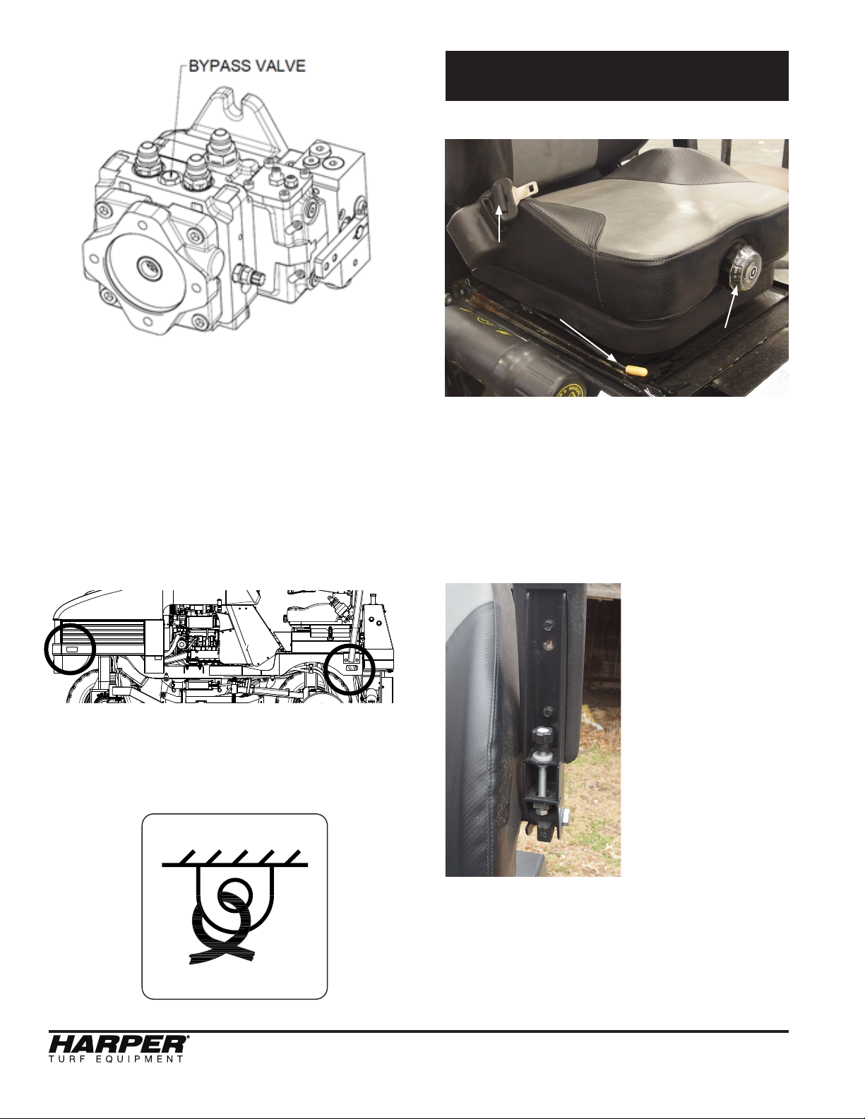
Opening the Bypass Valve
• The bypass valve is located on the
top side of the propulsion pump be tween the high-pressure ports. The
valve can be accessed by removing
the center cowling panel.
• Open the bypass valve when moving
the machine for short distances. The
bypass valve connects the high-pres sure ports A & B. Only use this valve in
an emergency case and for a short
distance.
• The bypass valve is not a tow valve and
can not be used to pull the machine for
a long distance.
PRECAUTIONS
• The bypass valve is intended only for
moving a vehicle a very short distance
and is not intended for towing a vehicle
behind a truck or tractor. Note: Serious
damage to the hydrostatic drive will
result if the vehicle is towed.
• Close the bypass valve tightly when
nished moving unit. Failure to close
valve tightly will result in full or partial
loss of power.
ATM 72 LC
15
Page 18
PROCEDURE
• To open the bypass valve, turn it coun ter-clockwise. It can be completely re
moved from the pump housing.
However, to avoid oil leakage, only turn
the valve 2 turns.
• After the machine has been moved,
reinstall the bypass valve and reinstall
the center cowling panel.
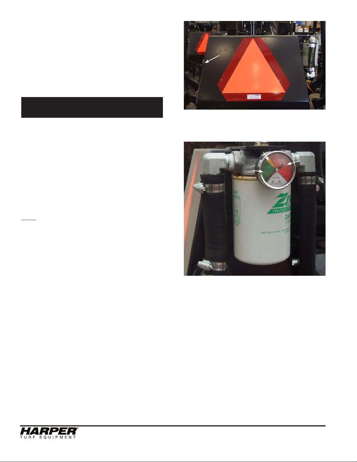
Tie Down Locations
Adjustments
Seat Adjustment
Seat Belt
Seat Front to
Back Lever
Seat Firmness
Knob
• The lever with the yellow handle
controls the chair’s forward and back
movement to allow for either more or
less leg room.
• The round knob adjusts the ride quality.
Turn the knob clock-wise for a rmer
ride, and counter-clockwise for a softer
ride.
There are (4) tie down locations designated on
the machine that are located at the front and
rear of each side of the machine, and they are
accompanied by the following decal:
• Adjust the
screw to change
the angle of the
arm rests.
Arm Rest
Angle Screw
• The seat
belt is retractable
and will lock up
on impact or
accident.
16
ATM 72 LC
Page 19
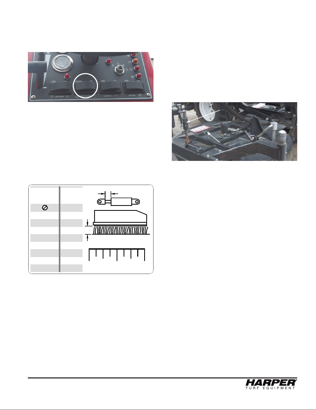
Cutting Height
X
Y
802068
1 2
0.25"
0.50"
0.75"
1.00"
1.25"
1.50"
1.75"
X
CYLINDER
SPACER
Y
CUT
HEIGHT
2.00"
3.00"
3.25"
3.50"
4.00"
4.50"
4.75"
5.00"
5.50"
6.00"
• Park the machine on level ground.
• Start the machine and raise the deck
using the switch on the dash.
• Using the crank located on the caster
wheels, raise the caster wheels so that
the deck is not supported by the caster
wheel. Turn CCW until the wheel is not
touching the ground. Repeat this step
for both sides.
• Using the outer deck screw adjustment,
adjust the deck so that it is level with
the center of the deck. A bubble level
is mounted on the deck for ease of
adjustment. Repeat for both sides.
• Using the decal on the side of the frame
or the picture below, identify the
cylinder spacer(s) needed to achieve
the desired cut height. The cylinder
spacers are located in the tool box on
the LH side of the seat frame. The
spacers provided include:
2 - 0.25”
1 - 0.50”
1 - 1.00”
Outer Deck
Adjustment
Hand Crank
Level
• Lastly, adjust both caster wheels down
until they touch the ground.
• Install the cylinder spacer(s) onto the
deck lift cylinder (see pg. 5 for
location).
• Lower the deck all the way down using
the switch on the dash.
• The outer deck height is controlled by
the arm linkage attached to the
stabilizer arm.
ATM 72 LC
17
Page 20

Standard Torque Chart Service Parts
SAFETY WARNING!
Refer to the Standard Torque Chart whenever bolts, nuts or screws are tightened.
PRECAUTIONS
• When tightening two or more fasteners
on the same part, DO NOT tighten
the fasteners completely one at a
time. To avoid distortion, first tighten
all fasteners in sequence to one-third
of torque value, then tighten to
two-thirds of torque value, then tighten
to full value.
• All lug nuts should be torqued to
140 ft-lbs (190 N-m).
Filters
Engine Air Filter.......................
Engine Oil Filter.......................
Fuel Filter (Cannister)..............
Fuel Filter (Inline)....................
Hydraulic Oil Filter...................
Belts
Engine Fan Belt.......................
Blades
RH Swinging Blade Set...........
LH Swinging Blade Set............
Swinging Blades Bolt Kit
(1 Deck Only) ...............
RH Fixed Blade Set.................
LH Fixed Blade Set..................
Fixed Blades Bolt Kit
(1 Deck Only)................
802064
302058
302057
302103
822044
802063
500269
500268
500319
500271
500270
500320
Wheels and Tires
Stabilizer Wheel Assembly......
Caster Wheel Assembly...........
Drive Wheel.............................
Drive Tire.................................
Drive Wheel and Tire Assy.......
800057
800093
842019
842020
843007
18
ATM 72 LC
Page 21

ATM 72 LC
19
Page 22

Service Schedule
Daily or Before Starting the Engine
□ Check Engine Oil Level...................................... SAE 10W30
• (See Maintenance section for details)
□ Check Hydraulic Oil Level.................................. Crown AW46
• (See Maintenance section for details)
□ Check Fuel Level............................................... Clean #2 Diesel Fuel
□ Visually Inspect.................................................. Fan belt, bolts, fittings, hoses, or any
damaged parts
□ Check Radiator & Oil Cooler.............................. Clean off debris as needed
□ Check Engine Screens………...…..................... Clear debris as needed to ensure proper
air flow
□ Check Air Cleaner Intake................................... Clear debris as needed
□ Check Engine Coolant Level.............................. 50% anti-freeze, 50% water
□ Grease............................................................... Refer to page 10
□ Check Drive Tires............................................... Visually inspect tires to ensure proper
inflation & no damage
Every 50 Hours
□ Change Engine Oil & Filter................................. After initial 50 hours, change engine oil
• (every 200, thereafter)
□ Change Inline Fuel Filter.................................... After initial 50 hours, change filter
• (P/N: 302103, every 200 thereafter)
□ Check Tire Pressure........................................... Inflate drive tires to 15 psi
□ Check of Fuel Pipes & Clamps........................... See Kubota Manual for details
□ Check Lug nuts................................................... Torque to 140 ft-lbs
Every 100 Hours
□ Check Engine Air Filter....................................... Clean or replace as needed (P/N: 802064)
□ Check Fan Belt Tightness.................................. Tighten as needed
□ Check Hydraulic Oil Filter................................... Replace when needed (P/N: 822044)
Every 200 Hours
□ Change Engine Oil............................................. SAE 10W30 or other approved oil
• (See engine manual)
□ Change Engine Oil Filter..................................... P/N: 302058
□ Check Intake Air Lines........................................ Clear debris as needed
□ Replace In-line Fuel Filter…………...................... P/N: 302103
□ Check Radiator Hoses & Clamps....................... Repair or replace as necessary
Every Year
□ Replace Engine Air Filter.................................... P/N: 802064
□ Check Hydraulic Oil Condition............................ Crown AW46
• (See Maintenance section for details)
□ Check Battery..................................................... Clean terminals if necessary
20
ATM 72 LC
Page 23

Every 500 Hours
□ Replace Engine Fan Belt.................................... P/N: 802063
□ Replace Cannister Fuel Filter............................. P/N: 302057
Every 1500 Hours
□ Check fuel injection nozzle injection pressure ...See Kubota Manual
□ Change Hydraulic Oil......................................... Crown AW46
• (See Maintenance section for details)
Every 3000 Hours
□ Check Fuel Injection Pump
Every Two Years
□ Change Engine Coolant..................................... 50% anti-freeze, 50% water
□ Replace Battery.................................................. P/N: 832011
□ Replace radiator hoses and clamp bands.......... See parts manual
□ Replace fuel hoses and clamp bands................ See parts manual
□ Replace air intake hose...................................... See parts manual
ATM 72 LC
21
Page 24
ATM72 LC Operating Guide
BEFORE OPERATION
• Safety Checklist
o Read and understand the Operator’s Manual (located in the manual holder to the left of
the seat).
o Clear all foreign objects such as rocks, bottles or other hard materials that lay in the area
to be mowed.
o Follow all procedures described in the Maintenance section.
o Fill with #2 diesel fuel, if needed, while engine is cool.
o Visually check tires.
o Visually inspect machine for loose ttings, fasteners, hoses, etc.
o Know the location and function of all controls and how to stop quickly in an emergency.
o Adjust seat to a comfortable position.
o Fasten safety belts.
Throttle
Mower Deck
Engine
Pre-Heat
Ignition
Momentary
Reset
Engine Temp
Hydr. Level
Leveling
Lockout
Battery
Engine Oil
Parking Brake
Deck Lift Lights BrakeMower
Manual
Leveling
Manual
Auto/Manual
Leveling
Leveling
• Perform the daily maintenance checklist (For details, see the maintenance section of the Opera tor’s Manual).
o Check engine oil level o Grease all zerks (see page 10)
o Check hydraulic oil level o Check drive tires
o Check fuel level
o Visually inspect the fan belt, bolts, fittings, hoses, or any damaged parts
o Check radiator and oil cooler
o Check engine screens
o Check Air cleaner intake
o Check engine coolant level
22
ATM 72 LC
Page 25

STARTING
• To start the machine, it must be in neutral and the mower blades must be turned off.
• Turn the key over until the mower starts, and release the key.
• Set the cutting height following the direction laid out on page 15.
DURING OPERATION
• FASTEN SEAT BELT
• To prevent possible eye injury, always wear SAFETY GLASSES while operating machine.
• Park Brake – Make sure the park brake is disengaged before operation. Set the park brake
when unit is not in use or is parked on an incline. The indicator light illuminates when the park
brake is set.
• The park break is applied when the operator is out of the seat.
• Throttle – Start at low throttle. After allowing engine to warm up, operate machine at full throttle.
• To turn the mower blades on, the operator must be in the seat, and the hydraulic oil temp
must be below 190° F.
• Mower Switch - Used to engage the mower blades.
• Manual Override Switch - It is used when the operator would like to lean the mower either way
on their own using the Manual Leveling Switch on the right arm rest, otherwise it should be left
alone to allow the machine to auto-level itself up to 34° either way.
• Deck Wing Raise/Lower - This switch can raise and lower he deck wings in order to avoid
obstacles that may be in the machines path. Be sure to disengage the Mower Switch before
raising deck wings.
• Lights Switch - Use the lights as needed to avoid obstacles that could damage the machine or
harm the operator in any way.
ATM 72 LC
23
Page 26

NOTES
Harper Industries, Inc.
151 E. Highway 160
Harper, KS 67058
Website: www.harperindustries.com
Telephone: 620-896-7381
Toll-Free: 800-835-1042
Fax: 620-896-7129
E-mail: info@harperindustries.com
ATM 72 LC
Page 27
ATM 72 LC
R
6
5
PARTS
MANUAL
ATM 72LC
7-2019
Page 28

ATM 72LC
Page 29

Table of Contents
Parts Section
Frame & Assemblies
Front Steering Assembly...................................
Rear Stabilizer Arm Assembly...........................
Deck Linkage Installation..................................
Engine Assembly..............................................
Engine Installation............................................
Fuel Tank Installation........................................
Steering Tower and Foot Pedal Installation......
Console Assembly............................................
ROPs and Steering Wheel Installation.............
Electrical Assembly...........................................
Hood and Cowling Installation..........................
Toolbox and Deck Lift Assembly.......................
Seat and Screens Assembly.............................
Wheel and Tire Installation...............................
Deck Assembly.................................................
Deck Installation...............................................
Decal Layout.....................................................
Hydraulic Systems
Hydraulic Schematic.........................................
Hydraulic Tank Assembly..................................
Propulsion Pump and Wheel Motor Assy..........
Valve Assemblies..............................................
Valve and Tank Installation...............................
Propulsion System............................................
Propulsion Circuit ..............................................
Propulsion Plumbing - Pump and Valves..........
Propulsion Plumbing - Wheel Motors...............
Machine Hydraulic System...............................
Gear Pump Assembly and Plumbing................
Steering Circuit.................................................
Steering Plumbing............................................
Auxilary Circuit..................................................
Deck Lift Plumbing............................................
Leveling Plumbing............................................
Deck Circuit......................................................
Deck Plumbing..................................................
Oil Cooler Plumbing..........................................
1.1
1.2
1.3
1.4
1.5
1.6
1.7
1.8
1.9
1.10
1.11
1.12
1.13
1.14
1.15
1.16
1.17
2.1
2.2
2.3
2.4
2.5
2.6
2.7
2.8
2.9
2.10
2.11
2.12
2.13
2.14
2.15
2.16
2.17
2.18
2.19
Electrical Systems
Electircal Schematic Overview.........................
Engine Harness................................................
Relay Harness..................................................
Master Harness................................................
Instrument Panel Harness................................
Electrical Wiring Logic......................................
AuxiallaryValve-CoilWiringidentication.......
Options
Wheel Weight Kit..............................................
3.1
3.2
3.3
3.4
3.5
3.6
3.7
4.1
ATM 72LC
Page 30

ATM 72LC
Page 31

Section 3
Frame & Assemblies
ATM 72LC
Page 32

15
23
4/23/2019
10
3
1
8
5
14
2
11
6
21
12
13
17
4
1
4
24
19
25
20
18
16
22
9
7
FRONT STEERING ASSEMBLY
SEAL51010813
DESCRIPTION
NUT, 3/8-16 HEX JAM GR 21101071
Parts List
PART #ITEM
BOLT, 3/8-16 X 1.251104254
BOLT, 1/2-13 X 2.0 SHCS1101663
WASHER, 2.25 x .75 x .25T1101142
NUT, 1/2-131106107
BOLT, 3/8-16 X 2.5
NUT, 3/4-10, SLOTTED1106076
1104365
WASHER, 1/2" LOCK1106669
NUT, 3/8-16, UNITORQUE LOCK1106218
BEARING51010612
ADAPTER, 4MJ-4MB9012023510
COTTER PIN, 1/8 X 1.7541026111
RACE51020916
BOTTOM SEAL81029718
COTTER PIN, 1/8 X 151017615
GREASE ZERK, 1/4-28 ST51017414
BEARING LOWER81029919
KEY, 1/4 X 1/4 X 1.0 in
SPACER, STEERING TOWER81030020
51022817
STEERING CYLINDER82301523
STEERING ARM ASSY81053321
MOTOR, WHEEL 30.5 CI82302624
BEARING CUP, 3.250 X .6584201625
SPINDLE WELDMENT, FRONT WHEEL
81508122
ASSEMBLY STATION #1: 875001
ATM 72LC
1.1
Page 33

13
19
2
4
15
18
1
1
4
2
4/23/2019
11
3
11
12
21
5
9
17
8
16
11
12
17
8
11
5
9
6
REAR STABILIZER ARM ASSEMBLY
2
4
DESCRIPTIONPART #ITEM
Parts List
BOLT, 1/2-13 X 2.0 SHCS
BUSHING, 1-1/2 X 1-1/4 X 1-1/2 1020191
WASHER, 1.875 X .563 X .125, FLAT1100522
1101663
NUT, 1/2-131106106
BOLT, 1/2-13 X 1.251104425
NUT, CASTLE 3/4-161106137
WASHER, 1/2" LOCK1106669
WASHER, 3/4 FLAT SAE
BOLT, 1/2-13 X 1, WIZ FLANGE1102204
WASHER, 1/2" FLAT STANDARD
1106588
11067810
HUB ASSEMBLY51023513
COTTER PIN, 1/8 X 1.2551046314
GREASE ZERK, 1/4-28 ST51017412
BUSHING, 1.5 X 1.25 X 2.0 SPLIT CG/ID20202311
BUSHING81031917
EQUALIZER ARM ASSY
81013015
VERTICAL SHAFT81061018
PIN, STABILIZER PIVOT81022316
15
18
1
13
MOTOR, WHEEL 30.5 CI82302621
WELDMENT, LH STABILIZER ARM
WELDMENT, RH STABILIZER ARM81510019
81510120
CASTELLATION ALIGNS WITH HOLE
3. BACK OFF NUT UNTIL FIRST
2. TORQUE NUT TO 50 FT LBS
ROTATING HUB
HUB INSTALLATION
1. TIGHTEN NUT ON SPINDLE WHILE
DESCRIPTION
RACE, BEARING
BEARING, ROLLER
SEAL, CR12407
LUG NUT, 1/2-20
4
QTY
510235 HUB - SERVICE PARTS
110617
PART #
4. INSTALL COTTER PIN IN HOLE
CAP, DUST
510465 2
510466 2
510467 1
510469 1
20
1
2
4
10
7
14
ASSEMBLY STATION #1: 875001
ATM 72LC
1.2
Page 34

ATM 72LC
Page 35

Parts List
DESCRIPTIONPART #ITEM
BOLT, 3/4-10 X 5.01100701
BOLT, 3/4-10 X 4.0 GR 5 HEX HEAD
1103302
BOLT, 5/16-18 X 2.01103783
BOLT, 5/16-18 X 1-1/41104214
BOLT, 3/4-10 X 2.5110454
5
NUT, 5/16-18 WIZ FLANGE1106066
NUT, 3/4-10, UNITORQUE LOCK
1106257
ADAPTER, 4MJ-6MB901202208
CYLINDER - 2 x 4, SAE-6, TIE ROD
3230189
GREASE ZERK, 1/4-28 ST51017410
WELDMENT, UPPER DECK LIFT LINKAGE81507411
WELDMENT, DECK CONNECTING LINK81507512
WELDMENT, DECK PIN81507613
WELDMENT, FRONT DECK PIVOT BAR
81507714
WELDMENT, REAR DECK PIVOT BAR81507815
WELDMENT, DECK LIFT PIVOT81508916
WELDMENT, LOWER DECK LIFT LINKAGE81509017
DECK LINKAGE
INSTALLATION
15
7
11
3
13
10
6
14
8
9
8
7
1
5
17
12
2
7
7
16
7
5
7
5
2
12
4/23/2019
ASSEMBLY STATION #2: 875002
4
ATM 72LC
1.3
Page 36

LOCTITE
APPLY
BLUE
28
57
17
25
37
1
2
(13 IN)
1
14
51
44
30
46
19
45
59
49
11
18
22
21
15
17
25
38
29
14
31
4
41
3
24
19
10
27
5
4
47
TORQUE TO 37 IN-LB (DRY)
M8 x 1.25 - CLASS 12.9
9
23
8
54
SEE HYDRAULIC
53
SECTION FOR PUMP DETAILS
40
FILTER, INLINE FUEL
ELEMENT, AIR FILTER
CANISTER, FUEL FILTER
FILTER, OIL
62
843005 Engine - Service Parts
PART # DESCRIPTION
302057
302058
302103
HOSE, AIR CLEANER
PUMP, ELECTRIC FUEL
BELT, ENGINE FAN
802062
802063
802064
802065
7/17/2019
ENGINE ASSEMBLY
32
39
32
MANUFACTURING NOTE:
INTAKE HOSE, AIR INTAKE
CANNISTER, ENGINE FAN,
FUEL FILTER, AND MUFFLER
KIT INCLUDED WITH ENGINE
42
33
5
61
58
63
32
60
26
64
52
43
24
16
22
12
35
36
7
34
33
19
48
20
13
6
22
50
25
17
ASSEMBLY STATION #2: 875002
1.4
ATM 72LC
Page 37

7/17/2019
FUSE, 50 AMP
Parts List
33 132014 INSULATOR CAP, (ALTERNATOR)
34 132092 FUSE COVER, BUSS CFCOVER-1R
35 132093 FUSE HOLDER, BUSS CFBAR1-M8XSP
36 132150
37 302057 CANISTER, FUEL FILTER
38 315186 Weldment, Kubota Throttle Mnt
39 332004 Sender, Water, 3/8 Npt
ITEM PART # DESCRIPTION
40 342011 ADAPTER - PUMP, KUBOTA 1505, KIT
HOSE, LOWER RADIATOR
41 540079 BEARING, BALL, 1620RS
42 801002 HOSE, UPPER RADIATOR
43 801003
44 802065 HOSE, AIR CLEANER
45 810826 MOUNT, AIR CLEANER
SUPPORT, EXHAUST
CABLE, POSITIVE BATTERY
46 810885 BRKT, NEUTRAL CENTERING
47 810888 BRKT, PUMP LEVER
48 810900
49 815096 WELDMENT, NEUTRAL CENTERING
50 815097 WELDMENT, LH ENG/RAD MOUNT
51 815098 WELDMENT, RH ENG/RAD MOUNT
52 815099 WELDMENT, RADIATOR MOUNT
53 823024 PUMP, PM10 PROP 1.24 CI/.43 CI
54 823025 PUMP, DOUBLE GEAR 1.16 CI / .49 CI
55 830063
56 832001 CABLE, GROUND
57 832002 SWITCH ROLLER PLUNGER
MUFFLER KIT, KUBOTA C31
58 832076 Switch, 190 F Temp, 8MB, N.C. Rising
59 832079 SWITCH, 215 F TEMP, 6MP, N.O. RISING
60 842017
61 842018 FAN, ENGINE COOLING
62 843005 ENGINE, KUBOTA V1505 TIER 4F (25hp)
63 843006 COOLING PACKAGE, RADIATOR & OIL
64 942204 EXHAUST ELBOW 1 3/8
ENGINE ASSEMBLY
Parts List
ITEM PART # DESCRIPTION
ATM 72LC
BOLT, 1/2-13 X 1.0
WASHER, 5/16" FLAT SAE
110141 NUT, M8 X 1.25 WIZFLANGE
1 100361 CLAMP, HOSE #4 .25 MINI
2 100756 Hose, 5/16 High Pressure Fuel
3 102074 Clamp, Adel .75w x 1.25id x .406 Hole
4 110069
5 110074 Hex Nut M6 X 1.0 Thd
6 110086
7
8 110155 WASHER, 3/8" FLAT SAE
BOLT, 1/2-13 X 1.75
BOLT, M8x1.25 x 30 Gr 10.9
9 110178 BOLT, 3/8-16 X 1.5 SHCS
10 110377 BOLT, 5/16-18 X 1-1/2
11 110419
12 110442 BOLT, 1/2-13 X 1.25
13 110444 BOLT, 5/16-18 X 0.75, WIZ FLANGE
14 110459 BOLT, 5/16-18 X 1, WIZ FLANGE
15 110469 BOLT, M8x1.25 x 20 Gr 10.9
16 110486
17 110560 BOLT, M10-1.25 X 20 HHCS 8.8 PLAIN
18 110600 NUT, 5/16-18, UNITORQUE LOCK
19 110606 NUT, 5/16-18 WIZ FLANGE
20 110610 NUT, 1/2-13
WASHER, 3/8" LOCK
BOLT, 3/8 X .625 SHOULDER SHCS
21 110658 WASHER, 1/2" FLAT STANDARD
22 110666 WASHER, 1/2" LOCK
23 110672
24 110674 WASHER, 5/16" LOCK
25 110689 WASHER, 10mm LOCK
26 110779 CLAMP, 1 1/2" EXHAUST
27 110931 BOLT, M6x1 x 25 Gr 8.8
28 111070
29 111089 BOLT, M8x1.25 x 16 Gr 8.8
30 111149 SPRING, TENSION .625 x .069 x 3.0
31 111150 ROD END, 5/16-24 RH, FEMALE
32 112101 CLAMP, 1.50", T-BOLT
ASSEMBLY STATION #2: 875002
ii 1.4
Page 38

4/26/2019
Molding, Bulb1003601
DESCRIPTIONPART #ITEM
Parts List
Molding, Edge1003653
Hose, 5/16, Vacuum Tube1020014
CLAMP, HOSE #4 .25 MINI1003612
BOLT, 3/8-16 X 1.251104257
Foam Tape, 3/8 X 1 1/41020886
D-SEAL, RUBBER 1.00" x 1.00" x 16.25"1020045
BOLT, M12x1.75 x 45 Gr 10.91105779
BOLT, 5/16-18 X 0.75, WIZ FLANGE
WASHER, 1/2" LOCK11066612
NUT, 5/16-18 WIZ FLANGE
WASHER, 1/2" FLAT STANDARD11065811
NUT, 3/8-16 GR 5
WASHER, 3/8" LOCK11067213
WASHER, 3/8" FLAT STANDARD11067614
MOTOR MOUNT80002118
CLAMP, HOSE #36 2.25"51100317
Elbow, 2.0" x 2.0" 90 Deg Silicone34205016
BAFFLE, HOOD81076521
BRKT, RH HOOD BAFFLE MOUNTING
BRKT, LH HOOD BAFFLE MOUNTING 81076319
CABLE, GROUND83200124
TUBE, AIR INTAKE81082722
TUBE, AIR INTAKE81087523
CLAMP, SUBTANK
SUBTANK BRACKET84004326
SUBTANK, RESERVOIR84004225
HOOD FOAM, 2x3x20"85011528
1104448
11060610
17
16
17
11082615
81076420
12
9
84004427
11
24
7
14
18
14
15
13
22
17
23
17
16
3
10
19
8
3
(8.25")
3
(13.5)
8
ENGINE
INSTALLATION
21
20
5
1
2
6
28
25
27
6
28
4
(18")
8
2
26
FUEL TANK
ATTACHES TO
10
ASSEMBLY STATION #2: 875002
ATM 72LC
1.5
Page 39

20
13
1
3
(11.5")
4/26/2019
18
16
9
INSTALL ADEL CLAMP ON
10
5
22
17
SECURE HEADLIGHT WIRES
FRONT LEFT MOUNTING BOLT TO
11
1
7
9
23
19
12
3
(2.5")
21
4
1
1
3
(34")
1
(13")
1
6
14
1
15
8
2
(64")
1
FUEL TANK INSTALLATION
DESCRIPTIONPART #ITEM
Parts List
CLAMP, HOSE #4 .25 MINI1003611
ATM 72LC
FILTER, FUEL30210316
Hose, 3/16, Low Perm1007082
NUT, 1/4-20 WIZ FLANGE
Hose, 5/16 High Pressure Fuel1007563
BOLT, 3/8-16 X 1, WIZ FLANGE1104405
BOLT, 5/16-18 X 1, WIZ FLANGE
1104596
1102904
NUT, 3/8-16 WIZ FLANGE1106459
NUT, 5/16-18 WIZ FLANGE1106068
BOLT, 1/4-20 X 0.75, WIZ FLANGE110468
7
SCREW, 10-32 X 1/2 MACH SEAL
CLAMP, ADEL .75WX.5IDx.406 HOLE11072610
11205311
Adapter, 3hb-4fj12065514
ADAPTER, 5HB-6FBX12037813
ADAPTER, 4MJ-6MP9012004012
CANISTER, FUEL FILTER30205715
FUEL CAP80201919
GASKET, FUEL SENDER50017217
FITTING, REDUCER 3/8 X 1/4 NPT50020918
PUMP, ELECTRIC FUEL80206221
WELDMENT, FUEL TANK81508422
VALVE, FUEL SHUT OFF 6MB-4MP80202320
SENDER, FUEL LEVEL, 17.0" TANK DEPTH
83207823
ASSEMBLY STATION #2: 875002
1.6
Page 40

31
25
24
21
23
24
7
3.50" - CTR TO CTR
ROD END ASSEMBLY
5
22
27
DETAIL B
2
30
37
2
22
36
14
11
9
34
12
42
29
16
2.75" - CTR TO CTR
ROD END ASSEMBLY
45
31
31
35
29
16
44
10
4/26/2019
18
DETAIL A
1
B
41
43
4
STEERING TOWER & FOOT PEDAL INSTALLATION
8
9
33
40
12
15
20
17
38
28
18
26
39
3
32
6
13
19
A
4
1
ASSEMBLY STATION #3: 875003
1.7
ATM 72LC
Page 41

4/26/2019
STEERING TOWER & FOOT PEDAL INSTALLATION
Parts List
ITEM PART # DESCRIPTION
Parts List
ITEM PART # DESCRIPTION
CLEVIS - THROTTLE
BUSHING, IGUS, FOOT PEDAL
24 120249 ADAPTER, 4MJ-6MB
25 120319 ADAPTER, 6MJ-6MB
26 302017
27 323046 MOTOR, STEERING ORBITAL
28 510094 SCREW, 10-24 X 1, RHMS
29 540075 BEARING, ROD END 1/4-28 W/STUD
30 540079 BEARING, BALL, 1620RS
31 800128
32 802057 CABLE, THROTTLE
33 810847 BRKT, RELAY & FUSE MOUNTING
34 810884 SUPPORT, FOOTREST
35 810886 LINKAGE, 1/4-28 FOOT PEDAL
BOLT, 1/2-13 X 1, WIZ FLANGE
1 100373 TRACTION PAD, FLEX-TREAD, 5.50"
2 110069 WASHER, 5/16" FLAT SAE
3 110220
4 110226 ROLL PIN, 3/8 X 1.25
5 110377 BOLT, 5/16-18 X 1-1/2
BOLT, 3/8-16 X 1, WIZ FLANGE
6 110403 BOLT, 1/2-13 X 2.5
7 110421 BOLT, 5/16-18 X 1-1/4
8 110440
9 110444 BOLT, 5/16-18 X 0.75, WIZ FLANGE
10 110556 Bolt, 3/8-16 X 1 in Carriage
11 110600 NUT, 5/16-18, UNITORQUE LOCK
12 110606 NUT, 5/16-18 WIZ FLANGE
COLUMN, STEERING
LINKAGE, 5/16-24 FOOT PEDAL
36 810887
37 810888 BRKT, PUMP LEVER
38 812012
39 815086 WELDMENT, STEERING TOWER
40 815087 WELDMENT, STEERING ORBITAL MOUNT
NUT, 1/2-13
NUT, 10-24 LOCK NYLON INSERT
13 110610
14 110623 NUT, 5/16-24
15 110631
16 110632 NUT, 1/4-28, UNITORQUE LOCK
17 110640 Hex Nut M10
WELDMENT, REVERSE FOOT PEDAL
41 815091 WELDMENT, FWD FOOT PEDAL
42 815092 WELDMENT, FWD FOOT PEDAL PIVOT
43 815093
44 815094 WELDMENT, REV FOOT PEDAL PIVOT
45 815095 WELDMENT, FOOT PEDAL MOUNT
WASHER, M10, LOCK
18 110645 NUT, 3/8-16 WIZ FLANGE
19 110666 WASHER, 1/2" LOCK
20 110689
21 111055 STUD, M10 X 1.5 X 42 GRADE 8.8
22 111150 ROD END, 5/16-24 RH, FEMALE
23 120222 ADAPTER, 6MJ-6MB90
ATM 72LC
ASSEMBLY STATION #3: 875003
ii 1.7
Page 42

7/17/2019
CONSOLE ASSEMBLY
HOUR METER53000912
DESCRIPTIONPART #ITEM
Parts List
Tape, 1.00 X .005 Poly Protective1020251
BOLT, 1/4-20 X 1-1/41104304
1/4-20 U-TYPE TAPPED HOLE
BOOT, PUSHBUTTON SWITCH SEALING1021232
1100713
SCREW, 10-32 X 1 PHILLIPS1107516
WASHER, 1/4" FLAT STANDARD1106735
LIGHT, RED INDICATOR1321519
NUT, 10-32 THREADED INSERT1107527
LIGHT, AMBER INDICATOR
SWITCH, SPST MOMENTARY, N.C. 1320908
13215210
GAUGE, FUEL53006513
SWITCH, IGNITION33203111
PANEL, DASH81083016
COWLING DASH81200217
SWITCH, SPDT, ON-ON
DECAL, DASH OVERLAY80205614
COWLING BRACKET, SIDE
81060415
TEMPERATURE GAUGE83000818
SWITCH, PADDLE, CARLING (29261)
SWITCH, PADDLE, CARLING (280063)83200319
83200420
MOUNT, SWITCH (VMS)83202423
SWITCH, PADDLE, CARLING (29253)83200521
ALARM, PANEL MOUNT, CONTINUOUS TONE83208224
83201822
1
17
5
15
4
3
5
7
3
9
8
10
9
14
16
15
23
2
9
22
21
11
24
12
6
23
20
19
13
18
9
ASSEMBLY STATION #3: 875003
ATM 72LC
1.8
Page 43

2/25/2019
NUT, 1/2-131106102
DESCRIPTIONPART #ITEM
BOLT, 1/2-13 X 1.51104291
Parts List
Cap, Center Steering
WASHER, 1/2" LOCK1106663
Nut, Steering Wheel, 13/16-20 UNEF5020885
5020874
ROPS, ATM 728101258
HAZARD LIGHT5301186
STEERING WHEEL552002
7
ROPS & STEERING WHEEL INSTALLATION
5
7
4
2
8
3
6
1
2
3
1
ASSEMBLY STATION #4: 875004
ATM 72LC
1.9
Page 44

ATM 72LC
Page 45

29
30
5
21
23
4/29/2019
28
20
ELECTRICAL
11
ASSEMBLY
17
3
24
22
1
20
16
2
Parts List
SWITCH, PADDLE, CARLING (29261)
19
PART # DESCRIPTION
33
25 810747 SWITCH SHIM
26 810847 BRKT, RELAY & FUSE MOUNTING
27 830063 CABLE, POSITIVE BATTERY
28 832003 SWITCH, PADDLE, CARLING (280063)
29 832004
30 832007 SWITCH MOUNT, END
31 832011 BATTERY, SEALED GEL W/ L TERMINAL
32 832024 MOUNT, SWITCH (VMS)
33 832061 MANUAL OVERRIDE, AUX SW HARNESS
34 835027 HEADLIGHT ASSEMBLY, FLUSH MOUNT LED
ITEM
35 970876 BRKT, BATTERY HOLD DOWN
8
32
29
6
2
25
8
4
8
26
Parts List
SCREW, 10-24 X 0.5, RHMS
SAFETY SWITCH BRACKET
15
13
9
12
35
6
14
LAMP TIMER
MOUNT GLOW
MOUNT FUSE BLOCK
WITH TABS LOCATED ON TOP
ATM 72LC
PART # DESCRIPTION
13 132069 BATTERY TERMINAL COVER, POSITIVE
14 132070 BATTERY TERMINAL COVER, NEGATIVE
15 132099 Micro Relay
16 332036 Inclinometer Switch, Solid-State
17 510960
18 530051 GROUND CABLE
19 530118 HAZARD LIGHT
20 710587 SCREW, 3/16 X .75 TEK SELF-TAP
21 810611 LEVELING SWITCH BRACKET
22 810665 LEVELING SWITCH GUARD, FRONT
23 810666 LEVELING SWITCH GUARD, BACK
ITEM
31
9
7
10
24 810680
18
4
34
Parts List
PART # DESCRIPTION
1 110119 NUT, 10-24 LOCK
ASSEMBLY STATION #3: 875003
2 110164 SCREW, 10-24 UNCX0.75 Flt Hd Mach
ITEM
NUT, 5/16-18 LOCK (NYLON)
3 110441 BOLT, 5/16-18 X 4.0
4 110444 BOLT, 5/16-18 X 0.75, WIZ FLANGE
5 110603
6 110606 NUT, 5/16-18 WIZ FLANGE
7 110608 NUT, 5/16-18
8 110631 NUT, 10-24 LOCK NYLON INSERT
9 110665 WASHER, 5/16" FLAT STANDARD
BOLT, 5/16-18 X 9.0
10 110674 WASHER, 5/16" LOCK
11 110788 BOLT, 10-24 X .375 STAINLESS, PHILLIPS
12 111016
1.10
Page 46

1021271
1103586
11060311
11063013
11077218
81057022
81087429
81200432
7/18/2019
3
HOOD & COWLING
INSTALLATION
19
27
6
2
30
5
8
15
4
14
24
16
13
10
14
20
3
4
14
14
14
11
7
14
11
8
25
9
22
11
21
29
1
32
23
14
12
16
2
18
16
2
17
18
2
8
6
26
16
24
14
4
8
31
18
28
5
19
3
ASSEMBLY STATION #4: 875004
ATM 72LC
1.11
Page 47

7/18/2019
LATCH50009919
DESCRIPTIONPART #
RIVET, POP, 5/32 X .3781101023
Parts List
1/4-20 U-TYPE TAPPED HOLE1100712
Seal, Rubber "D", .70 x .50 w/ .30 Flap1021271
NUT, 5/16-18, CAGE TINNERMAN1102584
BOLT, 5/16-18 X 1-1/41104217
NUT, 1/4-20 WIZ FLANGE
Bolt, 1/4-20 X 0.625 in Carriage1103586
BOLT, 1/4-20 X .75
BOLT, 5/16-18 X 1.01104238
NUT, 5/16-18 WIZ FLANGE
NUT, 5/16-18 LOCK (NYLON)11060311
BOLT, 5/16-18 X 1, WIZ FLANGE1104599
NUT, 1/4-20 LOCK (NYLON INSERT)11063013
WASHER, 1/4 NYLON11069816
WASHER, 1/4" FLAT STANDARD11067315
WASHER, 5/16" FLAT STANDARD11066514
BOLT, 5/16-18 X 1.25 82° FLATHEAD
HOOD LIFT ARM, REAR81056820
HOOD LIFT ARM, FRONT
HOOD LIFT ARM, REAR LEFT81056921
SCREW, 1/4-20 X 1 SS PHILLIPS PAN HEAD11077218
TOP SCREEN81062525
SAFETY CATCH81057123
COWLING, LEFT81081926
COWLING, RIGHT81082027
COWLING, CENTER
HOOD LIFT BRACKET
COWLING, EXHAUST81082128
HOOD, DEWEZE RED81200432
Bracket, Hood Mount, Left81091831
Bracket, Hood Mount, Right81091730
HOOD & COWLING INSTALLATION
11060612
1102905
ITEM
11056110
11073017
81057022
81057224
81087429
ASSEMBLY STATION #4: 875004
ATM 72LC
ii 1.11
Page 48

2/26/2019
3
5
2
TOOL - 805016
DESCRIPTIONPART #ITEM
1
3
2
4
1
6
Parts List
BOLT, 3/8-16 X 1.251104252
WASHER, 3/8" FLAT SAE
NUT, 3/8-16, UNITORQUE LOCK1106213
1101551
CHAIN, 1/4 COIL
BRKT, DECK LIFT8108895
Pin, Lynch 5/16 x 1 3/44112874
9703046
DECK LIFT ASSIST
INTO 5TH LINK
INSTALL BOLT
4
4
7
9
1
Parts List
TOOLBOX ASSEMBLY - 805017
6 112106 Keeper, Draw Latch
7 311729 HINGE, 6" ALUMINUM W/ HOLES
8 810911 BASE, TOOLBOX
ITEM PART # DESCRIPTION
9 810912 LID, TOOLBOX
1
3
6
5
8
2
Parts List
LATCH, RUBBER T-HANDLE DRAW
3
2
1 110119 NUT, 10-24 LOCK
2 110339 SCREW, 10-24X1.25 PAN HEAD PHPS
3 110631 NUT, 10-24 LOCK NYLON INSERT
4 110788 BOLT, 10-24 X .375 STAINLESS, PHILLIPS
ITEM PART # DESCRIPTION
5 112105
ATM 72LC
1.12
Page 49

7/18/2019
SPRING
DESCRIPTIONPART #ITEM
Parts List
CYLINDER STOP, 1/4" THICK1020771
BOLT, 3/8-16 X 1, WIZ FLANGE
SCREW, 1/4-20 X .75, WH SELF TAP1101992
NUT, 5/16-18 WIZ FLANGE1106066
BOLT, 1/4-20 X 0.75, WIZ FLANGE1104685
BOLT, 5/16-18 X 0.75, WIZ FLANGE1104444
NUT, 1/4-20 LOCK (NYLON INSERT)1106307
HOLDER, MANUAL
NUT, 3/8-16 WIZ FLANGE
BOLT, 10-24 X .375 STAINLESS, PHILLIPS1107889
CLEVIS PIN, 5/16"55004813
SEAT, I3M SUSPENSION30207811
CLIP, HAIRPIN 3/32 x 1.62531202212
TOOL, BRAKE RELEASE57506416
CYLINDER STOP, 1" THICK
CYLINDER STOP, 1/2" THICK57200314
BOX, PLASTIC, MANUAL OVERRIDE80203517
SWITCH SHIM
BIN, REAR STORAGE81081121
ASSEMBLY, TOOLBOX80501719
TOOL, DECK LIFT ASSIST80501618
GRILL, FRONT81502224
COWLING, LOWER
MOUNT, ARM REST SWITCH81081823
GRILL, SIDE LEFT81504526
GRILL, SIDE RIGHT81502325
WELDMENT, SEAT BASE
MOUNT, SWITCH (VMS)83202430
WELDMENT, SEAT MOUNT81508828
SWITCH, PADDLE, CARLING (29261)83200429
MANUAL OVERRIDE, AUX SW HARNESS83206131
1104403
15200410
1106458
57200515
81074720
81081222
81507927
94205532
4
21
4
16
19
18
PLACE DECK LIFT
TOOL INSIDE TOOLBOX
6
6
1
15
14
26
27
11
28
6
3
8
12
32
13
3
7
31
17
SEAT & SCREENS INSTALLATION
9
30
29
ATM 72LC
10
5
22
20
2
23
4
32
32
25
32
24
ASSEMBLY STATION #4: 875004
1.13
Page 50

6/3/2019
1
TO 140 FT-LBS
TORQUE LUGNUTS
DESCRIPTIONPART #
LUGNUT, 1/2-20 GR 51106171
Parts List
ITEM
TIRE & WHEEL ASSY, 72LC8430073
FILLED STABILIZER TIRE ASSEMBLY8000572
WHEEL, 12 X 8.50
TIRE, 25x11-12 440 MAG
843007 - Service Parts
842019
842020
PART # DESCRIPTION
FRONT WHEEL ASSY
SAME AS REAR WHEEL
3
801005 - FACTORY INSTALL
OPTIONAL WHEEL WEIGHT KIT
801004 - CUSTOMER INSTALL
1
2
WHEEL & TIRE INSTALLATION
ASSEMBLY STATION #4: 875004
ATM 72LC
1.14
Page 51

DESCRIPTIONPART #ITEM
Parts List
BOLT, 1/2-20 X 1.5, GR81100512
LEVEL, SURFACE MOUNT1021191
BOLT, 3/4-10 X 6.75, HHCS1102725
BOLT, 1/2-13 X 1, WIZ FLANGE1102204
SCREW, 1/4-20 X .50 SLOT FLAT-HD
PLUG, 7/16", NYLON, SNAP LOCK1102836
BOLT, 1/2-13 X 1.751104199
NUT, 8-32 LOCK NYLON
SCREW, 8-32X1.5 PAN HEAD PHPS1103447
BOLT, 1/2-13 X 1.2511044211
BOLT, 3/8-16 X 1, WIZ FLANGE
NUT, 1/2-13, UNITORQUE LOCK11061512
NUT, 3/8-16 WIZ FLANGE
NUT, 3/4-10, UNITORQUE LOCK11062513
NUT, 1/2-20, UNITORQUE LOCK11063514
WASHER, 1/2 FLAT SPECIAL 1.5 OD11066016
ROLL PIN, 1/4 X 0.7511070019
WASHER, M5 FLAT STAINLESS
WASHER, 1/2 EXT. TOOTH LOCK11068118
WASHER, 7/16" FLAT STANDARD11067017
ROLL PIN, 1/4 X 1.520002823
ADAPTER, 4MJ-4MB9012023521
KEY, 1/4 X 1/4 X 1.0 in51022824
ADAPTER, 10MJ-10MB12025122
BLADE, LEFT51113527
BLADE, RIGHT51113426
PIN, WIRE LOCK51096225
CASTER WHEEL ASSY80009329
BUSHING, MFI-1620-2480012430
BUSHING, BLADE MOUNT51113628
BUSHING, MSI-1620-16
COVER, VINYL, 1/2 RND X 6.080200131
WASHER, BLADE MOUNT81036035
HUB, BLADE MOUNT MACHINED81035834
PLASTIC BUMPER, MOTOR GUARD81027833
CRANK PIVOT81039338
BLADE MOUNT81036136
BLADE SADDLE81036437
DUST CAP81200141
DECK WELDMENT, LEFT81040540
DECK WELDMENT, RIGHT
CASTER YOKE WELD ASSY81500242
CASTER ARM WELD ASSY, LEFT
ADJUSTMENT SCREW WELD ASSY81500343
1103458
1100673
11044010
11064515
11101320
80200432
26
39
22
9
DESCRIPTIONPART #ITEM
Parts List
CASTER ARM WELD ASSY, RIGHT81500645
22
MOTOR, DECK, BI-DIRECTIONAL, 1.65 CI82301646
46
45
16
24
12
34
36
14
37
14
21
81040439
2
28
16
19
28
2
16
81500544
2/26/2019
35
11
18
33
22
7
26
27
3
21
1
46
DECK ASSEMBLY
38
ATM 72LC
22
9
20
8
40
27
6
25
23
31
15
13
10
29
44
4
41
32
17
43
30
42
5
ASSEMBLY STATION #4: 875004
1.15
Page 52

15
5
21
2
2
7/18/2019
5
25
24
23
20
22
6
28
18
1
15
16
30
20
14
12
17
3
32
19
19
13
31
1
4
8
7
7
29
26
27
9
11
10
4
DECK INSTALLATION
DESCRIPTIONPART #
Parts List
TRACTION PAD, FLEX-TREAD 2.75" x 1.0'1004491
ITEM
BOLT, 3/4-10 X 5.01100704
WASHER, 1/4" FLAT SAE1102986
BOLT, 1/2-13 X 1, WIZ FLANGE
WASHER, 1.25 OD X .75 ID X .0751100683
WASHER, 1.875 X .563 X .125, FLAT SPECIAL1100522
1102205
NUT, 3/4-16 JAM LH1108919
WASHER, 3/4" FLAT SAE1106788
NUT, JAM 3/4-16 UNF RH11089210
NUT, 3/4-10, UNITORQUE LOCK1106257
JACK SCREW, 3/4-16 X 4.011115911
COTTER PIN, 3/16 X 251017514
GREASE ZERK, 1/4-28 ST51017413
Pin, Hairpin Cotter, 1/8 X 2.375
50015612
PIN, WIRE LOCK
COTTER PIN, 1/8 X 151017615
ROLL PIN, 3/16 X 0.7551040316
SCREW, 3/16 X .75 TEK SELF-TAP71058718
51096217
EQUALIZER ARM ASSY81013021
BUSHING, IGUS MFI-2024-2480012920
BUSHING, 1.25 X 1.0 X .75 SPLIT STEEL80002619
PIN ASSY, EQUILIZER ARM MOUNT
81023822
VERTICAL SHAFT81061025
PLASTIC DECK COVER
BUSHING, 1.25 X .75 X .7581080226
HANDLE, HEIGHT ADJUSTMENT81091628
LINK, LH THREAD ADJUSTABLE 81084327
HOLD DOWN ROD, CENTER DECK COVER81047723
81048924
W/TREAD-GRIP STEP
OUTER DECK ARM WELDMENT,
OUTER DECK ARM WELDMENT, W/O STEP
81502830
81502729
WELDMENT, DECK ADJUSTMENT81510732
SLIDE ASSY SHORT, OUTER DECK ADJ81504231
ASSEMBLY STATION #4: 875004
ATM 72LC
1.16
Page 53

3/4/2019
Parts List
DECAL, DIESEL FUEL
DECAL, FUEL
DECAL, SERVICE RADIATOR
DECAL, DANGER, ROTATING BLADES
DECAL, BATTERY
302106
500252
500254
PART # DESCRIPTION
500255
DECAL, EPA STANDARDS
DECAL, RECYCLE BATTERY
800187
800195
902186
DECAL LAYOUT - TOP VIEW
500252
500252
800187
902186
302106
800195
500255
(PLACE ON
500254
FRONT OF TANK)
ATM 72LC
ASSEMBLY STATION #4: 875004
1.17
Page 54

3/4/2019
Parts List
802067
DECAL, SWITCH MANUAL LEVEL CTL
DECAL, TILT
DECAL, ATM 72LC LOGO, SILVER
DECAL, HIGH PRESSURE OIL
DECAL, 72LC STRIPE, RIGHT
500256
802033
802054
PART # DESCRIPTION
802058
DECAL, TIE DOWN POINT
DECAL, MANUAL/AUTO LEVEL
802059
802066
802067
802054
DECAL LAYOUT - RH SIDE
802066
802033
802059
802067
500256
802058
ASSEMBLY STATION #4: 875004
ATM 72LC
ii 1.17
Page 55

3/4/2019
902204
500079
802067
500256
800186
500253
202133
PLATE
Parts List
DECAL LAYOUT - LH SIDE
802056
SERIAL NUMBER
802066
500257
802068
802053
802067
DIESEL EXHAUST
DECAL, PROP 65, BREATHING
DECAL, SLOW MOVING VEHICLE
DECAL, HIGH PRESSURE OIL
DECAL, OPERATING ON SLOPES
DECAL, ATM 72LC LOGO, SILVER
DECAL, TIE DOWN POINT
DECAL, CUT HEIGHT
DECAL, READ OPERATOR'S MANUAL
DECAL, HOT MUFFLER
DECAL, 72LC STRIPE, LEFT
DECAL, ISO 46 HYDRAULIC OIL
202133
500079
PART # DESCRIPTION
500253
ATM 72LC
500256
500257
800186
802053
802066
802067
802068
902204
ASSEMBLY STATION #4: 875004
iii 1.17
Page 56

Section 4
Hydraulic Systems
ATM 72LC
Page 57

ATM 72LC
2.1
Page 58

3/8/2018
DESCRIPTIONPART #ITEM
Parts List
BOLT, 1/4-20 X 0.5, WIZ FLANGE1104341
BOLT, 3/8-16 X 0.75, WIZ FLANGE
1104372
ADAPTER, 6MJ-8MB1202395ADAPTER, 8MJ-8MB1202776
CLAMP, 1.50", T-BOLT
ADAPTER, 6MJ-6FJX-6MJ1202164
1121013
Adapter, 16bh-16mb1203759
ADAPTER, 20BH-20MB1203748
ADAPTER, 12HB-12MP9012040610
ADAPTER, 16BH-16MB9012044511
ADAPTER, 16HB-12MP9012046112
PLUG, O-RING -8, EXTERNAL HEX120372
STRAINER, SUCTION, SAE-24/-16, 15 GPM
12202313
7
FILTER HEAD72004116
MAGNET, 2"x2"x1" RECT 15LB
STRAINER, SUCTION, SAE-32/-20, 25 GPM32201215
31202514
FILTER, 3 MICRON
WELDMENT, HYD TANK
81508317
GAUGE, OIL FILTER82204520
HOSE, FILTER TO TANK
82026718
CAP, PUSH FIT BREATHER82205021
SIGHT GLASS, 8MB POLYMIDE82205122
SWITCH, LOW OIL LEVEL,1/4 MNPT, N.C. DRY83208023
82204419
22
14
THE TANK
PLACE MAGNETS
IN THE BOTTOM OF
7
17
23
5
2
21
2
6
1
HYDRAULIC TANK ASSEMBLY
5
4
3
18
3
11
4
2
13
15
8
12
9
16
19
20
10
ASSEMBLY STATION #3: 875003
ATM 72LC
2.2
Page 59

WHEEL MOTOR
ASSEMBLY
3
7/18/2019
5
DESCRIPTIONPART #QTYITEM
ADAPTER, 4MJ-6MB12024912
ADAPTER, 6MJ-6MB1203191
ADAPTER, 10MJ-10MB12025113
INSTALL 120483 & 120521
(GAUGE PORT FITTINGS)
TO FRONT WHEEL MOTOR ONLY
ADAPTER, 8MJ-10MB9012024511
Parts List
MOTOR, WHEEL 30.5 CI82302615
4
1
4
2
6
1
PROPULSION PUMP
ASSEMBLY
5
1
7
7
2
DESCRIPTIONPART #QTYITEM
ADAPTER, 4MJ-4MB12023321
ADAPTER, 8MJ-8MB12027722
Parts List
3
4
ADAPTER, 6MJ-4MB12066515
ADAPTER, 8MJ-10MB12044613
ADAPTER, 16BH-12MB9012049114
O'RING 2-042 1/16" BUNA
PUMP, PM10 PROP 1.24 CI/.43 CI82302417
82024716
2
ATM 72LC
ASSEMBLY STATION #3: 875003
2.3
Page 60

4
3
5
8
1
4/26/2019
1
5
ASSEMBLY
7
3
2
9
2
AUXIALLARY VALVE
5
1
6
5
DESCRIPTIONPART #ITEM
ADAPTER, 6MJ-8MB1202391
DESCRIPTIONPART #
Parts List
ITEM
ADAPTER, 4MJ-4MB1202333
ADAPTER, 6MJ-6MB120319
ADAPTER, 6MJ-6FJX901202182
ADAPTER, 4MJ-4FJX-4MJ1202151
ADAPTER, 4MJ-4FJX901202664
FITTING - TEST PORT
FITTING, GAGEPORT 6MJ-6FJX-4FP1204836
5
VALVE, AUXILIARY FUNCTION8230289
VALVE, CHECK, 6MB-6MJ, .042 ORIFICE1207248
823028 - Service Parts
1205217
3
COIL, 12VDC DEUTSCH, S SERIES
VALVE, 2-POSITION 3-WAY SOLENOID
VALVE, SHUTTLE
VALVE, 3-POSITION 4-WAY SOLENOID
322053
720189
PART # DESCRIPTION
822052
COIL, 12VDC DEUTSCH
VALVE, PRESSURE REDUCING
822053
822054
822055
4
LOOP FLUSH VALVE ASSEMBLY
1
Parts List
VALVE, LOOP FLUSH
3230532
VALVE ASSEMBLIES
3
ASSEMBLY STATION #3: 875003
1
1
1
2
2
5
DESCRIPTIONPART #ITEM
Parts List
STEERING ORBITAL ASSEMBLY
ADAPTER, 4MJ-6MB1202493
ADAPTER, 6MJ-6MB1203194
ADAPTER, 6MJ-6MB901202222
STUD, M10 X 1.5 X 42 GRADE 8.81110551
MOTOR, STEERING ORBITAL323046
5
DECK VALVE ASSEMBLY
Parts List
DECK VALVE8201582
DESCRIPTIONPART #ITEM
ADAPTER, 10MJ-10MB1202511
820158 - SERVICE PARTS
COIL, 12VDC DEUTSCH "ER"
VALVE, COUNTER BALANCE
RELIEF, 3000 PSI PRESSURE
VALVE, N.O. SOLENOID CARTRIDGE
PART DESCRIPTION
820229
820230
820231
820232
ATM 72LC
2.4
Page 61

4/26/2019
4
10
Parts List
BOLT, 1/4-20 X 2.5
NUT, 5/16-18 WIZ FLANGE
PART # DESCRIPTION
1 110290 NUT, 1/4-20 WIZ FLANGE
2 110410
ITEM
110444 BOLT, 5/16-18 X 0.75, WIZ FLANGE
3 110434 BOLT, 1/4-20 X 0.5, WIZ FLANGE
4 110437 BOLT, 3/8-16 X 0.75, WIZ FLANGE
5
6 110492 BOLT, 5/16-18 X 5.0
7 110606
8 323053 VALVE, LOOP FLUSH
9 810914 BRKT, LOOP FLUSH MOUNTING
VALVE, AUXILIARY FUNCTION
10 815083 WELDMENT, HYD TANK
11 820158 DECK VALVE
12 823028
4
4
12
3
VALVE & TANK INSTALLATION
6
ATM 72LC
11
7
8
9
1
7
2
5
ASSEMBLY STATION #3: 875003
2.5
Page 62

2/26/2019
RELEASE VALVE)
(CONTAINS BRAKE
AUXIALLARY VALVE
PROPULSION SYSTEM
HYDRAULIC TANK
VALVE
LOOP FLUSH
(GROUND DRIVE)
(HYDROSTAT)
PROPULSION PUMP
MOTOR
REAR WHEEL
2.6
FRONT WHEEL
MOTOR
ATM 72LC
Page 63

ATM 72LC
2.7
Page 64

A
4/29/2019
9
LOOP FLUSH & BRAKE RELEASE VALVE PLUMBING
TO "CH P" PORT
4
4
5
3
6
BOTTOM VIEW OF PUMP
6
MACHINE
FRONT OF
PROPULSION PLUMBING
PUMP SUCTION & DRAIN PLUMBING
2
DESCRIPTIONPART #ITEM
VALVE, LOOP FLUSH
CLAMP, 1.50", T-BOLT1121012
1
Parts List
CLAMP, ADEL 1.75ID X .406HOLE
HOSE ASSY, CHARGE PRESS8202536
HOSE ASSY, LOOP FLUSH TANK8202525
HOSE ASSY, LOOP FLUSH PRESS8202514
VALVE, AUXILIARY FUNCTION8230289
HOSE, PROPULSION SUCTION8202597
HOSE ASSY, PROP PUMP TO TANK
8
2
3230533
1004991
8202608
ASSEMBLY STATION #3: 875003
ATM 72LC
2.8
Page 65

12
4/29/2019
TO "BR" PORT
TO TANK
14
15
9
14
(BRAKE RELEASE)
ON AUXIALLARY VALVE
7
11
3
16
Parts List
PART # DESCRIPTION
9 820248 HOSE ASSY, PROP PRESS A
10 820249 HOSE ASSY, PROP PRESS B
ITEM
HOSE ASSY, FRONT BRAKE
HOSE ASSY, FRONT MTR CD
11 820250 HOSE ASSY, PROP PRESS SERIAL
12 820254 HOSE ASSY, REAR BRAKE
13 820255
14 820257 HOSE ASSY, REAR MTR CD
15 820258
16 823026 MOTOR, WHEEL 30.5 CI
8
4
13
CLAMP BODY
Parts List
DOUBLE HOSE CLAMP
PROPULSION PLUMBING - WHEEL MOTORS
ATM 72LC
FOR ADDITIONAL DETAILS
SEE PROPULSION SCHEMATIC
1
2
15
6
PART # DESCRIPTION
1 110474 BOLT, 1/4-20 X 1-1/2
2 110667 WASHER, 1/4" LOCK
3 110674 WASHER, 5/16" LOCK
4 111151 BOLT, 5/16-18 X 2-1/4
5 522104
6 522105 DOUBLE COVERPLATE
7 820097
ITEM
8 820098 COVER PLATE
5
16
4
10
3
11
8
7
ASSEMBLY STATION #3: 875003
2.9
Page 66

2/28/2019
HYDRAULIC TANK
HYDRAULIC FILTER
LEVELING
CYLINDERS
VALVE
DECK
MACHINE HYDRAULIC SYSTEM
AUXIALLARY VALVE
RELEASE FUNCTIONS)
(INCLUDES DECK LIFT,
LEVELING, AND BRAKE
GEAR PUMP
(TWO-SECTION)
STEERING ORBITAL
STEERING CYLINDER
LH DECK MOTOR
2.10
RH DECK MOTOR
DECK LIFT CYLINDER
ATM 72LC
Page 67

Parts List
DESCRIPTIONPART #ITEM
CLAMP, 1.75", T-BOLT1120071
ADAPTER, 6MJ-10MB1201442
ADAPTER, 10MJ-10MB901202243
ADAPTER, 20BH-20MB1203744
ADAPTER, 20BH-12MB901207215
HOSE ASSY, DECK PUMP PRESS8202616
HOSE, PROPULSION SUCTION
8202687
HOSE ASSY, AUX PUMP PRESS8202698
PUMP, DOUBLE GEAR 1.16 CI / .49 CI8230259
2/28/2019
6
3
2
9
5
1
1
4
GEAR PUMP ASSEMBLY & PLUMBING
ASSEMBLY STATION #3: 875003
8
ATM 72LC
2.11
Page 68

2.12
ATM 72LC
Page 69

2
1
4/29/2019
8
3
6
9
7
Parts List
16
9
13
4
HOSE, ROD END TO LT BULKHEAD
STEERING CYLINDER
HOSE ASSY, STEERING RETURN
6
9 820176
10 820177 HOSE, BARREL END TO RT BULKHEAD
11 820269 HOSE ASSY, AUX PUMP PRESS
12 820270 HOSE ASSY, STEERING PRESS R
13 820271 HOSE ASSY, STEERING PRESS L
14 820272
15 820273 HOSE ASSY, STEERING POWER BEYOND
10
4
12
ITEM PART # DESCRIPTION
16 823015
14
Parts List
NUT, 3/8-16 HEX JAM GR 2
COTTER PIN, 1/8 X 1
15
STEERING PLUMBING
13
1 110107
2 110425 BOLT, 3/8-16 X 1.25
3 110436 BOLT, 3/8-16 X 2.5
4 120126 ADAPTER, BULKHEAD, 4MJ-4MJ
5 120216 ADAPTER, 6MJ-6FJX-6MJ
6 120235 ADAPTER, 4MJ-4MB90
7 510174 GREASE ZERK, 1/4-28 ST
ITEM PART # DESCRIPTION
8 510176
12
11
820271
820272
820270
820273
PUMP
TO GEAR
820269
HOSE LAYOUT
5
VALVE
ON AUXIALLARY
TO "P" PORT
TO TANK
ASSEMBLY STATION #3: 875003
ATM 72LC
2.13
Page 70

2.14
ATM 72LC
Page 71

3/9/2018
11
PORT
TO "DR"
8
PORT
TO "T"
12
PORT
TO "D CR"
PORT
TO "D CB"
3
DECK LIFT PLUMBING
1
6
7
2
9
10
NUT, 1/4-201106092
DESCRIPTIONPART #
WASHER, 1/4" LOCK1106673
ADAPTER, 4MJ-6MB901202204
DOUBLE HOSE CLAMP5221046
Parts List
BOLT, 1/4-20 X 2.0 HEX HEAD1103541
ITEM
DOUBLE COVERPLATE5221057
HOSE ASSY, DECK CYL BASE8202819
CYLINDER - 2 x 4, SAE-6, TIE ROD
3230185
HOSE ASSY, AUX VALVE TANK8202568
VALVE, AUXILIARY FUNCTION
HOSE ASSY, DECK CYL ROD END
HOSE ASSY, AUX CIRCUIT RETURN82028311
82302812
82028210
5
4
4
ATM 72LC
ASSEMBLY STATION #2 & #3: 875002 & 875003
2.15
Page 72

3
8
3/4/2019
7
5
6
Parts List
HOSE ASSY, RH CYL ROD END
LEVELING
15
TORQUE CARTRIDGE TO 30 FT-LB
TORQUE NUT ON COIL TO 5 FT-LB
1
TO LH
TANK PORT
4
QTY PART # DESCRIPTION
9 1 810091 PIN, LEVELING CYLINDER BASE
10 1 820275 HOSE ASSY, LH CYL ROD END
11 1 820276 HOSE ASSY, RH CYL BASE
12 1 820277 HOSE ASSY, LH CYL BASE
13 1 820278
14 1 823028 VALVE, AUXILIARY FUNCTION
ITEM
15 2 823029 CYLINDER, 3.0" X 6.56" X 2.0",
13
2
PORT
"RH CB"
9
11
7
Parts List
COIL, #8 EATON, 12VDC, DEUTSCH
LEVELING PLUMBING
TO RH
2
12
14
TANK
PORT
PORT
"LH CB"
1
4
15
10
QTY PART # DESCRIPTION
1 2 120027 ADAPTER, 4MB-4MJ 45
2 4 120216 ADAPTER, 6MJ-6FJX-6MJ
3 6 120235 ADAPTER, 4MJ-4MB90
4 8 120239 ADAPTER, 6MJ-8MB
5 2 122032
6 2 222056 Valve, #8 Eaton, Dbl Poppet
7 3 500184 COTTER PIN, 3/16 X 1.25
ITEM
8 2 510394 LEVELING CYLINDER PIN
6
5
TORQUE CARTRIDGE TO 30 FT-LB
TORQUE NUT ON COIL TO 5 FT-LB
8
3
7
ASSEMBLY STATION #3: 875003
2.16
ATM 72LC
Page 73

ATM 72LC
2.17
Page 74

13
20
4/29/2019
MOTOR
20
RH DECK
14
MOTOR
LH DECK
8
DECK PLUMBING
13
COOLER
TO OIL
17
7
18
16
10
5
9
2
TO GEAR PUMP
15
6
3
19
Parts List
HOSE ASSY, LH DECK MTR CD
PART # DESCRIPTION
14 820263 HOSE ASSY, RH DECK PRESS
15 820264 HOSE ASSY, DECK MOTOR RETURN
16 820265 HOSE ASSY, OIL COOLER SUPPLY
17 820284 HOSE ASSY, RH DECK MTR CD
18 820285
19 820286 HOSE ASSY, DECK MTR CD TO TANK
20 823016 MOTOR, DECK, BI-DIRECTIONAL, 1.65 CI
ITEM
4
12
11
1
TO TANK
NUT, 5/16-18
1 100499 CLAMP, ADEL 1.75ID X .406HOLE
2 110491 BOLT, 5/16-18 X 2.75
3 110492 BOLT, 5/16-18 X 5.0
4 110606 NUT, 5/16-18 WIZ FLANGE
5 110608
6 110674 WASHER, 5/16" LOCK
7 120241 ADAPTER, 4MJ-4MJ-4MJ
8 520099 CLAMP, HOSE #12 .75"
DECK VALVE
Parts List
PART # DESCRIPTION
9 820097 CLAMP BODY
10 820098 COVER PLATE
11 820158
12 820261 HOSE ASSY, DECK PUMP PRESS
13 820262 HOSE ASSY, LH DECK PRESS
ITEM
ASSEMBLY STATION #3 & 4: 875003 & 875004
ATM 72LC
2.18
Page 75

6
3/4/2019
1
1
5
3
4
OIL COOLER PLUMBING
DESCRIPTIONPART #ITEM
Parts List
ATM 72LC
1
2
DECK VALVE8201582
CLAMP, HOSE #12 .75"5200991
HOSE, COOLER TO FILTER
HOSE ASSY, OIL COOLER SUPPLY8202653
Switch, 190 F Temp, 8MB, N.C. Rising8320765
COOLING PACKAGE, RADIATOR & OIL8430066
8202664
ASSEMBLY STATION #2 & 3: 875002 & 875003
2.19
Page 76

Section 5
Electrical System
ATM 72LC
Page 77

Section 5
Electrical System
ATM 72LC
Page 78

ATM 72LC
Page 79

ATM 72LC
3.1
Page 80

ATM 72LC
Page 81

ATM 72LC
3.2
Page 82

3.3
ATM 72LC
Page 83

ATM 72LC
3.4
Page 84

1
1
2
2
3
3
1
1
1
2
2
2
3
3
3
8
1
8
1
3
3
2
2
6
6
5
5
3.5
ATM 72LC
Page 85

ATM 72LC
3.6
Page 86

Options
ATM 72LC
Page 87

Options
ATM 72LC
Page 88

ATM 72LC
Page 89

4/30/2019
1
4
NUT, 1/2-13110610161
DESCRIPTIONPART #QTYITEM
WASHER, 1/2" LOCK11066684
Washer, 1/2 X 1.25 X 3/16
Parts List
Washer, 2.25 X .5 X 7 Ga Flat11064642
Wheel Weight, 70#, Black81200926
Bolt, 1/2-13 X 8 in Carriage11115885
2
WHEEL WEIGHT KIT
11066243
3
3
6
2
1
P/N: 801005 - FACTORY INSTALL
P/N: 801004 - CUSTOMER INSTALL
ATM 72LC
5
4.1
 Loading...