

1
Imported by :
Zwembad BVBA
Industrieweg 9
3190 Boortmeerbeek
België
www.harmopool.eu
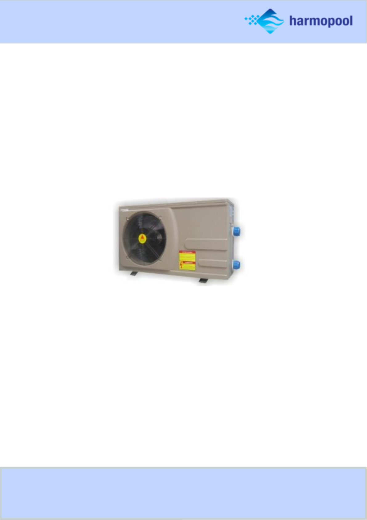
Swimming Pool Heat pump
Instruction manual – Harmo POWERPACK series
(Type ZVWX3103, ZVWX3113, ZVWX3123, ZVWX3128)

2
Table of contents
Introduction ................................................................................................................................................................... 3
Characteristics
.......................................................................................................................................................... 3
Safety instructions ......................................................................................................................................................... 3
Specifications ................................................................................................................................................................. 4
Installation ..................................................................................................................................................................... 5
Accessories needed for the installation .................................................................................................................... 5
Location ..................................................................................................................................................................... 5
Distance ..................................................................................................................................................................... 6
Installation of the pool system .................................................................................................................................. 7
Installation of the bypass .......................................................................................................................................... 7
Electrical wiring ......................................................................................................................................................... 8
Start-up procedure .................................................................................................................................................... 8
Condensation ............................................................................................................................................................ 8
Guidelines ...................................................................................................................................................................... 8
Water chemistry ........................................................................................................................................................ 8
Winter-ready ............................................................................................................................................................. 9
Spring start-up ........................................................................................................................................................... 9
Owner inspection ...................................................................................................................................................... 9
Display settings ............................................................................................................................................................ 10
Clock settings .......................................................................................................................................................... 11
Timer settings .......................................................................................................................................................... 11
Functions of the display............................................................................................................................................... 12
Current status.......................................................................................................................................................... 14
Maintenance ................................................................................................................................................................ 14
Appendix ...................................................................................................................................................................... 15

3
Introduction
Read the manual carefully before you open or maintain the heat pump. The manufacturer of this product will
not be held responsible for injuries or damage to the unit, as a result of improper installation, debugging or
unnecessary maintenance. It is essential that the instructions of this manual are followed at all times.
Qualified personnel must install the heat pump.
○ Only a qualified installer, center, personnel or an authorized dealer, should repair the heat pump.
○
Maintenance and operation must be carried out according to the recommended time and frequency, as
mentioned in this manual.
○
Use original standard spare parts only. Failure to comply with these recommendations will you’re your
warranty.
Characteristics
○
Durable: the heat exchanger is made of PVC & Titanium, which can withstand prolonged exposure to
water.
○ Easy operation: the heat pump is very easy to use: turn the heat pump on and set the desired water
temperature.
○ Silent operation:
the intelligent LCD display allows you to set the perfect temperature.
○ Low cost: the operational cost is very low compared to the high performance of this heat pump.
Safety instructions
○ Place the heat pump at a safe distance. Never place the pump within a radius of 350 cm from the pool.
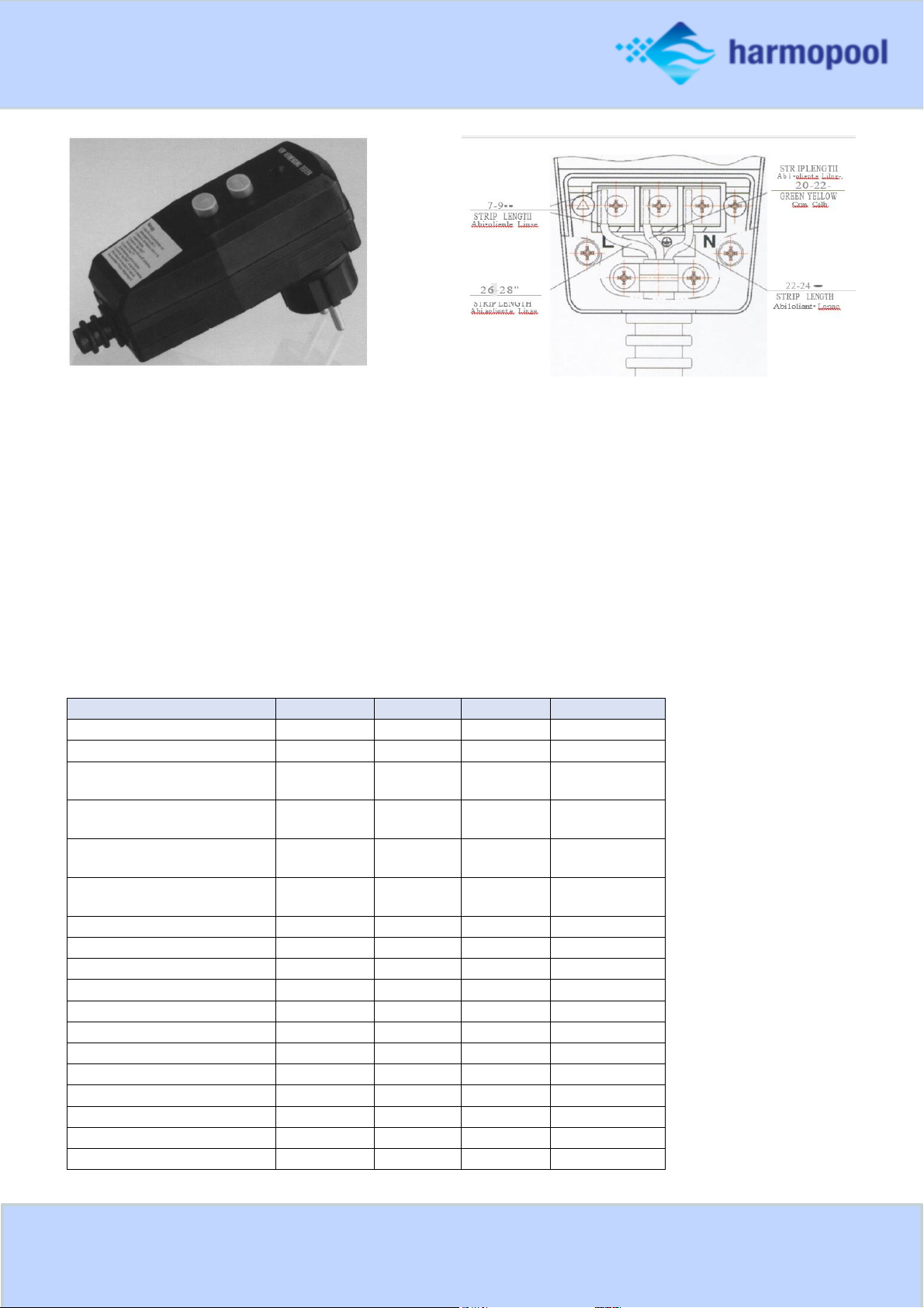
○ The heat pump can be mounted with an RCD safety plug.
○ Put the RDC plug directly and solely into an earthed socket. Never use an extension cord or similar.
○ Check the voltage on the plug to the power at the socket. Only use an earthed socket.
○ Always check that the safety plug is working properly to ensure safety. Never remove the safety plug.
○ Place
the pump and plug in a dry location. The heat pump is splash proof.
○ The failure to comply with these instructions could result in serious injuries.
○ Important!
Gas: Please verify the nameplate of the heat pump which mentions the gas. In case of R32 gas, measures for
explosion risk need to be taken: It is forbidden to hold an open flame (cigarette, lighter), in the vicinity of the
heat pump. It is forbidden to install the heat pump in the vicinity of a heat source.
4
Safety test
1. Use the wiring diagram in the manual.
2. Plug into the socket.
3. Press the RESET button. The indicator "ON" is highlighted.
4. Press the "TEST" button. The indicator "ON” will be turned off.
5. Press the RESET button in order to use the device. Do not use if above test fails.
Specifications
Product code:
ZVWX3103
ZVWX3113
ZVWX3123
ZVWX3128
Product type:
MONO
MONO
MONO
MONO
COP 27°T air 27°T water
5.8
6.0
5.7
5.0
Minimum outside
temperature
-10°
-10°
-10°
-10°
Heating Capacity (kW) 27°T
air 27°T water
7
12
14
18
Nominal power consumption
(A)
5,0
8.8
11
16
Nominal water flow rate
(m³ / h)
2 to 4
4 to 7
5 to 8
5 to 8
Heat exchanger
Titanium
Titanium
Titanium
Titanium
Connection (mm)
50
50
50
50
Control panel
Digital
Digital
Digital
Digital
Compressor (number)
1 1 1
1
Ventilators 1 1 1 1
dB
48
48
49
48
Weight (pump/packaging)
42/47
53/58
70/78
82/90
Compressor
Rotary
Rotary
Rotary
Scroll
Volt
230V
230V
230V
230V
Length ( pump/packaging )
105/117
105/117
110/126
110/126
Width ( pump/packaging )
37/42
37/42
45/50
45/50
Height ( pump/packaging )
62/65
62/65
72/75
72/75
5
Installation
Accessories needed for the installation
The factory only provides the heat pump. Other necessary items that could be mentioned in the illustrations are to
be provided by the user or installer.
Attention! Please follow the following steps when installing the heat pump:
○ The chemicals have to be added downstream of the heat pump.
○ It is recommended to install a bypass when the flow of the pool pump is more than 20% of the rated flow of
heat exchanger from the heat pump.
○ Install the heat pump on a solid foundation and use rubber below the heat pump to eliminate vibrations and
noise.
○ Installeer de warmtepomp op een solide basis en gebruik de dempende rubber om het geluid en de vibratie te
elimineren.
○ Keep the unit straight up at all times. When the unit has been tilted, it is required to wait 24 hours before re-
starting the heat pump.
○ The heat pump can be installed practically anywhere outdoors. If you wish to install it indoors, please contact
your supplier.
Location
The heat pump can be installed practically anywhere outdoors.
DO NOT
place the unit in a closed area with a limited air volume where the air discharged by the heat pump
will be re-circulated
DO NOT
put the unit next to bushes. This can block the air inlet. Such locations deny a continuous source of
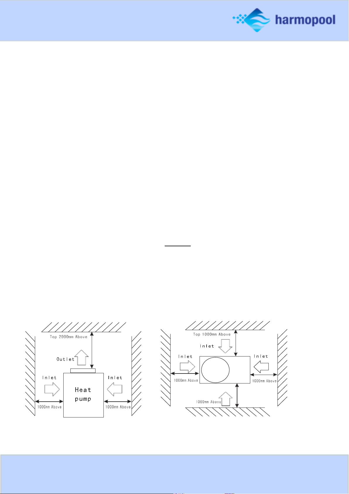
fresh air, which reduces the efficiency of the heat pump and can prevent adequate heat delivery. The picture
below shows the minimum required distances from each side of the heat pump.

6
Distance
Install the heat pump as close to the swimming pool as possible to minimize the loss of heat through the piping.
Put it on a solid base and place some rubber blocks under the heat pump to eliminate vibrations.
Normally, the heat pump is installed within a 7,5 meter radius of the pool. Heat loss is minimal up to distances of
30 meters. The heat loss per 30 meters is estimated at 0.6kw/hour for every 5˚C difference between the pool
water and surrounding of the pipe. This increases the lifespan around 3-5%.
Installation of the valve
The placement of the chlorinator, water balance equipment, and the placement of injectors of chemicals, are very
important aspects of the installation. All addition of chemicals have to be done downstream from the heat pump.
Failure to protect the heat pump unit from chemical damage is not covered by your warranty. A check-valve must
be installed between the heat pump and the chemical feeder to prevent back-siphoning of chemically saturated
water into the heat pump where it will damage the components.

7
Installation of the pool system
Installation of the bypass
With the bypass set correctly, your heat pump will deliver its best performance. The bypass has to be built as
shown below:
Setting the valves of the by-pass:
○
Install the bypass with all 3 valves entirely open
○
Slightly
close valve 1
○ Close
valve
3 about halfway to adjust the refrigerant pressure

8
Electrical wiring
Verify the local power supply and the operating voltage of the heat pump. It is recommended to use a separate
circuit breaker (slow type – D curve) for the heat pump together with the proper wiring characteristics. The current
to the heat pump should only be applied when the filter pump is running. For example, a relay controlled by the
filter pump could be used to activate the current to the heat pump. Connect the electrical supply to the junction
box inside the heat pump. All heat pumps require a single-phase connection. Earthing the heat pump is required to
protect you against electrical shocks caused by an eventual short circuit inside the heat pump.
The heat pump is not equipped with a flow switch or any other kind of water flow detection. Therefore, the heat
pump has to be wired electrically together with the filter pump to ensure water flow while the heat pump is
running.
Please consult the Appendix for more information
Start-up procedure
Start-up Procedure - after the installation is completed, you should follow these steps:
1. Turn on your filter pump. Check for water leaks and verify the flow to and from the pool.
2. Turn on the electrical power supply to the heat pump and turn the heat pump ON with the switch. The
heat pump will start after the time delay period has lapsed.
3. After running a few minutes, check whether the air leaving the heat pump is now cooler.
4. Allow the unit and pool pump to run 24 hours per day until desired pool water temperature is reached.
When the set temperature is reached, the unit just shuts off. The unit will now automatically restart (as
long as your pool pump is running) when the pool temperature drops more than 1 degree Celsius below
set temperature. Several days are needed to bring the temperature of your swimming pool water to its
required value.
Water flow switch - the unit is equipped with a flow switch that switches on when enough water has flowed
through the unit and vice versa.
Time delay - the unit is equipped with a 3-minute built-in delay to protect the control circuit components and
to eliminate restart cycling and contactor chatter. This time delay will automatically restart the unit
approximately 3 minutes after each circuit interruption. Even a brief power interruption will activate this delay
and prevent the unit from starting until the 3-minute countdown is completed.
Condensation
Since the Heat pump cools down the air about 8 - 12 °C, this causes condense on the fins of the evaporator. If the
relative humidity is very high, this could be as much as several liters an hour. Sometimes this condensation water
is misjudged as pool water and considered to be a leakage.
Guidelines
Water chemistry
Special care should be taken to keep the chemical balance of your swimming pool within limits:
pH 7,0 – 7,4
Free chlorine 0,5 – 1,2 mg/l
TAC 80 – 150 mg/l (10°F – 30°F)
Salt max 8 g/l

9
○ Failure to keep the swimming pool water between above limits will void the warranty
○ When the concentration of one or more products mentioned above becomes too high, irrevocable damage to
your heat pump may occur. Make sure that you always install water treatment equipment after the heat
pump.
○ When an automatic chemical feeder is installed, it must be installed downstream of the heat pump.
○ A check-valve must be installed between the heat pump and the chemical feeder to prevent back-siphoning of
chemically saturated water into the heat pump where it will damage the components.
Winter-ready
Failure to winterize the heat pump could cause damage to the heat pump and will void warranty.
In areas where freezing temperatures occur, you should protect your pump, filter and heat pump. Perform the
following steps to completely drain the heat pump:
1. Turn off the electrical power to the heat pump at the main breaker panel.
2. Shut off the water supply to the heat pump: close valves 2 and 3 on the by-pass completely.
3. Disconnect the water inlet and outlet and let the water drain from the heat pump.
4. Connect the inlet and outlet again to prevent dirt from entering the connections.
Spring start-up
If your heat pump has been made winter-ready, perform the following steps whilst starting the heat pump again in
spring:
1. Inspect the system for any debris or structural problems.
2. Connect the water inlet and outlet unions firmly.
3. Turn on the filter pump to supply water to the heat pump. Adjust the by-pass to allow water flow through
the heat pump.
4. Turn on the electrical power to the heat pump at the main panel.
Owner inspection
The POWERPACK heat pumps are designed and constructed to provide long performance life when installed and
operated properly under normal conditions. Periodic inspections are important to keep your heat pump running
safely and efficiently through the years. The following basic guidelines are suggested for your inspection:
1. Make sure the front of the unit is accessible for future service.
2. Keep the surrounding areas of the heat pump clear of all debris.
3. Keep all plants and bushes trimmed and away from the heat pump.
4. Keep lawn sprinkler heads from spraying on the heat pump to prevent corrosion and damage. Use a
deflector if needed.
5. If the heat pump is installed under a very sharp roof pitch or under a roof without a gutter, a gutter or
diverter should be fitted to prevent excessive water from pouring down onto the heat pump.
6. Do not use the heat pump if any part has been exposed to an excessive amount of water.
Immediately call a qualified professional technician to inspect the heat pump and replace any part of the
control system, which has been submerged.

10
The heat pump will produce condensation (water) operating. The heat pump base is designed to allow the
condensation to exit through the bottom drain port. The condensation will increase as the outdoor air humidity
level increases. Check the following at regular intervals to ensure proper condensate drainage:
1. Visually inspect and clear the bottom drain port of any debris that could clog the port.
2. Keep the air intake area and discharge area clear of debris so the airflow through the heat pump is not
restricted. The cooler discharge air should not accumulate and be drawn into the side air intake coils.
During normal operation, the heat pump produces ten to twenty liters of condensation per hour. If
condensation drainage is above this range during operation or if water continues to drain from the base
when the heat pump is not in operation for more than an hour, a leak in the internal plumbing may have
occurred. Call a qualified heat pump technician to investigate the problem.
A quick way to verify that the water running through the drain is condensation water is to shut off the unit and
keep the pool pump running. If the water stops running out of the base pan, it is condensation water.
Display settings
1.Under running status, press to adjust the temperature
2. Press " M"to choose the mode
Press "M “ again for cooling
Press "M “again for heating
3. Standby status:
Press "M" 5 seconds, get a sound “B” ,LCD display will show “0" “27”.Press “SET” to enter cooling
temp. setting, press to alter cooling temp. Press “SET” again to confirm.
Press "M again" "1 27" Press “SET” to enter heating temp. setting, press to alter heating temp.
Press “SET” again to confirm.
Press "M again" " "2 40" Press “SET” to enter defrosting time setting, press to alter defrosting time.
Press “SET” again to confirm.
Press "M" again "3" "-7" Press “SET” to enter defrosting temp. setting, press to alter defrosting temp.
Press “SET” again to confirm.
Press "M" again "4" "13 " Press “SET” to enter exit defrosting temp. setting, press to alter exit
defrosting temp.
Press “SET” again to confirm.
Press "M" again "5" "8 " Press “SET” to enter exit defrosting time setting, press to alter exit defrosting
time. Press “SET” again to confirm.
Press "M" again "6" "1 " Press “SET” to enter system quantity setting, press to alter system quantity.
Press “SET” again to confirm.
Press "M" again "7" "1 " Press “SET” to enter Automatic setting, press to alter. Press “SET” again to
confirm.

11
Press "M" again "8" "1 " Press “SET” to enter Mode setting, press to alter. Press “SET” again to
confirm.
Press "M" again "9" "0 " Press “SET” to enter water pump setting, press to alter. Press “SET” again
to confirm. Press "M" again "A" "40 " Press “SET” to enter return water temp. setting, press to
alter. Press “SET” again to confirm.
Press "M" again "b" "5 " Press “SET” to enter Overheat protection(heating mode) setting, press to
alter.
Press “SET” again to confirm.
Press "M" again "C" "35 " Press “SET” to enter Electronic expansion valve setting, press to alter.
Press “SET” again to confirm.
Press "M" again "D" "5 " Press “SET” to enter Overheat protection(cooling mode) setting, press to
alter.
Press “SET” again to confirm.
Press "M" again "E" "40 " Press “SET” to enter Max. temp. setting, press to alter. Press “SET” again to
confirm.
Press "M" again "F" "2 " Press “SET” to enter Split temp. setting, press to alter. Press “SET” again to
confirm.
Press "M" again "G" "-10 " Press “SET” to enter Ambient temp. protection setting, press to alter.
Press “SET” again to confirm.
Clock settings
Under running or standby status,Press “SET” for 5 seconds,get a sound “B”, press to alter hour, press
“SET”again to alter minute.Press “SET”again to confirm.
Timer settings
Under running or standby status, Press “ ” for 5 seconds, get a sound “B”, press to alter hour of timer
ON, Press “ ”again to alter minute of timer ON. Press “ ”again to alter timer OFF.

12
Functions of the display
o Under standby status, press M button 5s to enter Operation Parameter setting interface;" "
o Press"M"again to start setting (parameter from 00-D,see the Operation Parameter Table);
o Under parameter setting, press to set data;
o Please note no motion on the display for 10s,the LCD will display water-in/water out
temp.(under running)or ambient temp.(under standby status)
o Under running status, you can press M" ”5s to check current parameter, but you cannot
change the data of the parameter!
o Remarks: Standby status means the unit is connected with electricity but not running.
or

13

14
Current status
Under running status, press “M” 5 seconds to check the status of the unit. You can check waterin/water out temp, condenser temp and ambient temp, please note no motion on the display for
10s, the LCD will display water-in/water out temp/ (under running) or1ambient temp. (unit stops).
Maintenance
o Check the water supply to the unit often. Low water flow and air entering into the system
should be avoided, as this will diminish the units’ performance and reliability. You should clean
the pool filter regularly to avoid damage to the heat pump as a result of the dirty or clogged
filter.
o The area around the heat pump should be dry, clean and well ventilated. Clean the heat
exchanger regularly to maintain a good heat exchange and to save energy.
o Only a certified technician should service the operating pressure of the refrigerant system.
o Check the power supply and cable connection often. Should the unit begin to operate
abnormally, switch it off and contact a qualified technician.
o In winter, please discharge all water from the water pump and other systems to prevent
damage by freezing.
o Discharge the water at the bottom of the heat pump if the unit will not work for an extended
period of time. You should check the unit thoroughly and fill the system with water fully before
using it for the first time after a prolonged period of no usage.
Ambient temp.

15
Appendix
 Loading...