

Page 1

INSTALLATION INSTRUCTIONS
Harmony Nexus™ Equipment Management System
Fixed Suspension Tube with Fixed Pendant
(REV. A 01/08/13) 10023649
Page 2

A WORD FROM STERIS CORPORATION
This manual contains important information on the installation
procedures for the Fixed Suspension Tube with Fixed Pendant of the
Harmony Nexus™ Equipment Management System. Follow each
step of the installation instructions in the order presented. If you find
any indication of damage to the equipment (no matter how slight),
show it to your supervisor.
To properly install this unit, you will need the Equipment Drawings
(previously furnished), showing all utility service and space
requirements. If drawings cannot be located, replacement copies
may be obtained by writing, faxing or telephoning STERIS giving the
serial and model numbers of your equipment.
Once installed, equipment operation should be tested by a qualified
service technician prior to your usage of the equipment. Any
ancillary equipment (i.e., monitors, video recorders, etc.) that is to be
used with the Harmony Nexus Equipment Management System must
comply with all applicable medical equipment standards.
If STERIS supervision is desired for installing and starting up this
equipment, contact your local STERIS representative.
Indications for Use
Advisory
Harmony Nexus Equipment Management System (EMS) is inteded
for use in hospital facilities where there is a need for ready access to
medical gases, electrical power and audio/visual data services. The
EMS organizes surgical equipment such as endoscopy equipment,
laparoscopic equipment, cautery devices, insufflators, etc. Harmony
Nexus EMS units help hospitals to improve efficiency and safety, and
to maximize total room workflow by ergonomically centralizing all
surgical support equipment:
• As individual unit or in combination with the ceiling supply units
of the Harmony Nexus Equipment Management System
• For communicating and exchanging data, e.g., telephone,
nurse’s call button or computer networking
• For the ergonomic positioning of medical equipment during use
• For supplying medical equipment with electrical power and
medical gases
• To provide additional instrument trays, shelves and supports
The intended user for this equipment includes OR, ER/Trauma
Room, Ambulatory Surgery Center and ICU staff.
A listing of the safety precautions to be observed when installing and
testing this equipment can be found in S
PRECAUTIONS of these instructions. Do not begin installing this
equipment until you have become familiar with this information.
ECTION 1, SAFETY
IMPORTANT: Be sure to check the Occupational Health and Safety
Act, as well as local electric and plumbing codes, for any special
requirements that may pertain to installation of this unit.
©2013, STERIS Corporation. All rights reserved. Printed in U.S.A.
Introduction Installation Instructions 10023649
i
Page 3

Environmental
Conditions
Transport and Storage
NOTE: The following storage conditions apply for up to 15 weeks.
• Temperature: 13 to 158°F (–11 to +70°C)
• Relative Humidity: 10 to 75%
• Barometric Pressure: 0.5 to 1.05 atm STD atmospheric pressure
(500 to 1060 hPa)
• Store only in closed or covered spaces. After 15 weeks, the
values for the Operational Location Requirements (below) apply.
Operational Location Requirements
• The equipment is not suitable for operation in areas where there
is an explosion hazard.
• The Harmony Nexus Equipment Management System is not
suitable for use in the presence of a flammable anesthetic
mixture with air or with oxygen or nitrous oxide.
• The ambient temperature during operation must be kept
between 50 and 104°F (10 and 40°C)
• Relative humidity should stay within a range of 30 to 75%.
• Atmospheric pressure should stay within a range of 0.7 to 1.05
atm STD atmospheric pressure (700 to 1060 hPa).
ii
10023649 Installation Instructions Introduction
Page 4

The base language of this document is
ENGLISH. Any translations must be
made from the base language document.
STERIS Corporation,
Montgomery, Alabama is an
ISO 13485 certified facility.
STERIS Corporation
2720 Gunter Park East
Montgomery, AL 36109 • USA
Class 1 Equipment
Type B Equipment
Ordinary Equipment (enclosed equipment without
protection of ingress of water)
Equipment not suitable for use in the presence of a
flammable anesthetic mixture with air or oxygen or nitrous
oxide.
Suitable for continuous operation.
Canada Only:
Nonflammable medical gas pipeline systems shall comply
with CSA Z7396-1.
Electrical installations in healthcare facilities shall comply
with CSA C22.1 and CAN/CSA-Z32.
Anesthetic gas scavenging systems shall comply with
CSA Z7396.2.
Introduction Installation Instructions 10023649
iii
Page 5

TABLE OF CONTENTS
Section
Number Title Page
1 Safety Precautions................................................................................................................1-1
2 Installation Checklist............................................................................................................2-1
2.1 Tools Required.............................................................................................................................2-1
2.2 Hardware Required...................................................................................................................... 2-1
3 Verify Support Structure ......................................................................................................3-1
4 Overview of Mounting Method.............................................................................................4-1
5 Identifying Mounting Plate Type & Canopy Type...............................................................5-1
5.1 Mounting Plate Type ....................................................................................................................5-1
5.2 Canopy Types.............................................................................................................................. 5-1
5.3 Overview of Mounting Configurations..........................................................................................5-2
6 Mounting Details for the Various Configurations..............................................................6-1
6.1 Tandem Mount Unit – Hood Type Canopy................................................................................... 6-1
6.2 Tandem Mount Unit – Flush Mount Type Canopy ....................................................................... 6-1
6.3 Gas Riser Mounting ...... ... ... ... .... ...................................... .... ... ... ... ... ............................................6-1
7 Installation.............................................................................................................................7-1
7.1 Install Harmony Nexus Equipment Management System............................................................7-2
7.2 Install Bottom Column Cover ..................................................................................................... 7-15
7.3 Install Shelves............................................................................................................................7-17
8 Leveling Column...................................................................................................................8-1
8.1 Leveling Checklist ...................................... ... ............................................................................... 8-1
8.2 Leveling Column .............................................. ... .... ... ... ... ....................................... ... ... ...............8-2
9 Adjustments ..........................................................................................................................9-1
9.1 Adjust Column/Support Head Swivel Adjustment ........................................................................ 9-1
9.2 Adjust Friction Brakes – Column.................................................................................................. 9-2
10 Utility Connections .......................................................................................................... ...10-1
10.1 Final Connection of Gas Services.............................................................................................. 10-1
10.2 Final Connection of Electrical Services......................................................................................10-3
Table of Contents Installation Instructions 10023649
v
Page 6

TABLE OF CONTENTS (CONT’D)
Section
Number Title Page
11 Final Checkout ....................................................................................................................11-1
11.1 General ...................................................................................................................................... 11-1
11.2 Test Instrumentation Required...................................................................................................11-1
11.3 Functional Test.............. ... ... ... .... ...................................... .... ... ... ... ... .......................................... 11-1
11.4 Electrical Test............................................................................................................................. 11-1
11.5 Supply Lines Check ................................................................................................................... 11-2
11.6 Leak Test (not provided by STERIS) .........................................................................................11-2
vi
10023649 Installation Instructions Table of Contents
Page 7

LIST OF FIGURES
Figure Title Page
Figure 3-1. Above-Ceiling Support Structure......................................................................................................... 3-2
Figure 3-2. Ceiling Opening for Canopy Mount ..................................................................................................... 3-3
Figure 3-3. Ceiling Access Requirements.............................................................................................................. 3-4
Figure 4-1. Overview of Mounting Details.............................................................................................................. 4-1
Figure 5-1. Mounting Plate Types..........................................................................................................................5-1
Figure 5-2a. Canopy Types ...................................................................................................................................5-1
Figure 5-2b. Typical Mounting Configurations .......................................................................................................5-2
Figure 6-1. Gas Riser Detail .................................................................................................................................. 6-2
Figure 6-2. Plan View from Ceiling ........................................................................................................................6-4
Figure 9-1. Swivel Adjustments ............................................................................................................................. 9-1
Figure 9-2. Friction Brake Assembly...................................................................................................................... 9-2
Figure 10-1. Gas Riser (Detail View) ................................................................................................................... 10-2
Figure 10-2. 6 x 6 Junction Box Detail.................................................................................................................10-4
Figure 10-3. Position Junction Box Over Access Hole......................................................................................... 10-5
Figure 10-4. Position Plate Under Access Hole...................................................................................................10-5
Figure 10-5. Attach Divider .................................................................................................................................. 10-6
Figure 10-6. Secure Chassis Ground Wire..........................................................................................................10-7
Figure 10-7. Secure Metal Conduit to Junction Box ............................................................................................ 10-8
Figure 10-8. Wire Detail.......................................................................................................................................10-9
Table of Contents Installation Instructions 10023649
vii
Page 8

LIST OF TABLES
Table Title Page
Table 1-1. Definition of Symbols.............. ... ... ....................................... ... .... ... ... ... ...............................................1-3
Table 6-1. Gas Riser/Dust Cap Part Numbers ....................................................................................................6-3
Table 7-1. Column Capacity .......................................... ....................................................................................7-17
Table of Contents Installation Instructions 10023649
ix
Page 9

1
!
!
!
!
!
!
!
SAFETY PRECAUTIONS
The following Safety Precautions must be observed when operating or servicing the Harmony Nexus™ Equipment
Management System. WARNING indicates the potential for personal injury and CAUTION indicates the potential
for damage to equipment. For emphasis, certain Safety Precautions are repeated throughout the manual. It is
important to review ALL Safety Precautions before operating or servicing the unit.
Strictly following these Safety Precautions enhances the Customer’s ability to safely and effectively utilize the unit
and helps avoid improper maintenance methods which may damage the unit or render it unsafe. It is important to
understand that these Safety Precautions are not exhaustive; Customers are encouraged to develop their own
safety policies and procedures to enhance and complement these Safety Precautions.
WARNING – EXPLOSION HAZARD:
The ceiling mount system must not be installed where flammable gases or anesthesia are or will be
used. This equipment is not designed for use in a hazardous location as defined in National Fire
Protection Association (NFPA) Flammable Anesthetics Code.
WARNING – PERSONAL INJURY HAZARD:
1
After shipping frame and skid have been dismantled, unit can rotate freely. Do not lean against and/or
use mounted unit for support.
Ensure ceiling gas supply lines are depressurized before removing protecti ve caps.
Connecting electrical equipment to the multiple socket outlet (MSO) effectively leads to creating a
medical electrical (ME) system, and the result can be a reduced level of safety.
WARNING – ELECTRIC SHOCK AND BURN HAZARD:
Disconnect all utilities to the unit before installation. Do not install unless all utilities have been properly
locked out. Always follow OSHA lockout-tagout and electrical safety related work practice standards.
To avoid the risk of electric shock, this equipment must only be connected to a supply mains protective
earth.
WARNING – PERSONAL INJURY AND/OR EQUIPMENT DAMAGE HAZARD:
Repairs and adjustments to this equipment should be made only by fully qualified service personnel.
Maintenance performed by inexperienced, unqualified personnel or installation of unauthorized parts
could cause personal injury, invalidate the warranty or result in costly damage. Contact STERIS Service
Engineering representative regarding service options.
Safety Precautions Installation Instructions 10023649
1-1
Page 10

WARNING – PERSONAL INJURY AND/OR EQUIPMENT DAMAGE HAZARD (CONT’D):
!
!
!
!
!
!
!
!
!
!
Always lift the assembly of the Equipment Management System (EMS) where indicated by the "Lift Here"
label applied to the packaging. Failure to lift the assembly where indicated could cause the unit to fall
from the forks, causing equip ment damage or personal injury.
Verify air source supplying air to the pneumatic brake system. Lockout/tagout the air source for the
particular EMS unit be fore servicing.
Do not exceed maximum shelf load. Refer to Table 7-1.
The unit and shipping materials weigh approximately 1,000 lb (454 kg). To ensure safety, adequately
rated equipment must be used to move or lift unit.
Two people are required to install the shelf.
CAUTION – POSSIBLE EQUIPMENT DAMAGE:
Do not remove arm support shipping brack et s or shipping fr ame fr om skid. Set up of supply colu mn m ust
be conducted with protective packaging intact.
Carefully rotate support head when adjusting rotational stops. Rotating the support head completely
around (360°) will twist and kink gas lines and electrical wires located inside the column.
Care should be taken not to damage bolts when lifting main unit.
Be careful not to drop any hardware into the mouth of the distance tube.
Never set up supply column without the packaging protection.
1-2
10023649 Installation Instructions Safety Precautions
Page 11
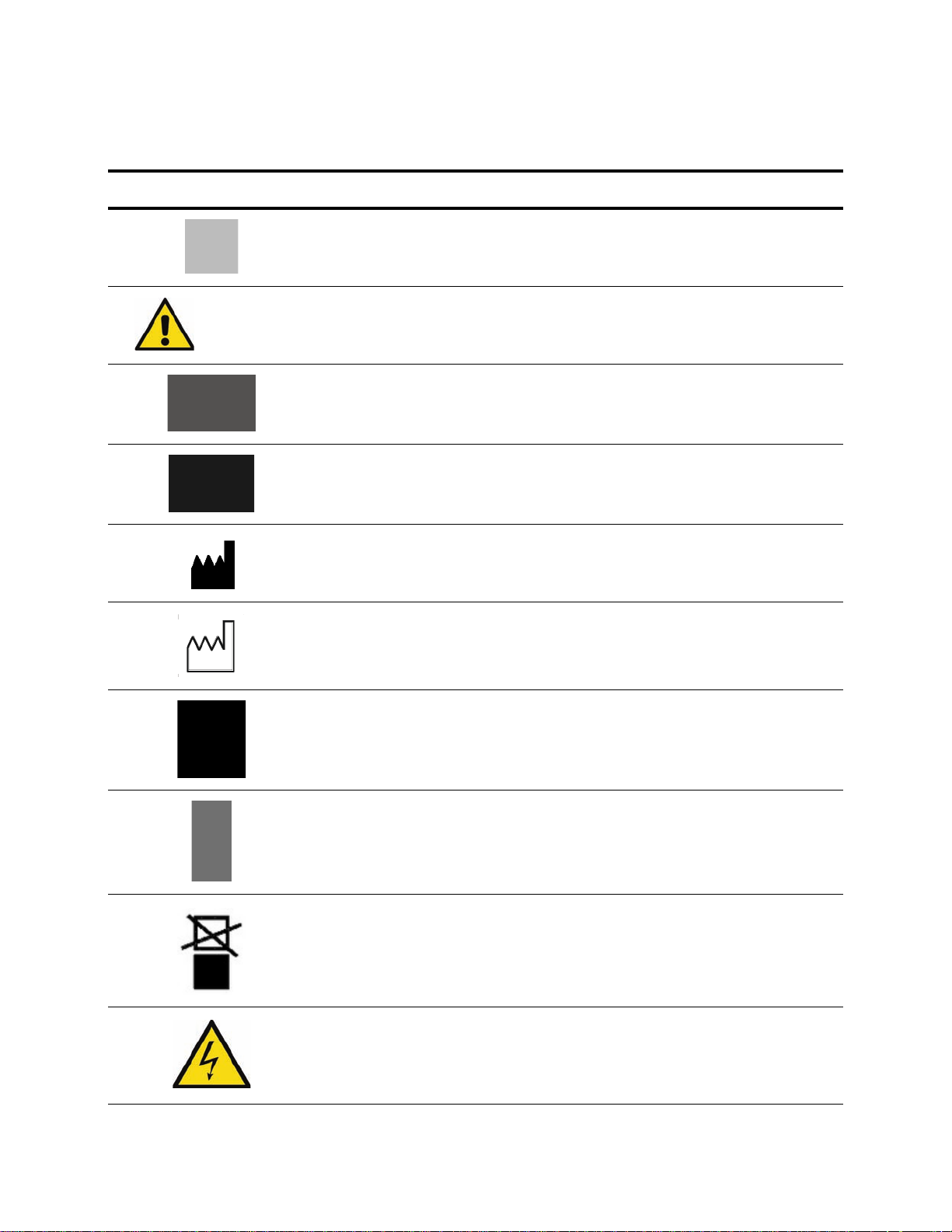
The following symbols may appear on the Harmony Nexus Equipment Management System and packaging:
Table 1-1. Definition of Symbols
Symbol Definition
Protective Earth (Ground)
Attention, consult manual for further instructions
or
Serial Number of Unit
Equipment or Reorder Number
Symbol indicating the legal manufacturer name and address
Symbol indicating the date of manufacture (yyyy/mm)
Keep dry
Fragile, handle with care
Do not stack
Symbol indicating high voltage
Safety Precautions Installation Instructions 10023649
1-3
Page 12

Table 1-1. Definition of Symbols (Continued)
Symbol Definition
V~ Voltage Rating of Unit, Alternating Current
A Amperage Rating of Unit
Hz Frequency Rating of Unit
1-4
10023649 Installation Instructions Safety Precautions
Page 13

INSTALLATION CHECKLIST
2
2.1 Tools Required
2.2 Hardware Required
• Lifting device (e.g., Genie® Lift™1) with minimum 600 lb (272 kg)
capacity. If Equipment Management System (EMS) unit is
greater than 600 lb (272 kg), then two lifting devices are
required.
• P764331-622, Lift, Material Genie, 350 lb (159 kg)
• P764331-944, Genie Superlift, 650 lb (295 kg)
• Spirit level or digital level (P764335-021, Digital Level)
• Open-end wrenches 19 mm, 24 mm and 30 mm
• Torque wrench with standard and metric sockets
• Metric Allen wrench set
• Multimeter capable of measuring volts and ohms
• Volumetric Pressure Gauge
®
• LOCTITE
0.5 mL pouch)
• Leak Detection Fluid
• Screwdrivers
The hardware listed below is referenced in these instructions. It is
required for proper installation of this equipment, and is provided by
STERIS unless otherwise noted.
242 (R005300-554 bottle, or 129377-290 single use
2
❑ 7/8-9 UNC x 16" long allthread ASTM A354 Grade BD steel alloy
(or SAE Grade 8), six required
❑ 7/8" flat washer, 24 required
❑ 7/8" lock washer, 12 required
❑ 7/8-9 UNC nuts, ASTM A354 grade BD (or SAE grade 8)
steel alloy, 48 required
❑ Structural framework (not provided by STERIS)
❑ Structural mounting plate (not provided by STERIS)
❑ Two 6.0" (152 mm) dia. access holes required in center of plate
❑ Support hangers (not provided by STERIS)
❑ 24 x 24" (610 x 610 mm) access panel (not provided by STERIS)
1. Genie® Lift™ is a registered trademark of Genie Industries, a Terex Company.
2. LOCTITE
Installation Checklist Installation Instructions 10023649
®
is a registered trademark of Henkel Corporation.
2-1
Page 14
!
!
VERIFY SUPPORT STRUCTURE
Before installing the Harmony Nexus™ Equipment Management
WARNING – PERSONAL INJURY
AND/OR EQUIPMENT DAMAGE
HAZARD: Unit and shipping
materials weigh approximately
1000 lb (454 kg). To ensure safety,
adequately rated equipment must
be used to move or lift unit.
CAUTION – POSSIBLE
EQUIPMENT DAMAGE: Care
should be taken not to damage
bolts when lifting main unit.
System:
1. Verify Customer’s ceiling mount meets dimensions as specified
in Figure 3-1 and Figure 3-2.
2. Verify that hardware is on site (either in the room where the EMS
unit is to be installed or hanging from the structural mounting
plate). If hardware cannot be located, contact STERIS.
3
Verify Support Structure Installation Instructions 10023649
3-1
Page 15
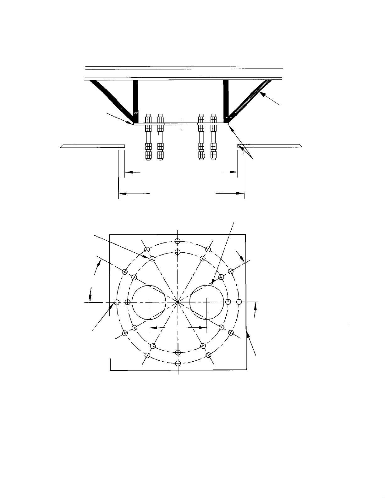
Structural Mounting Plate
( May Be Provided by
STERIS)
Structural Bracing
(Not provided by STERIS)
23" (584 mm) Square Rough
Opening in Finished Ceiling
23-5/8" (600 mm) Square Required
Area for Canopy Hood
IMPORTANT:
Ensure that plate is installed with
edges parallel to 23" (584 mm) square
rough opening in finished ceiling.
Single Mount Unit Bolt Hole Pattern
Shown on 18.500 B.C.
30° Typ.
Tandem Mount Unit Bolt Hole
Pattern
15/16" Through, 12 Equally
Spaced as Shown on 22.500 B.C.
6.0" Dia. Through Holes, two Required
(Provided by STERIS)
30° Typ.
Structural Mounting Plate
(Provided by STERIS)
10.63
(270 mm)
3-2
10023649 Installation Instructions Verify Support Structure
Figure 3-1. Above-Ceiling Support Structure
Page 16
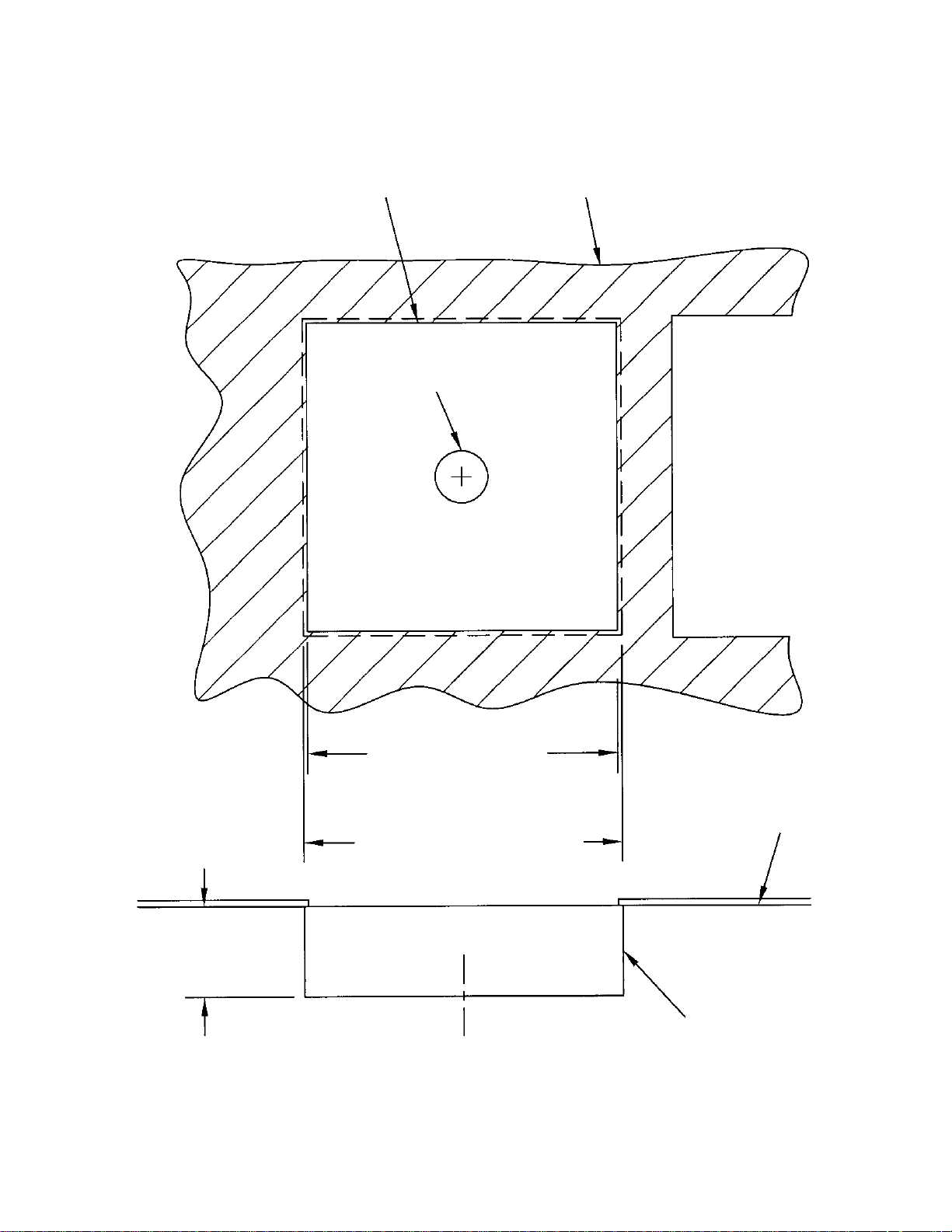
Ref. Hole in Finished Ceiling
Finished Ceiling
Hole in Canopy Hood
Access Opening 24 x 24"
(610 x 610 mm) for Access
to Above Ceiling Hardware
23" (584 mm) Square Rough
Opening in Finished Ceiling
23-5/8" (600 mm) Square Required Area
for Canopy Hood
3.56" (90.4 mm) Ref.
Finished Ceiling
Canopy Hood
(Provided by STERIS)
Verify Support Structure Installation Instructions 10023649
Figure 3-2. Ceiling Opening for Canopy Mount
3-3
Page 17

Figure 3-3. Ceiling Access Requirements
3-4
10023649 Installation Instructions Verify Support Structure
Page 18

OVERVIEW OF MOUNTING METHOD
4
Figure 4-1. Overview of Mounting Details
Overview of Mounting Method Installation Instructions 10023649
4-1
Page 19

A
B
IDENTIFYING MOUNTING PLATE TYPE & CANOPY TYPE
5.1 Mounting Plate
5
Single mount plate (see Figure 5-1).
Typ e
Figure 5-1. Mounting Plate Types
5.2 Canopy Types
There are two types of canopies
a. Canopy Hood – for a single mount unit
b. Flush Mount – for a single mount unit
Figure 5-2a. Canopy Types
Identifying Bearing/Ceiling Plate Type & Canopy Type Installation Instructions 10023649
5-1
Page 20

Figure 5-2b. Typical Mounting Configurations
Flush Mount
Type Canopy
Hood Type Canopy Mount
5.3 Overview of
Mounting
Configurations
Harmony Nexus EMS mounting configurations are made up from
various combinations of the two types of mounting plates and the two
canopy types.
1. Single mount unit
• Mounting plate
• Hood type canopy
2. Single mount unit
• Mounting plate
• Flush mount type canopy
5-2
10023649 Installation Instructions Identifying Bearing/Ceiling Plate Type & Canopy Type
Page 21

MOUNTING DETAILS FOR THE VARIOUS CONFIGURATIONS
6.1 Gas Riser Mounting
6
• The Gas Riser Mounting Bracket must be installed on the
structural plate by using 1/4-20 UNC screws provided.
• 6" (152 mm) clearance is required above structural mounting
plate for gas supply hook-up.
Mounting Details for the Various Configurations Installation Instructions 10023649
6-1
Page 22

CAUTION – POSSIBLE
!
Gas Riser Bracket
(Provided by STERIS)
Gas Riser Bracket
(Provided by STERIS)
Male D.I.S.S. Fitting
w/Cap
Copper Tube
GAS RISER
(Provided by STERIS)
Structural Plate
(Provided by STERIS)
Support Hangers
(Not Provided by
STERIS)
Gas Riser Bracket
(Provided by STERIS)
Flexible Gas Hose
(Provided by STERIS)
6"
(152 mm)
16"
(406 mm)
6"
(152 mm)
Fire Wrap – If Required
(Not Provided by STERIS)
Finished Ceiling
Gas Riser
(Provided by STERIS)
Support Hanger
(Not Provided by STERIS)
Support
Structure
Structural Plate
(Provided by STERIS)
Gas Supply from
Zone Valve
EQUIPMENT DAMAGE: Do not
remove arm support shipping
brackets or shipping frame from
skid. Set up supply column must
be conducted with protective
packaging intact.
Figure 6-1. Gas Riser Detail
6-2
10023649 Installation Instructions Mounting Details for the Various Configurations
Page 23

Table 6-1. Gas Riser/Dust Cap Part Numbers
Gas Riser Part Number Gas Dust Cap Part Number
136812-668 WAGD 150824-808
136812-669 Oxygen 150824-807
136812-670 Vacuum 150824-806
136812-671 Med Air 150824-806
136812-672 Nitrogen 150824-806
136812-673 Carbon Dioxide 150824-806
136812-674 Nitrous Oxide 150824-806
Mounting Details for the Various Configurations Installation Instructions 10023649
6-3
Page 24

Ceiling Access Panel Located Between Gas
Riser and PES Vacuum Pump Motor for
Greatest Accessibility to Utility Connections
Access Panel
24 x 24" (610 x 610 mm)
1 Required
(Not Provided by STERIS)
PES Vacuum
Pump Motor
Gas Riser (Provided by
STERIS)
2' (1 m) Max.
Gas Riser Bracket
(Provided by STERIS)
Support Structure
Figure 6-2. Plan View from Ceiling
6-4
10023649 Installation Instructions Mounting Details for the Various Configurations
Page 25

Harmony Nexus
Equipment Management System
INSTALLATION
Personnel Required: (Two)
7
Personal Protective Equipment Required:
• Safety Goggles or Safety Glasses
• Gloves • Steel-Toe Shoes • Hard Hat
Special Tools:
• Lifting device (e.g., Genie® Lift™1) with minimum 600 lb (272 kg) capacity. If Equipment Management System
(EMS) unit is greater than 600 lb (272 kg), then two lifting devices are required.
• P764331-622, Lift, Material Genie, 350 lb (159 kg) capacity
• P764331-944, Genie Superlift, 650 lb (259 kg) capacity
• Spirit level or digital level (P764335-021, Digital Level)
• Open-end wrenches 19 mm, 24 mm and 30 mm
• Torque wrench with standard and metric sockets
• Metric Allen wrench set
• Multimeter capable of measuring volts and ohms
• Volumetric Pressure Gauge
®
• LOCTITE
• Leak Detection Fluid
• Screwdrivers
242 (R005300-554 bottle, or 129377-290 single use 0.5 mL pouch)
2
1. Genie® Lift™ is a registered trademark of Genie Industries, a Terex Company.
2. LOCTITE
Installation Installation Instructions 10023649
®
is a registered trademark of Henkel Corporation.
7-1
Page 26

7.1 Install Harmony
STEP
1
Mounting Hardware and
Accessories Package
(May Consist of
Multiple Packages)
Nexus Equipment
Management System
Step 1: Remove separate packages, miscellaneous mounting hardward and/or unattached
7-2
10023649 Installation Instructions Installation
accessories from shipping container.
NOTE: Do not remove brackets/supports that hold the unit to the skid.
NOTE: Verify all audio/visual cabling is present per sales order.
Page 27

STEP
2
NOTE: Dimensions
are in inches.
Step 2: Install intermediate plate and canopy mounting plate to support structure.
7-3
Installation Installation Instructions 10023649
Page 28

STEP
3
7/8" All Thread
7/8" Nut (x2)
7/8" Flat Washer
Step 3: Install All Thread, 7/8" nuts and 7/8" washers around the structure plate.
7-4
10023649 Installation Instructions Installation
Page 29

STEP
4
7/8" Nut
7/8" Flat Washer
7/8" Lock Washer
Lower Mounting
Plate Hardware
Step 4: Install All Thread, 7/8" nuts, 7/8" flat washers and 7/8" lock washers surrounding the
bottom of structure plate.
• Install lower 7/8" nuts and 7/8" flat washers such that the top of mount plate is 6-8"
(152-203 mm) below bottom of structure plate.
Installation Installation Instructions 10023649
7-5
Page 30

STEP
5
7/8" Flat Washer
7/8" Lock Washer
7/8" Regular Nut
M5 Flat Washer
M5 Lock Washer
M5 Screw
NOTE: Slots in canopy
mounting plate are arc
shaped to allow for
canopy alignment with
ceiling opening.
Step 5: Raise mount plate up to the lower mounting hardware.
• Install 7/8" nuts, flat washers and lock washers on bottom of mount plate.
• Level mount plate using three or four nuts.
• When mounting plate is level, tighten remaining nuts.
• Torque all 7/8" hardware to 80 ft•lb (356 N•m).
7-6
10023649 Installation Instructions Installation
Page 31

STEP
6
M16 Regular Nut
M16 Flat Washer
M16 Lock Washer
M16 Regular Nut
Step 6: Thread M16 All Thread into threaded holes in mounting plate.
• Install M16 lock washers and M16 regular nuts in order to secure M16 All Thread to
mounting plate.
• Install M16 nuts and flat washers such that top of mounting plate is 3.25" (83 mm) from
top of drop tube weldment.
Installation Installation Instructions 10023649
7-7
Page 32

STEP
7
Step 7: On unit, arrange hoses and cables so they do not cross one another.
7-8
10023649 Installation Instructions Installation
Page 33

STEP
8
Flange
Shipping Frame
Shipping Skid
Important: Lifting Equipment Must Be Rated
for at Least 600 lb (272 kg). Two Lifts Are
Required If EMS Unit Is Heaver Than 600 lb
(272 kg).
Step 8: Use lifting device to raise unit, including shipping frame and skid, to a height where all
mounting bolts can be aligned with holes in unit upper mount. Align bolts with upper
mount, then raise unit.
• Thread cables and hoses through center of ceiling plate.
• Raise unit fully.
Installation Installation Instructions 10023649
7-9
Page 34

STEP
9
Cotter Pin
M16 Lock Washer
M16 Regular Nut
Step 9: Install M16 lock washers and M16 regular nuts in order to secure M16 drop tube
weldment.
• Install cotter pins on bottom of All Thread (four places).
7-10
10023649 Installation Instructions Installation
Page 35

STEP
10
Step 10: Dismantle shipping crate and lower skid.
• Verify distance tube flange is secured with lock washers, nuts and cotter pins.
• Level column with nuts surrounding distance tube flange.
• Level drop tube weldment as described in Section 8.
• After leveling procedure, tighten all mounting hardware to 80 ft•lb (356 N•m).
7-11
Installation Installation Instructions 10023649
Page 36

STEP
11
M5 Threaded Rod
M5 Flat Washer
M5 Jam Nut
Step 11: Install six M5 threaded rods into canopy mounting plate for canopy cover mounting.
• Install M5 flat washer and jam nut at approximately 1-1/2" (38 mm) from upper end of
threaded rod.
7-12
10023649 Installation Instructions Installation
Page 37

STEP
12
M5 Jam Nut
M5 Adapter Nut
Measure 3.19" from Ceiling
Step 12: Install adapter nuts into threaded rods approximately 1/2" to 5/8".
• Lock adapter nut in place with M5 jam nut.
NOTE: For hood type canopy, adapter should hang 3.19" below ceiling. For flush mount type
canopy, adapter should hang 0.44" below ceiling.
• After verifying clearance, use upper M5 jam nut to lock threaded rods in position.
Installation Installation Instructions 10023649
7-13
Page 38

STEP
13
Canopy Seal
M5 Flat Washer
M5 Lock Washer
M5 Screw
M5 Lock Washer
M5 Screw
Step 13: Place two halves of canopy hood around bearing and connect them with four sets of M5
hardware (screw, flat washer, lock washer).
• Thread canopy seal onto upper surface of canopy wall.
• Raise canopy hood and insert M5 screws through hood into adapter nuts on M5
threaded rods installed previously.
• Tighten screws.
7-14
10023649 Installation Instructions Installation
Page 39

7.2 Install Bottom
STEP
1
Threaded Rods
(x2)
STEP
2
Washer
Nut
Column Cover
Step 1: Insert two flat rods with threaded rods into column such that threaded rods drop out of
column.
Step 2: Attach bracket with washers and nuts.
7-15
Installation Installation Instructions 10023649
Page 40

STEP
3
Screws (x4)
Step 3: Place cover onto bottom and secure with four screws.
7-16
10023649 Installation Instructions Installation
Page 41

7.3 Install Shelves
STEP
1
Mounting Clamps
Washers (x8)
Screws (x8)
!
WARNING – PERSONAL INJURY AND/OR EQUIPMENT DAMAGE HAZARD: Two people are
required to install the shelf.
Step 1: Lift shelf to desired height. Use lifting device if necessary.
• Position mounting clamps on opposite side of rails.
• Secure mounting clamps with washers (x8) and screws (x8).
Table 7-1. Column Capacity
45" (1143 mm), 35" (889 mm) and 25" (635 mm) Length Column Weight Capacity without Accessories
Number of Shelves Average Weight Load Per Shelf
5 38 lb (17 kg)
4 56 lb (25 kg)
3 85 lb (39 kg)
Do not exceed maximum shelf load of 85 lb (39 kg).
The maximum loading for column is the average of the loaded weight per shelf times number of shelves. Do not exceed
maximum weight of 85 lb (39 kg) on a single shelf. Maximum column load is 350 lb (159 kg) which includes 32 lb (14.5 kg)
for each shelf plus weight of equipment.
7-17
Installation Installation Instructions 10023649
Page 42

STEP
2
Step 2: Installation complete.
7-18
10023649 Installation Instructions Installation
Page 43

Harmony Nexus
Equipment Management System
LEVELING COLUMN
8.1 Leveling Checklist
8
Personnel Required: (Two)
Personal Protective Equipment Required:
• Safety Goggles or Glasses
•Gloves
• Steel-Toe Shoes
•Hard Hat
Parts Required:
• Shelf/Shelves
Special Tools:
• Genie
®
Lift™
1
• Ladder (8’ [2 m])
• Spirit Level or Digital Level (
P764335-021, Digital Level)
• Weight Scale
• 24 mm wrench
1. Genie® Lift™ is a registered trademark of Genie Industries, a Terex Company.
8-1
Leveling Column Installation Instructions 10023649
Page 44

8.2 Leveling Column
STEP
1
Step 1: Place digital level on column.
• Adjust nuts until column is level.
8-2
10023649 Installation Instructions Leveling Column
Page 45

Setscrew
Fixed Stop
ADJUSTMENTS
9
9.1 Adjust Column/
Support Head Swivel
Adjustment
See Figure 9-1.
NOTE: The swiveling range of the supply column is 320° and can be
limited up to 50° (45° increment).
1. To set swiveling range, loosen two screws in ring above top
column cover and lift up to allow access to bearing.
NOTE: Perimeter of bearing has 14 M8 threaded holes. A M8
socket head cap setscrew with washer is screwed into one of the
holes as a stop.
Figure 9-1. Swivel Adjustments
2. To limit swiveling range further, insert an additional screw
accordingly or relocate existing second stop screw (supplied
with product) to the desired location.
3. Reinsert top column cover onto supply column.
Adjustments Installation Instructions 10023649
9-1
Page 46

9.2 Adjust Friction Brakes – Column
See Figure 9-2.
Loosen two screws in ring above top column cover and lift up to
access brake.
NOTE: There are setscrews that adjust the friction brake. Adjust
middle screw first. If braking is still insufficient, adjust outer
setscrews.
Figure 9-2. Friction Brake Assembly
9-2
10023649 Installation Instructions Adjustments
Page 47

!
UTILITY CONNECTIONS
10
10.1 Final Connection of Gas Services
WARNING–PERSONAL
INJURY HAZARD: Ensure
ceiling gas supply lines are
depressurized before
removing protective caps.
1. Locate gas lines with Diameter Index Safety System (D.I.S.S.)
connectors protruding from the bearing plate of the Harmony
Nexus Equipment Management System.
2. Match gas type coding connectors of Harmony Nexus EMS with
those projecting downward from ceiling plate.
3. Connect gas lines:
a. Remove plastic bag and protective caps from ceiling supply
lines on connectors of Harmony Nexus EMS.
NOTE: DISS con nectors are size inde xed to prevent inte rconnection
of incorrect gas lines. If connectors do not ma te easily, do not force.
Check gas type coding, stamped on side of fitting, before p roceedin g.
b. Connect gas lines of Harmony Nexus EMS to ceiling supply
lines. Tighten fittings securely and test for leaks.
Normal Settings
• Nitrogen – Supply gauge 160 psi ± 2% accuracy
• Instrument air: 125 psi ± 2% accuracy
Gauge Information
• Range: 1-300 psi
• Accuracy: 0-100 ± 3%
100-200 ± 2%
200-300 ± 3%
4. Once all gas lines have been connected, set gas supply lines
away from any moving parts on or around the bearing plate and
junction boxes.
Utility Connections Installation Instructions 10023649
10-1
Page 48

Support Hangers
(Not Provided by STERIS)
Gas Riser Bracket
(Provided by STERIS)
Structural Plate
(Provided by STERIS)
6"
(152 mm)
Flexible Gas Hose
(Provided by STERIS)
Hose
Latch Rough-In
Trim
Latch Valve
Copper Tube
Male D.I.S.S. Fitting w/Cap
DETAIL – Gas Riser
(or Pipette)
16"
(406 mm)
6"
(152 mm)
Gas Riser Bracket
Figure 10-1. Gas Riser (Detail View)
10-2
10023649 Installation Instructions Utility Connections
Page 49

10.2 Final Connection
!
of Electrical Services
WARNING – ELECTRIC
SHOCK AND BURN HAZARD:
• Disconnect all utilities to the
unit before installation. Do not
install unless all utilities have
been properly locked out.
Always follow OSHA lockouttagout and electrical safety
related work practice
standards.
• To avoid the risk of electric
shock, this equipment must
only be connected to a supply
mains protective earth.
NOTE: Qualification:
• Electrical connection of the EMS system may only be performed
by a qualified electrician.
• Verify OR room is equipped with an isolation transformer.
• Please observe all applicable safety precautions. Review
ECTION 1, SAFETY PRECAUTIONS.
S
• Prewired circuits are contained in flexible conduits.
• The number of circuits and how they are divided is dependent
upon each individual user’s requirements.
• The circuits and conductors are identified, specified and listed
on the equipment data plate.
NOTE: Construction Detail: When wire stripping is required, the strip
length should be 8mm (5/16”). Str ay wir e st ra n ds a r e n ot pe r mit te d t o
be outside the crimp nuts. See Figure 10-8.
Utility Connections Installation Instructions 10023649
10-3
Page 50

Figure 10-2. 6 x 6 Junction Box Detail
1. Locate hardware kit P/N P129387-619 (provided by STERIS)
consisting of:
P093933-105 –Junction Box –Bottomless (6 x 6"), Qty. 1
P124290-106 –Screw 1/4"-20 UNC x 0.5" long, Qty. 8
P150824-544 –Lock Washer 1/4", Qty. 8
P093933-104 –Divider –Junction Box, Qty. 1
P093933-098 –Plate, Junction Box – Bottom, Qty. 1
2. Locate junction box –bottomless 6 x 6” (152 x 152 mm).
3. Position junction box over one of the two 6” (152 mm) dia.
access holes on top surface of structural plate holes. See Figure
10-3.
10-4
10023649 Installation Instructions Utility Connections
Page 51

Figure 10-3. Position Junction Box Over Access Hole
4. Secure junction box using two screws 1/4”-20 UNC x 0.5” long.
5. Locate junction box bottom plate.
6. Position plate under the same 6” (152 mm) dia. access hole on
the bottom surface of structural plate holes. See Figure 10-4.
Figure 10-4. Position Plate Under Access Hole
7. Secure small plate to bottom surface of large structural plate
using four screws 1/4”-20 UNC x 0.5” long by inserting screws
into existing tapped holes in structural plate. See Figure 10-3
8. Attach divider (if required) by using #8-32 UNC x 3/8 screws
(provided by STERIS). See Figure 10-4.
Utility Connections Installation Instructions 10023649
10-5
Page 52

Figure 10-5. Attach Divider
Connect Duplex/Simplex Circuits
9. Knock out one (of 10 provided) 7/8" dia. access holes in junction
box bottom plate.
10. Carefully route electrical conduit up to bottom plate and insert
stranded conductors through the 7/8" dia. hole.
11. Secure (bulkhead mount) flexible conduit connector(provided by
STERIS) to bottom plate using plastic nut (provided by STERIS).
12. Secure green chassis ground wire (running external to black
flexible conduit) using 1/4" green ground screw and 1/4" star
washer (provided by STERIS) to bottom surface of Customer
support structure plate. See Figure 10-6.
13. Use crimp nuts (provided by STERIS) to securely connect each
circuit to power supply.
14. Locate Customer supplied dedicated ground wire and run wire
to ground screw on structural plate. See Figure 10-6.
10-6
10023649 Installation Instructions Utility Connections
Page 53

Figure 10-6. Secure Chassis Ground Wire
15. Verify resistance between ground screw and junction boxes
does not exceed 0.1 Ohm.
16. Run a continuity test on all electrical connections.
17. Run an insulation test per conduit.
18. Replace access panel.
19. Turn electrical supply ON.
20. Verify all circuits are operating properly by measuring output
voltages.
21. Turn electrical supply OFF.
NOTE: Customer must bring power via Customer supplied metal
conduit to junction box (provided by STERIS)
a. Knock out the 7/8" dia. access holes in the side of junction
box. See Figure 10-2 and Figure 10-7.
b. Secure Customer supplied metal conduit to junction box.
Utility Connections Installation Instructions 10023649
10-7
Page 54

Figure 10-7. Secure Metal Conduit to Junction Box
!
Important: Verify all electrical power is OFF before making final
connection. Review S
WARNING – ELECTRIC SHOCK AND BURN HAZARD:
• Disconnect all utilities to the unit before installation. Do not
install unless all utilities have been properly locked out.
Always follow OSHA lockout-tagout and electrical safety
related work practice standards.
• To avoid the risk of electric shock, this equipment must only
be connected to a supply mains protective earth.
NOTE: Stranded conductors installed by Customer must be filled with
wire end connector sleeves or via use of a crimp nut.
NOTE: A terminal block is not provided by STERIS.
c. Connect power supply lines using Customer supplied onsite
circuit diagram and in conjunction with STERIS circuit
diagram. See Figure 10-8.
d. Use crimp nuts to securely connect circuit to above ceiling
electrical supply.
ECTION 1, SAFETY PRECAUTIONS.
10-8
10023649 Installation Instructions Utility Connections
Page 55

Figure 10-8. Wire Detail
Utility Connections Installation Instructions 10023649
10-9
Page 56

!
FINAL CHECKOUT
11
11.1 General
WARNING – PERSONAL INJURY
AND/OR EQUIPMENT DAMAGE
HAZARD: Repairs and
adjustments to this equipment
should be made only by fully
qualified service personnel.
Maintenance performed by
inexperienced, unqualified
personnel or installation of
unauthorized parts could cause
personal injury, invalidate the
warranty, or result in costly
damage. Contact your STERIS
Engineering Service
representative regarding service
options.
11.2 Test
Instrumentation
Required
Every unit must be tested and inspected according to this procedure
whenever a part is adjusted, repaired or replaced. Items which do
not comply to test procedures must be corrected or retested.
Important: Complete and mail in the Pre-In-service Checkout Card –
P764331-894, to begin warranty period. Contact STERIS.
• Voltmeter
• Ohmmeter
• Calibrated volumetric pressure test gauge –
must read 0 to 200 psig (0 to 1,379 KpA)
11.3 Functional Test
11.4 Electrical Test
Final Checkout Installation Instructions 10023649
1. Compressed air (if applicable) may be contaminated. Verify
availability of nitrogen or industrial air.
2. Verify electrical supplies are connected to unit.
3. Verify rotational stops are set to prevent support head and
accessories from striking walls or other equipment.
1. Measure voltage at each electrical receptacle. Measured
voltage should be equal to voltage supplied to unit.
2. Check each grounding pin for impedance (0.1 ohms maximum).
11-1
Page 57

11.5 Supply Lines Check
1. Check gases, medical air and compressed air pressures
supplied to unit. Refer to equipment drawing for recommended
pressures.
2. Check correct gases are supplied to proper corresponding
outlets.
3. Inspect all lines for chafing or kinking. Damaged lines must be
replaced.
4. Using leak detection fluid, check all line connections for leaks.
NOTE: NFPA certification and/or verification of gas supply line s is not
by STERIS.
11.6 Leak Test (not
provided by STERIS)
Leak test, using clean, oil-free, dry Nitrogen, for all gas lines (during
test procedure) in accordance with applicable codes.
11-2
10023649 Installation Instructions Final Checkout
 Loading...