

Harmony 9002D Servicing Manual
SERVICING MANUAL
9002D

SERVICE MANUAL AND PARTS LIST
TO CHANGE
THE FACE PLATE UNIT...............................................................................................1
THE BACK COVER UNIT.............................................................................................2
THE FRONT COVER UNIT ..........................................................................................3
THE SIDE COVER UNIT..............................................................................................4
THE MACHINE BASE ..................................................................................................5
THE MACHINE SOCKET .............................................................................................6
TO ADJUST
THE NEEDLE HEIGHT.................................................................................................7
THE PRESSER BAR HEIGHT .....................................................................................8
THE FEED DOG HEIGHT ............................................................................................9
THE TIMING OF THE NEEDLE AND THE FEED DOG.............................................10
THE TIMING OF THE NEEDLE AND THE UPPER KNIFE........................................ 11
THE HEIGHT OF THE LOWER LOOPER..................................................................12
THE CLEARANCE BETWEEN THE NEEDLES AND THE LOWER
LOOPER/NEEDLE GUARDS...................................................................... 13-15
THE CLEARANCE BETWEEN THE NEEDLES AND
THE FIXED NEEDLE GUARD ..........................................................................16
THE POSITION OF THE CHAINING FINGER...........................................................17
THE POSITION OF THE UPPER LOOPER...............................................................18
THE TIMING OF THE NEEDLE AND THE LOWER LOOPER ..................................19
THE TIMING OF THE UPPER AND THE LOWER LOOPERS..................................20
THE CLEARANCE BETWEEN THE LOOPERS ........................................................21
THE CLEARANCE BETWEEN THE NEEDLE AND THE UPPER LOOPER.............22
THE POSITION OF THE KNIVES..............................................................................23
THE POSITION OF THE LOWER LOOPER THREAD GUIDE ..................................24
THE STITCH LENGTH...............................................................................................25
THE THREAD TENSION DIALS ................................................................................26
PARTS LIST................................................................................................................... 27-37
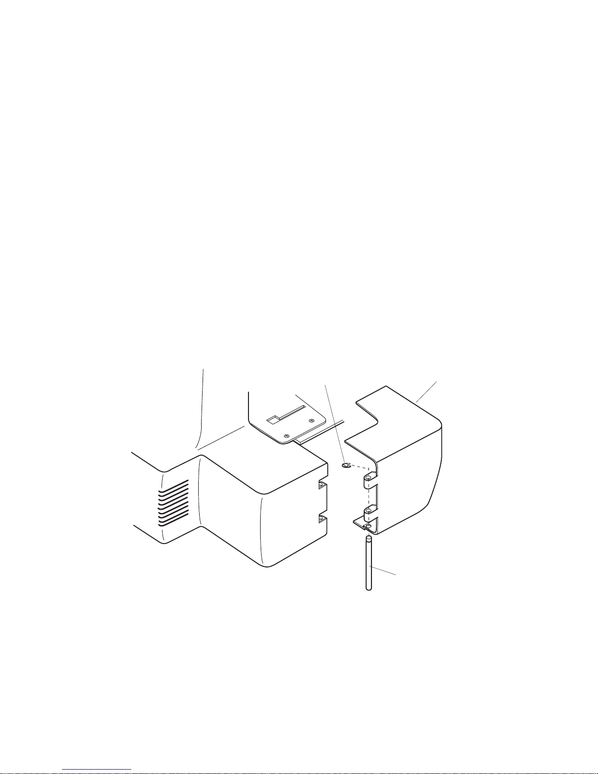
TO CHANGE THE FACE PLATE UNIT
To remove:
1. Loosen setscrew A and remove the face plate unit.
To attach:
2. Fit the U-groove of the face plate between setscrew A and set plate, put the rib of face
plate into the front cover unit and back cover unit and tighten setscrew.
Setscrew A
Face plate unit
U-groove
Set plate
Back cover unit
Rib
Front cover unit
1
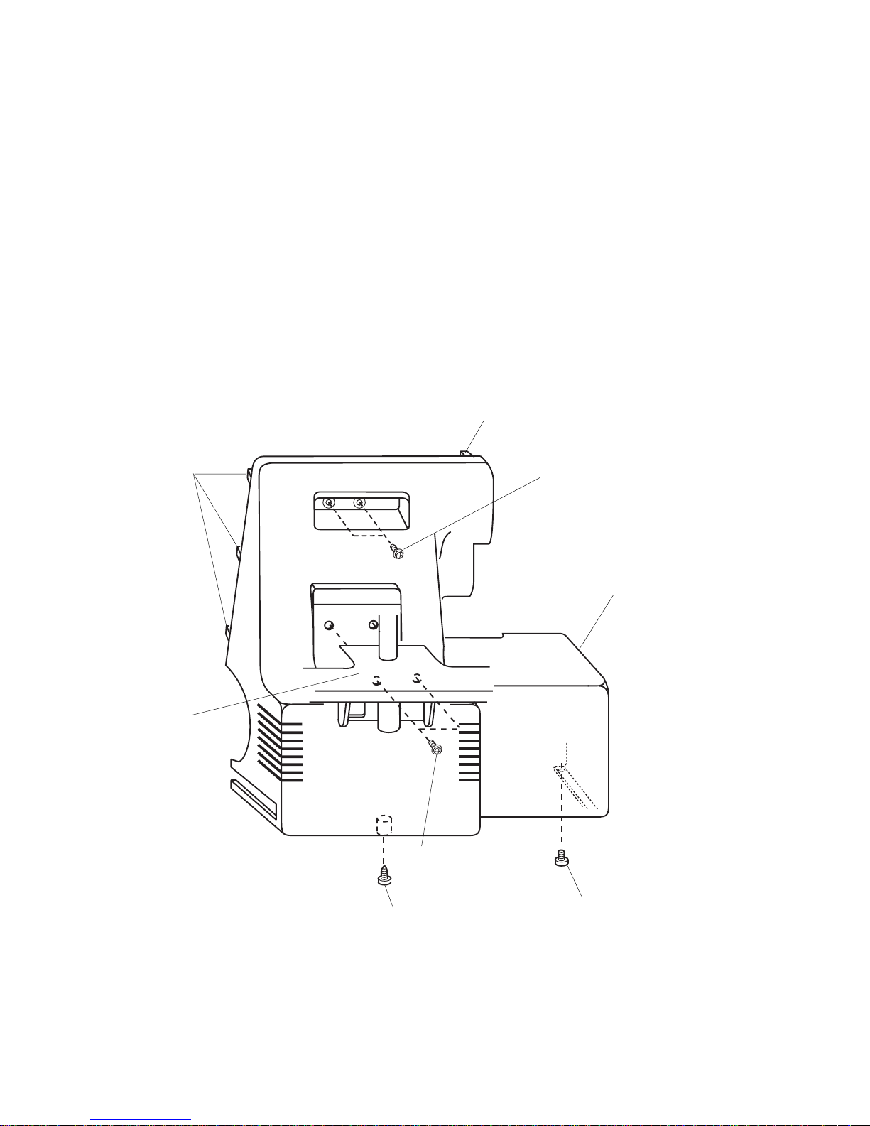
TO CHANGE THE BACK COVER UNIT
To remove:
1. Remove setscrews A and the spool stand.
2. Remove setscrews B,C and D.
3. Remove the back cover unit.
To attach:
4. Put the ribs of back cover into the front cover unit and tighten setscrews B, C and D.
5. Attach the spool stand with setscrew A.
Back cover unit
Setscrew B
Setscrew C
Set screw A
Setscrew D
Rib
Rib
Spool stand
2
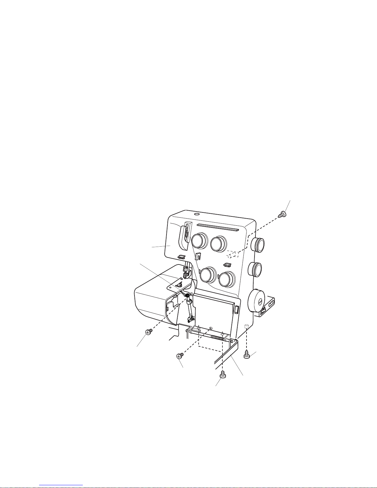
TO CHANGE THE FRONT COVER UNIT
To remove:
1. Remove setscrews A and the looper cover unit.
2. Remove the face plate unit and the back cover unit.
3. Turn the hand wheel toward you with your hand, and set the upper looper at its lowest position,
and remove setscrews B, C, D,E and the front cover unit.
To attach:
4. Attach the front cover unit with setscrews B, C, D and E.
5. Attach the looper cover unit with setscrew A.
6. Attach the back cover unit and face plate unit.
Setscrew C
Setscrew D
Upper looper should be set
at its lowest position
Front cover unit
Looper cover unit
Setscrew A
Setscrew E
Setscrew B
3
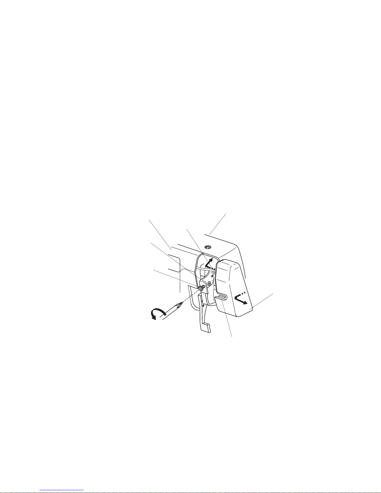
TO CHANGE THE SIDE COVER UNIT
To remove:
1. Open the side cover unit. Remove the snap ring E-3 and push down the shaft.
To attach:
2.Attach the side cover unit and insert the shaft and attach the snap ring.
Side cover unit
Snap ring E-3
Shaft
4
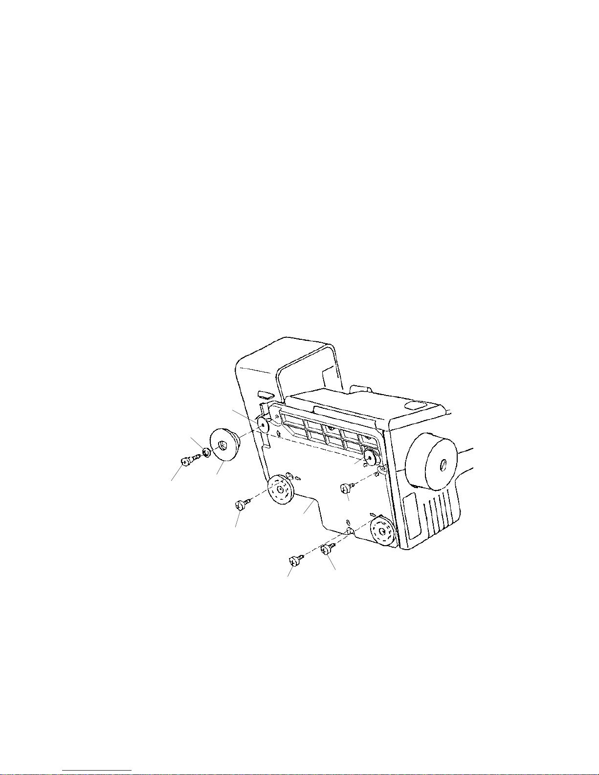
TO CHANGE THE MACHINE BASE
To remove:
1. Remove setscrews A, B, C, D and two hinge screws E, and remove two base cushions F
and washers.
2. Remove the machine base.
NOTE: Do not remove another two base cushions.
To attach:
3. Attach the machine base unit, and tighten setscrews A, B, C and D.
4. Attach the two base cushions F, washers, and tighten hinge screws E.
Washer (thick)
Washer
Base
cushion F
Hinge screw E
Setscrew D
Setscrew C
Setscrew B
Machine base
Setscrew A
Washer (thin)
5
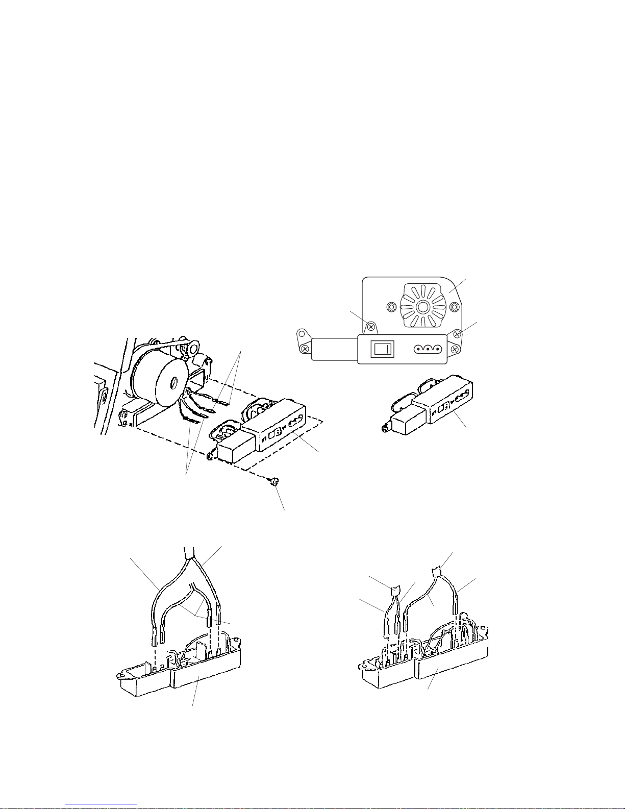
TO CHANGE THE MACHINE SOCKET
To remove:
1. Remove the back cover unit.
2. Remove setscrews (A, B) and the machine socket unit from the motor fixing plate.
3. Remove two setscrews C, and pull out the cord connectors.
To attach:
4. Insert the cord connectors as shown below.
5. Attach the machine socket, and tighten two setscrews C.
6. Attach the machine socket unit on the motor fixing plate and tighten setscrews (A, B).
7. Attach the back cover unit.
To motor
To lamp socket
Setscrews C
Machine socket
for 220 - 240V
Machine socket
for 120V
Lamp socket lead cord
For 220 - 240V Area
Lamp socket lead cord
Motor lead cord
(Blue)
(Brown)
Motor lead cord
For 120V
Lamp socket lead cord
(Brown)
(Blue)
Setscrews B
Setscrews A
Motor fixing plate
6
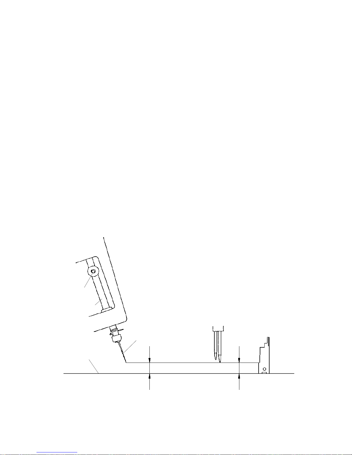
TO ADJUST THE NEEDLE HEIGHT
Correct Setting:
The distance between the tip of needle on the right and the surface of needle plate should be 11.6 to
12.2 mm when the needle bar is at the highest position.
To adjust:
1. Remove the looper cover unit, face plate unit, back cover unit and front cover unit.
2. Turn the handwheel toward you with your hand, and set the needle bar at the highest position.
3. Loosen setscrew A to adjust the height, and tighten setscrew A after the adjustment is done.
4. Turn the handwheel toward you one cycle, and recheck the needle bar height.
5. Attach the front cover unit, looper cover unit, back cover unit and face plate unit.
Setscrew A
Needle bar
Surface of needle plate
Needle #14
11.6 to 12.2 mm
11.6 mm
O.L G05
7
 Loading...