

Page 1
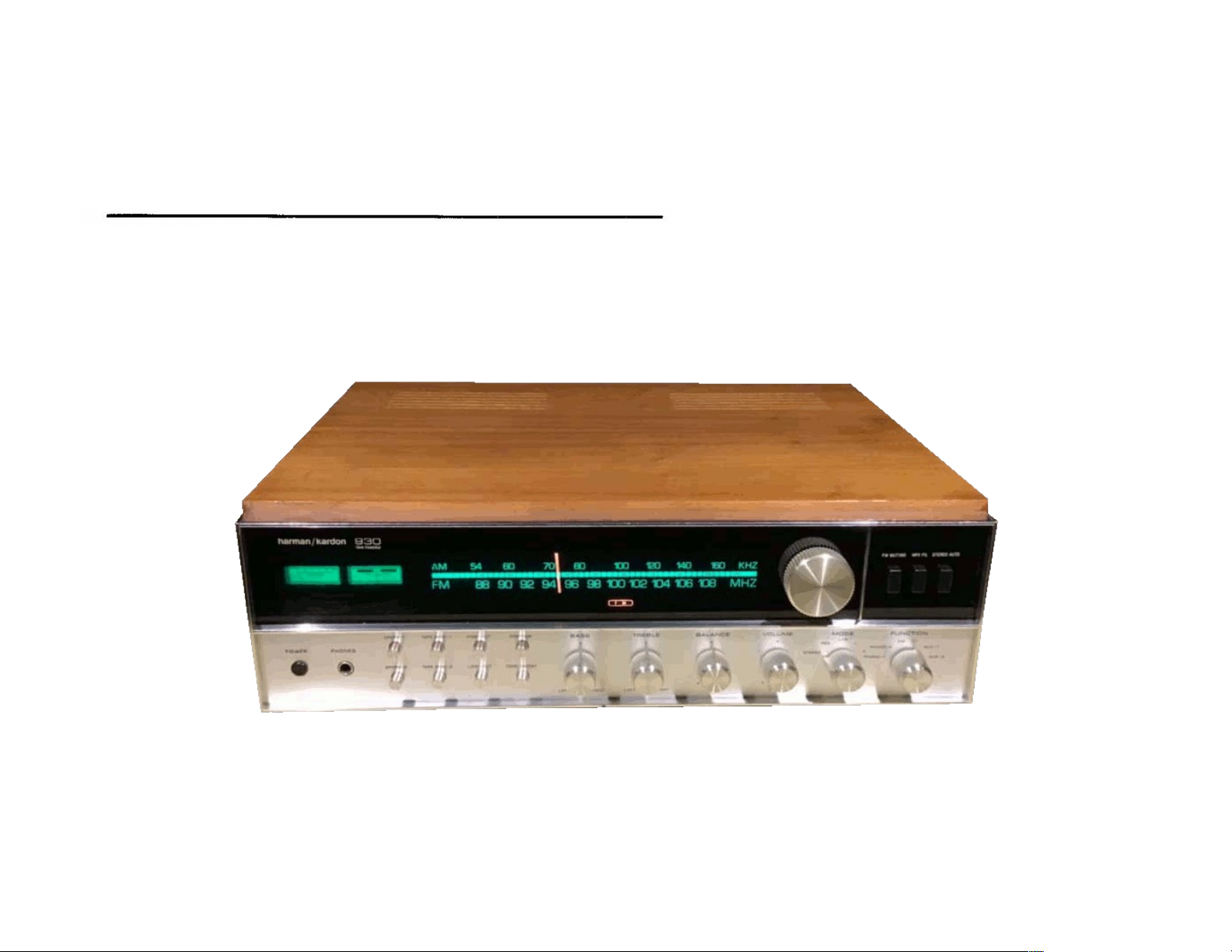
The Harman-Kardon
Model 930
AM/FM/Stereo FM
Solid State Receiver
harman/kardon
THE MUSIC COMPANY
Instruction Manual
Page 2

INTRODUCTION
With your purchase of the HARMAN-KARDON 930 receiver, you have en
tered a new era in high fidelity. The pages which follow describe the features
and operation of the receiver. We urge that you read them carefully before pro
ceeding to put the receiver into operation.
You now are the owner of an instrument unique in conception, design and
manufacture. For example, the two separate power supplies of the 930 (one for
each channel) guarantees flawless performance regardless of how much power
the amplifiers are called on to deliver. Each channel has its own regulated volt
ages to permit a response to full RMS power output without being affected by
the other channels. This closely regulated power supply results in cleaner and
more transparent sound.
The 930 is also the proud heir of the HARMAN-KARDON trademark — ultra
wideband frequency which reproduces sound beyond the limits of human hearing.
This provides extra realism to the range you actually hear.
There are but examples of what is in store for you, your family and friends
when you put the 930 to use,
Read this manual first . . . and then go on to en[oy many full years of genu
ine listening pleasure.
Page 3

WARRANTY and SERVICE POLICY
POLICY
We warrant each unit to be free from defects in material and workmanship
under normal use and service, and in accordance with the conditions set forth
below. Should a defect occur within the period specified, and provided that the
unit is returned to either HARMAN-KARDON or an authorized HARMAN-KARDON
warranty station, transportation prepaid, and which our examination shall
disclose to our satisfaction to be defective, we will, for a period of two (2) years
from date of purchase, either replace or repair and install any defective parts
of the stereo receiver free of charge.
EXCEPTIONS
This warranty does not include any obligation as to:
a) repair or replacement of the accessory wooden enclosure due to damage
incurred after initial delivery.
b) transportation charges to and from the factory or an authorized warranty
station.
REGISTRATION:
To obtain service under the terms of this policy, it is necessary for you to
retain your ORIGINAL BILL of SALE, The enclosed registration card will NOT
be considered proof of purchase.
In the event your equipment requires service during the warranty period, only
presentation of your original bill of safe to either a factory-authorized repair
agency or the factory, itself, will insure your rights under the policy, as outlined
in this manual.
This warranty is not applicable to any instrument which shall have been repaired
or altered in any way so as, in our judgment, to affect its stability or reliability
or has been subject to neglect, misuse, abuse, negligence, or accident; or which
has had the serial number altered, effaced or removed. Neither shall this warranty
apply to any instrument which has been connected other than In accordance with
Instructions furnished by us.
SERVICE
HARMAN-KARDON has a special customer service division to answer all ques
tions pertinent to the installation and operation of your unit. Please feel free to
write to us at any time and we shall endeavor to offer prompt and complete
advice.
If your problem cannot be resolved through our combined efforts, we may wish
to refer you to a local authorized repair agency or we may prefer to authorize
the return of your unit to the factory. In the event it must be returned, an authori
zation form and proper packing instructions will be forwarded to you. This
authorization form, together with the warranty registration number, MUST BE
RETURNED with your unit,
UNDER NO CIRCUMSTANCES SHOULD YOUR UNIT BE SHIPPED TO THE FAC
TORY WITHOUT PRIOR AUTHORIZATION.
This warranty is in lieu of all other warranties, expressed or implied, and of all
other obligations or liabilities on our part, and we neither assume nor authorize
any representative or other person to assume for us any other liability in con*
nection with the sale of this instrument.
Page 4

INSTALLATION PROCEDURE
VENTILATION
Although your new Receiver rarely develops high heat, it is still recommend
ed that you leave the back of the cabinet open. If this is not possible, provide
several large holes or slots as low down and as high up in the cabinet back
as possible. As an alternative, holes may be provided in the sides, bottom or
top of the cabinet. Remember that really effective ventilation requires provision
for cool air to enter at the bottom and hot air to leave at the top. A minimum
clearance of two (2) inches should be allowed on each side and in the rear,
between the chassis and the cabinet, and three (3) inches are required above it.
Isolate any accessories which might interfere with ventilation. For example,
do not drape plastic or rubber covered interconnecting cable over the equip
ment.
POWER REQUIREMENTS
Connect the AC line cord to any outlet furnishing 117 volts, 50/Ó0 cycle
AC current. The voltage may vary between 105 and 1 25 volts. Two auxiliary AC
power outlets are provided on the rear panel of your receiver, one being alive
at all times and the other being live only when the power switch is ON. Any
accessory equipment (tape recorder, phonograph record player, etc.) may be
connected to these receptacles and if connected to the SWITCHED receptacle,
this equipment will be controlled by the ON/OFF POWER switch.
FUSING
A fuse is a safety device used to protect the receiver against possible
damage due to overload, short circuits, and excess current. This receiver em
ploys three fuses for protection. The AC fuse, labeled 3À-3AG is used to pro
tect the entire system. The other two speaker fuses, also 3A-3AG, are used to
prevent damage to the output stage of your receiver.
The output of your receiver has been designed to operate with a MAXI
MUM of 3 amperes of current in each channel. Under certain conditions, it is
possible to draw more than 3 amperes through the output stage which would. In
turn, blow the speaker fuses. This could be caused by using multiple speaker
systems where the total impedance falls below 4 ohms. Whenever you plan to
operate more than two speakers simultaneously, make absolutely sure that their
total load impedance WILL NOT fall below 4 ohms.
In the event of fuse failure, replace ONLY with the same fuse type used.
NEVER replace with a fuse of a higher rating. To do so will NOT protect
your receiver and could result in severe damage to it which will not be covered
under the warranty policy.
SPEAKER PHASING
When more than one speaker is used in a music reproducing system, the
speakers must be connected in a manner which will allow them to work together.
Both left and right speakers must operate in perfect unison, moving back and
forth together. If the speakers are moving in opposite directions, the result will
be diminished bass response and decreased realism of sound. When this occurs,
the speakers are said to be out of phase. Checking for proper phase and cor
recting, if required, is quite simple.
1. After connecting your speakers, place the stereo receiver in the L & R
or monophonic mode of operation,
2. Play a record, tape, or FM broadcast which has a single speaking or
singing voice, or a solo instrument.
3. The voice or instrument should appear to be coming from an area
directly between the two speakers. If the speakers are out of phase, the sound
will appear to be coming from the two individual speakers.
4. If you determine that the speakers are out of phase, simply disconnect
the leads from only one of the speakers and reverse them. The system will then
be in phase.
This completes your speaker connections. Your receiver is a solid state
device which does not contain audio output transformers. It is therefore not
necessary to match the impedance of your speakers to the receiver. Your unit
will perform perfectly with any speaker which has an impedance of 4, 8 or
16 ohms.
Page 5
Your two speakers should be identical, if possible, to obtain optimum
results. Experts agree that a perfectly matched system offers the best stereo
phonic reproduction. The speakers should be placed along the same wall ap
proximately 8 to 10 feet apart depending upon room size and furniture place
ment, It may be necessary to experiment with speaker placement until best
results are obtained.
Use any type of wire to connect your speakers to your receiver. Lamp cord
zip cord is excellent and may be easily dressed around the molding for an
inconspicuous and neat installation. Do not drive the staples or tacks through the
center of the wire for this may short out the two sections and will decrease the
overall volume or short out the speakers entirely. It is permissible to use approxi
mately 50 feet of speaker connecting wire for each speaker without loss of
volume. CONNECT SPEAKERS WITH CARE. AVOID SHORTS — THE RECEIVER HAS
BEEN DESIGNED TO PREVENT DAMAGE FROM ACCIDENTAL SHORTING; HOW
EVER, REPETITIVE SHORTING CAN DAMAGE TRANSISTORS.
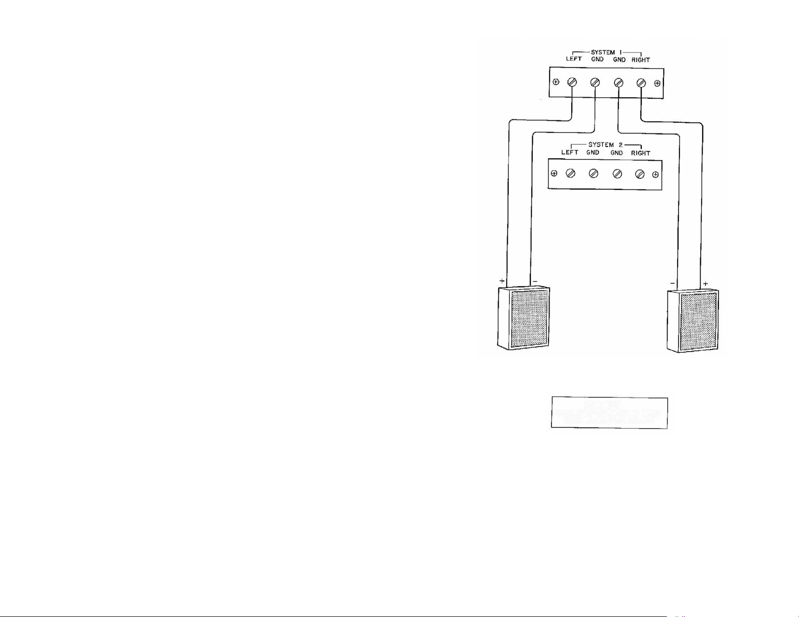
1. Connect one length of lamp cord to the left speaker. This is the
speaker on your left as you face the speakers.
2. Attach the other end of the lamp cord to the terminals marked SYSTEM
1 LEFT located on the rear of the receiver.
3. Similarly connect another length of lamp cord to your right speaker.
4. Attach the other end of the lamp cord to the terminals marked SYSTEM
1 RIGHT.
5. Your receiver is now connected for stereo operation and is operative
when the SPKR-l switch on the front panel is in the ON position.
SYSTEM 1
CAUTION
CONNECT SPEAKERS WITH CARE-
AVOfO ACCIDENTAL SHORTS
Page 6
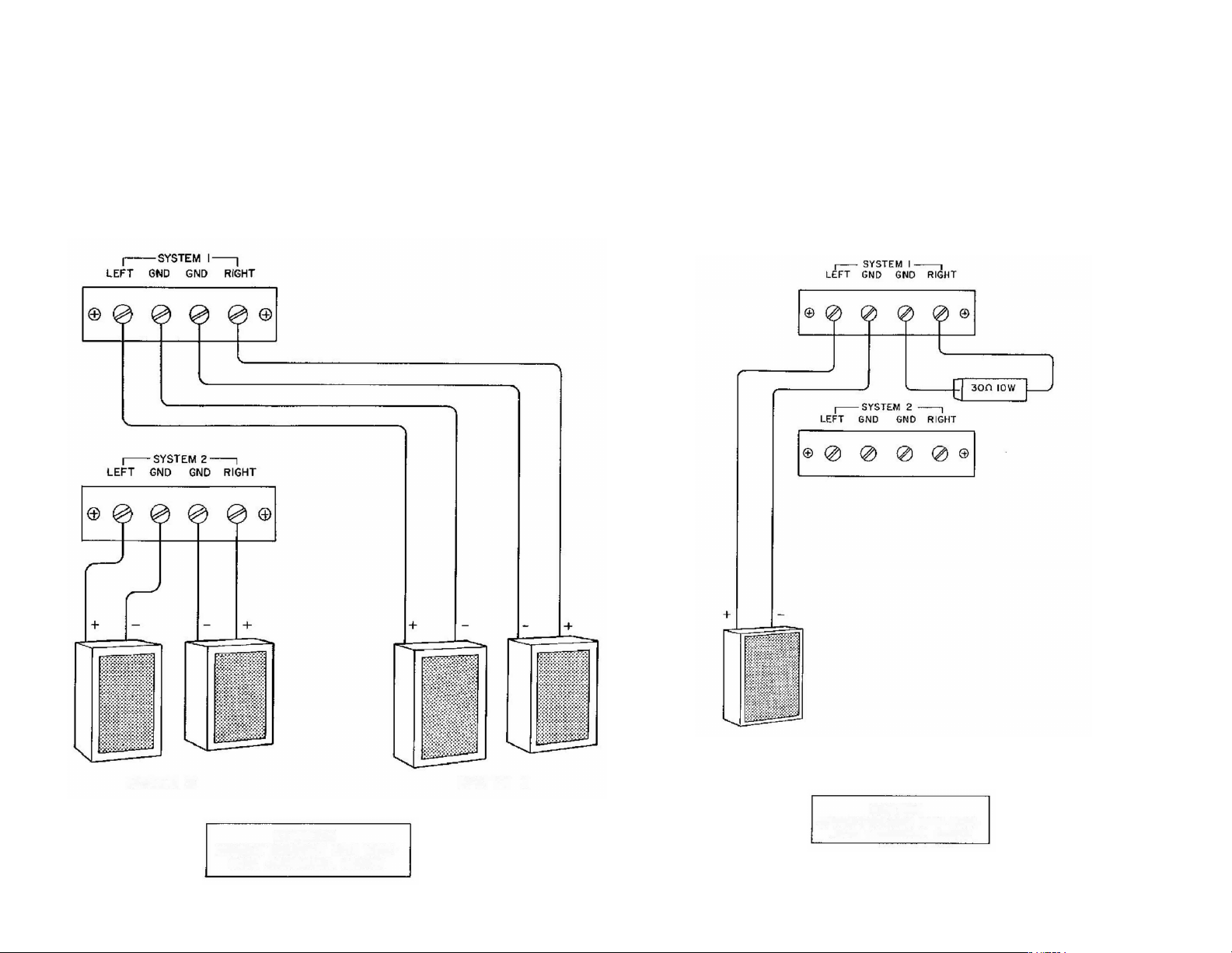
CONNECTING THE SPEAKERS FOR STEREO OPERATION
(2 SYSTEMS)
1, Connect all four speakers for two system operation as shown in Dia
gram.
2. You may now select either system 1, or system 2 by the use of the
speaker selector'switch located on the left side of the front panel of your
receiver.
If your receiver is to be used monophonically and stereo is to be added
at a later date, it is essential that both speaker output terminals are terminated
info a proper load to prevent damage to the output stage of the receiver. Refer
to Diagram or proper installation of the loading resistor.
At no time should the output terminals be paralleled for monophonic
__ __ _ __ _ __ _
i.*__ _ _ _i
SYSTEM 2
CONNECT SPEAKERS WITH CARE-
CAUTION
AVOID ACCIDENTAL SHORTS
SYSTEM 1
SYSTEM 1
CAUTION
CONNECT SPEAKER WITH CARE-
AVOID ACCIDENTAL SHORTS
Page 7
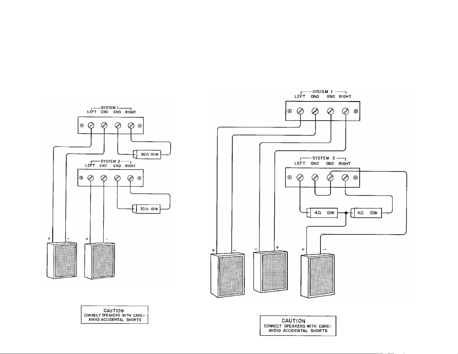
If your receiver is to be used monophonically and stereo is to be added
at a later date, if is essential that both speaker output terminals are terminated
into a proper load to prevent damage to the output stage of the receiver. Refer
to Diagram for proper installation of the loading resistors.
At no time should the output terminals be paralleled for monophonic
operation I
CONNECTING THE SPEAKER FOR STEREOPHONIC
OPERATION (SYSTEM 1} AND MONOPHONIC
OPERATION (SYSTEM 2}
SYSTEM I SYSTEM 2
SYSTEM 1
SYSTEM 2
Page 8

INPUT CONNECTIONS
CONNECTING the FM ANTENNA
The antenna input has been designed to accept either a 300 ohm balanced
transmission line (300 ohm twin lead) or a 75 ohm unbalanced co-axial cable
transmission line.
Due to the exceptionally high sensitivity of your receiver, a 48" wire
is sufficient for all but the most difficult locations. When using the 48" antenna,
connect one end of the 48" wire to either PM antenna terminal. Horizontal
placement of the antenna will yield optimum reception. The antenna may be
tacked to the back of the molding behind the equipment or to the shelf you use.
As FM signals are in the same broadcast frequency range as TV signals,
they are affected by the same external conditions. Just as TV reception is im
proved, you can improve your FM reception with an external antenna. When
using an external antenna, connect both leads of the antenna wire to the two
300 ohm FM antenna terminal posts on the rear of your receiver.
When using a 75 ohm Coaxial Cable connect between the 75 ohm and
GND terminal, with the outer conductor or shield of fhe cable connected to
the GND terminal.
CONNECTING THE AM ANTENNA
The AM loopstick fastened to the rear of your receiver comprises all the
antenna usually required for normal signal areas. In more remote locations an
additional outdoor antenna may be required. This should consist of a single wire,
as long as is reasonably practical. It must be kept away from large metal objects,
power lines or electrical machinery to insure reception without extraneous noise.
Attach this length of wire to the AM terminal of the ANTENNA terminal strip.
PREAMP OUT AND AMP IN RECEPTACLES
These receptacles are intended for use with any necessary equipment de
signed to be installed between a preamplifier and power amplifier. This includes
such equipment as electronic audio equalizers, reverberation units, and a new
quadraphonic processor offered by Harman-Kardon. In order to make use of
this facility, simply disconnect the two patch cords connected to these receptacles
and follow fhe instructions supplied with the accessory equipment.
NOTE: When no accessory equipment is being used, the two patch cords
MUST be installed in order to use your receiver.
PHONO 1 and PHONO 2
There are two sets of low level phono receptacles on the rear panel of
your receiver. They are designed for use with any magnetic pickup with a
nominal impedance of 42,000 to 52,000 ohms.
This special convenience permits you to connect a record changer and a
manual turntable simultaneously, and to switch between them with the function
selector located on the front panel. Since both low level inputs are identical and
each has been compensated for the RIAA recording curve of today’s modern
recordings, either or both may be used.
When connecting a stereo record player (magnetic pickup) connect both
leads to either the Phono I or Phono 2 LEFT and RIGHT input receptacles on
the rear of the receiver chassis. When connecting a monophonic record player
(magnetic pickup) connect the single lead to either the Phono 1 or Phono 2
LEFT or RIGHT input receptacle.
GROUND CONNECTION
Under certain conditions it may be necessary to provide a common “ground"
between your receiver and your other associated equipment. This may be ac
complished by using the GND terminal located on the rear panel of your receiver.
AUX INPUTS
Your receiver has two pair of AUX INPUT receptacles for use with high
level program sources; ceramic or crystal pickup, reel-to-reel tape recorder,
cassette tape recorder, TV or a second stereo tuner.
When connecting a stereo record player (ceramic pickup) connect both
leads to either the AUX 1 or AUX 2 LEFT and RIGHT input receptacles on the
rear of the receiver chassis. When connecting a monophonic record player
(ceramic pickup) connect the single lead to either the AUX f or AUX 2 LEFT or
RIGHT input receptacle.
When connecting a stereo tape recorder connect both output cables to
either the AUX 1 or AUX 2 LEFT and RIGHT input receptacles on the rear of the
receiver chassis. When connecting a monophonic tape recorder connect the
single output lead to either the AUX 1 or AUX 2 LEFT or RIGHT input receptacle.
In order to make a recording connect the input cable (if monophonic) or
cables (rf stereophonic) to either the TAPE OUT 1 or TAPE OUT 2 receptacles
on the rear of the receiver chassis.
TAPE MONITOR 1 and TAPE MONITOR 2
There are two pair of tape monitor receptacles on the rear of your receiver.
Either one or both pair of receptacles may be used to monitor your tapes as you
make a recording, provided your tape recorder or recorders have separate
record and playback heads. Connect the LEFT and RIGHT output cables of your
tape recorder to the TAPE MONITOR 1 or 2 Input receptacles. Complete opera
tion is explained in detail in the paragraph TAPE MONITOR SWITCH.
Page 9
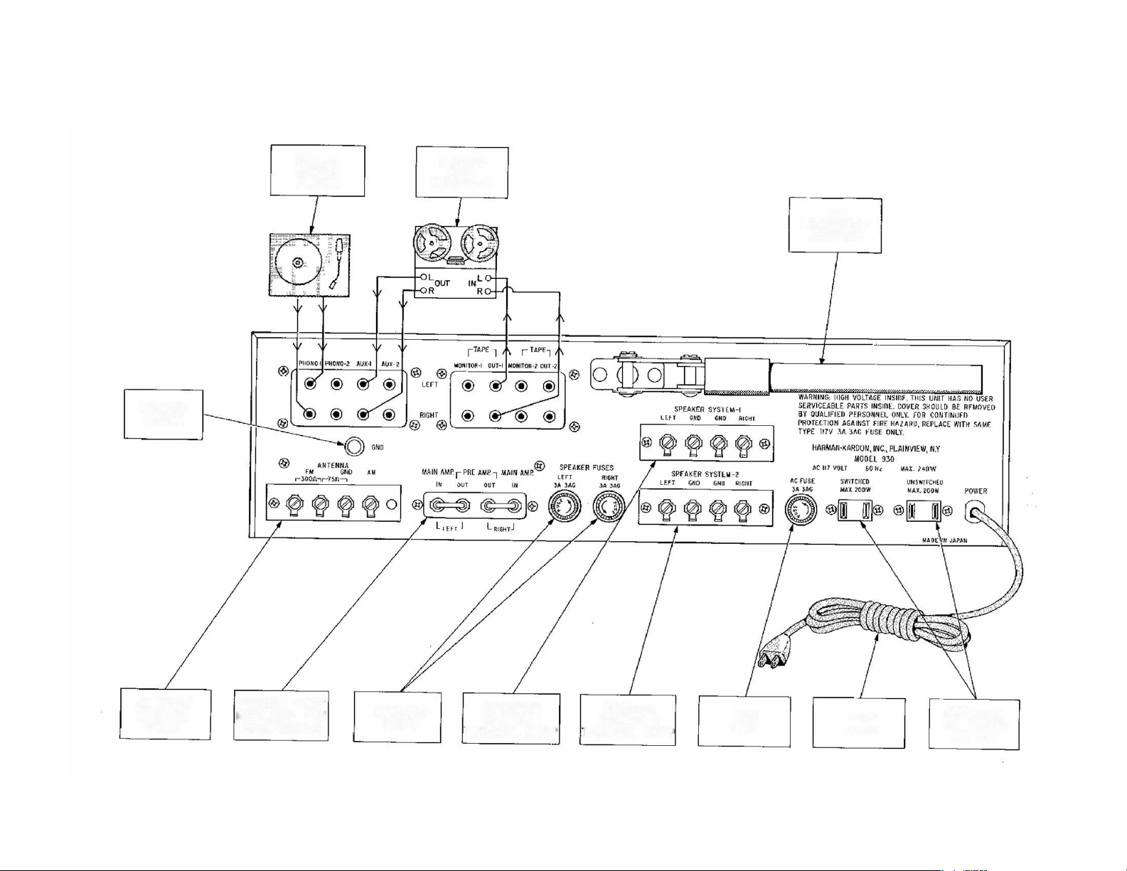
MODEL 930 REAR PANEL DIAGRAM
GROUND
SCREW
STEREO
RECORD
PLAYER
STEREO
TAPE
RECORDER
AM
LOOPSTICK
ANTENNA
ANTENNA
TERMINAL
STRIP
PREAMP "OUT"
MAIN AMP "IN"
RECEPTACLES
SPEAKER
FUSES
SPEAKER
SYSTEM I
LERMINAL STRIP
SPEAKER
SYSTEM 2
FERMINAL STRIP
s
UNE
FUSE
UNE
CORD
AUXILIARY
AC POWER
OUTLET
Page 10
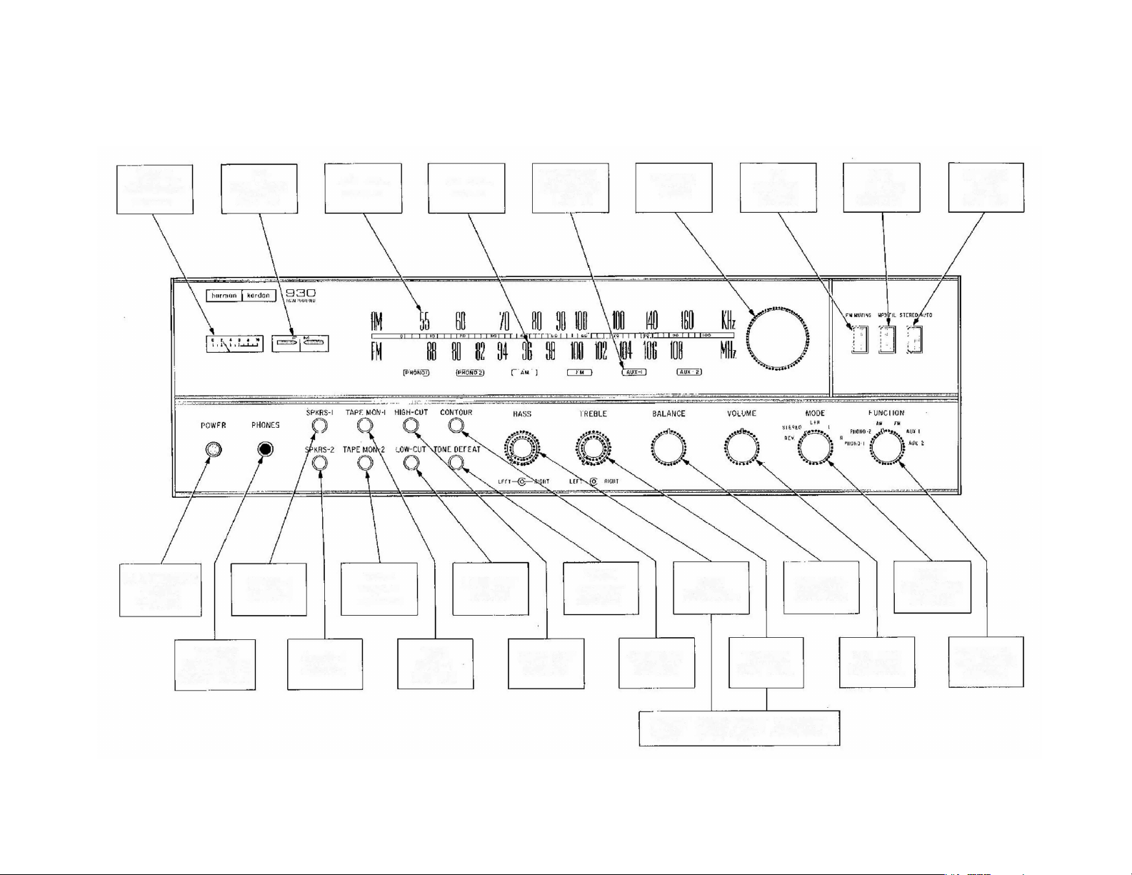
MODEL 930 FRONT PANEL DIAGRAM
SIGNAL
STRENGTH
METER
ILLUMINATED
POWER
SWITCH
FM
BALANCE
METER
SPKR-I
SWITCH
AM DIAL
SCALE
TAPE
MON-2
SWITCH
FM DIAL
SCALE
LOW-CUT
SWITCH
FUNCTION
INDICATOR
LIGHTS
TONE
DEFEAT
SWITCH
TUNING
KNOB
BASS
CONTROL
FM
MUTING
SWITCH
BALANCE
CONTROL
MPX
FILTER
SWITCH
STEREO
AUTO
SWITCH
MODE
SELECTOR
SWITCH
STEREO
HEADPHONE
RECEPTACLE
SPKR-2
SWITCH
TAPE
MON-1
SWITCH
HIGH-CUT
SWITCH
CONTOUR
SWITCH
FRONT KNOB*RIGHT CHANNEL
TREBLE
CONTROL
REAR KNOB»LEFT CHANNEL
VOLUME
CONTROL
FUNCTION
SELECTOR
SWITCH
Page 11

OPERATING PROCEDURE
Every control on this receiver serves ci specific useful function and is
important for the proper operation of your stereo system.
We recommend that you read the following section carefully so you may
take full advantage of the performance capabilities of your receiver.
VOLUME CONTROL
The VOLUME control adjusts the signal level of any program material con
nected to your stereo receiver. It is a two section control which simultaneously
adjusts both channels, and its close tracking specifications insure that the relative
volume level of each channel will be identical.
BALANCE CONTROL
The nature of stereo reproduction is such that it requires two identical
channels to attain the highest degree of faithfulness and spatial distribution.
Any variation in the efficiency of one channel as compared to the other will
disturb this relationship. Since there may be slight differences between the two
speakers, the tape heads, etc., your receiver includes a control to balance one
channel against the other. Sufficient range is covered by this control to permit
rebalancing of the overall system even in cases where major unbalance exists.
This control may be set anywhere within its range to attain system balance. It
does not necessarily have to be set in the exact vertical position.
When the BALANCE control is properly set, the apparent sound source will
lie in a broad area between the two speakers. When the BALANCE control is
rotated to the right the sound will move to the right and when the control is
rotated to the left, the sound will move to the left.
BASS AND TREBLE CONTROLS
The BASS and TREBLE controls on your receiver provide the full range
of tonal adjustment necessary for stereo high fidelity listening. The tone control
range is considerable and can adequately adjust the low and high frequencies
in accordance with your listening preference, speaker characteristics and room
acoustics.
You may adjust both the BASS and TREBLE for each channel simultaneously
or individually. The outer knob adjusts the LEFT channel and the inner knob
adjust the RIGHT channel. In order to adjust both channels turn either knob. In
order to adjust one channel only simply hold one knob while adjusting the other.
MODE SWITCH
The MODE switch selects between stereophonic and monophonic operation
depending upon the program source. The switch has five positions as follows:
1) REV......................... To reverse left and right channels for your listening
preference
2) STEREO ............... Normal stereo operation
3) L & R
4) L
51 R
......................
..................
.......................... Right channel signal to L & R channel
Combined left plus right channels
..........
Left channel signal to L & R channel
FUNCTION SWITCH
The FUNCTION switch has six positions and is used to select the desired
type of program source.
1 ) PHONO 1 (with RIAA equalization)
2) PHONO 2 (with RIAA equalization)
3) AM
4) FM
5) AUX 1
6) AUX 2
There are eleven remaining switches on the front panel of your receiver.
The switches used are all of the PUSH/PUSH type; that is push in to activate
the circuit and push again to release or de-activate the circuit. In describing
these switches we will consider the “IN” position to be “ON” and the
“OUT” position to be “OFF”.
POWER SWITCH
The POWER switch performs the function as its name denotes. It supplies
power to the receiver and to the switched AC convenience outlet. When the
switch is ON, function indicator lights will be illuminated.
If the function switch is in either the AM or FM position, the dial scale and
tuning meters will also be illuminated.
Page 12

SPEAKER SYSTEM SELECTOR SWITCHES
Your receiver has been provided with two independent speaker selector
switches.
It your receiver is connected with one set of speakers (1 system) as de
scribed in previous paragraph on speaker connections, the SPKR-1 switch must
be in the "on” position. If you have 2 sets of speakers [2 systems) the SPKR-1
and SPKR-2 switches must both be in the “on” position for both systems to
operate.
Should you desire to listen to stereo headphones alone, the speakers (either
one or both systems) can be turned off at your discretion.
TAPE MONITOR SWITCHES 1 and 2
Your receiver is provided with two pairs of TAPE OUT receptacles to permit
recording of program material being reproduced by your stereo system.
If your tape recorder is of the professional type and has a third head for
"monitoring”, it is possible to compare the recording with the original while it
is being made. Simply push the appropriate TAPE MONITOR switch (depending
on which TAPE MON receptacles you are using} to the IN position to listen to
the recording after if has been mode and back to the OUT position to listen
to the program material you are recording.
If you have two professional recorders, each with a monitoring feature, you
may monitor each one individually. However, if both TAPE MONITOR switches are
IN, TAPE MONITOR 2 will fake preference to prevent mixing of both channels.
HIGH CUT FILTER SWITCH
The HIGH CUT FILTER has been designed to reduce the high frequency
response of your receiver. This will reduce annoying record scratch, tape hiss,
FM background noise, etc.
LOW CUT FILTER SWITCH
At times, record changes, turntables and even some FM stations produce
an objectionable low frequency signal that is strong enough to be introduced into
the playback system. This is known as rumble and can be cancelled out by the
special low frequency cut off filter network included in this receiver. Whenever
rumble is present throw the LOW CUT switch "IN”.
TONE DEFEAT SWITCH
This switch permits you to remove the tone controls from the circuit to pro
vide an absolutely linear response. You may use this switch for instant comparison
of program material with either an equalized or flat response.
CONTOUR SWITCH
One of the limitations of human hearing is its tendency to lose sensitivity
to the very low pitched sounds as the program sound level is reduced. It is this
characteristic (known as the Fletcher-Munson effect) which causes one fa play
music programs at high listening levels in order to experience the full rich tone
available from fine modern recordings.
The Harman-Kardon CONTOUR switch compensates for this effect; thereby
eliminating high listening levels as a requisite for full enjoyment of reproduced
music. For warm, full-bodied reproduction at low listening, levels, throw the
CONTOUR switch to the IN position. At high levels, the CONTOUR switch has
no effect.
FM MUTING SWITCH
The purpose of the muting circuit is to reduce audible noise when tuning
from station to station. Since very weak signals may be muted at the same time,
the front panel FM MUTING switch may be used to defeat the muting circuit on
weak signals.
To reduce interstation noise, throw the MUTING switch "ON''. To defeat
the circuit, throw the switch "OFF".
MPX FILTER SWITCH
As FM multiplex reception requires greater signal strength at the antenna
terminals than monophonic reception, transmissions from weak or distant stations
will contain more noise than a monophonic signal of the same strength. This
switch will eliminate noise accompanying these weak multiplex signals.
STEREO AUTO SWITCH
Under normal use for all FM broadcasts the function selector switch should
be placed in the FM position and the stereo auto switch to the IN position.
Your receiver is equipped with a stereo sensing circuit which will auto
matically determine whether your unit is receiving monophonic or stereophonic
broadcasts, and then automatically adjust the mode of operation.
If the station is transmitting stereo, your receiver will automatically switch
on the multiplex section and you will hear the broadcast in full stereo. Should
the station conclude broadcasting in stereo, your receiver will automatically
switch back to monophonic reception.
Should you receive a weak stereo signal whose quality has been degraded
by noise or poor signal conditions, and you wish to listen to this stereo broadcast
monophonically, place the stereo auto switch in the OUT position.
Page 13

STEREO INDICATOR
A stereo indicator is located directly behind the dial glass and operates
in conjunction with the FM position of the Function switch and the Stereo Auto
“IN” position. The indicator visually shows the reproducton of FM stereo through
your receiver.
To tune for FM stereo proceed as follows:
1. Place the function selector switch in the FM position and the Stereo Auto
switch IN.
2. Tune to the station of your choice using your tuning meter for precise and
accurate tuning. Your stereo indicator will now show if you are tuned to a
stereo program. If the indicator is off, the program you are listening to
is being broadcast monophonically.
TUNING METERS
Your Receiver incorporates two D'Arsonvaf movement tuning meters for
precise and accurate tuning.
The FM balance meter is designed to operate on a null or “zero” center
principle. Therefore, the meter pointer should always be at the dead center
position of your meter dial for optimum listening performance. To accomplish this,
rotate your tuning knob slowly, in one direction towards the station of your
choice. As you tune through the station you will notice the pointer swinging from
the left or right past the zero center. THE CORRECT POINT for minimum distortion
and optimum FM reception is when the pointer is resting at the “zero” center
position.
The signal strength meter shows the level of the incoming signal. When
used in the FM position you should operate in conjunction with the FM balance
meter and tune for maximum indication on the signal strength meter as well
as a “zero” null on the balance meter.
When used in the AM position you simply tune for maximum indication.
FUNCTION INDICATOR LIGHTS
The function indicator lights are located behind the dial glass and visually
indicate the position of the function switch.
DIAL SCALE
The dial scale on your receiver is marked with three scales, namely, an
FM frequency scale {88-108 me), a logging scale {0-100), and an AM frequency
scale.
Since most FM stations operate at frequencies which are not whole num
bers (such as 96MC as compared to 96.3 MC), Ideally, each megacycle division
on the frequency scale should be divided into 10 parts to enable the user to
pinpoint the location of the station. This would require a dial scale which would
be longer than the front panel.
The logging scale which is divided into 100 equal parts provides a means
of finding your favorite station, once you have noted its position on the logging
scale. For example, in New York City, WQXR operates at 96.3 MC. After
locating this station through the use of the frequency scale (between 96 and 98
MC), you find that the pointer may fall on 42 on the logging scale. Make a
note of this setting. For future tuning to WQXR simply set the pointer to 42 on
the logging scale.
EQUALIZATION
In order to achieve good reproduction of the wide range of frequencies
in music and to make necessary adjustment for the limitations of the recording
technique, record manufacturers have found it necessary to modify the actual
frequency response of the music while it is being recorded. Thus, to avoid
overcutting and consequent distortion, a measured and deliberate reduction is
effected in low frequency response by selecting a “turnover frequency” and
recording attenuated response below that point. To assure optimum signal to
noise at the high frequency end when the record is played at home, the highs
are deliberately exaggerated during the recording process. A measured and
deliberate boost is affected above a certain frequency. This combination of
deliberate exaggeration at the low and high ends of the frequency spectrum
can be expressed in a recording curve. When the record is played a mirror
image of that curve should be available so that the ideal “flat” response may be
achieved.
The PHONO positions of the function switch automatically introduces the
proper equalization.
STEREO HEADPHONE RECEPTACLE
The stereo headphone receptacle located on the front panel will accept
any stereo headphone with any impedance rating. The headphone receptacle
is “on” at all times.
HUM AND NOISE
In any high fidelity installation, hum may be caused by the interconnection
of a record player, tuner and amplifier, as a result of the cables and different
grounds. If hum is experienced with your receiver, disconnect everything but
the speakers from the receiver. If hum persists, reverse the AC line cord. Plug
in the record player and if hum appears, reverse the record player power plug
and connect a single lead from the record player chassis to the ground post
on the rear of the receiver chassis. Connect your other devices in this manner.
CAUTION: Hum may also be induced by defective connecting cables or by
running these cables too close to a strong AC field.
SERVICE
If this instrument should not perform properly during the first two (2) years
after date of purchase, contact the factory for instructions. The factory has many
authorized warranty service stations in the United States. To aid us in selecting
a service station convenient to you, it would be helpful If you would indicate
which major city is closest to your home. Please write our Customer Service
Department, Harman-Kardon, Incorporated, Plainview, New York 1 1803. Be
sure to include the model and serial number of the unit. A brief description of
your other components is often of help in answering your questions. DO NOT
return this instrument to Harman-Kardon without first receiving authorization,
 Loading...