

Page 1
Engineering Data
AC Servo Actuators CHA
More information on our servo products
can be found HERE!
Contact us today!
Page 2

Contents
1. General .................................................................................................................................................. 5
1.1 Description of Safety Alert Symbols ....................................................................................................................................6
1.2 Disclaimer and Copyright ......................................................................................................................................................6
2. Safety and Installation Instructions .....................................................................................................7
2.1 Hazards ..................................................................................................................................................................................7
2.2 Intended Purpose ................................................................................................................................................................. 8
2.3 Non Intended Purpose ......................................................................................................................................................... 8
2.4 Use in Special Application Areas ..........................................................................................................................................9
2.5 Declaration of Conformity .....................................................................................................................................................9
2.5.1 Gears ...........................................................................................................................................................................9
2.5.2 Servo Actuators and Motors .....................................................................................................................................9
3. Technical Description ...........................................................................................................................10
4. Ordering Code .......................................................................................................................................11
5. Combinations .......................................................................................................................................12
6. Technical Data ......................................................................................................................................13
6.2 Actuator Data CHA-14A-E ................................................................................................................................................... 14
6.2.1 Technical Data .......................................................................................................................................................... 14
6.2.2 Moment of Inertia ................................................................................................................................................... 15
6.2.3 Technical Data Brake ................................................................................................................................................ 15
6.2.4 Performance Characteristics ................................................................................................................................... 16
6.3 Actuator Data CHA-14A-H/N ...............................................................................................................................................17
6.3.1 Technical Data ...........................................................................................................................................................17
6.3.2 Moment of Inertia ................................................................................................................................................... 18
6.3.3 Technical Data Brake ................................................................................................................................................18
6.3.4 Performance Characteristics ................................................................................................................................... 19
6.4 Actuator Data CHA-17A-E .................................................................................................................................................. 20
6.4.1 Technical Data ......................................................................................................................................................... 20
6.4.2 Moment of Inertia ................................................................................................................................................... 21
6.4.3 Technical Data Brake ................................................................................................................................................ 21
6.4.4 Performance Characteristics ...................................................................................................................................22
6.5 Actuator Data CHA-17A-H/N ...............................................................................................................................................23
6.5.1 Technical Data ..........................................................................................................................................................23
6.5.2 Moment of Inertia ...................................................................................................................................................24
6.5.3 Technical Data Brake ................................................................................................................................................24
6.5.4 Performance Characteristics ...................................................................................................................................25
6.6 Actuator Data CHA-20A-C1024 ...........................................................................................................................................26
6.6.1 Technical Data ..........................................................................................................................................................26
6.6.2 Moment of Inertia ...................................................................................................................................................26
6.6.3 Technical Data Brake ................................................................................................................................................26
6.6.4 Performance Characteristics ...................................................................................................................................27
6.7 Actuator Data CHA-25A-C1024 .......................................................................................................................................... 28
6.7.1 Technical Data ......................................................................................................................................................... 28
6.7.2 Moment of Inertia .................................................................................................................................................. 28
6.7.3 Technical Data Brake ............................................................................................................................................... 28
6.7.4 Performance Characteristics ...................................................................................................................................29
6.8 Actuator Data CHA-32A-C1024 .......................................................................................................................................... 30
6.8.1 Technical Data ......................................................................................................................................................... 30
6.8.2 Moment of Inertia .................................................................................................................................................. 30
6.8.3 Technical Data Brake ............................................................................................................................................... 30
6.8.4 Performance Characteristics ................................................................................................................................... 31
2 1018854 8/2018 V03
Page 3

6.9 Actuator Data CHA-40A-C1024 ..........................................................................................................................................32
6.9.1 Technical Data ..........................................................................................................................................................32
6.9.2 Moment of Inertia ...................................................................................................................................................32
6.9.3 Technical Data Brake ................................................................................................................................................32
6.9.4 Performance Characteristics ...................................................................................................................................33
6.10 Actuator Data CHA-50A-C1024 .......................................................................................................................................... 34
6.10.1 Technical Data ......................................................................................................................................................... 34
6.10.2 Moment of Inertia .................................................................................................................................................. 34
6.10.3 Technical Data Brake ............................................................................................................................................... 34
6.10.4 Performance Characteristics ...................................................................................................................................35
6.11 Actuator Data CHA-58A-C1024 ...........................................................................................................................................36
6.11.1 Technical Data ..........................................................................................................................................................36
6.11.2 Moment of Inertia ...................................................................................................................................................36
6.11.3 Technical Data Brake ................................................................................................................................................36
6.11.4 Performance Characteristics ...................................................................................................................................37
6.12 Actuator Data CHA-20A-M512P ......................................................................................................................................... 38
6.12.1 Technical Data ......................................................................................................................................................... 38
6.12.2 Moment of Inertia .................................................................................................................................................. 38
6.12.3 Technical Data Brake ............................................................................................................................................... 38
6.12.4 Performance Characteristics ...................................................................................................................................39
6.13 Actuator Data CHA-25A-M512P ......................................................................................................................................... 40
6.13.1 Technical Data ......................................................................................................................................................... 40
6.13.2 Moment of Inertia .................................................................................................................................................. 40
6.13.3 Technical Data Brake ...............................................................................................................................................40
6.13.4 Performance Characteristics ................................................................................................................................... 41
6.14 Actuator Data CHA-32A-M512P ..........................................................................................................................................42
6.14.1 Technical Data ..........................................................................................................................................................42
6.14.2 Moment of Inertia ...................................................................................................................................................42
6.14.3 Technical Data Brake ................................................................................................................................................42
6.14.4 Performance Characteristics .................................................................................................................................. 43
6.15 Actuator Data CHA-40A-M512P ........................................................................................................................................ 44
6.15.1 Technical Data ......................................................................................................................................................... 44
6.15.2 Moment of Inertia .................................................................................................................................................. 44
6.15.3 Technical Data Brake ............................................................................................................................................... 44
6.15.4 Performance Characteristics .................................................................................................................................. 45
6.16 Actuator Data CHA-50A-M512P ......................................................................................................................................... 46
6.16.1 Technical Data ......................................................................................................................................................... 46
6.16.2 Moment of Inertia .................................................................................................................................................. 46
6.16.3 Technical Data Brake ............................................................................................................................................... 46
6.16.4 Performance Characteristics ...................................................................................................................................47
6.17 Actuator Data CHA-58A-M512P .........................................................................................................................................48
6.17.1 Technical Data ......................................................................................................................................................... 48
6.17.2 Moment of Inertia .................................................................................................................................................. 48
6.17.3 Technical Data Brake ............................................................................................................................................... 48
6.17.4 Performance Characteristics .................................................................................................................................. 49
6.18 Dimensions ......................................................................................................................................................................... 50
6.19 Accuracy .............................................................................................................................................................................. 54
6.20 Torsional Stiness.............................................................................................................................................................. 54
6.21 Output Bearing ....................................................................................................................................................................55
6.21.1 Technical Data ..........................................................................................................................................................55
6.21.2 Tolerances ................................................................................................................................................................55
6.22 Motor Feedback Systems ...................................................................................................................................................56
6.22.1 C1024 ........................................................................................................................................................................ 57
6.22.2 M512P ...................................................................................................................................................................... 58
6.22.3 RES .......................................................................................................................................................................... 58
6.22.4 M128S .......................................................................................................................................................................59
6.22.5 D2048 ....................................................................................................................................................................... 61
31018854 8/2018 V03
Page 4

6.23 Temperature Sensors ..........................................................................................................................................................62
6.24 Electrical Connections .........................................................................................................................................................63
6.24.1 CHA-xx-H-C1024 / H-M512P / H-M128S .................................................................................................................63
6.24.2 CHA-xx-H-RES .........................................................................................................................................................65
6.24.3 CHA-xx-N-RES / N-M128S / N-D2048 .................................................................................................................. 66
6.24.4 CHA-xx-E-RES / E-M128S / E-D2048 .....................................................................................................................67
6.25 Options ................................................................................................................................................................................ 68
7. Actuator Selection Procedure ............................................................................................................ 69
7.1. Selection Procedure and Calculation Example ...................................................................................................................69
7.2 Calculation of the Torsion Angle ......................................................................................................................................... 73
7.3 Output Bearing ....................................................................................................................................................................74
7.3.1 Lifetime Calculation for Continuous Operation .....................................................................................................74
7.3.2 Lifetime Calculation for Oscillating Motion ...........................................................................................................74
7.3.3 Permissible Static Tilting Moment ......................................................................................................................... 76
7.3.4 Angle of Inclination .................................................................................................................................................76
8. Design Notes .......................................................................................................................................77
8.1 Notes on the Fit Selection .................................................................................................................................................. 77
9. Installation and Operation ................................................................................................................. 78
9.1 Transport and Storage .........................................................................................................................................................78
9.2 Installation ...........................................................................................................................................................................78
9.3 Mechanical Installation ....................................................................................................................................................... 79
9.4 Electrical Installation .......................................................................................................................................................... 80
9.5 Commissioning .................................................................................................................................................................... 81
9.6 Overload Protection ............................................................................................................................................................. 81
9.7 Protection against Corrosion and Penetration of Liquids and Debris ............................................................................. 82
9.8 Shutdown and Maintenance .............................................................................................................................................. 82
10. Decommissioning and Disposal ......................................................................................................... 84
11. Glossary ............................................................................................................................................... 85
11.1 Technical Data .................................................................................................................................................................... 85
11.2 Labelling, Guidelines and Regulations ...............................................................................................................................92
4 1018854 8/2018 V03
Page 5

1. General
About this documentation
This document contains safety instructions, technical data and operation rules for servo actuators and servo motors of
Harmonic Drive AG.
The documentation is aimed at planners, project engineers, commissioning engineers and machine manufacturers, oering
support during selection and calculation of the servo actuators, servo motors and accessories.
Rules for storage
Please keep this document for the entire life of the product, up to its disposal. Please hand over the documentation when
re-selling the product.
Additional documentation
For the configuration of drive systems using the products of Harmonic Drive AG, you may require additional documents.
Documentation is provided for all products oered by Harmonic Drive AG and can be found in pdf format on the website.
www.harmonicdrive.de
Third-party systems
Documentation for parts supplied by third party suppliers, associated with Harmonic Drive® components, is not included in
our standard documentation and should be requested directly from the manufacturers.
Before commissioning servo actuators and servo motors from Harmonic Drive AG with servo drives, we advise you to obtain
the relevant documents for each device.
Your feedback
Your experiences are important to us. Please send suggestions and comments about the products and documentation to:
Harmonic Drive AG
Marketing and Communications
Hoenbergstraße 14
65555 Limburg / Lahn
Germany
E-Mail: info@harmonicdrive.de
51018854 8/2018 V03
Page 6
1.1 Description of Safety Alert Symbols
Symbol Meaning
Indicates an imminent hazardous situation. If this is not avoided, death or
DANGER
WARNING
ATTENTION
ADVICE
serious injury could occur.
Indicates a possible hazard. Care should be taken or death or serious injury may
result.
Indicates a possible hazard. Care should be taken or slight or minor injury
may result.
Describes a possibly harmful situation. Care should be taken to avoid damage
to the system and surroundings.
INFORMATION
This is not a safety symbol. This symbol indicates important information.
Warning of a general hazard. The type of hazard is determined by the
specific warning text.
Warning of dangerous electrical voltage and its eects.
Beware of hot surfaces.
Beware of suspended loads.
Precautions when handling electrostatic sensitive components.
Beware of electromagnetic environmental compatibility.
1.2 Disclaimer and Copyright
The contents, images and graphics contained in this document are predected by copyright. In addition to the copyright, logos,
fonts, company and product names can also be predected by brand law or trademark law. The use of text, extracts or graphics
requires the permission of the publisher or rights holder.
We have checked the contents of this document. Since errors cannot be ruled out entirely, we do not accept liability for mistakes which may have occurred. Notification of any mistake or suggestions for improvements will be gratefully received and any
necessary correction will be included in subsequent editions.
6 1018854 8/2018 V03
Page 7

2. Safety and Installation Instructions
Please take note of the information and instructions in this document. Specially designed models may dier in technical
detail. If in doubt, we recommend to contact the manufacturer, giving the type designation and serial number for
clarification.
2.1 Hazards
DANGER
Electric servo actuators and motors have dangerous live and rotating parts. All work during connection, operation, repair and
disposal must be carried out by qualified personnel as described in the standards EN 50110-1 and IEC 60364! Before starting
any work, and especially before opening covers, the actuator must be properly isolated. In addition to the main circuits, the
user also has to pay attention to any auxilliary circuits.
Observing the five safety rules:
• Disconnect mains
• Prevent reconnection
• Test for absence of harmful voltages
• Ground and short circuit
• Cover or close o nearby live parts
The measures taken above must only be withdrawn when the work has been completed and the device is fully assembled.
Improper handling can cause damage to persons and property. The respective national, local and factory specific regulations
must be adhered to.
ATTENTION
The surface temperature of gears, motors and actuators can exceed 55 degrees Celsius. The hot surfaces should not be touched.
ADVICE
Cables must not come into direct contact with hot surfaces.
DANGER
Electric, magnetic and electromagnetic fields are dangerous, in particular for persons with pacemakers, implants or similiar.
Vulnerable individuals must not be in the close proximity of the products themselves.
DANGER
Built-in holding brakes are not functional safe by themselves. Particularly with unsupported vertical axes, functional safety
can only be achieved with additional, external mechanical brakes.
71018854 8/2018 V03
Page 8

DANGER
Danger of injury due to improper handling of batteries.
Observing of the battery safety rules:
• do not insert batteries in reverse. Observe the + and - marks on the battery and on the electrical device
• do not short circuit
• do not recharge
• do not open or deform
• do not expose to fire, water or high temperature
• do not leave discharged batteries in the electrical device
• keep batteries out of reach of children. In case of ingestion of a battery, seek medical assistance promptly.
WARNING
The successful and safe operation of gears, servo actuators and motors requires proper transport, storage and assembly as
well as correct operation and maintenance.
ATTENTION
Use suitable lifting equipment to move and lift gears, servo actuators and motors with a weight > 20 kg.
INFORMATION
Special versions of products may dier in the specification from the standard. Further applicable data from data sheets,
catalogues and oers of the special version have to be considered.
2.2 Intended Purpose
Harmonic Drive® Products are intended for industrial or commercial applications.
Typical areas of application are robotics and handling, machine tools, packaging and food machines and similar machines.
The products may only be operated within the operating ranges and environmental conditions shown in the documentation
(altitude, degree of predection, temperature range, etc).
Before commissioning of plants and machinery including Harmonic Drive® Products, the compliance with the Machinery
Directive must be established.
2.3 Non Intended Purpose
The use of products outside the areas of application mentioned above or beyond the operating areas or environmental
conditions described in the documentation is considered as non-intended purpose.
8 1018854 8/2018 V03
Page 9

2.4 Use in Special Application Areas
The use of the products in one of the following application areas requires a risk assessment and approval by
Harmonic Drive AG.
• Aerospace
• Areas at risk of explosion
• Machines specially constructed or used for a nuclear purpose whose breakdown might lead to the emission of radio-activity
• Vacuum
• Household devices
• Medical equipment
• Devices which interact directly with the human body
• Machines or equipment for transporting or lifting people
• Special devices for use in annual markets or leisure parks
2.5 Declaration of Conformity
2.5.1 Gears
Harmonic Drive® Gears are components for installation in machines as defined by the Machinery Directive.
Commissioning is prohibited until the end product conforms to the provisions of this directive.
Essential health and safety requirements were considered in the design and manufacture of these gear component sets.
This simplifies the implementation of the Machinery Directive by the end user for the machinery or the partly completed
machinery. Commissioning of the machine or partly completed machine is prohibited until the end product conforms to the
Machinery Directive.
2.5.2 Servo Actuators and Motors
The Harmonic Drive® Servo Actuators and Motors described in the engineering data comply with the Low Voltage Directive.
In accordance with the Machinery Directive, Harmonic Drive® Servo Actuators and Motors are electrical equipment
for the use within certain voltage limits as covered by the Low Voltage Directive and thus excluded from the scope of the
Machinery Directive. Commissioning is prohibited until the final product conforms to the Machinery Directive.
According to the EMC directive Harmonic Drive® Servo Actuators and Motors are inherently benign equipment, unable to
generate electromagnetic disturbance or to be aected by such disturbance.
The conformity to the EU directives of equipment, plant and machinery in which Harmonic Drive® Servo Actuators and Motors
are installed must be provided by the user before taking the device into operation.
Equipment, plant and machinery with inverter driven motors must satisfy the protection requirements of the EMC directive.
It is the responsibility of the user to ensure that the installation is carried out correctly.
91018854 8/2018 V03
Page 10

3. Technical Description
Largest hollow shaft with precision output bearing
CHA Series Hollow Shaft Servo Actuators combine a synchronous servo motor, Unit from the CPU-H Series, feedback sensor
and a high capacity precision output bearing. Available in eight sizes with gear ratios between 30 and 160:1, the actuators can
provide maximum torques from 8 to 1840 Nm. The output bearing with high tilting capacity often allows direct attachment of
heavy payloads without the need for further support, thereby providing simple and space saving design installations.
To adapt to your specific application, the CHA Series oers many possible combinations when selecting the motor winding,
Motor feedback system, brake, various sensors and cable as well as connector options.
The integrated hollow shaft can be used to feed through supply lines or services for additional axes, enabling space saving
designs with minimal installation dimensions required. With a reinforced output bearing oering maximum tilting rigidity,
the actuators can easily absorb and accurately guide heavy payloads. The accurate positioning of the actuator ensures stable
machine characteristics, increased operating reliability and consistent quality. With high predection ratings and corrosion
resistance, the series is perfectly suited for use in harsh and demanding environmental conditions.
By combining the CHA Actuators with the specially adapted YukonDrive® Servo Controllers, it is possible to provide a single
source supply for a pre-configured drive system tailored to suit your application. Alternatively, the flexible configuration of
the actuator ensures compatibility with almost any servo controller on the market.
10 1018854 8/2018 V03
Page 11
4. Ordering Code
Table 11.1
Series
CHA
Ordering code
CHA 20A 100 H C1024 B EC K SP
Table 11.2
Version
Size
Version
14A
17A
20A
25A
32A
40A
50A
58A
- -- - - -- -
Motor winding and connector configuration
Size
14A
17A
14A
17A
20A
25A
32A
40A
50A
58A
30
30
30
30
30
Ordering code
50
50
50
50
50
50
50
50
E
H, N
Ratio
80
80
80
80
80
80
80
80
100
100
120
100
120
100
120
100
120
100
120
100
120
100
120
Maximum DC bus
680 VDC
Motor winding and
connector configuration
160
160
160
160
160
160
voltage
48 VDC
Motor feed-
back system
E
H
N
Table 11.3
Ordering
code
H C1024
H M512P x
H M128S x
H RES 12 pin (M23) x
N M128S
N RES x
N D2048 x
E RES
E D2048 x
E M128S x
C1024
M512P
RES
D2048
M128S
Motor
feedback
Brake Option 1 Option 2
B Sensor
connector configuration
Motor
6 pin
(M23)
8 pin
(M17)
8 pin
(M17)
Motor
feedback
system
17 pin (M23)
17 pin (M17)
17 pin (M17)
connec-
Cable/
tor
Cable
outlet
Special
design
According
to customer
requirements
connec-
tor
x
x
x
Table 11.4
Motor feedback system
Ordering code Typ Protocol
C1024 Incremental –
M512P Multi-turn absolute EnDat®
RES Resolver
D2048 Incremental
M128S Multi-turn absolute SSI
Table 11.5
Option 1
Ordering code Description
EC
Table 11.6
Ordering code Description
K Cable outlet axial
R connector axial (only M512P)
S connector radial (only M512P)
- Standard (cable outlet radial)
Clarification of the technical data can be found in the Glossary
Single turn absolute EnDat®
Encoder system at the gear output
Option 2
111018854 8/2018 V03
Page 12

5. Combinations
Table 12.1
Ratio
Size
Version
30
50
80
100
14A 17A 20A 25A 32A 40A 50A 58A
120 160 - -
Motor winding and connector configuration
E
H
L - N
C1024 - -
M512P - -
Motor feedback system
RES
D2048
M128S
Brake B
Option 1 (Sensor) EC - -
1)
Option 2 (Cable/ connector)
K
R - S - -
available on request – not available 1) Only for resolver and with increased length
- - -
- - - - - -
- - - - - -
- - - - - -
- - - - - -
1)
Only in conjunction with M512P
Gear Component Set
• Zero backlash
• Hollow shaft
• Transmission accuracy better than 1 arcmin
• Repeatability better than ±6 arcsec
Output bearing
• High load capacity
• Tilt resistant
• Excellent running characteristics
Motor feedback system
• Incremental encoder
• Single- or multi-turn absolute encoder
• EnDat® multi-turn encoder
• Resolver
AC Hollow shaft motor
• Sine commutated hollow shaft AC motor
• Multiple motor winding options
• Winding temperature monitoring with
temperature sensor
• Maintenance free
12 1018854 8/2018 V03
Page 13

6. Technical Data
CHA-xxA-E
Table 13.1
Insulation class (EN 60034-1) F
Insulation resistance (500 VDC) MΩ 100
Insulation voltage (10 s) V
Lubrication Flexolub®-A1
Degree of predection (EN 60034-5) IP65
Ambient operating temperature °C 0 … 40
Ambient storage temperature °C -20 … 60
Relative humidity (without condensation) % 20 … 80
Vibration resistance (DIN IEC 68 Part 2-6, 10 … 500 Hz) g 5
Shock resistance (DIN IEC 68 Part 2-27, 18 ms) g 30
Corrosion protection (DIN IEC 68 Part 2-11 salt spray test) h 4
Temperature sensors 1 x KTY 84-130 / 1 x PTC
rms
600
CHA-xxA-H/N
Table 13.2
Insulation class (EN 60034-1) F
Insulation resistance (500 VDC) MΩ 100
Insulation voltage (10 s) V
Lubrication Flexolub®-A1
Degree of predection (EN 60034-5) IP65
Ambient operating temperature °C 0 … 40
Ambient storage temperature °C -20 … 60
Altitude (a. s. l.) m < 1000
Relative humidity (without condensation) % 20 … 80
Vibration resistance (DIN IEC 68 Part 2-6, 10 … 500 Hz) g 5
Shock resistance (DIN IEC 68 Part 2-27, 18 ms) g 30
Corrosion protection (DIN IEC 68 Part 2-11 salt spray test) h 4
Temperature sensors 1 x KTY 84-130 / 1 x PTC
rms
2500
The continuous operating characteristics given in the following apply to an ambient temperature of 40 °C and an aluminium
cooling surface with the following dimensions:
Table 13.3
Series
CHA
Size
Version
14A [mm] 200 x 200 x 6
17A [mm] 300 x 300 x 15
20A [mm] 300 x 300 x 15
25A [mm] 350 x 350 x 18
32A [mm] 350 x 350 x 18
40A [mm] 400 x 400 x 20
50A [mm] 500 x 500 x 25
58A [mm] 600 x 600 x 30
Unit Dimensions
131018854 8/2018 V03
Page 14
6.2 Actuator Data CHA-14A-E
6.2.1 Technical Data
Table 14.1
Symbol
[Unit]
CHA-14A-E
Motor feedback system RES / D2048 / M128S
Ratio i [ ] 30 50 80 100
Maximum output torque T
Maximum output speed n
Maximum current I
Continuous stall torque T
Continuous stall current I
Maximum DC bus voltage U
Electrical time constant (20 °C) t
Mechanical time constant (20 °C) Version RES t
Mechanical time constant (20 °C) Version D2048 t
Mechanical time constant (20 °C) Version M128S t
No load current (+20 °C) I
No load current (-40 °C) I
No load running current constant (30 °C) K
No load running current constant (80 °C) K
Torque constant (at output) k
Torque constant (at motor) k
AC voltage constant (L-L, 20 °C, at motor) k
Motor terminal voltage (fundamental wave only) U
Demagnetisation current I
Maximum motor speed n
Rated motor speed n
Resistance (L-L, 20 °C) R
Inductance (L-L) L
[Nm] 9 18 23 28
max
[rpm] 283 170 106 85
max
[A
] 7.4 8.6 6.9 6.7
max
rms
[Nm] 6.8 6.9 11 11
0
[A
] 5.8 3.8 3.7 3.1
0
rms
[VDC] 48
DCmax
[ms] 0.8
e
[ms] 14.0
m
[ms] 9.0
m
[ms] 23.0
m
[A
] 1.0 0.9 0.8 0.8
NLS
rms
[A
] 3.1 3.7 4.5 5.1
NLS
rms
INL
INL
[V
EM
[·10-3 A
[·10-3 A
Tout
/rpm] 4.6 7.6 12.2 15.2
rms
/rpm] 1.6 2.7 4.3 5.4
rms
[Nm/A
[Nm/A
TM
rms
E
max
N
L- L
] 1.2 1.8 3.0 3.5
rms
] 0.04
rms
/1000 rpm] 3
[V
] 18 … 34
M
rms
[A
] -
rms
[rpm] 8500
[rpm] 3500
[Ω] 0.42
L- L
[mH] 0.35
Number of pole pairs p [ ] 5
Weight without brake m [kg]
Weight with brake m [kg]
Hollow shaft diameter d
[mm] 12
H
1.4 (D2048)
2.0 (RES / M128S)
1.7 (D2048)
2.3 (RES / M128S)
14 1018854 8/2018 V03
Page 15

6.2.2 Moment of Inertia
Table 15.1
Symbol
[Unit]
CHA-14A
Motor feedback system RES
Ratio i [ ] 30 50 80 100
Moment of Inertia output side
Moment of inertia without brake J
Moment of inertia with brake J
[kgm²] 0.031 0.087 0.222 0.347
out
[kgm²] 0.039 0.109 0.280 0.438
out
Moment of Inertia at motor
-4
Moment of inertia at motor without brake J [·10
Moment of inertia at motor with brake J [·10
kgm²] 0.347
-4
kgm²] 0.438
Motor feedback system D2048
Ratio i [ ] 30 50 80 100
Moment of Inertia output side
Moment of inertia without brake J
Moment of inertia with brake J
[kgm²] 0.020 0.056 0.142 0.223
out
[kgm²] 0.028 0.078 0.201 0.314
out
Moment of Inertia at motor
-4
Moment of inertia at motor without brake J [·10
Moment of inertia at motor with brake J [·10
kgm²] 0.223
-4
kgm²] 0.314
Motor feedback system M128S
Ratio i [ ] 30 50 80 100
Moment of Inertia output side
Moment of inertia without brake J
Moment of inertia with brake J
[kgm²] 0.052 0.145 0.371 0.580
out
[kgm²] 0.060 0.168 0.429 0.671
out
Moment of Inertia at motor
-4
Moment of inertia at motor without brake J [·10
Moment of inertia at motor with brake J [·10
kgm²] 0.580
-4
kgm²] 0.671
6.2.3 Technical Data Brake
Table 15.2
Symbol
[Unit]
Ratio i [ ] 30 50 80 100
Brake voltage U
Brake holding torque (at output) T
Brake current to open I
Brake current to hold I
[VDC] 24 ±10 %
Br
[Nm] 9 18 23 28
Br
[ADC] -
OBr
[ADC] 0.54
HBr
Number of brake cyles at n = 0 rpm -
Emergency brake cyles -
Opening time t
Closing time t
[ms] -
O
[ms] -
C
CHA-14A
151018854 8/2018 V03
Page 16
-1
CHA-14A-30-E
25
Drehzahl [min-1] / Speed [rpm]
CHA-14A-80-E
-1
CHA-14A-50-E
30
Drehzahl [min-1] / Speed [rpm]
CHA-14A-100-E
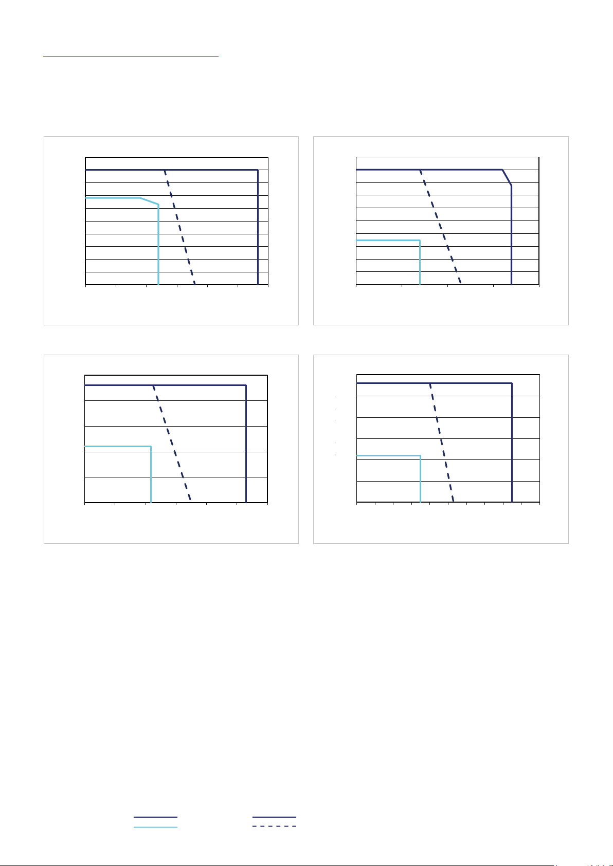
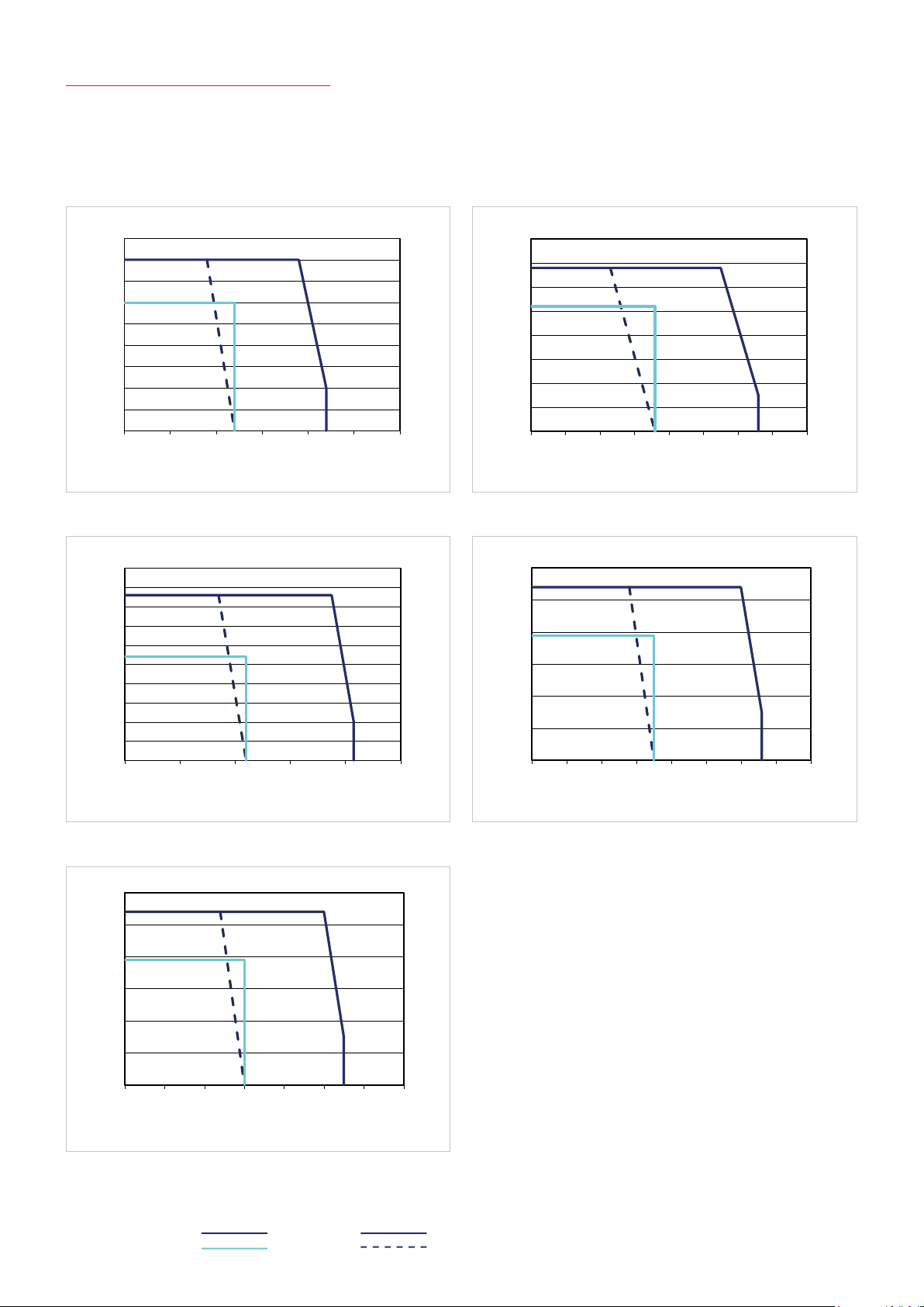
6.2.4 Performance Characteristics
The performance curves shown below are valid for the specified ambient operating temperature if the motor terminal
voltage is higher or equal to the values given in the ratings table.
Illustration 16.1 Illustration 16.2
10
9
8
7
6
5
4
Torque [Nm]
3
2
1
Drehmoment [Nm] / Torque [Nm]
0
0 50 100 150 200 250 300
Speed [rpm]
Illustration 16.3 Illustration 16.4
20
CHA-14A-30-E CHA-14A-50-E
20
18
16
14
12
10
8
Torque [Nm]
6
4
2
Drehmoment [Nm] / Torque [Nm]
0
0 50 100 150 200
CHA-14A-80-E CHA-14A-100-E
25
20
15
15
10
Torque [Nm]
5
Drehmoment [Nm] / Torque [Nm]
0
0 20 40 60 80 100 120
Speed [rpm]
Torque [Nm]
10
5
0
0 10 20 30 40 50 60 70 80 90 100
Speed [rpm]
Speed [rpm]
Legend
Intermittent duty L: U
Continuous duty H: UM = 18 VAC
16 1018854 8/2018 V03
= 34 VAC
M
Page 17
6.3 Actuator Data CHA-14A-H/N
6.3.1 Technical Data
Table 17.1
Symbol
[Unit]
CHA-14A-H/N
Motor feedback system RES / D2048 / M128S
Ratio i [ ] 30 50 80 100
Maximum output torque T
Maximum output speed n
Maximum current I
Continuous stall torque T
Continuous stall current I
Maximum DC bus voltage U
Electrical time constant (20 °C) t
Mechanical time constant (20 °C) Version RES t
Mechanical time constant (20 °C) Version D2048 t
Mechanical time constant (20 °C) Version M128S t
No load current I
No load running current constant (30 °C) K
No load running current constant (80 °C) K
Torque constant (at output) k
Torque constant (at motor) k
AC voltage constant (L-L, 20 °C, at motor) k
Motor terminal voltage (fundamental wave only) U
Demagnetisation current I
Maximum motor speed n
Rated motor speed n
Resistance (L-L, 20 °C) R
Inductance (L-L) L
[Nm] 9 18 23 28
max
[rpm] 283 170 106 85
max
[A
] 1.1 1.3 1.0 1.0
max
rms
[Nm] 6.8 6.9 11 11
0
[A
] 0.9 0.6 0.6 0.5
0
rms
[VDC] 680
DCmax
[ms] 1.9
e
[ms] 4.4
m
[ms] 3.0
m
[ms] 7.4
m
[A
] 0.1 3 0.12 0.10 0.10
NLS
rms
INL
INL
[V
EM
[·10-3 A
[·10-3 A
Tout
/rpm] 0.5 0.8 1 2
rms
/rpm] 0.2 0.3 0.5 0.6
rms
[Nm/A
[Nm/A
TM
rms
E
max
N
L- L
] 9.4 14.4 24.4 31.4
rms
] 0.30
rms
/1000 rpm] 22
[V
] 220 … 430
M
rms
[A
] -
rms
[rpm] 8500
[rpm] 3500
[Ω] 7.7
L- L
[mH] 15.0
Number of pole pairs p [ ] 5
Weight without brake m [kg]
Weight with brake m [kg]
Hollow shaft diameter d
[mm] 12
H
1.4 (D2048)
2.0 (RES / M128S)
1.7 (D2048)
2.3 (RES / M128S)
171018854 8/2018 V03
Page 18

6.3.2 Moment of Inertia
Table 18.1
Symbol
[Unit]
CHA-14A
Motor feedback system RES
Ratio i [ ] 30 50 80 100
Moment of Inertia output side
Moment of inertia without brake J
Moment of inertia with brake J
[kgm²] 0.031 0.087 0.222 0.347
out
[kgm²] 0.039 0.109 0.280 0.438
out
Moment of Inertia at motor
-4
Moment of inertia at motor without brake J [·10
Moment of inertia at motor with brake J [·10
kgm²] 0.347
-4
kgm²] 0.438
Motor feedback system D2048
Ratio i [ ] 30 50 80 100
Moment of Inertia output side
Moment of inertia without brake J
Moment of inertia with brake J
[kgm²] 0.020 0.056 0.142 0.223
out
[kgm²] 0.028 0.078 0.201 0.314
out
Moment of Inertia at motor
-4
Moment of inertia at motor without brake J [·10
Moment of inertia at motor with brake J [·10
kgm²] 0.223
-4
kgm²] 0.314
Motor feedback system M128S
Ratio i [ ] 30 50 80 100
Moment of Inertia output side
Moment of inertia without brake J
Moment of inertia with brake J
[kgm²] 0.052 0.145 0.371 0.580
out
[kgm²] 0.060 0.168 0.429 0.671
out
Moment of Inertia at motor
-4
Moment of inertia at motor without brake J [·10
Moment of inertia at motor with brake J [·10
kgm²] 0.580
-4
kgm²] 0.671
6.3.3 Technical Data Brake
Table 18.2
Symbol
[Unit]
Ratio i [ ] 30 50 80 100
Brake voltage U
Brake holding torque (at output) T
Brake current to open I
Brake current to hold I
[VDC] 24 ±10 %
Br
[Nm] 9 18 23 28
Br
[ADC] -
OBr
[ADC] 0.54
HBr
Number of brake cyles at n = 0 rpm -
Emergency brake cyles -
Opening time t
Closing time t
[ms] -
O
[ms] -
C
CHA-14A
18 1018854 8/2018 V03
Page 19
CHA-14A-30-H/L
25
CHA-14A-80-H/L
CHA-14A-50-H/L
30
CHA-14A-100-H/L
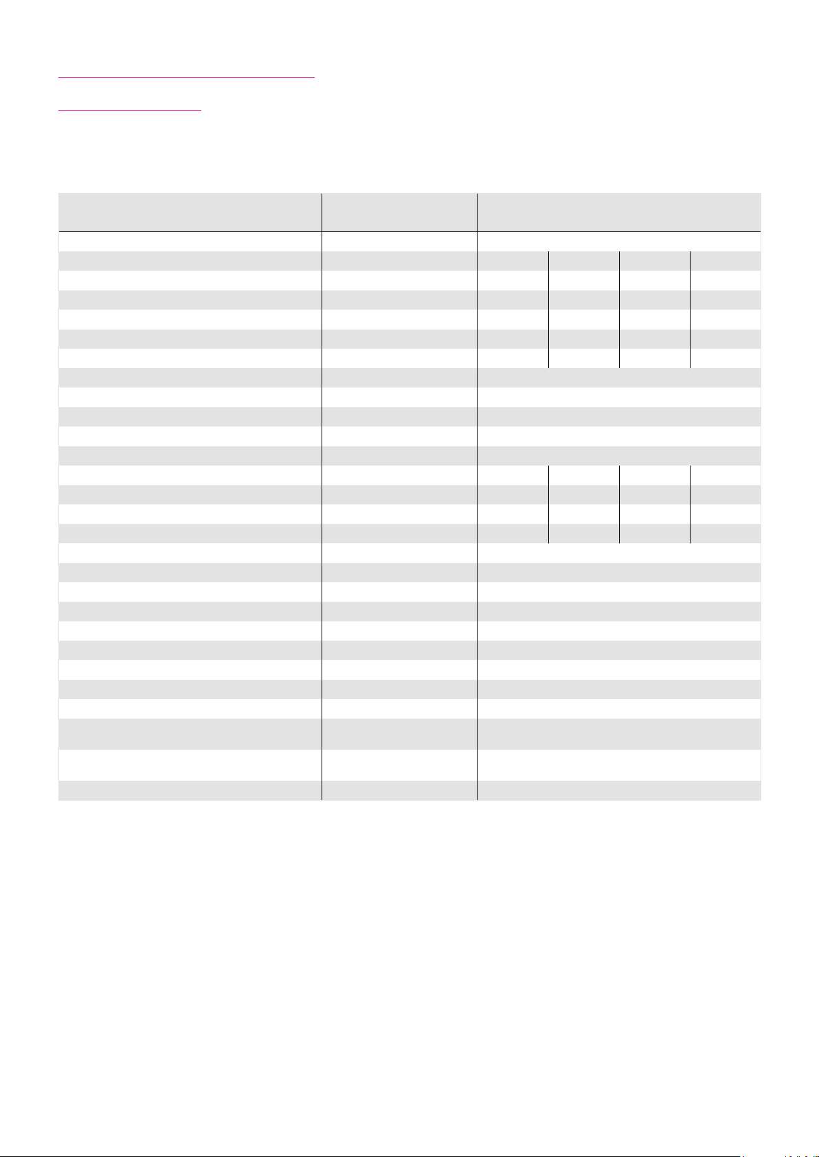
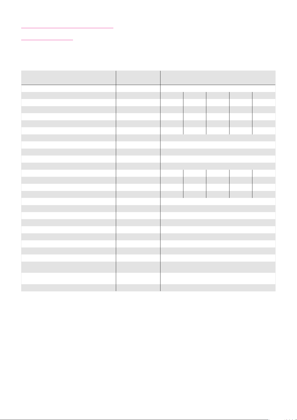
6.3.4 Performance Characteristics
The performance curves shown below are valid for the specified ambient operating temperature if the motor terminal
voltage is higher or equal to the values given in the ratings table.
Illustration 19.1 Illustration 19.2
10
9
8
7
6
5
4
Torque [Nm]
3
2
1
0
0 50 100 150 200 250 300
Speed [rpm]
Illustration 19.3 Illustration 19.4
20
15
10
Torque [Nm]
5
CHA-14A-30-H/N CHA-14A-50-H/N
20
18
16
14
12
10
8
6
Torque [Nm]
4
2
0
0 50 100 150 200
CHA-14A-80-H/N CHA-14A-100-H/N
25
20
15
10
Torque [Nm]
5
Speed [rpm]
0
0 20 40 60 80 100 120
Speed [rpm]
0
0 10 20 30 40 50 60 70 80 90 100
Speed [rpm]
Legend
Intermittent duty UM = 220 ... 430 VAC
Continuous duty
191018854 8/2018 V03
Page 20
6.4 Actuator Data CHA-17A-E
6.4.1 Technical Data
Table 20.1
Symbol
[Unit]
Motor feedback system
CHA-17A-E
RES / D2048 / M128S
Ratio i [ ] 30 50 80 100 120
Maximum output torque T
Maximum output speed n
Maximum current I
Continuous stall torque T
Continuous stall current I
Maximum DC bus voltage U
Electrical time constant (20 °C) t
Mechanical time constant (20 °C) Version RES t
Mechanical time constant (20 °C) Version D2048 t
Mechanical time constant (20 °C) Version M128S t
No load current (+20 °C) I
No load current (-20 °C) I
No load running current constant (30 °C) K
No load running current constant (80 °C) K
Torque constant (at output) k
Torque constant (at motor) k
AC voltage constant (L-L, 20 °C, at motor) k
Motor terminal voltage (fundamental wave only) U
Demagnetisation current I
Maximum motor speed n
Rated motor speed n
Resistance (L-L, 20 °C) R
Inductance (L-L) L
[Nm] 16 34 43 54 54
max
[rpm] 220 132 83 66 55
max
[A
] 8.3 10.3 8.1 8.1 6.8
max
rms
[Nm] 12 26 27 39 39
0
[A
] 6.4 8.0 5.3 6.0 5.1
0
rms
[VDC] 48
DCmax
[ms] 1.3
e
[ms] 10.0
m
[ms] 5.0
m
[ms] 9.0
m
[A
] 0.8 0.7 0.6 0.6 0.6
NLS
rms
[A
] 2.6 3.5 3.9 4.4 4.7
NLS
rms
INL
INL
[V
EM
[·10-3 A
[·10-3 A
Tout
TM
/rpm] 4.6 7.7 12.3 15.4 18.5
rms
/rpm] 1.7 2.8 4.5 5.6 6.8
rms
[Nm/A
[Nm/A
rms
E
max
N
L- L
] 1.9 3.3 5.1 6.5 7. 6
rms
] 0.07
rms
/1000 rpm] 5
[V
] 18 … 34
M
rms
[A
] -
rms
[rpm] 6600
[rpm] 3500
[Ω] 0.32
L- L
[mH] 0.42
Number of pole pairs p [ ] 5
Weight without brake m [kg]
Weight with brake m [kg]
Hollow shaft diameter d
[mm]
H
1.9 (D2048)
2.6 (RES / M128S)
2.3 (D2048)
3.0 (RES / M128S)
16
20 1018854 8/2018 V03
Page 21

6.4.2 Moment of Inertia
Table 21.1
Symbol
[Unit]
CHA-17A
Motor feedback system RES
Ratio i [ ] 30 50 80 100 120
Moment of Inertia output side
Moment of inertia without brake
Moment of inertia with brake J
[kgm²]
J
out
[kgm²] 0.104 0.289 0.741 1.158 1.667
out
0.095 0.264 0.676 1.056 1.520
Moment of Inertia at motor
Moment of inertia at motor without brake
Moment of inertia at motor with brake
J [·10
J [·10
-4
kgm²]
-4
kgm²]
1.056
1.158
Motor feedback system D2048
Ratio i [ ] 30 50 80 100 120
Moment of Inertia output side
Moment of inertia without brake
Moment of inertia with brake J
[kgm²]
J
out
[kgm²] 0.060 0.160 0.400 0.630 0.900
out
0.047 0.131 0.355 0.523 0.753
Moment of Inertia at motor
Moment of inertia at motor without brake
Moment of inertia at motor with brake
J [·10
J [·10
-4
kgm²]
-4
kgm²]
0.523
0.625
Motor feedback system M128S
Ratio i [ ] 30 50 80 100 120
Moment of Inertia output side
Moment of inertia without brake
Moment of inertia with brake J
[kgm²]
J
out
[kgm²] 0.088 0.243 0.623 0.973 1.401
out
0.078 0.218 0.557 0.871 1.254
Moment of Inertia at motor
Moment of inertia at motor without brake
Moment of inertia at motor with brake
J [·10
J [·10
-4
kgm²]
-4
kgm²]
0.871
0.973
6.4.3 Technical Data Brake
Table 21.2
Symbol
[Unit]
Ratio i [ ]
Brake voltage U
Brake holding torque (at output) T
Brake current to open I
Brake current to hold I
[VDC] 24 ±10 %
Br
[Nm] 15 25 40 50 54
Br
[ADC] -
OBr
[ADC] 0.54
HBr
30 50 80 100 120
Number of brake cyles at n = 0 rpm -
Emergency brake cyles -
Opening time t
Closing time t
[ms] -
O
[ms]
C
CHA-17A
-
211018854 8/2018 V03
Page 22
18
Drehmoment [Nm] / Torque [Nm]
-1
CHA-17A-30-E
50
Drehmoment [Nm] / Torque [Nm]
-1
CHA-17A-80-E
Drehmoment [Nm] / Torque [Nm]
Drehzahl [min-1] / Speed [rpm]
CHA-17A-120-E
40
0
Drehmoment [Nm] / Torque [Nm]
-1
CHA-17A-50-E
60
0
Drehzahl [min-1] / Speed [rpm]
CHA-17A-100-E
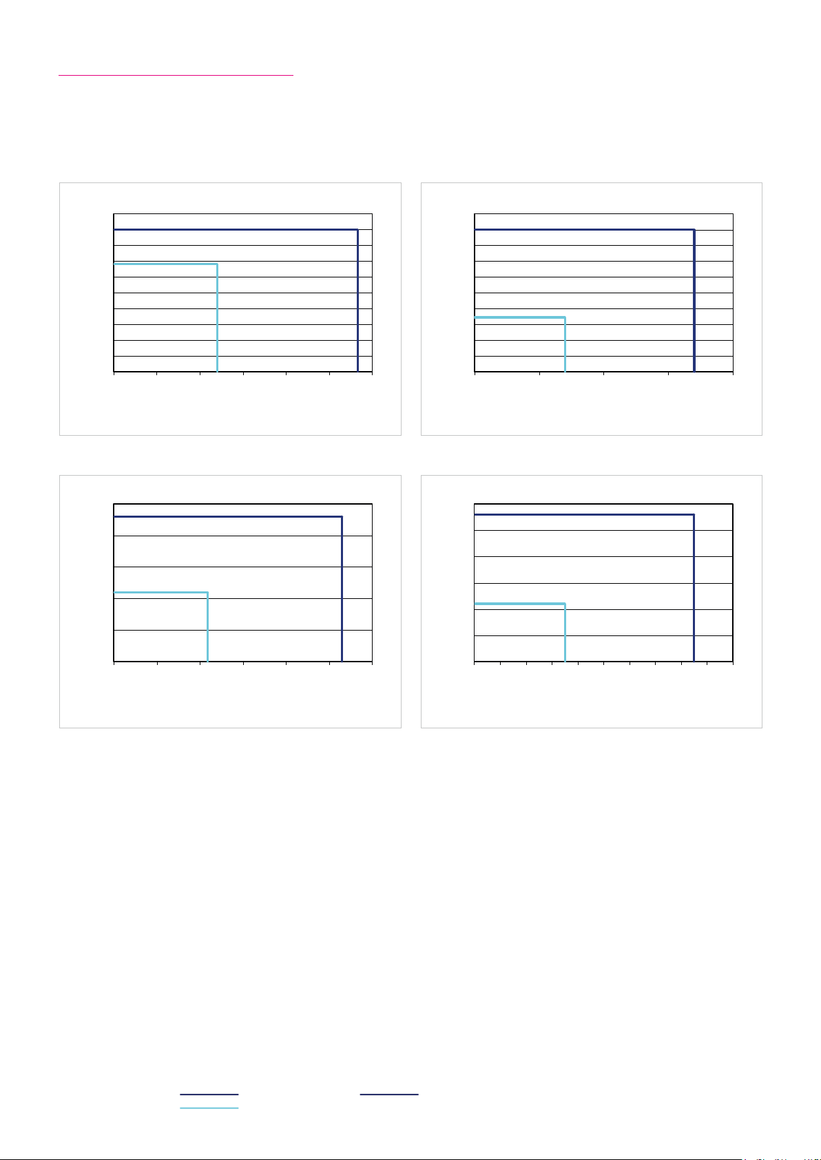
6.4.4 Performance Characteristics
The performance curves shown below are valid for the specified ambient operating temperature if the motor terminal
voltage is higher or equal to the values given in the ratings table.
Illustration 22.1 Illustration 22.2
16
14
12
10
8
Torque [Nm]
6
4
2
0
0 50 100 150 200 250 300
Speed [rpm]
Illustration 22.3 Illustration 22.4
CHA-17A-30-E CHA-17A-50-E
35
30
25
20
15
Torque [Nm]
10
5
0
0 20 40 60 80 100 120 140 16
CHA-17A-80-E CHA-17A-100-E
45
40
35
50
40
30
25
20
Torque [Nm]
15
10
30
Torque [Nm]
20
10
5
0
0 20 40 60 80 100
Speed [rpm]
0
0 10 20 30 40 50 60 70 8
Speed [rpm]
Speed [rpm]
Illustration 22.5
60
50
40
30
Torque [Nm]
20
10
0
0 10 20 30 40 50 60 70
Legend
Intermittent duty UM = 34 VAC
Continuous duty UM = 18 VAC
22 1018854 8/2018 V03
CHA-17A-120-E
Speed [rpm]
Page 23
6.5 Actuator Data CHA-17A-H/N
6.5.1 Technical Data
Table 23.1
Symbol
[Unit]
Motor feedback system
CHA-17A-H/N
RES / D2048 / M128S
Ratio i [ ] 30 50 80 100 120
Maximum output torque T
Maximum output speed n
Maximum current I
Continuous stall torque T
Continuous stall current I
Maximum DC bus voltage U
Electrical time constant (20 °C) t
Mechanical time constant (20 °C) Version RES t
Mechanical time constant (20 °C) Version D2048 t
Mechanical time constant (20 °C) Version M128S t
No load current I
No load running current constant (30 °C) K
No load running current constant (80 °C) K
Torque constant (at output) k
Torque constant (at motor) k
AC voltage constant (L-L, 20 °C, at motor) k
Motor terminal voltage (fundamental wave only) U
Demagnetisation current I
Maximum motor speed n
Rated motor speed n
Resistance (L-L, 20 °C) R
Inductance (L-L) L
[Nm] 16 34 43 54 54
max
[rpm] 243 146 91 73 61
max
[A
] 1.6 2.0 1.6 1.6 1.3
max
rms
[Nm] 12 26 27 39 39
0
[A
] 1.3 1.6 1.0 1.2 1.0
0
rms
[VDC] 680
DCmax
[ms] 2.5
e
[ms] 5.5
m
[ms] 3.0
m
[ms] 4.5
m
[A
] 0.15 0.13 0.11 0.11 0.10
NLS
rms
INL
INL
[V
EM
[·10-3 A
[·10-3 A
Tout
TM
/rpm] 1 2 3 4 5
rms
/rpm] 0.4 0.6 0.9 1 1
rms
[Nm/A
[Nm/A
rms
E
max
N
L- L
] 10.9 18.3 30.3 3 7.5 43.3
rms
] 0.37
rms
/1000 rpm] 26
[V
] 220 … 430
M
rms
[A
] -
rms
[rpm] 7300
[rpm] 3500
[Ω] 4.8
L- L
[mH] 12.0
Number of pole pairs p [ ] 5
Weight without brake m [kg]
Weight with brake m [kg]
Hollow shaft diameter d
[mm]
H
1.9 (D2048)
2.6 (RES / M128S)
2.3 (D2048)
3.0 (RES / M128S)
16
231018854 8/2018 V03
Page 24

6.5.2 Moment of Inertia
Table 24.1
Symbol
[Unit]
CHA-17A
Motor feedback system RES
Ratio i [ ] 30 50 80 100 120
Moment of Inertia output side
Moment of inertia without brake
Moment of inertia with brake J
[kgm²]
J
out
[kgm²] 0.104 0.289 0.741 1.158 1.667
out
0.095 0.264 0.676 1.056 1.520
Moment of Inertia at motor
Moment of inertia at motor without brake
Moment of inertia at motor with brake
J [·10
J [·10
-4
kgm²]
-4
kgm²]
1.056
1.158
Motor feedback system D2048
Ratio i [ ] 30 50 80 100 120
Moment of Inertia output side
Moment of inertia without brake
Moment of inertia with brake J
[kgm²]
J
out
[kgm²] 0.060 0.160 0.400 0.630 0.900
out
0.047 0.131 0.355 0.523 0.753
Moment of Inertia at motor
Moment of inertia at motor without brake
Moment of inertia at motor with brake
J [·10
J [·10
-4
kgm²]
-4
kgm²]
0.523
0.625
Motor feedback system M128S
Ratio i [ ] 30 50 80 100 120
Moment of Inertia output side
Moment of inertia without brake
Moment of inertia with brake J
[kgm²]
J
out
[kgm²] 0.088 0.243 0.623 0.973 1.401
out
0.078 0.218 0.557 0.871 1.254
Moment of Inertia at motor
Moment of inertia at motor without brake
Moment of inertia at motor with brake
J [·10
J [·10
-4
kgm²]
-4
kgm²]
0.871
0.973
6.5.3 Technical Data Brake
Table 24.2
Symbol
[Unit]
Ratio i [ ]
Brake voltage U
Brake holding torque (at output) T
Brake current to open I
Brake current to hold I
[VDC] 24 ±10 %
Br
[Nm] 15 25 40 50 54
Br
[ADC] -
OBr
[ADC] 0.54
HBr
30 50 80 100 120
Number of brake cyles at n = 0 rpm -
Emergency brake cyles -
Opening time t
Closing time t
[ms] -
O
[ms]
C
CHA-17A
-
24 1018854 8/2018 V03
Page 25

18
CHA-17A-30-H/L
50
100
CHA-17A-80-H/L
60
80
CHA-17A-120-H/L
40
160
Drehmoment [Nm] / Torque [Nm]
CHA-17A-50-H/L
60
80
CHA-17A-100-H/L
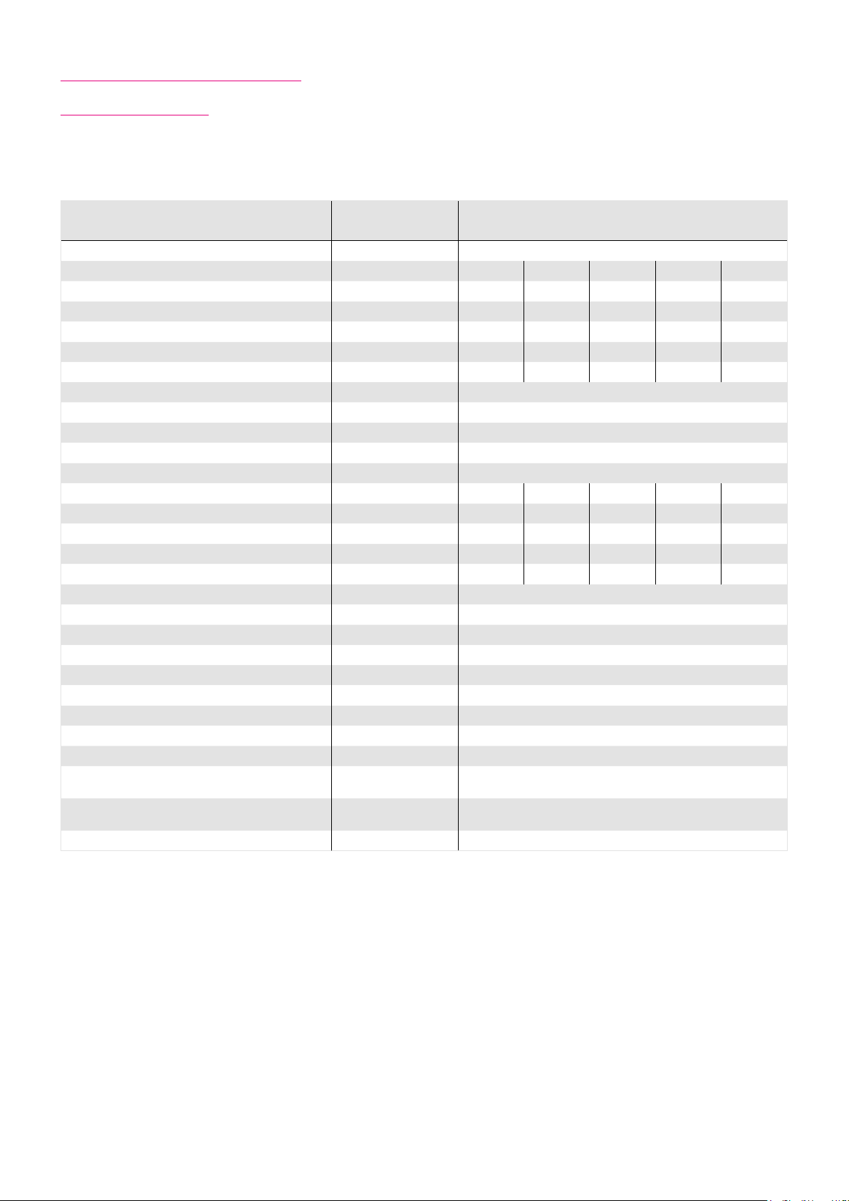
6.5.4 Performance Characteristics
The performance curves shown below are valid for the specified ambient operating temperature if the motor terminal
voltage is higher or equal to the values given in the ratings table.
Illustration 25.1 Illustration 25.2
16
14
12
10
8
6
Torque [Nm]
4
2
0
0 50 100 150 200 250 300
Speed [rpm]
Illustration 25.3 Illustration 25.4
45
40
35
30
25
20
Torque [Nm]
15
10
5
0
0 20 40 60 80
CHA-17A-30-H/N CHA-17A-50-H/N
35
30
25
20
15
Torque [Nm]
10
5
0
0 20 40 60 80 100 120 140
CHA-17A-80-H/N CHA-17A-100-H/N
50
40
30
20
Torque [Nm]
10
0
0 10 20 30 40 50 60 70
Speed [rpm]
Speed [rpm]
Illustration 25.5
50
40
30
Torque [Nm]
20
10
0
0 10 20 30 40 50 60 70
Speed [rpm]
Legend
Intermittent duty UM = 220 ... 430 VAC
Continuous duty
CHA-17A-120-H/N
Speed [rpm]
251018854 8/2018 V03
Page 26
6.6 Actuator Data CHA-20A-C1024
6.6.1 Technical Data
Table 26.1
Symbol
[Unit]
CHA-20A
Motor feedback system C1024
Ratio i [ ] 30 50 80 100 120 160
Maximum output torque T
Maximum output speed n
Maximum current I
Continuous stall torque T
Continuous stall current I
Maximum DC bus voltage U
Electrical time constant (20 °C) t
Mechanical time constant (20 °C) t
No load current I
No load running current constant (30 °C) K
No load running current constant (80 °C) K
Torque constant (at output) k
Torque constant (at motor) k
AC voltage constant (L-L, 20 °C, at motor) k
Motor terminal voltage (fundamental wave only) U
Demagnetisation current I
Maximum motor speed n
Rated motor speed n
Resistance (L-L, 20 °C) R
Inductance (L-L) L
[Nm] 27 56 74 82 87 92
max
[rpm] 200 120 75 60 50 38
max
[A
] 2.9 3.8 3.1 2.8 2.5 2.1
max
rms
[Nm] 19 32 47 49 49 49
0
[A
] 2.1 2.1 1.9 1.6 1.4 1.0
0
rms
[VDC] 680
DCmax
[ms] 1.4
e
[ms] 6.7
m
[A
] 0.19 0.17 0.14 0.14 0.13 0.13
NLS
rms
INL
INL
[V
EM
[·10-3 A
[·10-3 A
Tout
/rpm] 2 4 7 8 9 12
rms
/rpm] 0.7 2 2 3 4 5
rms
[Nm/A
[Nm/A
TM
rms
E
max
N
L- L
] 9.9 16.5 26.8 33.4 40.1 53.5
rms
] 0.36
rms
/1000 rpm] 23
[V
] 220 … 430
M
rms
[A
] 7.0
rms
[rpm] 6000
[rpm] 3500
[Ω] 5.9
L- L
[mH] 8.0
Number of pole pairs p [ ] 5
Weight without brake m [kg] 3.2
Weight with brake m [kg] 3.9
Hollow shaft diameter d
[mm] 18
H
6.6.2 Moment of Inertia
Table 26.2
Symbol
[Unit]
CHA-20A
Motor feedback system C1024
Ratio i [ ] 30 50 80 100 120 160
Moment of Inertia output side
Moment of inertia without brake J
Moment of inertia with brake J
[kgm²] 0.1 0.28 0.72 1.12 1.61 2.86
out
[kgm²] 0.13 0.35 0.89 1.39 2.00 3.50
out
Moment of Inertia at motor
-4
Moment of inertia at motor without brake J [·10
Moment of inertia at motor with brake J [·10
kgm²] 1.12
-4
kgm²] 1.39
6.6.3 Technical Data Brake
Table 26.3
Symbol
[Unit]
Ratio i [ ] 30 50 80 100 120 160
Brake voltage U
Brake holding torque (at output) T
Brake current to open I
Brake current to hold I
[VDC] 24 ±10 %
Br
[Nm] 27 45 72 82 87 92
Br
[ADC] 0.6
OBr
[ADC] 0.3
HBr
Number of brake cyles at n = 0 rpm 10000000
Emergency brake cyles 200
Opening time t
Closing time t
[ms] 110
O
[ms] 70
C
CHA-20A
26 1018854 8/2018 V03
Page 27
30
250
CHA-20A-30
80
Drehmoment [Nm] /
CHA-20A-80
60
140
CHA-20A-50
90
70
CHA-20A-100
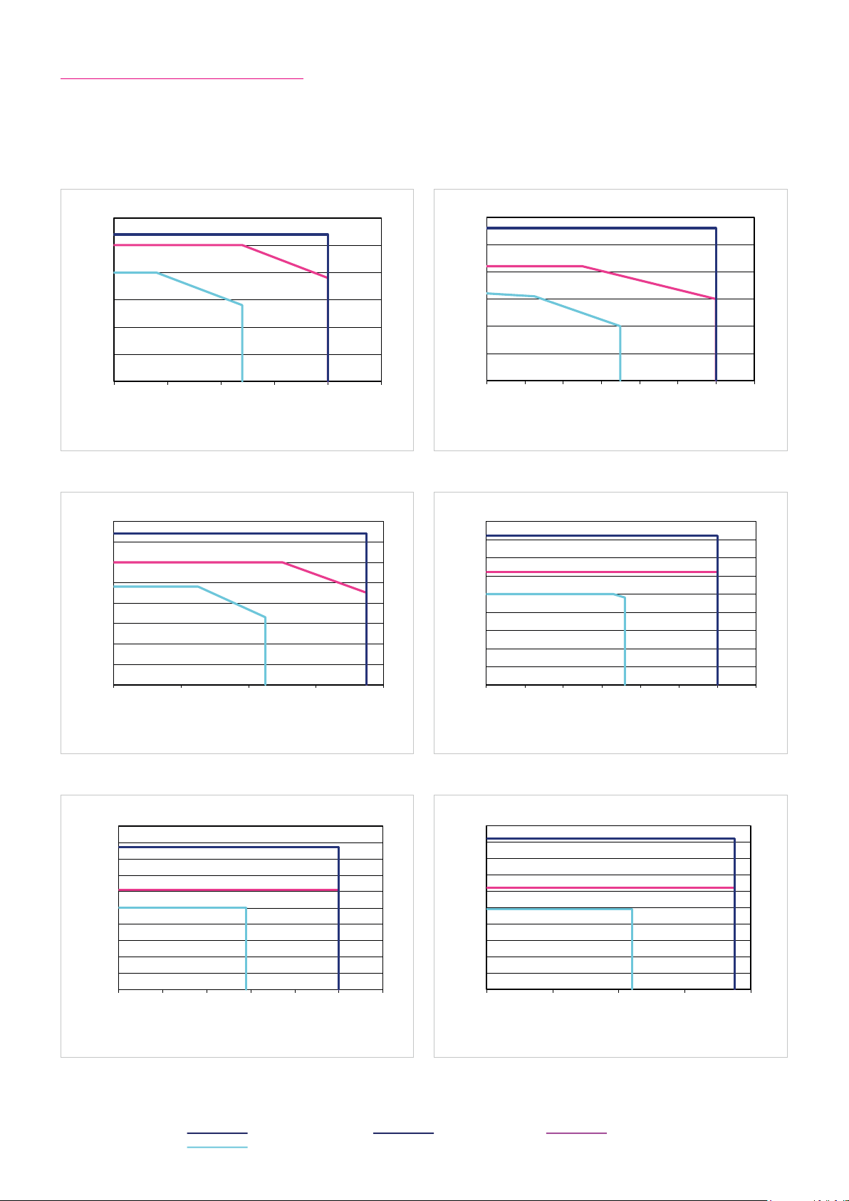
6.6.4 Performance Characteristics
100
60
Drehmoment [Nm] / Torque [Nm]
CHA-20A-120
40
CHA-20A-160
The performance curves shown below are valid for the specified ambient operating temperature if the motor terminal
voltage is higher or equal to the values given in the ratings table.
Illustration 27.1 Illustration 27.2
25
20
15
10
5
0
0 50 100 150 200
Speed [rpm]
Illustration 27.3 Illustration 27.4
70
60
50
Torque [Nm]
40
30
Torque [Nm] Torque [Nm]
20
10
0
0 20 40 60 80
CHA-20A-30 CHA-20A-50
50
40
30
20
Torque [Nm]
10
0
0 20 40 60 80 100 120
CHA-20A-80 CHA-20A-100
80
70
60
50
40
30
Torque [Nm]
20
10
0
0 10 20 30 40 50 60
Speed [rpm]
Speed [rpm]
Illustration 27.5 Illustration 27.6
90
80
70
60
50
40
Torque [Nm]
30
20
10
0
0 10 20 30 40 50
Speed [rpm]
CHA-20A-120 CHA-20A-160
100
90
80
70
60
50
40
Torque [Nm]
30
20
10
0
0 10 20 30
Legend
Intermittent duty UM = 220 ... 430 VAC S3-ED 50 % (1 min)
Continuous duty
Speed [rpm]
Speed [rpm]
271018854 8/2018 V03
Page 28

6.7 Actuator Data CHA-25A-C1024
6.7.1 Technical Data
Table 28.1
Symbol
[Unit]
CHA-25A
Motor feedback system C1024
Ratio i [ ] 30 50 80 100 120 160
Maximum output torque T
Maximum output speed n
Maximum current I
Continuous stall torque T
Continuous stall current I
Maximum DC bus voltage U
Electrical time constant (20 °C) t
Mechanical time constant (20 °C) t
No load current I
No load running current constant (30 °C) K
No load running current constant (80 °C) K
Torque constant (at output) k
Torque constant (at motor) k
AC voltage constant (L-L, 20 °C, at motor) k
Motor terminal voltage (fundamental wave only) U
Demagnetisation current I
Maximum motor speed n
Rated motor speed n
Resistance (L-L, 20 °C) R
Inductance (L-L) L
[Nm] 50 98 137 157 167 176
max
[rpm] 187 112 70 56 47 35
max
[A
] 3.5 4.0 3.4 3.2 2.8 2.2
max
rms
[Nm] 38 55 87 108 108 108
0
[A
] 2.7 2.3 2.2 2.2 1.9 1.4
0
rms
[VDC] 680
DCmax
[ms] 1.6
e
[ms] 5.9
m
[A
] 0.21 0.19 0.15 0.1 5 0.15 0.1 4
NLS
rms
INL
INL
[V
EM
[·10-3 A
[·10-3 A
Tout
/rpm] 4 6 10 12 14 19
rms
/rpm] 1 2 3 4 5 7
rms
[Nm/A
[Nm/A
TM
rms
E
max
N
L- L
] 15.5 26.0 42.5 53.1 63.9 85.0
rms
] 0.55
rms
/1000 rpm] 37
[V
] 220 … 430
M
rms
[A
] 15
rms
[rpm] 5600
[rpm] 3500
[Ω] 3.7
L- L
[mH] 6.0
Number of pole pairs p [ ] 6
Weight without brake m [kg] 4.9
Weight with brake m [kg] 6.1
Hollow shaft diameter d
[mm] 27
H
6.7.2 Moment of Inertia
Table 28.2
Symbol
[Unit]
CHA-25A
Motor feedback system C1024
Ratio i [ ] 30 50 80 100 120 160
Moment of Inertia output side
Moment of inertia without brake J
Moment of inertia with brake J
[kgm²] 0.29 0.80 2.0 3.2 4.6 8.1
out
[kgm²] 0.35 0.97 2.5 3.9 5.6 9.9
out
Moment of Inertia at motor
-4
Moment of inertia at motor without brake J [·10
Moment of inertia at motor with brake J [·10
kgm²] 3.2
-4
kgm²] 3.9
6.7.3 Technical Data Brake
Table 28.3
Symbol
[Unit]
Ratio i [ ] 30 50 80 100 120 160
Brake voltage U
Brake holding torque (at output) T
Brake current to open I
Brake current to hold I
[VDC] 24 ±10 %
Br
[Nm] 54 90 137 157 167 176
Br
[ADC] 0.9
OBr
[ADC] 0.4
HBr
Number of brake cyles at n = 0 rpm 10000000
Emergency brake cyles 200
Opening time t
Closing time t
[ms] 110
O
[ms] 70
C
28 1018854 8/2018 V03
CHA-25A
Page 29

60
CHA-25A-30
08-A52-AHCneinilnneksbeirtnA nov gnunhcereB
CHA-25A-80
021-A52-AHCneinilnneksbeirtnA nov gnunhcereB
180
50
Drehmoment [Nm] /
CHA-25A-120
05-A52-AHCneinilnneksbeirtnA nov gnunhcereB
CHA-25A-50
001-A52-AHCneinilnneksbeirtnA nov gnunhcereB
180
CHA-25A-100
200
Drehmoment [Nm] / Torque [Nm]
CHA-25A-160
6.7.4 Performance Characteristics
The performance curves shown below are valid for the specified ambient operating temperature if the motor terminal
voltage is higher or equal to the values given in the ratings table.
Illustration 29.1 Illustration 29.2
50
40
30
20
10
0
0 50 100 150 200
Speed [rpm]
Illustration 29.3 Illustration 29.4
160
140
120
100
80
60
Torque [Nm] Torque [Nm]Torque [Nm]
40
20
0
0 20 40 60 80
Speed [rpm]
CHA-25A-30 CHA-25A-50
120
100
80
60
Torque [Nm]
40
20
0
0 20 40 60 80 100 120
CHA-25A-80 CHA-25A-100
160
140
120
100
80
Torque [Nm]
60
40
20
0
0 10 20 30 40 50 60
Speed [rpm]
Speed [rpm]
Illustration 29.5 Illustration 29.6
Legend
Intermittent duty UM = 430 VAC S3-ED 50 % (1 min)
Continuous duty UM = 220 VAC
160
140
120
100
Torque [Nm]
80
60
40
20
0
0 10 20 30 40
Speed [rpm]
CHA-25A-120 CHA-25A-160
180
160
140
120
100
80
Torque [Nm]
60
40
20
0
0 10 20 30 40
Speed [rpm]
291018854 8/2018 V03
Page 30

6.8 Actuator Data CHA-32A-C1024
6.8.1 Technical Data
Table 30.1
Symbol
[Unit]
CHA-32A
Motor feedback system C1024
Ratio i [ ] 30 50 80 100 120 160
Maximum output torque T
Maximum output speed n
Maximum current I
Continuous stall torque T
Continuous stall current I
Maximum DC bus voltage U
Electrical time constant (20 °C) t
Mechanical time constant (20 °C) t
No load current I
No load running current constant (30 °C) K
No load running current constant (80 °C) K
Torque constant (at output) k
Torque constant (at motor) k
AC voltage constant (L-L, 20 °C, at motor) k
Motor terminal voltage (fundamental wave only) U
Demagnetisation current I
Maximum motor speed n
Rated motor speed n
Resistance (L-L, 20 °C) R
Inductance (L-L) L
[Nm] 100 216 304 333 353 372
max
[rpm] 160 96 60 48 40 30
max
[A
] 7.1 9.8 8.3 7. 2 6.3 5.3
max
rms
[Nm] 44 71 119 154 179 216
0
[A
] 3.2 3.2 3.2 3.2 3.2 2.9
0
rms
[VDC] 680
DCmax
[ms] 1.6
e
[ms] 7.1
m
[A
] 0.30 0.30 0.20 0.20 0.20 0.18
NLS
rms
INL
INL
[V
EM
[·10-3 A
[·10-3 A
Tout
/rpm] 6 10 17 21 25 34
rms
/rpm] 2 3 6 7 8 11
rms
[Nm/A
[Nm/A
TM
rms
E
max
N
L- L
] 15.5 25.9 42.1 52.5 63.0 84.5
rms
] 0.55
rms
/1000 rpm] 37
[V
] 220 … 430
M
rms
[A
] 15
rms
[rpm] 4800
[rpm] 3500
[Ω] 3.7
L- L
[mH] 6.0
Number of pole pairs p [ ] 6
Weight without brake m [kg] 6.6
Weight with brake m [kg] 7.8
Hollow shaft diameter d
[mm] 32
H
6.8.2 Moment of Inertia
Table 30.2
Symbol
[Unit]
CHA-32A
Motor feedback system C1024
Ratio i [ ] 30 50 80 100 120 160
Moment of Inertia output side
Moment of inertia without brake J
Moment of inertia with brake J
[kgm²] 0.44 1.22 3.1 4.9 7. 1 12.5
out
[kgm²] 0.53 1.47 3.8 5.9 8.5 15.0
out
Moment of Inertia at motor
-4
Moment of inertia at motor without brake J [·10
Moment of inertia at motor with brake J [·10
kgm²] 4.9
-4
kgm²] 5.9
6.8.3 Technical Data Brake
Table 30.3
Symbol
[Unit]
Ratio i [ ] 30 50 80 100 120 160
Brake voltage U
Brake holding torque (at output) T
Brake current to open I
Brake current to hold I
[VDC] 24 ±10 %
Br
[Nm] 54 90 144 180 216 288
Br
[ADC] 0.9
OBr
[ADC] 0.4
HBr
Number of brake cyles at n = 0 rpm 10000000
Emergency brake cyles 200
Opening time t
Closing time t
[ms] 110
O
[ms] 70
C
30 1018854 8/2018 V03
CHA-32A
Page 31

03-A23-AHCneinilnneksbeirtnA nov gnunhcereB
CHA-32A-30
08-A23-AHCneinilnneksbeirtnA nov gnunhcereB
70
Drehmoment [Nm] / Torque [Nm]
CHA-32A-80
021-A23-AHCneinilnneksbeirtnA nov gnunhcereB
400
CHA-32A-120
05-A23-AHCneinilnneksbeirtnA nov gnunhcereB
250
CHA-32A-50
001-A23-AHCneinilnneksbeirtnA nov gnunhcereB
350
CHA-32A-100
061-A23-AHCneinilnneksbeirtnA nov gnunhcereB
400
CHA-32A-160
6.8.4 Performance Characteristics
The performance curves shown below are valid for the specified ambient operating temperature if the motor terminal
voltage is higher or equal to the values given in the ratings table.
Illustration 31.1 Illustration 31.2
120
100
80
60
Torque [Nm]
40
20
0
0 50 100 150 200
Speed [rpm]
Illustration 31.3 Illustration 31.4
350
300
250
200
150
Torque [Nm]
100
50
0
0 10 20 30 40 50 60
Speed [rpm]
CHA-32A-30 CHA-32A-50
200
150
100
Torque [Nm]
50
0
0 20 40 60 80 100 120
CHA-32A-80 CHA-32A-100
300
250
200
150
Torque [Nm]Torque [Nm]
100
50
0
0 10 20 30 40 50 60
Speed [rpm]
Speed [rpm]
Illustration 31.5 Illustration 31.6
350
300
250
200
150
Torque [Nm]
100
50
0
0 10 20 30 40 50
Speed [rpm]
Legend
Intermittent duty UM = 430 VAC S3-ED 50 % (1 min)
Continuous duty UM = 220 VAC
CHA-32A-120 CHA-32A-160
350
300
250
200
150
100
50
0
0 5 10 15 20 25 30 35
Speed [rpm]
311018854 8/2018 V03
Page 32
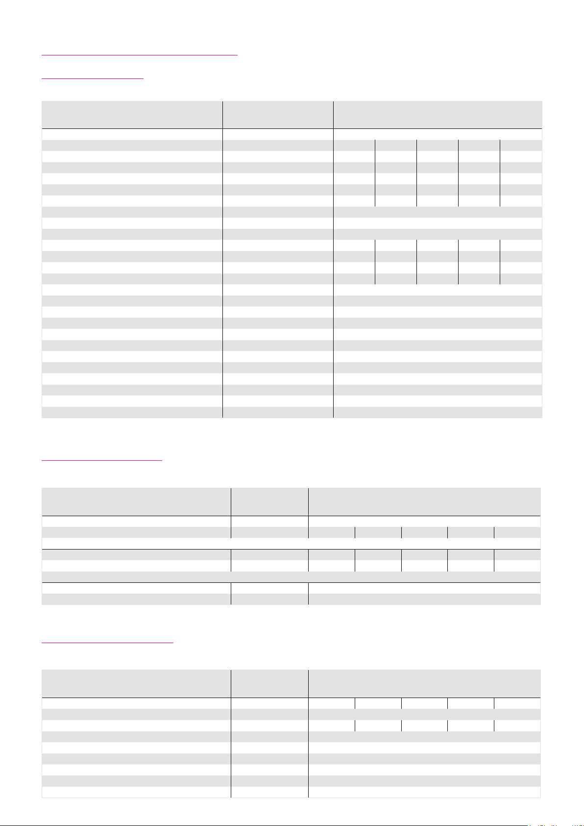
6.9 Actuator Data CHA-40A-C1024
6.9.1 Technical Data
Table 32.1
Symbol
[Unit]
CHA-40A
Motor feedback system C1024
Ratio i [ ] 50 80 100 120 160
Maximum output torque T
Maximum output speed n
Maximum current I
Continuous stall torque T
Continuous stall current I
Maximum DC bus voltage U
Electrical time constant (20 °C) t
Mechanical time constant (20 °C) t
No load current I
No load running current constant (30 °C) K
No load running current constant (80 °C) K
Torque constant (at output) k
Torque constant (at motor) k
AC voltage constant (L-L, 20 °C, at motor) k
Motor terminal voltage (fundamental wave only) U
Demagnetisation current I
Maximum motor speed n
Rated motor speed n
Resistance (L-L, 20 °C) R
Inductance (L-L) L
[Nm] 402 519 568 617 647
max
[rpm] 80 50 40 33 25
max
[A
] 11.8 9.2 8.1 7. 3 5.9
max
rms
[Nm] 125 208 260 314 420
0
[A
] 3.6 3.6 3.6 3.6 3.6
0
rms
[VDC] 680
DCmax
[ms] 2.1
e
[ms] 6.8
m
[A
] 0.30 0.20 0.20 0.20 0.20
NLS
rms
INL
INL
[V
EM
[·10-3 A
[·10-3 A
Tout
/rpm] 13 20 25 30 40
rms
/rpm] 4 6 8 10 13
rms
[Nm/A
[Nm/A
TM
rms
E
max
N
L- L
] 38 62 77 92 123
rms
] 0.83
rms
/1000 rpm] 53
[V
] 220 … 430
M
rms
[A
] 18
rms
[rpm] 4000
[rpm] 3000
[Ω] 2.9
L- L
[mH] 6.0
Number of pole pairs p [ ] 6
Weight without brake m [kg] 11.7
Weight with brake m [kg] 13.8
Hollow shaft diameter d
[mm] 39
H
6.9.2 Moment of Inertia
Table 32.2
Symbol
[Unit]
CHA-40A
Motor feedback system C1024
Ratio i [ ] 50 80 100 120 160
Moment of Inertia output side
Moment of inertia without brake J
Moment of inertia with brake J
[kgm²] 3.10 7.90 12.3 17.7 31.4
out
[kgm²] 3.60 9.10 14.2 20.4 36.3
out
Moment of Inertia at motor
-4
Moment of inertia at motor without brake J [·10
Moment of inertia at motor with brake J [·10
kgm²] 12.3
-4
kgm²] 14.2
6.9.3 Technical Data Brake
Table 32.3
Symbol
[Unit]
Ratio i [ ] 50 80 100 120 160
Brake voltage U
Brake holding torque (at output) T
Brake current to open I
Brake current to hold I
[VDC] 24 ±10 %
Br
[Nm] 225 360 450 540 647
Br
[ADC] 0.7
OBr
[ADC] 0.3
HBr
Number of brake cyles at n = 0 rpm 10000000
Emergency brake cyles 200
Opening time t
Closing time t
[ms] 110
O
[ms] 70
C
32 1018854 8/2018 V03
CHA-40A
Page 33

05-A04-AHCneinilnneksbeirtnA nov gnunhcereB
Drehmoment [Nm] /
CHA-40A-50
001-A04-AHCneinilnneksbeirtnA nov gnunhcereB
600
Drehmoment [Nm] / Torque [Nm]
CHA-40A-100
061-A04-AHCneinilnneksbeirtnA nov gnunhcereB
700
CHA-40A-160
08-A04-AHCneinilnneksbeirtnA nov gnunhcereB
Drehmoment [Nm] /
CHA-40A-80
021-A04-AHCneinilnneksbeirtnA nov gnunhcereB
700
Drehmoment [Nm] /
CHA-40A-120
6.9.4 Performance Characteristics
The performance curves shown below are valid for the specified ambient operating temperature if the motor terminal
voltage is higher or equal to the values given in the ratings table.
Illustration 33.1 Illustration 33.2
450
400
CHA-40A-50 CHA-40A-80
600
500
350
300
250
Torque [Nm]
400
Torque [Nm]
300
200
150
100
200
100
50
0
0 20 40 60 80 100
Drehzahl [min
Illustration 33.3 Illustration 33.4
500
400
300
-1
] / Speed [rpm]
Speed [rpm]
CHA-40A-100 CHA-40A-120
0
0 10 20 30 40 50 60
600
500
400
Torque [Nm]
300
Torque [Nm] Torque [Nm]Torque [Nm]
200
100
0
0 10 20 30 40 50
Drehzahl [min-1] / Speed [rpm]
Speed [rpm]
Torque [Nm] Torque [Nm]
200
100
0
0 5 10 15 20 25 30 35
Drehzahl [min-1] / Speed [rpm]
Drehzahl [min-1] /
Speed [rpm]
Speed [rpm]
Illustration 33.5
Legend
Intermittent duty UM = 430 VAC S3-ED 50 % (1 min)
Continuous duty UM = 220 VAC
CHA-40A-160
600
500
400
300
200
100
0
0 5 10 15 20 25 30
Speed [rpm]
331018854 8/2018 V03
Page 34
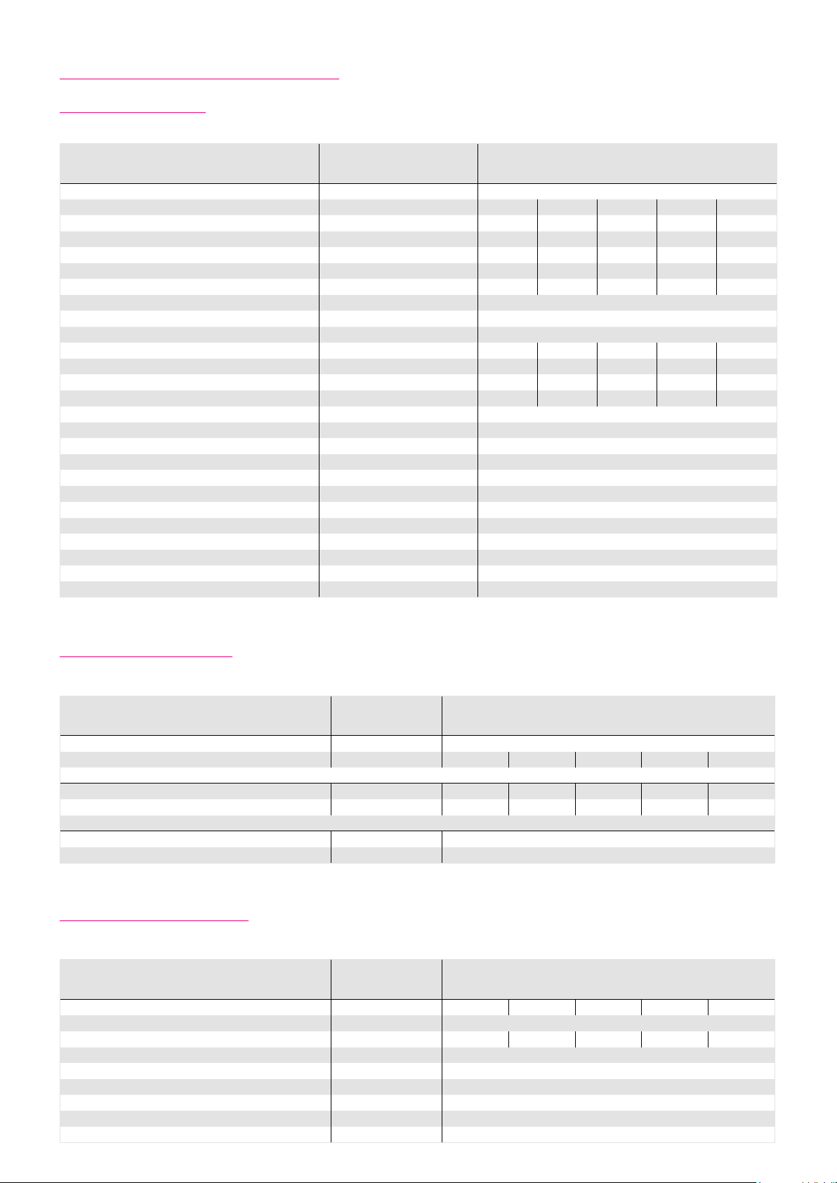
6.10 Actuator Data CHA-50A-C1024
6.10.1 Technical Data
Table 34.1
Symbol
[Unit]
CHA-50A
Motor feedback system C1024
Ratio i [ ] 50 80 100 120 160
Maximum output torque T
Maximum output speed n
Maximum current I
Continuous stall torque T
Continuous stall current I
Maximum DC bus voltage U
Electrical time constant (20 °C) t
Mechanical time constant (20 °C) t
No load current I
No load running current constant (30 °C) K
No load running current constant (80 °C) K
Torque constant (at output) k
Torque constant (at motor) k
AC voltage constant (L-L, 20 °C, at motor) k
Motor terminal voltage (fundamental wave only) U
Demagnetisation current I
Maximum motor speed n
Rated motor speed n
Resistance (L-L, 20 °C) R
Inductance (L-L) L
[Nm] 715 941 980 1080 1180
max
[rpm] 70 44 35 30 22
max
[A
] 10.2 8.3 6.9 6.4 5.3
max
rms
[Nm] 194 363 456 550 736
0
[A
] 2.9 3.2 3.2 3.2 3.1
0
rms
[VDC] 680
DCmax
[ms] 3.4
e
[ms] 4.7
m
[A
] 0.30 0.20 0.20 0.17 0.1 6
NLS
rms
INL
INL
[V
EM
[·10-3 A
[·10-3 A
Tout
/rpm] 12 20 25 29 39
rms
/rpm] 4 6 8 9 12
rms
[Nm/A
[Nm/A
TM
rms
E
max
N
L- L
] 74 121 145 181 242
rms
] 1.60
rms
/1000 rpm] 104
[V
] 220 … 430
M
rms
[A
] 18
rms
[rpm] 3500
[rpm] 2500
[Ω] 3.5
L- L
[mH] 12
Number of pole pairs p [ ] 6
Weight without brake m [kg] 19.9
Weight with brake m [kg] 23.5
Hollow shaft diameter d
[mm] 45
H
6.10.2 Moment of Inertia
Table 34.2
Symbol
[Unit]
CHA-50A
Motor feedback system C1024
Ratio i [ ] 50 80 100 120 160
Moment of Inertia output side
Moment of inertia without brake J
Moment of inertia with brake J
[kgm²] 6.62 16.90 26.5 3 8.1 67.8
out
[kgm²] 7.3 0 18.70 29.2 42.0 74.7
out
Moment of Inertia at motor
Moment of inertia at motor without brake J [·10
Moment of inertia at motor with brake J [·10
-4
kgm²] 26.5
-4
kgm²] 29.2
6.10.3 Technical Data Brake
Table 34.3
Symbol
[Unit]
Ratio i [ ] 50 80 100 120 160
Brake voltage U
Brake holding torque (at output) T
Brake current to open I
Brake current to hold I
[VDC] 24 ±10 %
Br
[Nm] 225 360 450 540 720
Br
[ADC] 0.7
OBr
[ADC] 0.3
HBr
Number of brake cyles at n = 0 rpm 10000000
Emergency brake cyles 200
Opening time t
Closing time t
[ms] 110
O
[ms] 70
C
34 1018854 8/2018 V03
CHA-50A
Page 35
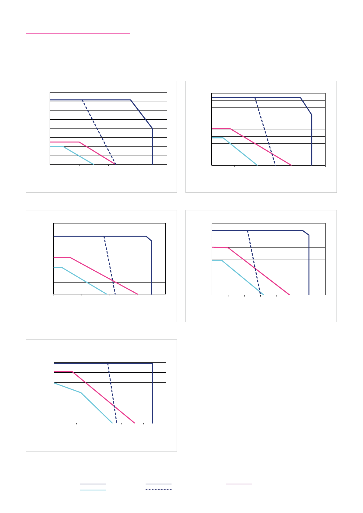
05-A05-AHCneinilnneksbeirtnA nov gnunhcereB
800
Drehmoment [Nm] /
CHA-50A-50
001-A05-AHCneinilnneksbeirtnA nov gnunhcereB
1200
Drehmoment [Nm] / Torque [Nm]
CHA-50A-100
061-A05-AHCneinilnneksbeirtnA nov gnunhcereB
Drehmoment [Nm] / Torque [Nm]
Drehzahl [min-1Speed [rpm]
CHA-50A-160
08-A05-AHCneinilnneksbeirtnA nov gnunhcereB
Drehmoment [Nm] / Torque [Nm]
CHA-50A-80
021-A05-AHCneinilnneksbeirtnA nov gnunhcereB
1200
Drehmoment [Nm] /
CHA-50A-120
6.10.4 Performance Characteristics
The performance curves shown below are valid for the specified ambient operating temperature if the motor terminal
voltage is higher or equal to the values given in the ratings table.
Illustration 35.1 Illustration 35.2
CHA-50A-50 CHA-50A-80
1000
700
600
500
Torque [Nm]
400
300
Torque [Nm]
200
100
0
0 20 40 60 80
Speed [rpm]
Illustration 35.3 Illustration 35.4
1000
800
CHA-50A-100 CHA-50A-120
900
800
700
600
500
400
300
200
100
0
0 10 20 30 40 50
1000
800
Drehzahl [min-1] / Speed [rpm]
Speed [rpm]
Torque [Nm]
Illustration 35.5
1400
1200
1000
Torque [Nm]
600
400
200
0
0 10 20 30 40
Drehzahl [min-1] / Speed [rpm]
Speed [rpm]
CHA-50A-160
800
600
400
200
0
0 5 10 15 20 25
Speed [rpm]
Torque [Nm]
600
Torque [Nm] Torque [Nm]
400
200
0
0 5 10 15 20 25 30 35
Drehzahl [min-1] / Speed [rpm]
Speed [rpm]
Legend
Intermittent duty UM = 430 VAC S3-ED 50 % (1 min)
Continuous duty UM = 220 VAC
351018854 8/2018 V03
Page 36

6.11 Actuator Data CHA-58A-C1024
6.11.1 Technical Data
Table 36.1
Symbol
[Unit]
CHA-58A
Motor feedback system C1024
Ratio i [ ] 50 80 100 120 160
Maximum output torque T
Maximum output speed n
Maximum current I
Continuous stall torque T
Continuous stall current I
Maximum DC bus voltage U
Electrical time constant (20 °C) t
Mechanical time constant (20 °C) t
No load current I
No load running current constant (30 °C) K
No load running current constant (80 °C) K
Torque constant (at output) k
Torque constant (at motor) k
AC voltage constant (L-L, 20 °C, at motor) k
Motor terminal voltage (fundamental wave only) U
Demagnetisation current I
Maximum motor speed n
Rated motor speed n
Resistance (L-L, 20 °C) R
Inductance (L-L) L
[Nm] 1020 1480 1590 1720 1840
max
[rpm] 60 38 30 25 19
max
[A
] 1 4.4 12.8 11.1 10.0 8.1
max
rms
[Nm] 280 532 670 805 1080
0
[A
] 4.2 4.6 4.6 4.6 4.6
0
rms
[VDC] 680
DCmax
[ms] 3.5
e
[ms] 5 .4
m
[A
] 0.40 0.28 0.26 0.25 0.23
NLS
rms
INL
INL
[V
EM
[·10-3 A
[·10-3 A
Tout
/rpm] 19 30 38 46 61
rms
/rpm] 6 10 12 15 19
rms
[Nm/A
[Nm/A
TM
rms
E
max
N
L- L
] 75 122 152 183 244
rms
] 1.70
rms
/1000 rpm] 105
[V
] 220 … 430
M
rms
[A
] 25
rms
[rpm] 3000
[rpm] 2000
[Ω] 2.4
L- L
[mH] 9
Number of pole pairs p [ ] 6
Weight without brake m [kg] 2 7.2
Weight with brake m [kg] 31
Hollow shaft diameter d
[mm] 45
H
6.11.2 Moment of Inertia
Table 36.2
Symbol
[Unit]
CHA-58A
Motor feedback system C1024
Ratio i [ ] 50 80 100 120 160
Moment of Inertia output side
Moment of inertia without brake J
Moment of inertia with brake J
[kgm²] 11.6 29.8 46.6 6 7.1 119
out
[kgm²] 11.8 30.3 47.3 68.1 121
out
Moment of Inertia at motor
Moment of inertia at motor without brake J [·10
Moment of inertia at motor with brake J [·10
-4
kgm²] 46.6
-4
kgm²] 4 7.3
6.11.3 Technical Data Brake
Table 36.3
Symbol
[Unit]
Ratio i [ ] 50 80 100 120 160
Brake voltage U
Brake holding torque (at output) T
Brake current to open I
Brake current to hold I
[VDC] 24 ±10 %
Br
[Nm] 450 720 900 1080 1440
Br
[ADC] 0.7
OBr
[ADC] 0.5
HBr
Number of brake cyles at n = 0 rpm 10000000
Emergency brake cyles 200
Opening time t
Closing time t
[ms] 110
O
[ms] 70
C
36 1018854 8/2018 V03
CHA-58A
Page 37
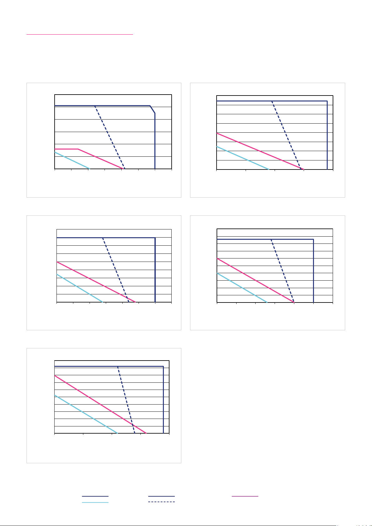
05-A85-AHCneinilnneksbeirtnA nov gnunhcereB
1200
CHA-58A-50
001-A85-AHCneinilnneksbeirtnA nov gnunhcereB
CHA-58A-100
061-A85-AHCneinilnneksbeirtnA nov gnunhcereB
2000
Drehmoment [Nm] /
CHA-58A-160
08-A85-AHCneinilnneksbeirtnA nov gnunhcereB
Drehmoment [Nm] / Torque [Nm]
CHA-58A-80
021-A85-AHCneinilnneksbeirtnA nov gnunhcereB
2000
Drehmoment [Nm] /
CHA-58A-120
6.11.4 Performance Characteristics
The performance curves shown below are valid for the specified ambient operating temperature if the motor terminal
voltage is higher or equal to the values given in the ratings table.
Illustration 37.1 Illustration 37.2
1000
800
600
400
200
0
0 10 20 30 40 50 60 70
Speed [rpm]
Illustration 37.3 Illustration 37.4
800
Torque [Nm] Torque [Nm]Torque [Nm]
600
400
200
0
0 5 10 15 20 25 30 35
Drehzahl [min-1] / Speed [rpm]
Speed [rpm]
CHA-58A-50 CHA-58A-80
1600
1400
1200
1000
800
600
400
200
0
0 10 20 30 40
CHA-58A-100 CHA-58A-120
1800
1600
1400
1200
Torque [Nm]
1000
800
Torque [Nm] Torque [Nm]
600
400
200
0
0 5 10 15 20 25 30
Drehzahl [min-1] / Speed [rpm]
Speed [rpm]
Speed [rpm]
Illustration 37.5
Legend
Intermittent duty UM = 430 VAC S3-ED 50 % (1 min)
Continuous duty UM = 220 VAC
1800
1600
1400
1200
Torque [Nm]
1000
800
600
400
200
0
0 5 10 15 20
Drehzahl [min-1] / Speed [rpm]
Speed [rpm]
CHA-58A-160
371018854 8/2018 V03
Page 38

6.12 Actuator Data CHA-20A-M512P
6.12.1 Technical Data
Table 38.1
Symbol
[Unit]
CHA-20A
Motor feedback system M512P
Ratio i [ ] 30 50 80 100 120 160
Maximum output torque T
Maximum output speed n
Maximum current I
Continuous stall torque T
Continuous stall current I
Maximum DC bus voltage U
Electrical time constant (20 °C) t
Mechanical time constant (20 °C) t
No load current I
No load running current constant (30 °C) K
No load running current constant (80 °C) K
Torque constant (at output) k
Torque constant (at motor) k
AC voltage constant (L-L, 20 °C, at motor) k
Motor terminal voltage (fundamental wave only) U
Demagnetisation current I
Maximum motor speed n
Rated motor speed n
Resistance (L-L, 20 °C) R
Inductance (L-L) L
[Nm] 27 56 74 82 87 92
max
[rpm] 200 120 75 60 50 38
max
[A
] 2.9 3.8 3.1 2.8 2.5 2.1
max
rms
[Nm] 19 32 47 49 49 49
0
[A
] 2.1 2.1 1.9 1.6 1.4 1.0
0
rms
[VDC] 680
DCmax
[ms] 1.4
e
[ms] 6.7
m
[A
] 0.19 0.17 0.14 0.14 0.13 0.13
NLS
rms
INL
INL
[V
EM
[·10-3 A
[·10-3 A
Tout
/rpm] 2 4 7 8 9 12
rms
/rpm] 0.7 2 2 3 4 5
rms
[Nm/A
[Nm/A
TM
rms
E
max
N
L- L
] 9.9 16.5 26.8 33.4 4 0.1 53.5
rms
] 0.36
rms
/1000 rpm] 23
[V
] 220 … 430
M
rms
[A
] 7.0
rms
[rpm] 6000
[rpm] 3500
[Ω] 5.9
L- L
[mH] 8.0
Number of pole pairs p [ ] 5
Weight without brake m [kg] 4.2
Weight with brake m [kg] 4.9
Hollow shaft diameter d
[mm] 18
H
6.12.2 Moment of Inertia
Table 38.2
Symbol
[Unit]
CHA-20A
Motor feedback system M512P
Ratio i [ ] 30 50 80 100 120 160
Moment of Inertia output side
Moment of inertia without brake J
Moment of inertia with brake J
[kgm²] 0.21 0.58 1.48 2.32 3.30 5.90
out
[kgm²] 0.23 0.65 1.65 2.60 3.70 6.60
out
Moment of Inertia at motor
Moment of inertia at motor without brake J [·10
Moment of inertia at motor with brake J [·10
-4
kgm²] 2.32
-4
kgm²] 2.60
6.12.3 Technical Data Brake
Table 38.3
Symbol
[Unit]
Ratio i [ ] 30 50 80 100 120 160
Brake voltage U
Brake holding torque (at output) T
Brake current to open I
Brake current to hold I
[VDC] 24 ±10 %
Br
[Nm] 27 45 72 82 87 92
Br
[ADC] 0.6
OBr
[ADC] 0.3
HBr
Number of brake cyles at n = 0 rpm 10000000
Emergency brake cyles 200
Opening time t
Closing time t
[ms] 110
O
[ms] 70
C
38 1018854 8/2018 V03
CHA-20A
Page 39
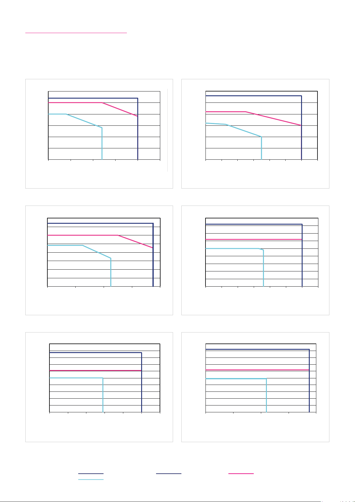
30
CHA-20A-30
80
CHA-20A-80
100
60
Drehmoment [Nm] / Torque [Nm]
CHA-20A-120
60
CHA-20A-50
90
CHA-20A-100
100
40
Drehmoment [Nm] /
CHA-20A-160
6.12.4 Performance Characteristics
The performance curves shown below are valid for the specified ambient operating temperature if the motor terminal
voltage is higher or equal to the values given in the ratings table.
Illustration 39.1 Illustration 39.2
25
20
15
10
5
0
0 50 100 150 200 250
Speed [rpm]
Illustration 39.3 Illustration 39.4
70
60
50
40
30
Torque [Nm] Torque [Nm]Torque [Nm]
20
10
0
0 20 40 60 80
CHA-20A-30 CHA-20A-50
50
40
30
20
Torque [Nm]
10
0
0 20 40 60 80 100 120 140
CHA-20A-80 CHA-20A-100
80
70
60
50
40
30
Torque [Nm]Torque [Nm]
20
10
0
0 10 20 30 40 50 60 70
Speed [rpm]
Speed [rpm]
Illustration 39.5 Illustration 39.6
90
80
70
60
50
40
30
20
10
0
0 10 20 30 40 50
Speed [rpm]
CHA-20A-120 CHA-20A-160
90
80
70
60
Torque [Nm]
50
40
30
20
10
0
0 10 20 30
Legend
Intermittent duty UM = 220 ... 430 VAC S3-ED 50 % (1 min)
Continuous duty
Speed [rpm]
Speed [rpm]
391018854 8/2018 V03
Page 40

6.13 Actuator Data CHA-25A-M512P
6.13.1 Technical Data
Table 40.1
Symbol
[Unit]
CHA-25A
Motor feedback system M512P
Ratio i [ ] 30 50 80 100 120 160
Maximum output torque T
Maximum output speed n
Maximum current I
Continuous stall torque T
Continuous stall current I
Maximum DC bus voltage U
Electrical time constant (20 °C) t
Mechanical time constant (20 °C) t
No load current I
No load running current constant (30 °C) K
No load running current constant (80 °C) K
Torque constant (at output) k
Torque constant (at motor) k
AC voltage constant (L-L, 20 °C, at motor) k
Motor terminal voltage (fundamental wave only) U
Demagnetisation current I
Maximum motor speed n
Rated motor speed n
Resistance (L-L, 20 °C) R
Inductance (L-L) L
[Nm] 50 98 137 157 167 176
max
[rpm] 187 112 70 56 47 35
max
[A
] 3.5 4.0 3.4 3.2 2.8 2.2
max
rms
[Nm] 38 55 87 108 108 108
0
[A
] 2.7 2.3 2.2 2.2 1.9 1.4
0
rms
[VDC] 680
DCmax
[ms] 1.6
e
[ms] 5.9
m
[A
] 0.21 0.19 0.15 0.1 5 0.15 0.1 4
NLS
rms
INL
INL
[V
EM
[·10-3 A
[·10-3 A
Tout
/rpm] 4 6 10 12 14 19
rms
/rpm] 1 2 3 4 5 7
rms
[Nm/A
[Nm/A
TM
rms
E
max
N
L- L
] 15.5 26.0 42.5 53.1 63.9 85.0
rms
] 0.55
rms
/1000 rpm] 37
[V
] 220 … 430
M
rms
[A
] 15
rms
[rpm] 5600
[rpm] 3500
[Ω] 3.7
L- L
[mH] 6.0
Number of pole pairs p [ ] 6
Weight without brake m [kg] 4.9
Weight with brake m [kg] 6.1
Hollow shaft diameter d
[mm] 27
H
6.13.2 Moment of Inertia
Table 40.2
Symbol
[Unit]
CHA-25A
Motor feedback system M512P
Ratio i [ ] 30 50 80 100 120 160
Moment of Inertia output side
Moment of inertia without brake J
Moment of inertia with brake J
[kgm²] 0.39 0.97 2.8 4.4 6.3 11.2
out
[kgm²] 0.46 1.27 3.2 5.1 7. 3 13.0
out
Moment of Inertia at motor
-4
Moment of inertia at motor without brake J [·10
Moment of inertia at motor with brake J [·10
kgm²] 4.4
-4
kgm²] 5.1
6.13.3 Technical Data Brake
Table 40.3
Symbol
[Unit]
Ratio i [ ] 30 50 80 100 120 160
Brake voltage U
Brake holding torque (at output) T
Brake current to open I
Brake current to hold I
[VDC] 24 ±10 %
Br
[Nm] 54 90 137 157 167 176
Br
[ADC] 0.9
OBr
[ADC] 0.4
HBr
Number of brake cyles at n = 0 rpm 10000000
Emergency brake cyles 200
Opening time t
Closing time t
[ms] 110
O
[ms] 70
C
40 1018854 8/2018 V03
CHA-25A
Page 41
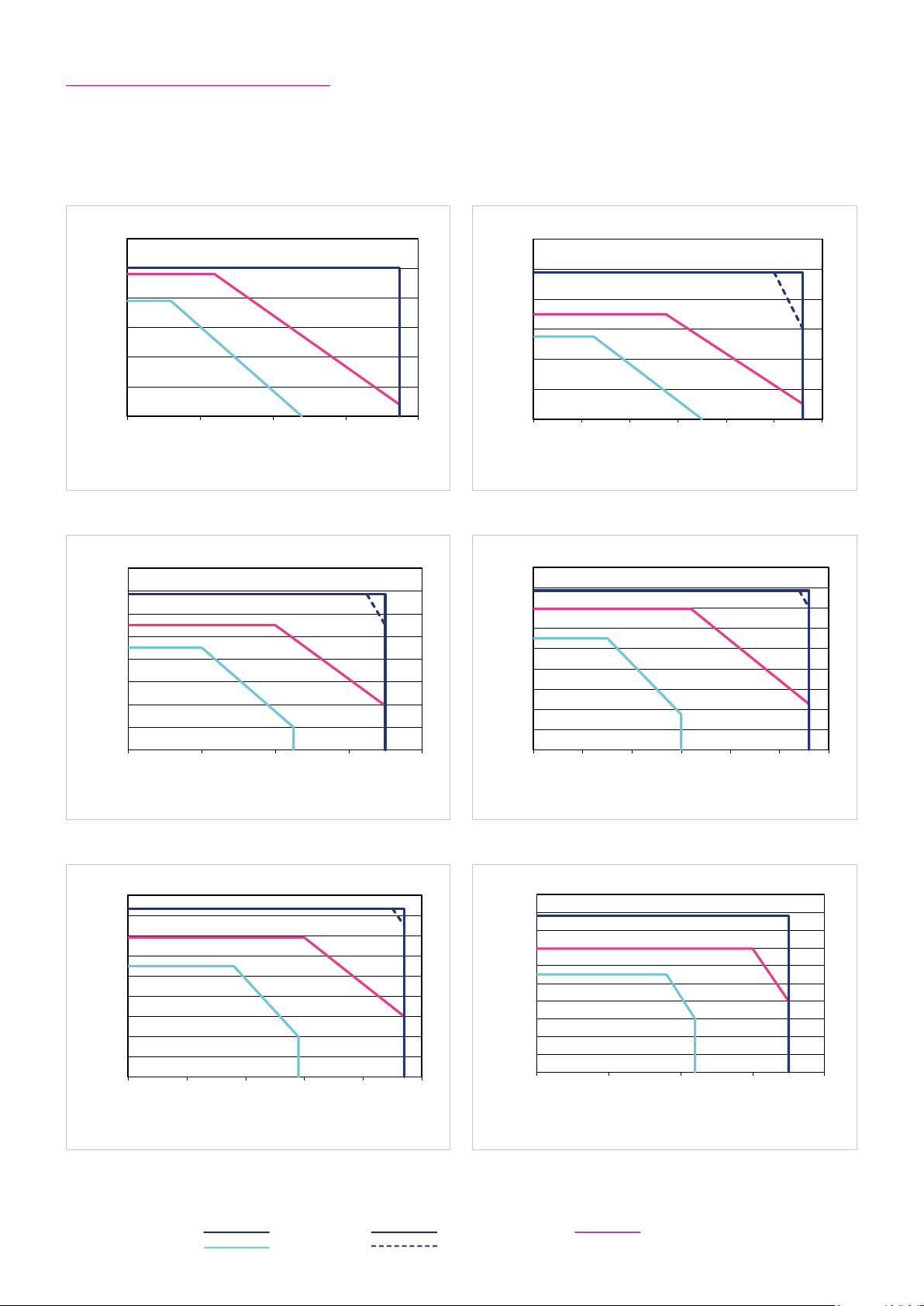
60
CHA-25A-30
08-A52-AHCneinilnneksbeirtnA nov gnunhcereB
160
80
CHA-25A-80
021-A52-AHCneinilnneksbeirtnA nov gnunhcereB
180
CHA-25A-120
05-A52-AHCneinilnneksbeirtnA nov gnunhcereB
120
CHA-25A-50
001-A52-AHCneinilnneksbeirtnA nov gnunhcereB
180
CHA-25A-100
200
CHA-25A-160
6.13.4 Performance Characteristics
The performance curves shown below are valid for the specified ambient operating temperature if the motor terminal
voltage is higher or equal to the values given in the ratings table.
Illustration 41.1 Illustration 41.2
50
40
30
20
10
0
0 50 100 150 200
Speed [rpm]
Illustration 41.3 Illustration 41.4
140
120
100
80
60
Torque [Nm] Torque [Nm]Torque [Nm]
40
20
0
0 20 40 60
Speed [rpm]
CHA-25A-30 CHA-25A-50
100
80
60
Torque [Nm]
40
20
0
0 20 40 60 80 100 120
CHA-25A-80 CHA-25A-100
160
140
120
100
80
Torque [Nm]
60
40
20
0
0 10 20 30 40 50 60
Speed [rpm]
Speed [rpm]
Illustration 41.5 Illustration 41.6
160
140
120
100
80
60
40
20
0
0 10 20 30 40 50
Speed [rpm]
Legend
Intermittent duty UM = 430 VAC S3-ED 50 % (1 min)
Continuous duty UM = 220 VAC
CHA-25A-120 CHA-25A-160
180
160
140
120
100
80
Torque [Nm]
60
40
20
0
0 10 20 30 40
Speed [rpm]
411018854 8/2018 V03
Page 42

6.14 Actuator Data CHA-32A-M512P
6.14.1 Technical Data
Table 42.1
Symbol
[Unit]
CHA-32A
Motor feedback system M512P
Ratio i [ ] 30 50 80 100 120 160
Maximum output torque T
Maximum output speed n
Maximum current I
Continuous stall torque T
Continuous stall current I
Maximum DC bus voltage U
Electrical time constant (20 °C) t
Mechanical time constant (20 °C) t
No load current I
No load running current constant (30 °C) K
No load running current constant (80 °C) K
Torque constant (at output) k
Torque constant (at motor) k
AC voltage constant (L-L, 20 °C, at motor) k
Motor terminal voltage (fundamental wave only) U
Demagnetisation current I
Maximum motor speed n
Rated motor speed n
Resistance (L-L, 20 °C) R
Inductance (L-L) L
[Nm] 100 216 304 333 353 372
max
[rpm] 160 96 60 48 40 30
max
[A
] 7.1 9.8 8.3 7. 2 6.3 5.3
max
rms
[Nm] 44 71 119 154 179 216
0
[A
] 3.2 3.2 3.2 3.2 3.2 2.9
0
rms
[VDC] 680
DCmax
[ms] 1.6
e
[ms] 7.1
m
[A
] 0.30 0.30 0.20 0.20 0.20 0.18
NLS
rms
INL
INL
[V
EM
[·10-3 A
[·10-3 A
Tout
/rpm] 6 10 17 21 25 34
rms
/rpm] 2 3 6 7 8 11
rms
[Nm/A
[Nm/A
TM
rms
E
max
N
L- L
] 15.5 25.9 42.1 52.5 63.0 84.5
rms
] 0.55
rms
/1000 rpm] 37
[V
] 220 … 430
M
rms
[A
] 15
rms
[rpm] 4800
[rpm] 3500
[Ω] 3.7
L- L
[mH] 6.0
Number of pole pairs p [ ] 6
Weight without brake m [kg] 7.6
Weight with brake m [kg] 8.8
Hollow shaft diameter d
[mm] 32
H
6.14.2 Moment of Inertia
Table 42.2
Symbol
[Unit]
CHA-32A
Motor feedback system M512P
Ratio i [ ] 30 50 80 100 120 160
Moment of Inertia output side
Moment of inertia without brake J
Moment of inertia with brake J
[kgm²] 0.55 1.50 3.9 6.1 8.7 15.6
out
[kgm²] 0.64 1.77 4.5 7.1 10.2 18.2
out
Moment of Inertia at motor
-4
Moment of inertia at motor without brake J [·10
Moment of inertia at motor with brake J [·10
kgm²] 6.1
-4
kgm²] 7.1
6.14.3 Technical Data Brake
Table 42.3
Symbol
[Unit]
Ratio i [ ] 30 50 80 100 120 160
Brake voltage U
Brake holding torque (at output) T
Brake current to open I
Brake current to hold I
[VDC] 24 ±10 %
Br
[Nm] 54 90 144 180 216 288
Br
[ADC] 0.9
OBr
[ADC] 0.4
HBr
Number of brake cyles at n = 0 rpm 10000000
Emergency brake cyles 200
Opening time t
Closing time t
[ms] 110
O
[ms] 70
C
42 1018854 8/2018 V03
CHA-32A
Page 43
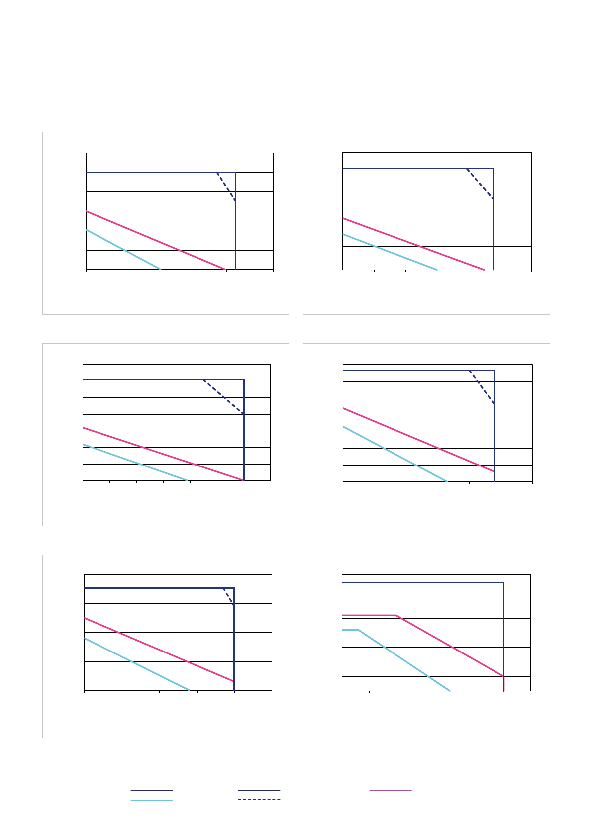
03-A23-AHCneinilnneksbeirtnA nov gnunhcereB
120
CHA-32A-30
08-A23-AHCneinilnneksbeirtnA nov gnunhcereB
350
Drehmoment [Nm] / Torque [Nm]
CHA-32A-80
021-A23-AHCneinilnneksbeirtnA nov gnunhcereB
400
CHA-32A-120
05-A23-AHCneinilnneksbeirtnA nov gnunhcereB
CHA-32A-50
001-A23-AHCneinilnneksbeirtnA nov gnunhcereB
350
CHA-32A-100
061-A23-AHCneinilnneksbeirtnA nov gnunhcereB
400
CHA-32A-160
6.14.4 Performance Characteristics
The performance curves shown below are valid for the specified ambient operating temperature if the motor terminal
voltage is higher or equal to the values given in the ratings table.
Illustration 43.1 Illustration 43.2
100
80
60
Torque [Nm]
40
20
0
0 50 100 150 200
Speed [rpm]
Illustration 43.3 Illustration 43.4
300
250
200
150
Torque [Nm]
100
50
0
0 10 20 30 40 50 60 70
Drehzahl [min-1] / Speed [rpm]
Speed [rpm]
CHA-32A-30 CHA-32A-50
250
200
150
100
Torque [Nm]
50
0
0 20 40 60 80 100 120
CHA-32A-80 CHA-32A-100
300
250
200
150
Torque [Nm]Torque [Nm]
100
50
0
0 10 20 30 40 50 60
Speed [rpm]
Speed [rpm]
Illustration 43.5 Illustration 43.6
350
300
250
200
150
Torque [Nm]
100
50
Legend
Intermittent duty UM = 430 VAC S3-ED 50 % (1 min)
Continuous duty UM = 220 VAC
0
0 10 20 30 40 50
Speed [rpm]
CHA-32A-120 CHA-32A-160
350
300
250
200
150
100
50
0
0 5 10 15 20 25 30 35
Speed [rpm]
431018854 8/2018 V03
Page 44

6.15 Actuator Data CHA-40A-M512P
6.15.1 Technical Data
Table 44.1
Symbol
[Unit]
CHA-40A
Motor feedback system M512P
Ratio i [ ] 50 80 100 120 160
Maximum output torque T
Maximum output speed n
Maximum current I
Continuous stall torque T
Continuous stall current I
Maximum DC bus voltage U
Electrical time constant (20 °C) t
Mechanical time constant (20 °C) t
No load current I
No load running current constant (30 °C) K
No load running current constant (80 °C) K
Torque constant (at output) k
Torque constant (at motor) k
AC voltage constant (L-L, 20 °C, at motor) k
Motor terminal voltage (fundamental wave only) U
Demagnetisation current I
Maximum motor speed n
Rated motor speed n
Resistance (L-L, 20 °C) R
Inductance (L-L) L
[Nm] 402 519 568 617 647
max
[rpm] 80 50 40 33 25
max
[A
] 11.8 9.2 8.1 7. 3 5.9
max
rms
[Nm] 125 208 260 314 420
0
[A
] 3.6 3.6 3.6 3.6 3.6
0
rms
[VDC] 680
DCmax
[ms] 2.1
e
[ms] 6.8
m
[A
] 0.30 0.20 0.20 0.20 0.20
NLS
rms
INL
INL
[V
EM
[·10-3 A
[·10-3 A
Tout
/rpm] 13 20 25 30 40
rms
/rpm] 4 6 8 10 13
rms
[Nm/A
[Nm/A
TM
rms
E
max
N
L- L
] 38 62 77 92 123
rms
] 0.83
rms
/1000 rpm] 53
[V
] 220 … 430
M
rms
[A
] 18
rms
[rpm] 4000
[rpm] 3000
[Ω] 2.9
L- L
[mH] 6.0
Number of pole pairs p [ ] 6
Weight without brake m [kg] 12.7
Weight with brake m [kg] 14.8
Hollow shaft diameter d
[mm] 39
H
6.15.2 Moment of Inertia
Table 44.2
Symbol
[Unit]
CHA-40A
Motor feedback system M512P
Ratio i [ ] 50 80 100 120 160
Moment of Inertia output side
Moment of inertia without brake J
Moment of inertia with brake J
[kgm²] 3.40 8.60 13.5 19.4 34.6
out
[kgm²] 3.90 9.80 15.4 22.2 39.4
out
Moment of Inertia at motor
-4
Moment of inertia at motor without brake J [·10
Moment of inertia at motor with brake J [·10
kgm²] 13.5
-4
kgm²] 15.4
6.15.3 Technical Data Brake
Table 44.3
Symbol
[Unit]
Ratio i [ ] 50 80 100 120 160
Brake voltage U
Brake holding torque (at output) T
Brake current to open I
Brake current to hold I
[VDC] 24 ±10 %
Br
[Nm] 225 360 450 540 647
Br
[ADC] 0.7
OBr
[ADC] 0.3
HBr
Number of brake cyles at n = 0 rpm 10000000
Emergency brake cyles 200
Opening time t
Closing time t
[ms] 110
O
[ms] 70
C
44 1018854 8/2018 V03
CHA-40A
Page 45

05-A04-AHCneinilnneksbeirtnA nov gnunhcereB
Drehmoment [Nm] / Torque [Nm]
CHA-40A-50
001-A04-AHCneinilnneksbeirtnA nov gnunhcereB
600
CHA-40A-100
061-A04-AHCneinilnneksbeirtnA nov gnunhcereB
700
CHA-40A-160
08-A04-AHCneinilnneksbeirtnA nov gnunhcereB
600
Drehmoment [Nm] / Torque [Nm]
CHA-40A-80
021-A04-AHCneinilnneksbeirtnA nov gnunhcereB
700
Drehmoment [Nm] / Torque [Nm]
CHA-40A-120
6.15.4 Performance Characteristics
The performance curves shown below are valid for the specified ambient operating temperature if the motor terminal
voltage is higher or equal to the values given in the ratings table.
Illustration 45.1 Illustration 45.2
450
400
350
300
250
200
150
100
50
0
0 20 40 60 80 100
Speed [rpm]
Illustration 45.3 Illustration 45.4
500
400
300
Torque [Nm] Torque [Nm]Torque [Nm]
200
100
0
0 10 20 30 40 50
Speed [rpm]
CHA-40A-50 CHA-40A-80
500
400
300
200
100
0
0 10 20 30 40 50 60
CHA-40A-100 CHA-40A-120
600
500
400
300
Torque [Nm] Torque [Nm]
200
100
0
0 5 10 15 20 25 30 35
Speed [rpm]
Speed [rpm]
Illustration 45.5
600
500
400
300
200
100
0
0 5 10 15 20 25 30
Speed [rpm]
Legend
Intermittent duty UM = 430 VAC S3-ED 50 % (1 min)
Continuous duty UM = 220 VAC
CHA-40A-160
451018854 8/2018 V03
Page 46

6.16 Actuator Data CHA-50A-M512P
6.16.1 Technical Data
Table 46.1
Symbol
[Unit]
CHA-50A
Motor feedback system M512P
Ratio i [ ] 50 80 100 120 160
Maximum output torque T
Maximum output speed n
Maximum current I
Continuous stall torque T
Continuous stall current I
Maximum DC bus voltage U
Electrical time constant (20 °C) t
Mechanical time constant (20 °C) t
No load current I
No load running current constant (30 °C) K
No load running current constant (80 °C) K
Torque constant (at output) k
Torque constant (at motor) k
AC voltage constant (L-L, 20 °C, at motor) k
Motor terminal voltage (fundamental wave only) U
Demagnetisation current I
Maximum motor speed n
Rated motor speed n
Resistance (L-L, 20 °C) R
Inductance (L-L) L
[Nm] 715 941 980 1080 1180
max
[rpm] 70 44 35 30 22
max
[A
] 10.2 8.3 6.9 6.4 5.3
max
rms
[Nm] 194 363 456 550 736
0
[A
] 2.9 3.2 3.2 3.2 3.1
0
rms
[VDC] 680
DCmax
[ms] 3.4
e
[ms] 4.7
m
[A
] 0.30 0.20 0.20 0.17 0.1 6
NLS
rms
INL
INL
[V
EM
[·10-3 A
[·10-3 A
Tout
/rpm] 12 20 25 29 39
rms
/rpm] 4 6 8 9 12
rms
[Nm/A
[Nm/A
TM
rms
E
max
N
L- L
] 74 121 145 181 242
rms
] 1.60
rms
/1000 rpm] 104
[V
] 220 … 430
M
rms
[A
] 18
rms
[rpm] 3500
[rpm] 2500
[Ω] 3.5
L- L
[mH] 12
Number of pole pairs p [ ] 6
Weight without brake m [kg] 20.9
Weight with brake m [kg] 24.5
Hollow shaft diameter d
[mm] 45
H
6.16.2 Moment of Inertia
Table 46.2
Symbol
[Unit]
CHA-50A
Motor feedback system M512P
Ratio i [ ] 50 80 100 120 160
Moment of Inertia output side
Moment of inertia without brake J
Moment of inertia with brake J
[kgm²] 6.90 1 7.7 2 7.7 39.9 71.0
out
[kgm²] 7.90 19.5 3 0.4 43.8 77.8
out
Moment of Inertia at motor
-4
Moment of inertia at motor without brake J [·10
Moment of inertia at motor with brake J [·10
kgm²] 27.7
-4
kgm²] 30.4
6.16.3 Technical Data Brake
Table 46.3
Symbol
[Unit]
Ratio i [ ] 50 80 100 120 160
Brake voltage U
Brake holding torque (at output) T
Brake current to open I
Brake current to hold I
[VDC] 24 ±10 %
Br
[Nm] 225 360 450 540 720
Br
[ADC] 0.7
OBr
[ADC] 0.3
HBr
Number of brake cyles at n = 0 rpm 10000000
Emergency brake cyles 200
Opening time t
Closing time t
[ms] 110
O
[ms] 70
C
46 1018854 8/2018 V03
CHA-50A
Page 47

05-A05-AHCneinilnneksbeirtnA nov gnunhcereB
800
Drehmoment [Nm] / Torque [Nm]
CHA-50A-50
001-A05-AHCneinilnneksbeirtnA nov gnunhcereB
1200
CHA-50A-100
061-A05-AHCneinilnneksbeirtnA nov gnunhcereB
1400
25
Drehmoment [Nm] / Torque [Nm]
CHA-50A-160
08-A05-AHCneinilnneksbeirtnA nov gnunhcereB
Drehmoment [Nm] / Torque [Nm]
CHA-50A-80
021-A05-AHCneinilnneksbeirtnA nov gnunhcereB
1200
CHA-50A-120
6.16.4 Performance Characteristics
The performance curves shown below are valid for the specified ambient operating temperature if the motor terminal
voltage is higher or equal to the values given in the ratings table.
Illustration 47.1 Illustration 47.2
700
600
500
400
300
Torque [Nm]
200
100
0
0 20 40 60 80
Drehzahl [min-1] / Speed [rpm]
Illustration 47.3 Illustration 47.4
1000
800
Speed [rpm]
CHA-50A-50 CHA-50A-80
1000
900
800
700
600
500
400
300
200
100
0
0 10 20 30 40 50
CHA-50A-100 CHA-50A-120
1000
800
Drehzahl [min-1] / Speed [rpm]
Speed [rpm]
Torque [Nm]
Illustration 47.5
Torque [Nm]
600
400
200
0
0 10 20 30 40
Drehzahl [min-1] / Speed [rpm]
Speed [rpm]
CHA-50A-160
1200
1000
800
600
400
200
0
0 5 10 15 20
Speed [rpm]
600
Torque [Nm] Torque [Nm]
400
200
0
0 5 10 15 20 25 30 35
Drehzahl [min-1] / Speed [rpm]
Speed [rpm]
Legend
Intermittent duty UM = 430 VAC S3-ED 50 % (1 min)
Continuous duty UM = 220 VAC
471018854 8/2018 V03
Page 48
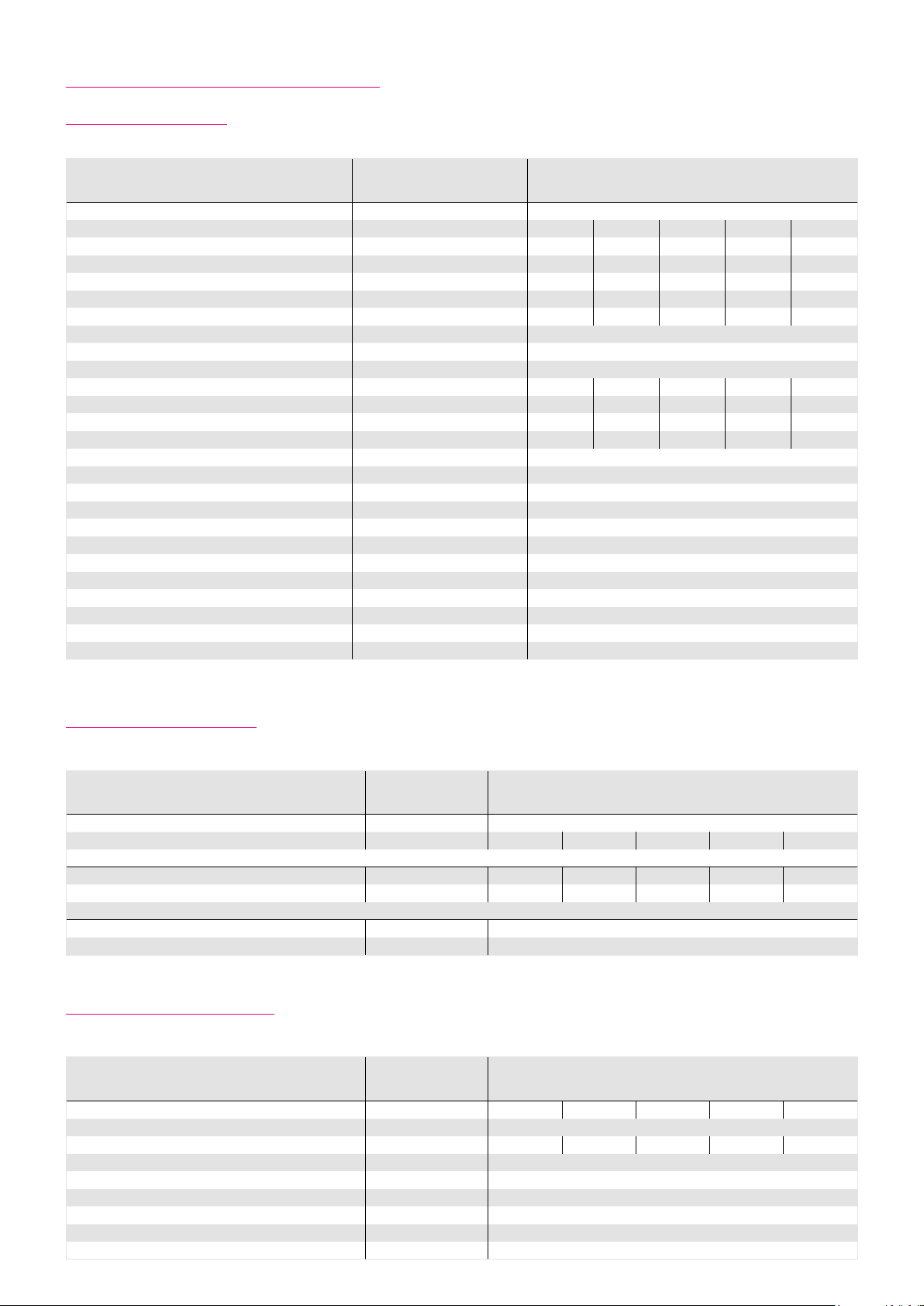
6.17 Actuator Data CHA-58A-M512P
6.17.1 Technical Data
Table 48.1
Symbol
[Unit]
CHA-58A
Motor feedback system M512P
Ratio i [ ] 50 80 100 120 160
Maximum output torque T
Maximum output speed n
Maximum current I
Continuous stall torque T
Continuous stall current I
Maximum DC bus voltage U
Electrical time constant (20 °C) t
Mechanical time constant (20 °C) t
No load current I
No load running current constant (30 °C) K
No load running current constant (80 °C) K
Torque constant (at output) k
Torque constant (at motor) k
AC voltage constant (L-L, 20 °C, at motor) k
Motor terminal voltage (fundamental wave only) U
Demagnetisation current I
Maximum motor speed n
Rated motor speed n
Resistance (L-L, 20 °C) R
Inductance (L-L) L
[Nm] 1020 1480 1590 1720 1840
max
[rpm] 60 38 30 25 19
max
[A
] 1 4.4 12.8 11.1 10.0 8.1
max
rms
[Nm] 280 532 670 805 1080
0
[A
] 4.2 4.6 4.6 4.6 4.6
0
rms
[VDC] 680
DCmax
[ms] 3.5
e
[ms] 5 .4
m
[A
] 0.40 0.28 0.26 0.25 0.23
NLS
rms
INL
INL
[V
EM
[·10-3 A
[·10-3 A
Tout
/rpm] 19 30 38 46 61
rms
/rpm] 6 10 12 15 19
rms
[Nm/A
[Nm/A
TM
rms
E
max
N
L- L
] 75 122 152 183 244
rms
] 1.70
rms
/1000 rpm] 105
[V
] 220 … 430
M
rms
[A
] 25
rms
[rpm] 3000
[rpm] 2000
[Ω] 2.4
L- L
[mH] 9
Number of pole pairs p [ ] 6
Weight without brake m [kg] 28.2
Weight with brake m [kg] 32.0
Hollow shaft diameter d
[mm] 45
H
6.17.2 Moment of Inertia
Table 48.2
Symbol
[Unit]
CHA-58A
Motor feedback system M512P
Ratio i [ ] 50 80 100 120 160
Moment of Inertia output side
Moment of inertia without brake J
Moment of inertia with brake J
[kgm²] 11.9 30.6 4 7.8 68.8 122
out
[kgm²] 12.1 31.1 48.5 69.8 124
out
Moment of Inertia at motor
-4
Moment of inertia at motor without brake J [·10
Moment of inertia at motor with brake J [·10
kgm²] 47.8
-4
kgm²] 48.5
6.17.3 Technical Data Brake
Table 48.3
Symbol
[Unit]
Ratio i [ ] 50 80 100 120 160
Brake voltage U
Brake holding torque (at output) T
Brake current to open I
Brake current to hold I
[VDC] 24 ±10 %
Br
[Nm] 450 720 900 1080 1440
Br
[ADC] 0.7
OBr
[ADC] 0.5
HBr
Number of brake cyles at n = 0 rpm 10000000
Emergency brake cyles 200
Opening time t
Closing time t
[ms] 110
O
[ms] 70
C
48 1018854 8/2018 V03
CHA-58A
Page 49
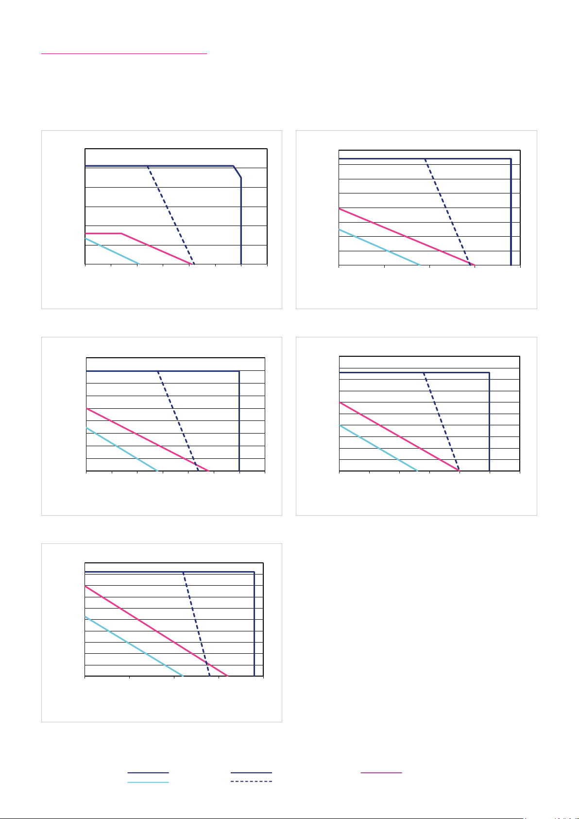
05-A85-AHCneinilnneksbeirtnA nov gnunhcereB
1200
CHA-58A-50
001-A85-AHCneinilnneksbeirtnA nov gnunhcereB
Drehmoment [Nm] / Torque [Nm]
CHA-58A-100
061-A85-AHCneinilnneksbeirtnA nov gnunhcereB
Drehmoment [Nm] /
CHA-58A-160
08-A85-AHCneinilnneksbeirtnA nov gnunhcereB
1600
Drehmoment [Nm] / Torque [Nm]
CHA-58A-80
021-A85-AHCneinilnneksbeirtnA nov gnunhcereB
2000
Drehmoment [Nm] / Torque [Nm]
CHA-58A-120
6.17.4 Performance Characteristics
The performance curves shown below are valid for the specified ambient operating temperature if the motor terminal
voltage is higher or equal to the values given in the ratings table.
Illustration 49.1 Illustration 49.2
1000
800
600
400
200
0
0 10 20 30 40 50 60 70
Speed [rpm]
Illustration 49.3 Illustration 49.4
1800
1600
1400
1200
1000
800
Torque [Nm] Torque [Nm]Torque [Nm]
600
400
200
0
0 5 10 15 20 25 30 35
Drehzahl [min-1] / Speed [rpm]
Speed [rpm]
CHA-58A-50 CHA-58A-80
1400
1200
1000
800
600
400
200
0
0 10 20 30 40
CHA-58A-100 CHA-58A-120
1800
1600
1400
1200
1000
800
Torque [Nm] Torque [Nm]
600
400
200
0
0 5 10 15 20 25 30
Speed [rpm]
Speed [rpm]
Illustration 49.5
Legend
Intermittent duty UM = 430 VAC S3-ED 50 % (1 min)
Continuous duty UM = 220 VAC
2000
1800
1600
1400
1200
Torque [Nm]
1000
800
600
400
200
0
0 5 10 15 20
Drehzahl [min-1] / Speed [rpm]
Speed [rpm]
CHA-58A-160
491018854 8/2018 V03
Page 50
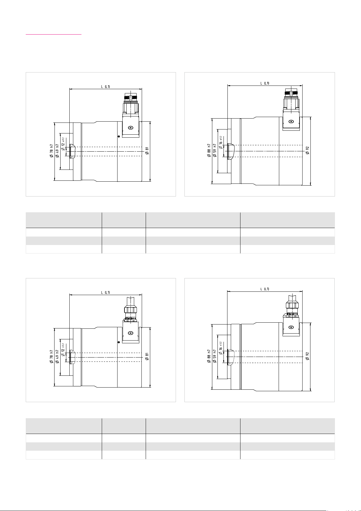
6.18 Dimensions
Illustration 50.1 Illustration 50.2[mm] [mm]
Table 50.3
Motor feedback system RES / D2048 / M128S RES / D2048 / M128S
Length (without brake) L [mm] 97.5 101
Length (with brake) L1 [mm] 120.6 123
CHA-14A-E CHA-17A-E
Symbol
[Unit]
CHA-14A-E CHA-17A-E
Illustration 50.4 Illustration 50.5[mm] [mm]
Table 50.6
Motor feedback system RES / D2048 / M128S RES / D2048 / M128S
Length (without brake) L [mm] 97.5 101
Length (with brake) L1 [mm] 120.6 123
CHA-14A CHA-17A
Symbol
[Unit]
CHA-14A CHA-17A
50 1018854 8/2018 V03
Page 51
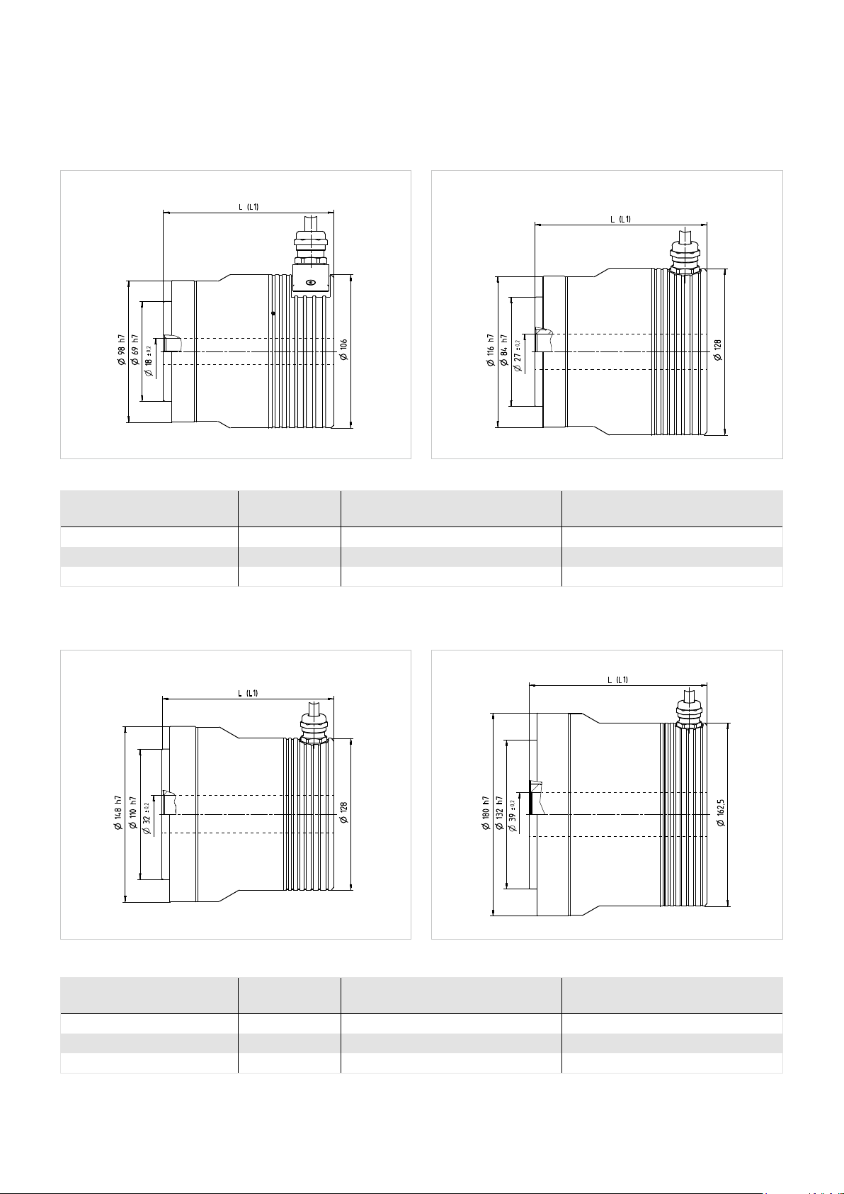
Illustration 51.1 Illustration 51.2[mm] [mm]
Table 51.3
Motor feedback system C1024 C1024
Length (without brake) L [mm] 118 132.5
Length (with brake) L1 [mm] 138 160
CHA-20A CHA-25A
Symbol
[Unit]
CHA-20A CHA-25A
Illustration 51.4 Illustration 51.5[mm] [mm]
Table 51.6
Motor feedback system C1024 C1024
Length (without brake) L [mm] 145 158
Length (with brake) L1 [mm] 172.5 177
CHA-32A CHA-40A
Symbol
[Unit]
CHA-32A CHA-40A
511018854 8/2018 V03
Page 52
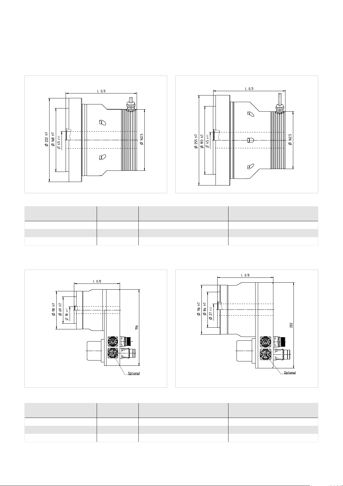
Illustration 52.1 Illustration 52.2[mm] [mm]
Table 52.3
Motor feedback system C1024 C1024
Length (without brake) L [mm] 189 205
Length (with brake) L1 [mm] 208 226
CHA-50A CHA-58A
Symbol
[Unit]
CHA-50A CHA-58A
Illustration 52.4 Illustration 52.5[mm] [mm]
Table 52.6
Motor feedback system M512P M512P
Length (without brake) L [mm] 118 132
Length (with brake) L1 [mm] 137 159.5
CHA-20A-M512P CHA-25A-M512P
Symbol
[Unit]
CHA-20A CHA-25A
52 1018854 8/2018 V03
Page 53

Illustration 53.1 Illustration 53.2[mm] [mm]
Table 53.3
Motor feedback system M512P M512P
Length (without brake) L [mm] 144.5 157
Length (with brake) L1 [mm] 172 176
CHA-32A-M512P CHA-40A-M512P
Symbol
[Unit]
CHA-32A CHA-40A
Illustration 53.4 Illustration 53.5[mm] [mm]
Table 53.6
Motor feedback system M512P M512P
Length (without brake) L [mm] 188.5 204.4
Length (with brake) L1 [mm] 20 7.5 225.4
CHA-50A-M512P CHA-58A-M512P
Symbol
[Unit]
CHA-50A CHA-58A
531018854 8/2018 V03
Page 54
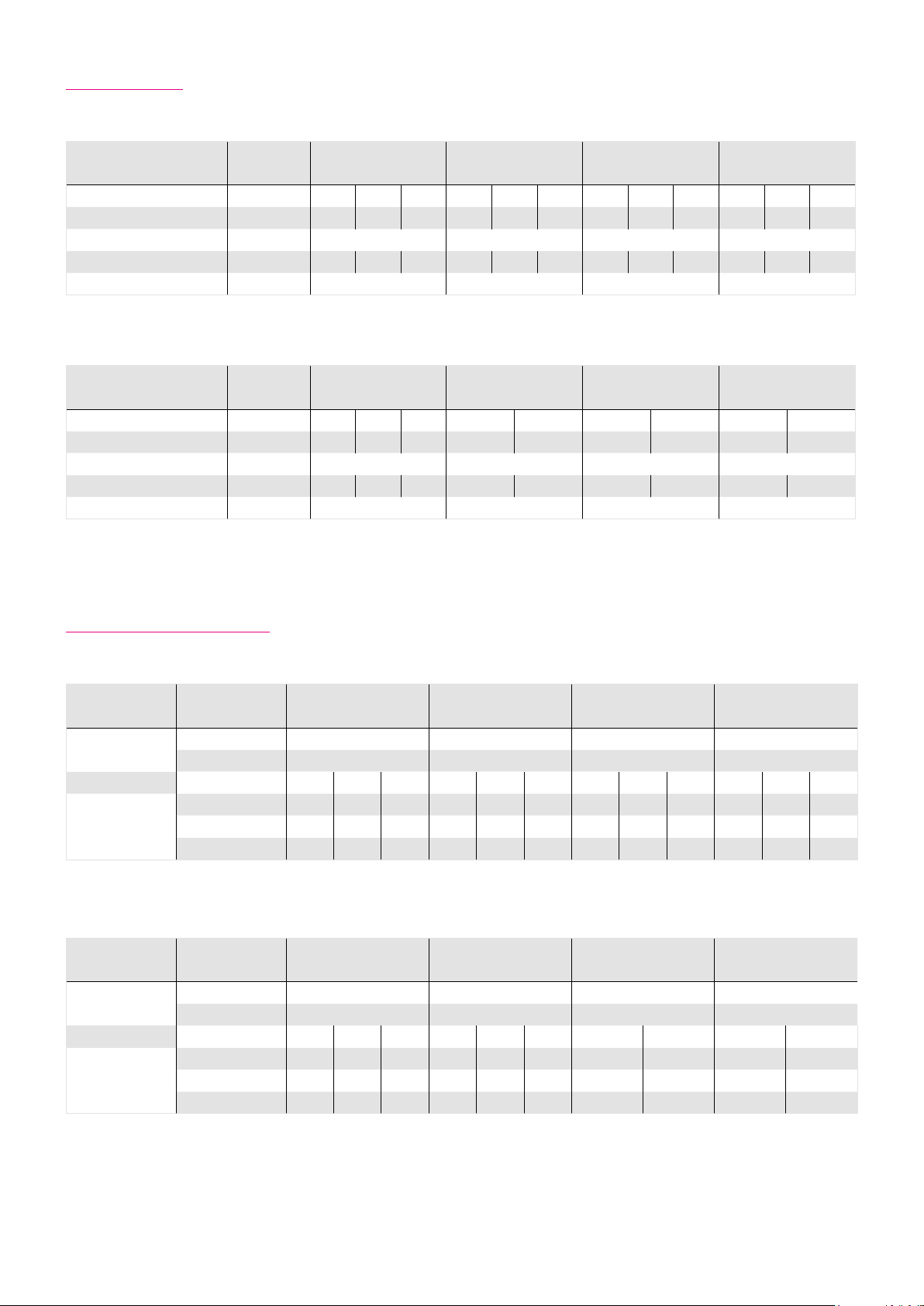
6.19 Accuracy
Table 54.1
Symbol
[Unit]
CHA-14A CHA-17A CHA-20A CHA-25A
Ratio i [ ] 30 50 > 50 30 50 > 50 30 50 > 50 30 50 > 50
Transmission accuracy [arcmin] < 2 < 1.2 < 1 < 2 < 1.2 < 1 < 1.5 < 1 < 0.8 < 1.5 < 1 < 0.8
Repeatability [arcmin] < ±0.1 < ±0.1 < ±0.1 < ±0.1
Hysteresis loss [arcmin] < 3 < 1 < 1 < 3 < 1 < 1 < 3 < 1 < 1 < 3 < 1 < 1
Lost Motion [arcmin] < 1 < 1 < 1 < 1
Table 54.2
Symbol
[Unit]
CHA-32A CHA-40A CHA-50A CHA-58A
Ratio i [ ] 30 50 > 50 50 > 50 50 > 50 50 > 50
Transmission accuracy [arcmin] < 1.5 < 1 < 0.8 < 0.7 < 0.5 < 0.7 < 0.5 < 0.7 < 0.5
Repeatability [arcmin] < ±0.1 < ±0.1 < ±0.1 < ±0.1
Hysteresis loss [arcmin] < 3 < 1 < 1 < 1 < 1 < 1 < 1 < 1 < 1
Lost Motion [arcmin] < 1 < 1 < 1 < 1
6.20 Torsional Stiness
Table 54.3
Symbol [Unit] CHA-14A CHA-17A CHA-20A CHA-25A
T
[Nm] 2 3.9 7 14
Limit torques
Ratio i [ ] 30 50 > 50 30 50 > 50 30 50 > 50 30 50 > 50
Torsional stiness
Table 54.4
Symbol [Unit] CHA-32A CHA-40A CHA-50A CHA-58A
Limit torques
Ratio i [ ] 30 50 > 50 30 50 > 50 50 > 50 50 > 50
Torsional stiness
1
[Nm] 6.9 12 25 48
T
2
K
[·103 Nm/rad] 3.4 5.7 7.1 6.7 13 16 11 23 29 21 44 57
3
[·103 Nm/rad] 2.4 4.7 6.1 4.4 11 14 7. 1 18 25 13 34 50
K
2
[·103 Nm/rad] 1.9 3.4 4.7 3.4 8.1 10 5.7 13 16 10 25 31
K
1
T
[Nm] 29 54 108 168
1
[Nm] 108 196 382 598
T
2
K
[·103 Nm/rad] 49 98 120 - 180 230 340 440 540 710
3
[·103 Nm/rad] 30 78 110 - 140 200 280 400 440 610
K
2
[·103 Nm/rad] 24 54 67 - 100 130 200 250 310 400
K
1
54 1018854 8/2018 V03
Page 55
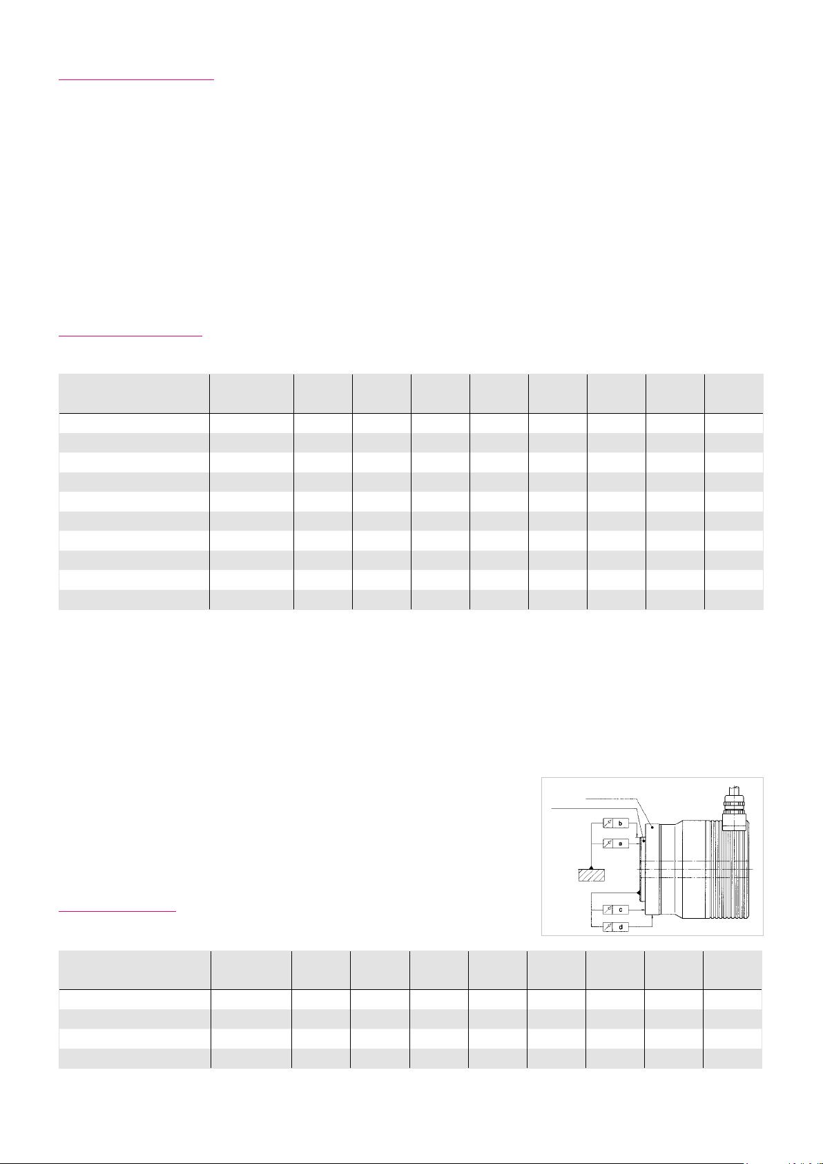
6.21 Output Bearing
CHA Series AC hollow shaft Servo Actuators incorporate a high stiness cross roller bearing to support output loads. This
specially developed bearing can withstand high axial and radial forces as well as high tilting moments. The reduction gear
is thus protected from external loads, so guaranteeing a long life and consistent performance. The integration of an output
bearing also serves to reduce subsequent design and production costs, by removing the need for an additional output bearing
in many applications. Furthermore, installation and assembly of the CHA Servo Actuators are greatly simplified.
6.21.1 Technical Data
Table 55.1
Bearing type
1)
Pitch circle diameter d
Symbol
[Unit]
[m] 0.049 0.058 0.070 0.088 0.114 0.134 0.17 1 0.192
p
CHA-14A CHA-17A CHA-20A CHA-25A CHA-32A CHA-40A CHA-50A CHA-58A
F F F C C C C C
Oset R [m] 0.014 0.014 0.016 0.018 0.020 0.026 0.028 0.029
Dynamic load rating C [N] 8500 11500 24200 30000 34500 43300 81600 87400
Stating load rating C
Dynamic tilting moment
Static tilting moment
Tilting moment stiness
Dynamic axial load
Dynamic radial load
1)
C=Cross roller bearing, F = Four point contact bearing
2)
These values are valid for moving gears. They are not based on the equation
for lifetime of the output bearing but on the maximum allowable deflection
of the Harmonic Drive® Component set. The values indicated in the table must
not be exceeded even if the lifetime equation of the bearing permits higher values.
3)
These values are valid for gears at a standstill and for a static load safety factor fs= 1,8 for size 14 ... 20
4)
These data are valid for n = 15 rpm and L10 = 15000 h
3) 4)
These data are only valid if the following conditions are fulfilled:
for M
F
F
5)
Average value
= 1,5 for size 25 ... 58.
and f
s
: Fa = 0 N; Fr = 0 N
0
: M = 0 Nm; Fr = 0 N
a
: M = 0 Nm; Fa = 0 N
r
2)
3)
5)
4)
4)
[N] 11400 17100 31000 45000 59000 81600 149000 171000
0
M
[Nm] 73 114 172 254 578 886 1558 2222
dyn (max)
M
[Nm] 155 276 603 1050 2242 3645 8493 10944
0 (max)
KB [Nm/arcmin] 23 40 70 114 350 522 1020 1550
F
[N] 2880 4600 15800 19200 22300 42000 56100 57700
A dyn (max)
F
[N] 1450 2300 8600 12700 14600 27500 37300 38400
R dyn (max)
Illustration 55.2
Gehäuse
Abtriebsflansch
6.21.2 Tolerances
Table 55.3
a [mm] 0.010 0.010 0.010 0.010 0.012 0.012 0.015 0.015
b [mm] 0.010 0.010 0.010 0.010 0.010 0.010 0.010 0.010
c [mm] 0.010 0.010 0.010 0.010 0.012 0.012 0.015 0.015
d [mm] 0.010 0.010 0.010 0.010 0.010 0.010 0.010 0.010
Unit CHA-14A CHA-17A CHA-20A CHA-25A CHA-32A CHA-40A CHA-50A CHA-58A
551018854 8/2018 V03
Page 56
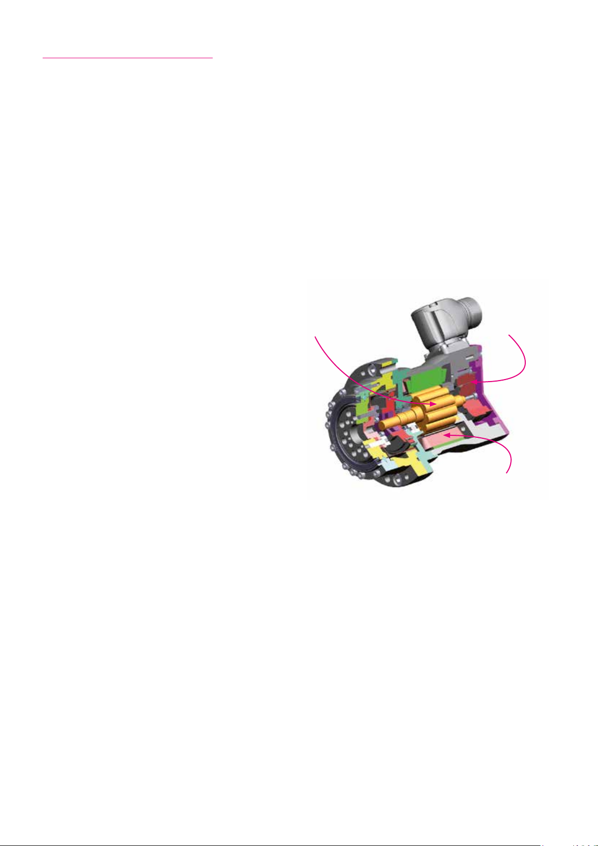
6.22 Motor Feedback Systems
Design and Operation
For accurate position setting, the servo motor and its control device are fitted with a measuring device (feedback), which
determines the current position (e.g. the angle of redation set for a starting position) of the motor.
This measurement is eected via a redary encoder, e.g. a resolver, an incremental encoder or an absolute encoder. The
position controller compares the signal from this encoder with the pre-set position value. If there is any deviation, then the
motor is turned in the direction which represents a shorter path to the set value which leads to the deviation being reduced.
The procedure repeats itself until the value lies incrementally or approximately within the tolerance limits. Alternatively, the
motor position can also be digitally recorded and compared by computer to a set value.
Servo motors and actuators from Harmonic Drive AG use various motor feedback systems which are used as position transducers to fulfil several requirements.
Commutation
Commutation signals or absolute position values provide the
necessary information about the rotor position, in order to
guarantee correct commutation.
Rotor
Motor feedback
Actual Speed
The actual speed is obtained in the servo controller using
the feedback signal, from the cyclical change in position
information.
Actual Position
Incremental encoder
The actual signal value needed for setting the position is formed by adding up the incremental position changes. Where
incremental encoders have square wave signals, definition of
the edge evaluation can be quadrupled (quad counting).
Where incremental encoders have SIN / COS signals, then the definition can be increased by interpolation in the control
device.
Absolute encoder
Absolute encoders deliver absolute position information about one (single turn) or several (multi-turn) rotations. This information can on the one hand provide the rotor position for commutation and on the other hand possibly a reference of travel.
Where absolute encoders have additional incremental signals, then typically the absolute position information can be read at
power up and the incremental signals then evaluated to determine the rotation and actual position value.
Fully digital absolute encoders as motor feedback systems have such a high definition of the absolute value that there is no
need for additional incremental signals.
Stator
Resolution
In conjunction with the Harmonic Drive AG high precision gears, the output side position can be recorded via the motor feedback system without any additional angle encoders having to be used. The resolution of the motor feedback system can also
be multiplied by gear ratio.
Output Side Angle Measurement Devices
Where applications place higher demands on accuracy or need torsion compensation at high torque load, the actual position
can also be detected by an additional sensor mounted at the gearbox output side. The adaptation of an output side
measurement sytem can be very simply realised for hollow shaft actuators.
56 1018854 8/2018 V03
Page 57

6.22.1 C1024
Incremental motor feedback with SIN / COS signals
reference and commutation signals
Table 57.1
Ordering code
Manufacturer's designation CCK
Power supply
Current consumption
1)
1)
Incremental signals u
Signal form sinusoidal
Number of pulses n
Commutation signals u
Signal form sinusoidal
Number of pulses n
Reference signal n
1)
Accuracy
Incremental resolution (motor side)
Resolution (output side)
1)
Source: Manufacturer
2)
For interpolation with 8 bit
2)
2)
Symbol
[Unit]
C1024
Ub [VDC] 5 ±10 %
I [mA] 150
] 1 +20 % ... -25 %
pp [Vss
[A / B] 1024
1
] 1
pp [Vss
[C / D] 1
2
[R] 1
3
[arcsec] ±12
inc [ ] 262144
Gear ratio
i [ ] 30 50 80 100 120 160
[arcsec] 0.16 0.10 0.06 0.05 0.04 0.03
Signal Wave Form
Illustration 57.2
360°el.=
U[V]
A
0
B
0
R
C
D
R
45°el.
0
180°el. ± 90°el.
0
0
0
360° mech.
1024
360°el.= 360°mech.
ADVICE
When using Siemens SINAMICS drive components, only the
use of SMC20 is relased.
ϕ
ϕ
ϕ
ϕ
ϕ
ϕ
Valid for direction of rotation
- CW at the motor shaft (when viewed from the front face of the motor)
- CCW at the output flange
571018854 8/2018 V03
Page 58
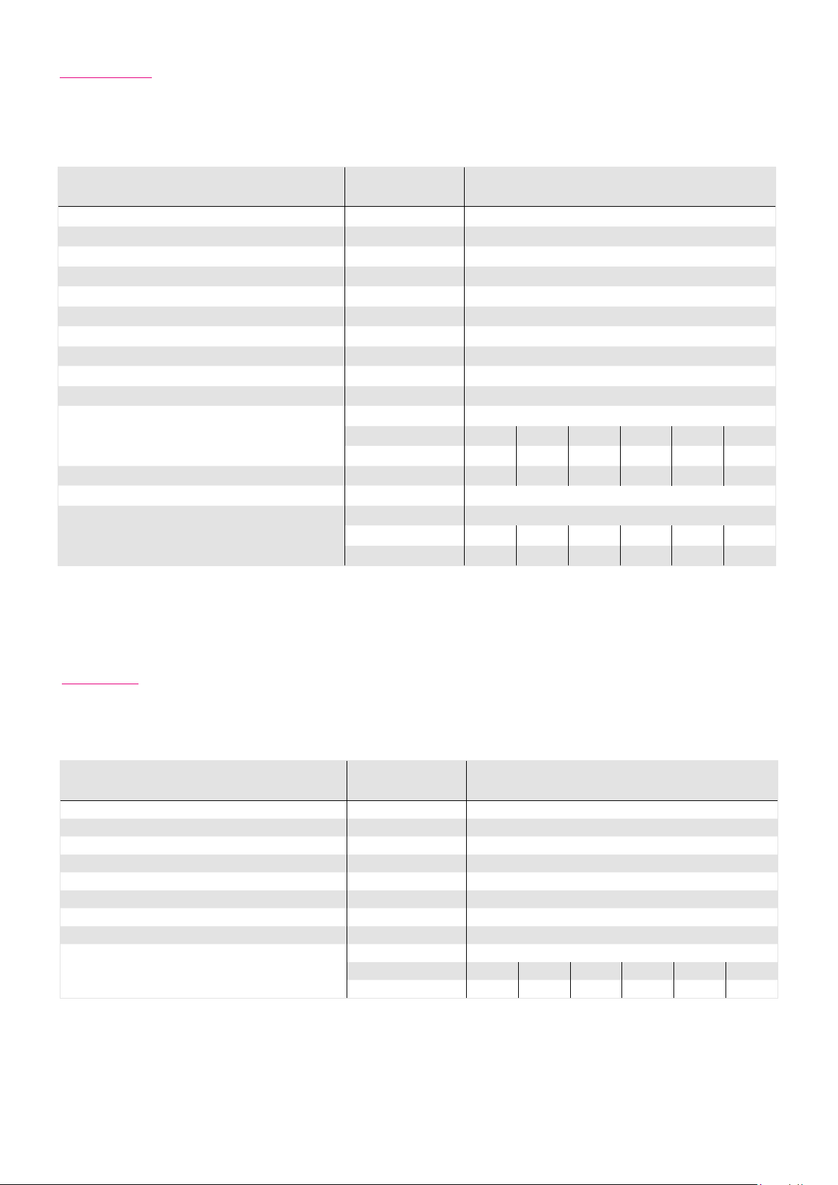
6.22.2 M512P
Multi-turn absolute motor feedback system with incremental
SIN / COS signals and EnDat® data interface
Table 58.1
Ordering code
Symbol
[Unit]
M512P
Manufacturer's designation EQN 1125
Protocol EnDat® 2.2 / 01
Power supply
Current consumption (typically at 5 VDC, without load)
1)
1)
Incremental signals u
Ub [VDC] 3.6 … 14
I [mA] 105
[Vss] 0.8 … 1.2
pp
Signal form sinusoidal
Number of pulses n
Absolute position / revolution (motor side)
3)
[SIN / COS] 512
1
8192
Number of revolutions 4096
Accuracy
1)
[arcsec] ± 60
Gear ratio
Resolution of the absolute value (output side)
i [ ] 30 50 80 100 120 160
[arcsec] 5.3 3.2 2.0 1.6 1.4 1.0
Number of revolutions (at output side) 136 81 51 40 34 25
Incremental resolution (motor side)
2)
inc [ ] 131072
Gear ratio
Resolution (output side)
2)
i [ ] 30 50 80 100 120 160
[arcsec] 0.33 0.20 0.12 0.10 0.08 0.06
1)
Source: Manufacturer
2)
For interpolation with 8 bit
3)
Increasing position values
- for redation in clockwise direction, looking at the motor shaft
- for redation in counter clockwise direction, looking at the output flange
6.22.3 RES
Resolver
Table 58.2
Ordering code
Manufacturer's designation RE
Power supply
Current consumption (max., without Last)
1)
1)
Input frequency f [kHz] 5 … 10
Number of pole pairs, Transmission ratio 1
Transformation ratio
1)
Accuracy
Incremental resolution (motor side)
Resolution (output side)
1)
Source: Manufacturer
2)
For interpolation with 11 bit
1)
2)
2)
3)
Increasing position values
- for rotation in clockwise direction, looking at the motor shaft
- for rotation in counter clockwise direction, looking at the output flange
Symbol
[Unit]
Ub [VA C] 7
I [mA] 50
ü [ ] 0.5 ±10 %
[arcmin] ±10
[inc] 2048
Gear ratio
i [ ] 30 50 80 100 120 160
[arcsec] 22 13 8 7 6 4
RES
58 1018854 8/2018 V03
Page 59

6.22.4 M128S
Multi-turn absolute motor feedback system with incremental
SIN / COS signals and SSI data interface
Table 59.1
Ordering code
Symbol
[Unit]
M128S
Manufacturer's designation GEL
Protocol SSI (binary)
Power supply
1)
Power consumption (without load)
1)
Ub [VDC] 5 … 30
P [W] 0.1
Current consumption buering (at 25 °C) I [μA] 40
Incremental signals u
[Vss] 1
pp
Signal form sinusoidal
Number of pulses n
1
128
SSI data word length 29 bit
Absolute position / revolution (motor side)
3)
131072 (17 bit)
4096 (13 bit)
Number of revolutions
Battery back up
(internal battery available)
Available memory in EEPROM [Bytes] Battery service life
4)
[a] 10
Recommended encoder replacement interval [a] 6
1)
Accuracy
[arcsec] ±360
Gear ratio
Resolution of the absolute value (output side)
i [ ] 30 50 80 100 120 160
[arcsec] 0.4 0.2 0.2 0.1 0.1 0.1
Number of revolutions (at output side) 136 81 51 40 34 25
Incremental resolution (motor side)
2)
inc [ ] 32768
Gear ratio
Resolution (output side)
2)
i [ ] 30 50 80 100 120 160
[arcsec] 1.32 0.79 0.49 0.40 0.33 0.25
1)
Source: Manufacturer
2)
For Interpolation with 8 bit
3)
Increasing position values
- for rotation in clockwise direction, looking at the motor shaft
- for rotation in counter clockwise direction, looking at the output flange
4)
Typical service life with 10 h/day in normal operation, battery temperature 25 °C and a self discharge of 1 %/a.
ADVICE
The internal battery can not be replaced!
INFORMATION
The use as a singleturn absolute motor feedback sytem is not intended.
591018854 8/2018 V03
Page 60

Battery lifetime
Theoretical battery service life, depending on the
previous time of storage
Storage 1a
Storage 2a
Storage 3a
max. service life
Storage 1a
Storage 2a
Storage 3a
max. service life
The theoretical battery service life can be determined based on the previous storage time and the daily time of operating.
Illustration 60.1
Theoretical battery service life, depending on the
previous time of storage
12
10
8
6
4
2
Theoretical battery service life [a]
0
0 2 4 6 8 10 12 14 16 18 20 22 24
Number of operating hours per day [h]
ADVICE
Storage 1a
Storage 2a
Storage 3a
max. service live
Regardless of the results from the theoretical battery service life calculation, we specify to change the complete motor feedback system latest 10 years after delivery.
ATTENTION
In case of failure or interruption of the battery voltage and simultaneous failure or interruption of the power supply, the
reported position after restarting will be wrong!
Undefined positioning can cause injury to persons or damage to the system.
60 1018854 8/2018 V03
Page 61

6.22.5 D2048
Incremental motor feedback system with square wave signals, reference signal
and commutation signals (RS 422 standard)
Table 61.1
Ordering code
Symbol
[Unit]
D2048
Manufacturer's designation EBG
Power supply
1)
Current consumption (without load)
1)
Ub [VDC] 5 ±10 %
I [mA] 40
Incremental signals RS422
Wave form square wave
Number of pulses n
[A / B] 2048
1
Commutation signals RS422
Signal form square wave
Number of pulses n
Reference signal n
1)
Accuracy
Incremental resolution (motor side)
2)
[U / V / W] 5
2
[Z] 1
3
[arcsec] ±600
[qc] 8192
Gear ratio
Resolution (output side)
2)
i [ ] 30 50 80 100 120 160
[arcsec] 5.3 3.2 2.0 1.6 1.4 1.0
1)
Source: Manufacturer
2)
For quadcounting
Signal Wave Form
Illustration 61.2
T = 360° / 2048
a, b, c, d = 0,25 T
= 1/4 T
T
z
= 360° / 5 = 72°
H
N
d ≤ ±5° el.
Valid for direction of rotation
- CW motor shaft (with a view from the front of the motor shaft)
- CCW output flange
611018854 8/2018 V03
Page 62
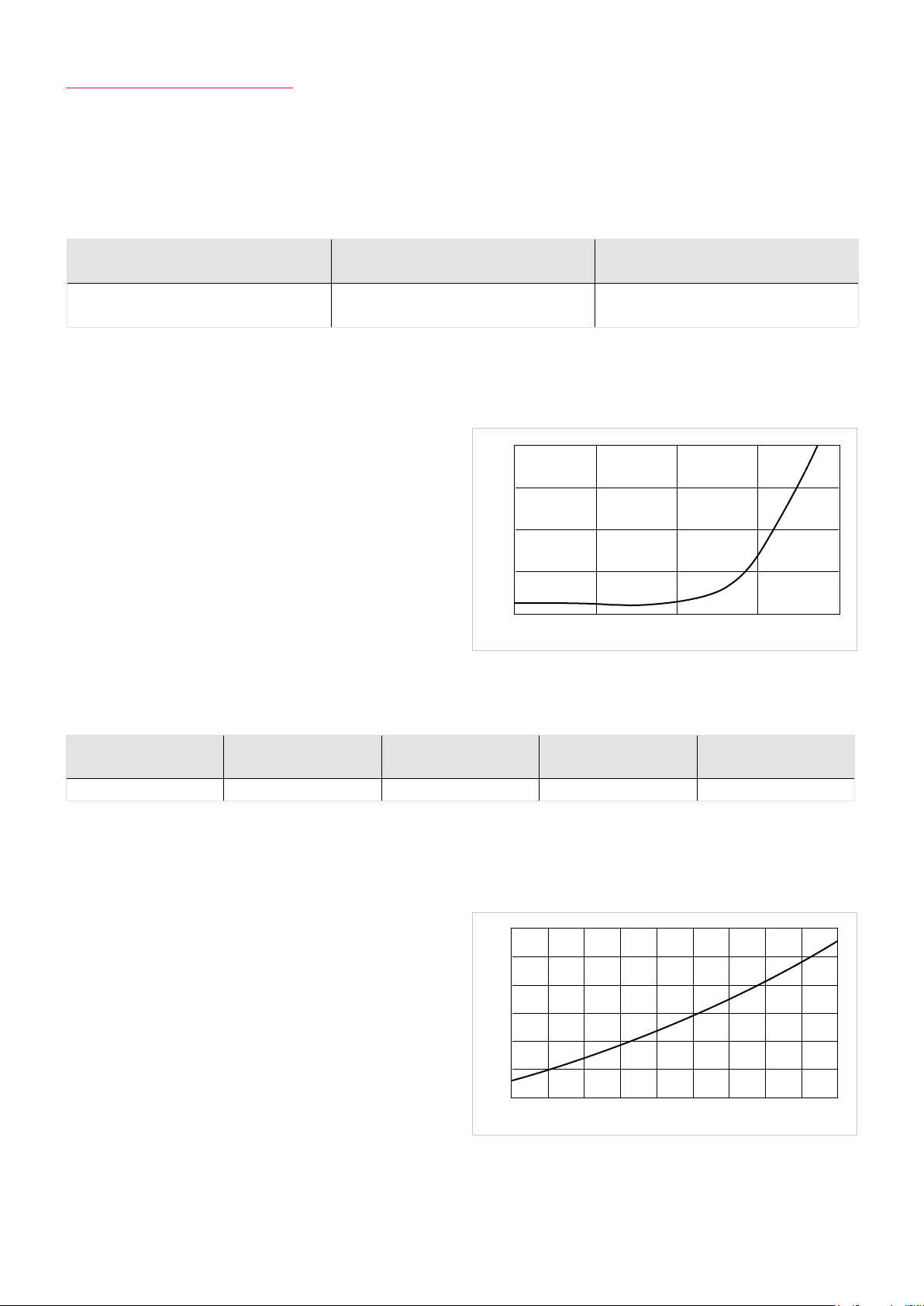
6.23 Temperature Sensors
For motor protection at speeds greater than zero, temperature sensors are integrated in the motor windings. For applications
with high load where the speed is zero, additional protection (e.g. I
Table 62.1
Sensor type Parameter T
PTC Rated operating temperature
PTC thermistors, because of their very high positive temperature coecient at nominal operating temperature (T
nat
),
2
t monitoring) is recommended.
Illustration 62.2
4000
[°C]
Nat
120 (CHA-14A ... 17A)
145 (CHA-20A ... 58A)
Diagram PTC
are ideally suited for motor winding predection.
3000
Due to their principle, the PTC sensors should only be used to
monitor the winding temperature.
2000
Resistance [Ω]
1000
Table 62.3
Sensor type Parameter
KTY 84-130 Temperature T [°C] 80 90
When using the KTY 84-130, the values given in the table
must be parameterized in the servo controller or in an external measurement device.
The KTY sensor is used for temperature measurement and
monitoring the motor winding.
Because the KTY sensor provides an analogue temperature
measurement, it is also possible to predect the actuator
grease from temperature overload.
Symbol
[Unit]
0
T
-5 ° T
NAT
Temperature [ºC]
NAT
Warning Shutdown
Illustration 62.4
1500
1300
1100
900
Resistance [Ω]
700
500
300
-20 0 20 40 60 80 100 120 140 160
Temperature [ºC]
Diagram KTY 84-130
T
+5 °
NAT
62 1018854 8/2018 V03
Page 63
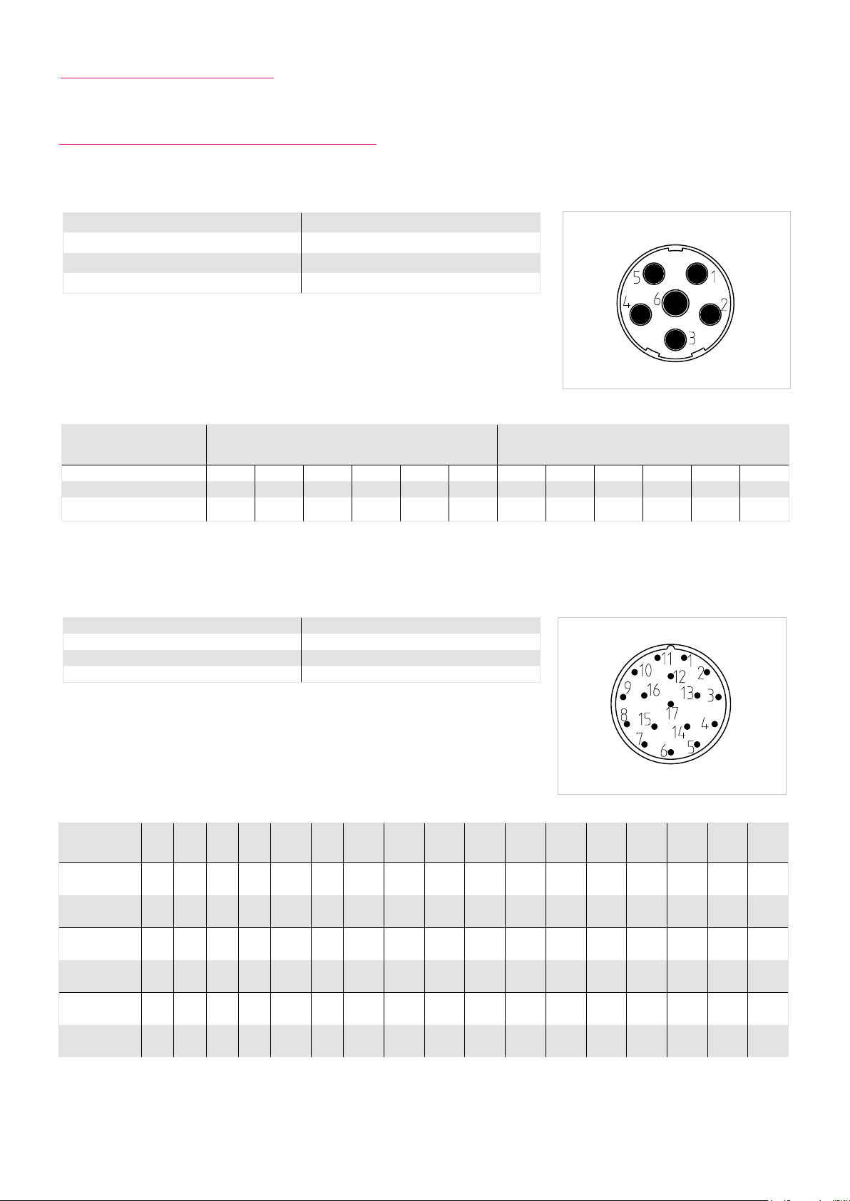
6.24 Electrical Connections
6.24.1 CHA-xx-H-C1024 / H-M512P / H-M128S
Table 63.1
Motor connector 6 / M23 x 1
Cable plug 6 / M23 x 1 / Mat.-no. 301193
External diameter ≈ 26 mm
Length ≈ 60 mm
Table 63.3
CHA-20 / 25 / 32 / 40 / 50 / 58 CHA-14 / 17
Connector pin 1 2 3 4 5 6 1 2 3 4 5 6
Motor phase U V PE BR+ BR- W U V PE BR+ BR- W
Colour red black
Table 63.4
Encoder connector 17 / M23 x 1
Cable plug 17 / M23 x 1 / Mat.-no. 270199
External diameter ≈ 26 mm
Length ≈ 60 mm
green
yellow
white brown white red black
Illustration 63.2
green
yellow
Illustration 63.5
black white white
Table 63.6
Connector pin 1 2 3 4 5 6
C 1024 Signal A+ A- R+ D- C+ C- GND
Colour yellow green red
M512P Signal A+ A- DATA+ – CLOCK+ – GND
Colour yellow green red
M128 Signal
Colour red white green - blue - black
A+
COS+A-COS-
white
blue grey
yellow
white
blue grey
yellow
DATA+ – CLOCK+ – GND
brown
blue
brown
blue
7
(15)
8 9
Temp+
KTY
green
black
Temp+
KTY
green
black
Temp+
KTY
white
brown
Temp-
KTY
green
red
Temp-
KTY
green
red
Temp-
KTY
white
blue
10
(16)
brown
red
brown
red
red black white white white
11 12 13 14
Up B+ B- R- D+
black brown orange
Up B+ B- DATA + CLOCK-
black brown orange
B+
Up
SIN+B-SIN-
white
black
white
black
DATA- CLOCK-
15
(7)16(10)
GND
Sensor
GND
Sensor
GND
Sensor
Up
Sensor
Up
Sensor
Up
Sensor
17
Inner
Shield
Inner
Shield
Inner
shield
631018854 8/2018 V03
Page 64

Connecting cables SINAMICS S120 with SMC modul
Table 64.1
Power Connection
CHA without brake 6FX8002-5CG01-1xx0
CHA with brake 6FX8002-5DG01-1xx0
Motor feedback
H-C1024 6FX8002-2CA31-1xx0
H-M512P
H-M128S
6FX8002-2EQ10-1xx0
Connecting cables with flying leads
Table 64.2
Version Mat.-no. Length [m]
H-C1024
H-M512P
H-M128S
308853
308854
308855
308856
308857
308858
308859
308860
308861
308862
5
10
15
20
25
5
10
15
20
25
Connecting cables for the connection to YukonDrive®
Table 64.3
Version Mat.-no. Length [m]
H-M128S
314260
314261
314262
3
5
10
64 1018854 8/2018 V03
Page 65

6.24.2 CHA-xx-H-RES
Table 65.1
Motor connector 6 / M23 x 1
Cable plug 6 / M23 x 1 / Mat.-no. 301193
External diameter ≈ 26 mm
Length ≈ 60 mm
Table 65.3
CHA-14 / 17
Connector pin 1 2 3 4 5 6
Motor phase U V PE BR+ BR- W
Colour red black
Table 65.4
Encoder connector 12 / M23 x 1
Cable plug 12 / M23 x 1 / Mat.-no. 303494
External diameter ≈ 26 mm
Length ≈ 60 mm
green
yellow
black white white
Illustration 65.2
Illustration 65.5
Table 65.6
Connector pin 1 2 3 4 5 6 7 8 9 10 11 12
RES Signal SIN+ SIN- Vss-
Colour green yellow - - - - violett grey
Temp+
KTY
Temp-
KTY
black
white
Vss+ COS+ COS-
blue black brown
Connecting cables SINAMICS S120 with SMC modul
Table 65.7
Power Connection
CHA without brake 6FX8002-5CG01-1xx0
CHA with brake 6FX8002-5DG01-1xx0
Motor feedback
RES 6FX8002-2CF02-1xx0
651018854 8/2018 V03
Page 66
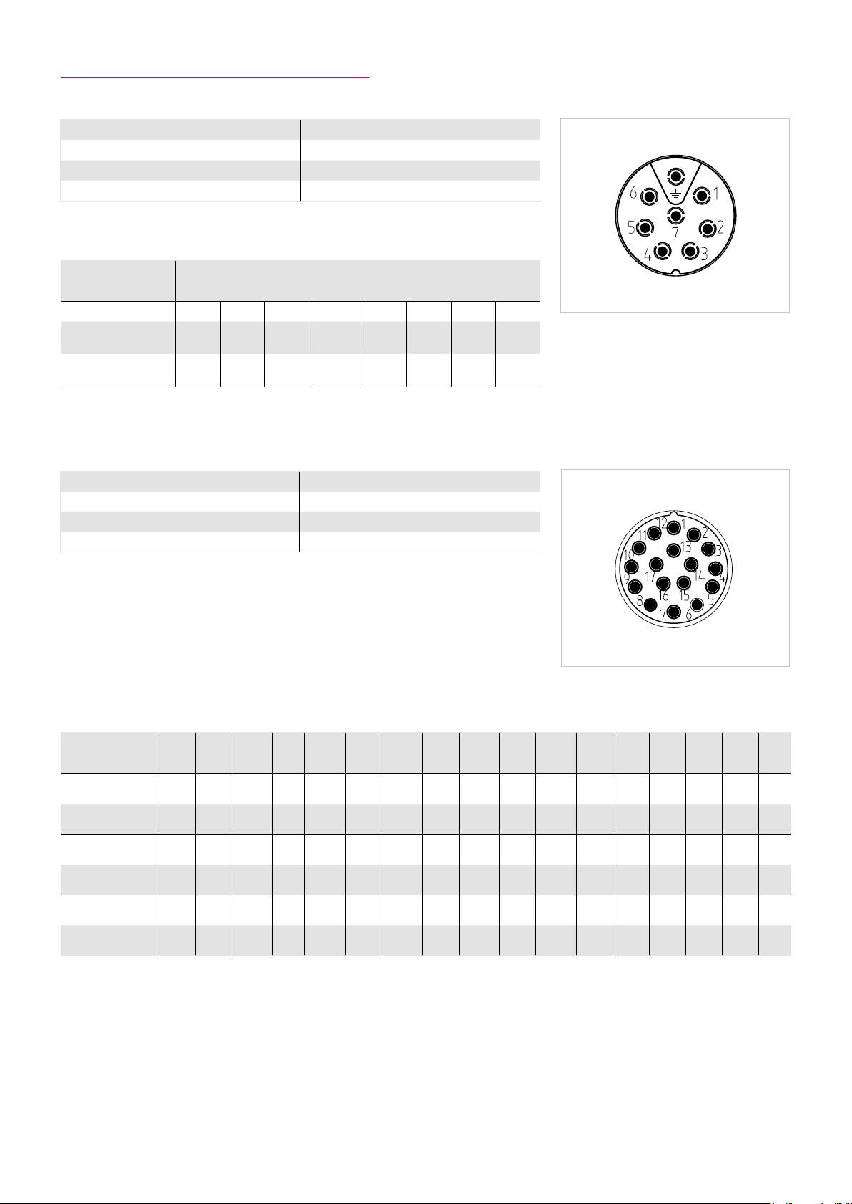
6.24.3 CHA-xx-N-RES / N-M128S / N-D2048
Table 66.1
Motor connector 8 / M17 x 1
Cable plug 8 / M17 x 1 / Mat.-no. 1011445
External diameter ≈ 22 mm
Length ≈ 50 mm
Table 66.3
CHA-14 / 17
Connector pin 1 6 7 PE 3 4 2 5
Motor phase U W V PE BR+ BR-
Colour red white black
Table 66.4
Encoder connector 17 / M17 x 1
Cable plug 17 / M17 x 1 / Mat.-no. 1011446
External diameter ≈ 22 mm
Length ≈ 50 mm
green
yellow
black white blue white
Temp
PTC
Illustration 66.2
Temp
PTC
Illustration 66.5
Table 66.6
Connector pin 1 2 3 4 5 6 7 8 9 10 11 12 13 14 15 16 17
Temp+
RES Signal SIN+ SIN- Vss-
Colour green yellow - - - - violet grey
D2048 Signal U+ U- V+ V- W+ W- GND Up Z+ Z- A+ A- B+ B-
white
white
white
Colour green white
M128S Signal
Colour red white green - blue - black
A+
COS+
black
red
A-
DATA+ – CLOCK+ – GND
COS-
brown
white
black red blue white black white red white
blue
KTY
Temp+
KTY
white
brown
Temp-
KTY
black
white
Temp-
KTY
white
blue
Vss+ COS+ COS-
blue black brown - - - - -
B+
Up
SIN+
red black white white white
B-
SIN-
DATA- CLOCK-
GND
Sensor
Up
Sensor
66 1018854 8/2018 V03
Page 67
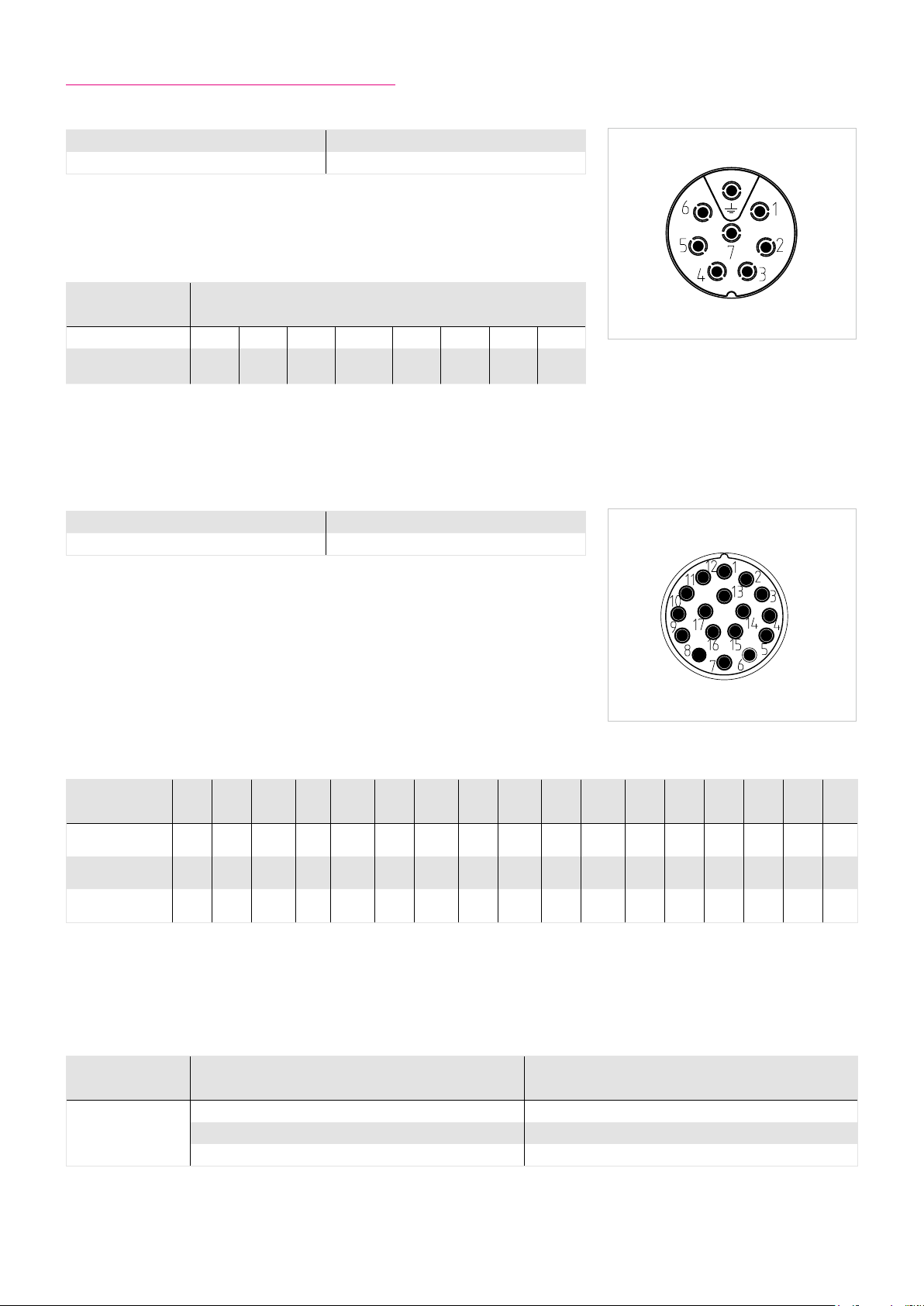
6.24.4 CHA-xx-E-RES / E-M128S / E-D2048
Table 67.1
Motor connector 8 / M17 x 1
Cable plug 8 / M17 x 1 / Mat.-no. 1011445
Table 67.3
CHA-14 / 17
Connector pin 1 6 7 PE 3 4 2 5
Motor phase U W V PE BR+ BR-
Table 67.4
Encoder connector 17 / M17 x 1
Cable plug 17 / M17 x 1 / Mat.-no. 1011446
Temp
PTC
Illustration 67.2
Temp
PTC
Illustration 67.5
Table 67.6
Connector pin 1 2 3 4 5 6 7 8 9 10 11 12 13 14 15 16 17
Temp+
RES Signal SIN+ SIN- Vss-
D2048 Signal U+ U- V+ V- W+ W- GND Up Z+ Z- A+ A- B+ B-
A+
M128S Signal
COS+
A-
DATA+ – CLOCK+ – GND
COS-
KTY
Temp+
KTY
Temp-
KTY
Temp-
KTY
Vss+ COS+ COS-
Temp+
Temp-
KTY
KTY
B+
Up
SIN+
B-
SIN-
DATA- CLOCK-
GND
Sensor
Up
Sensor
Connecting cable set with flying leads
Table 67.7
Variant Mat.-no. Length [m]
1017179 3
E-RES
1017180 5
1017181 10
671018854 8/2018 V03
Page 68
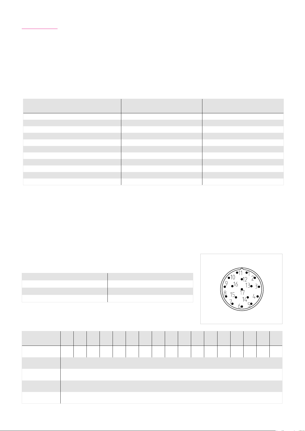
6.25 Options
Position measuring system option EC
The CHA Hollow Shaft Servo Actuators Series are ideally suited for equipping with a single turn absolute measuring system that
can be connected directly to the actuator output.
The ECN 113 single turn absolute encoder is connected to the actuator flange by means of a torsionally sti hollow shaft.
Table 68.1
Ordering code
Symbol
[Unit]
EC
Manufacturer‘s designation ECN 113
Protocol EnDat® 2.2 / 01
Power supply
Current consumption (max. without load)
1)
1)
Incremental signals u
Ub [VDC] 5 ±5 %
I [mA] 180
[Vss] 1
pp
Signal form sinusoidal
Number of pulses n
Absolute position / revolution (motor side)
Accurracy
1)
3)
[SIN / COS] 2048
1
8192
[arcsec] ±20
Resolution of the absolute value (output side) [arcsec] 158
Resolution (output side)
1)
Source: Manufacturer
2)
For interpolation with 8 bit
2)
3)
Increasing position values
- for rotation in clockwise direction, looking at the motor shaft
- for rotation in counter clockwise direction, looking at the output flange
[arcsec] 2.5
The encoder system is connected using a standard signal connector.
The evaluation of the compatibility of the measurement system must be checked
prior to commissioning. The measuring system contains electrostatically sensitive
components, please observe the ESD measures.
Illustration 68.3
Table 68.2
Encoder connector 17 / M23 x 1
Cable plug 17 / M23 x 1 / Mat.-no. 270199
External diameter ≈ 26 mm
Length ≈ 60 mm
Table 68.4
Connector pin 1 2 3 4 5 6 7 8 9 10 11 12 13 14 15 16 17
Signal
Up
Sensor
– –
GND
Sensor
– – Up
CLOCK+ CLOCK-
GND
Inner
shield
B+ B- DATA+ A+ A- DATA-
Connecting Cables
SIMODRIVE 6FX8002-2AD00-1xx0
SINAMICS S 120
(SMC20)
6FX8002-2CH00-1xx0
YukonDrive® Mat.-no. 1010747 (3 m; other length on request)
68 1018854 8/2018 V03
Page 69

7. Actuator Selection Procedure
ADVICE
We will be pleased to make a gear calculation and selection on your behalf.
7.1. Selection Procedure and Calculation Example
Flowchart for actuator selection
Equation 69.1
Confirm the type of servo mechanism
T1 = TL +
2π
60
.
(J
out
+ JL) . n
t
1
2
required: linear motion or rotary motion
Equation 69.2
T
2
T
= TL – ( T1 – TL )
3
T
rms
Equation 69.3
nav =
Equation 69.4
ED =
= T
L
2
2
. t1 + T
T
1
=
| n2 |
. t
2
t1 + t2 + t3 + t
t1 + t2 + t3 + t
2
t1 + t2 + t3 + t
+ | n2 | . t2 + . t
1
+ t2 + t
t
1
3
. t2 + T
p
.
100 %
p
| n2 |
2
Calculate load torque (T
moment of inertia (JL): Equation 70.3 / Equation 70.5
) and
L
Determine speed pattern from duty cycle
2
. t
3
3
p
Tentatively select the required actuator
based upon load conditions
Calculate the required
acceleration torque (T
Equation 69.1
3
Is the required acceleration torque less than
max. output torque of the actuator?
):
1
No
Yes
Determine the torque pattern and
calculate the effective torque
):
(T
rms
Equation 69.2
Calculate average Speed (n
): Equation 69.3
av
Calculate duty factor (ED): Equation 69.4
T
and nav are inside the
rms
Continuous Duty Zone
Yes
Confirm final selection
No
691018854 8/2018 V03
Page 70
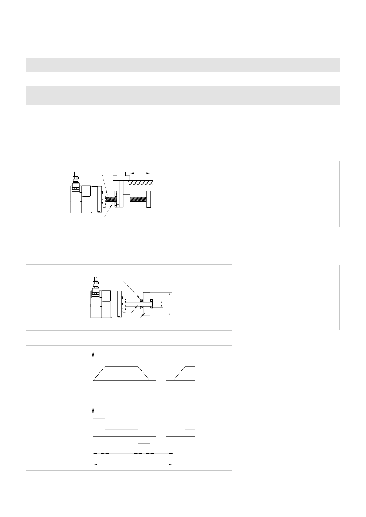
Pre selection conditions
Table 70.1
Load Confirmation Catalogue value Unit
Load max. rotation speed (n
Load moment of inertia (J
1)
JL ≤ 3 . J
is recommended for highly dynamic applications (high responsiveness and accuracy).
Out
) ≤ n
2
) ≤ 3J
L
Linear horizontal motion
Illustration 70.2
Load torque T
[Nm]
L
Ball screw moment of inertia J
Rotary motion
m [kg]
[kgm2]
S
max
1)
Out
Coefficient of friction μ
Pitch P [m]
Efficiency η
Max. output speed [rpm]
Moment of inertia [kgm2]
Equation 70.3
P
JL = JS + m
µ . m . P . g
=
T
L
(
2π . η
2π
2
)
[kgm2]
[Nm]
Illustration 70.4
Illustration 70.6
Speed n [rpm]
Speed pattern
Torque T [Nm]
Torque pattern
Note t1 = t
Coefficient of friction of bearing μ
TL [Nm]
JL [kgm2]
n
2
T
1
T
2
t
1
3
t
2
Operational cycle t
Equation 70.5
m
.
=
[kg]
m
r [m]
D [m]
J
TL = µ . m . g . r [Nm] g = 9.81 [m/s2]
D2 [kgm2]
L
8
Time t [s]
T
3
Time t [s]
t
t
P
3
0
70 1018854 8/2018 V03
Page 71

Example of actuator selection
Load Conditions
Assume servo mechanism is used to cyclically position a mass with a horizontal axis of rotation.
Table 71.1
Load rotation speed n2 = 40 [rpm]
Load torque (e. g. friction) T
Load inertia J
= 5 [Nm]
L
= 1.3 [kgm2]
L
Speed pattern
Acceleration; Deceleration t
Operate with rated speed t
Stand still t
Total cycle time t
Please note: Each characteristic value should be converted to the value at the output shaft of the actuator.
= t3 = 0.1 [s]
1
= 0.1 [s]
2
= 1 [s]
p
= 1.3 [s]
O
Illustration 71.2
Speed n [rpm]
n2= 40 rpm
Time t [s]
Speed pattern
Torque T [Nm]
Torque pattern
Note t
1
= t
3
T
1
t1 = 0.1
T
2
t2 = 0.1
t0 = 1.3
T
t3 = 0.1
3
Actuator data CanisDrive-25A-50
Table 71.3
Max. Torque T
Max. Speed n
Moment of inertia J
tP = 1
Time t [s]
= 127 [Nm]
max
= 112 [rpm]
max
= 1.063 [kgm2]
Out
711018854 8/2018 V03
Page 72
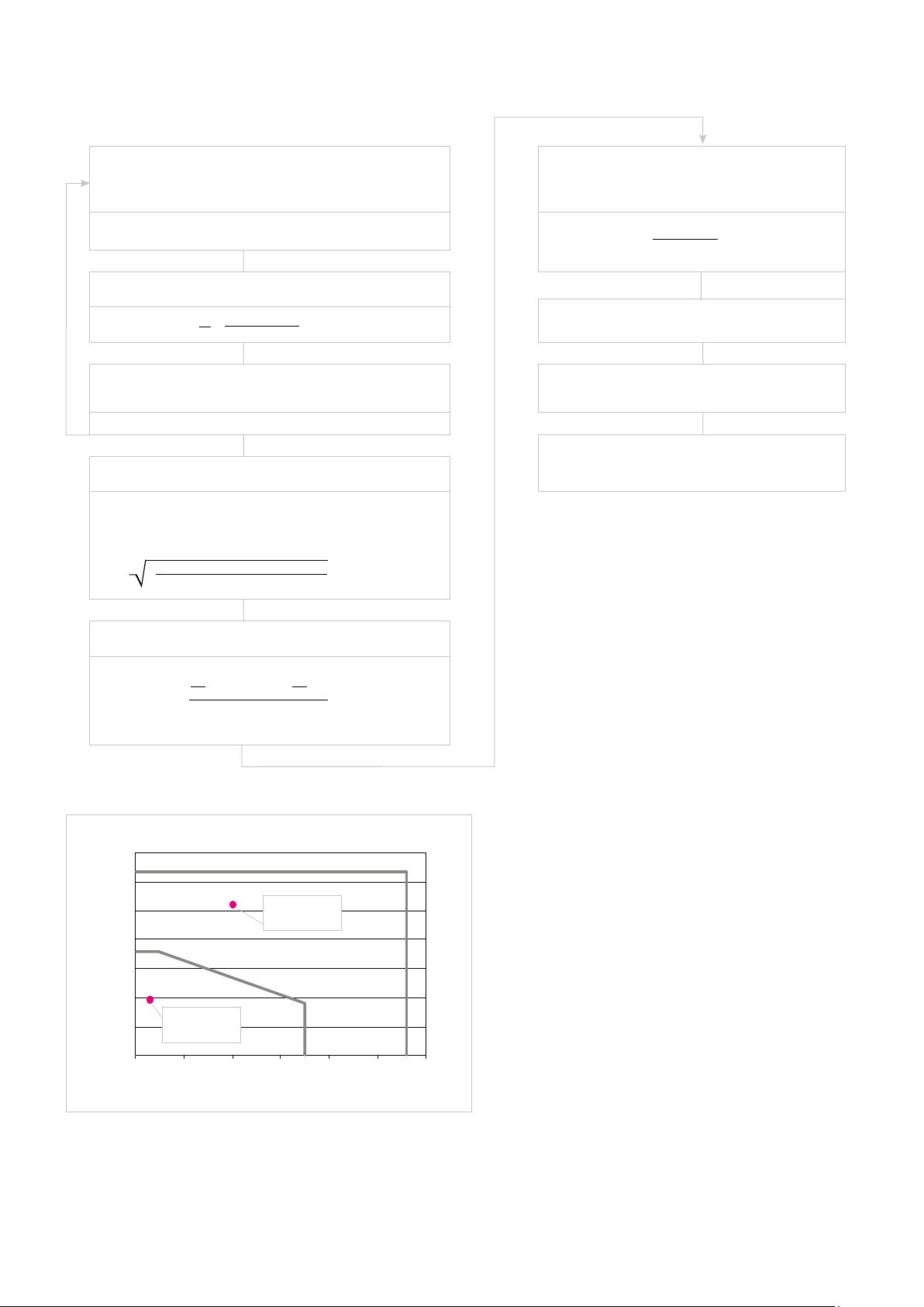
Actuator selection
Tentatively select a required actuator based upon load conditions.
FHA-25C-50 meets the tentative selection requirements from
60 0.1
T
Confirm: Is the required acceleration torque less than
the maximum output torque of the actuator?
No
= 103.8 Nm
T
1
T
= TL = 5 Nm
2
T3 = TL - (T
103.8
T
rms
1
=
1.3
catalogue value (see rating table)
= 40 rpm < n
n
2
JL = 1.3 kgm2 < 3J
= 112 rpm
max
= 3.19 kgm2
out
Calculate required acceleration torque (T
2π · (1.3 + 0.86) · 40
= 5 +
1
T
= 103.8 Nm < T
1
= 103.8 Nm
= 127 Nm
max
Yes
Calculate effective torque (T
) = - 93.8 Nm
- T
L
2
· 0.1 + 52 · 0.1 + (-93.8)2 · 0.1
)
rms
= 38.8 Nm
Calculation of the
duty factor
0.1 + 0.1 + 0.1
ED =
1.3
· 100 %
ED = 23 %
)
1
T
nav = 6 rpm
Check according to the performance characteristics
and nav are inside the continuous duty zone
T
rms
= 38.8 Nm
rms
Confirm final selection
n
Illustration 72.1
140
120
100
80
60
40
Output torque [Nm]
20
0
Calculation of the average speed
.
40
nav =
0.1 + 40 . 0.1 + 40 . 0.1
2
= 6 rpm
av
2
1.3
CanisDrive-25A-50
T1 = 103.8 Nm
n2 = 40 rpm
T
= 38.8 Nm
rms
n
= 6 rpm
av
0 20 40 60 80 100 120
Output speed [rpm]
72 1018854 8/2018 V03
Page 73

7.2 Calculation of the Torsion Angle
Equation 73.1
T ≤ T1
T
φ =
K1
Equation 73.2
T ≤ T
T
1 <
2
T
T - T
1
1
φ =
+
K
K
2
1
Equation 73.3
φ = Angle [rad]
T = Torque [Nm]
K = Stiffness [Nm/rad]
Example
T = 60 Nm K1 = 6.7 . 104 Nm/rad
T1 = 29 Nm K2 = 1.1 . 105 Nm/rad
T2 = 108 Nm K3 = 1.2 . 105 Nm/rad
φ =
T
1
K
1
T > T
2
- T
T
2
+ +
K
2
1
T - T
K
2
3
φ =
.
6.7
φ = 7.15 . 10
29 Nm
104 Nm/rad
-4
rad
60 Nm - 29 Nm
+
.
104 Nm/rad
11
φ = 2.5 arcmin
Equation 73.4
φ [arcmin] = φ [rad]
180 . 60
.
�
731018854 8/2018 V03
Page 74

7.3 Output Bearing
7.3.1 Lifetime Calculation for Continuous Operation
The operating life of the output bearing can be calculated using equation 74.1.
Equation 74.1
with:
L
[h] = Operating life
10
[rpm] = Average output speed
n
6
10
60 . n
.
av
( )
L
=
10
C
fw . P
B
C
av
C [N] =
[N] = Dynamic equivalent load
P
C
f
W
Dynamic load rating,
see table “Output Bearing Ratings“
= Operating factor (Table 74.2)
Average output speed
Table 74.2
Load conditions f
|
n1| t
+
| n
| t
+ ... + | n
1
2
2
n
=
av
t1 + t2 + ... + tn + t
|
t
n
n
p
No impact loads or vibrations 1 ... 1.2
Normal rotating, normal loads 1.2 ... 1.5
Impact loads and/or vibrations 1.5 ... 3
7.3.2 Lifetime Calculation for Oscillating Motion
The operating life at oscillating motion can be calculated using equation 74.3.
Equation 74.3
with:
LOC [h] = Operating life for oscillating motion
[cpm] = Number of oscillations/minute*
n
6
10
180
.
L
=
OC
60 . n
.
ϕ
1
C
(
fw . P
B
)
C
1
C [N] =
[N] = Dynamic equivalent load
P
C
ϕ [Degree] = Oscillating angle
f
W
W
Dynamic load rating. See table “Output Bearing“
in the appropriate product chapter
= Operating factor (Table 74.2)
* one oscillation means 2ϕ
Illustration 74.4
Oscillating angle
Table 74.5
Type of bearing B
Cross roller bearing 10/3
Four point bearing 3
At oscillating angles < 5° fretting corrosion may occur due to insufficient
lubrication. In this case please contact our sales engineer for countermeasures.
Bearing type of selected products see “Output Bearing Ratings“ in the
appropriate product chapter.
74 1018854 8/2018 V03
Page 75
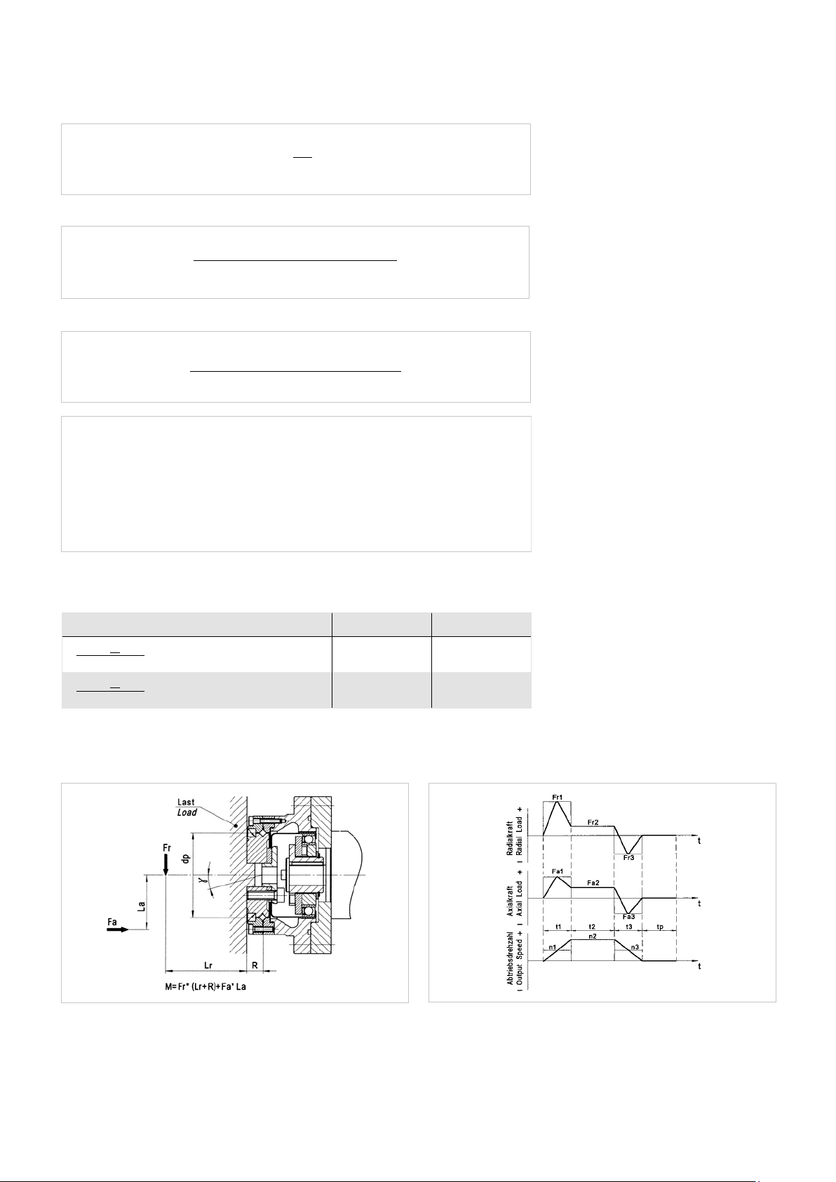
Dynamic equivalent load
Equation 75.1
Equation 75.2
P
= x
C
.
F
+ + y . F
rav
(
2M
dp
aav
)
B
.
.
|
n1 |
t
(|F
1
F
rav
=
(
.
)
1
+ |n2 |
| . t
1
+ |n
t
2
|
2
.
(|F
.
t
2
|
)B + ... + |nn |
r2
+ ... + |
n
|
r1
|
n
| . t
n
B
.
t
n
1/B
.
(|F
|
)
n
rn
)
Equation 75.3
B
.
.
|
n1|
t
(|F
1
F
=
aav
(
.
|
a1
|
n1 |
.
)
+ |
n2 |
t
(|F
|
)B + ... + |nn |
a
2
2
.
t
1
+ |n2 |
.
t
2
+ ... + |nn |
.
t
B
.
t
n
n
1/B
.
(|F
|
)
an
)
with:
F
[N] = Radial force
rav
[N] = Axial force
F
aav
[m] = Pitch circle
d
p
x = Radial load factor (Table 75.4)
y = Axial load factor (Table 75.4)
M = Tilting moment
Table 75.4
Load factors x y
F
aav
F
+ 2 · M / dp
rav
F
+ 2 · M / dp
rav
F
≤ 1.5
aav
> 1.5
1 0.45
0.67 0.67
Illustration 75.5 Illustration 75.6
Please note:
Frx represents the maximum radial force.
Fax represents the maximum axial force.
tp represents the pause time between cycles.
751018854 8/2018 V03
Page 76

7.3.3 Permissible Static Tilting Moment
In case of static load, the bearing load capacity can be determined as follows:
Equation 76.1
and so
Equation 76.2
fs= Static load safety factor
= 1,5 ... 3) (Table 76.3)
(f
s
= Static load rating
C
0
= Fa = 0
F
r
= 1
x
0
= 0.44
y
0
= Static equivalent load
P
0
= Pitch circle diameter of the output bearing
d
p
M
= Moment acting
= Allowable static overturning moment
M
0
C
0
f
=
S
mit P0 = x
P
0
MO =
2M
F
+ + y0 . F
(
r
0
dp . C
2 . f
)
d
p
O
S
a
Table 76.3
Rotation conditions of bearing Lower limit value for f
s
Normal ≥ 1.5
Vibrations / Impacts ≥ 2
High transmission accuracy ≥ 3
7.3.4 Angle of Inclination
The angle of inclination of the output flange, as a function of the tilting moment acting on the output bearing, can be
calculated by means of equation 76.1:
Equation 76.1
M
γ =
K
B
with:
γ [arcmin] = Angle of inclination of the output flange
M [Nm] = Tilting moment acting on the output bearing
KB [Nm/arcmin] = Moment stiffness of the output bearing
76 1018854 8/2018 V03
Page 77

8. Design Notes
8.1 Notes on the Fit Selection
For the mechanical design we recommend the following fit selection.
Table 77.1
Unit CHA-14A CHA-17A CHA-20A CHA-25A CHA-32A CHA-40A CHA-50A CHA-58A
Load side
Fit of bearing inner ring [mm] 49 h7 59 h7 69 h7 84 h7 110 h7 132 h7 168 h7 193 h7
Recomended tolerance area for transition fit [mm] H7 H7 H7 H7 H7 H7 H7 H7
Housing side
Fit of bearing outer ring [mm] 78 h7 88 h7 98 h7 116 h7 148 h7 180 h7 222 h7 255 h7
Recomended tolerance area for transition fit [mm] H7 H7 H7 H7 H7 H7 H7 H7
771018854 8/2018 V03
Page 78

9. Installation and Operation
9.1 Transport and Storage
The transportation of the servo actuators and motors should always be in the original packaging.
If the servo actuators and motors are not put into operation immediately after delivery, they should be stored in a dry, dust
and vibration free environment. Storage should be for no longer than 2 years at room temperatures (between +5 °C ... +40 °C)
so that the grease life is preserved.
INFORMATION
Tensile forces in the connecting cable must be avoided.
ADVICE
Lithium metal batteries are dangerous goods according to UN 3090. Therefore they are generally subject to transport
regulations, depending on the transport mode.
The batteries installed in the motor feedback systems do not contain more than 1 g of lithium or lithium alloy and are exempt
from dangerous goods regulations.
9.2 Installation
Check the performance and protection and check the suitability of the conditions at the installation site. Take suitable constructive measures to ensure that no liquid (water, drilling emulsion, coolant) can penetrate the output bearing or encoder
housing.
ADVICE
The installation must be protected against impact and pressure on the gear.
The mounting must be such that heat loss can be adequately dissipated.
No radial forces and axial forces may act to the protection sleeve of the hollow shaft actuator.
During installation, the actuator must be fitted ensuring the machine housing can be rotated without terminals. Already low
terminals may aect the accuracy of the gear and, should this be the case, the installation of the machine housing should be
checked.
78 1018854 8/2018 V03
Page 79

9.3 Mechanical Installation
The data necessary for mounting the actuator and for connecting to the load are given in table 79.1.
Table 79.1
Unit CHA-14A CHA-17A CHA-20A CHA-25A CHA-32A CHA-40A CHA-50A CHA-58A
Load assembly
Number of screws 12 12 12 12 12 12 12 12
Screw size M3 M4 M4 M5 M6 M8 M10 M10
Screw quality 12.9 12.9 12.9 12.9 12.9 12.9 12.9 12.9
Pitch circle diameter [mm] 43 52 62 76 96 118 152 175
Screw tightening torque [Nm] 2.3 5.1 5.1 10 17 42 83 83
Transmittable torque [Nm] 85 188 228 463 847 1964 4086 4688
Housing assembly
Number of screws 8 12 12 12 12 12 12 12
Screw size M3 M3 M3 M4 M5 M6 M8 M10
Screw quality 12.9 12.9 12.9 12.9 12.9 12.9 12.9 12.9
Pitch circle diameter [mm] 68 80 89 105 135 168 206 236
Screw tightening torque [Nm] 2.3 2.3 2.3 5.1 10 17 42.2 83
Transmittable torque [Nm] 89 158 177 378 805 1482 3419 6317
Data valid for completely degreased connecting interfaces (friction coecient μ = 0.15). Screws to be secured against loosening. We recommend LOCTITE 243 to secure screws.
791018854 8/2018 V03
Page 80

9.4 Electrical Installation
All work should be carried out with power o.
Electric servo actuators and motors have dangerous live and rotating parts. All work during connection, operation, repair and
disposal must be carried out only by qualified personnel as described in the standards EN 50110-1 and IEC 60364! Before starting any work, and especially before opening covers, the actuator must be properly isolated. In addition to the main circuits,
the user also has to pay attention to any auxilliary circuits.
Observing the five safety rules:
• Disconnect mains
• Prevent reconnection
• Test for absence of harmful voltages
• Ground and short circuit
• Cover or close o nearby live parts
The measures taken above must only be withdrawn when the work has been completed and the device is fully assembled.
Improper handling can cause damage to persons and property. The respective national, local and factory specific regulations
must be adhered to.
DANGER
DANGER
Due to the fact that the motor contains permanent magnets, a voltage is generated at the motor terminals when the rotor is
turned.
ADVICE
• The connecting leads should be suitable for the type of use, as well as the voltages and amperages concerned.
• The protective earth must be connected to the terminal marked PE.
• All cables used should be provided with a shield and in addition, the encoder cable should feature twisted pair leads.
• The power supply is switched o before connecting and disconnecting the power connection and signal connections.
ADVICE
Encoders and sensors contain electrostatically sensitive components, observe the ESD measures!
80 1018854 8/2018 V03
Page 81
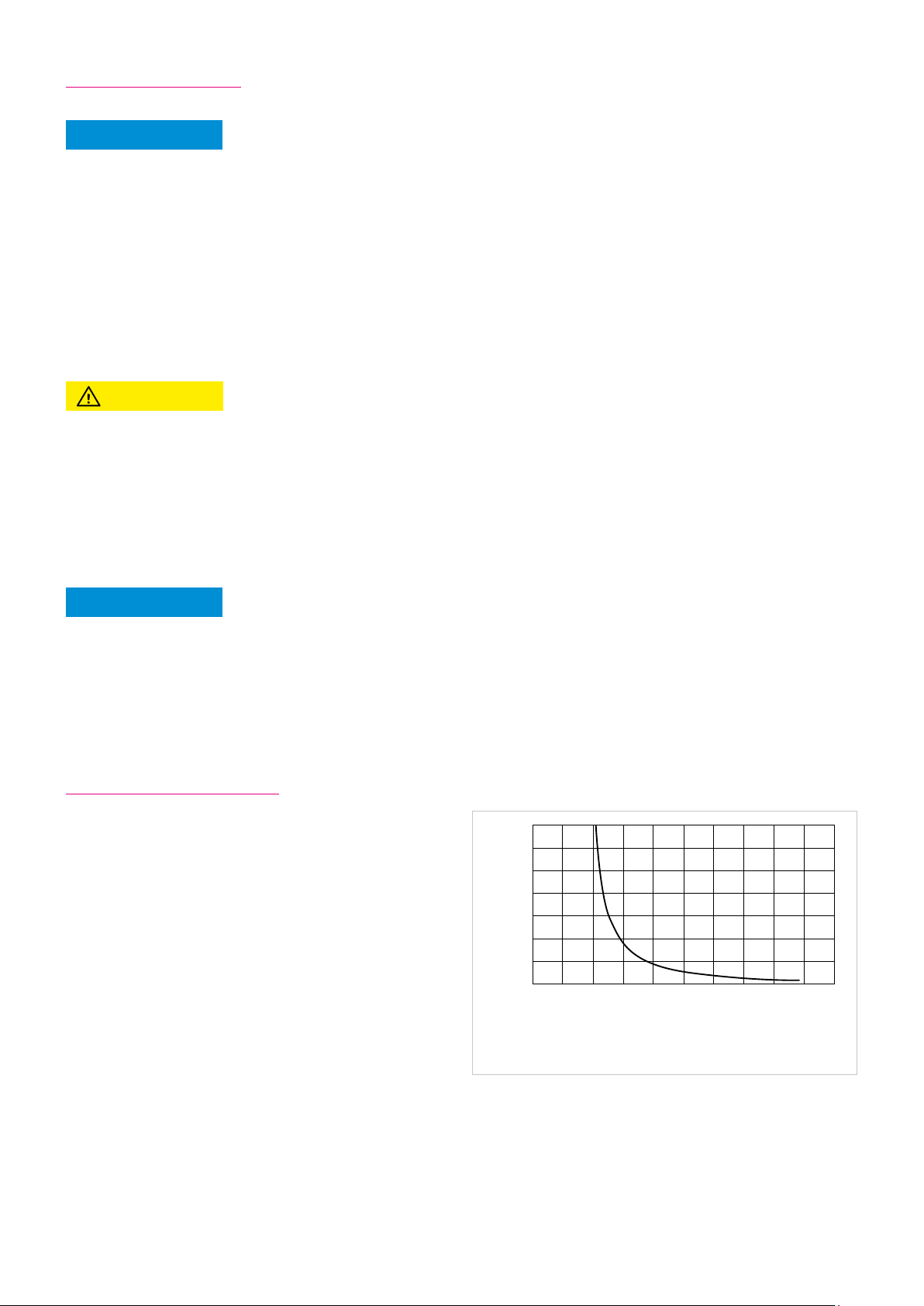
9.5 Commissioning
NOTE
Commissioning must be executed in accordance with the documentation of Harmonic Drive AG.
Before commissioning, please check that:
• The actuator is properly mounted
• All electrical connections and mechanical connections are designed according to requirements
• The protective earth is properly connected
• All attachments (brakes, etc) are operational
• Appropriate measures have been taken to prevent contact with moving and live parts
• The maximum speed n
is specified and cannot be exceeded
max
• The set up of the drive parameters has been executed
• The commutation is adjusted correctly
ATTENTION
Check the direction of rotation of the load uncoupled.
In the event of changes in the normal operating behaviour, such as increased temperature, noise or vibration, switch the actuator o. Determine the cause of the problem and contact the manufacturer if necessary. Even if the actuator is only on test,
do not put safety equipment out of operation.
This list may not be complete. Other checks may also be necessary.
ADVICE
Due to heat generation from the actuator itself, tests outside the final mounting position should be limited to 5 minutes of
continuous running at a motor speed of less than 1000 rpm.
These values should not be exceeded in order to avoid thermal damage to the actuator.
9.6 Overload Protection
To protect the servo actuators and motors from temperature
overload sensors are integrated into the motor windings.
The temperature sensors alone do not guarantee motor
protection. Protection against overload of the motor winding
is only possible with an input speed > 0. For special applications (eg. load at standstill or very low speed) is an additional
overload protection by limiting the overload period.
The built specification of the integrated temperature sensors
can be found in the technical data.
Illustration 81.1
70,00
60,00
50,00
40,00
30,00
time [s]
20,00
10,00
0,00
0,00 0,50 1,00 1,50 2,00 2,50 3,00 3,50 4,00 4,50 5,00
Over load characteristic
I / Is
In addition, it is recommended to protect the motor winding
against overload by the use of I²t monitoring integrated in
the controller. The graph shows an example of the overload
characteristic for the I²t monitoring. The overload factor is
the ratio between the actual RMS current and continuous
stall current.
ls = Continuous stall current
l = Actual effective current (l ≤ l
)
max
811018854 8/2018 V03
Page 82

9.7 Protection against Corrosion and Penetration of Liquids and Debris
The product is fully protected provided that the connectors are correctly attached. Corrosion from the ambient atmosphere
(condensation, liquids and gases) at the running surface of the output shaft seal is prevented.
Contact between sharp edged or abrasive objects (cutting chips, splinters, metallic or minerals dusts, etc.) and the output
shaft seal must be prevented. Permanent contact between the output shaft seal and a permanent liquid covering should also
be prevented.
A change in the operating temperature of a completely sealed actuator can lead to a pressure dierential between the outside and the inside temperature of the actuator. This can cause any liquid covering the output shaft seal to be drawn into the
housing which could cause corrosive damage.
As a countermeasure, we recommend the use of an additional shaft seal (to be provided by the user) or the maintenance of a
constant pressure inside the actuator. Please contact Harmonic Drive AG for further information.
ADVICE
Specification sealing air: constant pressure in the actuator as described above; the supplied air must be dry and filtered
with pressure at not more than 104 Pa.
9.8 Shutdown and Maintenance
In case of malfunctions or maintenance measures, or to shutdown the motors,
proceed as follows:
1. Follow the instructions in the machine documentation.
2. Bring the actuator on the machine to a controlled standstill.
3. Turn o the power and the control voltage on the controller.
4. For motors with a fan unit; turn o the motor protection switch for the fan unit.
5. Turn o the mains switch of the machine.
6. Secure the machine against accidental movement and against unauthorised operation.
7. Wait for the discharge of electrical systems then disconnect all the electrical connections.
8. Secure the motor, and possibly the fan unit, before disassembly against falling or movement then pay attention to the
mechanical connections.
82 1018854 8/2018 V03
Page 83

DANGER
Risk of death by electric voltages. Work in the area of live parts is extremely dangerous.
• Work on the electrical system may only be performed by qualified electricians. The use of a power tool is absolutely
necessary.
Observing the five safety rules:
• Disconnect mains
• Prevent reconnection
• Test for absence of harmful voltages
• Ground and short circuit
• Cover or close o nearby live parts
• Before starting work check with a suitable measuring instrument if there are any parts under residual voltage.(e.g.
capacitors, etc.). Wait until the residual voltage is within a save range.
The measures taken above must only be withdrawn when the work has been completed and the device is fully assembled.
Improper handling can cause damage to persons and property. The respective national, local and factory specific regulations
must be adhered to.
ATTENTION
Burns from hot surfaces with temperatures of over 100 °C
Let the motors cool down before starting work. Cooling times of up to 140 minutes may be necessary.
Wear protective gloves.
Do not work on hot surfaces!
WARNING
Persons and property during maintenance and operation
Never perform maintenance work on running machinery. Secure the system during maintenance against re-starting and
unauthorised operation.
Cleaning
Excessive dirt, dust or chips may adversely aect the operation of the device and can, in extreme cases, lead to failure. At
regular intervals (latest after one year) you should therefore, clean the device to ensure a sucient dissipation of the surface
heat. Insucient heat emissions can have undesirable consequences. The lifetime of the device is reduced if temperature
overloads occures. Overtemperature can lead to the shutdown of the device.
831018854 8/2018 V03
Page 84

Checking of electric connections
Lethal electric shock by touching live parts!
In any case of defects of the cable sheath the system must be shut down immediately and the damaged cable should be
replaced. Do not make any temporary repairs on the connection cables.
• Connection cord should be periodically checked for damage and replaced if necessary.
• Check optionally installed power chains for defects.
• Protective conductor connections should be in a good condition and tightness checked at regular intervals.
Replace if necessary.
DANGER
Control of mechanical fasteners
The fastening screws and the load of the housing must be checked regularly.
Maintenance intervals for battery backed motor feedback systems
ADVICE
Please note the information on battery life time in the chapter "Motor Feedback Systems"!
10. Decommissioning and Disposal
The gears, servo actuators and motors from Harmonic Drive AG contain lubricants for bearings and gears as well as electronic
components and printed circuit boards. Since lubricants (greases and oils) are considered hazardous substances in accordance
with health and safety regulations, it is necessary to dispose of the products correctly. Please ask for safety data sheet where
necessary.
ADVICE
• Batteries do not contain hazardous materials according to EC directives 91/157/EEC, 93/86/EEC, and 2011/65/EU
(RoHS directive)
• EC battery directive 2006/66/EC has been implemented by most EC member states,
• According to the EU Battery Directive, Lithium batteries are marked with the symbol of the crossedout wheeled bin
(see figure). The symbol reminds the end user that batteries are not permitted to be disposed of with household waste, but
must be collected separately.
• A disposal service is oered upon request by Harmonic Drive AG.
84 1018854 8/2018 V03
Page 85
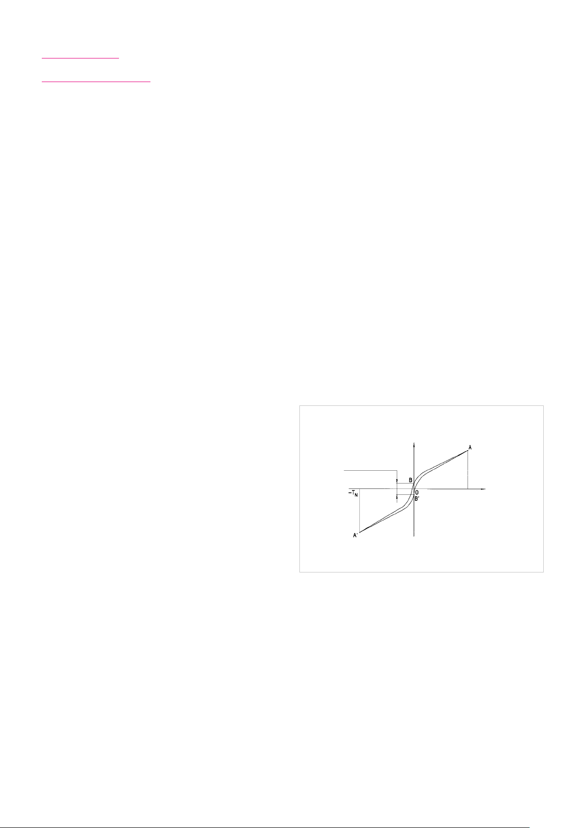
11. Glossary
11.1 Technical Data
AC Voltage constant kEM [V
Eective value of the induced motor voltage measured at the motor terminals at a speed of 1000 rpm and an operating temperature of 20 °C.
/ 1000 rpm]
rms
Ambient operating temperature [°C]
The intended operating temperature for the operation of the drive.
Average input speed (grease lubrication) n
Maximum permissible average gear input speed for grease lubrication. The applications average input speed must be lower than
the permitted average input speed of the gear.
Average input speed (oil lubrication) n
Maximum permissible average gear input speed for oil lubrication. The applications average input speed must be lower than
the permitted average input speed of the gear.
av (max)
av (max)
[rpm]
[rpm]
Average torque TA [Nm]
When a variable load is applied to the gear, an average torque should be calculated for the complete operating cycle. This
value should not exceed the specified TA limit.
Backlash (Harmonic Planetary Gears) [arcmin]
When subjected to the rated torque, Harmonic Planetary
Gears display characteristics shown in the hysteresis curve.
When a torque is applied to the output shaft of the gear
with the input shaft locked, the torque-torsion relationship
can be measured at the output. Starting from point 0 the
graph follows successive points A-B-A'-B'-A where the value
B-B' is defined as the backlash or hysteresis.
Hysteresis loss/
Backlash
Brake closing time tC [ms]
Delay time to close the brake.
Brake current to hold I
Current for applying the brake.
Brake current to open I
Current required to open the brake.
HBr
OBr
[ADC]
[ADC]
Brake holding torque TBR [Nm]
Torque the actuator can withstand when the brake is applied, with respect to the output.
Torsion
φ
Torque T +T
T
= Rated torque
N
φ = Output angle
N
Brake opening time tO [ms]
Delay time for opening the brake.
851018854 8/2018 V03
Page 86
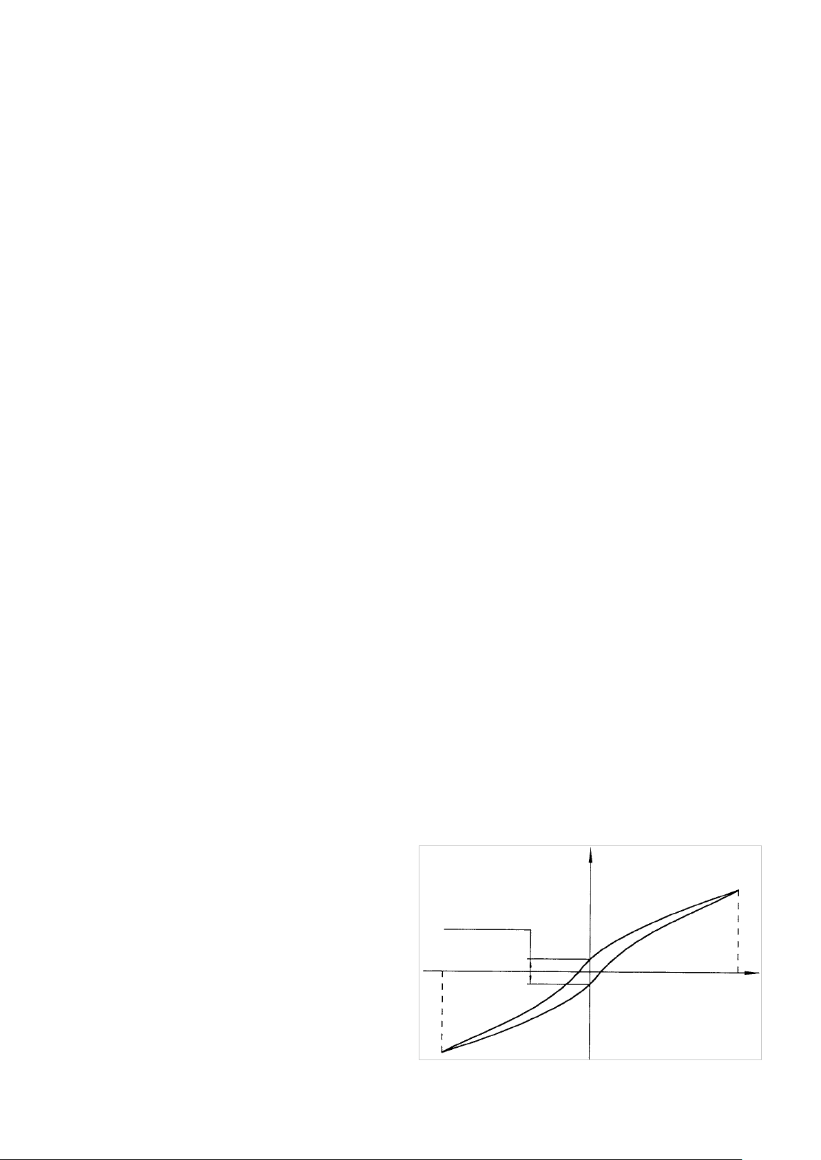
Brake voltage UBr [VDC]
Terminal voltage of the holding brake.
Continuous stall current I0 [A
rms
]
Eective value of the motor phase current to produce the stall torque.
Continuous stall torque T0 [Nm]
Allowable actuator stall torque.
Demagnetisation current IE [A
rms
]
Current at which rotor magnets start to demagnetise.
Dynamic axial load F
A dyn (max)
[N]
With the bearing rotating, this is the maximum allowable axial load with no additional radial forces or tilting moments
applied.
Dynamic load rating C [N]
Maximum dynamic load that can be absorbed by the output bearing before permanent damage may occur.
Dynamic radial load F
R dyn (max)
With the bearing rotating, this is the maximum allowable radial load with no additional axial forces or tilting moments
applied.
[N]
Dynamic tilting moment M
dyn (max)
[Nm]
With the bearing rotating, this is the maximum allowable tilting moment with no additional axial forces or radial forces
applied. This value is not based on the equation for lifetime calculation of the output bearing but on the maximum allowable
deflection of the Harmonic Drive® Component Set. This value must not be exceeded even if the lifetime calculation of the
bearing permits higher values.
Electrical time constant τe [s]
The electrical time constant is the time required for the current to reach 63 % of its final value.
Hollow shaft diameter dH [mm]
Free inner diameter of the axial hollow shaft.
Hysteresis loss (Harmonic Drive® Gears)
When a torque is applied to the output of a Harmonic Drive®
Gear with the input locked, the torque-torsion relationship
measured at the output typically follows, starting from point
0, the successive points the hysteresis curve A-B-A'-B'-A
(see figure). The value of the displacement B-B' is defined as
the hysteresis loss.
Hysteresis loss
-T
N
Torsion
φ
A
B
0
B‘
Torque T + TN
A‘
TN = Rated output torque
φ = Output rotation angle
86 1018854 8/2018 V03
Page 87

Inductance (L-L) L
[mH]
L- L
Terminal inductance calculated without taking into account the magnetic saturation of the active motor parts.
Lost Motion (Harmonic Drive® Gears) [arcmin]
Harmonic Drive® Gears exhibit zero backlash in the teeth.
Lost motion is the term used to characterise the torsional
stiness in the low torque region.
Torsion
φ
The illustration shows the angle of rotation ϕ measured
against the applied output torque as a hysteresis curve with
the Wave Generator locked. The lost motion measurement of
the gear is taken with an output torque of about ±4 % of the
Lost Motion
φ
φ1 ; φ
2
; φ
1‘
2‘
Torque T
rated torque.
N
~ +4 % T
N
Maximum current I
max
~ -4 % T
[A]
The maximum current is the maximum current that can be applied for a short period.
Maximum DC bus voltage U
DC (max)
[VDC]
The maximum DC bus power supply for the correct operation of the actuator. This value may only be exceeded for a short
period during the braking or deceleration phase.
Maximum hollow shaft diameter d
H (max)
[mm]
For gears with a hollow shaft, this value is the maximum possible diameter of the axial hollow shaft.
Maximum input speed (grease lubrication) n
in (max)
[rpm]
Maximum allowable input speed with grease lubrication for short period. The maximum input speed can be applied as often
as desired, as long as the application's average speed is lower than the permitted average input speed of the gear.
Maximum input speed (oil lubrication) n
in (max)
[rpm]
Maximum allowable input speed for gearing with oil lubrication for short period. The maximum input speed can be applied as
often as desired, as long as the application's average speed is lower than the permitted average input speed of the gear.
Maximum motor speed n
max
[rpm]
The maximum allowable motor speed.
Maximum output speed n
max
[rpm]
The maximum output speed. Due to heating issues, this may only be momentarily applied during the operating cycle. The
maximum output speed can occur any number of times as long as the calculated average speed is within the permissible
continuous operation duty cycle.
Maximum output torque T
max
[Nm]
Specifies the maximum allowable acceleration and deceleration torques. For highly dynamic processes, this is the maximum
torque available for a short period. The maximum torque can be parameterised by the control unit where the maximum
current can be limited. The maximum torque can be applied as often as desired, as long as the calculated average torque is
within the permissible continuous operation duty cycle.
871018854 8/2018 V03
Page 88

Maximum power P
Maximum power output.
max
[W]
Mechanical time constant τm [s]
The mechanical time constant is the time required to reach 63 % of its maximum rated speed in a no-load condition.
Momentary peak torque TM [Nm]
In the event of an emergency stop or collision, the Harmonic Drive® Gear may be subjected to a brief momentary peak torque.
The magnitude and frequency of this peak torque should be kept to a minimum and under no circumstances should the
momentary peak torque occur during the normal operating cycle. The allowable number of momentary peak torque events
can be calculated with the equations given in chapter "selection procedure".
Moment of inertia J [kgm²]
Mass moment of inertia at motor side.
Moment of inertia Jin [kgm²]
Mass moment of inertia of the gear with respect to the input.
Moment of inertia J
Mass moment of inertia with respect to the output.
Motor terminal voltage (Fundamental wave only) UM [V
Required fundamental wave voltage to achieve the specified performance. Additional power losses can lead to restriction of
the maximum achievable speed.
[kgm2]
out
rms
]
Nominal Service Life Ln [h]
When loaded with rated torque and running at rated speed the Wave Generator Bearing will reach the nominal service life Ln
with 50 % propability of failure. For dierent load conditions the service life of the Wave Generator Bearing can be calculated
using the equations in chapter "selection procedure".
Number of pole pairs p
Number of magnetic pole pairs on the rotor of the motor.
Oset R [m]
Distance between output 's center plane and contact point of the load.
Pitch circle diameter dp [m] or [mm]
Pitch circle diameter of the output bearing rolling element raceway.
Protection class IP
The degree of protection according to EN 60034-5 provides suitability for various environmental conditions.
Rated current IN [A]
RMS value of the sinusoidal current when driven at rated torque and rated speed.
Rated motor speed nN [rpm]
The motor speed which can be continuously maintained when driven at rated torque TN, when mounted on a suitably dimensioned heat sink.
88 1018854 8/2018 V03
Page 89

Rated power PN [W]
Output power at rated speed and rated torque.
Rated speed nN [rpm], Servo
The output speed which can be continuously maintained when driven at rated torque TN, when mounted on a suitably
dimensioned heat sink.
Rated speed nN [rpm], Mechanical
The rated speed is a reference speed for the calculation of the gear life. When loaded with rated torque and running at
rated speed the Wave Generator Bearing will reach the nominal service life Ln with 50 % propability of failure. The rated speed
nN is not used for the dimensioning of the gear.
[rpm]
Product series n
N
CobaltLine®, HFUC, HFUS, CSF, CSG, CSD, SHG, SHD 2000
PMG size 5 4500
PMG size 8 to 14 3500
HPG, HPGP, HPN 3000
Rated torque TN [Nm], Servo
The output torque which can be continuously transmitted when driven at rated input speed, when mounted on a suitably
dimensioned heat sink.
Rated torque TN [Nm], Mechanical
The rated torque is a reference torque for the calculation of the gear life. When loaded with rated torque and running at rated
speed the Wave Generator Bearing will reach the nominal service life Ln with 50 % propability of failure. The rated torque TN is
not used for the dimensioning of the gear.
Rated voltage UN [V
Supply voltage for operation with rated torque and rated speed.
rms
]
Ratio i [ ]
The ratio is the reduction of input speed to the output speed.
Note for Harmonic Drive® Gears: In the standard drive arrangement, the Wave Generator is the drive element while the Flexspline is the driven element and the Circular Spline is fixed to the housing. Since the direction of rotation of the input (Wave
Generator) is opposite to the output (Flexspline), a negative ratio must be considered.
Repeatability [arcmin]
The repeatability of the gear describes the position dierence measured during repeated movement to the same
desired position from the same direction. The repeatability is
defined as half the value of the maximum dierence measured, preceded by a ± sign.
Repeatability = ±x/2
φ2
x/2
φ1
φ7
x
x/2
891018854 8/2018 V03
Page 90

Repeated peak torque TR [Nm]
Specifies the maximum allowable acceleration and deceleration torque. During the normal operating cycle the repeatable peak
torque TR must not be exceeded. The repeated peak torque can be applied as often as desired, as long as the application's
average torque is lower than the permitted average torque of the gear.
Resistance (L-L, 20 °C) R
Winding resistance measured between two conductors at a winding temperature of 20 °C.
L- L
[Ω]
Size
1) Actuators / Gears with Harmonic Drive® Gears or Harmonic Planetary Gears
The frame size is derived from the pitch circle diameter of the gear teeth in inches multiplied by 10.
2) CHM Servo Motor Series
The size of the CHM Servo Motors is derived from the stall torque in Ncm.
3) Direct drives from the TorkDrive® Series
The size of the TorkDrive® Series is the outer diameter of the iron core of the stator.
Static load rating C0 [N]
Maximum static load that can be absorbed by the output bearing before permanent damage may occur.
Static tilting moment M0 [Nm]
With the bearing stationary, this is the maximum allowable radial load with no additional axial forces or tilting moments
applied.
Synchronous inductance Ld [mH]
Sum of air gap inductance and leakage inductance in relation to the single-phase equivalent circuit diagram of the
synchronous motor.
Tilting moment stiness KB [Nm/arcmin]
The ratio of the tilting angle of the output bearing and the applied moment load.
Torque constant (motor) kTM [Nm/A
Quotient of stall torque and stall current.
Torque constant (output) k
Quotient of stall torque and stall current, taking into account the transmission losses.
[Nm/A
Tout
rms
rms
]
]
90 1018854 8/2018 V03
Page 91
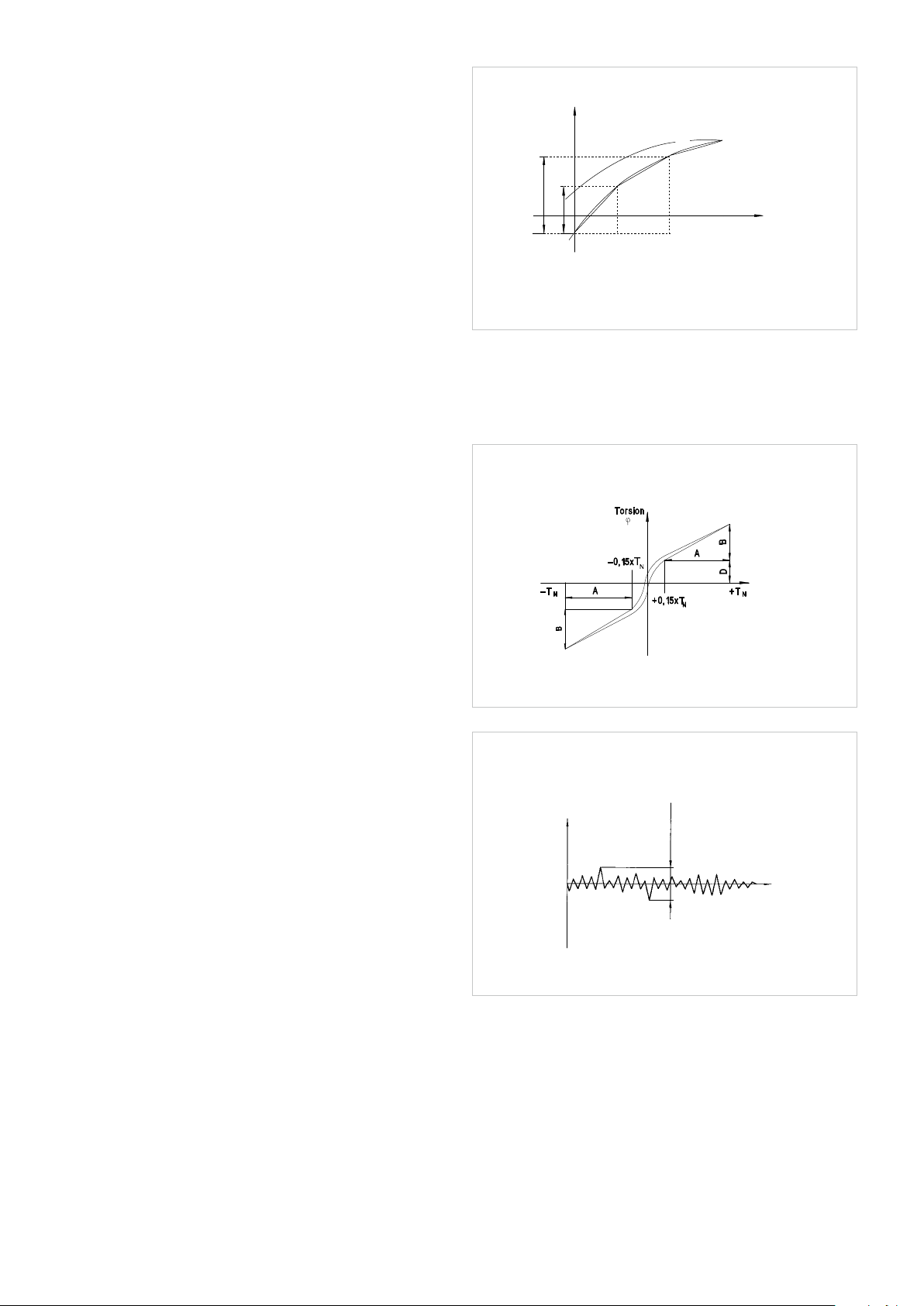
Torsional stiness
(Harmonic Drive® Gears) K1, K2, K3 [Nm/rad]
The amount of elastic rotation at the output for a given
torque with the Wave Generator blocked. The torsional stiness may be evaluated by dividing the torque-torsion curve
into three regions. The torsional stiness values K1, K2 and K3
are determined by linearization of the curve.
K1: low torque region 0 ~ T
K2: middle torque region T1 ~ T
1
2
K3: high torque region > T3
The values given for the torsional stiness K1, K2 and K3 are
average values that have been determined during numerous
tests. The limit torques T1 and T2 and an calculation example
for the torsional angle can be found in chapter "torsional
stiness" and "calculation of the torsion angle" of this
documentation.
Torsional stiness
(Harmonic Planetary Gears) K3 [Nm/rad]
The amount of elastic rotation at the output for a given
torque and blocked input shaft. The torsional rigidity of the
Harmonic Planetary Gear describes the rotation of the gear
above a reference torque of 15 % of the rated torque. In this
area the torsional stiness is almost linear.
Torsion
φ
K
3
φ2
φ1
, K2, K3 = Torsional stiness, w = Output angle
K
1
φ1 = Torsion angle, with output torque T
φ2 = Torsion angle, with output torque T
K
2
K
1
Torque T
0
T
T
1
2
1
2
TN = Rated torque
φ = Output angle
Transmission accuracy [arcmin]
The transmission accuracy of the gear represents the linearity error between input and output angle. The transmission
accuracy is measured for one complete output revolution
using a high resolution measurement system. The measurements are carried out without direction reversal. The trans-
Transmission
mission accuracy is defined as the sum of the maximum
accuracy
positive and negative dierences between the theoretical
and actual output rotation angles.
Accuracy
360° Output
angle
Weight m [kg]
The weight specified in the catalog is the net weight without packing and only applies to standard versions.
911018854 8/2018 V03
Page 92

11.2 Labelling, Guidelines and Regulations
CE-Marking
With the CE marking, the manufacturer or EU importer declares in accordance
with EU regulation, that the product meets the applicable requirements of the
EU harmonization legislation.
REACH Regulation
REACH is a European Community Regulation on chemicals. REACH stands for
Registration, Evaluation, Authorization and Restriction of Chemicals.
RoHS EU Directive
The RoHS EU Directive on the restriction of the use of certain hazardous
substances in electrical and electronic equipment.
REACH
Verordnung
Nr. 1907/2006
92 1018854 8/2018 V03
Page 93

Germany
Harmonic Drive AG
Hoenbergstraße 14
65555 Limburg/Lahn
T +49 6431 5008-0
F +49 6431 5008-119
info@harmonicdrive.de
www.harmonicdrive.de
Subject to technical changes
8/2018 1018854 V03
 Loading...