

Page 1
ISO14001
(Hotaka plant)
ISO9001
AC Servo Actuator
SHA SG and CG series manual
Page 2

Introduction
Introduction
Thank you for purchasing our SHA series AC Servo Actuator.
• Improper handling or use of this product may result in an accident or reduced
life of the product. Read this document carefully and use the product correctly
so that the product can be used safely for many years to come.
• Product specifications are subject to change without notice.
• Keep this manual in a convenient location and refer to it as necessary when
operating or maintaining the actuator.
• The end user of the actuator should have a copy of this manual.
Page 3
SAFETY GUIDE
Indicates a potentiall y hazardous situation, which, if not avoided, could result
Indicates a potentially hazardous situation, which, if not avoided, may result in
Indicates what should b e performed or avoided to prevent non-opera tion or
Space equipment
Apparatus or devices used in special environments
WARNING
CAUTION
CAUTION
SAFETY GUIDE
To use this actuator safely and correctly, be sure to read SAFETY GUIDE and other parts of this
manual carefully. It is im portant to fully understand the information pro vided herein before using the
actuator.
NOTATION
Important safety information you must note is provided herein. Be sure to observe these instructions.
in death or serious personal injury.
minor or moderate personal injury and/or damage to the equipment.
LIMIT ATION OF APPLICATIONS
The equipment listed in this document may not be used for the applications listed below:
・
・Automobile, automotive parts
・Aircraft, aeronautic equipment
・Amusement equipment, sport equipment, game machines
・Nuclear equipment
・Machine or devices acting directly on the human body
・Household apparatus
・Instruments or devices to transport or carry people
・Vacuum equipment
・
If the above list includes your intended application, please consult us.
malfunction of the product or negative effects on its performance or function.
Safety measures are essential to prevent accidents resulting
in death, injury or damage of the equipment due to
malfunction or faulty operation.
3
Page 4
SAFETY GUIDE
CAUTION
WARNING
SAFETY NOTE
ITEMS YOU SHOULD NOTE WHEN USING THE ACTUATOR
• PRECAUTIONS FOR ACTUATORS AT THE APPLICATION DESIGN PHASE
Always use under followings conditions.
The actuator is designed to be used indoors. Observe the following conditions:
・ Ambient temperature: 0℃ to 40℃
・ Ambient humidity: 20% to 80%RH (Non-condensation)
・ Vibration: Max 25 m/s2
・ No contamination by water, oil
・ No corrosive or explosive gas
Follow the exact instructions in the related manuals to install
the actuator in the equipment.
・ Ensure precise alignment of the actuator shaft center and the
corresponding center in the application.
・ Failure to observe this caution ma y lead to vi brati on, r e s ulting in damage of
output elements.
• PRECAUTIONS FOR ACTUATORS IN OPERATION
Comply with the toque limits for the actuator.
・ Be aware, that if by accident, the arm attached to the output elem ent hits a
solid object, the output element may become uncontrollable.
Never connect cables directly to a power supply socket.
・ Each actuator must be operated with a proper driver.
・ Failure to observe this caution may lead to injury, fire or damage of the
actuator.
Do not apply impacts and shocks
・ The actuator directly connects with the encoder so do not use a hammer
during installation.
・ Failure to observe this caution could damage the enc oder and may cause
uncontrollable operation.
Avoid handling of actuators by cables.
・ Failure to observe this caution may damage the wiring, causing
uncontrollable or faulty operation.
4
Page 5
ITEMS YOU SHOULD NOTE WHEN USING THE DRIVER
CAUTION
WARNING
CAUTIONS RELATED TO THE DESIGN
Always use drivers under followings conditions.
The driver generates heat. Use under the following conditions while paying
careful attention to the heat radiation.
・ Mount in a vertical position keeping sufficient clearance.
・ 0℃ to 50℃, 95%RH or below (No condensation)
・ No vibration or physical shock
・ No dust, dirt, corrosive or inflammable gas
Use sufficient noise suppressing means and safe grounding.
A ny n ois e generated on a signa l wire will cause vibration or im proper motion.
Conform to the following conditions.
・ Keep signal and power leads separated.
・ Keep leads as short as possible.
・ Ground act uator and dri ver at on e sin gle po int, m inimum gr ound resis tance
class: D (less than 100 ohms)
・ Do not use a power line filter in the motor circuit.
Pay attention to negative torque by inverse load.
・ Inverse load may cause damages of drivers.
・ Please cons ult our sales office, if you intent to appl y products for inverse
load.
Use a fast-response type ground-fault detector designed for
PWM inverters.
Do not use a time-delay-type ground-fault detector.
Safety measures are essential to prevent accidents resulting
in death, injury or damage of the equipment due to
malfunction or faulty operation.
SAFETY GUIDE
CAUTIONS FO R USAGE
Never change wiring while power is active.
Make sure of power non-active before servicing the products. Failure to
observe this caution may result in electric shock or personal injury.
Do not touch terminals or inspect products at least 5
minutes after turning OFF power.
・ Otherwise residual electric charges may result in electric shock.
・ Make installation of products not easy to touch their inner electric
components.
5
Page 6
SAFETY GUIDE
CAUTION
CAUTION
Do not make a voltage resistance test.
・ Failure to observe this caution may result in damage of the control unit.
・ Please consult our sales office, if you intent to use a voltage resistance
Do not operate control units by means of power ON/OFF
・ Start/stop operation should be performed via input signals.
・ Failure to observe this caution may result in deterioration of electronic
DISPOSAL
All products or parts should be disposed of as industrial
Since the case or the box of drivers ha ve a material indication, classif y parts
test.
switching.
parts.
waste.
and dispose them separately.
6
Page 7

Contents
Introduction ............................................................................................................. 4
SAFETY GUIDE ...................................................................................................... 3
NOTATION ............................................................................................................. 3
LIMIT ATION OF APPLICA TI ONS ........................................................................... 3
SAFETY NOTE ...................................................................................................... 4
Contents .................................................................................................................. 7
Overview 12
1-1 Overview ......................................................................................................... 13
1-2 Model………………………………………………………………………………..14
1-3 Drivers and extension cables ........................................................................ 15
1-4 Specifications ................................................................................................ 16
1-5 Motor shaft brake .......................................................................................... 25
1-6 External dimensions ..................................................................................... 28
1-7 Mechanical accuracy .................................................................................... 40
1-8 One-Way Positi o nal ac c ur acy ....................................................................... 42
Repeatability (CG type) ........................................................................................ 43
Bi-directional repeatability (CG type) .................................................................... 43
1-9
Encoder specifications (Absolute encoder)
.................................................................. 44
1-10 Output Stiffness ....................................................................... 46
Moment stiffness .................................................................................................. 46
Torsional Stiffness ................................................................................................ 47
Torsional Stiffness (Ratio 11: HPF) ....................................................................... 49
1-11 Direction of rotation ................................................................. 50
1-12 Shock resistance ..................................................................... 51
1-13 Vibration resistance ................................................................. 52
1-14 Operable range ........................................................................ 53
1-15 Cable specifications ................................................................. 68
Motor cable specifications .................................................................................... 68
Encoder cable specifications ................................................................................ 69
Page 8

1
2
3
4
5
6
7
8
9
10
11
付
Outline
Selection guidelines 70
2-1 SHA series selection ....................................................................................... 71
Allowable load moment of inertia .......................................................................... 71
2-2 Change in load moment of inertia ................................................................. 75
2-3
Verifying and examining load weights
Maximum load moment load ................................................................................. 77
Verifying life .......................................................................................................... 77
Verifying static safety coefficients ......................................................................... 79
2-4 Examining operating conditions .................................................................... 80
Calculate the actuator rotation speed ................................................................... 80
Calculating and examining load moment of inertia ................................................ 80
Load torque calculation ........................................................................................ 81
Acceleration and deceleration time ....................................................................... 82
Examining effective torque and average rotation speed ....................................... 83
................................................................. 76
Installing the SHA actuator 85
3-1 Receiving Inspection ....................................................................................... 86
Inspection procedure ............................................................................................ 86
3-2 Notices on handling ........................................................................................ 87
Installation and transmission torque ..................................................................... 87
Precautions on installation .................................................................................... 89
Use of positioning pins ......................................................................................... 90
Surface treatments ............................................................................................... 90
3-3 Location and installation .................................................................................. 91
Operating Environment ......................................................................................... 91
Installation ............................................................................................................ 92
1-1 Overview
Options 93
4-1 Options ............................................................................................................ 94
Origin and end limit sensors (option code: L) ........................................................ 94
Option for side exit cables (option code: Y) .......................................................... 94
Output s haft single rev olution absolute model (option code: S)
Stand (CG type only) ............................................................................................ 94
Extension cables .................................................................................................. 97
...................................... 94
Appendix 100
5-1 Unit conversion ........................................................................................... 101
5-2 Calculating moment of inertia ..................................................................... 103
Formula for moment of inertia and mass ............................................................ 103
Moment of inertia of a cylinder ............................................................................ 105
Index ....................................................................................................................... 0
8
Page 9

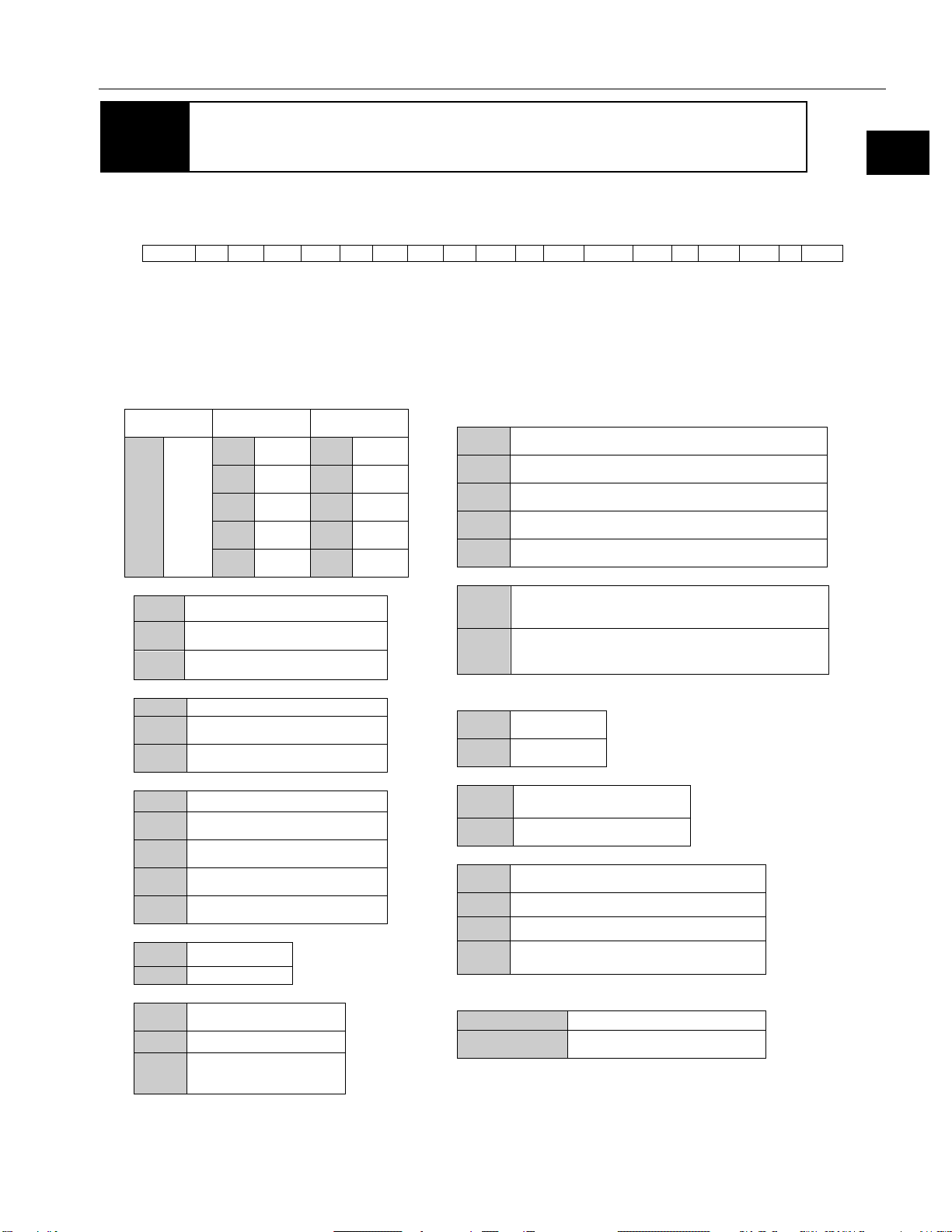
1-1 Overview
Outline
放熱板:350 *350*18
0
25
50
75
100
125
150
0 20 40 60 80 100 120
回転速度 [r/min]
トルク [Nm]
加減速運転領域
連続使用領域
50%デューティ領域
Allowable continuous torque
A
Radiation plate: 350*350*18
Torque [Nm]
Motion range during
accel
deceleration
50% duty range
Continuous
motion range
Rotation speed [rpm]
1 Overview of the SHA series
eration and
9
Page 10
1
2
3
4
5
6
7
8
9
10
11
付
Outline
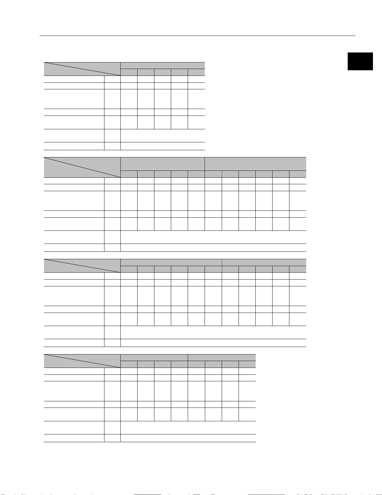
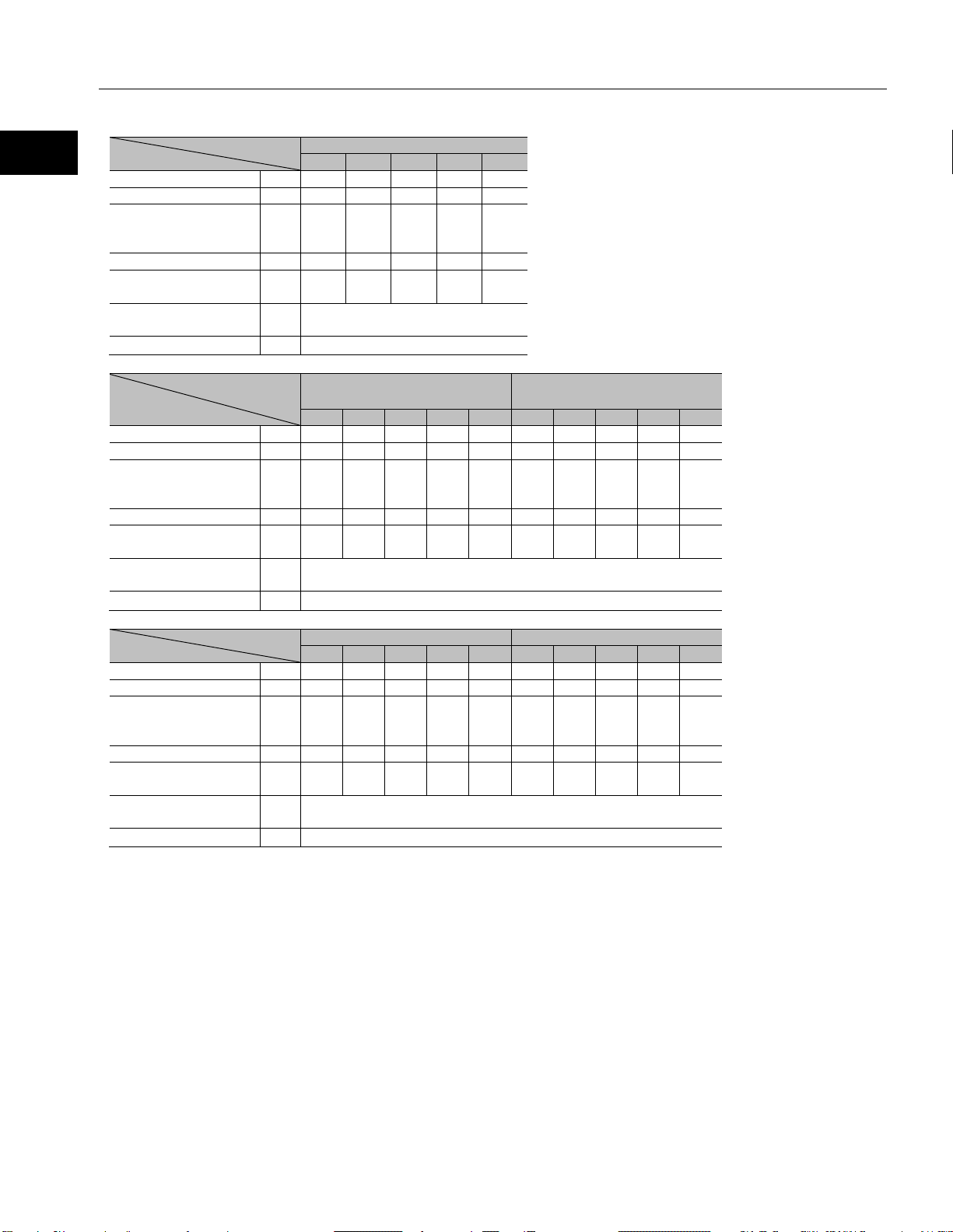
.
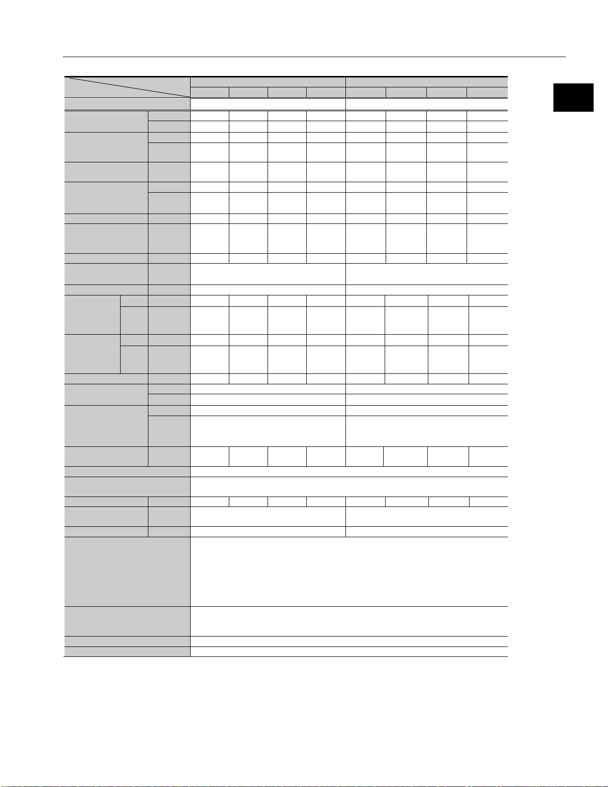
Model
Item
SHA20A
51
81
101
121
161
(1) Output at point A
W
99
109
109
106
86
(2) Voltage at point A
V
113
117
117
119
122
(3) Allowable
current
(4) Speed at point A
rpm
44
30
24
21
17
(5) Frequency at
point A
(6) Allowable range
temperature
(7) Number of phase
3
Model
SHA25A
(Motor input voltage 100V)
51
81
101
121
161
11
51
81
101
121
161
(1) Output at point A
W
165
188
190
178
127
133
175
203
207
178
127
(2) Voltage at point A
V
61
64
65
64
62
101
115
122
125
125
120
(3) Allowable
current
(4) Speed at point A
rpm
45
31
25
21
15
141
41
29
24.5
21
15
(5) Frequency at
point A
(6) Allowable range
temperature
(7) Number of phase
3
Model
Item
SHA32A
SHA40A
11
51
81
101
121
161
51
81
101
121
161
(1) Output at point A
W
240
328
369
373
308
233
487
564
570
560
480
(2) Voltage at point A
V
97
110
114
118
116
115
109
115
115
116
122
(3) Allowable
current
(4) Speed at point A
rpm
115
34
23
20
16.5
12.5
29
20.5
16.5
14
12
(5) Frequency at
point A
(6) Allowable range
temperature
(7) Number of phase
3
Model
Item
SHA58A
SHA65A
81
101
121
161
81
101
121
161
(1) Output at point A
W
897
948
863
731
964
963
958
802
(2) Voltage at point A
V
99
101
101
107
92
92
96
100
(3) Allowable
current
(4) Speed at point A
rpm
12
10
8.5
7.2
10 8 7.4
6.2
(5) Frequency at
point A
(6) Allowable range
temperature
(7) Number of phase
3
SG/HP type
1-1 Overview
Item
continuous
continuous
A
2.1 2.0 2.0 1.9 1.6
rms
Hz 187 203 202 212 228
℃ 40
-
SHA25A (Motor input voltage 200V)
A
4.7 4.7 4.7 4.5 3.7 3.0 3.0 3.0 2.9 2.6 2.1
rms
Hz 191 209 210 212 201 129 174 196 206 212 201
℃
-
40
continuous
A
6.0 6.0 6.0 5.7 5.0 4.1 9.0 9.0 9.0 8.8 7.2
rms
Hz 105 145 155 168 166 168 123 138 139 141 161
℃
-
40
continuous
A
17.7 17.8 16.4 13.4 22.0 21.9 20.1 16.3
rms
Hz 130 135 137 155 108 108 119 133
℃
-
40
10
Page 11
1-1 Overview
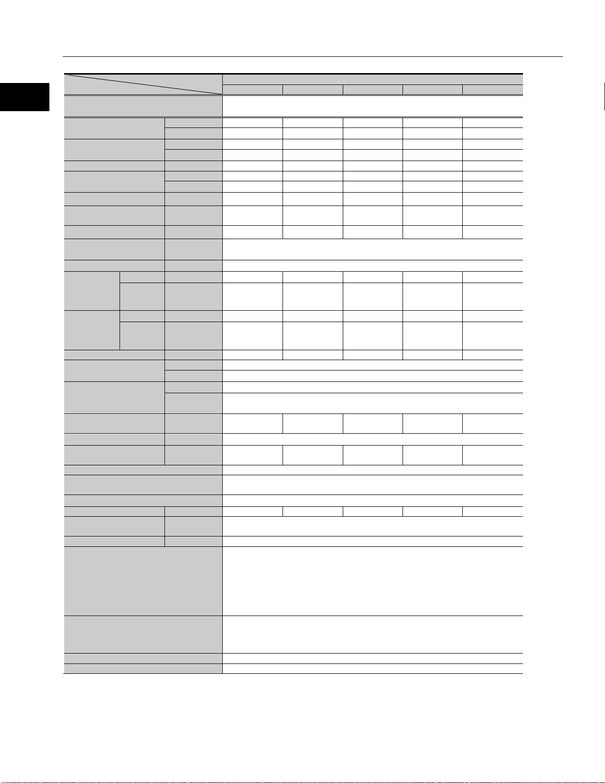
Outline
Model
Item
SHA20A
50
80
100
120
160
(1) Output at point A
W
97
108
108
106
85
(2) Voltage at point A
V
112
116
116
119
122
(3) Allowable
current
(4) Speed at point A
rpm
44
29.5
24
21
17
(5) Frequency at
point A
(6) Allowable range
temperature
(7) Number of phase
3
Model
SHA25A(Motor input voltage
100V)
SHA25A((Motor input
voltage 200V)
50
80
100
120
160
50
80
100
120
160
(1) Output at point A
W
167
191
192
174
127
177
201
204
174
127
(2) Voltage at point A
V
62
65
65
63
61
115
121
123
123
119
(3) Allowable
current
(4) Speed at point A
rpm
47
32
25.5
20.5
15
42
29
24
20.5
15
(5) Frequency at
point A
(6) Allowable range
temperature
(7) Number of phase
3
Model
Item
SHA32A
SHA40A
50
80
100
120
160
50
80
100
120
160
(1) Output at point A
W
321
372
373
308
233
493
558
568
568
488
(2) Voltage at point A
V
109
114
117
116
115
109
114
115
116
123
(3) Allowable
current
(4) Speed at point A
rpm
34
23.5
20
16.5
12.5
30
20.5
16.6
14.2
12.2
(5) Frequency at
point A
(6) Allowable range
temperature
(7) Number of phase
3
CG type
Item
continuous
continuous
A
2.1 2.1 2.1 2.0 1.7
rms
Hz 183 197 200 210 227
℃
-
A
4.7 4.7 4.7 4.5 3.7 3.0 3.0 3.0 2.6 2.1
rms
Hz 196 213 213 205 200 175 193 200 205 200
℃
-
40
40
continuous
A
6.0 6.0 5.7 5.0 4.1 9.0 9.0 9.0 8.8 7.2
rms
Hz 142 157 167 165 167 125 137 138 142 163
℃
-
40
11
Page 12

1
2
3
4
5
6
7
8
9
10
11
付
Outline
Chapter 1
Overview
This chapter explains the features, functions and specifications of the actuator.
1-1 Overview ············································································· 13
1-2 Model ················································································· 14
1-3 Drivers and extension cables ··················································· 15
1-4 Specifications ······································································· 16
1-5 Motor shaft brake ·································································· 25
1-6 External dimensions ······························································ 28
1-7 Mechanical accuracy ····························································· 40
1-8 Position al ac cur acy ······························································· 42
1-9
Encoder specifications (Absolute encoder)
1-10 Output Stiffness ································································· 46
1-11 Direction of rotation ····························································· 50
1-12 Shock resistance ································································ 51
1-13 Vibration resistance ···························································· 52
1-14 Operable range ·································································· 53
1-15 Cable specifications ···························································· 68
············································· 44
1-1 Overview
12
Page 13

1-1 Overview
Outline
1-1 Overview
The SHA series of AC Servo Actuators provide high torque and high accuracy rotary motion. These AC Servo Actuators are
each composed of a Harmonic Drive® speed reducer for precise control and a flat, high performance AC servo motor with an
integral absolute multi-turn encoder. The SHA series AC Servo Actuators all feature a large hollow shaft through the axis of
rotation.
There are 3 types of speed reducers: SG with SHG series incorporated, HP with HPF series incorporated, and CG with the
CSG series incorporated. They are an advanced version of current FHA series AC Servo Actuators having a flat, hollow
structure.
One key feature of the SHA actuators is their compact size. The outside diameter has been minimized, providing a maximum
torque/volume ratio which is approximately double that of conventional FHA actuators. A through hole is provided in the
center of the actuator, through which wiring, air lines, laser beams or concentric shafts may be passed.
The HA-800 series driver is a dedicated family of servo drive units for position/speed control, developed exclusively for driving
SHA series actuators. The small, multi-functional drivers control the SHA series actuators' operations with great accuracy and
precision. Additionally, the REL driver series may be used, which provides interface to many network field buses.
◆ Improved Torque Density
High-torque SHG or CSG series Harmonic Drive® speed reducers are incorporated into the actuator for precise control and
the outer diameter of the actuator has been reduced by 20% compared to our conventional products. As a result, the maximum
torque/volume ratio has approximately doubled compared to our previous actuator designs. Based on maximum torque, you
can select a model which is one size smaller. Also, the output torque is much higher than direct drive motors of similar
volume/weight. This is another reason why the SHA series has an outstanding performance advantage.
◆ Expanded product lineup
6 models are available for SG, accommodating high torque up to 3,400 Nm. The SHA line als o inc lud es m ode ls with reduction
ratios of 51 to 161. CG series has 4 fra me sizes available with 5 reduction ratios of 50:1 to 160:1.
◆ Modular design
The components of the SHA series, such as speed reducers, output shaft bearing, motor, brake and encoder, are arranged
based on a modular design. We can also custom-design a model to meet your specific requirements. Please contact your
HDLLC sales representative for details.
◆ Standar d 17-bit mag netic absolute encoder
The newly developed AC servo motors are equipped with our original, highly reliable 17-bit magnetic* absolute encoder with
safety functions. The serial communication reduces wiring and provides not only a multi-turn encoder, which is a must-have
feature on actuators with speed reducers, but it also has an internal backup to retain absolute positions even when the
encoder cable is disconnected for short periods of time.
The encoder circuitry also constantly compares two separate sets of encoder signals. If any abnormality is detected, the
encoder's built-in failsafe function outputs an alarm signal to the host system.
*SHA 20 comes with an optical encoder.
◆ Support for network control s
By using a dedicated HA-800 series driver, you can control your actuator on a MECHATROLINK-II or CC-Link network. The
REL series drivers support EtherCat, CANOpen, and Dev ice N et.
◆ For high speeds
Also supports high speeds in combination with the HPF hollow shaft planetary speed reducer.
13
Page 14
1
2
3
4
5
6
7
8
9
10
11
付
Outline
SHA
32 A 101
SG - B 12 A 200 -
10
S17b
A - C L -
SP
(1)
(2)
(3)
(4)
(5) -
(6)
(7)
(8)
(9) -
(10)
(11)
(12) -
(13)
(14) -
(15)
A
Size: 58, 65 (SG only)
08
Size: 20
B
With brake
(10) Encoder format
With standard connector
(for extension cables)
Output shaft single revolution absolute
model (CG only)
Blank
Standard product
1-2 Model
Model numbers for the SHA series actuators and how to interpret them are explained below.
Examples of standard models
(1) Model: SHA series actuator
(2) Size: SG: 20, 25, 32, 40, 58, 65
(3) Version: A: Standard, Y: Yaskawa compatible, M: Mitsubishi compatible, P: Panasonic compatible
(4) Reduction ratio (R:1)
Reduction ratio 11 is for the HPF hollow shaft planetary (Size 25, 32)
Reduction ratios 50 and higher are for the HarmonicDrive
(5) Gearhead
(6) Motor version symbol
(7) Motor size
(8) Brake
(9) Motor input voltage
:
CG: 20, 25, 32, 40
HP: 25, 32
HPF SHG CSG
51 51:1 50 50:1
81 81:1 80 80:1
11 11:1
HP HPF hollow shaft planetary
SG HarmonicDrive® SHG series
CG HarmonicDrive® CSG series
B Size: 25, 32, 40
C Size: 20
09 Size: 25
12 Size: 32
15 Size: 40
21 Size: 58, 65 (SG only)
A Without brake
100 100V (Size 25 only)
200 200V
LV
101 101:1 100 100:1
121 121:1 120 120:1
161 161:1 160 160:1
48V DC to 90V DC
(Size 20, 25,32)
®
gears
10 A-Format (2.5Mbps, 1 to 1 connection)
00 Incremental Encoder
14 Panasonic Format
16 Mitsubishi Format (not available in size 20)
17 Yaskawa Format (not available in size 20)
(11) Encoder type, resolution
S17b
D250 D250: Incremental encoder (size 25, 32, and 40)
(12) Encoder phase angle: Phase difference between
induced voltage in motor phase U and absolute origin
A 0 degree
B 30 Dgree
(13) Connector specification
C
N With Pigtails
(14) Option symbol
L With near origin and end limit sensors
Y Side exiting cable
V With mounting stand (CG only)
S
(Please contact us for option-compatible models.)
(15) Special specification
SP____ Special specification code
17-bit absolute encoder, 131,072
pulses/revolution (Nikon-A format)
1-2 Model
14
Page 15

1-3 Drivers and extension cables
Outline
HA-800A-6 D/E -
200
HA-800B-6D/E -
200
HA-800C-6D/E -
200
HA-800□-6D/E:
TMC
Encoder
cable
1-3 Drivers and ext ension cables
The proper combination of SHA actuators, drivers, and extension cables are as follows:
SHA20A SHA25A SHA32A SHA40A SHA58A SHA65A
REL Servo Drive
HA-800 Standard
I/O command type
REL-230-18 REL-230-18
HA-800A-
HA-800A-
3D/E -200
3D/E-200
(HA-800A-
6D/E -100)
REL230-36
REL 230-40
HA-800A6D/E -200
200
or
HA-800A-24D/E -
HA-800A-
24D/E -200
HA-800A-
24D/E -
200
HA-800
MECHATROLINK
HA-800 CC-Link
Extension
cables
(option)
Motor
cable
HA-800B-
3D/E -200
HA-800C3D/E -200
HA-800B3D/E -200
(HA-800B-
6D/E -100)
HA-800C3D/E -200
(HA-800C-
6D/E -100)
EWD-MB**-A06-TN3
(Driver side connector
supplied separately)
EWD-S**-A08-3M14 EWD-S**-D10-3M14
HA-800B6D/E -200
HA-800C6D/E -200
200
or
HA-800B-24D/E -
200
or
HA-800C-24D/E -
EWD-MB**-A06-
TN3
HA-800□-24D/E:
EWD-MB**-A06-
HA-800B-
24D/E -200
HA-800C-
24D/E -200
EWD-MB**-D09-TMC
** in the extension cable model indicates the cable length: 03 = 3m, 05 = 5m, 10 = 10m
The models shown in parenthesis are those with 100V motor input voltage combinations.
HA-800B-
24D/E -
200
HA-800C-
24D/E -
200
15
Page 16
1
2
3
4
5
6
7
8
9
10
11
付
Outline
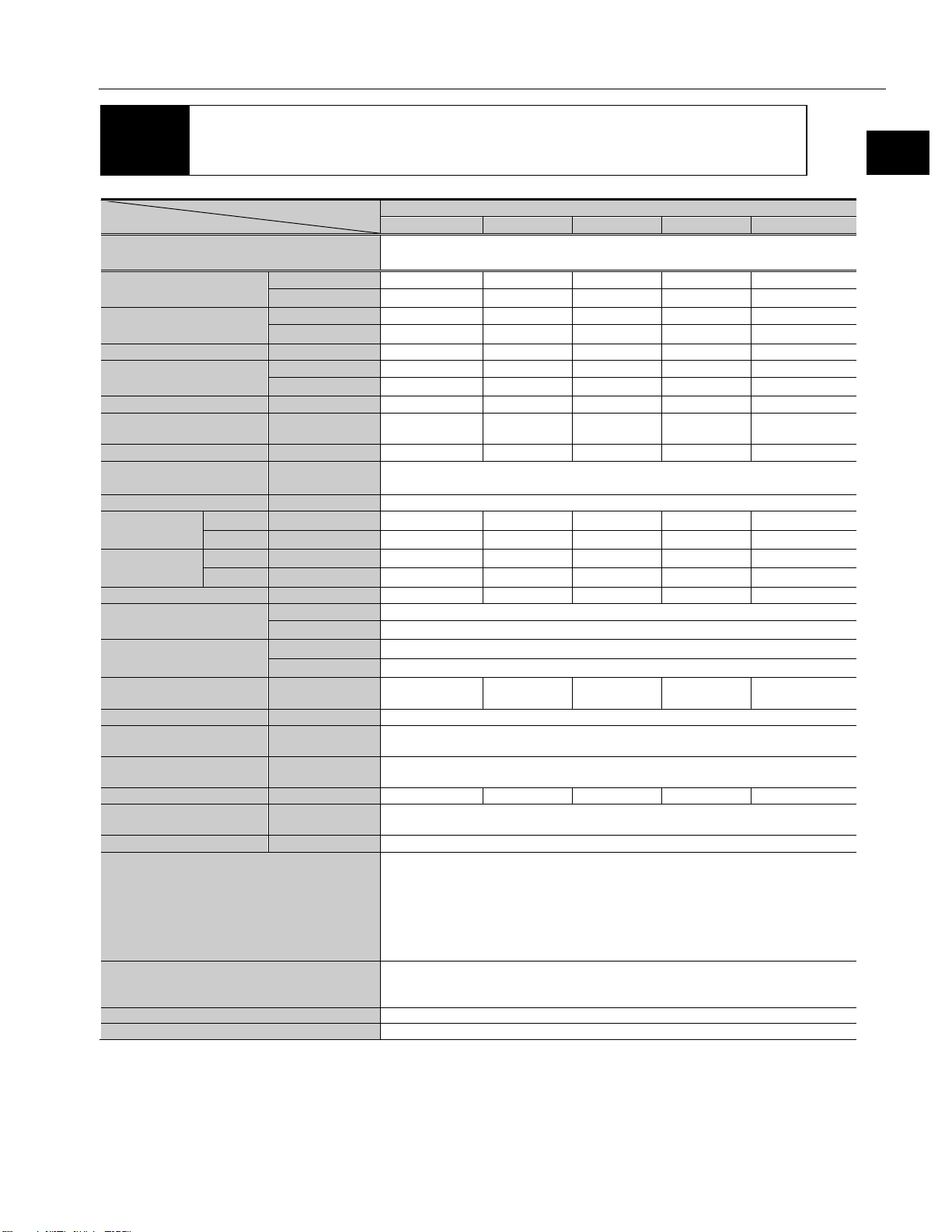
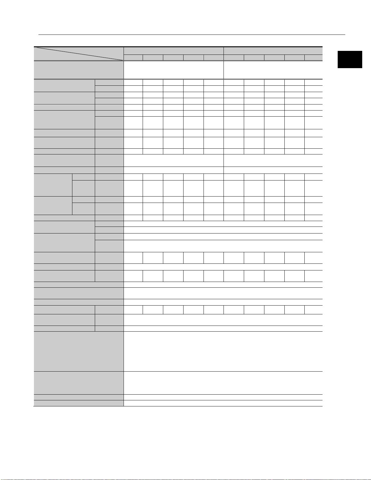
Model
Item
SHA20A
51
81
101
121
161
REL-230-18
HA-800□-3D/E-200
Nm
73
96
107
113
120
kgf・m
7.4
9.8
10.9
11.5
12.2
Allowable continuous
torque
Nm
21
35
43
48
48
kgf・m
2.1
3.6
4.4
4.9
4.9
Max. rotational speed*1
rpm
117.6
74.1
59.4
49.6
37.3
Nm/A
16.5
27
33
40
53
kgf・m/A
1.7
2.7
3.4
4.1
5.4
Max. current*1
A
rms
6.0
4.9
4.5
4.0
3.4
Allowable continuous
current
EMF constant*3
V/(rpm)
1.9
3.0
3.7
4.5
5.9
Phase resistance
(20℃)
Ω
Phase inductance
mH
2.5
(without brake)
GD2/4
kg・m2
0.23
0.58
0.91
1.3
2.3
J
kgf・cm・s2
2.4
6.0
9.3
13
24
GD2/4
kg・m2
0.26
0.65
1.0
1.4
2.6
J
kgf・cm・s2
2.6
6.6
10
15
26
Reduction ratio
51:1
81:1
101:1
121:1
161:1
moment load
Nm
187
kgf・m
19.1
Nm/rad
25.2×10⁴
kgf・m/arc min
7.5
One-way positional
accuracy
Encoder type
Absolute encoder
Single motor revolution
Encoder resolution
Motor multi revolution
counter
Output resolution
Pulse/rev
6,684,672
10,616,832
13,238,272
15,859,712
21,102,592
Mass
(without brake)
Mass (with brake)
kg
2.1
Environmental conditions
Operating temper ature: 0 to 40℃/Storage temperature: -20 to 60℃
Altitude: les s than 1,000 m above sea level
Motor insulation
Insulation resistance: 100MΩ or more (by DC500V insulation tester)
Insulation cl ass: A
Mounting direction
Can be installed in any di rection.
Protection structure
Totally enclosed self-cooled type (IP54)
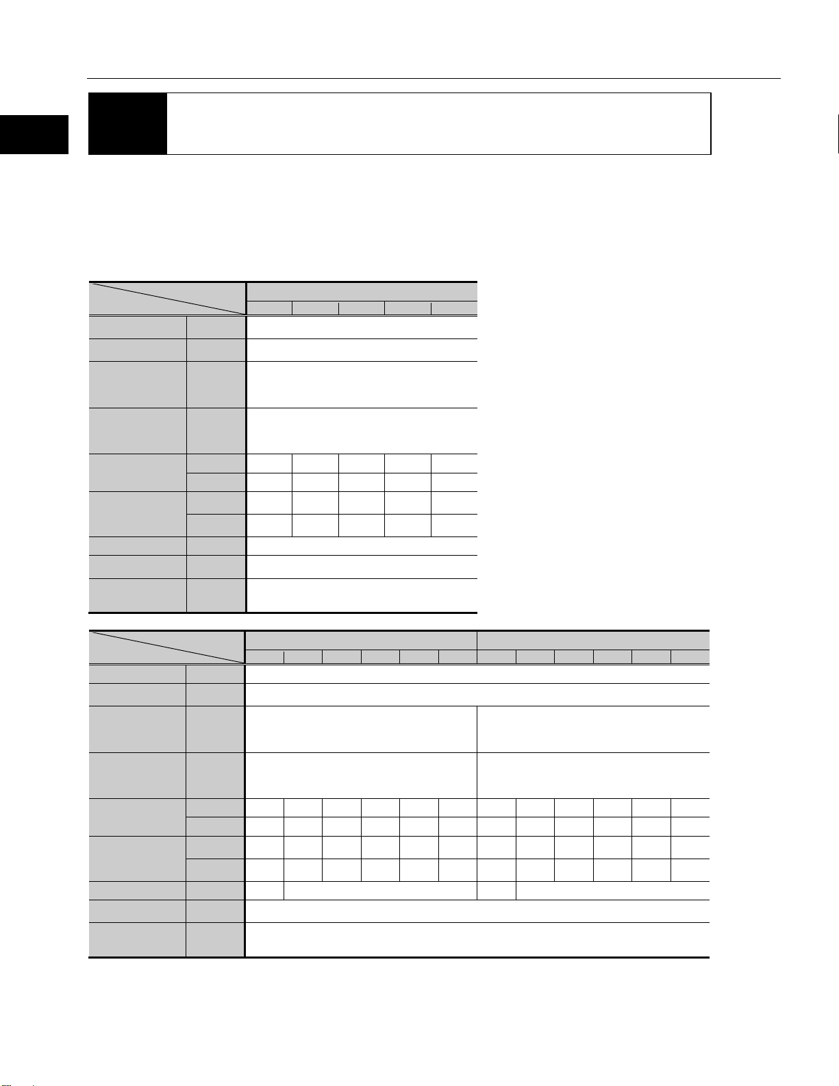
1-4 Specifications
SG type
Servo Drive
Max. torque*1
*1*2
Torque constant*1
A
2.1 2.0 2.0 1.9 1.6
*1*2
rms
1-4 Specifications
Inertia moment
Inertia moment
(with brake)
Moment stiffness
Permissible
arc-sec
kg 2.0
60 50 50 50 50
Operating humidity/storage humidity: 20 to 80%RH (no condensation)
Resistance to vibr ation: 25 m/s
300 m/s
No dust, no metal powder, no corrosive gas, no inflammable gas , no oil mist
To be used indoors, no direct sunlight
2 *4
1.4
217(131,072)
216(65,536)
2
(frequenc y: 10 to 400Hz)/Shock resistance:
Dielectric strength: AC1,500V/1 min
The table shows typical output values of actuators.
*1: Typical characteristics when combined (driven by ideal sine wave) with our drivers.
*2: Value after temperature rise and saturation when the 320 x 320 x 16 [mm] aluminum radiation plate is installed.
*3: Value of phase induced voltage constant multiplied by 3.
*4: For testing conditions, refer to [1-12 Shock resistance] (P51) and [1-13 Vibration resistance ] (P52).
16
Page 17
1-4 Specifications
Outline
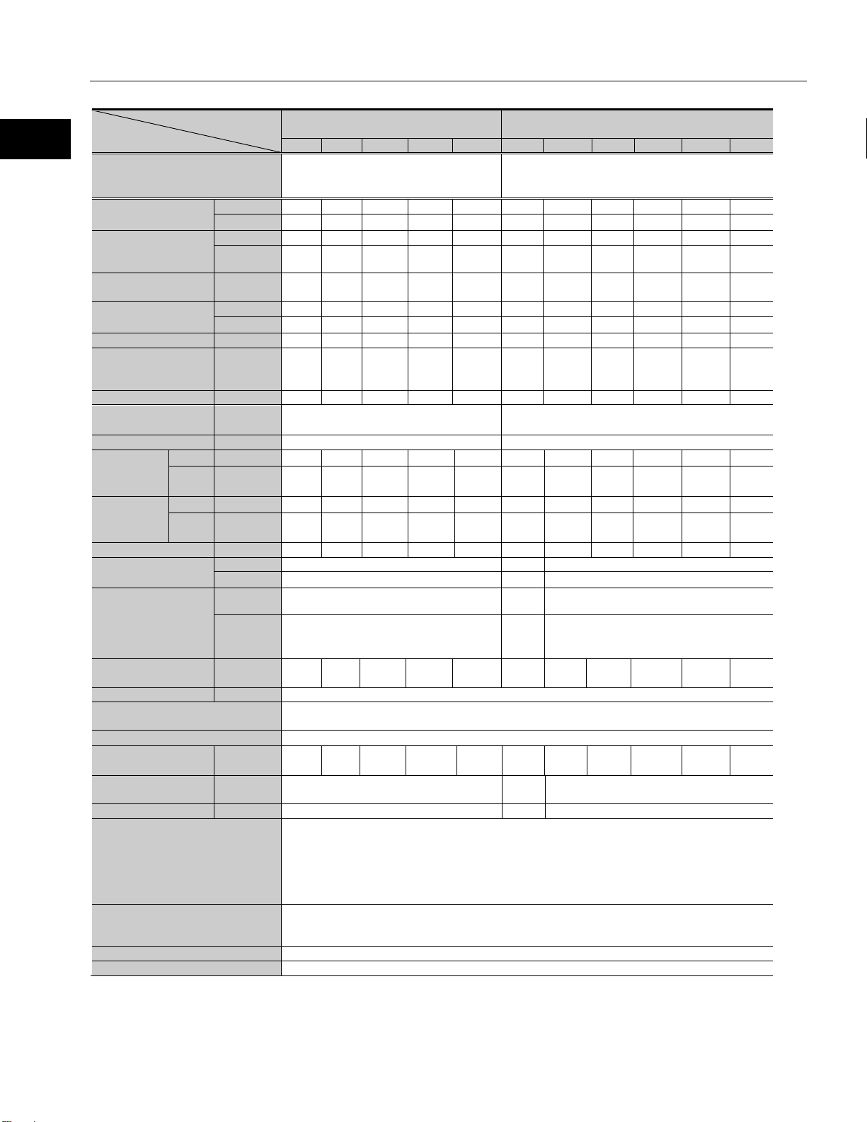
SHA25A
(Motor input voltage 100V)
51
81
101
121
161
11
51
81
101
121
161
REL-230-18
HA-800□-3D/E-200
Nm
127
178
204
217
229
26
127
178
204
217
229
kgf・m
13
18.2
20.8
22.1
23.4
2.7
13
18.2
20.8
22.1
23.4
Allowable
torque
Nm
35
58
73
81
81
9.0
41
67
81
81
81
Max. rotational
speed*1
Nm/A
rms
11.1
17.9
22
27
36
4.2
19
31
39
46
62
kgf・m/A
1.1
1.8
2.3
2.7
3.6
0.43
2.0
3.2
4.0
4.7
6.3
Max. current*1
A
rms
14.9
13.0
12.1
10.9
9.0
8.9
8.6
7.5
7.0
6.3
5.2
Allowable
current
EMF constant*3
V/(rpm)
1.3
2.0
2.5
3.0
4.0
0.47
2.2
3.5
4.3
5.2
6.9
Phase resistance
(20℃)
Phase inductance
mH
1.0
3
GD2/4
kg・m2
0.56
1.4
2.2
3.2
5.6
0.029
0.56
1.4
2.2
3.2
5.6
kgf・cm・
s2
GD2/4
kg・m2
0.66
1.7
2.6
3.7
6.6
0.034
0.66
1.7
2.6
3.7
6.6
kgf・cm・
s2
Reduction ratio
1:51
1:81
1:101
1:121
1:161
1:11
1:51
1:81
1:101
1:121
1:161
Permissible
moment load
Nm
258
410
258
kgf・m
26.3
41.8
26.3
37.9
x 104
kgf・
min
One-way positional
accuracy
Encoder type
Magnetic absol ute encoder
Single motor revolution
Encoder resolution
Motor multi revolution counter
2
16
65,536)
10,61
832
Mass
(without brake)
Mass (with brake)
kg
3.1
5.1
3.1
Environmental conditions
Operating temper ature: 0 to 40℃/Storage temperature: -20 to 60℃
Altitude: les s than 1,000 m above sea level
Motor insulation
Insulation resistance: 100MΩ or more (by DC500V insulation tester)
Insulation cl ass: A
Mounting direction
Can be installed in any direction.
Protection structure
Totally enclosed self-cooled type (IP54)
SG/HP type
Item
Model
SHA25A (Motor input voltage 200V)
Servo Drive
Max. torque*1
continuous
*1*2
Torque constant*1
continuous
*1*2
Inertia moment
(without brake)
Inertia moment
(with brake)
REL-230-18
HA-800□-6D/E-100
kgf・m
rpm
A
rms
Ω
J
J
3.6 5.9 7.4 8.2 8.2 0.92 4.2 6.8 8.2 8.2 8.2
94.1 59.3 47.5 39.7 29.8 509.1 109.8 69.1 55.4 46.3 34.8
4.7 4.7 4.7 4.5 3.7 3.0 3.0 3.0 2.9 2.6 2.1
0.4 1.2
5.7 14 22 32 57 0.30 5.7 14 22 32 57
6.7 17 26 38 67 0.35 6.7 17 26 38 67
REL-230-36
Nm/rad
Moment stiffness
m/arc
50 40 40 40 40 120 50 40 40 40 40
6,684,
672
6,
Output resolution
arc-sec
Pulse/rev
kg
Operating humidity/storage humidity: 20 to 80%RH (no condensation)
Resistance to vibration: 25 m/s
No dust, no metal powder, no corrosive gas, no inflammable gas , no oil mist
To be used indoors, no direct sunlight
Dielectric strength: AC1,500V/1 min
The table shows typical output values of actuators.
*1: When combined with a HA-800 driver.
*2: Value after temperature rise and saturation when the 350 x 350 x 18 [mm] aluminum radiation plate is installed.
*3: Value of phase induced voltage constant multiplied by 3.
*4: For testing conditio ns, ref er to [1-12 Shock resistance] (P51) and [1-13 Vibration resistance ] (P52).
17
39.2 x 10⁴
11.6 11.3 11.6
217(131,072)
(
13,238,
272
15,859,
712
21,102,
592
1,441,
792
6,684,
672
10,616,
832
2.95 5.0 2.95
2
(
frequency: 10 to 400Hz
)/Shock r esistance: 300 m/s
39.2 x 10⁴
13,238,
272
15,859,
712
2 *4
21,102,
592
Page 18
1
2
3
4
5
6
7
8
9
10
11
付
Outline
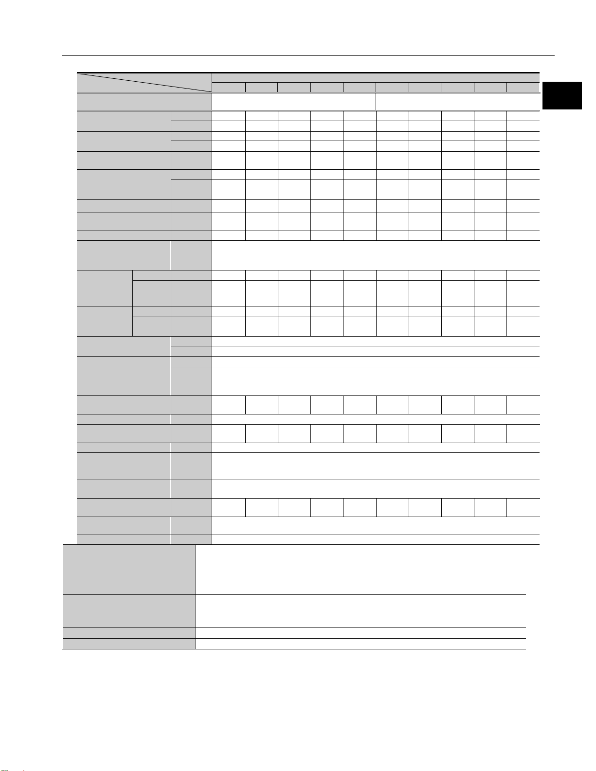
SG/HP type
Model
Item
SHA32A
11
51
81
101
121
161
Nm
62
281
395
433
459
484
kgf・m
6.3
28.7
40.3
44.2
46.8
49.4
Allowable
torque
Nm
20
92
153
178
178
178
Max. rotational
speed*1
Nm/A
rms
4.5
21
33
42
50
66
kgf
・
m/A
rms
Max. current*1
A
rms
19
17.3
15.2
13.5
12.2
9.9
Allowable
current
EMF constant*3
V/(rpm)
0.51
2.3
3.7
4.7
5.6
7.4
Phase resistance
(20℃)
Phase inductance
mH
1.4
Inertia
brake)
GD2/4
kg・m2
0.091
2.0
5.1
8.0
11
20
・
Inertia
brake)
GD2/4
kg・m2
0.11
2.3
5.9
9.2
13
23
・
Reduction ratio
1:11
1:51
1:81
1:101
1:121
1:161
Permissible
moment load
Nm
932
580
kgf・m
95
59.1
Nm/rad
86.1 x 10⁴
100 x 104
kgf・
min
Encoder type
Magnetic absol ute encoder
Single motor
Encoder resolution
Motor multi
revolution counter
Output resolution
Pulse/rev
1,441,792
6,684,672
10,616,832
13,238,272
15,859,712
21,102,592
Mass
(without brake)
Mass (with brake)
kg
9.7
6.2
Environmental conditions
Operating temperature: 0 to 40℃/Storage temperature: -20 to 60℃
Altitude: less than 1,000 m above sea level
Motor insulation
Insulation resistance: 100MΩ or more (by DC500V insulation tester)
Insulation class: A
Mounting direction
Can be installed in any direction.
Protection structure
Totally enclosed self-cooled type (IP54)
1-4 Specifications
Servo Drive
Max. torque*1
continuous
Torque constant*1
continuous
moment
(without
moment
(with
*1*2
*1*2
J
J
REL-230-18, REL-230-36
HA-800□-6D/E-200
kgf・m
rpm 436.4 94.1 59.3 47.5 39.7 29.8
A
6.0 6.0 6.0 5.7 5.0 4.1
rms
Ω 0.33
kgf
cm・s2
kgf
cm・s2
2.1 9.4 15.6 18.2 18.2 18.2
0.46 2.1 3.4 4.2 5.1 6.8
0.93 21 52 81 117 207
1.1 24 60 94 135 238
Moment stiffness
One-way positional
accuracy
revolution
m/arc
arc-sec 120 50 40 40 40 40
217(131,072)
216(65,536)
kg 9.4 5.9
25.7 29.6
Operating humidity/storage humidity: 20 to 80%RH (no cond en sation)
Resistance to vibration: 25 m/s
No dust, no metal powder, no corrosive gas, no inflammable gas, no oil mist
To be used indoors, no direct sunlight
Dielectric strength: AC1,500V/1 min
The table shows typical output values of actuators.
*1: When combined with a HA-800 driver.
*2: Value after temperature rise and saturation when the 400 x 400 x 20 [mm] aluminum radiation plate is installed.
*3: Value of phase induced voltage constant multiplied by 3.
*4: For testing conditio ns, ref er to [1-12 Shock resistance] (P51) and [1-13 Vibration resistance ] (P 52).
2
(frequency: 10 to 400Hz)/Shock resistanc e: 300 m/s
2 *4
18
Page 19
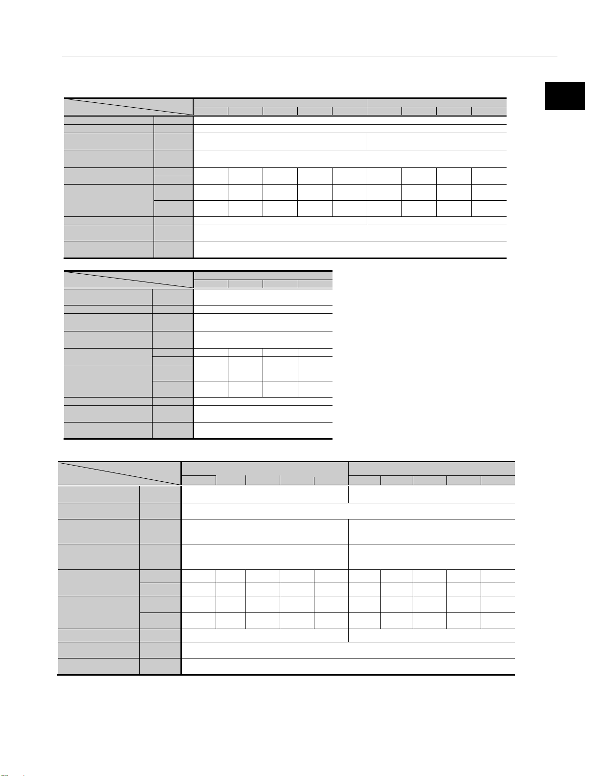
1-4 Specifications
Outline
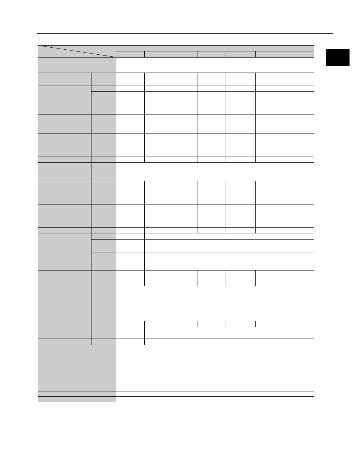
Model
Item
SHA40A
51
81
101
121
161
51
81
101
121
161
Nm
340
560
686
802
841
523
675
738
802
841
kgf・m
34.7
57.1
70
81.8
85.8
53.4
68.9
75.3
81.8
85.8
Allowable continuous
torque
Nm
94
158
198
237
317
160
263
330
382
382
kgf・m
9.6
16.1
20.2
24.2
32.3
16.3
26.8
33.7
39
39
Max. rotational speed*2
rpm
78.4
49.4
39.6
33.1
24.8
78.4
49.4
39.6
33.1
24.8
Nm/A
rms
25
41
51
61
81
25
41
51
61
81
kgf
・
m/A
rms
Max. current*2
A
rms
18
18
18
17.9
14.6
26.7
21.8
19.4
17.9
14.6
Allowable continuous
current
EMF constant*4
V/(rpm)
2.9
4.6
5.7
6.8
9.1
2.9
4.6
5.7
6.8
9.1
Phase resistance
(20℃)
Phase inductance
mH
1.2
GD2/4
kg・m2
5.0
13
20
28
50
5.0
13
20
28
50
kgf・cm・
s2
GD2/4
kg・m2
6.1
15
24
34
61
6.1
15
24
34
61
kgf・cm・
s2
Reduction ratio
1:51
1:81
1:101
1:121
1:161
1:51
1:81
1:101
1:121
1:161
Permissible
moment load
Nm
849
kgf・m
86.6
Nm/rad
179 x 104
kgf・
min
One-way positional
accuracy
Encoder type
Magnetic absol ute encoder
Single motor revolution
Encoder resolution
Motor multi revolution counter
2
16
65,536)
Mass
(without brake)
Mass (with brake)
kg
10.7
Environmental conditions
Operating temper ature: 0 to 40℃/Storage temperature: -20 to 60℃
Altitude: les s than 1,000 m above sea level
Motor insulation
Insulation resistance: 100MΩ or more ( by D C 500V insulation tester)
Insulation cl ass: A
Mounting direction
Can be installed in any di rection.
Protection structure
Totally enclosed self-cooled type (IP54)
SG type
Servo Drive HA-800□-6D/E-200*1
Max. torque*2
*2*3
Torque constant*2
*2*3
Inertia moment
(without brake)
Inertia moment
(with brake)
REL-230-36, REL-230-40
HA-800□-24D/E-200
2.6 4.1 5.2 6.2 8.2 2.6 4.1 5.2 6.2 8.2
A
6.0 6.0 6.0 6.0 6.0 9.0 9.0 9.0 8.8 7.2
rms
Ω 0.19
J
J
51 130 202 290 513 51 130 202 290 513
62 157 244 350 619 62 157 244 350 619
Moment stiffness
m/arc
53.2
arc-sec 50 40 40 40 40 50 40 40 40 40
217(131,072)
(
Output resolution
Pulse/rev
6,684,
672
10,616,
832
13,238,
272
15,859,
712
21,102,
592
6,684,
672
10,616,
832
13,238
,272
15,859,
712
21,102,
592
kg 9.9
Operating humidity/storage humidity: 20 to 80%RH (no condensati on)
Resistance to vibration: 25 m/s
2
(
frequency: 10 to 400Hz
)/Shock r esistance: 300 m/s
2 *5
No dust, no metal powder, no corrosive gas, no inflammable gas , no oil mist
To be used indoors, no direct sunlight
Dielectric strength: AC1,500V/1 min
The table shows typical output values of actuators.
*1: If a HA-800□-6D/E driver is combined with a SHA40A actuator, the maximum torque and allowable continuous torque are limited.
*2:
When combined with HA-800 driver.
*3: Value after temperature rise and saturation when the 500 x 500 x 25 [mm] aluminum radiation plate is installed.
*4: Value of phase induced voltage constant multiplied by 3.
*5: For testing conditio ns, ref er to [1-12 Shock resistance] (P51) and [1-13 Vibration resistance ] (P 52).
19
Page 20
1
2
3
4
5
6
7
8
9
10
11
付
Outline
SG type
Model
Item
SHA58A
SHA65A
81
101
121
161
81
101
121
161
Servo Drive
HA-800□-24D/E-200
HA-800□-24D/E-200
Nm
1924
2067
2236
2392
2400
2990
3263
3419
kgf・m
196
211
228
244
245
305
333
349
Allowable
torque
Nm
714
905
969
969
921
1149
1236
1236
Max. rotational
speed*1
Nm/A
rms
54
68
81
108
54
68
81
108
kgf
・
m/A
rms
Max. current*1
A
rms
45
39
36
30
55
55
51
41
Allowable
current
EMF constant*3
V/(rpm)
6.1
7.6
9.1
12.1
6.1
7.6
9.1
12.1
Phase resistance
(20℃)
Phase inductance
mH
0.29
0.29
Inertia
brake)
GD2/4
kg・m2
96
149
214
379
110
171
245
433
・
Inertia
brake)
GD2/4
kg・m2
106
165
237
420
120
187
268
475
・
Reduction ratio
1:81
1:101
1:121
1:161
1:81
1:101
1:121
1:161
Permissible
moment load
Nm
2180
2740
kgf・m
222
280
Nm/rad
531 x 104
741 x 104
kgf・
min
One-way positional
accuracy
Encoder type
Magnetic absol ute encoder
Single motor revolution
Encoder resolution
Output resolution
Pulse/rev
Mass
(without brake)
Mass (with brake)
kg
32
40
Environmental conditions
Operating temper ature: 0 to 40℃/Storage temperature: -20 to 60℃
Altitude: les s than 1,000 m above sea level
Motor insulation
Insulation resistance: 100MΩ or more (by DC500V insulation tester)
Insulation cl ass: A
Mounting direction
Can be installed in any di rection.
Protection structure
Totally enclosed self-cooled type (IP54)
Max. torque*1
1-4 Specifications
continuous
Torque constant*1
continuous
moment
(without
moment
(with
Moment stiffness
*1*2
*1*2
J
J
kgf・m 73 92 99 99 94 117 126 126
rpm
A
rms
Ω
kgf
cm・s2
kgf
cm・s2
m/arc
37.0 29.7 24.8 18.6 34.6 27.7 23.1 17.4
5.5 6.9 8.3 11.0 5.5 6.9 8.3 11.0
17.7 17.8 16.4 13.4 22.0 21.9 20.1 16.3
0.028 0.028
980 1520 2180 3870 1120 1740 2500 4420
1090 1690 2420 4290 1230 1910 2740 4850
158 220
arc-sec
kg
The table shows typical output values of actuators.
*1: When combined with HA-8 00 driver.
*2: Value after temperature rise and saturation when the 650 x 650 x 30 [mm] aluminum radiation plate is installed.
*3: Value of phase induced voltage constant multiplied by 3.
*4: For testing conditio ns, ref er to [1-12 Shock resistance] (P51) and [1-13 Vibration resistance ] (P 52).
40 40 40 40 40 40 40 40
10,616,832 13,238,272 15,859,712 21,102,592 10,616,832 13,238,272 15,859,712 21,102,592
Operating humidity/storage humidity: 20 to 80%RH (no condensati on)
Resistance to vibr ation: 25 m/s
2 *4
m/s
No dust, no metal powder, no corrosive gas, no inflammable gas , no oil mist
To be used indoors, no direct sunlight
Dielectric strength: AC1,500V/1 min
217(131,072)
29.5 37.5
2
(frequency: 10 to 400Hz)/Shock res istance: 300
20
Page 21
1-4 Specifications
Outline
Actuator Model
Item
SHA20A
50
80
100
120
160
REL-230-18
HA-800□-3D/E-200
Nm
73
96
107
113
120
kgf・m
7.4
9.8
10.9
11.5
12.2
Allowable continuous
torque
Nm
21
35
43
48
48
kgf・m
2.1
3.6
4.4
4.9
4.9
Max. rotational speed*1
rpm
120
75
60
50
37.5
Nm/A
rms
16
26
33
39
53
kgf・m/A
rms
1.7
2.7
3.4
4.0
5.4
Max. current*1
A
rms
6.1
5.0
4.6
4.1
3.4
Allowable continuous
current
EMF constant*3
V/(rpm)
Phase resistance
(20℃)
Ω
Phase inductance
mH
2.5
Inertia
brake)
GD2/4
kg・m2
0.21
0.53
0.82
1.2
2.1
Inertia
brake)
GD2/4
kg・m2
0.23
0.60
0.94
1.3
2.4
Reduction ratio
1:50
1:80
1:100
1:120
1:160
Permissible moment
load
Nm
187
kgf・m
19.1
Nm/rad
25.2×10⁴
kgf・m/arc
min
One-way positional
accuracy
Repeatability
arc-sec
5
Bi-directional
repeatability
Encoder type
Magnetic absolut e encoder
Single motor revolution
Encoder resolution
Motor multi revolution counter
2
16
65,536)
Output resolution
Pulse/rev
6,553,600
10,485,760
13,107200
15,728,640
20,971,520
Mass
(without brake)
Mass (with brake)
kg
2.7
Environmental conditions
Operating temper ature: 0 to 40℃/Storage temperature: -20 to 60℃
Altitude: les s than 1,000 m above sea level
Motor insulation
Mounting direction
Can be installed in any di rection
Protection structure
Totally enclosed self-cooled type (IP54)
CG type
Servo Drive
Max. torque*1
*1*2
Torque constant*1
*1*2
moment
(without
moment
(with
A
2.1 2.1 2.1 2.0 1.7
rms
1.8 2.9 3.7 4.4 5.9
1.4
J kgf・cm・s2 2.1 5.4 8.0 12 22
J kgf・cm・s2 2.4 6.1 9.6 14 24
Moment stiffness
arc-sec 60 50 50 50 50
arc-sec 75 30 30 30 30
kg 2.6
Operating humidity/storage humidity: 20 to 80%RH (no condensati on)
Resistance to vibrat ion: 25 m/s
300 m/s
No dust, no metal powder, no corrosive gas, no inflammable gas, no oil mist
To be used indoors, no direct sunlight
Insulation resistance: 100MΩ or more (by DC500V insulation tester)
Dielectric strength: AC1,500V/1 min
Insulation cl ass: A
The table shows typical output values of actuators.
*1: Typical characteristics when combined with our HA-800 driver.
*2: Value after temperature rise and saturation when the 350 x 350 x 18 [mm] aluminum radiation plate is installed.
*3: Value of phase induced voltage constant multiplied by 3.
*4: For testing conditions, refer to [1-12 Shock resistance] (P51) and [1-13 Vibration resistance ] (P52).
21
2 *4
7.5
±
217(131,072)
(
2
(frequency: 10 to 400H z)/Shock resistance:
Page 22
1
2
3
4
5
6
7
8
9
10
11
付
Outline
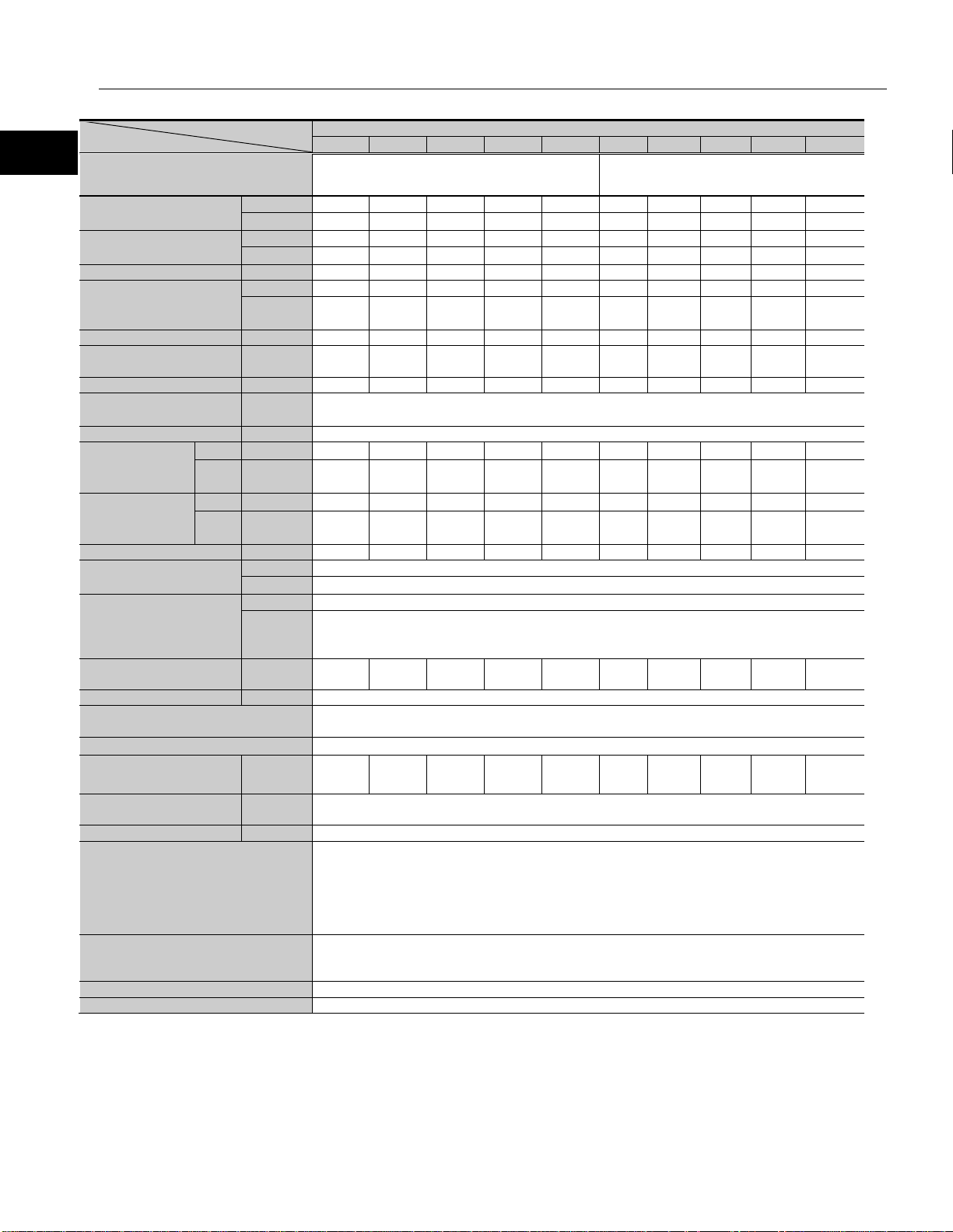
CG type
Item
SHA25A(Motor input voltage 100V)
SHA25A(Motor input voltage 200V)
50
80
100
120
160
50
80
100
120
160
REL-230-18
HA-800□-6D/E-100*1
REL-230-18
HA-800□-3D/E-200
Nm
127
178
204
217
229
127
178
204
217
229
kgf・m
13
18.2
20.8
22.1
23.4
13
18.2
20.8
22.1
23.4
Allowable continuous
torque
Nm
34
57
72
81
81
40
66
81
81
81
kgf・m
3.5
5.8
7.3
8.2
8.2
4.1
6.8
8.2
8.2
8.2
Max. rotational speed*1
rpm
96
60
48
40
30
112
70
56
46.7
35
Nm/A
rms
10.9
17.7
22
27
35
19
31
38
46
61
kgf・
m/A
rms
Allowable continuous
current
EMF constant*3
V/(rpm)
1.2
2.0
2.5
3.0
4.0
2.1
3.4
4.3
5.2
6.9
Phase resistance
(20℃)
Ω
Phase inductance
mH
1.0
3.0
Inertia
brake)
GD2/4
kg・m2
0.50
1.3
2.0
2.9
5.1
0.50
1.3
2.0
2.9
5.1
・
Inertia
(with brake)
GD2/4
kg・m2
0.60
1.5
2.4
3.4
6.1
0.60
1.5
2.4
3.4
6.1
kgf・cm・
s2
Reduction ratio
mH
50:1
80:1
120:1
1:120
160:1
50:1
80:1
120:1
1:120
160:1
Nm
258
kgf・m
26.3
Nm/rad
39.2×10⁴
kgf・m/arc
min
One-way positional
accuracy
Repeatability
arc-sec
5
Bi-directional positional
accuracy
Encoder type
Magnetic absolute encoder
Single motor revolution
Encoder resolution
Motor multi revolution counter
2
16
65,536)
6,553,
600
10,485,
760
13,107,
200
15,728,
640
20,971,
520
6,553,
600
10,485,
760
13,107,
200
15,728,
640
20,971,
520
Mass
(without brake)
Mass (with brake)
kg
4.1
Environmental conditions
Motor insulation
Mounting direction
Can be installed in any direction
Protection structure
Totally enclosed self-cooled type (IP54)
1-4 Specifications
Model
Servo Drive
Max. torque*1
*1*2
Torque constant*1
Max. current*1
*1*2
moment
(without
moment
Permissible moment load
Moment stiffness
J
J
REL-230-36
1.1 1.8 2.3 2.7 3.6 1.9 3.1 3.9 4.7 6.3
A
rms
A
rms
kgf・cm
s2
15.1 13.2 12.2 11.0 9.0 8.7 7.6 7.0 6.3 5.2
4.7 4.7 4.7 4.5 3.7 3.0 3.0 3.0 2.6 2.1
0.4 1.2
5.1 13 20 29 52 5.1 13 20 29 52
6.1 16 24 35 62 6.1 16 24 35 62
11.6
REL-230-36
arc-sec
arc-sec
Output resolution
Pulse/rev
kg 3.95
The table shows typical output values of actuators.
*1: Typical characteristics when combined (driven by ideal sine wave) with our drivers.
*2: Value after temperature rise and saturation when the 350 x 350 x 18 [mm] aluminum radiation plate is installed.
*3: Value of phase induced voltage constant multiplied by 3.
*4: For testing conditions, refer to [1-12 Shock resistance] (P51) and [1-13 Vibration resistance ] (P52).
50 40 40 40 40 50 40 40 40 40
±
60 25 25 25 25 60 25 25 25 25
217(131,072)
(
Operating temperature: 0 to 40℃/Storage temperature: -20 to 60℃
Operating humidity/storage humidity: 20 to 80%RH (no condensation)
Resistance to vibration: 25 m/s
No dust, no metal powder, no corrosive gas, no inflammable gas, no oil mist
To be used indoors, no direct sunlight
Altitude: less than 1,000 m above sea level
Insulation resistance: 100MΩ or more (by DC500V insulation tester)
Dielectric strength: AC1,500V/1 min
Insulation class: A
2
(frequency: 10 to 400Hz)/Shock resistance: 300 m/s
2 *4
22
Page 23

1-4 Specifications
Outline
Model
Item
SHA32A
50
80
100
120
160
REL-230-18
HA-800□-6D/E-200
Nm
281
395
433
459
484
kgf・m
28.7
40.3
44.2
46.8
49.4
Allowable continuous
torque
Nm
90
151
178
178
178
kgf・m
9.2
15.4
18.2
18.2
18.2
Max. rotational speed*1
rpm
96
60
48
40
30
Nm/A
rms
20
33
41
49
66
kgf・
m/A
rms
Max. current*1
A
rms
17.7
15.4
13.7
12.2
10
Allowable continuous
current
Ω
Max. current*1
mH
1.4
Inertia
brake)
GD2/4
kg・m2
1.7
4.3
6.7
9.7
17
・
Inertia
brake)
GD2/4
kg・m2
2.0
5.1
7.9
11
20
・
Reduction ratio
50:1
80:1
100:1
120:1
160:1
Nm
580
kgf・m
59.2
Nm/rad
100×104
kgf・
min
One-way positional
accuracy
Repeatability
arc-sec
4
Bi-directional
repeatability
Encoder type
Magnetic absolute encoder
Single motor rev olution
Encoder resolution
Motor multi revolution
counter
Output resolution
Pulse/rev
6,553,600
10,485,760
13,107,200
15,728,640
20,971,520
Mass
(without brake)
Mass (with brake)
kg
8.0
Environmental conditions
Motor insulation
Mounting direction
Can be installed in any direction.
Protection structure
Totally enclosed self-cooled type (IP54)
CG type
Servo Drive
REL-230-36
Max. torque*1
*1*2
Torque constant*1
*1*2
A
rms
2.1 3.4 4.2 5.0 6.7
6.0 6.0 5.7 5.0 4.1
EMF constant*3 V/(rpm) 2.3 3.7 4.6 5.5 7.4
Phase resistance(20℃)
moment
(without
J
moment
(with
J
0.33
kgf・cm
s2
kgf・cm
s2
17 44 68 99 175
20 52 81 116 207
Permissible moment load
The table shows typical output values of actuators.
*1: Typical characteristics when used with HA-800.
*2: Value after temperature rise and saturation when the 400 x 400 x 20 [mm] aluminum radiation plate is installed.
*3: Value of phase induced voltage constant multiplied by 3.
*4: For testing conditions, refer to [1-12 Shock resistance] (P51) and [1-13 Vibration resistance ] (P52).
23
Moment stiffness
m/arc
arc-sec
arc-sec
40 30 30 30 30
60 25 25 25 25
29.6
217(131,072)
216(65,536)
kg 7.7
Operating temperature: 0 to 40℃/Storage temperature: -20 to 60℃
Operating humidit y/storage humidity: 20 to 80%RH (no condensation)
Resistance to vibration: 25 m/s
No dust, no metal powder, no corrosive gas, no inflammable gas, no oil mist
To be used indoors, no direct sunlight
Altitude: less than 1,000 m above sea level
Insulation resistance: 100MΩ or more (by DC500V insulation tester)
Dielectric strength: AC1,500V/1 min
Insulation class: A
2
(frequency: 10 to 400Hz)/Shock resistance: 300 m/s
±
2 *4
Page 24
1
2
3
4
5
6
7
8
9
10
11
付
Outline
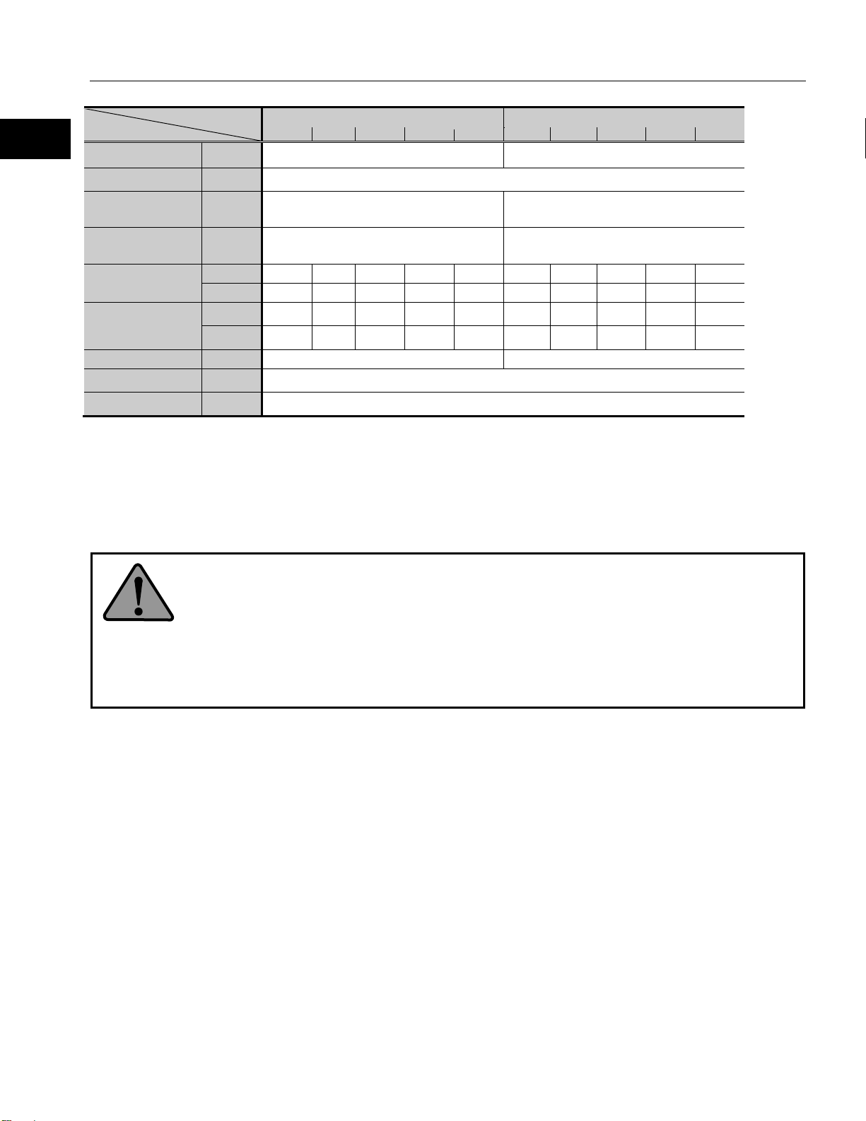
CG type
Model/Ratio
Item
SHA40A
50
80
100
120
160
50
80
100
120
160
REL-230-36, REL-230-40
HA-800□-6D/E-200
REL-230-36, REL-230-40
HA-800□-24D/E-200
Nm
333
548
686
802
841
523
675
738
802
841
kgf・m
34.0
55.9
70.0
81.8
85.8
53.4
68.9
75.3
81.8
85.8
Allowable continuous
torque
Nm
92
156
196
235
315
157
260
327
382
382
kgf・m
9.4
15.9
20.0
24.0
32.1
16.0
26.5
33.3
39
39
Nm/A
rms
25
40
50
60
80
25
40
50
60
80
kgf・
m/A
rms
A
Allowable continuous
current
EMF constant
V/(rpm)
2.8
4.5
5.6
6.7
9.0
2.8
4.5
5.6
6.7
9.0
Phase resistance
(20℃)
Phase inductance
mH
1.2
Inertia
brake)
GD2/4
kg・m2
4.8
12
19
27
49
4.8
12
19
27
49
・
Inertia
(with brake)
GD2/4
kg・m2
5.8
15
23
33
59
5.8
15
23
33
59
kgf・cm・
s2
Permissible moment
load
Nm
849
kgf・m
86.6
Nm/rad
179×104
kgf・
min
One-way positional
accuracy
Repeatability
arc-sec
4
Bi-directional
repeatability
Encoder type
Magnetic absolute encoder
Single motor
Encoder resolution
Motor multi revolution
count
6,553,
600
10,485,
760
13,107,
200
15,728,
640
20,971,
520
6,553,
600
10,485,
760
13,107,
200
15,728,
640
20,971,
520
Mass
(without brake)
Mass (with brake)
kg
13.8
Environmental conditions
Altitude: less than 1,000 m above sea level
Motor insulation
Mounting direction
Can be installed in any direction.
Protection structure
Totally enclosed self-cooled type (IP54)
1-4 Specifications
Combined driver
Max. torque*2
*2*3
Max. rotational speed*2 rpm 80 50 40 33.3 25 80 50 40 33.3 25
Torque constant*2
Max. current*1
*1*2
moment
(without
moment
Moment stiffness
rms
A
rms
Ω 0.19
kgf・cm
J
J
s2
m/arc
2.5 4.1 5.1 6.1 8.2 2.5 4.1 5.1 6.1 8.2
18 18 18 17.6 14.3 27.2 22 19.6 18 14.7
6.0 6.0 6.0 6.0 6.0 9.0 9.0 9.0 8.8 7.2
49 124 194 280 497 49 124 194 280 497
59 150 235 338 601 59 150 235 338 601
*1
53.2
arc-sec
arc-sec
revolution
Output resolution
217(131,072)
216(65,536)
Pulse/rev
kg 13.0
The table shows typical output values of actuators.
*1: If a HA-800□-6D/E driver is combined with a SHA40A actuator, the maximum torque and allowable continuous torque are limited.
*2: Typical characteristics when combined (driven by ideal sine wave) with our drivers.
*3: Value after temperature rise and saturation when the 500 x 500 x 25 [mm] aluminum radiation plate is installed.
*4: Value of phase induced voltage constant multiplied by 3.
*5: For testing conditions, refer to [1-12 Shock resistance] (P51) and [1-13 Vibration resistance ] (P52).
40 30 30 30 30 40 30 30 30 30
±
50 20 20 20 20 50 20 20 20 20
Operating temperature: 0 to 40℃/Storage temperature: -20 to 60℃
Operating humidity/storage humidity: 20 to 80%RH (no condensation)
Resistance to vibration: 25 m/s
No dust, no metal powder, no corrosive gas, no inflammable gas, no oil mist
To be used indoors, no direct sunlight
Insulation resistance: 100MΩ or more (by DC500V insulation tester)
Dielectric strength: AC1,500V/1 min
Insulation class: A
2
(frequency: 10 to 400Hz)/S hock resistance: 300 m/s
2 *4
24
Page 25
1-5 Motor shaft brake
Outline
Model
51
81
101
121
161
Dry non-excitation actuation type (without power-
saving control)
Brake excitation
voltage
Current
(at 20℃)
Current
(at 20℃)
(GD2/4)
kg·m2
(J)
kgf·cm·s2
Allowable number
of normal stops*5
Allowable number
stops*6
11
51
81
101
121
161
11
51
81
101
121
161
Brake excitation
voltage
Current
(at 20℃)
Current
(at 20℃)
(GD2/4)
kg·m2
(J)
kgf·cm·s2
Allowable number
of normal stops*5
Allowable number
stops*6
1-5 Motor shaft brake
The brake is used to hold the motor shaft in place when the power is turned off. With smaller sizes (SHA25A, 32A), the
actuator's built-in circuit controls the voltage supplied to the brake in order to reduce the power consumption while the brake is
actuated.
Be sure to use a DC power supply having proper brake excitation voltage and capable of outputting enough current for the
brake actuation (release).
Specifications
SG/HP type
Item
Type
V DC24V ± 10% (no polarity)*1
SHA20A
consumption
during suction
consumption
during holding
Holding torqu e*3
Inertia moment*3
(Actuator total)
(with brake)
Mass (with brake)*4 kg 2.1
of emergency
A
0.37
rms
A
Sam e as curre nt consumption during suctio n
rms
Nm 31 49 61 73 97
kgf·m 3.1 5.0 6.2 7.4 9.9
0.26 0.65 1.0 1.4 2.6
2.7 6.6 10 15 26
100,000 times
200 times
Item
Type Dry non-excitation actuation type (with power-saving control)
consumption
during suction
consumption
during holding
Model
V DC24V ± 10% (no polarity)*1
A
0.8*2 0.8*2
rms
A
0.3 0.3
rms
SHA25A SHA32A
Holding torqu e*3
Inertia moment*3
(Actuator total)
(with brake)
Mass (with brake)*4 kg 5.1 3.1 9.7 6.2
of emergency
25
Nm 11 51 81 101 121 161 22 102 162 202 242 322
kgf·m 1.1 5.2 8.3 10 12 16 2.2 10 17 21 25 33
0.034 0.66 1.7 2.6 3.7 6.6 1.7 2.3 5.9 9.2 13 23
0.35 6.7 17 26 38 67 17 24 60 94 135 238
100,000 times
200 times
Page 26
1
2
3
4
5
6
7
8
9
10
11
付
Outline
SG
Model
Item
SHA40A
SHA58A
51
81
101
121
161
81
101
121
161
Type Dry non-excitation actuation type (without power-saving control)
Brake excitation voltage
V
DC24V ± 10% (no polarity)*1
Current consumption
during suction (at 20℃)
Current consumption
during holding (at 20℃)
Nm
204
324
404
484
644
1220
1520
1820
2420
kgf·m
21
33
41
49
66
124
155
185
246
(GD2/4)
kg·m2
(J)
kgf·cm·s2
Mass (with brake)*4
kg
10.7
32
Allowable number of
normal stops*5
Allowable number of
emergency stops*6
Model
Item
SHA65A
81
101
121
161
Dry non-excitation actuation type (wi tho ut
power-saving control)
Brake excitation voltage
V
DC24V±10% (no polarity)*1
Current consumption
during suction (at 20℃)
Current consumption
during holding (at 20℃)
Same as current consumption during
suction
Nm
1220
1520
1820
2420
kgf·m
124
155
185
246
(GD2/4)
kg·m2
(J)
kgf·cm·s2
Mass (with brake)*4
kg
40
Allowable number of
normal stops*5
Allowable number of
emergency stops*6
Model
50
80
100
120
160
50
80
100
120
160
Dry non-excitation actuation type (without power-
saving control)
Dry non-excitat ion actuation type (with power-
saving control)
Brake excitation
voltage
Current consumption
20℃)
Current consumption
20℃)
(GD2/4)
kg·m2
(J)
kgf·cm·s2
Allowable number of
normal stops*5
Allowable number of
emergency stops*6
Holding torqu e*3
Inertia moment*3
(Actuator total)
(With brake)
Type
A
0.7 0.9
rms
A
Same as current consumption during suct io n
rms
6.1 15 24 34 61 106 165 237 420
62 157 244 350 619 1090 1690 2420 4290
100,000 times
200 times
A
0.9
rms
1-5 Motor shaft brake
A
rms
Holding torqu e*3
Inertia moment*3
(Actuator total)
(With brake)
100,000 times
200 times
120 187 268 475
1230 1910 2740 4850
CG
type
Item
Type
V
during suction (at
during holding (at
Holding torqu e*3
Inertia moment*3
(Actuator total)
(With brake)
Mass (with brake)*4 kg 2.7 4.1
A
0.37 0.8 *2
rms
A
Same as current consum pt io n during suction 0.3
rms
Nm
kgf·m
30 48 60
3.1 4.9 6.1
0.23 0.6 0.94
2.4 6.1 9.6
100,000 times
200 times
SHA20A SHA25A
DC24V±10%(no polarity)*1
72 96 50 80 100 120 160
7.3 9.8 5.1 8.2 10 12 16
1.3 2.4 0.60 1.5 2.4 3.4 6.1
14 24 6.1 16 24 35 62
26
Page 27
1-5 Motor shaft brake
Outline
Model
50
80
100
120
160
50
80
100
120
160
Dry non-excitation actuation type (with power-
saving control)
Dry non-excitat ion actuation type (without
power-saving control)
Brake excitation
voltage
Current consumption
20℃)
Current consumption
20℃)
(GD2/4)
kg·m2
(J)
kgf·cm·s2
Allowable number of
normal stops*5
Allowable number of
emergency stops*6
WARNING
Item
SHA32A SHA40A
Type
during suction (at
during holding (at
Holding torqu e*3
Inertia moment*3
(Actuator total)
(With brake)
Mass (with brake)*4 kg 8.0 13.8
V DC24V±10%(no polari t y)*1
A
0.8 *2 0.7
rms
A
0.3 Sam e as cur re nt cons um pt io n during suction
rms
Nm 100 160 200 240 320 200 320 400 480 640
kgf·m 10 16 20 24 33 20 33 41 49 65
2.0 5.1 7.9 11 20 5.8 15 23 33 59
20 52 81 116 207 59 150 235 338 601
100,000 times
200 times
*1: Power supply is user’s responsibility. Use a power supply capable of outputting enough current consumption during suction for the brake.
*2: The durat i on for current c onsum ption during suction is 0.5 second or less for the power supply of DC24V ± 10%.
*3: The values are converted for the output shaft of the actuator.
*4: The values present total mass of the actuator.
*5: The s ervice tim e for normal holdi ng is assured when the brake activates at motor shaft rotation speed of 150 rpm or less.
*6: The s ervice time for emergency stop is assured when the brake activates at motor speed of 3,000 rpm or less provided the load inertia
moment is 3 times of less than that of the actuator.
The motor shaft holding brake cannot be used for deceleration.
Do not use the holding brake more than the allowable number of normal brakings (100,000
times at the motor shaft rotation speed of 150 rpm or less) or allowable number of
emergency stops (200 times with the motor shaft rotation speed of 3,000 rpm, provided
the load inertia moment is 3 times or less than that of the actuator).
Exceeding the allowable number of normal stops or allowable number of emergency stops
may deteriorate holding torque, and may co nsequently fail to properly serve as a brake.
27
Page 28
1
2
3
4
5
6
7
8
9
10
11
付
Outline
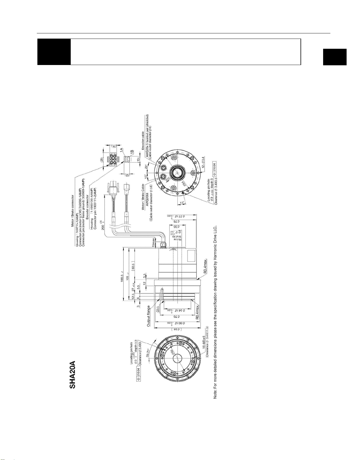
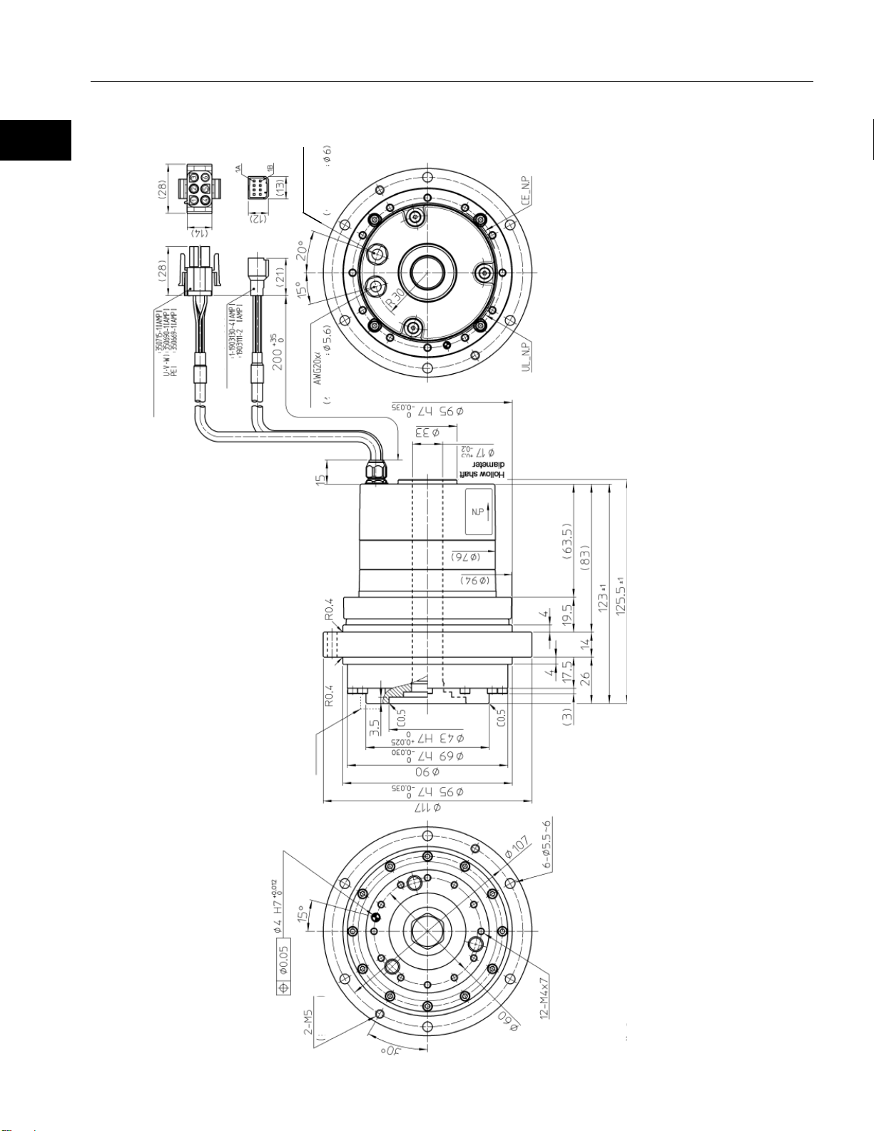
Note: The dimension toleranc es that are not specified vary depending on the manufacturing method. Pleas e ch eck t he
confirmation drawing or contact us
1-6 External dimensions
SHA20A-SG
Unit: mm
1-6 External dimensions
for dimension tolerances not shown
28
Page 29
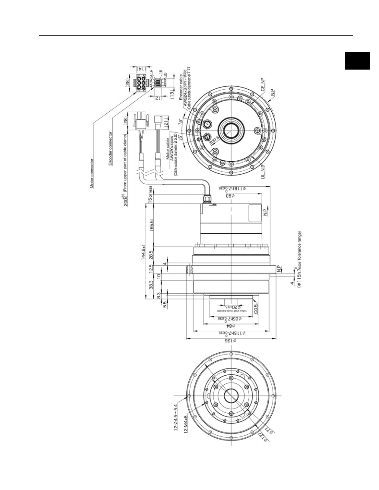
1-6 External dimensions
Outline
Encoder cable
AWG28 x 3 sets
with shield
Cable outer
diameter
Motor connector
Housing
Pin contact (Motor
Pin contact (Motor
Encoder connector
Housing
Tab contact
Motor cable
Cable outer
diameter
4-core
Output rotary unit
Jacking
holes
Note: The dimension toleranc es that are not specified vary depending on the manufacturing method. P leas e chec k t he
confirmation drawing or contact us for dimension tolerances not shown
LipC0.5 chamfering
Depth 7
or less
or less
or less
SHA20A-CG
Unit: mm
29
Page 30
1
2
3
4
5
6
7
8
9
10
11
付
Outline
Note: The dimension tolerances that are not specified vary depending on the manufacturing method. Please check the
confirmation drawing or contact us for dimension toleranc
SHA25A-HP Unit: mm
1-6 External dimensions
es not shown
30
Page 31

1-6 External dimensions
Outline
Note: The dimension tolerances that are not specifi ed vary depending on the manufacturing method. Please check the
confirmation drawing or contact us for dimension tolerances not shown
SHA25A-SG
Unit: mm
31
Page 32

1
2
3
4
5
6
7
8
9
10
11
付
Outline
Encoder cable
Motor cable
AWG24 x 3 sets + shield
(Cable Outer diameter:φ7.7)
AWG20x4 core
(Cable outer dia
AWG24 x 3 sets + shield
(Cable Outer diameter:φ7.7)
or less
or less
R0.4 or less
Output rotary unit
Encoder connector Motor connector
Housing
Tab contact
Housing
Pin
contact
Pin contact Motor
Depth 8
Lip C1 chamfering
(Jacking holes)
R0.4 or less
Note: The dimension tolerances that are not specified vary depending on the manufacturing method. Please check the
confirmation drawing or contact us f
SHA25A-CG
Unit: mm
1-6 External dimensions
.:φ5.6)
or dimension tolerances not shown
Motor
32
Page 33

1-6 External dimensions
Outline
Note: The dimension tolerances that are not specified vary depending on the manufacturing method. Please check the
confirmation drawing or contact us for dimension tolerances not shown
SHA32A-HP
Unit: mm
33
Page 34

1
2
3
4
5
6
7
8
9
10
11
付
Outline
SHA32A-SG
Note: The dimension tolerances that are not specified vary depending on t he manufacturing m ethod. Please check t he
confirmation drawing or contact us for dimension tolerances not shown
Unit: mm
1-6 External dimensions
34
Page 35

1-6 External dimensions
Outline
Note: The dimension tolerances that are not specified vary depending on the manufacturing method. Please check the
nfirmation drawing or contact us for dimension tolerances not shown
SHA32A-CG
Unit: mm
co
35
Page 36

1
2
3
4
5
6
7
8
9
10
11
付
Outline
Note: The dimension tolerances that are not specified vary depending on the manufacturing method. Please check the
confirmation drawing or contact us for dimension tolerances not shown
SHA40A-SG
Unit: mm
1-6 External dimensions
36
Page 37

1-6 External dimensions
Outline
Note: The dimension tolerances that are not specified vary depending on the manufacturing method. Please check the
confirmation drawing or contact us for dimension tolerances not shown
Encoder cable
Motor cable
or less
or less
Or
Encoder connector
Housing
Housing
Tab contact
Motor connector
Pin contact (Motor
Pin contact (Motor
Lip C1 chamfering
Jacking holes
AWG24 x 3 sets + shield
(Cable Outer diameter:φ7.7)
AWG16 x 4 core
(Cable outer dia.:φ
Output rotary unit
Deapth 10
SHA40A-CG
Unit: mm
7.8)
less
37
Page 38

1
2
3
4
5
6
7
8
9
10
11
付
Outline
Note: The dimension toleranc es that are not specified vary depending on the manufacturing method. Please check the
confirmation drawing or contact us for dimension tolerances not shown
SHA58A-SG
1-6 External dimensions
Unit: mm
38
Page 39

1-6 External dimensions
Outline
Note: The dimension tolerances that are not specified vary depending on the manufacturing method. Please check the
confirmation drawing or contact us for dimension tolerances not shown
SHA65A-SG
Unit: mm
39
Page 40

1-7 Mechanical accurac y
1
2
3
4
5
6
7
8
9
10
11
付
Outline
Accuracy items
SHA20A
SHA25A
SHA32A
SHA40A
SHA58A
SHA65A
0.035
0.020)
0.040
0.020)
2. Output shaft radial run-out
0.030
0.035
0.040
0.045
0.050
0.050
3. Parallelism between the output shaft
and actuator mounting surface
4. Parallelism between the output shaft
and actuator mounting surface
5. Concentricity between the output
shaft and actuator mounting diameter
6. Concentricity between the output
shaft and actuator mounting diameter
Accuracy items
SHA20A
SHA25A
SHA32A
SHA40A
1. Output shaft surface runout
0.010
0.010
0.010
0.010
2-1. Output sh a ft r a dial run-out (Outside
inlay)
2-2. Output shaft radial run-out (Inside
inlay)
3. Parallelism between the output shaft
and actuator mounting surface
4. Parallelism between the output shaft
and actuator mounting surface
5. Concentricity between the output
shaft and actuator mounting diameter
6. Concentricity between the output
shaft and actuator mounting diameter
A 5 ◎ 2 A B 1
A 6 ◎
3
B
4
B
2-1 A B 1 A 6 ◎
4
B
2-2 A 5
◎
CG type
SG/HP type
1-7 Mechanica l accuracy
SHA series mechanical accuracy of the output shaft and mounting flange:
SG/HP type unit: mm
1. Output shaft surface runout 0.030
0.030 0.035 0.040 0.045 0.050 0.050
0.055 0.050 0.055 0.060 0.070 0.070
0.030 0.035 0.040 0.045 0.050 0.050
0.045 0.060 0.065 0.070 0.080 0.080
Note: All values are T.I.R. (Total Indicator Reading).
The values in parenthesis are those combined with the HPF hollow shaft planetary speed reducer
CG type
Note: All values are T.I.R. (Total Indicator Reading).
unit: mm
0.010 0.010 0.010 0.010
0.015 0.015 0.015 0.015
0.030 0.030 0.035 0.035
0.040 0.040 0.045 0.045
0.050 0.050 0.055 0.060
0.060 0.060 0.065 0.070
(
(
0.045 0.050 0.050
40
Page 41

1-7 Mechanical accurac y
Outline
(1)
(2)
(3)
(5)
(6)
(4)
The reported values are measured as follows:
1 Output shaft surface runout
The indicator is fixed and measures the axial run-out
(T.I.R.) of the outermost circumference of the output
shaft for one revolution.
2 Output shaft radial run-out
The indicator is fixed and measures the radial run-out
(T.I.R.) of the output shaft for one revolution.
3,4 Concentricity between the output shaft and actuator
mounting diameter
The indicator is mounted on the output shaft
and measures the axial run-out (T.I.R.)
of the outermost circumference of the
mounting surface (on both the output shaft
side and opposite side) for one revolution.
5,6 Concentricity between the output shaft and actuator
mounting diameter
The indicator on the output rotary unit measures the
radial runout ( maximum runout width) of the fitting par t
(both on the outp ut shaft side and op posite side) of th e
output rotary unit per revolution.
41
Page 42

1-8 One-Way Positional accuracy
1
2
3
4
5
6
7
8
9
10
11
付
Outline
Size
Reduction ratio
11:1
120
120
- -
51:1
60
50
50
50
-
81:1 or more
50
40
40
40
40
40
Size
Reduction ratio
50:1
60
50
40
40
80:1 or more
50
40
30
30
1-8 One-Way Positional accuracy
The one-way positioning accuracy is defined as the maximum positional difference between the
commanded position and the actual stop position when a series of positioning moves are performed
in the same rotation direction. (Refer to JIS B-6201-1987).
The SHA actuator incorporates a Harmonic Drive gear which inherently has high rotational position accuracy.
Because of the gearing’s high ratio, any rotational error at the input (i.e. motor shaft position error or motor
feedback error) is reduced by a factor of the ratio (1/ratio) and typically becomes negligible at the output.
Therefore most of the error is represented by the transmission error of the Harmonic Drive gear itself.
The one-way positional accuracy is shown in the table below:
SG/HP (Unit: arc-sec)
CG (Unit: arc-sec)
SHA20A SHA 25A SHA32A SHA40A SHA58A SHA65A
-
SHA20A SHA25A SHA32A SHA40A
-
-
42
Page 43

1-8 One-Way Positional accuracy
Outline
Model
Reduction ratio
Ratio to full speed
5 ±5 ±4 ±4
Model
Reduction ratio
50:1
75
60
60
50
80:1 of more
30
25
25
20
P1
P2
Stop position
X
Repeatability
X/2
P1
P1’
Stop position after forward rotation
X1
X2
P2
P2’
P7’
P7
X7
Repeatability (CG type)
The repeatability is measured by moving to a given theoretical position seven times, each time approaching from the same
direction. The actual po sit ion o f the output shaft is mea sur ed each time and repeatability is calculated as the 1/2 of the
maximum difference of the seven data points. Measured values are indicated in angles (arc-sec) prefixed with "±"..
CG type (Unit: arc-sec)
SHA20A SHA25A SHA32A SHA40A
±
*P1~P7:
X:Maximum error
:±
Bi-directional repeatability (CG type)
For the "bi-directional repeatability", the shaft is rotated beforehand in the forward (or reverse) direction and the stop position
for that rotation is set as the reference position. An instruction is given to rotate the shaft in the same direction and from the
stopped position, the same instruction is given in the reverse (or forward) direction and the difference between the stop
position after this rotation and the reference position is measured. The average value from repeating this 7 times in each
direction is shown and the maximum value measured at the 4 locations on the output shaft is shown.
CG type (Unit: arc-sec)
SHA20A SHA25A SHA32A SHA40A
*P1~P7:
P1’~P7’:Stop position after reverse rotation
X1~X7:Difference between the stop positions
after forward and reverse rotations
Reverse positional accuracy:|X1+X2+・・・+X7|/7
43
Page 44
1-9 Encoder specifications (Absolute encoder)
1
2
3
4
5
6
7
8
9
10
11
付
Outline
Magnetic sensor/electronic battery backup type
type)
Resolution per motor revolution
17 bits (217: 131,072 pulses)
Maximum cumulative motor shaft
revolutions
Maximum permissible motor shaft
rotational speed
Check method in which two identical single revolution detectors are compared
Check method in which two identical cumulative revolution counters are compared
Backup time by external battery*2
1 year (when power is not supplied)
30 minutes (after 3 hours of charge, ambient temperature of 25℃, axis stopped)
(For backup while the driver and encoder are disconnected briefly)
Encoder resolution
2
131,072)
Reduction ratio
11:1
51:1
81:1
101:1
121:1
161:1
Resolvable angle per
pulse (approximate)
Approx.
0.9
Approx.
0.2
Approx.
0.082
Approx.
0.061
Resolution at the
output shaft
Resolvable angle per
pulse (approximate)
Approx.
0.2
Approx.
0.12
Approx.
0.082
Approx.
0.062
1-9
The absolute encoder used in the SHA series is a multi-turn magnetic absolute en code r. This encoder consists of
17 bit single turn absolute encoder and a 16 bit cumulative counter for detecting the number of total revolutions.
This encoder constantly monitors the absolute machine position and, by means of an external backup battery*2, stores the
position regardless of whether the driver or external controller power is turned ON or OFF. Accordingly, once the origin is
detected when the machine is first installed, homing is not required for subsequent power ON operation. This facilitates an
easy recovery after a power failure or machine breakdown.
Additionally, when the power is ON, the single revolution absolute position and the number of revolutions is calculated with
dual-redundant systems and comparison checks are continually performed on the data. This highly reliable design allows for
encoder errors to be self-detected should they ever occur.
In addition, a backup capacitor is installed in the encoder to retain the absolute position data even when the actuator is
disconnected from the driver for the purpose of maintenance, etc. (Internal backup). It is recommended that you replace the
backup battery in the HA-800 driver while the driver is receiving power.
Encoder specifications (Absolute encoder)
Specifications
Type*1
Safety/redundancy
(Single rotation optic, multiple revolution magnetic sens or/electronic battery backup
16 bits (216: 65,536 revolutions cumulatively)
7000rpm
・
・
Internal backup time
*1: Size 20 is equipped with an optical encoder; other models are equipped with a magnetic encoder.
*2 : Battery box is sold separately (Recommended battery is Maxell ER 17/33 battery)
Resolution at the output shaft
17
(
Resolution at the
output shaft
Reduction ratio
Pulse/rev 1,441,792 6,684,672 10,616,832 13,238,272 15,859,712 21,102,592
Sec.
Pulse/rev
Sec
50:1 80:1 100:1 120:1 160:1
6,553,600 10,485,760 13,107,200 15,728,640 20,971,520
Approx. 0.12 Approx. 0.1
Approx. 0.1
Absolute position data
[Absolute position] indicates the absolute position within one motor shaft revolution, while [multi revolution]
indicates the num ber of motor revolutions. The pos ition of the actuator output s haft is obtained by the following
formula:
Position of actuator ou tput shaft = (Absolute position + Multi re volution data x Encoder resolution) / Reduction
ratio
44
Page 45

1-9 Encoder specifications (Absolute encoder)
Outline
Transfer of encoder data
Data is transferred via bi-directional communication in a normal condition while power is supplied. When the driver
control power supply is turned OFF and the driver enters the battery backup mode, communication stops.
Output shaft single revolution absolute model (Option)
With the standard actuator, when it continues to rotate in just one direction, the absolute encoder eventually
exceeds the number of revolutions that can be detected with multi-revolution detection and it becomes impossible
to manage position information accurately.
With the output s haft singl e revol ution abs olute m odel, each time th e outp ut shaf t turns thr ough sing le re volution,
the cumulative multi rev olution counter is cleared to 0. This is how position inform ation is accurately managed
when the shaft continuously turns in just one direction.
45
Page 46

1-10 Output Stiffness
1
2
3
4
5
6
7
8
9
10
11
付
Outline
Model
Item
Reduction ratio
50:1 or more
11:1
50: 1 or more
11:1
50:1 or more
Nm/rad
25.2×10⁴
37.9×10⁴
39.2×10⁴
86.1×10⁴
100×104
38.7×10³
kgf・m/arc-min
7.5
11.3
11.6
25.7
29.6
Model
Item
Reduction ratio
50:1 or more
80:1 or more
80:1 or more
Nm/rad
179×104
531×104
741×104
kgf・m/rad
183×103
542×103
756×103
kgf・m/arc-min
53.2
158
220
Gradient
CAUTION
Sleeve
(hollow shaft)
Output shaft
1-10 Output Stiffness
Moment stiffness
The moment stiffness refers to the torsional stiffness when a moment load is applied to the output
shaft of the actuator (shown in the figure).
For example, whe n a load is app lied to th e end of a n arm attached o n the ou tput shaft of the ac tuator, the face of
the output shaft of the actuator tilts in proportio n to the moment loa d. The moment stiff ness is expressed as the
load/gradient angle.
SHA20A SHA25A SHA32A
Load
Moment
stiffness
Moment
stiffness
kgf・m/rad 25.7×10³
SHA40A SHA58A SHA65A
40×103 87.9×10³ 102×103
Do not apply torque, load or thrust to the sleeve (hollow shaft) directly.
The sleeve (hollow shaft) is adhered to the output rotary shaft. Accordingly, the adhered
sleeve may be detached from the output rotary shaft if a torque or load is applied to the
sleeve (hollow shaft).
Do not apply any torque, moment load or thr ust load directly to the sleeve (hollow shaft).
46
Page 47

1-10 Output Stiffness
Outline
Model
SHA20A
SHA25A
SHA32A
SHA40A
50:1
51:1
80:1 or
more
50:1
51:1
80:1 or
more
50:1
51:1
80:1 or more
50:1
51:1
80:1 or
more
Nm
7.0
14
29
54
kgf・m
0.7
1.4
3.0
5.5
x104 Nm/rad
1.3
1.6
2.5
3.1
5.4
6.7
10
13
kgf・m/arc min
0.38
0.47
0.74
0.92
1.6
2.0
3.0
3.8
θ
x10-4 rad
5.2
4.4
5.5
4.4
5.5
4.4
5.2
4.1
arc min
1.8
1.5
1.9
1.5
1.9
1.5
1.8
1.4
Nm
25
48
108
196
kgf・m
2.5
4.9
11
20
X104 Nm/rad
1.8
2.5
3.4
5.0
7.8
11
14
20
kgf・m/arc min
0.52
0.75
1.0
1.5
2.3
3.2
4.2
6.0
θ
x10-4 rad
15.4
11.3
15.7
11.1
15.7
11.6
15.4
11.1
arc min
5.3
3.9
5.4
3.8
5.4
4.0
5.3
3.8
x104 Nm/rad
2.3
2.9
4.4
5.7
9.8
12
18
23
kgf・m/arc min
0.67
0.85
1.3
1.7
2.9
3.7
5.3
6.8
3
2
2
K
TT −
+θ=ϕ
2
1
1
K
TT −
+θ
=ϕ
1K
T
=ϕ
angle
Torsional
* :ϕ
Torsional Stiffness
The speed reducer uses (1) s peed ratio 50 or more for the HarmonicDrive® gear and (2) speed
ratio 11 for the HPF hollow shaft planetary series. The structures of the speed reducers are
different, so their rotation direction torsional stiffness are different. Refer to individual
If a torque is applied t o the outp ut shaft of the actuato r with the input lock ed, the output shaft will torsio nal def lect
roughly in proportion to the torque.
The upper right figure shows the torsional angle of the
output shaft when a torque, starting from zero and
increased to positi ve side [+T
applied to the out put shaft. This [tor que vs. tor sional angle]
diagram, typically follows a loop of 0-A-B-A’-B’-A. The
torsional stiffness of the SHA series actuator is expres sed
by the slope of this [torque vs. torsional angle diagram]
representing a spring constant (unit: Nm/rad).
As shown by lower right figure, this [torque vs. torsional
angle] diagram is divid ed into three regions a nd the spring
constants in these regions are expressed by K
respectively.
1:Spring constant for torque region 0 to T1
K
K
2:Spring constant for torque region T1 to T2
K
3:Spring constant for torque region over T2
The torsional angle for each region is expressed as follows:
Range where torque T is T1 or below:
Range where torque T is T
Range where torque T is T
The table below shows the averages of T
characteristics shown on the graphs and tables.
0] and negative side [ –T0], is
1, K2, and K3,
1 to T2:
2 to T3:
1 to T3, K1 to K3, and θ1 to θ2 for each actuator.
Reduction ratio
T1
K1
1
T2
K2
2
K3
47
Page 48

1-10 Output Stiffness
1
2
3
4
5
6
7
8
9
10
11
付
Outline
Model
SHA58A
SHA65A
Reduction ratio
81:1 or more
81:1 or more
Nm
168
235
kgf・m
17
24
x104 Nm/rad
40
54
kgf・m/arc min
12
16
θ
x10-4 rad
4.1
4.4
arc min
1.4
1.5
Nm
598
843
kgf・m
61
86
X104 Nm/rad
61
88
kgf・m/arc min
18
26
θ
x10-4 rad
11.1
11.3
arc min
3.8
3.9
x104 Nm/rad
71
98
kgf・m/arc min
21
29
Model
SHA20A
SHA25A
SHA32A
SHA40A
Reduction
ratio
50:1
51:1
80:1
or more
50:1
51:1
80:1
or more
50:1
51:1
80:1
or more
50:1
51:1
80:1
or more
2 arc min
8
11
15
21
31
45
63
88
4 arc min
19
25
35
51
77
108
144
208
6 arc min
30
43
56
84
125
178
233
342 Model
SHA58A
SHA65A
Reduction
ratio
81:1
or more
81:1
or more
2 arc min
273
360
4 arc min
636
876
6 arc min
1050
1450
T1
K1
1
T2
K2
2
K3
The table below shows reference torque values calculated for different torsional angle. (Unit: N・m)
48
Page 49

1-10 Output Stiffness
Outline
Size • ratio
Item
SHA25A
SHA32A
11
11
arc-min
3 3 10-4rad
8.7
8.7
Rated torque (TR)
Nm
21
44
Torsional quantity
by TR x 0.15 (D)
arc-min
2.0
1.7
Torsional stiffness
(A/B)
kgf・m/arc-min
1.7
3.5
x10-4Nm/rad
5.70
11.7
T-TL
: total torsional quantity
A/B: torsional stiffness
Fig. 1 Torque vs. torsional angle diagram
Torsional angle
Torque
Hysteresis loss
= backlash
TR: rated output torque
A/B
D: torsional quantity o
side given by T
(1) (5)
(2)
(4)
(3)
Torsional Stiffness
(Ratio 11: HPF)
If a torque is applied t o the outp ut shaft of the ac tuator with the inp ut lock ed, the outp ut shaft will tor sional def lect
roughly in proportion to the torque. When the values for torque are gradually changed in sequence from (1)
Rated output torqu e in the positive r otation direction→(2) zero→(3) Rated output torque in the negative rotation
direction→(4) zero→( 5) Rated output torqu e in the positive rotati on direction, the values follow a l oop (1)→(2)→
(3)→(4)→(5) (returns to (1)) shown in Fig.1 [torque vs. torsional angle diagram].
The gradient of the region [Rated output torque] from [0.15 x rated output torque] is small, and the torsional
stiffness of the HPF series is the average of this gradient. T he gradient of the region [ 0.15 x rated output torque]
from [zero torque] is l arge. This gradient is cause d b y sem i-partial contact in the m eshing region an d un even lo ad
distribution from light loads and so forth on the planet gears.
An explanation is pro vided below on ho w to calcul ate the total tor sional qua ntity o n one side f rom a no-load state
after a load has been applied by the speed reducer.
θ=D+
A
B
θ
D: torsional quantity on one side given by rated output torque x
0.15 torque
T: load torque
TL: rated output torque x 0.15 torque (= T
R x 0.15)
The zero torque part widths of (2) and (4) in the
figure on the right [torque vs. torsional angle diagram]
is called the hysteresis loss. For the HPF series,
backlash is defined as hysteresis loss [rated output
torque in the negative rotation direction] from
[rated output torque in the positive rotation direction].
The HPF series has a backlash of less than
3 minutes (less than 1 minute with special
products) with factory settings.
Backlash
on one side given
: torsional stiffness
10-4rad 5.8 4.9
x 0.15
R
n one
49
Page 50

1-11 Direction of rotation
1
2
3
4
5
6
7
8
9
10
11
付
Outline
Set
value
FWD command
pulse
REV command
pulse
CCW
direction
CCW
direction
Set
value
FWD command
pulse
REV command
pulse
CCW
direction
CCW
direction
Counterclockwise rotat ion direction
1-11 Direction of rotation
SG/HP
As a default, Forward rotation direction of the actuator is defined as counterclockwise (CCW)
rotation as viewed from the load shaft when a Forward command (FWD command pulse) is given
to a SHA series actuator from a HA-800 driver
This rotation direction can be changed on the HA-800 driver by selecting [SP50: Command polarity setting]
under [System parameter mode 3].
Setting of [SP50: Command polarity setting]
Setting
0
1
(counterclockwise)
CW (clockwise)
direction
CW (clockwise)
direction
(counterclockwise)
Default
CG
As a default, the r otation direction is defined as cloc kwise (CW ) rotation as viewed from the output shaft when a
FWD command pulse is given from a HA-800 driver.
This rotation direction c an be cha nge d on the HA-800 driver by selecting [SP 50: Com m and polarit y setti ng] unde r
[System parameter mode 3].
Setting of [SP50: Command polarity setting]
Setting
0
1
(clockwise) direction
CW
(counterclockwise)
(counterclockwise)
CW
(clockwise) dire ct i on
Default
50
Page 51

1-12 Shock resistance
Outline
Shock
resistance test
Right
Left
Up
Do
wn
Rear
Front
1-12 Shock resistance
The actuator can withstand a 300 m/s2 shock in all directions (up/down, left/right, and
front/rear):
Impact acceleration: 300 m/s2
In our shock resistance tes t, the actuat or is tested 3 times in e ach direct ion. Actu ator operati on is not g uarantee d
in applications where impact exceeding the above value is constantly applied.
51
Page 52

1
2
3
4
5
6
7
8
9
10
11
付
Outline
Vibration
Right
Left
Up
Do
wn
Rear
Front
1-13 Vibration resistance
1-13 Vibration resistance
The actuator can withstand a 25 m/s
(up/down, left/right, and front/rear):
Vibration acceleration: 25 m/s
In our test, the actuator is tested for 2 hours in each direction at a vibration frequency sweep period
of 10 minutes.
resistance
test
2
vibration acceleration (frequency 10 to 400 Hz) in all directions
2
(frequency: 10 to 400Hz)
52
Page 53

1-14 Operable range
Outline
1-14 Operable range
The graph on the next page indicates the torque/s peed operating ra nge for the SHA actuators (combined wi th a
HA-800 driver) is selected. For details, refer to [Chapter 2 SHA series selection].
1. Continuous motion range
The range allows continuous operation of the actuator.
2. 50% duty range
range indicates the torque/s peed where 50% dut y cycl e operation is permitted (the ratio of oper ati ng t ime and idle
time is 50:50).
Limit the operation c ycle to a period of several minutes , and keep it within a range where the o verload alarm of
the driver does not sound.
3. Acceleration and deceleration range
This range indicates the torque/speed which the actuator can be operated momentarily. The range allows
instantaneous operation like acceleration and deceleration.
The continuous and 50% duty motion ranges in each graph are m easured when the actuator is mounted to an
aluminum heatsink as specified in the graph.
When the SHA SG is operated at a constant speed (motor shaft speed of 1,000 rpm or less) in the
same direction under a constant load torque in a condition where the output shaft is facing up
(output shaft is facing down with CG type), improper lubrication of the bu ilt-in speed reduc er may
cause abnormal soun d or wear, leading to a sh or ter lif e. Improper lubrication can be prevented by
changing the speed in the operation pattern, such as by periodically stopping the actuator.
However, the planetary speed reducer (11:1) is not included.
53
Page 54

1
2
3
4
5
6
7
8
9
10
11
付
Outline
SHA20A51SG
SHA20A81SG
SHA20A101SG
SHA20A121SG
SHA20A161SG
SHA20A SG
■
■
1-14 Operable range
■
■
■
54
Page 55

1-14 Operable range
Outline
SHA25A51SG
SHA25A81SG
SHA25A101SG
SHA25A121SG
SHA25A161SG
放熱板:350*350*18
0
25
50
75
100
125
150
0 20 40 60 80 100
回転速度 [r/min]
トルク [Nm]
加減速運転領域
連続使用領域
50%デューティ領域
mm
放熱板:350*350*18
0
25
50
75
100
125
150
175
200
0 20 40 60 80
回転速度 [r/min]
トルク [Nm]
加減速運転領域
連続使用領域
50%デューティ領域
mm
放熱板:350*350*18
0
50
100
150
200
250
0 10 20 30 40 50
回転速度 [r/min]
トルク [Nm]
加減速運転領域
連続使用領域
50%デューティ領域
mm
放熱板:350*350*18
0
50
100
150
200
250
0 10 20 30 40 50
回転速度 [r/min]
トルク [Nm]
加減速運転領域
連続使用領域
50%デューティ領域
mm
放熱板:350*350*18
0
50
100
150
200
250
0 10 20 30 40
回転速度 [r/min]
トルク [Nm]
加減速運転領域
連続使用領域
50%デューティ領域
mm
Radiation plate: 350*350*18 mm
Motion range during
deceleration
50% duty motion range
Continuous
motion range
Rotation speed [r/min]
Torque [Nm]
Radiation plate: 350*350*18 mm
Motion range during
50% duty motion range
Continuous
Rotation speed [r/min]
Torque [Nm]
Radiation plate: 350*350*18 mm
Motion range during
50% duty motion range
Continuous
motion range
Rotation speed [r/min]
Torque [Nm]
Radiation plate: 350*350*18 mm
Motion range during
50% duty motion range
Continuous
Rotation speed [r/min]
Torque [Nm]
Radiation plate: 350*350*18 mm
Motion range during
50% duty motion range
Continuous
motion range
Rotation speed [r/min]
Torque [Nm]
SHA25A SG (Specifications for motor input voltage of 100V)
■
■
■
acceleration and
acceleration and
deceleration
■
acceleration and
deceleration
motion range
acceleration and
deceleration
55
■
acceleration and
deceleration
motion range
Page 56

1
2
3
4
5
6
7
8
9
10
11
付
Outline
SG/HP
SHA25A11HP
SHA25A51SG
放熱板:350 *350* 18
0
25
50
75
100
125
150
0
20 40 60 80 100 120
回転速度 [r/min]
トルク [Nm]
加減速運転領域
連続使用領域
50%デューティ領域
mm
SHA25A101SG
放熱板: 350*3 50*18
0
50
100
150
200
250
0 10 20 30 40 50 60
回転速度 [r/min]
トルク [Nm]
加減速運転領域
連続使用領域
50%デューティ領域
mm
SHA25A81SG
放熱板:350 *350* 18
0
25
50
75
100
125
150
175
200
0 20 40 60 80
回転速度 [r/min]
トルク [Nm]
加減速運転領域
連続使用領域
50%デューティ領域
mm
SHA25A121SG
放熱板:350*350*18
0
50
100
150
200
250
0 10 20 30 40 50
回転速度 [r/min]
トルク [Nm]
加減速運転領域
連続使用領域
50%デューティ領域
mm
SHA25A161SG
放熱板:350*350*18
0
50
100
150
200
250
0 10 20 30 40
回転速度 [r/min]
トルク [Nm]
加減速運転領域
連続使用領域
50%デューティ領域
mm
放熱板:350*350*18 mm
トルク [Nm]
Radiation plate: 350*350*18 mm
Motion range during
50% duty motion range
Continuous
motion range
Rotation speed [rpm]
Torque [Nm]
Radiation plate: 350*350*18 mm
Motion range during
deceleration
50% duty motion range
Continuous
motion range
Rotation speed [rpm]
Torque [Nm]
Radiation plate: 350*350*18 mm
Motion range during
50% duty motion range
Continuous
motion range
Rotation speed [rpm]
Torque [Nm]
Radiation plate: 350*350*18 mm
Motion range during
deceleration
50% duty motion
range
Continuous
motion range
Rotation speed [rpm]
Torque [Nm]
Radiation plate: 350*350*18 mm
Motion range during
50% duty motion range
Continuous
motion range
Rotation speed [rpm]
Torque [Nm]
Radiation plate: 350*350*18 mm
Motion range during
50% duty motion range
Continuous
motion range
Rotation speed [rpm]
Torque [Nm]
SHA25A (Specifications for motor input voltage of 200V)
■
■
■
acceleration and
deceleration
acceleration and
deceleration
acceleration and
deceleration
1-14 Operable range
■
acceleration and
■
acceleration and
■
acceleration and
deceleration
56
Page 57

1-14 Operable range
Outline
SHA32A11HP
SHA32A51SG
放熱板:400*400*20
0
50
100
150
200
250
300
0
20 40 60 80 100
回転速度 [r/min]
トルク [Nm]
加減速運転領域
連続使用領域
50%デューティ領域
mm
SHA32A81SG
放熱板:400 *400* 20
0
50
100
150
200
250
300
350
400
450
0 10 20 30 40 50 60 70
回転速度 [r/min]
トルク [Nm]
加減速運転領域
連続使用領域
50%デューティ領域
mm
SHA32A101SG
放熱板:400 *400* 20
0
50
100
150
200
250
300
350
400
450
500
0 10 20 30 40 50
回転速度 [r/min]
トルク [Nm]
加減速運転領域
連続使用領域
50%デューティ領域
mm
SHA32A121SG
放熱板:400*400*20
0
50
100
150
200
250
300
350
400
450
500
0 10 20 30 40
回転速度 [r/min]
トルク [Nm]
加減速運転領域
連続使用領域
50%デューティ領域
mm
SHA32A161 SG
放熱板:400*400*20
0
100
200
300
400
500
600
0 5 10 15 20 25 30 35
回転速度 [r/min]
トルク [Nm]
加減速運転領域
連続使用領域
50%デューティ領域
mm
放熱板:400*400*20 mm
トルク [Nm]
Radiation plate: 400*400*20 mm
Motion range during
50% duty motion range
Continuous
motion range
Rotation speed [rpm]
Torque [Nm]
Radiation plate: 400*400*20 mm
Motion range during
50% duty motion range
Continuous
Rotation speed [rpm]
Torque [Nm]
Radiation plate: 400*400*20 mm
Motion range during
50% duty motion range
Continuous
motion range
Rotation speed [rpm]
Torque [Nm]
Radiation plate: 400*400*20 mm
Motion range during
50% duty motion range
Continuous
motion range
Rotation speed [rpm]
Torque [Nm]
Radiation plate: 400*400*20 mm
Motion range during
50% duty motion range
Continuous
motion
range
Rotation speed [rpm]
Torque [Nm]
Radiation plate: 400*400*20 mm
Motion range during
50% duty motion range
Continuous
motion range
Rotation speed [rpm]
Torque [Nm]
SG/HP
SHA32A
■
■
■
57
acceleration and
deceleration
acceleration and
deceleration
acceleration and
deceleration
■
acceleration and
deceleration
■
acceleration and
deceleration
■
acceleration and
deceleration
motion range
Page 58

1
2
3
4
5
6
7
8
9
10
11
付
Outline
SHA40A51SG /HA-800-6D/E
放熱板:500 *500* 25
0
100
200
300
400
500
600
0
20 40 60 80
回転速度 [r/min]
トルク [Nm]
加減速運転領域
連続使用領域
50%デューティ領域
SHA40A101SG/HA-800-6D/E
放熱板:500 *500* 25
0
100
200
300
400
500
600
700
800
0 10 20 30 40
回転速度 [r/min]
トルク [Nm]
加減速運転領域
連続使用領域
50%デューティ領域
SHA40A81SG/HA-800-6D/E
放熱板:500 *500* 25
0
100
200
300
400
500
600
700
800
0 10 20 30 40 50 60
回転速度 [r/min]
トルク [Nm]
加減速運転領域
連続使用領域
50%デューティ領域
SHA40A121SG/HA-800-6D/E
放熱板:500 *500* 25
0
100
200
300
400
500
600
700
800
900
0 10 20 30 40
回転速度 [r/min]
トルク [Nm]
加減速運転領域
連続使用領域
50%デューティ領域
SHA40A161SG/HA-800-6D/E
放熱板:500 *500* 25
0
100
200
300
400
500
600
700
800
900
0 5 10 15 20 25 30
回転速度 [r/min]
トルク [Nm]
加減速運転領域
連続使用領域
50%デューティ領域
Radiation plate: 500*500*25
Radiation plate: 500*500*25
Radiation plate: 500*500*25
Radiation plate: 500*500*25
Radiation plate: 500*500*25
Motion range during acceleration
and deceleration
Motion range during acceleration
and deceleration
50% duty motion range
50% duty motion range
50% duty motion range
50% duty motion range
50% duty motion
Motion range during acceleration
and deceleration
Motion range during acceleration
and
Motion range during acceleration
and deceleration
Continuous motion
range
Continuous motion
range
Continuous motion
range
Continuous motion
range
Continuous motion
Rotation speed [rpm]
Rotation speed [rpm]
Rotation speed [rpm]
Rotation speed [rpm]
Rotation speed [rpm]
Torque [Nm]
Torque [Nm]
Torque [Nm]
Torque [Nm]
Torque [Nm]
SHA40A SG
■
1-14 Operable range
■
■
■
■
deceleration
range
58
Page 59

1-14 Operable range
Outline
SHA40A51SG/HA-800-24D/E
放熱板:500 *500* 25
0
100
200
300
400
500
600
0 20 40 60 80
回転速度 [r/min]
トルク [Nm]
加減速運転領域
連続使用領域
50%デューティ領域
mm
SHA40A81SG/HA-800-24D/E
放熱板:500 *500* 25
0
100
200
300
400
500
600
700
800
0 10 20 30 40 50 60
回転速度 [r/min]
トルク [Nm]
加減速運転領域
連続使用領域
50%デューティ領域
mm
SHA40A101SG/HA-800-24D/E
放熱板:500 *500* 25
0
100
200
300
400
500
600
700
800
0 10 20 30 40
回転速度 [r/min]
トルク [Nm]
加減速運転領域
連続使用領域
50%デューティ領域
mm
SHA40A121SG/HA-800-24D/E
放熱板:500 *500* 25
0
100
200
300
400
500
600
700
800
900
0 10 20 30 40
回転速度 [r/min]
トルク [Nm]
加減速運転領域
連続使用領域
50%デューティ領域
mm
SHA40A161SG/HA-800-24D/E
放熱板:500 *500* 25
0
100
200
300
400
500
600
700
800
900
0 5 10 15 20 25 30
回転速度 [r/min]
トルク [Nm]
加減速運転領域
連続使用領域
50%デューティ領域
mm
Radiation plate: 500*500*25 mm
Radiation plate: 500*500*25 mm
Motion range during acceleration
and deceleration
Radiation plate: 500*500*25 mm
Radiation plate: 500*500*25 mm
Motion range during
acceleration and deceleration
Motion range during acceleration
and deceleration
Motion range during acceleration
and deceleration
50% duty motion range
50% duty motion range
50% duty motion range
50% duty motion range
Motion range during acceleration
and deceleration
50% duty motion range
Continuous motion
range
Continuous motion
range
Continuous motion
Continuous motion
range
Continuous motion
Radiation plate: 500*500*25 mm
Rotation speed [rpm]
Rotation speed [rpm]
Rotation speed [rpm]
Rotation speed [rpm]
Rotation speed [rpm]
Torque [Nm]
Torque [Nm]
Torque [Nm]
Torque [Nm]
Torque [Nm]
SHA-40A SG
■
■
■
■
range
59
■
range
Page 60

1
2
3
4
5
6
7
8
9
10
11
付
Outline
SHA58A81SG
放熱板:650*650*30
0
250
500
750
1000
1250
1500
1750
2000
0 10 20 30 40
回転速度 [r/min]
トルク [Nm]
加減速運転領域
連続使用領域
50%デューティ領域
mm
SHA58A101SG
放熱板:65 0*650 *30
0
500
1000
1500
2000
2500
0 5
10 15 20 25 30
回転速度 [r/min]
トルク [Nm]
加減速運転領域
連続使用領域
50%デューティ領域
mm
SHA58A121SG
放熱板:650 *650* 30
0
500
1000
1500
2000
2500
0
5 10
15 20 25 30
回転速度 [r/min]
トルク [Nm]
加減速運転領域
連続使用領域
50%デューティ領域
mm
SHA58A161SG
放熱板:650 *650* 30
0
500
1000
1500
2000
2500
0 5 10 15 20
回転速度 [r/min]
トルク [Nm]
加減速運転領域
連続使用領域
50%デューティ領域
mm
Radiation plate: 650*650*30 mm
Radiation plate: 650*650*30 mm
Radiation plate: 650*650*30 mm
Radiation plate: 650*650*30 mm
Motion range during acceleration
Motion range during acceleration
Motion range during acceleration
and deceleration
Motion range during acceleration
and deceleration
50% duty motion range
50% duty motion range
50% duty motion range
50% duty motion range
Continuous motion
range
Continuous motion
range
Continuous motion
Continuous motion
Torque [Nm]
Torque [Nm]
Torque [Nm]
Torque [Nm]
Rotation speed [rpm]
Rotation speed [rpm]
Rotation speed [rpm]
Rotation speed [rpm]
SHA58A SG
1-14 Operable range
■
■
and deceleration
■
and deceleration
■
range
range
60
Page 61

1-14 Operable range
Outline
SHA65A81SG
放熱板:650 *650* 30
0
500
1000
1500
2000
2500
3000
0 10 20 30 40
回転速度 [r/min]
トルク [Nm]
加減速運転領域
連続使用
領域
50%デューティ領域
mm
SHA65A101SG
放熱板: 650*6 50*30
0
500
1000
1500
2000
2500
3000
3500
0 5 10 15 20 25 30
回転速度 [r/min]
トルク [Nm]
加減速運転領域
連続使用
領域
50%デューティ領域
mm
SHA65A121SG
放熱板:650 *650* 30
0
500
1000
1500
2000
2500
3000
3500
0 5 10 15 20 25
回転速度 [r/min]
トルク [Nm]
加減速運転領域
連続使用
領域
50%デューティ領域
mm
SHA65A161SG
放熱板:650*650*30
0
500
1000
1500
2000
2500
3000
3500
0 5
10 15 20
回転速度 [r/min]
トルク [Nm]
加減速運転領域
連続使用領域
50%デューティ領域
mm
Radiation plate: 650*650*30 mm
Radiation plate: 650*650*30 mm
Radiation plate: 650*650*30 mm
Radiation plate: 650*650*30 mm
Motion range during acceleration
and deceleration
Motion range during acceleration
and deceleration
Motion range during acceleration
Motion range during acceleration
and deceleration
50% duty motion range
50% duty motion range
50% duty motion range
50% duty motion
Continuous
Continuous
motion range
Continuous
motion
range
Continuous
Rotation speed [rpm]
Rotation speed [rpm]
Rotation speed rpm]
Rotation speed [rpm]
Torque [Nm]
Torque [Nm]
Torque [Nm]
Torque [Nm]
SHA65A SG
■
■
and deceleration
■
motion range
■
61
motion
range
Page 62

1
2
3
4
5
6
7
8
9
10
11
付
Outline
SHA20A50CG
SHA20A80CG
SHA20A100CG
SHA20A120CG
SHA20A160CG
Radiation plate: 320*320*16 mm
Motion range during acceleration
and deceleration
50% duty motion
range
Continuous
Rotation speed [rpm]
Radiation plate: 320*320*16 mm
Motion range during acceleration
and deceleration
50% duty motion range
Continuous
Rotation speed [rpm]
Rotation speed [rpm]
Rotation speed [rpm]
Rotation speed [rpm]
Motion range during acceleration
and deceleration
Motion range during acceleration
and deceleration
Motion range during acceleration
and deceleration
Radiation plate: 320*320*16 mm
Radiation plate: 320*320*16 mm
Radiation plate: 320*320*16 mm
50% duty motion
range
50% duty motion
range
50% duty motion
range
Continuous
motion range
Continuous
motion range
Continuous
motion range
Torque [Nm]
Torque [Nm]
Torque [Nm]
Torque [Nm]
Torque [Nm]
SHA20A CG
■
■
motion range
■
■
1-14 Operable range
■
motion range
62
Page 63

1-14 Operable range
Outline
SHA25A50CG
SHA25A80CG
SHA25A100CG
SHA25A120CG
SHA25A160CG
連続使用領域
連続使用領域
連続使用領域
連続使用領域
連続使用領域
Radiation plate: 350*350*18mm
Motion range during acceleration
and deceleration
50% duty motion range
Continuous
motion range
Rotation speed [rpm]
Continuous
motion range
Continuous motion
r
Continuous
Continuous motion
range
Motion range during acceleration
and deceleration
Motion range during
acceleration
Motion range during acceleration
and deceleration
Motion range during acceleration
and deceleration
50% duty motion range
50% duty motion range
50% duty motion range
50% duty motion range
Rotation speed [rpm]
Rotation speed [rpm]
Rotation speed [rpm]
Rotation speed [rpm]
Radiation plate: 350*350*18 mm
Radiation plate: 350*350*18mm
Radiation plate: 350*350*18mm
Radiation plate: 350*350*18mm
Torque [Nm]
Torque [Nm]
Torque [Nm]
Torque [Nm]
Torque [Nm]
SHA25A CG (Motor input voltage 100V)
■
■
and deceleration
■
ange
■
motion range
63
■
Page 64

1
2
3
4
5
6
7
8
9
10
11
付
Outline
SHA25A50CG
SHA25A80CG
SHA25A100CG
SHA25A120CG
使用
連続使用領域
連続使用領域
連続使用領域
連続使用領域
連続使用領域
Radiation plate: 350*350*18 mm
Motion range during acceleration
and deceleration
50% duty motion range
Continuous motion
Rotation speed [rpm]
Radiation plate: 350*350*18 mm
Radiation plate: 350*350*18 mm
Radiation plate: 350*350*18 mm
Radiation plate: 350*350*18 mm
Motion range during acceleration
and deceleration
Motion range during acceleration
and deceleration
Motion range during acceleration
and deceleration
Motion range during acceleration
and deceleration
50% duty motion range
50% duty motion range
50% duty motion range
50% duty motion range
Continuous motion
Continuous motion
Continuous motion
Continuous motion
Rotation speed [rpm]
Rotation speed [rpm]
Rotation speed [rpm]
Rotation speed [rpm]
Torque [Nm]
Torque [Nm]
Torque [Nm]
Torque [Nm]
Torque [Nm]
SHA25A CG (Motor input voltage 200V)
■
■
1-14 Operable range
■
range
range
range
■
range
■SHA25A160CG
range
64
Page 65

1-14 Operable range
Outline
SHA32A50CG
SHA32A80CG
SHA32A120CG
SHA32A160CG
連続使用領域
使用
SHA32A100CG
連続使用領域
Radiation plate: 400*400*20 mm
Motion range during acceleration
and deceleration
50% duty motion range
Continuous motion
range
Rotation speed [rpm]
Radiation plate: 400*400*20 mm
Radiation plate: 400*400*20 mm
Radiation plate: 400*400*20 mm
Radiation plate: 400*400*20 mm
Motion range during acceleration
and deceleration
Motion range during acceleration
and deceleration
Motion range during acceleration
and deceleration
Motion range during acceleration
and deceleration
50% duty motion range
50% duty motion range
50% duty motion range
50% duty motion range
Continuous motion
Continuous motion
range
Continuous motion
range
Continuous motion
Rotation speed [rpm]
Rotation speed [rpm]
Rotation speed [rpm]
Rotation speed [rpm]
Torque [Nm]
Torque [Nm]
Torque [Nm]
Torque [Nm]
Torque [Nm]
SHA32A CG
■
■
■
range
■
65
■
range
Page 66

1
2
3
4
5
6
7
8
9
10
11
付
Outline
SHA40A50CG/HA-800-6D/E
SHA40A80CG/HA-800-6D/E
SHA40A100CG/HA-800-6D/E
SHA40A120CG/HA-800-6D/E
SHA40A160CG/HA-800-6D/E
連続使用領域
連続使用領域
連続使用領域
Radiation plate: 500*500*25 mm
Motion range during acceleration
and dec
50% duty motion range
Continuous motion
Rotation speed [rpm]
Radiation plate: 500*500*25 mm
Radiation plate: 500*500*25 mm
Radiation plate: 500*500*25 mm
Radiation plate: 500*500*25 mm
Motion range during acceleration
and deceleration
Motion range during acceleration
and deceleration
Motion range during acceleration
Motion range during acceleration
and deceleration
50% duty motion range
50% duty motion range
50% duty motion range
50% duty motion range
Rotation speed [rpm]
Rotation speed [rpm]
Rotation speed [rpm]
Rotation speed [rpm]
Continuous motion
range
Continuous motion
range
Continuous motion
range
Continuous motion
Torque [Nm]
Torque [Nm]
Torque [Nm]
Torque [Nm]
Torque [Nm]
SHA40A CG
■
■
1-14 Operable range
■
■
range
■
eleration
and deceleration
range
66
Page 67

1-14 Operable range
Outline
SHA40A50CG/HA-800-24D/E
SHA40A80CG/HA-800-24D/E
SHA40A100CG/HA-800-24D/E
SHA40A120CG/HA-800-24D/E
SHA40A160CG/HA-800-24D/E
連続使用領域
連続使用領域
連続使用領域
連続使用領域
連続使用領域
Radiation plate: 500*500*25 mm
Motion range during acceleration
and deceleration
50% duty motion range
Continuous motion
Rotation speed [rpm]
Radiation plate: 500*500*25 mm
Radiation plate: 500*500*25 mm
Radiation plate: 500*500*25 mm
Radiation plate: 500*500*25 mm
Motion range during acceleration
and
Motion range during acceleration
and deceleration
Motion range during acceleration
and deceleration
Motion range during acceleration
and deceleration
50% duty motion range
50% duty motion range
50% duty motion range
50% duty motion range
Continuous
motion range
Continuous
Continuous
motion range
Continuous
motion range
Rotation speed [rpm]
Rotation speed [rpm]
Rotation speed [rpm]
Rotation speed [rpm]
Torque [Nm]
Torque [Nm]
Torque [Nm]
Torque [Nm]
Torque [Nm]
SHA40A CG
■
deceleration
■
motion range
■
■
range
■
67
Page 68

1-15 Cable specifications
1
2
3
4
5
6
7
8
9
10
11
付
Outline
Name
Without brake
With brake
1
Red
Motor phase-U
Motor phase-U
2
White
Motor phase-V
Motor phase-V
3
Black
Motor phase-W
Motor phase-W
4
Green/yellow
PE
PE
5
Blue
No connection
Brake
6
Yellow
No connection
Brake
Name
Color
(Extension cables)
Without brake
With brake
A
No connection
Brake
Blue
B
No connection
Brake
Yellow
C
No connection
No connection
D
Motor phase-U
Motor phase-U
Red
E
Motor phase-V
Motor phase-V
White
F
Motor phase-W
Motor phase-W
Black
G
PE
PE
Green/yellow
H
PE
PE
I
No connection
No connection
Connector model: 350715-1
Size 20, 25
Size 32, 40
Motor UVW
350690-1
350547-1
Brake
350690-1
350690-1
Motor PE
350669-1
350669-1
1-15 Cable specif i cations
The following tables show specifications of the motor and encoder cables of the SHA series actuators.
Motor cable specifications
Size 20, 25, 32, 40
Pin number Color
Connector pin layout
Pin model:
by AMP
Size 58, 65
Pin number
-
-
-
Connector pin layout
Connector model: CE05-2A24-11PGHS-D (by DDK)
68
Page 69

1-15 Cable specifications
Outline
Pin number
Color
Signal name
Remarks
1A
Red
Vcc
Power supply input +5V
1B
Black
GND(Vcc)
Power supply input 0V (GND)
2A
Yellow
SD+
Serial signal differential output (+)
2B
Blue
SD-
Serial signal differential output (-)
3A
No connection
3B
Shield
FG 4A
Orange
Vbat
Battery +
4B
Gray
GND(bat)
Battery - (GND)
Pin number
Signal name
Remarks
1
Vbat
Battery +
2
GND(bat)
Battery - (GND)
3
No connection
4
Vcc
Power supply input +5V
5
GND(Vcc)
Power supply input 0V (GND)
6
No connection
7
No connection
8
SD+
Serial signal differential output (+)
9
SD-
Serial signal differential output (-)
10
FG
Connector model: 1-1903130-4
1B
1A
4A
4B
Encoder cable specifications
Size 20, 25, 32, 40
Connector pin layout
Size 58, 65
-
-
Pin model: 1903111-2, 1903116-2 or 1903117-2
by AMP
Connector pin layout
Connector model: CM10-R10P (D3)-01 (by DDK)
69
Page 70

Chapter 2
Selection guidelines
This chapter explains how to select the right SHA series actuator.
2-1 SHA series selection ······························································ 71
2-2 Change in load inertia moment ················································ 75
2-3 Verifying and examining load weights ········································ 76
2-4 Examining operating status ····················································· 80
Page 71

2-1 SHA series selection
Selection guidelines
2-1 SHA series selection
Allowable load moment of inertia
To achieve high accurac y performance, select a SHA series actuator where the allowable moment of
inertia for the actuator is not exceeded.
Note: The recommended values in the graphs below should be followed if you wish to shorten the
transient vibration per iod during positioning m oves or operate the actuator at a constant speed in a
stable manner.
It is possible to operate the ac tuator when exc eeding the a llowa ble val ue if the ac tuator is acceler ated
and decelerated gradually, commands given from the host to the servo driver are adjusted, or the
servo driver's vibration suppression function is used.
Refer to [A-2 Calculating moment of inertia ] (P103) for the calculation of inertia moment.
SG type
71
Page 72

1
2
3
4
5
6
7
8
9
10
11
付
Selection guidelines
Allowable load inertia moment
Max rotational speed (r/min)
Max rotational speed (r/min)
Allowable load inertia moment
CG type
2-1 SHA series selection
When making a preliminary selection of the actuator, make certain that the moment of inertia and
maximum speed do not exceed the allowable values shown on the following page.
When a load with a large inertia moment is stopped and started frequently, a greater regenerative
energy will be pro duced during braking. If the regenerative energy produced ex ceeds the absorption
capacity of the built-in regenerative resistor of the servo driver, an additional regenerative resistor must
be connected externally to the driver. For details, refer to the manual of your driver.
72
Page 73

2-1 SHA series selection
Selection guidelines
SHA20A
51
81
101
121
161
Reduction ratio
51:1
81:1
101:1
121:1
161:1
Max. speed
(rpm)
117.6
74.1
59.4
49.6
37.3
Actuator
(without brake)
kg・m2
0.23
0.58
0.91
1.3
2.3
Actuator
brake)
kg・m2
0.26
0.65
1.0
1.4
2.6
Max allowable
load inertia
kg・m2
2.4
3.8
4.8
5.8
7.7
kgf・cm・s2
25
39
49
59
78
SHA25A
11
51
81
101
121
161
Reduction ratio
11:1
51:1
81:1
101:1
121:1
161:1
Max. speed
(rpm)
509.1
109.8
69.1
55.4
46.3
34.8
Actuator
(without brake)
kg・m2
0.029
0.56
1.4
2.2
3.2
5.6
Actuator
brake)
kg・m2
0.034
0.66
1.7
2.6
3.7
6.6
kg・m2
0.32
5.6
8.8
11
14
20
kgf・cm・s2
3.3
57
90
112
144
201
SHA32A
11
51
81
101
121
161
Reduction ratio
11:1
51:1
81:1
101:1
121:1
161:1
Max. speed
(rpm)
436.4
94.1
59.3
47.5
39.7
29.8
Actuator
(without brake)
kg・m2
0.091
2.0
5.1
8.0
11
20
Actuator
brake)
kg・m2
0.11
2.3
5.9
9.2
13
23
load inertia
kg・m2
0.99
20
32
40
50
70
kgf・cm・s2
10
200
320
400
510
710
SHA40A
SHA58A
51
81
101
121
161
81
101
121
161
Reduction ratio
51:1
81:1
101:1
121:1
161:1
81:1
101:1
121:1
161:1
Max. speed
(rpm)
78.4
49.4
39.6
33.1
24.8
37.0
29.7
24.8
18.6
Actuator
(without brake)
kg・m2
5.0
13
20
28
50
96
149
214
379
Actuator
brake)
kg・m2
6.1
15
24
34
61
106
165
237
420
load inertia
kg・m2
58
92
114
137
182
290
450
640
1140
kgf・cm・s2
590
930
1170
1400
1860
2900
4600
6500
11600
SG/HP
Model
inertia
inertia (with
inertia
inertia (with
Max allowable
load inertia
inertia
Model
Model
kgf・cm・s
kgf・cm・s
kgf・cm・s
kgf・cm・s
kgf・cm・s
2
2.4 6.0 9.3 13 24
2
2.6 6.6 10 15 26
2
0.30 5.7 14 22 32 57
2
0.35 6.7 17 26 38 67
2
0.93 21 52 81 117 207
inertia (with
kgf・cm・s
2
1.1 24 60 94 135 238
Max allowable
Model
inertia
inertia (with
kgf・cm・s2
kgf・cm・s2
51 130 202 290 513 980 1520 2180 3870
62 157 244 350 619 1090 1690 2420 4290
Max allowable
73
Page 74

2-1 SHA series selection
1
2
3
4
5
6
7
8
9
10
11
付
Selection guidelines
SHA65A
81
101
121
161
Reduction ratio
81:1
101:1
121:1
161:1
Max. speed
(rpm)
34.6
27.7
23.1
17.4
Actuator
(without brake)
kg・m2
110
171
245
433
kgf・cm・
s2
Actuator
brake)
kg・m2
120
187
268
475
kgf・cm・
s2
kg・m2
360
560
810
1420
kgf・cm・
s2
SHA20A
50
80
100
120
160
Reduction ratio
50:1
80:1
100:1
120:1
160:1
Max. speed
(rpm)
120
75
60
50
37.5
Actuator
(without brake)
kg・m2
0.21
0.53
0.82
1.2
2.1
Actuator
brake)
kg・m2
0.23
0.60
0.94
1.3
2.4
Max allowable
load inertia
kg・m2
2.4
3.8
4.8
5.8
7.7
kgf・cm・s2
25
39
49
59
78
SHA25A
SHA32A
50
80
100
120
160
50
80
100
120
160
Reduction ratio
50:1
80:1
100:1
120:1
160:1
50:1
80:1
100:1
120:1
160:1
Max. speed
(rpm)
112
70
56
46.7
35
96
60
48
40
30
Actuator
(without brake)
kg・m2
0.50
1.3
2.0
2.9
5.1
1.7
4.3
6.7
9.7
17
Actuator
brake)
kg・m2
0.60
1.5
2.4
3.4
6.1
2.0
5.1
7.9
11
20
Max allowable
load inertia
kg・m2
5.6
8.8
11
14
20
20
32
40
50
70
kgf・cm・s2
57
90
112
144
201
200
320
400
510
710
SHA40A
50
80
100
120
160
Reduction ratio
50:1
80:1
100:1
120:1
160:1
Max. speed
(rpm)
80
50
40
33.3
25
Actuator
(without brake)
kg・m2
4.8
12
19
27
49
Actuator
brake)
kg・m2
5.8
15
23
33
59
Max allowable
load inertia
kg・m2
58
92
114
137
182
kgf・cm・s2
590
930
1170
1400
1860
Model
inertia
inertia (with
Max allowable
load inertia
CG
inertia
inertia (with
Model
Model
kgf・cm・s
kgf・cm・s
1120 1740 2500 4420
1230 1910 2740 4850
3700 5700 8200 14500
2
2.1 5.4 8.0 12 22
2
2.4 6.1 9.6 14 24
inertia
inertia (with
kgf・cm・s
kgf・cm・s
2
5.1 13 20 29 52 17 44 68 99 175
2
6.1 16 24 35 62 20 52 81 116 207
Model
inertia
inertia (with
kgf・cm・s2
kgf・cm・s2
49 124 194 280 497
59 150 235 338 601
74
Page 75

2-2 Change in load moment of inertia
Selection guidelines
(
)
L1JJ M +=
S
(
)
NL
1J
'J
M
+=
S
L1
NL1
/JsJs'
+
+
=
+
2
R
L
1JJ M=S
+
2
R
NL
1J
'J M=S
2
2
R
/L
1
R/
NL
1
/JsJs'
+
+
=
2-2 Change in load moment of inertia
SHA series actuators include Harmonic Drive® gearing that has a high reduction ratio. Because of this, the effects
of changes in the load moment of inertia on the servo performance are minimal. In comparison to direct servo
drive mechanisms, this benefit allows the load to be driven with a better servo response.
For example, assum e that the load moment of inertia incr eases by N-times. The total inert ia reflected
to the motor shaft, having an effect on servo response, is as follows:
The symbols in the formulas are:
: Total inertia moment converted to motor shaft
J
S
: Inertia moment of motor
J
M
R: Reduction ratio of SHA series actuator
L: Ratio of load inertia moment to inertia moment of motor
N: Rate of change in load inertia moment
Direct drive
Before: After: Ratio:
Driven by SHA series
Before: After: Ratio:
With the SHA series, the value of R increases f rom 50 to 161, which means that the value increases
2
substantially from R
= 2,500 to R2 = 25,921. T hen th e rat io is Js'/Js ≒ 1. T his m eans that SH A drive
systems are hardly affected by the load variation.
Therefore, it is not necessary to take changes of the load mom ent of inertia into consi deration when
selecting a SHA actuator or when setting up the initial driver parameters.
75
Page 76

2-3 Verifying and examining load weights
1
2
3
4
5
6
7
8
9
10
11
付
Selection guidelines
Basic
(C)
mm
mm
kN
kN
Nm
x104 Nm/rad
SHA40A-CG
133
29.5
43.3
81.6
849
179
SHA65A-SG
218
69
130
223
2740
741
2-3
The SHA series actuator incorpor ates a prec ise cros s roller bearin g for d irectly su pporting an extern al
load (output flange) . To demonstrate the f ull ability of the actuator, verify the maxim um load moment
load as well as the life and static safety coefficient of the cross roller bearing.
Verifying and examining load weights
Checking procedure
1 Verifying the maximum load moment load (Mmax)
Calculating the maximum load moment load (Mmax)
↓
Verifying the maximum load moment load (Mmax) is less than or equal to the permissible
moment load (Mc)
2 Verifying life
Calculate the average radial load (Frav) and average axial load (Faav).
↓
Calculate the radial load coefficient (X) and the axial load coefficient (Y).
↓
Calculate the life of the bearing and verify the life is allowable.
3 Verifying the static safety coefficient
Calculate the static equivalent radial load (Po).
↓
Verify the static safety coefficient (fs).
Specifications of the main roller bearing
The following table shows the specifications of the main roller bearings built in SHA actuators.
Table 1: Specifications of the cross roller bearings
Circular
Item
Model
SHA20A-SG 70 23.5 14.6 22 187 25.2
SHA20A-CG 70 19.5 14.6 22 187 25.2
SHA25A-SG 85 27.6 21.8 35.8 258 39.2
SHA25A-CG 85 21.6 21.8 35.8 258 39.2
SHA25A-HP 85 15.3 11.4 20.3 410 37.9
SHA32A-SG 111 34.9 38.2 65.4 580 100
SHA32A-CG 111 25.4 38.2 65.4 580 100
SHA32A-HP 111.5 15 22.5 39.9 932 86.1
SHA40A-SG 133 44 43.3 81.6 849 179
SHA58A-SG 195 62.2 87.4 171 2180 531
pitch of the
roller (dp)
Offset
amount
(R)
dynamic
rated load
Basic static
rated load
(Co)
Permissible
moment
load (Mc)
Moment
stiffness
(Km)
76
Page 77
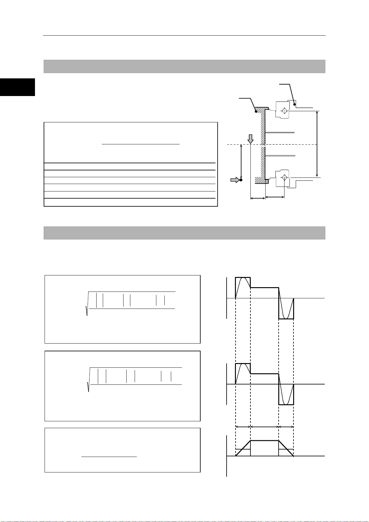
2-3 Verifying and examining load weights
Selection guidelines
Formula (1): Maximum load moment load
1000
Lamax FaR)(Lrmax
Fr
max
M
⋅++⋅
=
Mmax
Maximum load moment load
Nm
Frmax
Max. radial load
N
Refer to Fig.1.
Famax
Max. axial load
N
Refer to Fig.1.
Lr ,La
mm
Refer to Fig.1.
R
Offset amount
mm
Refer to Fig.1 an d Table 1.
Formula (2): Average radial load (Frav)
nn
10/3
nnn
10/310/3
10/3
tntntn
FrtnFrtnFrtn
Fr
2211
222111
+++
+
=
av
Formula (3): Average axial load (Faav)
nn
10/3
nnn
10/310/3
10/3
tnt
ntn
FatnFatnFatn
Fa
2
211
222111
+++
+
=
av
Formula (4): Average output rotational speed
n
nn
ttt
tntntn
N
21
2211
+++
+++
=
av
Time
+ Radial load -
Fr
Fr
Fr
Time
+ Axial load -
Fa
Fa
Fa
Time
+ Output rotational speed -
n
n
n
t
t
t
Fig. 2: Illustration of load variation
Fr
Fa
La
Lr
R
Load
dp
Fig. 1: External load action
Actuator
Maximum load moment load
The formula below sho ws how to calculate the m aximum load
moment load (Mmax).
Verify that the maximum load moment load (Mmax) is less than
or equal to the allowable load (Mc).
◆
Symbols used in the formula
――――
Verifying life
Calculating average loads (average radial and axial loads, average output rotational speed)
When the radial and/ or axial loads vary durin g motion, calculate a nd verify the life of the c ross roller
bearing converting the loads to their average values.
◆
The maximum radial load in section t1 is given by Fr1,
while the maximum radial load in section t
.
Fr
3
◆
The maximum axial load in section t
while the maximum axial load in section t3 is given by
.
Fa
3
◆
(Nav)
is given by
3
is given by Fa1,
1
1
2
3
1
2
3
1
1
2
2
3
3
77
Page 78

2-3 Verifying and examining load weights
1
2
3
4
5
6
7
8
9
10
11
付
Selection guidelines
Formula (5)
Y
5.1
La)/dpFaR)(Lr2(FrFr
Fa
≤
⋅+++
avavav
av
1.5
La)/dpFaR)(Lr2(FrFr
Fa
>
⋅+++
avavav
av
Symbols used in the formulas
Frav
Average radial load
N
Refer to the average load.
Faav
Average axial load
N
Refer to the average load.
Lr ,La
mm
Refer to Fig.1.
R
Offset amount
mm
Refer to Fig.1 a n d Table 1.
dp
Pitch circle diameter of a roller
mm
Refer to Fig.1 a n d Table 1.
Formula (7): Cross roller bearing life
10/3
6
10B
Pcfw
C
N60
10
L
⋅
×
×
=
−
av
L
B-10
Life
hour
―
Average output rotational
speed
C
Basic dynamic rated load
N
Refer to Table 1.
Dynamic equivalent radial
load
fw
Load coefficient
Refer to Table 3.
Formula (6): Dynamic equivalent radial load
av
avav
av
FaY
dp
La)FaR)(Lr2(Fr
FrXPc ⋅+
⋅++
+⋅=
Dynamic equivalent radial
load
Frav
Average radial load
N
Obtained by formula (2).
Faav
Average axial load
N
Obtained by formula (3).
Pitch circle diameter of a
roller
X
Radial load coefficient
Refer to Table 2.
Y
Axial load coefficient
Refer to Table 2.
Lr,La
mm
Refer to Fig.1.
R
Offset amount
mm
Refer to Fi g.1 and Table 1.
Table 3: Load coefficient
Loaded state
fw
Smooth operation free
from impact/vibration
Normal operation
1.2 to 1.5
Operation subject to
impact/vibration
Radial load coefficient and axial load coefficient
Determine the values of r adial load co eff icient (X) and axial lo ad coeff icient ( Y) based on the co ndition
below.
Table 2: Radial load coefficient (X), axial load coefficient (Y)
◆
――――
X
1 0.45
0.67 0.67
Dynamic equivalent radial load
◆
Symbols used in the formulas
Pc
dp
Life of cross roller bearing
Calculate the life of cross roller bearing with the formula (7):
◆
Symbols used in the formulas
N
mm Refer to Table 1.
-
-
-
Nav
Pc
r/min
N
-
Obtained by formula (4).
1 to 1.2
Obtained by formula (6).
1.5 to 3
78
Page 79

2-3 Verifying and examining load weights
Selection guidelines
Formula (8): Cross roller bearing life (oscillating)
10/3
6
Pcfw
C90
n60
10
Loc
1
⋅
×
θ
×
×
=
Loc
Life
hour
―
Number of reciprocating
oscillation per min.
C
Basic dynamic rated load
N
Refer to Table 1.
Pc
Dynamic equivalent radial load
N
Obtained by formula (6).
fw
Load coefficient
Refer to Table 3.
oscillating angle/2
Refer to Fig.3.
Formula (10): Static safety coefficient
Po
Co
fs =
fs
Static safety coefficient
Refer to Table 4.
Co
Basic static rated load
N
Refer to Table 1.
Po
Static equivalent radial load
N
Obtained by formula (9).
Formula (9): Static equivalent radial load
ma x
ma x
ma x
Fa44.0
dp
2M
FrPo ++=
Frmax
Max. radial load
N
Refer to Fig.1.
Famax
Max. axial load
N
Refer to Fig.1.
Refer to the
methods.
dp
Pitch circle diameter of a roller
mm
Refer to Table 1.
Table 4: Static safety coefficients
Using conditions
fs
High rotational accuracy
is required, etc.
Operation subject to
impact/vibration
Normal operation
1.5
Oscillating
Fig. 3: Oscillating movement
Cross roller bearing life with oscillating motion
Use formula (8) to calculate the cross roller bearing life against oscillating movement.
◆
Symbols used in the formulas
n1
θ
cpm ―
-
-
θ
angle
If the oscillating angle is 5° or less, fretting wear may occur because the oil film does not form
effectively on the contact s ur f ac es bet wee n th e r ace and rolling elements of the c r oss r oller b eari ng. In
such cases, consult with our engineering staff.
Verifying static safety coefficients
Static equivalent radial load
◆
Symbols used in the formulas
Mmax Max. moment load Nm
Static safety coefficient
Generally, the static equivalent load is lim ited b y the basic static rat ed load( Co). Ho wever, the specific
limit should be calculated according to the using conditions and required conditions. In this case,
calculate the static safety coefficient (fs) by formula (10).
Table 4 shows gener a l valu es r epres e nti ng us in g co nditions. Calculate the s tatic e quivalent radial load
(Po) by formula (9).
◆
Symbols used in the formulas
-
maximum load
weight calculation
≧3
≧2
≧
79
Page 80

2-4 Examining operating conditions
1
2
3
4
5
6
7
8
9
10
11
付
Selection guidelines
100
1000
3000
30
300
1
10
30
3
100r/min
70r/min
50r/min
35r/min
Linear travel speed (mm/min)
Screw pitch (mm)
Rotation speed (r/min)
20r/min
500r/min
(mm) pitch feedScrew
(mm/min) speed travel Linear
(r/min) speed Rotation =
2-4 Examining operating conditions
The actuator generates heat if started/stopped repeatedly or operated continuously at high speed.
Accordingly, examine whether or not the generated heat can be accommodated.
The study is as follows:
Calculate the actuator rotation speed
Calculate the required rotation speed (rpm) of the load driven by the SHA series.
For linear operation, use the rotation speed conversion formula below:
Select an appropriate reduction ratio so that the calculated rotation speed does not exceed the
maximum rotational speed of the SHA series actuator.
Calculating and examining load moment of inertia
Calculate the load inertia moment of the load driven by the SHA series actuator.
Refer to [A-2 Calculating moment of inertia ] (P103) for the calculation.
Based on the calculated result, tentatively select an SHA actuator by referring to [Allowable load
moment of inertia ] (P71).
80
Page 81

2-4 Examining operating conditions
Selection guidelines
Mass: W
Pitch: P
Friction: μ
π×
××
µ×=
2
P
W8.9
T
π×
××=
2
P
W8.9T
Pitch: P
Mass: W
r
W8
.9
T
××
µ×
=
Radius: r
Mass: W
Friction: μ
Example of rotary torque calculation (friction coefficient = 0.1)
10
1000
3000
100
Mass W (kg)
10
100
1000
Radius r of friction side (mm)
10000
15 Nm
20 Nm
SHA25A51
SHA65A81
SHA40A51
SHA32A51
30 Nm
40 Nm
50 Nm
200 Nm
300 Nm
10 Nm
500 Nm
600 Nm
700 Nm
800 Nm
5 Nm
Load torque calculation
Calculate the load torque as follows:
Rotary motion
The rotary torque for t he rotating m ass W on the r ing
of radius r from the center of rotation is shown in the
figure to the right.
T : Rotary torque (Nm)
μ : Friction coefficient
W : Mass (kg)
r : Average radius of friction side (m)
The right graph gives a calculation example
when the friction coefficient μ is assumed as 0.1
and the horizontal axis and vertical axis
represent mass and rotational radius of friction
side, respectively. The actuator toque value
shown in the graph indicates 20% of the
maximum torque.
SHA: 20% torque of maximum torque is shown.
Linear operation (horizontal operation)
The rotary torque when the mass W moves horizontally due to the screw of pitch P is shown below.
T : Rotary torque (Nm)
μ : friction coefficient
W : mass (kg)
P : Screw feed pitch (m)
Linear operation (vertical operation)
The rotary torque when the mass W moves vertically due to the screw of pitch P is shown below.
81
Page 82

2-4 Examining operating conditions
1
2
3
4
5
6
7
8
9
10
11
付
Selection guidelines
ta
td N Time
Rotation speed
(
)
LM
LA
a
T
T
N
60
π2
J
J
kt
−
×
×
×+
×
=
( )
LFM
LA
d
TT2T
N
60
π2
J
Jkt
+×+
×
×
×
+
×=
Acceleration and dece le ration time
Calculate acceleration and deceleration times for the selected actuator.
Acceleration time:
Deceleration time:
t
a: Acceleration time (s)
d: Deceleration time (s)
t
k: Acceleration reduction coefficient 1 to 1.5
The total positioning time may become shor t er
if the acceleration is lowered for the purpose
of reducing the settling time after positioning.
A: Actuator inertia moment (kg・m
J
L: Load inertia moment (kg・m
J
N: Actuator rotation speed (r/min)
M: Maximum actuator torque (Nm)
T
F: Actuator friction torque (Nm)
T
TF=KT x IR-TR
KT: Torque constant (Nm/A)
R: Allowable continuous torque (Nm)
T
R: Allow abl e conti nuou s curre nt (A)
I
T
L: Load torque (Nm); The polarity is positive (+) when the torque is applied in the rotation direction, or
negative (-) when it is applied in the opposite direction.
2
)
2
)
Calculation example 1
Select an actuator that best suits the following operating conditions:
・Rotation speed: 80 rpm
・Load inertia moment: 1.5 kg・m
・Since the load mechanism is mainly inertia, the load torque is negligibly small.
(1) After applying these conditions to the graph in [2-1], SHA25A51SG-B09A200 is tentatively
selected.
(2) From the rated table, the following values ar e obtained: J
41 Nm, K
(3) Based on the ab ove form ula, the ac tuator's friction torque T
Nm.
(4) If k = 1.3, the acceleration time and deceleration time can be obtained as follows from the
above formulas:
t
t
(5) If the calculated acceleration/deceleration times are too long, correct the situation by:
・Reducing load inertia moment
・Selecting an actuator with a larger frame size
T = 19 Nm/A, IR = 3A.
a = 1.3 x (0.56+1.5) x 2 x π/60 x 80/127 = 0.177 s
d = 1.3 x (0.56+1.5) x 2 x π/60 x 80/(127+2 x 16) = 0.141 s
2
A = 0.56 kg・m
F is calcu lated as 19 x 3 - 41 = 16
2
, TM = 127 Nm, TR =
82
Page 83

2-4 Examining operating conditions
Selection guidelines
Time
ta
td N tr
Time
Rotation speed
t: Cycle time
ts
Ta
Torque
Td
Tr
ts: Stopped time
Ta, Tr, Td: Output torques
t
tTtTtT
T
d
2
dr
2
ra
2
a
m
×+×+×
=
t
t2NtNt
2N
N
dra
av
×+×+×
=
Nm 53
1
0. 141900. 09100. 17798
T
222
m
=
×+×+×
=
r / mi n20
1
0. 1412800. 091800. 177280
N
av
=
×+×+×
=
Examining effec tive torque and average rotation speed
One way to check if the heat ge nerated f rom the ac tuator dur ing oper atio n would present a prob lem is
to determine if the point of operat ion, determ ined by the effective torque and av erage rotation spe ed,
is inside the continuous motion range explained in [1-14 Operable range].
Using the following formula, calculate the eff ective torque T
the actuator is operated repeatedly in the drive pattern shown to the right.
ta : Acce lerat ion t ime fro m spee d 0 to N (s)
d : Deceleration time from speed N to 0 (s)
t
t
r : Operation time at constant speed N (s)
t : Cycle time (s)
T
m : Effective torque (Nm)
a : Torque during acceleration (Nm)
T
r : Torque at constant speed (Nm)
T
Td : Torque during deceleration (Nm)
av : Average rotation speed (rpm)
N
N : Rotation speed at constant speed (rpm)
Calculation example 2
An example of SHA25A51SG-B09A200 is explained.
Operating conditions: Accelerate an inertia load and then let it move at a constant speed,
followed by deceleration, based on conditions similar to those used in calculation example 1.
The travel angle per cycle is 120° and the cycle time is 1 second.
(1) T he travel angle is calculated from the area of the rotation speed vs. time diagram shown
above. In other words, the travel angle is calculated as follows:
θ = (N / 60) x {t
Accordingly, t
When θ= 120°, and t
are applied to this formula, t
(2) N ext, calculate the tor que during ac celeration an d torque during dec eleration. B ased on the
acceleration/decelerat ion time formulas in the preceding section, the r elational expressions
for torque during acceleration and torque during deceleration if k = 1 are as follows:
a = (Ja+JL) x 2 xπ / 60 x N / ta + TL
T
T
d = (Ja+JL) x 2 xπ / 60 x N / td – 2 xTF – TL
When the values in calcula t ion example 1 are applied to this form ula, T
90 (Nm) are obtained.
(3) C alculate the effective torque. Appl y the values in ( 1) and ( 2), a nd T
to the above formulas.
(4) Calculate the average rotation speed. Apply the values in (1), and N = 80 (rpm) and t = 1 (s),
to the above formulas.
r + (ta + td) / 2} x 360
r = θ/ (6 x N) – (ta + td) / 2
a = 0.177 (s), td = 0.141 (s), N = 80 (rpm) in calculation exam ple 1,
r is calculated as 0.091 (s).
m and average r otation speed Nav when
a = 98 (Nm) and Td =
r = 0 (Nm) and t = 1 (s ),
83
Page 84

2-4 Examining operating conditions
1
2
3
4
5
6
7
8
9
10
11
付
Selection guidelines
2
222
m
ddrr
aa
T
t
Tt
TtT
t
×
+
×+×
=
放熱板:350*350*18
0
25
50
75
100
125
150
0 20 40
60 80 100 120
回転速度 [r/min]
トルク [Nm]
加減速運転領域
連続使用領域
50%デューティ領域
Operable range of SHA25A51
Radiation plate: 350*350*18
Motion range during
acceleration and
deceleration
50% duty motion range
Continuous
Torque [Nm]
Rotation speed [rpm]
(5) T he figure on the right sho ws the point of operation determ ined by the effective torque and
average rotation speed calculated above, plotted on the graph of operable range of
SHA25A51, exceeding the continuous motion range. The conclusion is that this actuator
cannot be operated continuously under these conditions. Accordingly,
◆the operation pattern
◆load (possible reduction)
◆actuator model number.
etc., must be reexamined.
The following formula is a modified
version of the formula for effective torque.
By applying the value of allowable
continuous torque to Tm in this formula,
the allowable cycle time can be calculated.
★
motion range
Apply the following:T
d = 0.141 s Then, t he f ollowing equation is obtained:
t
t = (98
Based on the result, setting the cycle tim e to 1.7 seconds or more to provide a longer stopped
time gives T
continuous torque.
2
x 0.177 + 902 x 0.141)/ 412 = 1.69 s
m = 41 Nm or less, thereby permitting continuous operation within the allowable
a = 98 Nm, Tr = 0 Nm, Td = 90 Nm, Tm =41 Nm, ta = 0.177 s , tr = 0.091 s,
The aforementione d continuous duty range represents an al lowable range when the
actuator is installed on the spec if ied a luminum heatsink and operated under natural air
cooling. If the radiatio n are a of t he mounting member is smaller or the he at c ond u c tion
of the material is poor, adjust the operating con ditions to lim it the temperatur e rise of
the actuator to 40º C or less as a guide.
84
Page 85

Chapter 3
Installing the SHA actuator
The following explains the installation procedures of the actuators.
3-1 Receiving Inspection ······························································ 86
3-2 Notices on handling ······························································· 87
3-3 Location and installation ························································· 91
Page 86

3-1 Receiving Inspection
1
2
3
4
5
6
7
8
9
10
11
付
Installing the SHA actuator
WARNING
3-1 Receiving Inspect ion
Check the following items after unpacking the package.
Inspection procedure
1 Check the items thoroughly for damage sustained during transportation.
If any item is damaged, immediately contact the dealer.
2 Confirm the actuator is what you ordered.
The nameplate is found on the rear end face of the SHA series actuator. Check the TYPE field
on the nameplate t o confirm that it is in deed the m odel you have ordered. If any item is wro ng,
immediately contact the dealer.
Refer to the section 1-2 in this manual for the detail of the model codes.
3 Check driver input voltages.
The driver's model cod e is shown in the TYPE field of the dr iver's nameplate. The last thr ee
digits of this model code indicate the input voltage to be input.
100: indicates a single phase 100VAC power supply.
200: indicates a 3-phase/single-phase 200VAC power supply.
If the voltage to be supplie d is different from the lab el voltage, imm ediately contact the de aler it
was purchased from.
Do not connect a supply voltage other than the voltage specified
on the driver label.
The wrong power supply voltage may damage the driver, resulting in physical
injury or fire.
86
Page 87

3-2 Notices on handling
Installing the SHA actuator
CAUTION
Machine base
Output structure
Output
Machine base
flat
3-2 Notices on handli ng
Handle the SHA series actuator carefully by observing the notices specified below.
(2) Do not put the SHA series actuator on a table, shelf, etc., where the
(3) Do not connect the actuator terminals directly to the power supply. The
(4) The allowable storage temperature is -20 to +60℃. Do not expose the
(5) The allow able relative storage humidity is 80% or les s. Do not store the
(6) Do not use or store the actuator in locations subject to flammable or
(7) The large models (SHA58A, SHA65A) are heavy. Handling these models
(1) Do not apply any excessive force or impact, especially to the actuator's
output shaft.
actuator could easily fall.
actuator may burn and cause fire or electric shock.
actuator to direct sunlight for long periods of time or store it in areas in
low or high temperature.
actuator in a very humid p lace or in areas w h ere temperatu res a re lik e l y t o
fluctuate greatly during day and night.
corrosive gases or dust particles.
may cause lower ba ck pain. Injury may occur if the actuator falls and you
are pinned underneath. Handle your actuator with due care by wearing
safety shoes or take other proper precautions. Use supporting fixtures
and lifting equipment as necessary for safe handling.
Installation and transmission torque
Examples of actuator assembly are shown below. Assembly examples 1 and 2 are for SHA-SG.
Assembly examples 3 and 4 are for SHA-CG. Use high-tension b olts and tighten them with a torque
wrench to control the tightening torque. In assembly example 2, use flat washers because the
tightening torque is high and the actuator flange is made of aluminum.
SHA-SG assembly example
structure
Washer
Assembly example 1 Assembly example 2
87
Page 88

1
2
3
4
5
6
7
8
9
10
11
付
Installing the SHA actuator
SHA-CG assembly example
Output
shaft
Output
shaft
Output
shaft
16-M4
12-M4)
16-M5
12-M5)
Bolt
P.C.D.
4.5
3.2)
9
6.4)
0.46
0.33)
0.92
0.65)
433
325)
430
381)
900
675)
891
754)
44
33.2)
44
38.9)
92
68.9)
91
76.9)
SHA40A
SHA58A
SHA65A
Output
shaft
Output
shaft
Output
shaft
Number of bolts, size
16-M6
12-M6
12-M10
16-M8
16-M10
16-M10
Bolt
P.C.D.
Tightening
torque
Nm
15.3
15.3
74
37
74
74
kgf・m
1.56
1.56
7.5
3.8
7.5
7.5
Transmission
torque
Nm
1560
1510
4940
5230
7210
9550
kgf・m
159
154
504
533
735
974
Actuator fixing parts
Actuator fixing parts
Output shaft fixing parts
Output shaft fixing parts
Assembly example 3
Recommended tightening torque and transmission torque
SG/HP type
Model
Item
SHA20A SHA25A SHA32A
Actuator
Actuator
3-2 Notices on handling
Actuator
Number of bolts, size 16-M3 12-M3
installation
Tightening
torque
Transmission
torque
The values in parenthesis are those combined with the HPF hollow shaft planetary speed reducer.
mm 62 84 77
Nm 2.0 2.0 4.5
kgf・m
Nm 203 206
kgf・m
0.20 0.20 0.46
21 21
(
(
(
12-M4
102
(127)
(
(
(
(
(
(
(
100
9
0.92
12-M5
132
(157)
(
(
(
(
Model
Item
installation
Notes 1, 2
Note 3
mm 122 158 178 226 195 258
Actuator
Actuator
Actuator
88
Page 89

3-2 Notices on handling
Installing the SHA actuator
SHA20A
SHA25A
Output
shaft
Output
shaft
Number of bolts, size
12-M4
6-M5
12-M5
8-M6
Bolt
P.C.D.
Tightening
torque
Nm
4.5
6.4 9 11
kgf・m
0.46
0.65
0.92
1.1
Transmission
torque
Nm
253
257
486
600
kgf・m
26
26
50
61
SHA32A
SHA40A
Output
shaft
Output
shaft
Number of bolts, size
12-M6
12-M6
12-M8
8-M10
Bolt
P.C.D.
Tightening
torque
Nm
15.3
11
37
52
kgf・m
Transmission
torque
Nm
918
1114
2012
2639
kgf・m
94
114
205
269
CG type
Model
Item
Actuator
Actuator
installation
Notes 1, 2
Note 3
mm 60 107 72 131
Model
Item
installation
Notes 1, 2
mm 96 162 116 203
1.6 1.1 3.8 5.3
Note 3
Actuator
Actuator
Note 1) The female thread material is premis ed to withstand the bolt tightening torque
2) Recommended bolt: Hexagonal bolt per JIS B 1176 Intensity category: JIS B 1051 12.9 or higher
3) Calculation conditions Torque efficiency: 0.2 Tightening efficiency: 1.4 Tightening friction coefficient:
0.15
Precautions on installation
When designing the assembly, take note that application of any abnormal or excessive force that
causes deformation of the installation surface may result in performance drop. To demonstrate the
excellent performance of the SHA series actuator fully, take note of the following points:
Warping or deformation on the machine mounting surfaces
Foreign matter on the mounting surfaces
Raised burrs or deformation around the tapped mounting holes
Insufficient chamfering of mounting pilot diameter
Mounting pilot diameter is out-of-round
When the installation method is as shown in assembly example 2
mentioned above, th e recessing shown to the righ t is recommended
for the spigot corner section on the actuator fixing member.
89
Page 90

3-2 Notices on handling
1
2
3
4
5
6
7
8
9
10
11
付
Installing the SHA actuator
Location
Surface treatments
Housing
No treatment (aluminum material is exposed)
Output shaft bearing
Raydent
Speed reducer rotating part
Chrome plating
Output flange
Nickel plating Raydent
Hollow shaft (sleeve)
Nickel plating
Bolt
Chrome plating
Location
Surface treatments
Housing
No treatment (aluminum material is exposed)
Output flange
Raydent treatment
Speed reducer rotating part
Raydent treatment, enamel resin is applied to some
surfaces
Hollow shaft (sleeve)
Nickel plating
Bolt
Chrome plating or Nickel plating
Output structure
Machine Base
Positioning pin*2
Positioning pin*2
Example of use of positioning pins
*1
Use of positioning pins
The SHA series SG type actuator has posi tioning pin holes in the output rotary u nit and flang e fixed t o
the actuator. The SHA series CG type has positioning pin holes only in the output rotary unit.
Use these pins as necessary. For details, refer to [1-6 External dimensions] (P1-11) or the illustrated
specifications.
*1. Do not drive positioning pins into the output rotary unit, but keep proper fitting clearances to the
actuator parts. Failur e to do so may result in lower positional accuracy.
*2. The hollow shaft planetary speed reducer model is not equipped with a positioning pin.
Surface treatments
Standard SHA series actuators are given the following surface treatments:
SG/HP type
CG type
The surface treatments given to SHA series actuators do not fully prevent rust.
90
Page 91
3-3 Location and installation
Installing the SHA actuator
The protection class against contact and entry of foreign
The protection class against water entry is as follows:
4: Protected against water splashed from all directions.
3-3 Location and i nstallation
Operating Environment
The environmental condit ions of the installation locati on for SHA series actuators must be as f ollows.
Select an appropriate installation locat io n and observe these conditions without fail.
◆ Operating temperature: 0 to 40℃
The temperature in the cabinet may be higher than the atmosphere depending on
the power loss of housed devices and size of the cabinet. Plan the cabinet size,
cooling system, and device locations so the ambient temperature of the actuator is
kept 40℃ or below.
◆ Operating humidity: Relative humidity of 20 to 80%.
Make sure no condensation occurs. Take note that condensation is likely to occur in
a place where there is a large temperature change between day and night or when
the actuator is started/stopped frequently.
2
◆ Vibration: 25 m/s
◆ Impact: 300 m/s
◆ Use environment: Free from condensation, metal powder, corrosive gase s, water, oil mist, f lammable
gases, etc.
(10 to 400Hz) or less (Refer to [1-13 Vibration resistance ] (P52))
2
or less (Refer to [1-12 Shock resistance] (P51))
◆ Protection class: Standard products are structurally desig ned to meet the
IP-54 requirements.
matter is as follows:
5: Protected against entry of dust/dirt. Entry of water or
foreign matter caused by incomplete protection must not
affect the operation of the system.
However, rotating and sliding areas (oil seal areas) and connectors of SHA20, 25, 32 and 40 are
not IP-54-compliant. Connectors of SHA58 and 65 are protected in fitted conditions.
◆ Locate the driver indoors or within an enclosure. Do not expose it to the sunlight.
◆ Altitude: lower than 1,000 m above sea level
◆ The oil seals in rotating and sliding areas do not fully prevent leakage of lubricant. If the actuator is used in a
clean room, etc., provide additional oil leakage prevention measures.
91
Page 92

3-3 Location and installation
1
2
3
4
5
6
7
8
9
10
11
付
Installing the SHA actuator
Output
shaft
Flange
WARNING
Installation
The SHA series actuator drives mechanical load system at high accuracy.
When installing the actu ator, pay attention to precision and do not tap the actuat or output part with a
hammer, etc. The actuator houses an encoder. Excessive impact may damage the encoder.
Installation procedure
1 Align the axis of rotation of the actuator and the
load mechanism precisely.
Note 1: Perform this alignment carefully, especially when
a rigid coupling is used. Even slight
misalignment may cause the permissible load of
the actuator to be exceeded, resulting in
damage to the output shaft.
2 Connect the driver and wiring.
An extension cable is prov i ded. Us e i t when wir i ng th e drive r. For details on wiring, r ef er to [1-15
Cable specifications].
3 Wire the motor cable and encoder cable.
Do not pull the cables with a strong force. T he connection poi nts may be damaged. Ins tall the
cable with slack not to apply tens ion to th e actuat or. Provide a sufficient bending radi us (at leas t
6 times the cable diameter), especially when the cable flexes.
Do not bring strong m agnetic objects (magnet chuc ks, permanent m agnets, etc.) near
the rear cover of the actuator. Encoder abnormality may result.
This encoder retains absol ute positions when the p ower is turned OFF b y means of
the driver's battery or its own built-in capacitor. If the encoder cable is disconnected for
maintenance, etc., turn on the driver power and charge the backup capacitor first.
After 3 hours of charge, the encoder cable can be disconnected for 30 minutes,
provided that the axis is stopped and ambient temperature is 25℃. However, when the
Do not disassemble/reassemble the actuator.
May cause damage to electrical and mechanical components.
backup capacitor is deteriorated, the absolute positions may not be retained.
92
Page 93

Chapter 4
Options
This chapter explains the options available for the SHA series actuator.
4-1 Options ··············································································· 94
Page 94

Options
1
2
3
4
Apx
6
7
8
9
10
11
付
Appendix
4-1 Options
Origin and end limit sensors (option code: L)
This option includes s ens ors that are directly connecte d to the ou tput s haft on th e rear of the actuato r.
Use this option if a mechanical origin is required (when the virtu al or igin of the a bsolut e enco der is no t
sufficient) or you want to define an operation range as a safety measure. SHA20A is not compatible.
Option for side exit cables (option code: Y)
This option allows the motor and encoder cables te exit from the side of the actuator.
Use this option if the ac tuat or is ho used in a s ystem and ther e is not e nough r oo m for c ables to exit at
the rear of the housing.
This option is not available with the SHA20 (SG type), SHA58 and SHA65.
Contact us for details.
Output shaft single revolution absolute model (opt ion cod e: S)
With the standard encoder, when it continues to rotate in just one direction, the absolute encoder
eventually exceeds the nu mber of revolutions that can be detected with multi-revo lution detection an d
it becomes impossible to manage position information accurately.
With the output shaft singl e revolut ion abso lute model, each tim e the output s haft turns through si ngle
revolution, the cum ulative multi revolution counter is cleared to 0. This is how position inf ormation is
accurately managed when the shaft continuousl y turns in just one direction. To use this function, it is
necessary to setup a driver. Refer to "HA-800 Series AC Servo Driver Manual". This model is
compatible with CG type only.
Stand (CG type only)
A stand is available for purchase to use the CG type for table drive. For details, contact our sales office.
94
Page 95

Options
Appendix
Nameplate
●Outline drawing of the actuator with an optional stand
95
Page 96

1
2
3
4
Apx
6
7
8
9
10
11
付
Appendix
Item
Unit
SHA20
SHA25
SHA32
SHA40
a
mm
69 h7 0/-0.030
84 h7 0/-0.035
1 10 h7 0/-0.035
132 h7 0/-0.040
b
mm φ135 φ160 φ198 φ248
c
mm
143 φ168 φ208 φ258
d
mm
177 h7 0/-0.040
210 h7 0/-0.046
260 h7 0/-0.052
316 h7 0/-0.057
e
mm
133±0.3
135.5±0.3
152±0.3
180±0.3
f
mm
118
120
133
163
g
mm
7.5 8 8
10
h
mm
11
13
13
20
6-φ6.6
13 depth 1
j
mm
161 φ190 φ234 φ288
k - 12-M4×7
12-M5×8
12-M6×10
12-M8×12
m
mm
60 φ72 φ96 φ116
n
mm
170
160
150
130
o
Note1)
mm
0.050
0.055
0.060
0.070
p
Note1)
mm
0.080
0.080
0.090
0.100
r °
60
22.5
45
90
s
mm
107 φ131 φ162 φ203
t
mm
2-M6 depth 11
2-M8 depth 13
2-M8 depth 15
2-M12 depth 23
Mass
Note2)
kg
4.4(4.5)
6.1(6.2)
11.6(11.9)
20(21)
Section i
Note 5
:
Bolts used
Section i
torque
●Dimensions and installation specifications of the actuator with an optional stand
Options
i mm
Recommended
tightening
φ
φ
φ
counterbore
φ
φ
φ
φ
φ
- 6-M6 6-M8 6-M10 6-M12
Nm 11 26 52 90
φ
φ
6-φ9 counterbore
φ17 depth 1
φ
φ
φ
6-φ11 counterbore
φ21 depth 1
φ
φ
φ
6-φ13 counterbore
φ25 depth 1
φ
Note 1) All values are T.I.R. (Total Indicator Reading).
2) The values in parentheses are for models with a brake.
3) For detailed dimensions and specifications of the actuator, refer to the illustrated specifications.
4) Cast aluminum is used for the material of the stand. No surface treatment has been applied.
5) Use flat washers when installing the product.
96
Page 97

Options
Appendix
Cable length
(Unit: mm)
Outer diameter φ7.8
Cable length (03 = 3m, 05 = 5m, 10 = 10m)
Cable length (03 = 3m, 05 = 5m, 10 = 10m)
[Driver side]
[Actuator side]
Brake: blue
Brake: yellow
PE: green/yellow
W: black
V: white
U: red
Solder processing
Cable length
(Unit: mm)
[Driver side]
Solder processing
Brake: blue
Brake: yellow
PE: green/yellow
Wiring display seal
W: black
V: white
U: red
[Actuator side]
(SHA20A∙25A∙32A∙40A)
Outer diameter φ7.8
Extension cables
These extension cables are used to connect the SHA series actuators and HA-800 drivers.
Two types of extension cables are available for motor (including brake wire) and absolute encoder.
You must use an extension cable to connect your SHA series actuator and
HA-800 driver.
Motor extension cable:
SHA 20, 25, 32, 40 (Size 40 requires an extension cable when combined with the
HA-800-6D/E.)
EWD-MB**-A06-TN3
(** in the model code indicates the cable length (03 = 3m, 05 = 5m, 10 = 10m).)
SHA 40 (when combined with the HA-800-24D/E)
EWD-MB**-A06-TMC
97
Page 98

1
2
3
4
Apx
6
7
8
9
10
11
付
Appendix
SHA 58, 65
Cable length (03 = 3m, 05 = 5m, 10 = 10m)
Cable length
Outer diameter φ13.4
(Unit: mm)
[Actuator side]
[Driver side]
U: red
V: white
W: Black
PE: green/yellow
Brake: blue
Brake: yellow
Waterproof cable clamp
Angle plug
EWD-MB**-D09-TMC
Options
98
Page 99

Options
Appendix
Cable length
(Unit: mm)
Outer diameter φ8.4
Cable length (03 = 3m, 05 = 5m, 10 = 10m)
Cable length (03 = 3m, 05 = 5m, 10 = 10m)
Cable length
Outer diameter φ8.4
(Unit: mm)
[Actuator side]
[Driver side]
[Actuator side]
[Driver side]
Absolute encoder extension cable:
SHA 20, 25, 32, 40
EWD-S**-A08-3M14
(** in the model code indicates the cable length (3m, 5m, 10m).
SHA 58, 65
EWD-S**-D10-3M14
99
Page 100

1
2
3
4
Apx
6
7
8
9
10
11
付
Appendix
Appendix
Unit conversion··································································· 101
A-1
A-2 Calculating inertia moment ···················································· 103
Options
100
 Loading...