

Page 1
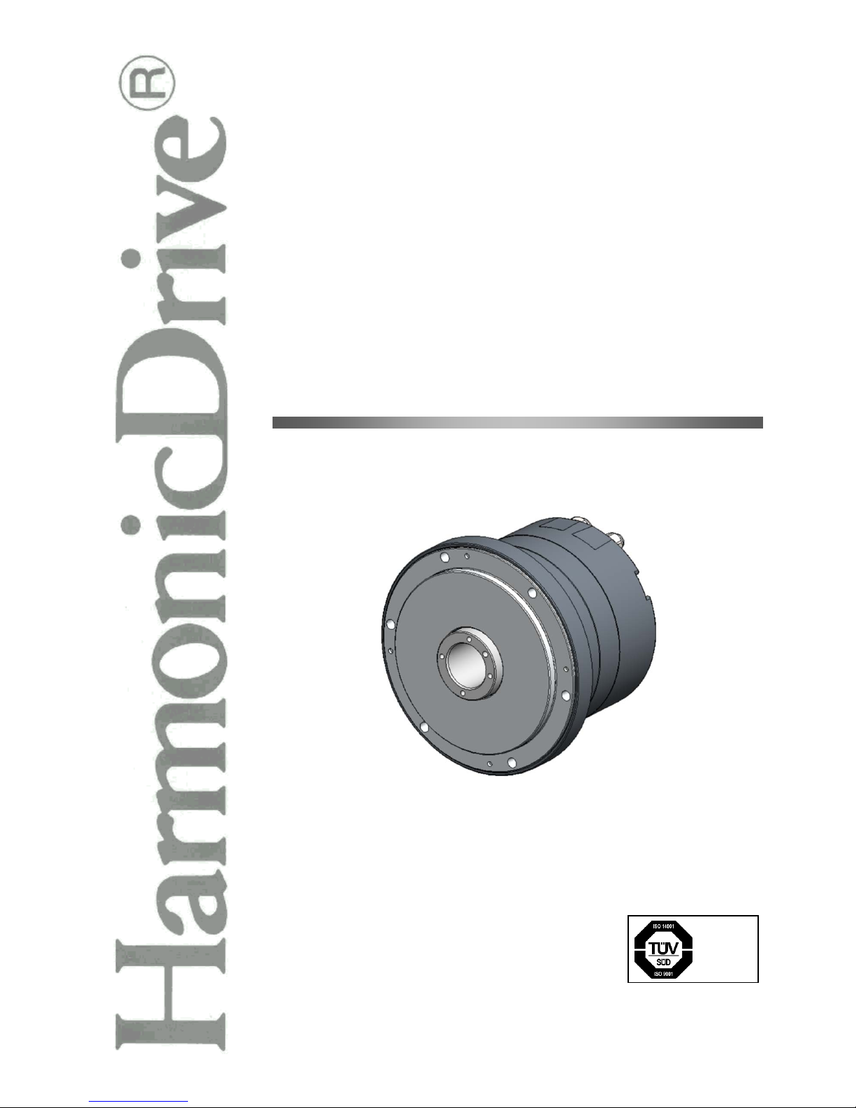
Flat Hollow Shaft AC Servo Motors
HMA s eries m anual
ISO14001
ISO9001
Page 2

Introduction
Introduction
Thank you for purchasing our HMA series AC servo motor.
Incorrect handling or improper use of this product m ay result in unexpected accidents or a shorter
product life. Read t his manual caref ully and us e the pr oduct corr ectly s o that the product can be used
safely for many years.
The information contained in this manual is subject to change without notice.
Keep this manual in a convenient location and refer to it whenever necessary in operating or
maintaining the product.
The end user of the product should have a copy of this manual.
Page 3
SAFETY GUIDE
1
SAFETY GUIDE
To use this product safely and cor rectly, be sure to read the SAF ETY GUIDE and other parts of this
document carefully and fully understand the information provided here in bef or e using the pr od uct .
NOTATION
Important safety information you must note is provided herein. Be sure to observe these instructions.
Indicates a potentiall y hazardous situatio n, which, if not avoi ded, could result
in death or serious personal injury.
Indicates a potentially hazardous situation, which, if not avoided, may result in
minor or moderate personal injury and/or damage to the equipment.
Indicates what should b e performed or avoided to prevent non-operation or
malfunction of the product or negative effects on its performance or function.
LIMIT ATION OF APPLICATIONS
The equipment listed in this document may not be used for the applications listed below:
・
Space equipment
・ Aircraft, aeronautic equipment
・ Nuclear equipment
・ Household apparatus
・ Vacuum equipment
・ Automobile, automotive parts
・ Amusement equipment, sport equipment, game machines
・ Machines or devices acting directly on the human body
・ Instruments or devices to transport or carry people
・
Apparatus or devices used in special environments
If the above list includes your intended application for our products, please consult us.
If this product is utilized in any facility in which human life is
at stake or that may incur material losses, install safety
devices so that accidents do not occur even when the output
control is disabled due to damage.
WARNING
CAUTION
CAUTION
Page 4
SAFETY GUIDE
2
SAFETY NOTE
ITEMS YOU SHOULD NOTE WHEN USING THE MOTOR
CAUTIONS RELATED TO THE DESIGN
Always use the motor under the specified conditions:
The motor is designed to be used indoors. Observe the following conditions:
・ Ambient temperature: 0 to 40℃
・ Ambient humidity: 20 to 80% RH (no condensation)
・ Vibration: Max. 25 m/s2
・ No contamination by water or oil
・ No corrosive or explosive gas
Always follow the instructions in the related manuals to
install the motor in the equipment.
・ Follow the instructions in th e manual t o ensure t hat th e center of the motor
is aligned with the center of the paired unit.
・ Improper alignment may cause vibration or damage to the output shaft.
OPERATIONAL PRECAUTIONS
Do not exceed the allowable torque.
・ Do not apply a torque exceeding the maximum torque.
・ Be aware that, if arms directly attached to the output shaft are hit, the output
shaft may become uncontrollable.
Never connect cables directly to a power supply socket.
・ Motors must be connected to the proper driver to operate.
・ Do not connect a comm ercial power supp ly directly to the motor. Failure to
observe this caution may damage the motor, possibly resulting in a fire.
Do not apply impacts and shocks to the motor.
・ Do not tap the motor with a hammer or other tool be cause an encoder is
connected directly to the motor.
・ If the encoder is damaged, the motor may become uncontrollable.
Do not pull the cables.
・ Pulling the cables can dam age connectors, causing the motor to bec ome
uncontrollable.
CAUTION
WARNING
Page 5
SAFETY GUIDE
3
ITEMS YOU SHOULD NOTE WHEN USING THE DRIVER
CAUTIONS RELATED TO THE DESIGN
Always use the motor under the specified conditions:
The driver generates heat. Take extra caution for radiation and use it under the
following conditions.
・ Mount in a vertical position keeping sufficient distance from other devices to
let heat generated by the driver radiate freely.
・ 0 to 50℃, 95% RH or below (No condensation)
・ No vibration or physical shock
・ No dust, dirt, corrosive, or explosive gas
Use sufficient noise suppressing means and safe grounding.
An y noise gener ated on a signa l wire ca uses vibra tion or improper motion. Be
sure to observe the following precautions.
・ Keep signal and power leads separated.
・ Keep leads as short as possible.
・ Ground the motor and driver at one single point, minimum ground
resistance class: D (less than 100 ohms)
・ Do not use a power line filter in the motor circuit.
Pay attention to negative torque caused by inverse load.
・ An inverse load may cause damage to the driver.
・ Please consult our sales office if you intent to use the motor in such
applications.
Use a fast-response type ground-fault detector designed for
PWM inverters.
When using a fast-response type ground-fault detector, use one that is
designed for PWM inverters. Do not use a time-delay-type ground-fault
detector.
If this product is utilized in any facility in which human life is
at stake or that may incur material losses, install safety
devices so that accidents do not occur even when the output
control is disabled due to damage.
OPERATIONAL PRECAUTIONS
Never change any wiring while the power is active.
Mak e s ure that th e po wer i s not ac ti ve bef or e ser vic in g the products. Failure t o
observe this caution may result in an electric shock or uncontrollable operation.
Do not touch the terminals for at least 5 minutes after turning
OFF the power supply.
・ Even after the power suppl y is turned OFF, electric charge remains in the
driver. In order to prevent electric shock, perform inspections 5 m inutes or
more after the power supply is turned OFF.
・ When installing, make sure that the inner electronic components are hard to
reach.
CAUTION
WARNING
Page 6

SAFETY GUIDE
4
Do not perform a voltage resistance test.
・ Do not perform a Megger t est or voltag e resistance t est. F ailure to obser ve
this caution may result in damage to the control circuit of the driver.
・ Please consult our sales office if you intent to perform such tests.
Do not operate the driver by switching the power ON/OFF.
・ Frequent power ON/OFF operations may cause deterioration of circuit
elements inside the driver.
・ Use command signals to start or stop the motor.
DISPOSAL
The motor and driver must be disposed of as industrial
waste.
W hen disposing of the motor or driver, disassemble it as much as poss ible,
separate parts acc ording to the m aterial des cription ( if indic ated), and dispos e
of them as industrial waste.
CAUTION
CAUTION
Page 7

5
Contents
SAFETY GUIDE .................................................................................................. 1
NOTATION ............................................................................................................. 1
LIMIT ATION OF APPLIC ATIONS ............................................................................ 1
SAFETY NOTE ...................................................................................................... 2
Contents .......................................................................................................... 5
Related manual .................................................................................................. 7
Conformance to overseas standards
......................................................................... 7
Chapter 1 Outlines
1-1 Outlines ...................................................................................................... 1-1
1-2 Model ....................................................................................................... 1-2
1-3 Combinations with drivers and extension cables.......................................... 1-3
1-4 Specifications ............................................................................................... 1-4
1-5 Holding brake ............................................................................................... 1-6
1-6 External dimensions ..................................................................................... 1-7
1-7 Mechanical accuracy .................................................................................. 1-12
1-8 Detector specifications (Absolute encoder) ................................................ 1-13
1-9 Rotation direction ....................................................................................... 1-14
1-10 Shock resistance ...................................................................................... 1-15
1-11 Resistance to vibration ............................................................................. 1-16
1-12 Operable range ........................................................................................ 1-17
1-13 Cable specifications ................................................................................. 1-20
Motor cable specifications ................................................................................. 1-20
Encoder cable specifications ............................................................................. 1-21
Chapter 2 Selection guidelines
2-1 HMA series selection .................................................................................... 2-1
Allowable load inertia moment ............................................................................. 2-1
2-2 Verifying and examining load weights .......................................................... 2-2
2-3 Examining the operating status .................................................................... 2-3
Examining motor rotational speed ....................................................................... 2-3
Calculating and examining load inertia moment ................................................... 2-3
Load torque calculation ....................................................................................... 2-4
Acceleration time and deceleration time .............................................................. 2-5
Evaluating effective torque and average rotational speed .................................... 2-6
Page 8

Contents
6
Chapter 3 Installing t he HMA motor
3-1 Receiving inspection .................................................................................... 3-1
Inspection procedure ........................................................................................... 3-1
3-2 Notices on handling ...................................................................................... 3-2
Installation and transmission torque .................................................................... 3-2
Precautions on installation ................................................................................... 3-3
Use of positioning pins ........................................................................................ 3-4
Motor shaft material ............................................................................................. 3-4
3-3 Location and installation ............................................................................... 3-5
Environment of location ....................................................................................... 3-5
Installation ........................................................................................................... 3-6
Chapter 4 Options
4-1 Options ...................................................................................................... 4-1
Cable taken out from side face (option code: Y) .................................................. 4-1
Extension cables ................................................................................................. 4-2
Appendix
A-1 Unit conversion ............................................................................................ 5-1
A-2 Calculating inertia moment .......................................................................... 5-3
Formulas of mass and inertia moment ................................................................. 5-3
Inertia moment of cylinder ................................................................................... 5-5
Page 9

Related manual
7
Related manual
The related manual is listed below. Use it as a reference as necessary.
Title
Description
AC Servo Driver
HA-800 series manual
The specifications and characteristics of HA-800 series driv er s are explained.
Conformance to overseas standards
The HMA series motors are compliant with the following overseas standards.
UL standards
UL1004-1, UL1004-6 (File No. E243316)
CSA standards
C22.2 No.100
European Low Voltage EC Directives
EN60034-1, EN60034-5
UL nameplate stick er
According to the UL10 04-1, UL1004-6 (File No. E243316) standards , the following spec ifications are
indicated on the HMA series motors.
Nameplate
field
Description
(1)
Output [W] at point A on the graph below
(2)
Voltage [V] between motor wires at point A on the
graph below
(3)
Allowable continuous current [A ]
(4)
Rotational speed at point A on the graph below [r/min]
(5)
Current fundamental frequency [Hz] at point A on the
graph below
(6)
Allowable ambient temperature [℃]
(7)
Number of phases
(1)
(2)
(3)
(4)
(5)
(6)
(7)
UL nameplate sticker
Rated torque
A
Motion range during
acceleration and deceleration
Aluminum radiation plate: 320*320*16
Continuous motion
range
Rotation speed [r/min]
Torque [Nm]
Page 10

Conformance to overseas standards
8
The values displayed on the name plate for each model are shown below.
Model
Item
HMAC08
(1) Output at point A
W
163
(2) Voltage at point A
V
130
(3) Allowable continuous current
A
2.1
(4) Speed at point A
r/min
3,000
(5) Frequency at point A
Hz
250
(6) Allowable ambient temperature
℃
40
(7) Number of phases
-
3
Model
Item
HMAB09
(Motor input voltage 200 V)
HMAB09
(Motor input voltage 100 V)
(1) Output at point A
W
251
251
(2) Voltage at point A
V
136
71
(3) Allowable continuous current
A
2.5
4.3
(4) Speed at point A
r/min
3,000
3,000
(5) Frequency at point A
Hz
250
250
(6) Allowable ambient temperature
℃
40
(7) Number of phases
-
3
Model
Item
HMAB12
(1) Output at point A
W
406
(2) Voltage at point A
V
129
(3) Allowable continuous current
A
4.2
(4) Speed at point A
r/min
2,500
(5) Frequency at point A
Hz
208
(6) Allowable ambient temperature
℃
40
(7) Number of phases
-
3
Model
Item
HMAB15
(1) Output at point A
W
754
(2) Voltage at point A
V
125
(3) Allowable continuous current
A
7.8
(4) Speed at point A
r/min
2,000
(5) Frequency at point A
Hz
167
(6) Allowable ambient temperature
℃
40
(7) Number of phases
-
3
Model
Item
HMAA21A
(1) Output at point A
W
1,320
(2) Voltage at point A
V
100
(3) Allowable continuous current
A
20.0
(4) Speed at point A
r/min
1,000
(5) Frequency at point A
Hz
133
(6) Allowable ambient temperature
℃
40
(7) Number of phases
-
3
Page 11

Page 12

Chapter 1
Outlines
This chapter explains the features, functions and specifications of the motor.
1-1
Outlines ············································································· 1-1
1-2 Model ················································································ 1-2
1-3 Combinations with drivers and extension cables ························· 1-3
1-4 Specifications ······································································ 1-4
1-5 Holding brake ······································································ 1-6
1-6 External dimensions ····························································· 1-7
1-7 Mechanical accuracy ·························································· 1-12
1-8 Detector specifications (Absolute encoder) ······························ 1-13
1-9 Rotation direction ······························································· 1-14
1-10 Shock resistance ····························································· 1-15
1-11 Resistance to vibration ····················································· 1-16
1-12 Operable range ······························································· 1-17
1-13 Cable specifications ························································· 1-20
Page 13

1-1 Outlines
1-1
Outlines
1-1 Outlines
All HMA series AC servo motor models feature a ho llow bore structure and compact design. Wires,
pipes, ball screws, or laser beams go through the hollow bore dependin g on the mechanism design
required for your applications.
HMA series AC servo motors play an important role in driving various factory automation (FA)
equipment, such as ro bot j oints , al ig nment mechanisms f or s em i-conduc tor s an d LC D de v ices , ATC of
metal-cutting machines, printing machine roller drives, etc.
Comes standard with a 17-bit magnetic absolute encoder
The HMA series AC servo motors are equipped with a highly reliable 17-bit magnetic absolute encoder*
with safety function. The serial communication requires fewer cables and provides not only a multi
revolution counting func tion which is a m ust-have feat ure of m otors, but it als o has an internal b ackup
battery to retain absolute positions even when the encoder cable is disconnected briefly.
The encoder also consta ntly compares two sets of detec ted angles. If any abnorm ality is found, the
encoder's built-in failsafe function outputs a signal to the host system. This helps you build a safe
system.
* Model No. 08 is equipped with an optical encoder.
Supporting a more compact control board and open network control with a
dedicated driver
The dedicated HA-800 s eries drivers f eature a thin design, con tributing to the r eduction in the c ontrol
board size. It also allows you to control your motor on a MECHATROLINK-II or CC-Link network.
Page 14

1-2 Model
1-2
Outlines
1
Appe
1-2 Model
The model names for the HMA series motors and how to read the symbols are explained below.
Model example:
HMA B 09 A 200 - 10 S17b A - C Y - SP
(1) (2) (3) (4) (5) - (6) (7) (8) - (9) (10) - (11)
(1) Model: HMA series AC servo motor
(2) Motor version symbol
A Model No. 21A
B Model Nos. 09, 12, 15
C Model No. 08
(3) Model Nos.: 08, 09, 12, 15, 21A
(4) Brake
A Without brake
B With brake
(5) Applicable servo driver input voltage
100 100 V
200 200 V
(100 V is compatible with model No. 09 only.)
(6) Encoder format
10 Compliant with format A, transmission rate: 2.5 Mbps, 1-on-1 connection
(7) Encoder type, resolution
S17b 17-bit multi-turn absolute encoder, 131,072 pulses/revolution
(8) Encoder phase angle: Phase difference between the voltage induced in motor phase U and
absolute origin
A 0 degree
(9) Connector specification
C With standard connector
N Without connector
(10) Option symbol
Y Cable taken out from the side
(Please contact us for model No. 08. This option is not available for model No. 21A.)
(11) Special specification
No description Standard product
SP Special specification product
Page 15

1-3 Combinations with drivers and extension cables
1-3
Outlines
1-3
Combinations with drivers and extension cables
The combinations of HMA motors, HA-800 drivers and extension cables are as follows:
HMAC08
HMAB09
HMAB12
HMAB15
HMAA21A
I/O command type
HA-800A
-3D/E-200
HA-800A
-3D/E-200
(HA-800A
-6D/E -100)
HA-800A
-6D/E-200
HA-800A
-24D/E-200
HA-800A
-24D/E -200
MECHATROLINK-II type
HA-800B
-3D/E-200
HA-800B
-3D/E -200
(HA-800B
-6D/E -100)
HA-800B
-6D/E-200
HA-800B
-24D/E-200
HA-800B
-24D/E -200
CC-Link type
HA-800C
-3D/E-200
HA-800C
-3D/E -200
(HA-800C
-6D/E -100)
HA-800C
-6D/E-200
HA-800C
-24D/E-200
HA-800C
-24D/E -200
Extension
cables
(option)
For motors
EWD-MB**-A06-TN3
EWD-MB**
-A06-TMC
EWD-MB**
-D09-TMC
For
encoders
EWD-S**-A08-3M14
EWD-S**
-D10-3M14
*1: ** in the extension cable model indicates the cable length: 03 = 3m, 05 = 5m, 10 = 10m
*2: The driver models shown in parentheses are used when combined with motors whose applicable servo driver
input voltage is 100 V.
Page 16

1-4 Specifications
1-4
Outlines
1
Appe
1-4 Specifications
The specifications of the HMA series motors are shown below.
Model
Item
HMAC08 HMAB09 HMAB12 HMAB15 HMAA21A
Compatible drivers
HA-800□-3
D/E-200
HA-800□-3
D/E-200
HA-800□-6
D/E-100
HA-800□-6
D/E-200
HA-800□-2
4D/E-200
HA-800□-2
4D/E-200
Input power supply V
200 200 100 200 200 200
Rated output W
163 251 406 754 1,320
Maximum momentary
torque*1
Nm
1.8 3.0 6.6 13 33
kgf・m
0.18 0.31 0.67 1.33 3.37
Rated torque
*1*2
Nm
0.52 0.80 1.55 3.60 12.6
kgf・m
0.053 0.082 0.158 0.367 1.29
Max. rotational speed*1 r/min
6,000 5,600 4,800 4,800 4,000 3,000
Rated rotational speed r/min
3,000 3,000 2,500 2,000 1,000
Instantaneous max. current*1 A
6.5 8.9 15.4 18 29 55
Rated current
*1*2
A
2.1 2.5 4.3 4.2 7.8 20.0
Torque constant*1
Nm/A
0.35 0.41 0.24 0.44 0.54 0.72
kgf・m/A
0.036
0.042
0.024
0.045
0.055
0.073
MEF constant*3 V/(r/min)
0.037 0.043 0.025 0.046 0.057 0.075
Phase resistance (20℃)
Ω
1.43 1.2 0.4 0.33 0.19 0.028
Phase inductance mH
2.5 3.0 1.0 1.4 1.2 0.29
Inertia moment
Values in
parentheses are for
models with a
brake.
GD2/4
×10-4 kg・m2
0.734 1.78 6.45 15.8 125
(0.828)
(2.16)
(6.83)
(19.8)
(141)
J
×10-4kgf
・
cm・s2
7.49 18.2 65.8 161 1,280
(8.45) (22.1) (69.7) (202) (1,444)
Allowable radial load
(when stationary)
N
800
800
1,200
2,400
4,500
kgf
81.6 81.6 122 245 459
Allowable axia l lo a d
(when stationary)
N
1,900 2,400 3,600 5,000 14,000
kgf
194 245 367 510 1,429
Rated radial load
(at rated rotational speed)
N
175 185 233 530 1,040
kgf
17.9 18.9 23.8 54.1 106.1
Rated axial load
(at rated rotational speed)
N
100
105
130
180
880
kgf
10.2 10.7 13.3 18.4 89.8
Encoder type
Absolute encoder
Encoder resolution
Single-turn
detector
217 (131,072)
Multi-turn
detector*4
216 (65,536)
Mass
Values in parentheses are for
models with a brake.
kg
1.4 2.0 3.4 5.5 17.5
(1.5) (2.1) (3.8) (6.2) (19.7)
Page 17

1-4 Specifications
1-5
Outlines
Environmental conditions
Operating temperature: 0 to 40℃/Storage temperature: -20 to 60℃
Service/storage humidity: 20 to 80% RH (no condensation)
Resistance to vibration: 25m/s
2
(frequency: 10 to 400Hz)
Resistance to impact: 300 m/s
2 *5
No dust, metal powder, corrosive gas, inflammable gas, or oil mist.
To be used indoors, no direct sunlight.
Altitude: less than1,000 m above sea level
Motor insulation
Insulation resistance: 100 MΩ or more (500 VDC insulation tester)
Dielectric strength: 1,500 VAC/1 min
Insulation class: A
Mounting direction
Can be installed in any direction.
Protection structure
Totally enclosed self-cooled type (IP54)
The table above shows the typical values.
*1: Indicates typical characteristics when combined with our driver (driven using an ideal sine wave).
*2: Values after the temperatur e ha s ri sen and sa tur at ed when installed on the fol lowing aluminum radiation plate s.
HMAC08: 320×320×16 [mm]
HMAB09: 350×350×18 [mm]
HMAB12: 400×400×20 [mm]
HMAB15: 500×500×25 [mm]
HMAA21A: 650×650×30 [mm]
*3: Value of the phase-induced voltage co nsta nt multiplied by 3.
*4: The multi-turn detector range is -32,768 to 32,767.
*5: For testing conditions, refer to [1-10 Shock resistance] (P1-15) and [1-11 Resistance to vibration] (P1-16).
Motor operation is not guaranteed in applications where vibr ation s an d im pac ts are continuously applied for a
long period of time.
Page 18
1-5 Holding brake
1-6
Outlines
1
Appe
1-5 Holding brake
The brakes equipped on H MA series motors are us ed to hold th e m otor shaf t in plac e when the power
is cut off. With some m odels (H MAB09, 12), the m otor's bui lt-in circuit controls the voltage supplied to
the brake in order to reduce the power consumption while the brake is actuated.
Always us e a DC po wer suppl y that has a proper brak e exc itation voltag e and is capable of outp utti ng
enough current during suction.
Specifications
Model
Item
HMAC08 HMAB09 HMAB12 HMAB15 HMAA21A
Type
Dry non-excitation actuation ty pe
Power-saving control No Yes No
Brake excitation voltage V 24 VDC ± 10% (no polarity) *1
Current consumption
during suction
A 0.37 0.8*2 0.8*2 0.7 0.9
Current consumption
during holding
A 0.37 0.3 0.3 0.7 0.9
Holding torque
Nm 0.6 1.0 2.0 4.0 15
kgf·m
0.06 0.102 0.204 0.408 1.53
Allowable number of
normal brakings*3
100,000 times
Allowable number of
emergency stops *4
200 times
*1: The power supply for the brake is not included in the product. Use a power supply that is capable of outputting
enough current during brake suction.
*2: The duration the current is supplied during suction is 0.5 second or less for the power supply of 24VDC ± 10%.
*3: When the brake is activated at the rotational speed of 150 r/min or less.
*4: When the brake is activated at the rotational speed of 3,000 r/min, provided that the inertia moment of load is 3
times or less than that of the motor .
The holding brake cannot be used for deceleration.
Do not use the holding brake more than the allowable number of normal
brakings (100,000 times at the rotational speed of 150 r/min or less) or allowable
number of emergency stops (200 times at the rotational speed of 3,000 r/min,
provided that the inertia moment of load is 3 times or less than that of the
motor).
Exceeding the allowable number of normal brakings and allowable number of
emergency stops may cause the holding torque to decrease and consequently
become unusable as a brake.
WARNING
Page 19
1-6 External dimensions
1-7
Outlines
1-6 External dimensions
The external dimensions of the HMA series motors are shown below.
HMAC08 (with/without brake)
Unit: mm (third angle projection)
Note: For details on external dimensions, see our ill ustrated specifications.
Tolerances may vary with the product manufacturing method (foundry piece, mac hi ne
-finished good).
Contact us for the differential range of the size that is not described.
Encoder cable
Motor cable
(Cable outer diameter:
(Cable outer diameter:
Motor connector
Encoder connector
Housing :
Tab contact:
Housing
Pin contact Pin contact
R0.4 or less
R0.4 or less
15 or less
Page 20
1-6 External dimensions
1-8
Outlines
1
Appe
HMAB09 (with/without brake)
Unit: mm (third angle projection)
Note: For details on external dimensions, see our illustrated specifications.
Tolerances may vary with the product manufacturing method (foundry piece, mac hi ne
-finished good).
Contact us for the differential range of the size that is
not described.
Encoder cable
Motor cable
(Cable outer diameter:
(Cable outer diameter:
Motor connector
Encoder connector
Housing
Pin contact Pin contact
Housing :
Tab contact:
R0.4 or less
R0.4 or less
15 or less
Page 21

1-6 External dimensions
1-9
Outlines
HMAB12 (with/without brake)
Unit: mm (third angle projection)
Note: For details on external dimensions, see our illustrated specifications.
Tolerances may vary with the product manufacturing method (foundry piece,
machine-finished good).
Contact us for the differential range of the size that is not described.
Encoder cable
Motor cable
(Cable outer diameter:
(Cable outer diam eter:
Motor connector
Encoder connector
Housing :
Tab contact:
Housing
Pin contact Pin contact
R0.4 or less
R0.4 or less
15 or less
Page 22

1-6 External dimensions
1-10
Outlines
1
Appe
HMAB15 (with/without brake)
Unit: mm (third angle projection)
Note: For details on external dimensions, see our illustrated specifications.
Tolerances may vary with the product manufacturing method (foundry piece, mac hi ne
-finished good).
Contact us for the differential range of the size that is not described.
Encoder cable
Motor cable
(Cable outer diameter:
(Cable outer diameter:
Motor connector
Encoder connector
Housing :
Tab contact:
Housing
Pin contact Pin contact
R0.4 or less
R0.4 or less
15 or less
Page 23

1-6 External dimensions
1-11
Outlines
HMAA21A (with/without brake)
Unit: mm (third angle projection)
Note: For details on external dimensions, see our illustrated specifications.
Tolerances may vary with the product manufacturing method (foundry piece, mac hi ne
-finished good).
Contact us for the differential range of the size that is not described.
Encoder connector
Motor connector
Fix the angle
Install the relay cable connector
Eye bolt
(Supplied parts)
R0.4 or less
R0.4 or less
Page 24

1-7 Mechanical accurac y
1-12
Outlines
1
Appe
1-7 Mechanical accuracy
The mechanical accur acies of the output s haft and m ounting f lange f or HMA series motors ar e shown
below:
Unit: mm
Accuracy items
HMAC08
HMAB09
HMAB12
HMAB15
HMAA21A
1. Output shaft surface runout 0.020 0.020 0.020 0.040 0.040
2. Deflection of output shaft 0.020 0.020 0.020 0.040 0.040
3. Squareness of the mounting surface
to the output shaft
0.080 0.080 0.080 0.090 0.100
4. Squareness of the mounting surface
to the output shaft
0.060 0.065 0.065 0.085 0.090
5. Concentricity of the mounting surface
to the output shaft
0.050 0.050 0.050 0.050 0.060
6. Concentricity of the mounting surface
to the output shaft
0.045 0.045 0.045 0.055 0.065
Note: All values are T.I.R. (Total Indicator Reading).
The methods for measurement are as follows:
1 Output shaft surface runout
The indicator on the fixed part measur es the
axial runout (maximum runout width) of the
end surface of the output shaft per
revolution.
2 Deflection of output shaft
The indicator on the fixed part measur es the
radial runout (maxim um runout width) of the
output shaft of the output shaft unit per
revolution.
3,4 Squareness of the mounting surface to
the output shaft
The indicator on the output shaft reference
position measures the axial runout
(maximum runout width) of the outermost
circumference of the mounting sur face (both
on the output shaft side and opposite side)
per revolution.
5,6 Concentricity of the mounting surface to
the output shaft
The indicator on the output shaft reference
position measures the radial runout
(maximum runout width) of the fitting part
(both on the output shaf t side and opposite
side) per revolution.
A
1
2
3 A
5 A
◎
4 A
6 A
◎
Page 25

1-8 Detector specifications ( Absol ute encoder)
1-13
Outlines
1-8
Detecto r s pe ci fications (Absolute encoder)
Absolute encoders i nstalled in the HMA series are m ulti-turn a bsol ute enc oders . T he encoder co nsists
of a single-turn detector f or detecting the motor s haft position, and a multi-turn d etector for detecting
the number of revolutions.
The encoder constantl y detects the abso lute position of the machine and store s it by means of the
battery backup, regardless of whether the driver or external controller power is turned ON or OFF.
Accordingly, once the origin is detected when the machine is instal led, originating is not requir ed for
subsequent power ON operations. This facilitates the recovery operation after a power failure or
breakdown.
The single-turn absol ute position detector and the accum ulation counter that detects the num ber of
revolutions are both m ade dual-redundant, where data is constantly checked between two identica l
devices while the po wer is O N to ensure a highly relia ble design th at allows se lf-detect ion of encoder
errors should they occur.
In addition, a backup capac itor is installed in the encoder to reta in absolute positions even when the
driver-encoder extensi on cable is disconnected for initial startup of the device, et c. (internal backup).
However, the backup capacitor has a limited life and its performance deteriorates. Therefore, it is
recommended that you rep lace the battery in the batter y backup built in the HA-800 driver while the
driver is receiving power.
Specifications
Type*1
Magnetic sensor/electronic battery backup type
(Single-turn optical sensor, multi-
turn magnetic sensor/electronic battery backup
type)
Resolution
Single-turn
detector
217: 131,072 pulses
Multi-turn
detector
216: 65,536 (-32,768 to 32,767)
Maximum allowable motor
shaft rotational speed
7,000 r/min*2
Safety/redundancy
・ Check method in which two identical single-turn detectors are compared
・ Check method in which two identical cumulative revolution counters that detect
the number of revolutions are compared
Backup time by external
battery
1 year (when power is not supplied)
Backup time by internal
battery
30 minutes (after 3 hours of charge, ambient temperature of 25℃, axis stopped)
(For backup while the driver and encoder are disconnected briefly)
*1: HMAC08 is equipped with an optical encoder; other models are equipped with a magnetic encoder.
*2: This is the rotational speed limit of the encoder and is different from the rotational speed that the motor can
drive.
Page 26

1-9 Rotation direction
1-14
Outlines
1
Appe
Counterclockwise rotation dire ctio n
1-9 Rotation direction
As a default, the rotation d irection is defined as counterclock wise (CCW) rotation as vi ewed from the
output shaft when a FWD command pulse is given from an HA-800 dr iver.
This rotation direction can be changed on the HA-800 driver b y selecting [SP50: Command pol arity
setting] under [System parameter mode 3].
"SP50: Command polarity" setting
Set value
FWD command pulse
REV command pulse
Setting
0
CCW (counterclockwise) direction
CW (clockwise) dire ct i o n
Default 1 CW (clockwise) dire ct i o n
CCW (counterclockwise) direction
Page 27

1-10 Shock resistance
1-15
Outlines
1-10 Shock resistance
The shock resis tance of the motor is as f ollows, and this value is the same in up /down, left/right an d
front/rear directions:
Shock acceleration: 300 m/s
2
In our shock resistance tes t, the motor is tested three times in each direction. Motor operation is not
guaranteed in applications where impacts exceeding the above value are constantly applied.
Page 28

1-11 Resistance to vibration
1-16
Outlines
1
Appe
1-11 Resistance to vi br ation
The resistance to vibration of the motor is as f ollows, and this value is the sam e in up/down, left/right
and front/rear directions:
Vibration acceleration: 25 m/s
2
(frequency: 10 to 400 Hz)
In our test, the motor is tested for 2 hours in each direction at a vibration frequency sweep period of 10
minutes.
Page 29

1-12 Operable range
1-17
Outlines
1-12 Operable range
The graphs on the following pages indicate the operable ranges of HMA series motors when combined
with an HA-800 driver. For details, refer to [2-1 HMA series selection].
1. Continuous motion range
This indicates a range in which the motor can be operated cont inuously as sho wn by the relationshi p
between the torque and rot ationa l spee d. Note th at val ues are m eas ured with the radiat ion pl ate liste d
on the graphs installed.
2. Motion range during acceleration and deceleration
This indicates a range in which the motor can be operated instantaneously as shown by the
relationship between the t orque and rotati onal speed. This r ange is normally used for acceleration or
deceleration.
Page 30

1-12 Operable range
1-18
Outlines
1
Appe
■HMAC08
0
0.2
0.4
0.6
0.8
1
1.2
1.4
1.6
1.8
2
0 1000 2000 3000 4000 5000 6000
トルク [Nm]
回転速度 [r/min]
アルミ放熱板:320x320x16 mm
加減速運転領域
連続使用領域
■HMAB09 *200 VAC type
0
0.5
1
1.5
2
2.5
3
3.5
0 1000 2000 3000 4000 5000 6000
トルク [Nm]
回転速度 [r/min]
アルミ放熱板:350×350×18 mm
加減速運転領域
連続使用領域
■HMAB09 *100 VAC type
0
0.5
1
1.5
2
2.5
3
3.5
0 1000 2000 3000 4000 5000
トルク [Nm]
回転速度 [r/min]
アルミ放熱板:350×350×18 mm
加減速運転領域
連続使用領域
Motion range during
acceleration and deceleration
Motion range during
acceleration and deceleration
Motion range during
acceleration and deceleration
Continuous
motion range
Continuous
motion range
Continuous
motion range
Rotation speed [r/min]
Rotation speed [r/min]
Rotation speed [r/min]
Torque [Nm]
Torque [Nm]
Torque [Nm]
Aluminum radiation plate: 320*320*16
Aluminum radiation plate: 350*350*18
Aluminum radiation plate: 350*350*18
Page 31

1-12 Operable range
1-19
Outlines
■HMAB12
0
1
2
3
4
5
6
7
0 1000 2000 3000 4000 5000
トルク [Nm]
回転速度 [r/min]
アルミ放熱板:400×400×20 mm
加減速運転領域
連続使用領域
■HMAB15
0
2
4
6
8
10
12
14
0 500 1000 1500 2000 2500 3000 3500 4000
トルク [Nm]
回転速度 [r/min]
アルミ放熱板:500×500×25 mm
加減速運転領域
連続使用領域
■HMAA21A
0
5
10
15
20
25
30
35
0 500 1000 1500 2000 2500 3000
トルク [Nm]
回転速度 [r/min]
アルミ放熱板:650×650×30 mm
加減速運転領域
連続使用領域
Motion range during
acceleration and deceleration
Motion range during
acceleration and deceleration
Motion range during
acceleration and deceleration
Continuous
motion range
Continuous
motion range
Continuous
motion range
Rotation speed [r/min]
Rotation speed [r/min]
Rotation speed [r/min]
Torque [Nm]
Torque [Nm]
Torque [Nm]
Aluminum radiation plate: 400*400*20
Aluminum radiation plate: 500*500*25
Aluminum radiation plate: 650*650*30
Page 32

1-13 Cable specifications
1-20
Outlines
1
Appe
1-13 Cable specifi cations
The following tables show the specifications of the motor and encoder cables for the HMA series
motors.
Motor cable specifications
Model Nos. 08, 09, 12, 15
Pin No. Color
Name
Without brake
With brake
1
Red
Motor phase-U
Motor phase-U
2
White
Motor phase-V
Motor phase-V
3
Black
Motor phase-W
Motor phase-W
4
Green/Yellow
PE
PE
5
Blue
No connection
Brake
6
Yellow
No connection
Brake
Connector pin layout
Model No. 21A
Pin No.
Color
(extension cable)
Name
Without brake
With brake
A
Blue
No connection
Brake
B
Yellow
No connection
Brake
C
-
No connection
No connection
D
Red
Motor phase-U
Motor phase-U
E
White
Motor phase-V
Motor phase-V
F
Black
Motor phase-W
Motor phase-W
G
Green/Yellow
PE
PE
H - PE
PE I -
No connection
No connection
Connector pin layout
Connector model: CE05-2A24-11PGHS-D (by DDK)
Connector model: 350715-1
Pin model:
Model Nos.
08, 09
Model Nos.
12, 15
Motor UVW
350690-1
350547-1
Brake
350690-1
350690-1
Motor PE
350669-1
350669-1
by AMP
Page 33

1-13 Cable specifications
1-21
Outlines
Encoder cable specifications
Model Nos. 08, 09, 12, 15
Pin No.
Color
Signal name
Remarks
1A
Red
Vcc
Power supply input +5V
1B
Black
GND (Vcc)
Power supply input 0V (GND)
2A
Yellow
SD+
Serial signal differential output (+)
2B
Blue
SD-
Serial signal differential output (-)
3A
-
No connection
-
3B
Shielded
FG
4A
Orange
Vbat
Battery +
4B
Gray
GND (bat)
Battery - (GND)
Connector pin layout
Model No. 21A
Pin No.
Color
Signal name
Remarks
1
Orange
Vbat
Battery +
2
Gray
GND (bat)
Battery - (GND)
3
NC
No connection
4
Red
Vcc
Power supply input +5V
5
Black
GND (Vcc)
Power supply input 0V (GND)
6
NC
No connection
7
NC
No connection
8
Yellow
SD+
Serial signal differential output (+)
9
Blue
SD-
Serial signal differential output (-)
10 - FG
Connector pin layout
Connector model: CM10-R10P (D3)-01 (by DDK)
Connector model: 1-1903130-4
Pin model: 1903111-2, 1903116-2, or 1903117-2
by AMP
1B
1A
4A
4B
Page 34

Chapter 2
Selection guidelines
This chapter explains how to select a proper HMA series motor.
2-1
HMA series selection ···························································· 2-1
2-2 Verifying and examining load weights ······································· 2-2
2-3 Examining the operating status ··············································· 2-3
Page 35

2-1 HMA series selection
2-1
Selection guidelines
2-1 HMA series selection
Allowable load inertia moment
To maximize the performance of the HMA series, make a tentative selection of a motor so that the max.
rotational speed and allowable load inertia moment ratio are equal to or lower than the values shown in
the table below.
The allowable load inertia moment ratios in the table below are reference values for the following
cases:
(1) Controllable range: where the motor is ac c elerat ed/ dec el erat e d gra dually or high respo ns iven es s
is not required.
(2) Stable control rang e: where higher respons iveness is required t o shorten the transie nt vibration
period during positioning or stable operation at a constant speed is required.
Model No.
HMAC08
HMAB09
HMAB12
HMAB15
HMAA21A
Allowable
rotational speed
(r/min)
6,000
5,600
(4,800)*
4,800 4,000 3,000
Inertia moment
(without brake)
×10
-4
kg・m2
0.734
1.78
6.45
15.8
125
×10
-4
kgf・cm・s2
7.49
18.2
65.8
161
1,280
Inertia moment
(with brake)
×10
-4
kg・m2
0.828
2.16
6.83
19.8
141
×10
-4
kgf・cm・s2
8.45
22.1
69.7
202
1,444
Allowable load
inertia moment
ratio
(1)
Controllable
range
10 times or less than inertia moment
(2) Stable
control range
3 times or less than inertia moment
*: The values in parentheses are values for motors with 100 V input voltage.
Refer to [A-2 Calculating inertia moment] (P5-3) for the calculation of inertia moment.
When a load with a large inertia moment is operated frequently, a greater regenerative energy is
produced during brak ing. If the prod uced regenerat ive energy exceeds the absorptio n capacity of the
built-in regenerative res istor of the servo dri ver, an additional regenerat ive resis tor mus t be connected
externally to the driver. For details, refer to the manual of your driver.
Page 36

2-2 Verifying and examining load weights
2-2
Selection guidelines
2
Appe
2-2
Verifying and examining load weights
Ensure that the load appli ed to the output shaft of the HMA series motor does not exc eed the max.
radial load and max. ax ial load wh en stationary and also that th e lo ad d oes not e x ceed the r at ed r ad ia l
load and rated axial load at the rated rotational speed.
Refer to the following formulas (1) and (2) to calculate the radial load and axial load.
Verify the static safety coefficient (fs).
Specifications of the main roller bearing
The following table shows the specifications of the main roller bearings.
Table 1: Specifications of the main roller bearings
Item
Model
Offset amount
(R)
Rated radial
load
Rated axial
load
Allowable radialload
(when stationary)
Allowable axial load
(when stationary)
mm N N N N
HMAC08
17.8
175
100
800
1,900
HMAB09
21.7
185
105
800
2,400
HMAB12
25.0
233
130
1,200
3,600
HMAB15
27.3
530
180
2,400
5,000
HMAA21A
39.5
1,040
880
4,500
14,000
◆
Formula (1): Max. radial load, max. axial load
)+(≧ RLrr Fr F ×
max
(Fa=0)
La a F
a
F ×≧
max
(Fr=0)
Symbols in calculation formula
Fr
max
Max. radial load
N
Refer to Fig.1.
Fa
max
Max. axial load
N
Refer to Fig.1.
Fr
Radial load
N
Refer to Fig.1.
Fa
Axial load
N
Refer to Fig.1.
Lr, La
――――
mm
Refer to Fig.1.
R
Offset amount
mm
Refer to Fig.1 and Table 1.
Fig. 1: External load action diagram
◆
Formula (2): Rated radial load, rated axial load
)+(≧ RLrr Fr F ×
ave
(Fa=0)
Laa F a F ×≧
ave
(Fr=0)
Symbols in calculation formula
Fr
ave
Rated radial load
N
Refer to Fig.1.
Fa
ave
Rated axial load
N
Refer to Fig.1.
Fr
Radial load
N
Refer to Fig.1.
Fa
Axial load
N
Refer to Fig.1.
Lr, La
――――
mm
Refer to Fig.1.
R
Offset amount
mm
Refer to Fig.1 and Table 1.
Motor
Page 37

2-3 Examining the operating status
2-3
Selection guidelines
2-3 Examining the operating status
The motor generates heat if started/stopped repeatedly or operated continuously at high speed.
Accordingly, evaluate whether or not the generated heat can be accommodated.
Evaluate as follows:
Examining motor rotational speed
Calculate the required rotational speed (r/min) of the load driven by an HMA series motor.
For linear operation, use the rotational speed conversion formula below:
Check that this rotational speed is less than the max. rotational speed of the HMA series motor.
Calculating and examining load inertia moment
Calculate the inertia moment of the load driven by an HMA series motor.
Refer to [A-2 Calculating inertia moment] (P5-3) for the calculation.
Based on the calculation result, make a tentative selection of an HMA series motor referring to
[Allowable load inertia moment] (P2-1).
Screw pitch [mm]
Linear travel speed [mm/min]
(mm) pitch feedScrew
(mm/min) speed travel Linear
(r/min) speed Rotation =
Page 38

2-3 Examining the operating status
2-4
Selection guidelines
2
Appe
Load torque calculation
Calculate the load torque as follows:
Rotary motion
The rotary torque for rot ating mass W on the ring of
radius r from the center of rotation is shown in the
figure to the right.
T: Rotary torque (Nm)
μ: Friction coefficient
W: Mass (kg)
r: Average radius of friction side (m)
The right graph gives a calculation example
where the friction coefficient μ is assumed to be
0.1 and the horizontal axis and vertical axis
represent the mass and rotational radius of
friction side, respectively. The motor toque
shown in the graph indicates 20% of the
maximum torque.
Linear operation (horizontal operation)
The rotary torque for when mass W moves horizontally due to the screw of pitch P is shown below.
T: Rotary torque (Nm)
μ: Friction coefficient
W: Mass (kg)
P: Screw feed pitch (m)
Linear operation (vertical operation)
The rotary torque for when mass W moves vertically due to the screw of pitch P is shown below.
π×
××µ×=
2
P
W8.9T
π×
××=
2
P
W8.9
T
rW8
.
9T
××µ×
=
Example of rotary torque calculation (friction coefficient = 0.1)
HMA: torque of maximum torque is shown.
Radius: r
Mass: W
Friction: μ
Pitch: P
Mass: W
Mass: W
Pitch: P
Friction: μ
Radius r of friction side (mm)
Mass W (kg)
Page 39

2-3 Examining the operating status
2-5
Selection guidelines
Acceleration time and deceleration time
Calculate the accelerat ion and d eceler ation t im es for the m otor tentat ivel y selecte d using t he fol lowing
formula.
Acceleration time:
Deceleration time:
ta: Acceleration time (s)
td: Deceleration time (s)
k: Acceleration reduction coefficient 1 to 1.5
The total positioning time may become
shorter if the acceleration is lowered for
the purpose of reducing the sett ling time
after positioning.
J
M: Inertia moment of motor (kg・m
2
)
J
L: Inertia moment of load (kg・m
2
)
N: Rotational speed of motor (r/min)
T
M: Maximum momentary torque (Nm)
T
F: Motor friction torque (Nm)
T
F = KT × IR -TR
KT: Torque constant (Nm/A)
T
R: Rated torque (Nm)
IR: Rated current (A)
TL: Load torque (Nm): The polarity is positive (+) when the torque is applied in the rotation direction, or
negative (-) when it is applied in the opposite direction.
Calculation example 1
Select a motor that best suits the following operating conditions:
・ Rotational speed: 4800 r/min
・ Inertia moment of load: 2.0×10
-4
kg・m2
・ Since the load mechanism is mainly inertia, the load torque is negligibly small.
(1) According to the conditions above, tentatively select an HMAC08 from the table in section 2-1.
(2) From the rating table, the following values ar e obt ai ned: J
M = 0.734 × 10
-4
kg・m2, TM = 1.8 Nm,
T
R = 0.52 Nm, KT =0.35 Nm/A, IR = 2.1 A
(3) Based on the ab ove for mula, the m otor's friction to rque T
F is calculated as 0.3 5 × 2.1 - 0.52 =
0.215 Nm.
(4) If k = 1.3, the acceleration time and decelerati on time can be obtained as follows fr om the
above formulas:
t
a = 1.3 × (0.734 + 2.0) × 10
-4
× 2 ×π/ 60 × 4,800 / 1.8 ≒ 0.099 s
t
d = 1.3 × (0.734 + 2.0) × 10
-4
× 2 ×π/ 60 × 4,800 / (1.8 + 2 × 0.215) ≒ 0.080 s
(5) If the calculated acceleration/deceleration times are too long, correct the situation by:
・ Reducing the inertia moment of load
・ Selecting a motor with a larger frame size
ta
td
N
Time
Rotational speed
( )
LM
LMa
TT
N
60
π2
JJkt
−
×
×
×+×=
(
)
L
FM
L
Md
TT
2T
N
60
π
2
J
Jk
t
+
×+
×
×
×
+
×=
Page 40

2-3 Examining the operating status
2-6
Selection guidelines
2
Appe
Evaluating effective torque and average rotational speed
One way to check if the heat gener ated f rom the mot or during operat ion woul d present a pr oblem is to
determine if the point of op eration, de term ined b y the effec tive torque an d averag e rotati onal spee d, is
inside the continuous motion range explained in [1-12Operable range].
Using the following f ormula, calcu late the effecti ve torque Tm and averag e rotational spe ed N
av when
the motor is operated repeatedly in the drive pattern shown to the right.
Ta: Acceleration time from speed 0 to N (s)
t
d: Deceleration time from speed N to 0 (s)
t
r: Operation time at constant speed N (s)
t: Cycle time (s)
T
m: Effective torque (Nm)
T
a: Torque during acceleration (Nm)
T
r: Torque at constant speed (Nm)
T
d: Torque during deceleration (Nm)
Nav: Average rotational speed (r/min)
N: Rotational speed at constant speed (r/min)
Calculation example 2
The calculation method is explained below using HMAC08 as an example.
Operating conditions: Accelerate an inertia load and then let it move at a constant speed,
followed by deceleration, based on conditions similar to those used in calculation example 1. The
travel angle per cycle is 3,600° and the cycle time is 0.8 seconds.
(1) T he travel angle is calculat ed from the area of the r otational speed vs. tim e diagram shown
above. In other words, the travel angle is calculated as follows:
θ = (N / 60) x {t
r+ (ta + td) / 2} x 360
Accordingly, tr = θ/ (6 x N) – (ta + td) / 2
When θ = 3,600° and ta = 0.099 (s), td = 0.080 (s), N = 4,800 (r/min) in calculation example 1,
are applied to this formula, tr is calculated as 0.035 (s).
(2) Next , calculate the torque dur ing accelerat ion and torque during dece leration. Bas ed on the
acceleration/deceleration time formulas in the preceding section, the relational expressions for
torque during acceleration and torque during deceleration if k = 1 are as follows:
T
a = (J
M
+ JL) x 2 xπ/ 60 x N / ta + TL
T
d = (J
M
+ JL) x 2 xπ/ 60 x N / td -2 x TF - TL
When the values in calculation example 1 are applied to this formula, T
a = 1.38 (Nm) and Td =
1.29 (Nm) are obtained.
(3) Calculate t he effec tive t orque. Appl y the values in ( 1) an d (2), T
r = 0 (Nm), an d t = 0.8 ( s) to
the above formulas.
(4) Calculate the average rotational speed. Apply the values in (1), N = 4,800 (r/min), and t = 0.8
(s) to the above formulas.
t
tTtTtT
T
d
2
dr
2
ra
2
a
m
×+×+×
=
t
t
2
Nt
Nt2N
N
dra
av
×+×+×
=
Nm 0. 64
0. 8
0. 0801. 290. 03500. 0991. 38
T
222
m
=
×+×+×
=
0. 8
0. 08024, 8000. 0354, 8000. 09924, 800
N
av
×+×+×
=
Time
Tr
ts: Stoppedtime
Ta, Tr, Td: Output torques
ta
td N tr
Time
Rotational speed
t: Cycle time
ts
Ta
Torque
Td
= 750 r/min
Page 41

2-3 Examining the operating status
2-7
Selection guidelines
(5) The f igure on th e right s hows the po ints of operation d eterm ined by the effective torq ue and
average rotational speed calculated above, plotted on the graph of operable range of HMAC08,
exceeding the continuous motion range. The conclus ion is that this motor c annot be operated
continuously under these conditions. Accordingly,
◆the operation pattern
◆load (possible reduction)
◆motor model No.
etc., must be reevaluated.
The following formula is a modified version
of the formula for effective torque. By
applying the value of allowable continuo us
torque to T
m
in this formula, the allow able
cycle time can be calculated.
2
22
2
m
ddr
raa
T
tT
tTtT
t
×+×+×
=
Apply the following: T
a = 1.38 Nm, Tr= 0 Nm, Td = 1.29 Nm, T
m
= 0.52 Nm, ta = 0.099 s, tr= 0.035
s, t
d = 0.080 s. Then, the following equation is obtained:
t = (1.38
2
x 0.099 + 1.292 x 0.080)/ 0.522 = 1.19 s
Based on the result, setti ng the c ycle time to 1.2 s econds or more to pr ovide a longer stop tim e
gives T
m = 0.52 Nm or less, thereby permitting continuous operation within the rated torque.
The aforementioned continuous motion range represents an allowable range where the
motor installed on a specified aluminum radiati on plate is operated under natural air
cooling. If the radiation area of the mounting member is small or heat conduction of the
material is poor, adjust the operating conditions to keep the r ise in the motor's ambient
temperature to 40 K or less as a guide.
Operable range of HMAC08
Torque [Nm]
Motion range during
acceleration and deceleration
Continuous motion
range
Aluminum radiation plate: 320*320*16
Rotation speed [r/min]
Page 42

Chapter 3
Installing the HMA motor
This chapter explains how to install the motor.
3-1
Receiving inspection ····························································· 3-1
3-2 Notices on handling ······························································ 3-2
3-3 Location and instal lat ion ························································ 3-5
Page 43

3-1 Receiving inspection
3-1
Installing the HMA motor
3-1 Receiving inspection
Check the following items after unpacking the box.
Inspection procedure
1 Check the items thoroughly for damage sustained during transportation.
If any item is damaged, immediately contact the dealer.
2 Check if the motor is what you ordered.
The nameplate is found on the end face or the s ide of the HMA series motor. Check the TYPE
field on the nameplate t o confirm that it is the m odel you have ordere d. If any item is different
from what you ordered, immediately contact the dealer.
Refer to section [1-2 Model] (P1-2) in this manual for details of the model codes.
3 Check if the driver combinations are correct.
The compatible HMA series motor models are shown in the ADJUSTED FOR USE WITH field of
the nameplate on the HA-800 driver.
4 Check if the driver input voltages being input are correct.
The driver's model cod e is shown in the TYPE field of the dri ver's nameplate. The last three
digits of this model code indicate the input voltage.
100: Single-phase 100 V power supply
200: 3-phase/single-phase 200 VAC power supply
If the input voltage to be supplied is different from the voltage listed on the nameplate,
immediately contact the dealer it was purchased from.
Do not combine the driver with a motor that is not specified on the
name plate.
The characteristics of the driver have been adjusted according to the motor.
Wrong combinations of drivers and motors may cause insufficient torque or
overcurrent that may cause motor burnout, i n jury or fire.
Do not connect a power supply with a voltage that is not specified
on the driver's nameplate.
Connecting a power supply with an input voltage that is not specified on the
nameplate may result in damage to the driver, injury or fire.
WARNING
Page 44

3-2 Notices on handling
3-2
Installing the HMA motor
3
Appe
3-2 Notices on handling
Practice caution and observe the following notices when handling HMA series motors.
(1) Do not apply any excessive force or impact, especially to the motor's
output shaft.
(2) Do not place HM A series motors on a tab le, shelf, etc., where the motor
could easily fall.
(3) Do not connect the motor terminals directly to the power supply. The motor
may burn out and cause a fire or electric shock.
(4) The allowable storage temperature is -20 to +60 ゚ C. Do not expose the
motor to direct sunlight for long periods of time or store it in areas at low
or high temperatures.
(5) The allowable relative storage humidity is 80% or less. In particular, do not
store the motor in a very humid place or in areas where there are large
temperature changes between day and night.
(6) Do not use or store the motor in locations subject to flammable or
corrosive gases or dust particles.
(7) The large model (HMAA21A) is heavy. Handling these models may cause
lower back pain, or injury if the motor drops or topples and you are pinned
underneath. Handle your motor with due care by wearing safety shoes,
take other proper precautions, and also use supporting jigs.
Installation and transmission torque
Examples of m otor assem bly are sho wn bel ow. Use high-tension bo lts and tighte n them with a tor que
wrench to control the tigh te nin g tor qu e. Us e f lat was he r s becaus e the t ig hten in g t or que is high and the
motor flange is made of aluminum.
Motor assembly example
Assembly example 1 Assembly example 2
CAUTION
Motor fixing parts
Motor fixing parts
Fixing washer
Fixing washer
Output shaft fixing parts
Output shaft fixing parts
Page 45

3-2 Notices on handling
3-3
Installing the HMA motor
Recommended tightening torque and transmission torque
Model
Item
HMAC08
HMAB09
HMAB12
Output
shaft
motor
Output
shaft
motor
Output
shaft
motor
Number of bolts, size
4-M3
6-M3
4-M3
6-M4
4-M3
6-M5
Bolt
installation
P.C.D.
mm 22 84 28 102 36 132
Tightening
torque
Nm
2.0
2.0
2.0
4.5
2.0
9.0
kgf・m
0.20
0.20
0.20
0.46
0.20
0.92
Transmission
torque
Nm
18
103
23
215
30
446
kgf・m
1.8
10.5
2.4
22.0
3.1
45.5
Model
Item
HMAB15
HMAA21A
Output
shaft
Motor
Output
shaft
Motor
Number of bolts, size
4-M4
6-M6
4-M5
8-M8
Bolt
installation
P.C.D.
mm 50 158 74 226
Tightening
torque
Nm
4.5
15.3
9.0
37.0
kgf・m
0.46
1.56
0.92
3.8
Transmission
torque
Nm
70
755
167
2,630
kgf・m
7.2
77.1
17.0
268.2
Note 1: The female thread material is assumed to withstand the bolt tightening torque.
2: Recommended bolt: Hexagonal bolt per JIS B 1176 Strength category: JIS B 1051 12.9 or higher
3: Calculation conditions Torque efficiency: 0.2 Tightening efficiency: 1.4 Tightening friction coefficient:
0.15
Precautions on installation
When designing the assembly, note that application of an y abnormal or excessive f orce that causes
deformation of the insta llation s urf ace m a y result i n pe rf orm ance drop. To deliver optimal perform anc e
of the HMA series motors, pay attention to the following points:
Wa rping and deformation on the mounting surface
Blockage caused by foreign matter
Burrs, rising and abnormal position accuracy around tapped mounting holes
Insufficient chamfering of mounting faucet joint
Abnormal circularity of mounting faucet joint
Page 46

3-2 Notices on handling
3-4
Installing the HMA motor
3
Appe
Use of positioning pins
The HMA series motors have positioning pin holes in the output shaft. Use these pin holes as
necessary. For details, refer to [1-6 Extern al dim ens ion s ] (P1-7) or the illustrated specifications.
*1. Do not drive in positioning pins, but keep proper fitting clearances to the motor shaft. Failure to
do so may result in damage to the motor, deformation of the motor shaft, or decreased pin
positional accuracy.
Motor shaft material
The HMA series motors use the following materials, however, they are not completely rust-proof.
Location
Material
Housing
No treatment (aluminum material is exposed)
Hollow shaft (output shaft)
SUS
Bolt
Chrome plating
Example of use of positioning pins
Positioning pin*
1
Output shaft fixing part
Page 47

3-3 Location and installation
3-5
Installing the HMA motor
3-3 Location and installation
Environment of loca ti on
The environmental co nditions of the ins tallation location f or HMA series motors are as follows. A lways
observe these conditions to determine an appropriate installation location.
◆ Operating temperature: 0 to 40℃
The temperature in the cabinet may be higher than the atmosphere depending on
the power loss of housed devices and size of the cabinet. Plan the cabinet size,
cooling system, and device locations so the ambient temperature of the motor is
kept 40℃ or below.
◆ Operating humidity: Relative humidity of 20 to 80%. Make sure no condensation occurs.
Take note that condensation is likely to occur in a place where there is a large
temperature change between day and night or when the motor is started/stopped
frequently.
◆ Vibration: 25 m/s2 (10 to 400Hz) or less (Refer to [1-11 Resistance to vibration] (P1-16))
◆ Impact: 300 m/s2 or less (Refer to [1-10 Shock resistance] (P1-15))
◆ Use environment: Free from condensation, metal powder, corrosive gases, water, oil mist, flammable
gases, etc.
◆ Protection class: Standard products are structurally designed to meet the
IP-54 requirements.
However, rotating and sliding areas (oil seal areas, all models) and connectors (HMAC08,
HMAB09, HMAB12, HMAB15) are not IP-54-compliant. Connectors of HM AA21A are warrantied
as installed.
◆ Use the motor indoors or within an enclosure. Do not expose it to direct sunlight.
◆ Altitude: less than1,000 m above sea level
The protection class against contact and entry of foreign
matter is as follows:
5: Protected against entry of dust/dirt. Entry of forei gn matter
caused by incomplete protection must not affect the
operation of the system.
The protection class against water entry is as follows:
4: Protected against water splashed from all directions.
Page 48

3-3 Location and installation
3-6
Installing the HMA motor
3
Appe
Installation
When installing an HMA series motor, ensure that it is installed accurately and do not tap with a
hammer, etc. The motor houses an encoder. Excessive impact may damage the encoder.
Installation procedure
1 Align the axis of rotation of the motor and the
load mechanism precisely.
Note 1: Perform this alignment carefully, especially when a
rigid coupling is used. Even slight misalignment
may cause the allowable load of the motor to be
exceeded, resulting in damage to the output shaft.
2 Connect the driver and wiring.
An extension cable is provided. U se it w hen wirin g the dr iver. For details on wirin g , refer to [1-13
Cable specifications] (P1-20) and the manual of your HA-800 driver.
3 Wire the motor cable and encoder cable.
Do not pull the cables with a strong force. Doing so may damage the connectors. Install the cable
with slack and do not to appl y any tension to the m otor. Provide a sufficient bending radius (at
least six times the cable diameter), especially when the cable flexes.
Do not bring stro ng magnetic bodies (magnet chuck s, permanent magnet s, etc.) near
the rear cover of the motor. Encoder abnormality may result.
This encoder retains absolute positions when the power is turned OFF by means of the
driver's battery or its o wn built-in capacitor. If the encoder cable is disconn ected for
maintenance, etc., turn ON the driver power and charge the backup capacitor first.
After 3 hours of charge, the encoder cable can be disconnected for 30 minutes,
provided that the axis is stopped and ambient temperature is 25℃. However, when the
backup capacitor is deteriorated, the absolute positions may not be retained.
Do not disassemble/reassemble the motor.
The motor uses many precision parts. If the motor is
disassembled/reassembled by the customer, it may cause motor burnout or
uncontrollable operation, resulting in a fire or injury.
WARNING
Output
shaft
Flange
Page 49

3-3 Location and installation
3-7
Installing the HMA motor
Page 50

Chapter 4
Options
This chapter provides information on the options.
4-1
Options ·············································································· 4-1
Page 51

4-1 Options
4-1
Options
4-1 Options
Cable taken out from side face (option code: Y)
The cables (motor and encoder wires) are taken out from the side face of the motor.
Use this option if the m otor is housed in a system and there is not e nough space at the rear of the
housing.
Please contact us for model No. 08. This option is not available for model No. 21A.
For details on the option where cables can be taken out from the side, contact our sales office.
Page 52

4-1 Options
4-2
Options
4
Appe
Extension cables
These extension cables are used to connect the HMA series motors and HA-800 drivers.
Two types of extension cables are available for motors ( inclu di ng brak e wire) and abs ol ute enc od ers .
Y ou must use an extension cable to connect y our HMA series motor and HA-800
driver.
For motors
Motor model Nos. 08, 09, 12
EWD-MB**-A06-TN3
Motor model No. 15
EWD-MB**-A06-TMC
Cable length (03 = 3m, 05 = 5m, 10 = 10m)
Cable length (03 = 3m, 05 = 5m, 10 = 10m)
[Motor side]
(Model No. 15)
Cable length
(Unit: mm)
Outer diameter φ7.8
Cable length
Outer diameter φ7.8
(Unit: mm)
[Motor side]
(Model Nos. 08, 09, 12)
[Motor side]
(Model No. 15)
[Driver side]
[Driver side]
Solder processing
Wiring display seal
Solder processing
Brake: blue
Brake: blue
Brake: yellow
Brake: yellow
PE: green/yellow
PE: green/yellow
W: black
V: white
U: red
W: black
Page 53

4-1 Options
4-3
Options
Motor model No. 21A
EWD-MB**-D09-TMC
Cable length (03 = 3m, 05 = 5m, 10 = 10m)
Cable length
Outer diameter φ13.4
(Unit: mm)
[Motor side]
(Model No. 21A)
[Driver side]
Waterproof cable clamp
Angle plug
U: red
V: white
W: Black
PE: green/yell ow
Brake: blue
Brake: yellow
Page 54

4-1 Options
4-4
Options
4
Appe
For absolute encoder
Motor model Nos. 08, 09, 12, 15
EWD-S**-A08-3M14
Motor model No. 21A
EWD-S**-D10-3M14
Cable length (03 = 3m, 05 = 5m, 10 = 10m)
Cable length (03 = 3m, 05 = 5m, 10 = 10m)
[Motor side]
Cable length
(Unit: mm)
Outer diameter φ8.4
[Motor side]
Cable length
Outer diameter φ8.4
(Unit: mm)
[Driver side]
[Driver side]
Page 55

4-1 Options
4-5
Options
Page 56

Chapter 5
Appendix
A-1 Unit conversion ································································· 5-1
A-2 Calculating inertia moment ·················································· 5-3
Page 57

Unit conversion
5-1
Appendix
13-1 Unit conversion
This manual employs the SI system for units. Conversion factor s between the SI system and other
systems are as follows:
(1) Length
SI system
m
Unit
ft.
in.
Factor
0.3048
0.0254
Unit
ft.
in.
Factor
3.281
39.37
SI system
m
(2) Linear speed
SI system
m/s
Unit
m/min
ft./min
ft./s
in/s
Factor 0.0167 5.08x10⁻³ 0.3048 0.0254
Unit
m/min
ft./min
ft./s
in/s
Factor
60
196.9
3.281
39.37
SI system
m/s
(3) Linear acceleration
SI system
m/s2
Unit
m/min2
ft./min2
ft./s2
in/s2
Factor 2.78x10⁻⁴ 8.47x10
-5
0.3048 0.0254
Unit
m/min2
ft./min2
ft./s2
in/s2
Factor
3,600
1.18x10⁴
3.281
39.37
SI system
m/s2
(4) Force
SI system
N
Unit
kgf
lb (force)
oz (force)
Factor
9.81
4.45
0.278
Unit
kgf
lb (force)
oz (force)
Factor
0.102
0.225
4.386
SI system
N
(5) Mass
SI system
kg
Unit
lb.
oz.
Factor 0.4535 0.02835
Unit
lb.
oz.
Factor
2.205
35.27
SI system
kg
(6) Angle
SI system
rad
Unit
Degree
Minute
Sec.
Factor 0.01755 2.93 x 10⁻⁴ 4.88 x 10⁻⁶
Unit
Degree
Minute
Sec.
Factor
57.3
3.44 x 10³
2.06 x 10⁵
SI system
rad
(7) Angular speed
SI system
rad/s
Unit
deg/s
deg/min
r/s
r/min
Factor
0.01755
2.93 x 10⁻⁴
6.28
0.1047
Unit
deg/s
deg/min
r/s
r/min
Factor
57.3
3.44x10³
0.1592
9.55
SI system
rad/s
A
Page 58

Unit conversion
5-2
Appendix
Appe
Appe
(8) Angular accelerati on
SI system
rad/s2
Unit
deg/s2
deg/min2
Factor
0.01755
2.93 x 10⁻⁴
Unit
deg/s2
deg/min2
Factor
57.3
3.44 x 10³
SI system
rad/s2
(9) Torque
SI system
N・m
Unit
kgf・m
lb・ft
lb・in
oz・in
Factor 9.81 1.356 0.1130 7.06 x 10
-3
Unit
kgf・m
lb・ft
lb・in
oz・in Factor
0.102
0.738
8.85
141.6
SI system
N・m
(10) Inertia moment
SI system
kg・m2
Unit
kgf・m・s
2
kgf・cm・s
2
lb・ft2
lb・ft・s2
lb・in2
lb・in・s2
oz・in2
oz・in・s2
Factor
0.102
10.2
23.73
0.7376
3.42 x 10³
8.85
5.47 x 10⁴
141.6
Unit
kgf・m・s
2
kgf・cm・s
2
lb・ft2
lb・ft・s2
lb・in2
lb・in・s2
oz・in2
oz・in・s2
Factor
9.81
0.0981
0.0421
1.356
2.93 x 10⁻⁴
0.113
1.829 x 10⁻⁵
7.06 x 10⁻³
SI system
kg・m2
Page 59

Calculating inertia moment
5-3
Appendix
13-2 Calculating inertia moment
Formulas of mass and inertia moment
(1) The center of rotation matches the centroidal line
The following table includes formulas to calculate mass and inertia moment.
m: Mass (kg), Ix, Iy, Iz: inertia moments which rotate around x-, y-, z-axes respectively (kg・m
2
)
G: Distance from the end face to the center of gravity (m)
ρ: Specific gravity (g/cm
3
)
Units Length: m, Mass: kg, Inertia moment: kg・m2
Object form
Mass, inertia, gravity center
Object form
Mass, inertia, gravity center
cylinder
Circular pipe
Slanted cylinder
Ball
Ellipsoidal cylinder
Cone
Rectangular pillar
Square pipe
A
R L z x y
ρL
Rm
2
π
=
2
Rm
2
1
Ix =
+=
3
L
R
m
4
1
Iy
2
2
+=
3
L
R
m
4
1
Iz
2
2
R1 L
R2 z x y
R1:Outer diameter
R
2
: Inner diameter
( )
ρπ LRRm
2
2
2
1
−=
(
)
++=
3
L
RRm
4
1
Iy
2
2
2
2
1
(
)
2
2
2
1
RRm
2
1
Ix +=
(
)
++=
3
L
RRm
4
1
Iz
2
2
2
2
1
B L z x y
C
ρLBCm
4
1
=
(
)
22
CBm
16
1
Ix +=
+=
3
L
4
C
m
4
1
Iy
22
+=
3
L
4
B
m
4
1
Iz
22
R L z x y
G
ρπ1LR
3
m2=
2
Rm
10
3
Ix
=
(
)
22
L4Rm
80
3
Iy +=
(
)
22
L4Rm
80
3
Iz +=
4
L
G =
z x y C B
A
ρABCm =
(
)
22
CBm
12
1
Ix +=
(
)
22
ACm
12
1
Iy +=
(
)
22
BAm
12
1
Iz +=
D
B A z x y
( )
ρD-B4AD=m
( )
{ }
2
2
DD-Bm
3
1
Ix +=
( )
++=
2
2
2
DD-B
A
m
6
1
Iy
2
( )
++=
2
2
2
DD-B
A
m
6
1
Iz
2
ρ
LRm
2
π=
(
)
{ }
θθ
222
2
sinLcos13R
m
12
1
I
+
+×
=
θ
R
L
θ
ρπ3R
3
4
m =
2
Rm
5
2
I =
×103
×103
×103
×103
×103
×103
×103
×103
Page 60

Calculating inertia moment
5-4
Appendix
Appe
Appe
Object form
Mass, inertia, gravity center
Object form
Mass, inertia, gravity center
Rhombus pillar
Hexagonal pillar
Isosceles triangle
pillar
Right triangle pillar
Example of specific gravity
The following tables show reference values for specific gravity. Check the specific gravity for each
material.
Material
Specific
gravity
Material
Specific
gravity
Material
Specific
gravity
SUS304
7.93 [g/cm3]
Aluminum
2.70 [g/cm3]
Epoxy resin
1.90 [g/cm3]
S45C
7.86 [g/cm3]
Duralumin
2.80 [g/cm3]
ABS
1.10 [g/cm3]
SS400
7.85 [g/cm3]
Silicon
2.30 [g/cm3]
Silicon resin
1.80 [g/cm3]
Cast iron
7.19 [g/cm3]
Quartz glass
2.20 [g/cm3]
Polyurethane rubber
1.25 [g/cm3]
Copper
8.92 [g/cm3]
Teflon
2.20 [g/cm3]
Brass
8.50 [g/cm3]
Fluorocarbon resin
2.20 [g/cm3]
(2) Both centerlines of rotation and gravity are not the same:
The following formula calculates the inertia moment when the rotary center is different from the gravity center.
I: Inertia moment when the gravit y center axis do es not
match the rotational axis (kg・m
2
)
I
g:
Inertia moment when the gravity center axis matches
the rotational axis (kg・m
2
)
Calculate according to the shape by using formula (1).
m: mass (kg)
F: Distance between rotary center and gravity center (m)
(3) Inertia moment of linear operation objects
The inertia moment, converted to output shaft, of a linear motion object driven by a screw, etc., is
calculated using the formula below.
I: Inertia moment of a linear operation object converted to motor axis (kg・m
2
)
m: mass (kg)
P: Linear travel per motor one revolution (m/rev)
ρ
ABC
2
1
m =
+=
2
2
C
3
2
2
B
m
12
1
Ix
+=
22
C
3
2
Am
12
1
Iy
+
=
2
B
A
m
12
1
Iz
2
2
3
C
G =
G
z x y B A
C
G
1
z
x y B A G2 C
ABCρ
2
1
m =
(
)
22
CBm
36
1
Ix +=
+=
22
C
3
2
Am
12
1
Iy
3
C
G
1
=
+=
2
2
B
3
2
Am
12
1
Iz
3
B
G
2
=
z x y
C
A
B
ρABC
2
1
m =
(
)
22
CBm
24
1
Ix
+=
(
)
22
2A
Cm
24
1
Iy +=
(
)
22
2ABm
24
1
Iz +=
z
x y B
B√3
A
2
Bm
12
5
Ix =
+
=
22
B
2
5
Am
12
1
Iy
+=
22
B
2
5
Am
12
1
Iz
ρAB
2
33
2
=m
×103
×103
×103
×103
2
mFIgI +=
2
2
P
mI
π
=
Rotary
center
axis
Gravity
center
axis
F
Page 61

Calculating inertia moment
5-5
Appendix
Inertia moment of cylinder
The inertia moment of a c ylinder can
be obtained from the graphs to the
right.
Apply the top graph to aluminum
materials (specific gravity: 2.7) and
bottom graph to steel materials
(specific gravity: 7.85):
(Example)
Material: Aluminum
Outer diameter: 100 mm
Length: 7 mm
Shape: Column
Since th e outer diam eter is 10 0 mm ,
the radius is 50 m m. Therefore, the
above graph gives the inertia
moment as follows:
Approximately 1.9 x 10
-4
kg・m2.
(Calculated value: 0.000186 m
2
)
1,000
100
10 1 0.1
0.01
0.001
10-4
10-5
10-6
10
100
1,000
20
30
50
70
200
300
500
700
Inertia moment (specific gravity: 2.7)
Inertia moment (kgm2)
Radius R (mm)
Length (mm)
1,000
100
10
1
1,000
100
10
1
0.1
0.01
0.001
10-4
10-5
10-6
10
100
1,000
20
30
50
70
200
300
500
700
Inertia moment (specific gravity: 7.85)
Inertia moment (kgm2)
Radius R (mm)
Length (mm)
1,000
100
10
1
Radius
Length
Page 62

Index
A
Absolute encoder ............................................... 1-13
Acceleration time ................................................. 2-5
Allowable load inertia moment ............................. 2-1
Average rotational speed ..................................... 2-6
C
Cable specifications ........................................... 1-20
Combinations with drivers and extension cables . 1-3
Conformance to overseas standards
.......................... 7
D
Deceleration time ................................................. 2-5
Detector specifications ...................................... 1-13
E
Effective torque .................................................... 2-6
Encoder cable specifications ............................. 1-21
Environmental conditions .................................... 3-5
Examining operating status ................................. 2-3
Extension cables ................................................. 4-2
External dimensions ............................................ 1-7
H
HMA series selection ........................................... 2-1
Holding brake ...................................................... 1-6
I
Inertia moment ..................................................... 5-3
Inertia moment of cylinder ................................... 5-5
Installation ...................................... 3-0, 3-2, 3-5, 3-6
Installation Location ............................................. 3-5
L
Load inertia moment ............................................ 2-3
Load torque ......................................................... 2-4
Load weights ....................................................... 2-2
m
Mechanical accuracy ......................................... 1-12
Model ................................................................... 1-2
Motor cable specifications ................................. 1-20
Motor rotational speed ......................................... 2-3
Motor shaft material ............................................. 3-4
N
Notices on handling ............................................. 3-2
O
Operable range ................................................. 1-17
Options ................................................................ 4-1
Outlines ............................................................... 1-1
P
Positioning pins ................................................... 3-4
Precautions on installation ................................... 3-3
R
Receiving inspection............................................ 3-1
Related manual ...................................................... 7
Resistance to vibration ...................................... 1-16
Rotation direction .............................................. 1-14
S
Shock resistance ............................................... 1-15
Specifications ...................................................... 1-4
T
Transmission torque ............................................ 3-2
U
Unit ...................................................................... 5-1
Page 63

Page 64

The equipment listed in this document is warranted as follows:
■Warranty period
Under the condition that the motor is handled, used an d main tained pr operly follow ed each item
of the documents and the manuals, all the applicable products are warranted against defects in
workmanship and materials for the shorter period of either one year after delivery or 2,000
hours of operation time.
■Warranty terms
All the applicable products are warranted against defects in workmanship and materials for the
warranted period. This limited warranty does not apply to any product that has been subject to:
(1) user's misapplication, improper installation, inad equa te main tenance, or misuse.
(2) disassembling, modification or repair by others than Harmonic Drive Systems, Inc.
(3) imperfection caused by a non-applicable product.
(4) disaster or others that does not belong t o the r espo nsibilit y of Harmon ic Drive Sy stem s, Inc.
Our liability shall be limited exclusively to repairing or replacing the product only found by
Harmonic Drive Systems, Inc. to be defective. Harmonic Drive Systems, Inc. shall not be liable
for consequential damages of other equipment caused by the defective products, and shall not
be liable for the incidental and consequential expenses and the labor costs for detaching and
installing to the driven equipment.
Warranty Period and Terms
Page 65

Head Office/Ichigo Omori Building, 7F 6-25-3 Minami-Ohi, Shinagawa-ku,
Tokyo, Japan
〒140-0013 TEL+81(0)3-5471-7800 FAX+81(0)3-5471-7811
Overseas Division
/
1856-1 Hotak amaki, Azumino-shi Nagano, Japan
〒399-8305 TEL+81(0)263-83-6935 FAX+81(0)263-83-6901
HOTAKA Plant/1856-1 Hotakamaki, Azumino-shi Nagano, Japan
〒399-8305 TEL+81(0)263-83-6800 FAX+81(0)263-83-6901
Harmonic Drive AG/Hoenbergstraβe 14, 65555 Limburg, Germany
TEL06431-5008-0 FAX06431-5008-18
Harmonic Drive L.L.C/247 Lynnfield Street, Peabody, MA, 01960, U.S.A.
TEL+1- 978-532-1800 FAX+1- 978-532-9406
1810-0R-THMA-E
"HarmonicDrive®" is a registered trademark of Harmonic Drive Systems, Inc.
The academic or general nomenclature of our products "HarmonicDrive®" is "strain wave gearing."
Certified to ISO14001/ISO9001 (TÜV SÜD Management Service GmbH)
All specifications and dimensions in this manual subject to change without notice.
This manual is correct as of October 2018.
http://www.hds.co.jp/english/
 Loading...