

Harmonic Drive HFUS-2A, HFUS-14-2A, HFUS-17-2A, HFUS-20-2A, HFUS-25-2A Engineering Data
...Page 1
Engineering Data
HFUS-2A Component Sets
QUICKLINK
www.harmonicdrive.de/3050
Page 2

Contents
1. General ................................................................................................................................................. 03
1.1 Description of Safety Alert Symbols ...................................................................................................................................04
1.2 Disclaimer and Copyright .....................................................................................................................................................04
2. Safety and Installation Instructions ................................................................................................... 05
2.1 Hazards .................................................................................................................................................................................05
2.2 Intended Purpose ................................................................................................................................................................. 06
2.3 Non Intended Purpose .......................................................................................................................................................... 06
2.4 Declaration of Conformity .................................................................................................................................................... 07
3. Technical Description ........................................................................................................................... 08
3.1 Product Description ..............................................................................................................................................................08
3.2 Ordering Code ....................................................................................................................................................................... 09
3.3 Technical Data ........................................................................................................................................................................10
3.3.1 General Technical Data ...............................................................................................................................................10
3.3.2 Dimensions ..................................................................................................................................................................11
3.3.3 Minimum Housing Clearance.....................................................................................................................................15
3.3.4 Accuracy ......................................................................................................................................................................15
3.3.5 Torsional Stiness .....................................................................................................................................................15
4. Actuator Selection Procedure .............................................................................................................. 16
4.1 Selecting Harmonic Drive® Gears .......................................................................................................................................... 18
4.1.1 Torque Based Dimensioning ...................................................................................................................................... 19
4.1.2 Life of the Wave Generator Bearing..........................................................................................................................21
4.1.3 Stiness Based Dimensioning ................................................................................................................................. 22
4.2 Calculation of the Torsion Angle .......................................................................................................................................... 24
4.3 Accuracy of the Oldham Coupling ........................................................................................................................................ 24
4.4 Eciency Versus Load ......................................................................................................................................................... 25
4.4.1 Eciency Calculations .............................................................................................................................................. 25
4.4.2 Eciency Tables........................................................................................................................................................ 26
4.5 No Load Starting-, Back Driving- and Running Torque ...................................................................................................... 29
4.5.1 No Load Running Torque .......................................................................................................................................... 29
4.5.2 No Load Starting Torque ...........................................................................................................................................30
4.5.3 No Load Back Driving Torque .................................................................................................................................... 30
4.6 Lubrication ............................................................................................................................................................................. 31
4.6.1 Grease Lubrication ..................................................................................................................................................... 31
4.6.2 Oil Lubrication ........................................................................................................................................................... 33
4.7 Axial Forces at the Wave Generator .................................................................................................................................... 34
5. Installation and Operation ...................................................................................................................35
5.1 Transportation and Storage ................................................................................................................................................. 35
5.2 Gear Conditions at Delivery .................................................................................................................................................. 35
5.3 Assembly Instructions .......................................................................................................................................................... 36
5.4 Recommended Tolerances for Assembly ............................................................................................................................40
5.5 Wave Generator Components ...............................................................................................................................................41
5.6 Bore Diameter for Solid Wave Generators ...........................................................................................................................41
5.7 Lubrication ............................................................................................................................................................................ 42
5.7.1 Grease Lubrication .................................................................................................................................................... 42
5.7.2 Grease Reser voir ....................................................................................................................................................... 44
5.7.3 Grease Change ...........................................................................................................................................................44
5.7.4 Gears with Oil Lubrication ........................................................................................................................................ 45
5.7.5 Lubrication Holes ...................................................................................................................................................... 46
5.8 Preparation for Assembly ....................................................................................................................................................46
2 1019658 11/2014
Page 3

5.9 Assembly ............................................................................................................................................................................... 47
5.9.1 Assembly of the Circular Spline ...............................................................................................................................48
5.9.2 Assembly of the Flexspline ...................................................................................................................................... 48
5.9.3 Flexspline Screws ...................................................................................................................................................... 49
5.9.4 Assembly of the Wave Generator to the Input Shaft ............................................................................................. 50
5.9.5 Check before Assembly of the Wave Generator ...................................................................................................... 50
5.9.6 Final Check of Position of the Wave Generator .......................................................................................................50
5.9.7 Assembly Control ...................................................................................................................................................... 50
6. Glossary ................................................................................................................................................. 51
6.1 Technical Data ........................................................................................................................................................................ 51
6.2 Labelling, Guidelines and Regulations .................................................................................................................................57
1. General
About this documentation
This document contains safety instructions, technical data and operation rules for products of Harmonic Drive AG.
The documentation is aimed at planners, project engineers, commissioning engineers and machine manufacturers, oering
support during selection and calculation of the servo actuators, servo motors and accessories.
Rules for storage
Please keep this document for the entire life of the product, up to its disposal. Please hand over the documentation when
re-selling the product.
Additional documentation
For the configuration of drive systems using the products of Harmonic Drive AG, you may require additional documents.
Documentation is provided for all products oered by Harmonic Drive AG and can be found in pdf format on the website.
www.harmonicdrive.de
Third-party systems
Documentation for parts supplied by third party suppliers, associated with Harmonic Drive® components, is not included in
our standard documentation and should be requested directly from the manufacturers.
Before commissioning products from Harmonic Drive AG with servo drives, we advise you to obtain the relevant documents
for each device.
Your feedback
Your experiences are important to us. Please send suggestions and comments about the products and documentation to:
Harmonic Drive AG
Marketing and Communications
Hoenbergstraße 14
65555 Limburg / Lahn
Germany
E-Mail: info@harmonicdrive.de
31019658 11/2014
Page 4
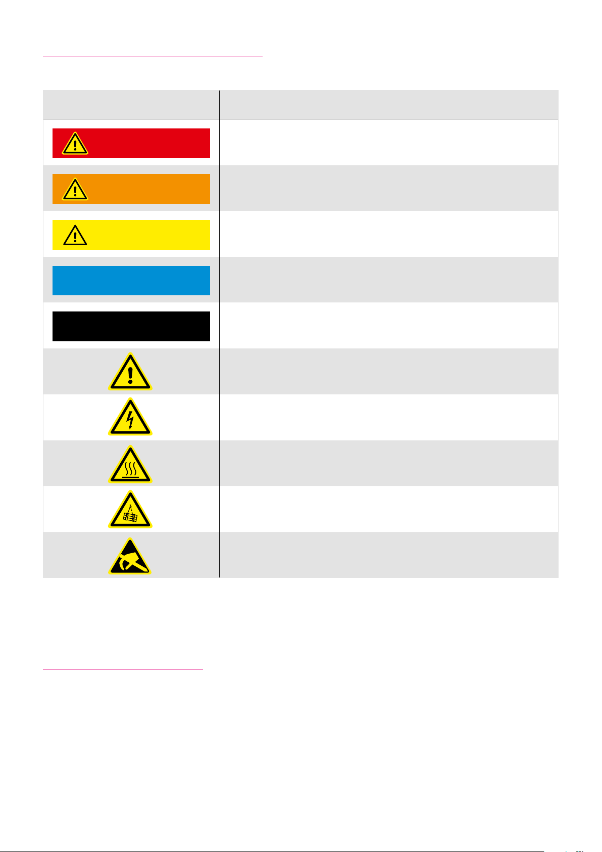
1.1 Description of Safety Alert Symbols
Symbol Meaning
Indicates an imminent hazardous situation. If this is not avoided, death or
DANGER
WARNING
ATTENTION
ADVICE
serious injury could occur.
Indicates a possible hazard. Care should be taken or death or serious injury
may result.
Indicates a possible hazard. Care should be taken or slight or minor injury
may result.
Describes a possibly harmful situation. Care should be taken to avoid damage
to the system and surroundings.
INFORMATION
This is not a safety symbol. This symbol indicates important information.
Warning of a general hazard. The type of hazard is determined by the
specific warning text.
Warning of dangerous electrical voltage and its eects.
Beware of hot surfaces.
Beware of suspended loads.
Precautions when handling electrostatic sensitive components.
1.2 Disclaimer and Copyright
The contents, images and graphics contained in this document are predected by copyright. In addition to the copyright, logos,
fonts, company and product names can also be predected by brand law or trademark law. The use of text, extracts or graphics
requires the permission of the publisher or rights holder.
We have checked the contents of this document. Since errors cannot be ruled out entirely, we do not accept liability for
mistakes which may have occurred. Notification of any mistake or suggestions for improvements will be gratefully received
and any necessary correction will be included in subsequent editions.
4 1019658 11/2014
Page 5
2. Safety and Installation Instructions
Please take note of the information and instructions in this document. Specialy designed models may dier in technical
detail. If in doubt, we strong recommend that you contact the manufacturer, giving the type designation and serial number
for clarification.
2.1 Hazards
DANGER
Electric products have dangerous live and redating parts. All work during connection, operation, repair and disposal must
be carried out by qualified personnel as described in the standards EN50110-1 and IEC 60364! Before starting any work, and
especially before opening covers, the actuator must be properly isolated. In addition to the main circuits, the user also has to
pay attention to any auxilliary circuits.
Observing the five safety rules:
• Disconnect mains
• Prevent reconnection
• Test for absence of harmful voltages
• Ground and short circuit
• Cover or close o nearby live parts
The measures taken above must only be withdrawn when the work has been completed and the device is fully assembled.
Improper handling can cause damage to persons and property. The respective national, local and factory specific regulations
must be adhered to.
DANGER
Electric, magnetic and electromagnetic fields are dangerous, in particular for persons with pacemakers, implants or similiar.
Vulnerable groups must not be in the immediate vicinity of the products themselves.
DANGER
Built-in holding brakes alone are not functional safe. Particularly with unsupported vertical axes, the functional safety and
security can only be achieved with additional, external mechanical brakes.
WARNING
The successful and safe operation of gears, products requires proper transport, storage and assembly as well as correct
operation and maintenance.
ATTENTION
The surface temperature of gears, motors and actuators can exceed 55 degrees Celsius. The hot surfaces should not be touched.
51019658 11/2014
Page 6

ADVICE
Movement and lifting of products with a mass > 20 Kg should only be carried out with suitable lifting gear.
ADVICE
Cables must not come into direct contact with hot surfaces.
INFORMATION
Special versions of drive systems and motors may have diering specifications. Please consider all data sheet, catalogues and
oers etc. sent concerning these special versions.
2.2 Intended Purpose
The Harmonic Drive® products are intended for industrial or commercial applications. They comply with the relevant parts of
the harmonised EN 60034 standards series.
Typical areas of application are robotics and handling, machine tools, packaging and food machines and similar machines.
The products may only be operated within the operating ranges and environmental conditions shown in the documentation
(altitude, degree of predection, temperature range etc).
Before plant and machinery which have Harmonic Drive® products built into them are commissioned, the compliance must be
established with the Machinery Directive, Low Voltage Directive and EMC guidelines.
Plant and machinery with inverter driven motors must satisfy the predection requirements in the EMC guidelines. It is the
responsibility of the installer to ensure that installation is undertaken correctly.
Signal and power lines must be shielded. The EMC instructions from the inverter manufacturer must be observed in order
that installation meets the EMC regulations.
2.3 Non Intended Purpose
The use of products outside the areas of application mentioned above or, inter alia, other than in the operating areas
or environmental conditions described in the documentation is considered as non-intended purpose.
ADVICE
The following areas of application are, inter alia, those considered as non-intended purpose:
• Aerospace
• Areas at risk of explosion
• Machines specially constructed or used for a nuclear purpose whose breakdown might lead to the emission of radio-activity
• Vacuum
• Machines for domestic use
• Medical equipment which comes into direct contact with the human body
• Machines or equipment for transporting or lifting people
• Special devices for use in annual markets or leisure parks
6 1019658 11/2014
Page 7

2.4 Declaration of Conformity
Harmonic Drive® gears are components for installation in machines as defined by the machine directive 89/392/EWG.
Commissioning is prohibited until such time as the end product has been proved to conform to the provisions of this directive.
Essential health and safety requirements were considered in the design and manufacture of these gear component sets.
This simplifies the implementation of the machinery directive by the end user for the machinery or the partly completed
machinery. Commissioning of the machine or partly completed machine is prohibited until the final product conforms to
the EC Machinery Directive.
71019658 11/2014
Page 8

3. Technical Description
3.1 Product Description
Compact with largest hollow shaft
HFUS-2A Series Component Sets are available in nine sizes with gear ratios of 30, 50, 80, 100, 120 and 160:1 oering
repeatable peak torques from 9 to 1840 Nm and a power density of up to 384 Nm/kg.
If required, the Component Sets are available as specific configurations tailored to your application, including special
lubricants for extended temperature ranges or special materials for extreme ambient conditions. Consisting of just
three individual components, they are very lightweight and compact.
The enlarged hollow shaft can be used to feed through supply lines, shafts or cables for further axes. Due to their
positioning accuracy stable machine properties with short cycle times are guaranteed.
-
8 1019658 11/2014
Page 9
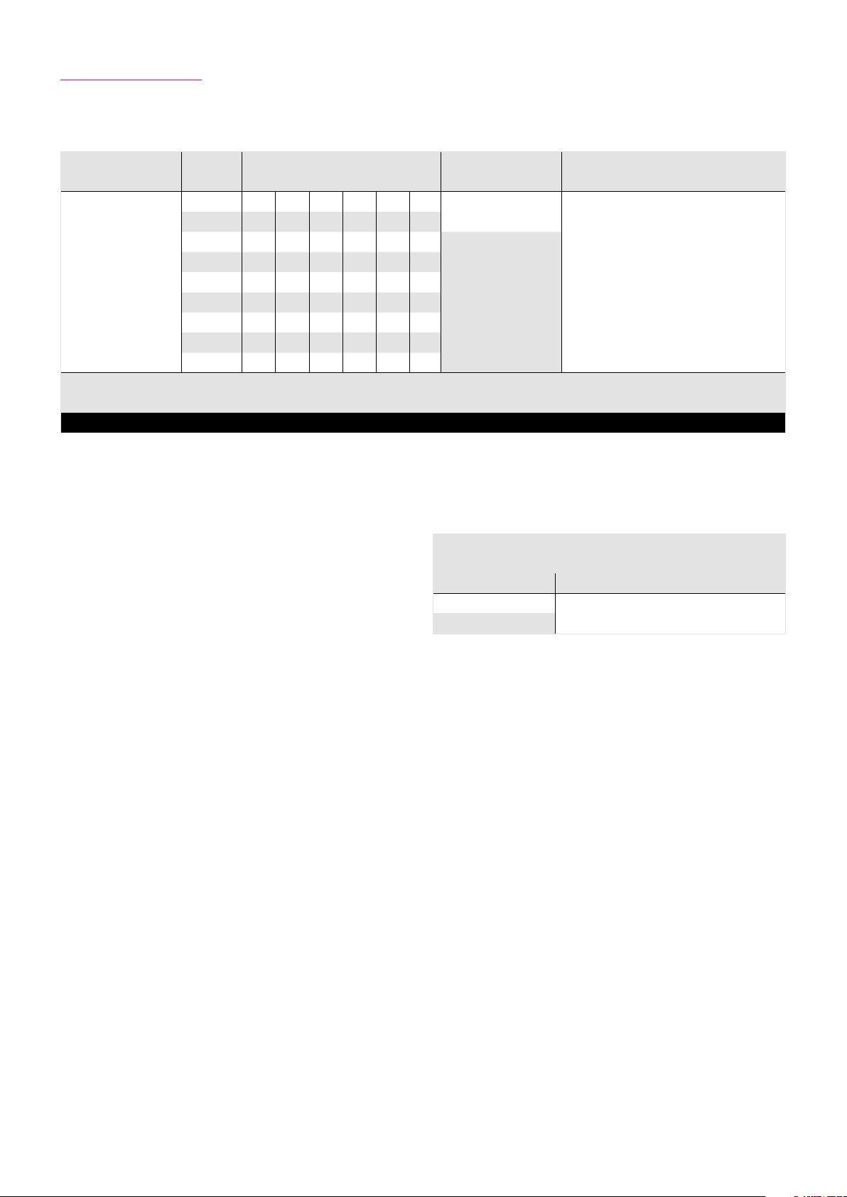
3.2 Ordering Code
Table 9.1
Series Size Ratio
14 30 50 80 100
17 30 50 80 100 120
1)
Version Special design
2A-R
20 30 50 80 100 120 160
25 30 50 80 100 120 160
HFUS
32 30 50 80 100 120 160
40 50 80 100 120 160
2A-GR
According to customer requirements
45 50 80 100 120 160
50 50 80 100 120 160
58 50 80 100 120 160
Ordering code
HFUS 25 100 2A-GR SP
1)
The ratios shown here are for a standard driving configuration with the circular spline fixed, the Wave Generator used for the input and the Flexspline attached to the
output. Other configurations are possible. Please consult chapter 4 “Ratio”.
Table 9.2
Version
Ordering code Description
2A-R
2A-GR
Component Set
Erläuterungen zu den technischen Daten finden Sie im Kapitel „Glossar“
91019658 11/2014
Page 10

3.3 Technical Data
3.3.1 General Technical Data
Table 10.1
Unit HFUS-14-2A HFUS-17-2A
Ratio i [ ] 30 50 80 100 30 50 80 100 120
Repeatable peak torque T
Average torque T
Rated torque T
Momentary peak torque T
Maximum input speed (Oil Lubrication) n
Maximum input speed (Grease Lubrication) n
Average input speed (Oil Lubrication) n
Average input speed (Grease Lubrication) n
Moment of inertia J
Weight m [kg] 0.11 0.18
[Nm] 9.0 18 23 28 16 34 43 54 54
R
[Nm] 6.8 6.9 11 11 12 26 27 39 39
A
[Nm] 4.0 5.4 7. 8 7. 8 8.8 16 22 24 24
N
[Nm] 17 35 47 54 30 70 87 110 86
M
[rpm] 14000 10000
in (max)
[rpm] 8500 7300
in (max)
[rpm] 6500 6500
av (max)
[rpm] 3500 3500
av (max)
[x10-4 kgm²] 0.033 0.079
in
Table 10.2
Unit HFUS-20-2A HFUS-25-2A
Ratio i [ ] 30 50 80 100 120 160 30 50 80 100 120 160
Repeatable peak torque T
Average torque T
Rated torque T
Momentary peak torque T
Maximum input speed (Oil Lubrication) n
Maximum input speed (Grease Lubrication) n
Average input speed (Oil Lubrication) n
Average input speed (Grease Lubrication) n
Moment of inertia J
[Nm] 27 56 74 82 87 92 50 98 137 157 167 176
R
[Nm] 20 34 47 49 49 49 38 55 87 108 108 108
A
[Nm] 15 25 34 40 40 40 27 39 63 67 67 67
N
[Nm] 50 98 127 147 147 147 95 186 255 284 304 314
M
[rpm] 10000 7500
in (max)
[rpm] 6500 5600
in (max)
[rpm] 6500 5600
av (max)
[rpm] 3500 3500
av (max)
[x10-4 kgm²] 0.193 0.413
in
Weight m [kg] 0.31 0.48
10 1019658 11/2014
Page 11
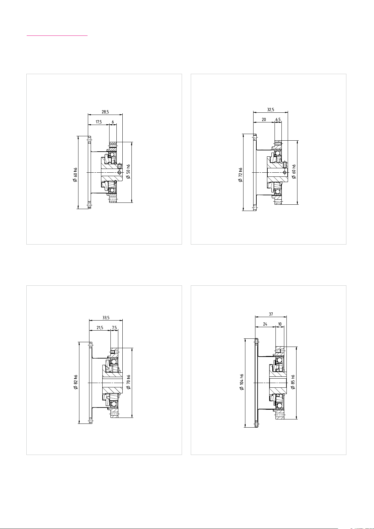
3.3.2 Dimensions
Illustration 11.1 Illustration 11.2[mm]
HFUS-14-2A HFUS-17-2A
[mm]
Illustration 11.3 Illustration 11.4[mm] [mm]
HFUS-20-2A HFUS-25-2A
QUICKLINK
www.harmonicdrive.de/CAD3050
111019658 11/2014
Page 12

Table 12.1
Unit HFUS-32-2A HFUS-40-2A
Ratio i [ ] 30 50 80 100 120 160 50 80 100 120 160
Repeatable peak torque T
Average torque T
Rated torque T
Momentary peak torque T
Maximum input speed (Oil Lubrication) n
Maximum input speed (Grease Lubrication) n
Average input speed (Oil Lubrication) n
Average input speed (Grease Lubrication) n
Moment of inertia J
[Nm] 100 216 304 333 353 372 402 519 568 617 647
R
[Nm] 75 108 167 216 216 216 196 284 372 451 451
A
[Nm] 54 76 118 137 137 137 137 206 265 294 294
N
[Nm] 200 382 568 647 686 686 686 980 1080 1180 1180
M
[rpm] 7000 5600
in (max)
[rpm] 4800 4000
in (max)
[rpm] 4600 3600
av (max)
[rpm] 3500 3000
av (max)
[x10-4 kgm²] 1.69 4.5
in
Weight m [kg] 0.97 1.86
Table 12.2
Unit HFUS-45-2A HFUS-50-2A
Ratio i [ ] 50 80 100 120 160 50
Repeatable peak torque T
Average torque T
Rated torque T
Momentary peak torque T
Maximum input speed (Oil Lubrication) n
Maximum input speed (Grease Lubrication) n
Average input speed (Oil Lubrication) n
Average input speed (Grease Lubrication) n
Moment of inertia J
[Nm] 500 706 755 823 882 715 941 980 1080 1180
R
[Nm] 265 390 500 620 630 350 519 666 813 843
A
[Nm] 176 313 353 402 402 245 372 470 529 529
N
[Nm] 950 1270 1570 1760 1910 1430 1860 2060 2060 2450
M
[rpm] 5000 4500
in (max)
[rpm] 3800 3500
in (max)
[rpm] 3300 3000
av (max)
[rpm] 3000 2500
av (max)
[x10-4 kgm²] 8.68 12.5
in
1)
80 100 120 160
Weight m [kg] 2.64 3.53
1)
Only with oil lubrication. Grease lubrication is possible if the average torque Tav does not exceed half the rated torque TN.
12 1019658 11/2014
Page 13
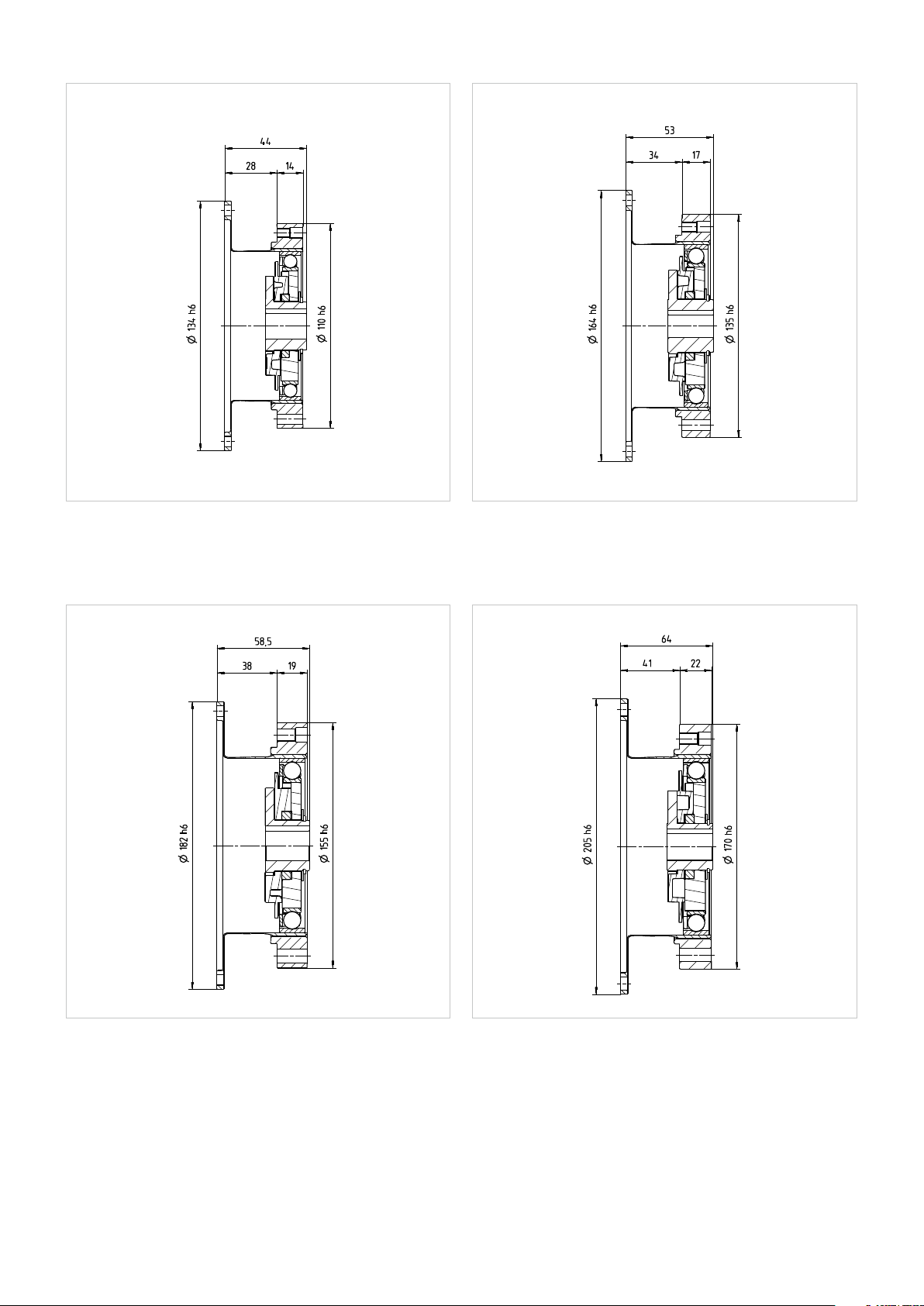
Illustration 13.1 Illustration 13.2[mm] [mm]
HFUS-32-2A HFUS-40-2A
Illustration 13.3 Illustration 13.4[mm] [mm]
HFUS-45-2A HFUS-50-2A
QUICKLINK
www.harmonicdrive.de/CAD3050
131019658 11/2014
Page 14
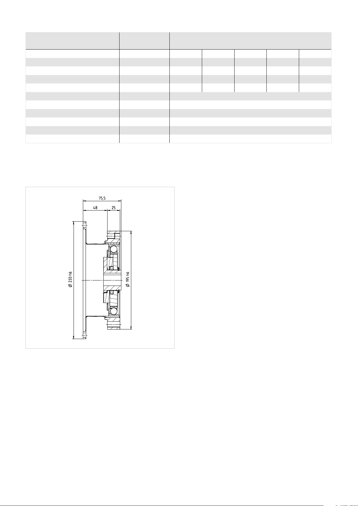
Table 14.1
Unit HFUS-58-2A
Ratio
Repeatable peak torque
Average torque
Rated torque
Momentary peak torque
Maximum input speed (Oil Lubrication)
Maximum input speed (Grease Lubrication)
Average input speed (Oil Lubrication)
Average input speed (Grease Lubrication)
Moment of inertia
Weight
1)
Only with oil lubrication. Grease lubrication is possible if the average torque Tav does not exceed half the rated torque TN.
Illustration 14.2
HFUS-58-2A
i [ ]
[Nm]
T
R
[Nm]
T
A
[Nm]
T
N
[Nm]
T
M
[rpm]
n
in (max)
[rpm]
n
in (max)
[rpm]
n
av (max)
[rpm]
n
av (max)
[x10-4 kgm²]
J
in
m [kg]
[mm]
1)
50
1020 1480 1590 1720 1840
520 770 1060 1190 1210
353 549 696 745 745
1960 2450 3180 3330 3430
80 100 120 160
4000
3000
2700
2200
27.3
5.17
QUICKLINK
www.harmonicdrive.de/CAD3050
14 1019658 11/2014
Page 15
3.3.3 Minimum Housing Clearance
Table 15.1
Size 14 17 20 25 32 40 45 50 58
u 1.7 2.1 2.0 2.0 2.0 2.0 2.3 2.5 2.9
ØW 31 38 45 56 73 90 101 113 131
x 24.5 27.5 30.5 35.5 43.5 53.0 59.0 65.0 75.5
y 2.9 3.6 3.7 4.2 4.8 5.4 6.1 6.8 7.9
ØZ 38 45 53 66 86 106 119 133 154
Illustration 15.2
[mm]
3.3.4 Accuracy
Table 15.3 [arcmin]
Size 14 17 ≥20
Ratio 30 ≥50 30 ≥50 30 ≥50
Transmission accuracy
1)
<2 <1.5 <1.5 <1.5 <1.5 <1
Hysteresis loss <3 <1 <3 <1 <3 <1
Lost Motion <1
Repeatability < ± 0.1
1)
Higher precision on request
3.3.5 Torsional Stiness
Table 15.4
Size 14 17 20 25 32 40 45 50 58
T
[Nm] 2 3.9 7 14 29 54 76 108 168
1
[Nm]
T
2
i = 30
i = 50
i > 50
K
[x10³ Nm/rad]
3
K
[x10³ Nm/rad]
2
K
[x10³ Nm/rad]
1
K
[x10³ Nm/rad]
3
K
[x10³ Nm/rad]
2
K
[x10³ Nm/rad]
1
K
[x10³ Nm/rad]
3
K
[x10³ Nm/rad]
2
K
[x10³ Nm/rad]
1
6.9 12 25 48 108 196 275 382 598
3.4 6.7 11 21 49 – – – –
2.4 4.4 7.1 13 30 – – – –
1.9 3.4 5.7 10 24 – – – –
5.7 13 23 44 98 180 260 340 540
4.7 11 18 34 78 140 200 280 440
3.4 8.1 13 25 54 100 150 200 310
7.1 16 29 57 12 230 330 440 710
6.1 14 25 50 11 200 290 400 61 0
4.7 10 16 31 67 130 180 250 400
151019658 11/2014
Page 16
4. Driving Arrangements
A variety of dierent driving arrangements are possible with Harmonic Drive® gears.
Equation 16.1
Ratio i =
Input speed
Output speed
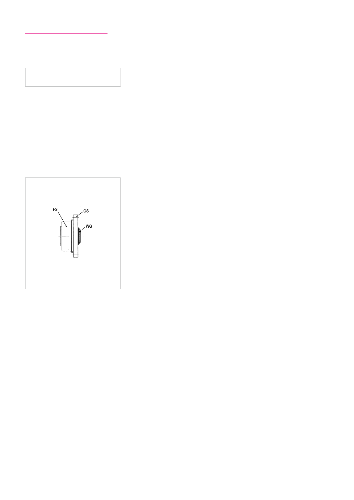
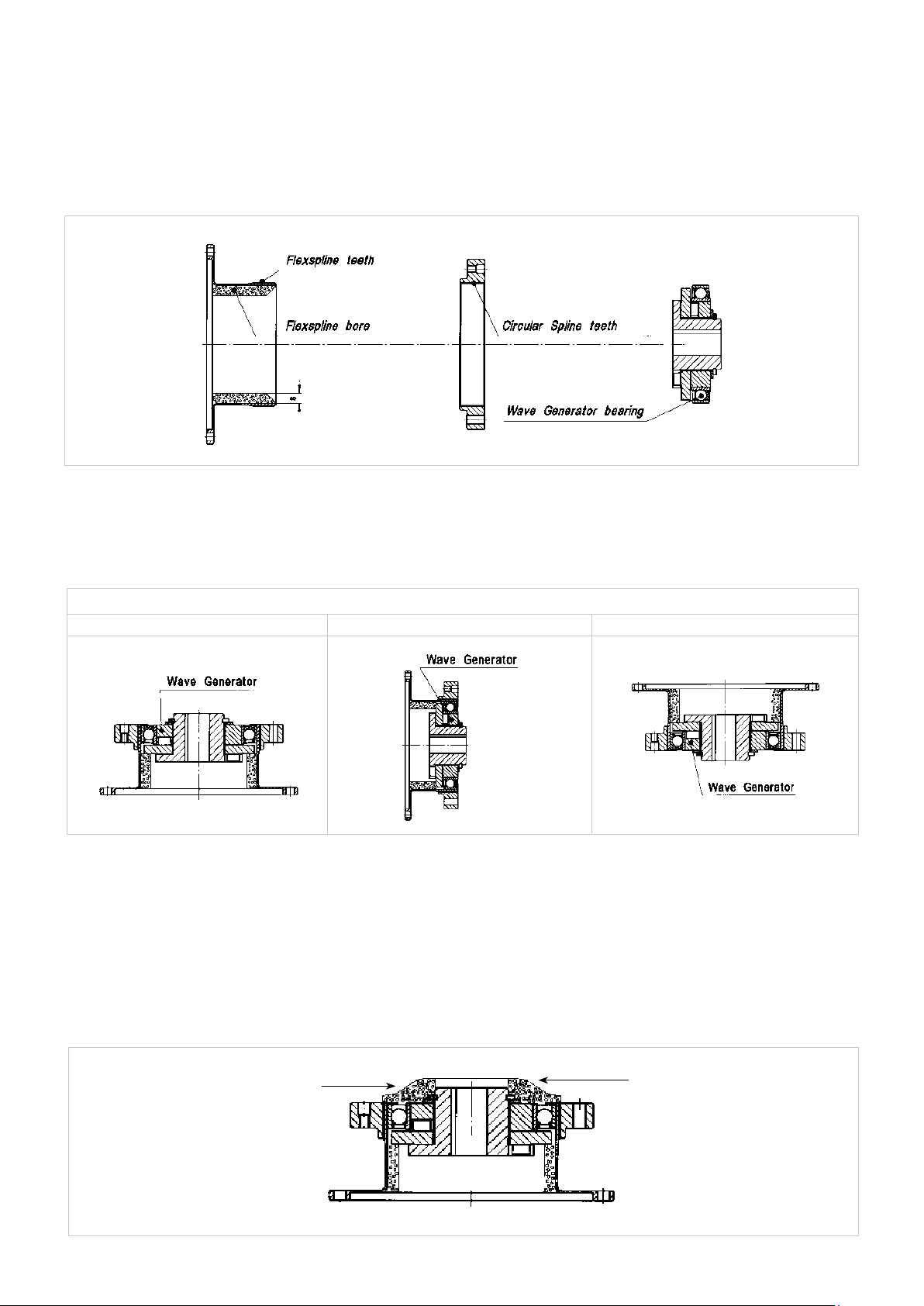
Overview Harmonic Drive® Products
The three main components of the Harmonic Drive® units, Circular Spline (CS), Flexspline (FS) and Wave Generator (WG) can
be seen in the illustration 16.2.
Illustration 16.2
The values for ratios of Harmonic Drive® gears refer to the standard input and output arrangement (example 1 in the table
below). Other arrangements are possible, and also shown in the table.
16 1019658 11/2014
Page 17
Ratio
1) 2) 3)
WG
FS
CS
Reduction gearing
CS Fixed
WG Input
FS Output
Equation 17.1
Ratio = -
Input and output rotate in opposite directions. Input and output rotate in same direction. Input and output rotate in same direction.
i
1
Reduction gearing
FS Fixed
WG Input
CS Output
Equation 17.2
Ratio =
i +1
1
Reduction gearing
WG Fixed
FS Input
CS Output
Equation 17.3
Ratio =
i +1
1
4) 5) 6)
Speed increaser gearing
WG Fixed
CS Input
FS Output
Equation 17.4
Speed increaser gearing
CS Fixed
FS Input
WG Output
Equation 17.5
Speed increaser gearing
FS Fixed
CS Input
WG Output
Equation 17.6
Ratio =
Input and output rotate in same direction. Input and output rotate in opposite directions. Input and output rotate in same direction.
i +1
Ratio =
i
1
i
Ratio =
1
i +1
7)
Dierential gear
WG Control input
CS Main drive input
FS Main drive output
Numerous dierential functions can be obtained by combinations of the speed and rotational direction of the three basic elements.
Please refer to our broshure “Dierential Applications” available to download from our website.
171019658 11/2014
Page 18
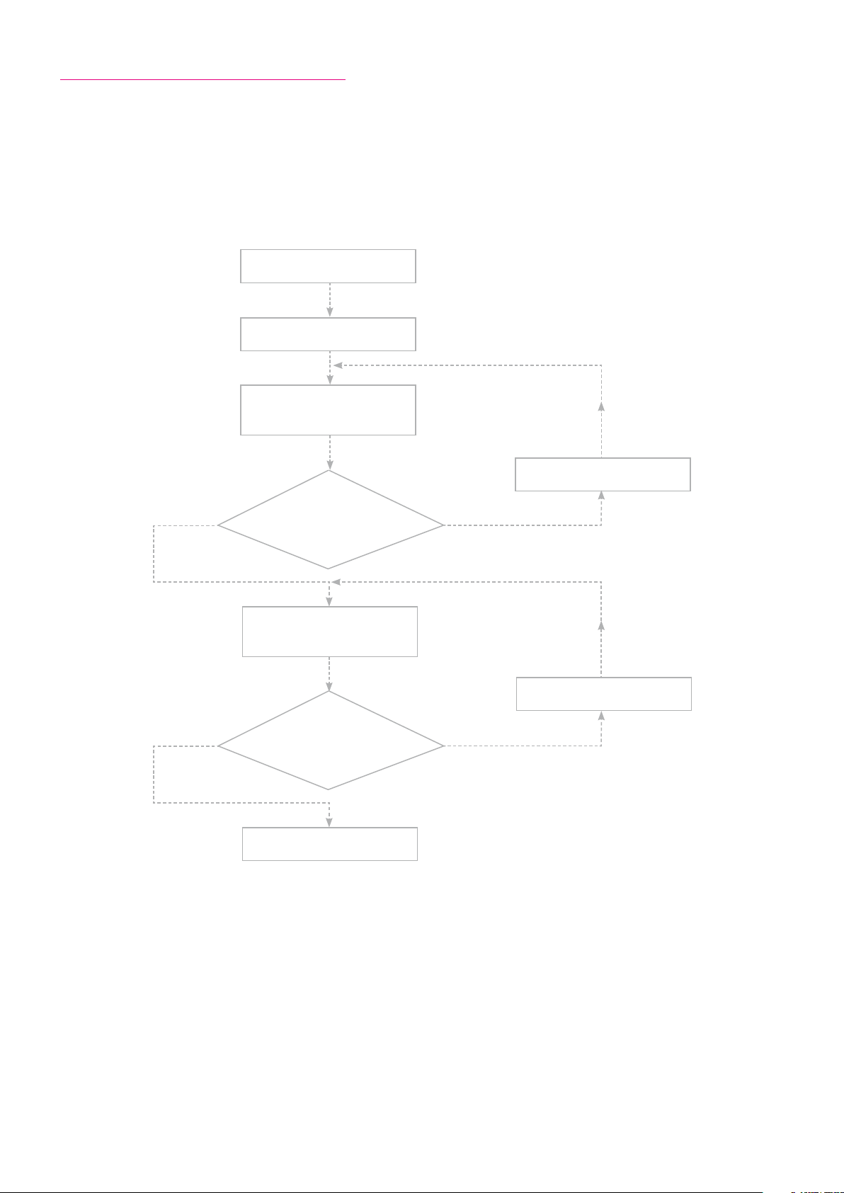
4.1 Selecting Harmonic Drive® Gears
When choosing a gear, both torque as well as stiness requirements should be take into account. In robot applications, for
example, the necessary torque is the more crucial factor for the gear size, while the torsional stiness is often decisive in
machine tool applications. We therefore recommend that you always take both criteria into account according to the following
procedures.
Application
Gear preselection
Torque based dimensioning
according to selection
procedure on page 19
Selection of a
bigger size
Yes
Yes
Gear size
sucient?
Stiness based dimensioning
according to selection
procedure on page 22
Gear size
sucient?
End of gear
selection
No
Selection of a
bigger size
No
18 1019658 11/2014
Page 19

4.1.1 Torque Based Dimensioning
Output Data
Torques T1...T
during the load phases t
during the pause time t
and output speeds n
Emergency stop/momentary peak torque T
at output speed n
and duration t
Equation 19.2
Tav =
Illustration 19.1
[Nm]
n
...tn [s]
1
p
...n
1
n
[Nm]
k
k
k
[s]
[rpm]
[rpm]
[s]
Torque Speed
n
1
t
1
T
1
Load limit 1,
Calculation of the average output torque T
3
|n1 · T
3
| · t
1
|n1| · t1 +|n2| · t
3
+|n
· T
| · t
2
+ ... + |nn · T
2
+ ... + |nn| · t
2
1
2
3
n
n
| · t
n
2
n
3
t
2
T
2
t
3
T
3
n
1
n
p
t
p
Time
t
1
T
1
Time
av
n
Equation 19.3
Equation 19.4
Equation 19.6
Equation 19.8
Calculation of the average output speed
n
= n
in max
out max
Load limit 2, T
T
≤ T
max
R
Values for T
|n1|· t1 + |n2| · t
=
n
out av
see rating tables
A
Selection of a bigger size
Tav ≤ T
A
+ ... + |nn| · t
t1 + t
+ ... + t
2
2
n
n
+ t
p
Permissible maximum input speed
· i ≤ Maximum input speed (see rating table)
Equation 19.9 Equation 19.10
R
Load limit 3, T
Tk ≤ T
No
Equation 19.5
Average input speed
n
= i · n
in av
out av
Equation 19.7
Permissible average input speed
n
≤ Limit for average input speed
in av
(see rating table)
Allowable number of momentary peak torques
M
M
N
k max
10
=
2·
4
n
k
60
·i·t
4
< 10
k
Equation 19.11
Values for Ln see table 21.1
L
Operating life
Rated input speed · ( Rated torque TN
*
·
= L
50
n
n
in av
3
)
T
av
191019658 11/2014
Page 20

Output Data
T1 = 400 Nm t1= 0.3 s n1 = 7 rpm
= 320 Nm t2= 3.0 s n2 = 14 rpm
T
2
= 200 Nm t3= 0.4 s n3 = 7 rpm
T
3
= 500 Nm tk= 0.15 s nk= 14 rpm
T
k
t
= 0.2 s np= 0 rpm
p
Ratio i = 120
= 30000 h (required)
Life L
50
calculation of the average output torque T
Load limit 1,
3
7 rpm · (400 Nm)
=
T
av
3
· 0.3 s + 14 rpm · (320 Nm)3 · 3 s + 7 rpm · (200 Nm)
7 rpm · 0.3 s + 14 rpm · 3 s + 7 rpm · 0.4 s
Tav = 319 Nm ≤ TA = 451 Nm
Calculation of the average
output speed
7 rpm · 0.3 s + 14 rpm · 3 s + 7 rpm · 0.4 s
n
out av
=
0.3 s + 3 s + 0.4 s + 0.2 s
=12.0 rpm
Permissible maximum input speed
= 14 rpm · 120 = 1680 rpm ≤ 4000 rpm
n
in max
Load limit 2, T
= 400 Nm ≤ TR = 617 Nm Tk = 500 Nm ≤ TM = 1180 Nm
T
max
R
Load limit 3, T
av
3
· 0.4 s
Selected size
HFUC-40-120-2A-GR
Average input speed
= 120 · 12.0 rpm = 1440 rpm
n
in av
Permissible average input speed
n
= 1440 rpm ≤ 3000 rpm
in av
M
Allowable number of
momentary peak torques
4
=
14 · 120
2 ·
60
10
N
k max
· 0.15
= 1190 < 10
4
Operating life
HFUC-40-120-2A-GR:
35000 h · 2000 rpm ·
L
=
50
294 Nm
1440 rpm 319 Nm
(
3
)
= 38054 h > 30000 h
L
50
20 1019658 11/2014
Page 21

4.1.2 Life of the Wave Generator Bearing
Given that the Harmonic Drive® Gear is rated to provide infinite fatigue life for the Flexspline, the life expectancy is based on
the average life of the Wave Generator bearing. The rated torque at the rated speed given in the rating table is based on the
mean L50 bearing life.
The life expectancy of a component set or an unit operating at an input speed n (rpm) and output torque T (Nm) may be
estimated from equation 21.2.
Table 21.1
Harmonic Drive® series L
CobaltLine, CSG, SHG 50000
HFUC, HFUS, CSD, CPU, CSF, SHD 35000
PMG gearbox 15000
Equation 21.2
n
T
N
3
nin
av
( )
T
N
av
L50 = L
n
Equation 21.3
1
L
≈
–
•L
50
10
5
nN = Rated input speed [rpm]
n
= Average input speed [rpm] (equation 19.5)
in av
TN = Rated output torque at rated speed [Nm]
Tav = Average output torque [Nm] (equation 19.2)
Ln = See table 21.1
[h]
n
211019658 11/2014
Page 22

4.1.3 Stiness Based Dimensioning
In addition to the “Torque Based Dimensioning” stated on page 19, we recommend that you carry out a selection based on
stiness. For this, the values provided in table 22.1 for the individual resonance frequencies recommended for each application
should be taken into account.
Table 22.1
Application f
Slowly rotating turntables, base axes of slow moving welding robots (not laser welding), slowly rotating welding and swinging
tables, gantry robot axes
Base axes of revolute robots, hand axes of revolute robots with low requirements regarding dynamic perfomance, tool
revolvers, tool magazines, swivelling and positioning axes in medical and measuring devices
Standard applications in general mechanical engineering, tilting axes, palette changers, highly dynamic tool changers, revolvers
and magazines, hand axes of robots, scara robots, gantry robots, polishing robots, dynamic welding manipuators, base axes of
welding robots (laser welding), swivelling and positioning axes of medical equipment
B/C axes in 5 axis grinding machines, hand axes of welding robots (laser welding), milling heads for plastics machining ≥ 20
C axes in turning machines, milling heads for light metal machining, milling heads for woodworking (chipboards etc.) ≥ 25
Milling heads for woodworking (hardwood etc.) ≥ 30
C axes in turning machines* ≥ 35
[Hz]
n
≥ 4
≥ 8
≥ 15
Milling heads for metal machining*, B axes in turning milling centers for metal machining ≥ 40
Milling heads for metal machining*, B axes in turning milling centers for metal machining with high requirements regarding
surface quality*
Milling heads for metal machining with very high requirements regarding surface quality* ≥ 60
* Depending on the application, a secondary gear stage may be useful. Please contact Harmonic Drive AG for more information.
≥ 50
22 1019658 11/2014
Page 23

Selection Example: Stiffness Based Dimensioning
Resonance Frequency (Gear Output)
The formula
Equation 23.1
1
K
fn = [Hz]
2�
fn = Resonance frequency [Hz]
K1 = Gear torsional stiness K1 [Nm/rad]
J = Load moment of inertia [kgm2]
1
J
allows the calculation of the resonance frequency at the gear output from the given torsional stiness, K1, of the Harmonic Drive®
gear and the load‘s moment of inertia. The calculated frequency should correspond with the value provided in table 22.1. The
higher the load‘s moment of inertia, the more influence the application has on the gear selection. If the moment of inertia = 0,
the selected application has no numerical influence on the selection result.
Resonance Speed (Gear Input)
The resonance speed nn on the input side (motor side) can be calculated using the formula
nn = fn*30 [rpm]
During operation, we recommend that you pass the resonance speed rapidly. This can be achieved by selecting a suitable gear
ratio. Another possibility is to select suitable gear stiness such that the resonance speed lies
beyond the required speed range.
Selection Example
HFUC-40-120-2A-GR preselected from “Selection Procedure” on page 20.
Intended application: milling head for woodworking
Moment of inertia at the gear output: 7 kgm2. Recommended resonance frequency from table 22.1: ≥ 30 Hz.
Resonance frequency using the preselected gear
HFUC-40-120-2A-GR:
1.3 . 10
7
5
1
= . = 22 [Hz]
f
n
2�
According to stiness based dimensioning, this gear size is too small for the application.
The larger gear HFUC-50-120-2A-GR results in a resonance frequency of:
2.5 . 10
7
5
fn = . = 30 [Hz]
1
2�
Based on stiness based dimensioning, the gear HFUC-50-120-2A-GR is recommended.
The resonance speed at the input (motor) amounts to:
nn = 30*30 = 900 [rpm]
Either, this speed should be passed without stopping when accelerating / braking, or it should
lie beyond the utilised speed range.
231019658 11/2014
Page 24

4.2 Calculation of the Torsion Angle
Calculation of the Torsion Angle φ at Torque T:
Equation 24.1 Equation 24.2 Equation 24.3
<
T T1
–
T
φ =
K1
φ = Angle [rad]
T = Torque [Nm]
K = Stiness [Nm/rad]
Example: HFUC-32-100-2UH
T = 60 Nm K1 = 6.7 . 104 Nm/rad
T1 = 29 Nm K2 = 1.1 . 105 Nm/rad
T2 = 108 Nm K3 = 1.2 . 105 Nm/rad
4.3 Accuracy of the Oldham Coupling
φ =
T
<
1
T≤T
2
T
T - T
1
+
K
K
1
Equation 24.4
<
T T
2
T
- T
1
2
29 Nm
φ =
.
6.7
104 Nm/rad
φ = 7.15 . 10
-4
rad
T
1
φ =
K
1
60 Nm - 29 Nm
+
.
104 Nm/rad
11
2
+ +
K
2
1
T - T
K
2
3
φ = 2.5 arc min
180 . 60
φ [arc min] = φ [rad]
.
�
Information concerning the Oldham coupling can be found in section 5.5.
In the region of tooth engagement Harmonic Drive® gears have no backlash. If an Oldham coupling is used for the compensation of eccentricity errors of the motor shaft, a small backlash in the range of a few seconds of arc can occur at the output
shaft, as listed in table 24.5.
Table 24.5
Sizes 14 17 20 25 32 40 45 50 58
30 60 33 28 28 23 – – – –
50 36 20 17 17 14 14 12 12 10
Ratio
80 23 13 11 11 9 9 8 8 6
100 18 10 9 9 7 7 6 6 5
120 – 8 8 8 6 6 5 5 4
160 – – 6 6 5 5 4 4 3
[arcsec]
24 1019658 11/2014
Page 25

4.4 Eciency Versus Load
Eciency for Harmonic Drive® Gears varies depending on the output torque. The eciency curves are for gears operating at
rated output torque. Eciency for a gear operating at a load below the rated torque may be estimated using a compensation
curve and equation as shown on the next page.
4.4.1 Eciency Calculations
Table 25.1
Calculation Procedure Example
Efficiency of HFUC-20-80-2A-GR with
input speed n=1000 rpm
output torque T=19.6 Nm at 20° C ambient temperature.
Lubrication: Oil
The efficiency may be determined
using the efficiency graphs.
Calculate
the torque factor V.
T
av
V =
T
N
With:
= Average torque
T
av
TN = Rated torque at rated speed
K depending on gear type and V,
see illustration 25.4
Efficiency
η
= η . K
L
[Equation 25.2]
[Equation 25.3]
From matching chart
η = 78 %
Tav = 19.6 Nm
TN = 34.0 Nm
19.6 Nm
V =
34.0 Nm
1.0
K
0.8
0.6
0.4
0.2
= 78 . 0.93 = 73 %
η
L
0
= 0.57
0.2 0.4
0.6 0.8
1.0
V
Calculating Factor K
Illustration 25.4
K
251019658 11/2014
Page 26

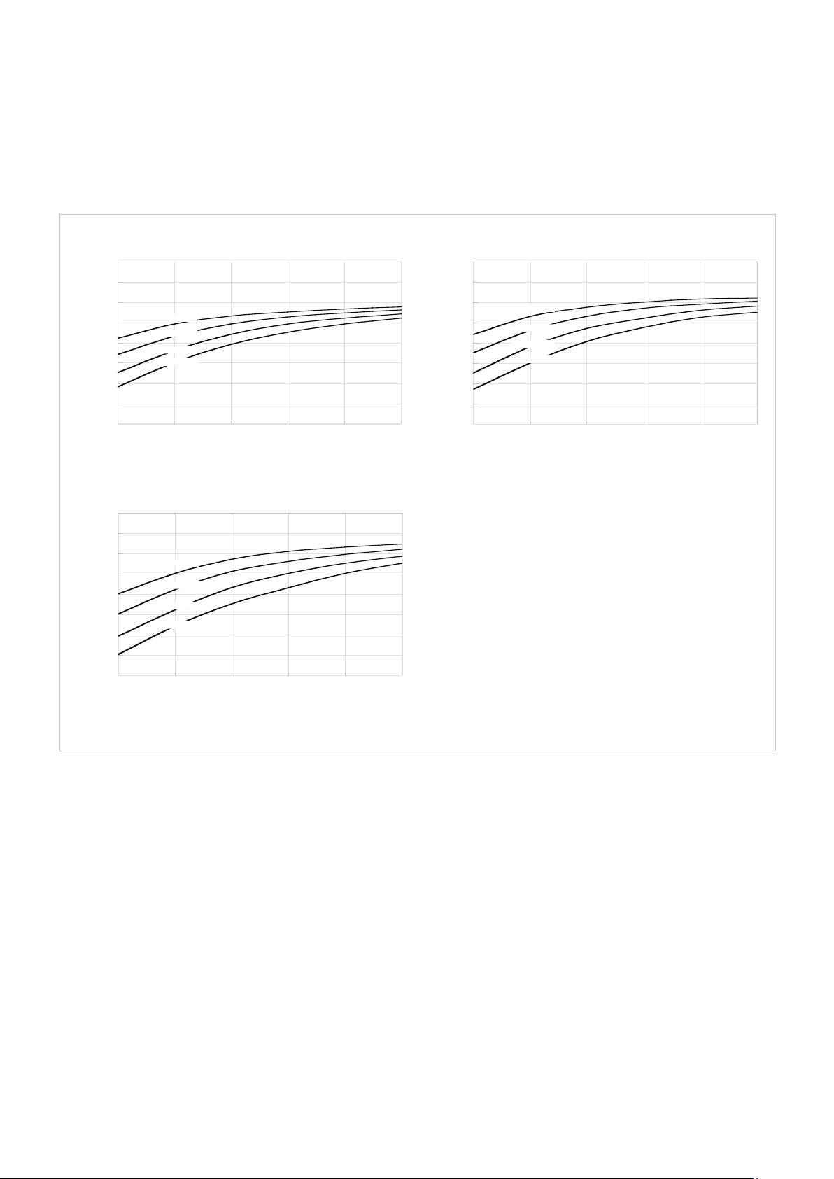
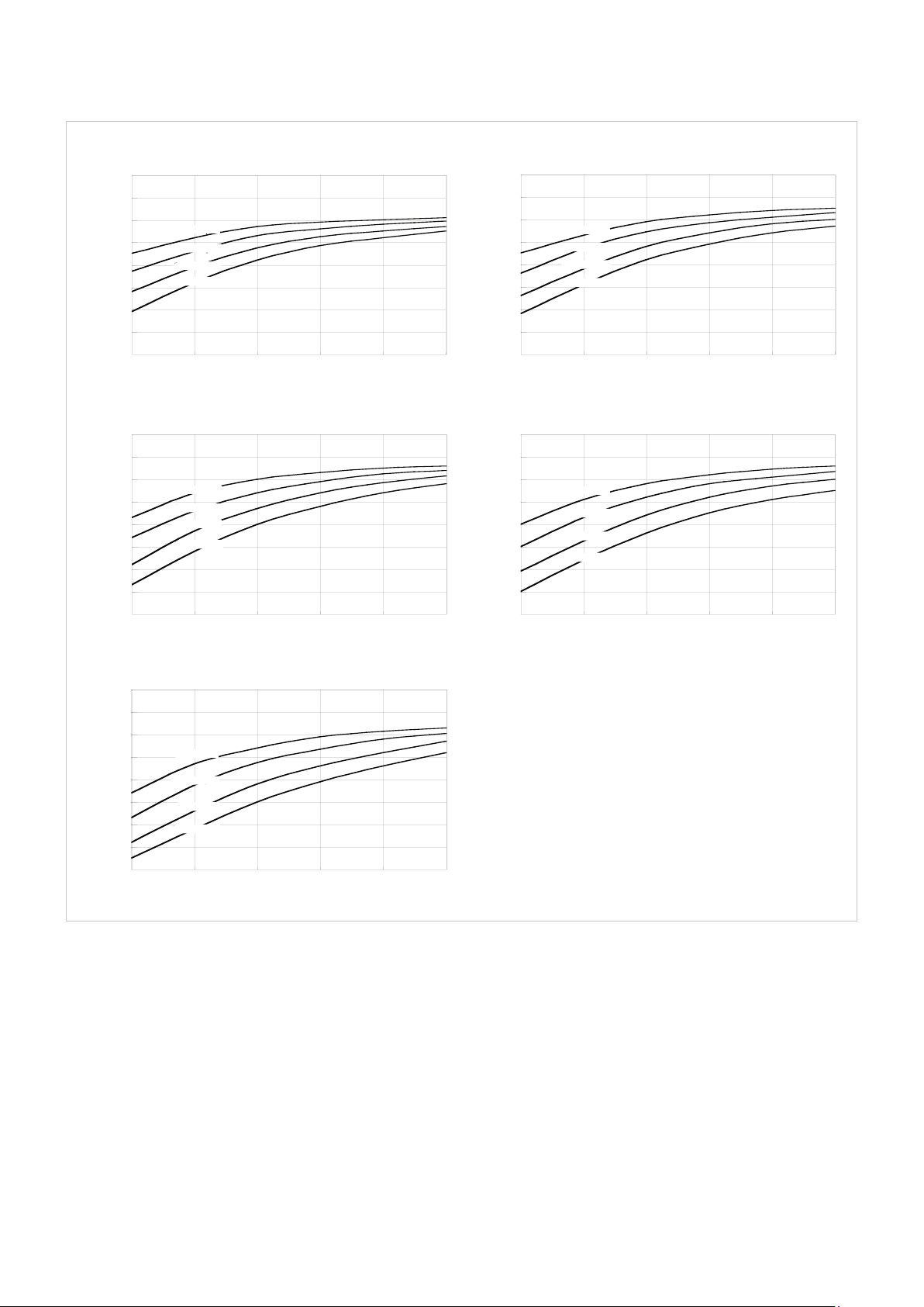
4.4.2 Eciency Tables
Tables Oil
Eciency for oil lubrication at rated torque.
Illustration 26.1
Ratio = 30, 50, 80
100
90
80
70
60
50
Efficiency [%]
40
30
20
0 10 20 30 40
500 rpm
1000 rpm
2000 rpm
3500 rpm
Temperature [°C]
Ratio = 120
100
90
80
70
60
50
Efficiency [%]
40
30
20
0 10 20 30 40
500 rpm
1000 rpm
2000 rpm
3500 rpm
Temperature [°C]
Ratio = 100
100
90
80
70
60
50
40
30
20
0 10 20 30 40
500 rpm
1000 rpm
2000 rpm
3500 rpm
Temperature [°C]
Ratio = 160
100
90
80
70
60
50
Efficiency [%] Efficiency [%]
40
30
20
0 10 20 30 40
500 rpm
1000 rpm
2000 rpm
3500 rpm
Temperature [°C]
26 1019658 11/2014
Page 27
Tables Grease
Eciency for grease lubrication at rated torque
Harmonic Drive® Grease.
Size 14
Illustration 27.1
Ratio = 30
100
90
80
70
60
50
Efficiency [%]
40
30
20
-10 0 10 20 30 40
500 rpm
1000 rpm
2000 rpm
3500 rpm
Temperature [°C]
Ratio = 100
100
90
80
70
60
50
Efficiency %]
40
30
20
-10 0 10 20 30 40
500 rpm
1000 rpm
2000 rpm
3500 rpm
Temperature [°C]
Ratio = 50, 80
100
90
80
70
60
50
Efficiency [%]
40
30
20
-10 0 10 20 30 40
500 rpm
1000 rpm
2000 rpm
3500 rpm
Temperature [°C]
271019658 11/2014
Page 28
Size 17 - 58
Illustration 28.1
Ratio = 30
100
90
80
70
60
50
Efficiency [%]Efficiency [%]
40
30
20
-10 0 10 20 30 40
500 rpm
1000 rpm
2000 rpm
3500 rpm
Temperature [°C]
Ratio = 50
100
90
80
70
60
50
Efficiency [%]
40
30
20
-10 0 10 20 30 40
500 rpm
1000 rpm
2000 rpm
3500 rpm
Temperature [°C]
Ratio = 80, 100 Ratio = 120
100
90
80
70
60
50
40
30
20
-10 0 10 20 30 40 -10 0 10 20 30 40
500 rpm
1000 rpm
2000 rpm
3500 rpm
100
90
80
70
60
50
Efficiency [%]
40
30
20
500 rpm
1000 rpm
2000 rpm
3500 rpm
Temperature [°C] Temperature [°C]
Ratio = 160
100
90
80
70
60
50
Efficiency [%]
40
30
20
-10 0 10 20 30 40
500 rpm
1000 rpm
2000 rpm
3500 rpm
Temperature [°C]
28 1019658 11/2014
Page 29
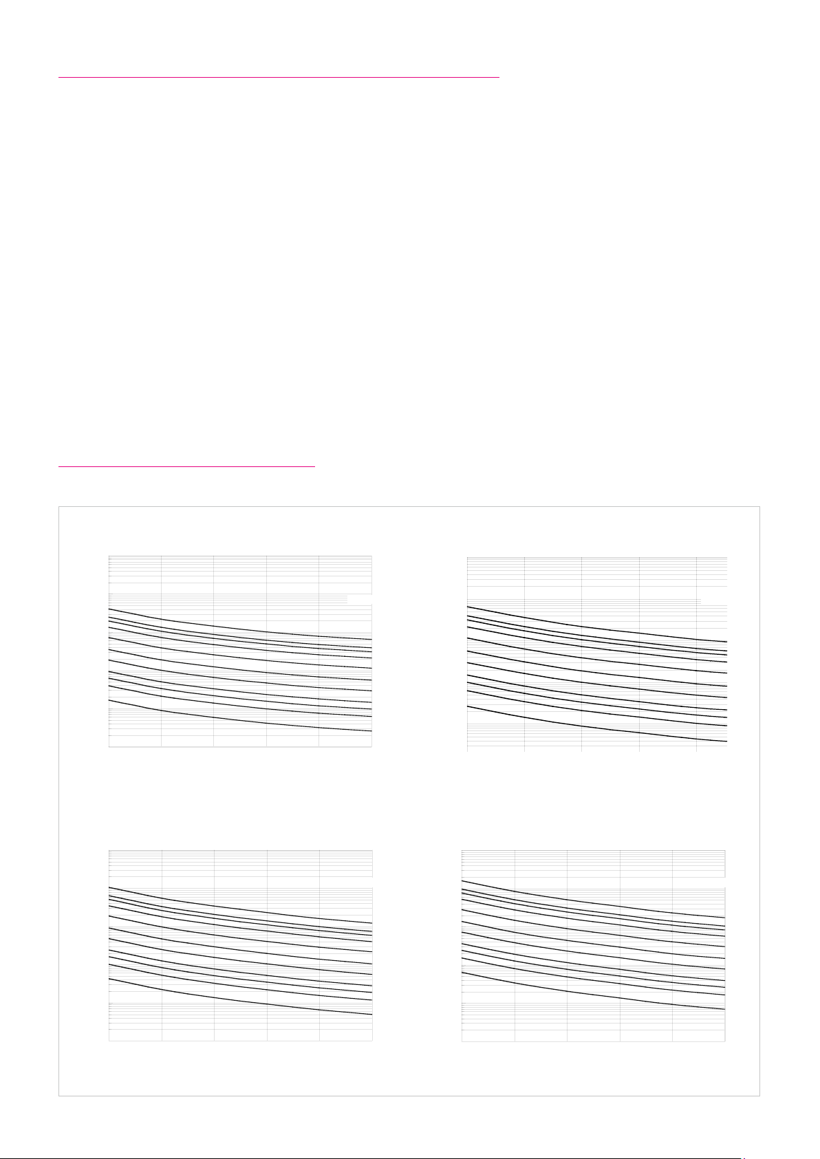
4.5 No Load Starting-, Back Driving- and Running Torque
No Load Running Torque
The no load running torque is the torque required to maintain rotation of the input element (high speed side) at a defined input
speed with no load applied to the output.
No Load Starting Torque
The no load starting torque is the quasistatic torque required to commence rotation of the input element (high speed side)
with no load applied to the output element (low speed side).
No Load Back Driving Torque
The no load back driving torque is the torque required to commence rotation of the output element (low speed side) with
no load applied to the input element (high speed side). The approximate range for no load back driving torque, based on
tests of actual production gears, is shown in the matching table. In no case should the values given be regarded as a margin
in a system that must hold an external load. Where back driving is not permissible a brake must be fitted.
The following curves are valid for: Harmonic Drive® grease, standard lubricant quantity
Gear ratio i = 100
For other ratios please apply the compensation values below.
For oil lubrication please contact Harmonic Drive AG.
4.5.1 No Load Running Torque
Illustration 29.1
Input Speed = 500 rpm
10000
1000
100
10
1
No Load Running Torque [Ncm]
0,1
-10 0 10 20 30 40
Input Speed = 2000 rpm
10000
1000
Temperature [°C]
Size
Input Speed = 1000 rpm
10000
1000
58
50
45
40
32
25
20
17
14
11
8
100
10
1
No Load Running Torque [Ncm]
0,1
-10 0 10 20 30 40
Size
58
50
45
40
32
25
20
17
14
11
8
Temperature [°C]
Input Speed = 3500 rpm
10000
1000
SizeSize
100
10
1
No Load Running Torque [Ncm]
0,1
-10 0 10 20 30 40
Temperature [°C]
58
50
45
40
32
25
20
17
14
11
8
100
10
1
No Load Running Torque [Ncm]
0,1
-10 0 10 20 30 40
58
50
45
40
32
25
20
17
14
11
8
Temperature [°C]
291019658 11/2014
Page 30

Compensation Values for No Load Running Torque
When using gears with ratios other than i ≠ 100 please apply the compensation values from the table to the values taken
from the curves.
Table 30.1
Ratio
30 1.1 1.8 2.7 5.0 10 – – – –
50 3.4 5.8 8.4 13 25 43 56 75 107
80 0.1 0.1 0.2 0.3 0.7 1.2 1.7 2.3 3.4
120 – -0.1 -0.1 -0.2 -0.5 -0.9 -1.3 -1.7 -2.5
160 – – -0.3 -0.6 -1.2 -2.2 -3.0 -4.0 -6.1
14 17 20 25 32 40 45 50 58
Size
[Ncm]
4.5.2 No Load Starting Torque
Table 30.2 [Ncm]
Ratio
30 4.3 6.5 11 19 45 – – – –
50 3.3 5.1 6.6 12 26 46 63 86 130
80 2.4 3.3 4.1 7.7 16 29 41 54 82
100 2.1 2.9 3.7 6.9 15 26 36 48 73
120 – 2.7 3.3 6.3 13 24 33 45 67
160 – – 2.9 5.5 12 21 29 39 58
14 17 20 25 32 40 45 50 58
Size
4.5.3 No Load Back Driving Torque
Table 30.3
Ratio
30 2.0 3.2 5.5 10 21 – – – –
50 1.4 2.5 4.0 7.5 16 28 37 52 80
80 1.4 2.5 4.2 7.7 16 28 39 53 81
100 1.7 2.8 4.5 8.4 18 31 42 57 88
120 – 3.1 4.9 9.2 19 34 47 63 97
160 – – 5.8 11 23 40 57 77 120
14 17 20 25 32 40 45 50 58
Size
[Nm]
30 1019658 11/2014
Page 31

4.6 Lubrication
Ratings and Lubricants
Harmonic Drive® products achieve the specified ratings and characteristics in the standard ambient temperature range
(0° C to 40° C) when they are used with the lubricants named in the catalogue. Harmonic Drive AG can guarantee for the data
specified in the catalogue only if a Harmonic Drive® grease or a mineral oil qualified for the specific product used. Lubricants
and lubricant quantities other than recommended by Harmonic Drive AG should be qualified by means of prototype tests, as
necessary.
The warranty becomes void when lubricants that have not been recommended in the Harmonic Drive® catalogue or that have
not been approved in writing for the specific application are used.
4.6.1 Grease Lubrication
Application of Harmonic Drive® Lubricating Grease
Depending on product, size and if necessary ratio, the matching Harmonic Drive® grease should be selected. We recommend
the application of the Harmonic Drive® lubricating greases according to the data in the tables 31.1 and 31.2.
Caution!
The Harmonic Drive® high performance 4BNo.2 grease becomes relatively thin fluid during operation. Therefore the design
must be oil-tight. Because of the special characteristics of this grease, a small base oil leakage at the oil seals can not
completely be ruled out.
Table 31.1
Ratio ≥ 50
Grease
Flexolub A1 – Standard for CPU and CobaltLine
SK-1A – Standard
SK-2 Standard –
4BNo.2 – For heavy duty operation*
Table 31.2
Grease
Flexolub A1 – Standard for CPU
SK-1A – Standard
SK-2 Standard –
4BNo.2 – For heavy duty operation*
Notes:
* = recommended for heavy duty operation or at operating temperatures ranging from -10° C to +110° C
– = not approved
8 11 14 17 20 25 32 40 45 50 58 65 80 90 100
Ratio = 30
8 11 14 17 20 25 32
Size
Size / Size
311019658 11/2014
Page 32

Table 32.1 gives some important information regarding Harmonic Drive® lubricating greases.
Table 32.1
Harmonic Drive® lubricating greases
Type
Operating temperature range 0° C ... +80° C 0° C ... +80° C -40° C ... +120° C -10° C ... +110° C
Base oil Mineral oil Mineral oil PAO / Ester oil Synthetic oil
Thickener Lithium soap Lithium soap Lithium soap Urea
Consistency class (NLGI) 2 2 1 1-2
Base oil viscosity (40° C; 100° C) 37; 5.9 mm
Drop point 197° C 198° C 180° C 247° C
Colour yellow green magenta pale yellow
Max. storage time in hermetically sealed container 5 years
Ease of sealing (safety against grease- or base oil leakage
at the oil seals)
Notes:
+ = Good
+/− = May be critical depending on design / mounting position / application, please contact Harmonic Drive AG
Standard Special
SK-1A SK-2 Flexolub A1 4BNo.2
2
/St 37; 5.9 mm2/St 25; 5.2 mm2/St 50; 12 mm2/St
+ + + +/-
Safety data sheets or technical data sheets for the Harmonic Drive® lubricants are available from Harmonic Drive AG.
32 1019658 11/2014
Page 33

Special Operating Demands
Table 33.1 shows examples of lubricants for special operating demands. In individual cases other lubricants may be
recommendable, and special limit values may have to be considered for product calculations at extended operating
temperatures. Please ask Harmonic Drive AG for more information.
Table 33.1
Lubricants for special operating demands
Application Type Manufacturer, Designation Operating temperature range
Broadband temperature range Grease Harmonic Drive®, Flexolub-A1 -40° C ... +120° C
Low temperature
High temperature
Grease
Oil
Grease
Oil
Harmonic Drive®, Flexolub-M0 -50° C ... +120° C
Mobil, Mobil Grease 28
Mobil, Mobil SHC 626
-55° C ... +160° C
-15° C ... +140° C
Food-/pharmaceutical industry Grease Bechem, Berulub FG-H 2 SL -40° C ... +120° C
Notes:
1)
Operating temperature = Lubricant temperature
2)
User specific prototype tests recommended
3)
Applicability confirmed for all Harmonic Drive® catalogue products with cup type Flexspline for size 14 and up. 1 kg bundles available at HDAG
4)
NSF-H1 certification. Applicability confirmed for HFUC-XX, CPU-XX, HFUS-XX, CPL-XX, CHA-XX with i=100 at full usage of the catalogue performance
1)
3)
2)5)
2)
2)
2)4)
data. Please consult Harmonic Drive AG for i>100 applicable. For food/ pharmaceutical compatibility, grease change is necessary for output- and support
bearings, if used. 400 g bundles available at Harmonic Drive AG.
5)
Recommended for applications requiring best possible efficiency at low temperatures. Not suitable for high output torque.
4.6.2 Oil Lubrication
Harmonic Drive® units with oil lubrication are customer specific solutions. Oil quantity and change interval are specified
individually.
Table 33.2
Shared lubricating oils
Manufacturer Klüber Mobil Castrol Shell
Designation Syntheso D 68 EP Mobilgear 600 XP 68 Optigear BM 68 Omala S2 G 68
Please note the information in section 5.5.4.
331019658 11/2014
Page 34

4.7 Axial Forces at the Wave Generator
When a Harmonic Drive® Gear is used as a speed reducer (torque input via Wave Generator), the deflection of the Flexspline
leads to an axial force acting on the Wave Generator. This axial force acts in the direction of the Flexspline diaphragm.
When the Harmonic Drive® Component Set is used as a speed accelerating gear (reverse operation, e. g. when braking), the
axial force acts in the opposite direction. In any case the axial force must be absorbed by the input shaft (motor shaft).
The Wave Generator thus needs to be fixed on the input shaft in the axial direction. In closed Harmonic Drive® Units
and gearboxes the axial force is absorbed internally.
Illustration 34.1
Table 34.2
Ratio
30 F
50 F
80...160 F
with:
F
= Axial force [N]
AX
D = (Size) · 0.00254 [m]
T = Torque at the output [Nm]
µ = 0.07 Coefficient of friction
2µPF = Additional force (only CSD) [N]
Example
Size 32 (CSD-32-50)
Output torque = 300 Nm
Coefficient of friction µ = 0.07
FAX = 2 ·
FAX = 215 N
200 Nm
(32 · 0.00254) m
· 0.07 · tan 30°+16
Speed reducer Reverse
T
_
D · µ · tan 32° [Equation 34.3]
= 2 ·
AX
T
_
D · µ · tan 30° + 2µPF [Equation 34.4]
= 2 ·
AX
T
_
D · µ · tan 20° + 2µPF [Equation 34.5]
= 2 ·
AX
operation
Table 34.6
Sizes 14 17 20 25 32 40 50
2µPF [N] for CSD and SHD 2.1 4.1 5.6 9.8 16 24 39
34 1019658 11/2014
Page 35

5. Installation and Operation
5.1 Transport and Storage
Gears should be transported in the original packaging. If the gear is not put into service immediately on receipt, it should be
stored in a dry area in the original packaging. The permissible storage temperature range is -20° C to +60° C.
5.2 Gear Condition at Delivery
The gears are generally delivered according to the dimensions indicated in the confirmation drawing.
The three basic components of the gear - the Flexspline, Wave Generator and Circular Spline - are matched and labelled in the
factory. Depending on the product they are either greased or prepared with preservation oil. Then the individual components
are assembled. If you receive several units, please be careful not to mix the matched components. This can be avoided by
verifying that the final numbers of the assembled gear components are identical.
351019658 11/2014
Page 36

5.3 Assembly Instructions
The relative perpendicularity and concentricity of the three basic Harmonic Drive® elements have an important influence on
accuracy and service life.
Misalignments will adversely aect performance and reliability. Compliance with recommended assembly tolerances is
essential in order for the advantages of Harmonic Drive® gearing to be fully exploited.
Illustration 36.1
Careful attention should thus be paid to the following points:
1) Input shaft, Circular Spline and housing must be concentric.
2) Oil drain (for oil lubrication)
3) The Flexspline flange diameter must be concentric to Circular Spline.
4) A clamping ring with corner radius increases torque transmission capacity and prevents damage to Flexspline
diaphragm.
5) A radial shaft seal for oil lubrication
6) Preloaded and backlashfree double bearing support for output shaft
7) Axial location of Flexspline
8) Air vent (depending on the application)
9) Flexspline and Circular Spline must be located in parallel and perpendicular to the output shaft.
10) Axial location of Wave Generator
11) Oil input (also enables assembly check)
12) Double bearing support for input shaft.
36 1019658 11/2014
Page 37

Bearing Support for Input and Output Shafts
For component sets, both input and output shafts must be supported by two adequately spaced bearings in order to withstand
external radial and axial forces without excessive deflection. Even when only limited external loads are anticipated both input
and output shafts must be fixed axially in order to avoid damage to the component set. Bearings must be selected whose
radial play does not exceed ISO-standard C2 class or “normal” class. To fully exploit the accuracy of the gear we recommend
a stiff output bearing design. The bearing should be axially and radially preloaded to eliminate backlash. Examples of correct
bearing arrangements are shown in illustration 37.1.
Illustration 37.1
Screw Connections
The high torque capacity combined with the compact design of the Harmonic Drive® Gear demands a secure connection of
both Flexspline and Circular Spline. To ensure that the screw connection is adequate please observe the following general
guidelines:
• Base the calculation of torque transmitting capability on the VDI 2230 guideline.
• Use 12.9 quality screws.
• Do not use unsuitable locking devices such as spring washers or toothed discs.
• Ensure that the strength of the output shaft material is adequate.
• Ensure that the flange material is suitable for the pressure beneath the screw heads.
• Steel or cast iron is the preferred material for the female thread.
• Reduce the roughness of the mating surface to reduce the loss of preload by embedding.
• Ensure largest possible clamping length ratio (thickness of the clamped flanges versus diameter of the bolts).
• Clean, degrease and dry all mating surfaces to ensure adequate coefficient of friction. Loctite 574 can be applied to
increase friction.
• Use approved screw tightening devices (torque wrench, torsional angle or yield controlled torque wrench if possible).
• Apply Loctite No. 243 to the threads of bolts.
371019658 11/2014
Page 38

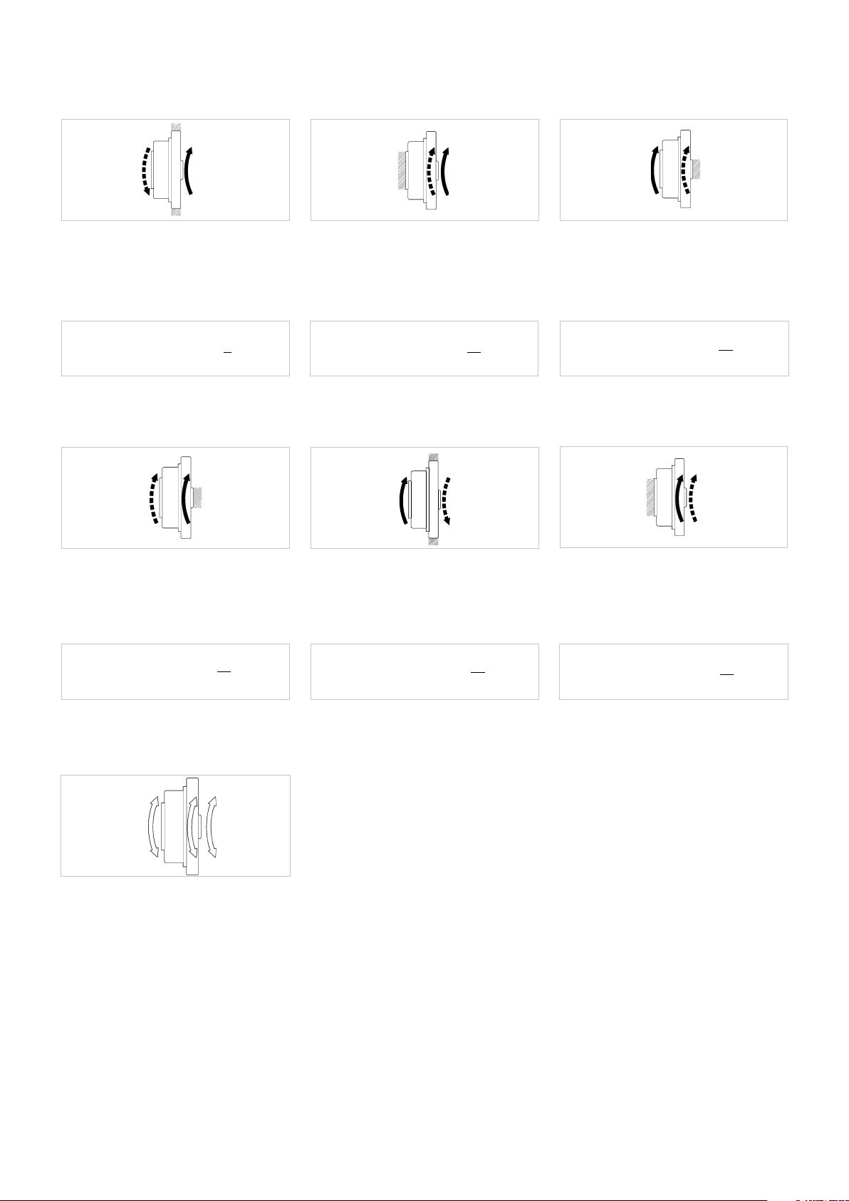
Assembly
During assembly the following general points should be considered:
The gear components have to be centred accurately within and relative to the housing.
First of all, the Flexspline and Circular Spline must be fixed. To ensure a centred position of the Circular Spline, the fastening
screws should be tightened crosswise using successively increased torque. Only then should the Wave Generator be inserted
into the Flexspline, as shown in illustration 38.1.
Caution: The assembly of the Wave Generator must be executed in the direction of the arrow. During the insertion of the Wave
Generator into the Flexspline the Flexspline adopts the elliptical shape of the Wave Generator.
Illustration 38.1
The assembly of the Wave Generator must be executed in the direction of the arrow.
Illustration 38.2
Wrong (Dedoidal) Right
38 1019658 11/2014
Page 39

Correct assembly of component sets may be checked in one of four ways:
Illustration 39.1
Flexspline deflection
concentric
Right
Flexspline deflection
1 Revolution (Input)
dedoidal
Wrong
• By visual observation, if the tooth mesh is exposed.
• In case the gearing is not visible, the input shaft can be rotated by hand. Uneven rotation suggests dedoidal tooth mesh.
• If the Wave Generator is connected to a motor, an unusually high motor current indicates dedoidal tooth mesh.
• A dial gauge can be inserted through an access hole near the Circular Spline to touch the surface of the Flexspline. A
quasi sinusoidal deflection during one revolution of the Flexspline indicates correct assembly as shown in illustration 39.1.
391019658 11/2014
Page 40

5.4 Recommended Tolerances for Assembly
In order for the new features of Harmonic Drive® Units to be exploited fully, it is essential that the tolerances according to
table 40.1 are observed for the input assembly.
Illustration 40.1
Recommended shaft tolerances h6Recommended shaft tolerances h6 or H6 Recommended housing tolerances H7
Table 40.2 [mm]
Size 14 17 20 25 32 40 45 50 58
a
b 0.016 0.021 0.024 0.035 0.042 0.048 0.053 0.057 0.062
c 0.015 0.018 0.019 0.022 0.022 0.024 0.027 0.030 0.032
d 0.011 0.015 0.017 0.024 0.026 0.026 0.027 0.028 0.031
e 0.011 0.015 0.017 0.024 0.026 0.026 0.027 0.028 0.031
f
g
0.011 0.012 0.013 0.014 0.016 0.016 0.017 0.018 0.020
0.017
(0.008)
0.030
(0.016)
0.020
(0.010)
0.034
(0.018)
0.024
(0.012)
0.044
(0.019)
0.024
(0.012)
0.047
(0.022)
0.024
(0.012)
0.050
(0.022)
0.032
(0.012)
0.063
(0.024)
0.032
(0.013)
0.065
(0.027)
0.032
(0.015)
0.066
(0.030)
0.032
(0.015)
0.068
(0.033)
The values in brackets are the recommended tolerances for component sets featuring a Wave Generator without Oldham coupling. The Oldham coupling
serves to compensate for eccentricity of the input shaft and is available in the standard version. For the direct mounting of a Wave Generator without
Oldham coupling (optional) on a motor shaft, the shaft tolerances should fulfill the DIN 42955 R standard.
40 1019658 11/2014
Page 41

5.5 Wave Generator Components
Illustration 41.1 shows a standard Wave Generator with Oldham Coupling.
Illustration 41.1
1)
2)
3)
7)
6)
4)
5)
Wave Generator Modifications
1) Ball Separator
2) Wave Generator bearing
3) Wave Generator plug
4) Insert
5) Thrust washers
6) Snap ring
7) Wave Generator hub
HFUS component sets have to compensate for runout of the motor shaft by default an Oldham coupling,
see illustration 41.2.
Principle of an Oldham Coupling
Illustration 41.2
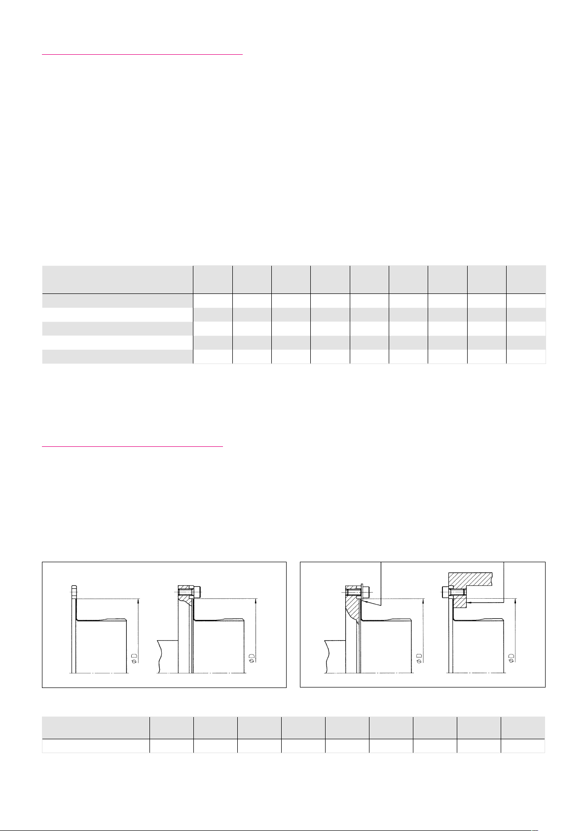
5.6 Bore Diameter for Solid Wave Generators
If a large-bore Wave Generator or an input coupling completely free of backlash is required, the Oldham coupling may
be removed and the input shaft can be attached directly to the Wave Generator plug. This is the so called “Solid Wave
Generator” configuration. The Wave Generator bore may be enlarged or splined to accept a hollow shaft or a splined shaft.
The maximum allowable bore diameter, with or without keyway or splines, is given in table 42.2. Use of a Solid Wave
Generator demands tighter tolerances for the motor shaft and housing, as described in the section “Design Guidelines/
Assembly Tolerances” for the selected product.
411019658 11/2014
Page 42

Maximum Bore Diameter Without Oldham Coupling
Illustration 42.1
Table 42.2
Size 14 17 20 25 32 40 45 50 58
L
for key to DIN 6885 T1 12 13 17 22 28 34 39 44 50
W
L 17 20 23 28 36 42 47 52 60
[mm]
5.7 Lubrication
At the time of delivery, the gears are conserved with preservation oil. The characteristics of the lubricating grease and oil
types approved by Harmonic Drive® are not changed by mixing with the preservation oil. It is therefore not necessary to
remove the preservation oil completely from the gear components. However, the mating surfaces must be degreased before
the assembly.
5.7.1 Grease Lubrication
Amount of Grease
Table 42.3 includes the recommendations by Harmonic Drive® for standard applications amounts of grease. Special applications
may possibly require special lubricants and amounts of grease. If in doubt please contact the Harmonic Drive AG.
Table 42.3
Size 8 11 14 17 20 25 32 40 45 50 58 65 80 90 100
Standard grease quantity
Additionally required grease quantity
for operation with Wave Generator
above
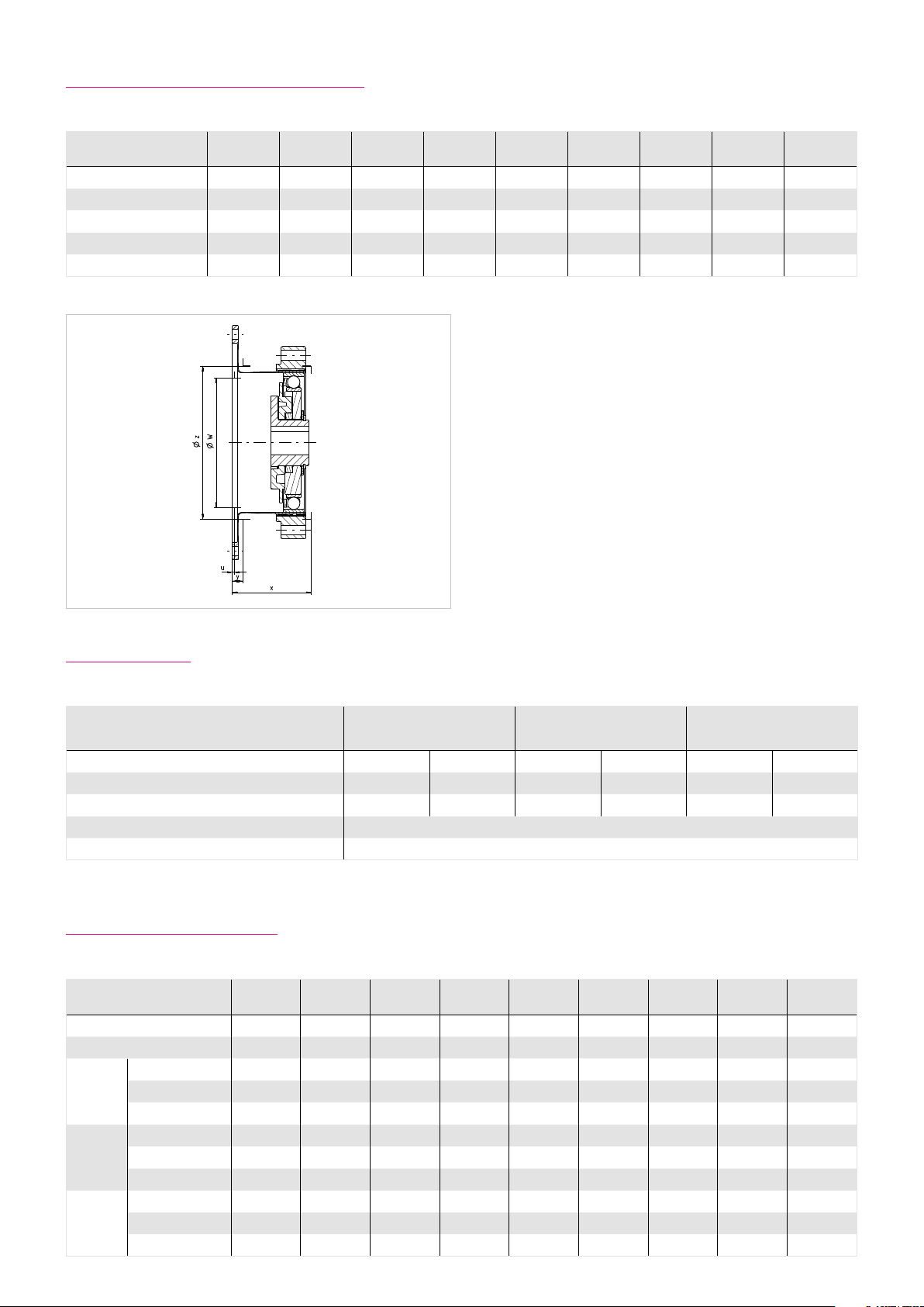
Dimensions
(see illustration 43.1)
Table 42.4
Ordering code Available packaging
Special grease SK-1A. SK-2 0.5; 2.5; 16
Special grease 4BNo.2 0.5; 2; 16
ca. [g] 1.8 3.5 5.5 10 16 40 60 130 180 260 360 440 850 990 1200
3
ca. [cm
] 2 4 6 11 18 44 66 143 198 286 396 484 935 1089 1320
ca. [g] 1 2 2 3 4 6 14 27 54 90 108 141 259 333 400
3
ca. [cm
] 1 2 2 3 4 7 16 30 60 100 120 155 285 366 440
ca. [mm] 1.5 2 3 4 4.5 5.5 7 9.5 11 12 13.5 15 18 20.5 22.5
[kg]
42 1019658 11/2014
Page 43
Grease Lubrication
Illustration 43.1 shows the areas to be lubricated, see also table 44.1. During operation, the 4BNo.2 grease becomes relatively
liquid. Therefore the gear must be sealed as for oil lubrication, when this grease is used. If required, please ask Harmonic Drive®
for further information.
Illustration 43.1
The required amount of grease is dependent on the size and the operating position of the gear.
The operating positions “Wave Generator above” or “Wave Generator below” refer to the relative position of the
Wave Generator to Flexspline flange, see illustration 43.2
Illustration 43.2
Operating Positions
Wave Generator below
Wave Generator vertical
Wave Generator above
Operation mainly with Wave Generator in vertical position or below
The supplied grease quantity is calculated for a Unit operating mainly with Wave Generator in vertical position or below.
See table 44.1.
Operation mainly with Wave Generator above
If the gear is mainly operated with Wave Generator above additional grease must be supplied above the Wave Generator,
see illustration 43.3 and table 44.1.
Illustration 43.3
If the units are used mainly with Wave
Generator above, then additional grease
lubrication is necessary.
431019658 11/2014
Page 44

5.7.2 Grease Reservoir
For assembly please ensure that the grease reservoir is filled up with grease (dimension c and ø d in table 44.1 and
illustration 44.2).
Table 44.1
Size 14 17 20 25 32 40 45 50 58
ø a 38 45 53 66 86 106 119 133 154
b 14.6 16.4 17.8 19.8 23.2 28.6 31.9 34.2 40.1
c* 1 1 1.5 1.5 1.5 2 2 2 2.5
c** 3 3 4.5 4.5 4.5 6 6 6 7.5
ø d 31 38 45 56 73 90 101 113 131
e 1.7 2.1 2 2 2 2 2.3 2.5 2.9
ø f 16 26 30 37 37 45 45 45 56
* Horizontal and Vertical - Wave Generator below
** Vertical - Wave Generator above
Illustration 44.2
Maximum centering length
Countersink for
mounting bolt heads
5.7.3 Grease Change
To change the grease the component set should be completely disassembled and cleaned before regreasing. Fresh grease
should be applied generously to the inside of the Flexspline, the Wave Generator bearing, the Oldham coupling and the teeth
of the Circular Spline and Flexspline.
In illustration 44.3, the grease change interval depending on the grease temperature is given. The number of allowable revolutions of the input shaft which represents the grease change interval can be estimated as shown in the example. This means,
that for a temperature of SK-1A or SK-2 grease of 40° C a change should take place after approx. 8.5 x 10⁸ revolutions of the
input shaft. All grease change data refers to rated speed and rated torque.
Illustration 44.3
1E+10
Flexolub A1
1E+09
Equation 44.4
3
T
.
GTn
(
r
)
T
av
L
= L
GT
L
= Number of Wave Generator revolutions until grease change
GT
L
= see diagram
GTn
Tr = Rated torque
Tav = Average torque
Number of WG revolutions
1E+08
4B No. 2
SK1A, SK2
20 40 60 80 100 120 140
Grease Temperature [°C]
44 1019658 11/2014
Page 45

5.7.4 Gears with Oil Lubrication
Harmonic Drive® Units with oil lubrication are generally customer-specific solutions. Please follow the notes given on the
confirmation drawing and refer to table 33.2 for allowed oil types. The oil temperature during operation must not exceed
90° C. Oil must be filled into the unit by the customer as the standard delivery does not include any oil lubricant.
Oil Quantity
The values specified in the confirmation drawing include the valid oil quantities to fill in. The oil quantity defined
on the confirmation drawing must be obeyed in any case. Too much oil results in excessive heat production and
early wear due to the thermal destruction of the oil. If the oil level is too low, this may lead to early wear as a result
of lubricant deficiency. See illustration 45.1 and table 45.3.
Illustration 45.1
Operating Positions
Wave Generator above Wave Generator perpendicular Wave Generator below
B = Oil level
Table 45.2
Size
Liter 0.01 0.02 0.03 0.07 0.13 0.25 0.32 0.4 0.7
Size 14 17 20 25 32 40 45 50 58
A 10 12 14 17 24 31 35 38 44
B 2.5 3 3 5 7 9 10 12 13
14 17 20 25 32 40 45 50 58
A = Oil level
Minimum amount of oil
Oil levels
B = Oil level
[mm]Table 45.3
The required oil quantity is dependent on the design. Therefore, the quantity specified in the drawing/service manual of the
machine is decisive for the oil quantity to fill in. Please also consider illustration 45.1 and table 45.3. The defined oil levels must
be obeyed in any case. Too much oil results in excessive heat production and early wear due to thermal destruction of the oil.
If the oil level is too low, this may lead to early wear as a result of lubricant defiency.
When the gear is to be used with the Wave Generator above or below, special consideration must be given because even small
changes of the oil level affect the churning losses.
451019658 11/2014
Page 46

5.7.5 Lubrication Holes
Example of pressure compensation design for vertical installation with Wave Generator up.
Illustration 46.1
5.8 Preparation for Assembly
Assembly Preparation
The gear assembly must be carried out very carefully and within a clean environment. Please make sure that during the
assembly procedure no foreign particles enter the gear.
General information
Clean, degrease and dry all mating surfaces to ensure an adequate coefficient of friction. The values given here are valid for
12.9 quality screws which must be tightened by means of a torque wrench. Locking devices such as spring washers or toothed
washers should not be used.
Auxiliary materials for assembly
For the assembly, we recommend the application of the following auxiliary materials or the use of those with similar
characteristics. Please pay attention to the application guidelines given by the manufacturer. Auxiliary materials must
not enter the gear.
Surface sealing
• Loctite 5203
• Loxeal 28-10
Recommended for all mating surfaces, if the use of o-ring seals is not intended.
Screw fixing
• Loctite 243
This adhesive ensures that the screw is fixed and also provides a good sealing effect. Loctite 243 is recommended for all
screw connections.
Assembly paste
• Klüber Q NB 50
Recommended for o-rings which may come out of the groove during the assembly procedure. Before starting with the
assembly you should spread some grease (which you can take from the gear) on all other o-rings.
Adhesives
• Loctite 638
Apply Loctite 638 to the connections between motor shaft and Wave Generator. You should make use of it only if this is
specified in the confirmation drawing.
46 1019658 11/2014
Page 47

5.9 Assembly
The assembly must take place basically without impact. The assembly instructions of the machine manufacturer are to be
considered. All screws must be tightened crosswise in 3 steps to the prescribed torque.
Assembly procedure
The assembling method of the gear depends strongly on the design details. Thus, this assembly manual only comprises
standard information.
Basically first the Circular Spline (CS) and Flexspline (FS) should to be mounted and screwed down. The assembly of these two
components can take place in any order.
The Wave Generator (WG) should be shifted at last into the pre-mounted components Flexspline/Circular Spline. If the
assembling sequence described above cannot be observed please ask Harmonic Drive® whether in the concrete case another
sequence is admissible.
Note:
Before the Wave Generator is set in position, the Circular Spline fixing screws must be tightened. Otherwise the Circular
Spline would deform under the pre-load initiated by the Wave Generator. This could cause the gear to run roughly.
For the planning of the assembly sequence it may be helpful to know the max. diameter of the Wave Generator.
See illustration 47.2. In table 47.1 the diameters of the Wave Generator main axes are indicated.
Table 47.1
Size 14 17 20 25 32 40 45 50 58
ca. ∅ Wave Generator
- Main axis
Illustration 47.2
36 43 50 63 82 100 114 125 146
∅ Wave Generator
- Main axis
[mm]
471019658 11/2014
Page 48
5.9.1 Assembly of the Circular Spline
The Circular Spline must not be bended during the assembly. Therefore it is particularly important that the mounting base
of the Circular Splineis absolutely even and that the mounting base centering causes neither clamping strength nor radial
clearance.
Explanation:
A slightly deformed Circular Spline can result in irregular running characteristics. If a deformation of the Circular Spline is
suspected it should be verified whether the Circular Spline can rotate freely within its locating bore in the machine housing
without any friction. Even slight friction may be an indicator for a possible radial deformation of the Circular Spline. In this
case the tolerances of the machine housing and the Circular Spline must be checked.
For grease lubrication the Circular Spline teeth must be lubricated in accordance with illustration 43.1. For the correct
mounting please also see illustration 39.1.
Circular Spline Screws
Table 48.1
Size 14 17 20 25 32 40 45 50 58
Number of screws 6 12 12 12 12 12 12 12 12
Size of screws M3 M3 M3 M4 M5 M6 M8 M8 M10
Pitch circle diameter [mm] 44 54 62 75 100 120 140 150 175
Clamping torque [Nm] 2.0 2.0 2.0 4.5 9.0 15.3 37 37 74
Torque transmitting capacity [Nm] 54 131 147 314 675 1150 2440 2620 4820
The tables are valid for completely degreased pads (friction coefficient µk = 0.15) and metric socket head cap screws according to EN ISO 4762 in 12.9 quality,
untreated, oiled, with µtotal = 0.12.
5.9.2 Assembly of the Flexspline
Care must be taken that the heads of clamping bolts, washers, nuts or clamping rings do not interfere with local flexing of
the Flexspline. Otherwise eventual failure will result.
For this reason, fastening elements must not enter the region which is marked by ø D. Please refer to illustration 48.2.
Illustration 48.2 Illustration 48.3
Right Wrong
Table 48.4
Size 14 17 20 25 32 40 45 50 58
ø D 48 60 70 88 114 140 158 175 203
[mm]
48 1019658 11/2014
Page 49

5.9.3 Flexspline Screws
The connection of the Flexspline to the output is normally realised with screws or in case of higher torques with screws and
pins. If the load is below the limit for repeated peak torque the connection is carried out with screws as shown in table 49.1.
Flexspline Screws
Table 49.1
Size 14 17 20 25 32 40 45 50 58
Number of screws
Size of screws
Pitch circle diameter
Pitch circle diameter
1)
2)
[mm] 64 74 84 102 132 158 180 200 226
[mm] 54 66 76 96 124 152 170 190 218
8 12 12 12 12 12 18 12 16
M3 M3 M3 M4 M5 M6 M6 M8 M8
Screw tightening torque [Nm] 2.0 2.0 2.0 4.5 9.0 15.3 15.3 37 37
Transmittable torque
Transmittable torque
1)
Modified version
2)
Standard version with compact flexspline
1)
2)
[Nm] 104 176 206 427 897 1507 2573 3486 5262
[Nm] 88 157 186 402 843 1450 2430 3312 5076
The tables are valid for completely degreased pads (friction coefficient µk = 0.15) and metric socket head cap screws according to EN ISO 4762 in 12.9 quality,
untreated, oiled, with µtotal = 0.12.
491019658 11/2014
Page 50
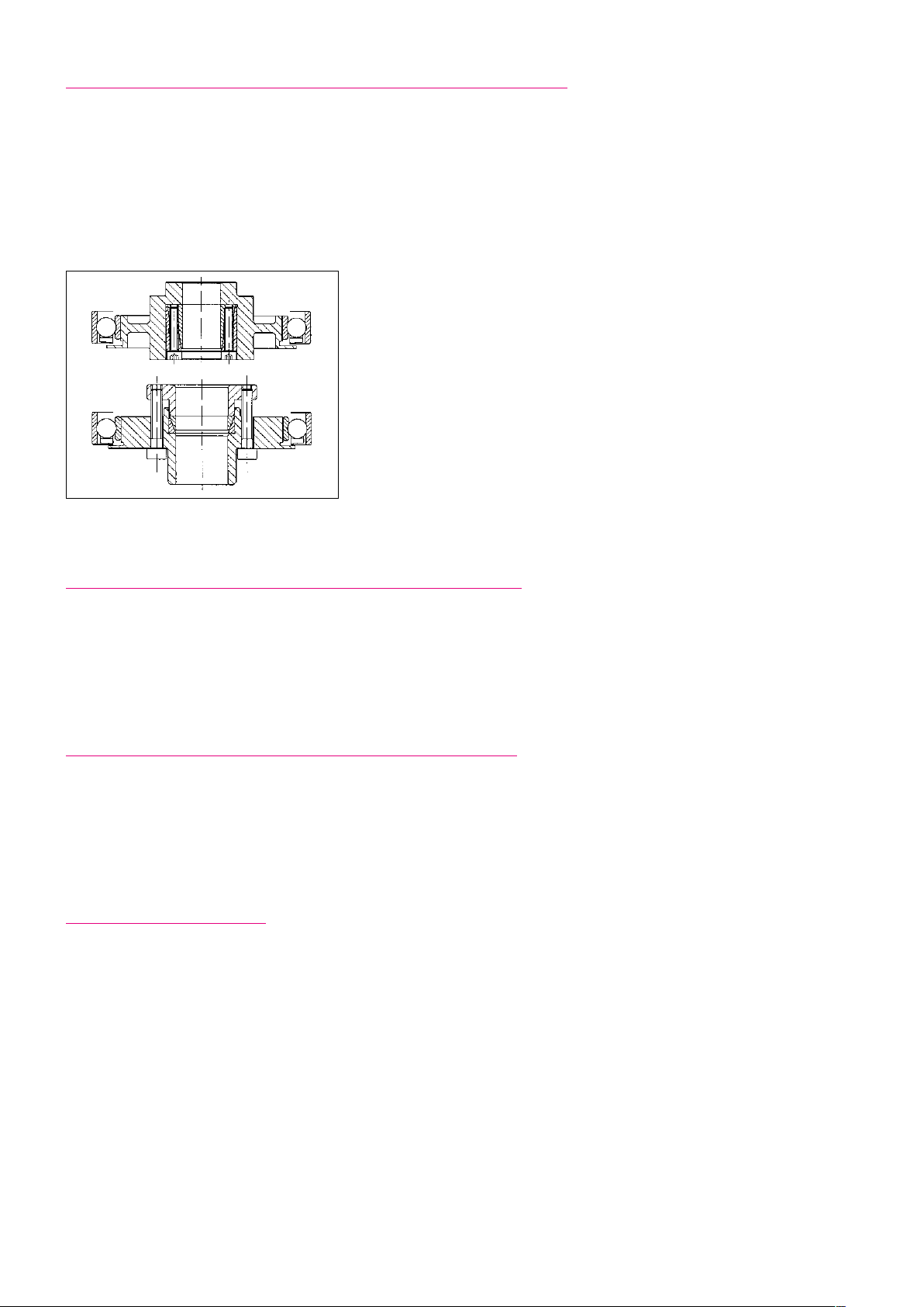
5.9.4 Assembly of the Wave Generator to the Input Shaft
Before or after the assembly to the input shaft the Wave Generator is to be lubricated according to section 5.7. During the
assembly the axial mounting position indicated on the catalogue/confirmation drawing is to be considered.
When a clamping element is used please thighten the clamping element screws crosswise and in five steps up to the torque
indicated on the drawing (alternatively: manufacturer information), see also illustration 50.1. When the Wave Generator hub is
glued to the input shaft please consider section 5.8..
Illustration 50.1
Design examples for Solid Wave Generator
with clamping element
5.9.5 Check before Assembly of the Wave Generator
Final check of position of the Wave Generator. For some clamping elements an axial movement may occur during tightening.
Please take account of this effect when positioning the Wave Generator on the shaft.
Check whether the Wave Generator is lubricated in accordance with section 5.7. When the gear is oil lubricated, fill in the
prescribed oil quantity.
5.9.6 Final Check of Position of the Wave Generator
When the Wave Generator is assembled into the Flexspline please consider that the parts must not be tilted during assembly.
By parallel assembly it is ensured that the teeth of Flexspline and Circular Spline mesh symmetrically.
Alternatively the assembly can be executed during slowly rotation of the input shaft (n < 10 rpm). This method eases the
assembly.
5.9.7 Assembly Control
Very rarely, an eccentric tooth mesh, called dedoidal, may occur (see illustration 38.2). The correct assembly can be checked as
follows:
• Check the running behaviour by rotating the input shaft (in case of types with input shaft). Alternatively you may rotate
the output flange. If you notice torque variations these may be caused by eccentric tooth mesh.
• Check the running behaviour and the motor current while the motor is rotating. Strong fluctuations in the motor current
and/or an excessive no-load current may be the result of an eccentric tooth mesh.
In case of a dedoidal assembly you can avoid permanent damage to the gear if the wrong installation is recognized by means
of the above mentioned inspection. The problem can be solved by disassembling the gear followed by a new assembly.
50 1019658 11/2014
Page 51

6. Glossary
6.1 Technical Data
AC Voltage constant kEM [V
Eective value of the induced motor voltage measured at the motor terminals at a speed of 1000 rpm and an operating
temperature of 20° C.
/ 1000 rpm]
rms
Ambient operating temperature [°C]
The intended operating temperature for the operation of the drive.
Average input speed (grease lubrication) n
Maximum permissible average gear input speed for grease lubrication.
Average input speed (oil lubrication) n
Maximum permissible average gear input speed for oil lubrication.
av (max)
av (max)
[rpm]
[rpm]
Average torque TA [Nm]
When a variable load is applied to the gear, an average torque should be calculated for the complete operating cycle.
This value should not exceed the specified TA limit.
Backlash (Harmonic Planetary gears) [arcmin]
When subjected to the rated torque, Harmonic Planetary
gears display characteristics shown in the hysteresis curve.
When a torque is applied to the output shaft of the gear
with the input shaft locked, the torque-torsion relationship
can be measured at the output. Starting from point 0 the
graph follows successive points A-B-A-B-A A where the value
B-B is defined as the backlash or hysteresis.
Hysteresis loss/
Backlash
Torsion
φ
Torque T +T
N
Brake closing time tC [ms]
Delay time to close the brake.
Brake current to hold I
Current for applying the brake.
Brake current to open I
Current required to open the brake.
HBr
OBr
[ADC]
[ADC]
Brake holding torque TH [Nm]
Torque the actuator can withstand when the brake is applied, with respect to the output.
Brake opening time tO [ms]
Delay time for opening the brake.
Brake voltage UBr [VDC]
Terminal voltage of the holding brake.
T
= Rated torque
N
φ = Output angle
511019658 11/2014
Page 52

Collision torque TM [Nm]
In the event of an emergency stop or collision, the Harmonic Drive® Gearing may be subjected to a brief collision torque.
The magnitude and frequency of this collision torque should be kept tom a minimum and under no circumstances should
the collision torque occur during the normal operating cycle.
Continuous stall current I0 [A
rms
]
Eective value of the motor phase current to produce the stall torque.
Continuous stall torque T0 [Nm]
Allowable actuator stall torque.
Demagnetisation current IE [A
rms
]
Current at which rotor magnets start to demagnetise.
Dynamic axial load F
A dyn (max)
[N]
With bearing rotating this is the maximum allowable axial load, with no additional radial forces or tilting moments applied.
Dynamic load rating C [N]
Maximum dynamic load that can be absorbed by the output bearing before permanent damage may occur.
Dynamic radial load F
R dyn (max)
With bearing rotating this is the maximum allowable radial load, with no additional axial forces or tilting moments applied.
[N]
Dynamic tilting moment M
dyn (max)
[Nm]
With the bearing rotating this is the maximum allowable tilting moment, with no additional axial forces or radial forces
applied.
Electrical time constant τe [s]
The electrical time constant is the time required for the current to reach 63% of its final value.
Hollow shaft diameter dH [mm]
Free inner diameter of the continuous axial hollow shaft.
Inductance (L-L) L
[mH]
L- L
Terminal inductance calculated without taking into account the magnetic saturation of the active motor parts.
Lost Motion (Harmonic Drive® Gearing) [arcmin]
Harmonic Drive® Gearing exhibits zero backlash in the teeth.
Lost motion is the term used to characterise the torsional
stiness in the low torque region.
The illustration shows the angle of rotation ϕ measured
against the applied output torque as a hysteresis curve, with
the Wave Generator locked. The lost motion measurement of
the gear is taken with an output torque of about ± 4% of the
rated torque.
Lost Motion
φ
Torsion
φ
; φ
1‘
2‘
φ1 ; φ
2
Torque T
N
~ +4%T
N
~ -4%T
52 1019658 11/2014
Page 53

Maximum DC bus voltage U
The maximum DC bus power supply for the correct operation of the actuator. This value may only be exceeded for a short
period during the braking or deceleration phase.
DC (max)
[VDC]
Maximum hollow shaft diameter d
For gears with a hollow shaft, this value is the maximum diameter of the axial hollow shaft.
Maximum input speed (grease lubrication) n
Maximum allowed input speed for gearing with grease lubrication.
Maximum input speed (oil lubrication) n
Maximum allowed input speed for gearing with oil lubrication.
Maximum motor speed n
The maximum allowable motor speed.
Maximum output speed n
The maximum output speed. Due to heating issues, this may only be momentarily applied during the operating cycle. The
maximum output speed can occur any number of times as long as the rated speed is greater than the permissible continuous
operation calculated in the duty cycle.
Maximum output torque T
Specifies the maximum allowable acceleration and deceleration torques. For highly dynamic processes, this is the maximum
torque available for a short period. The maximum torque can be parameterized by the control unit where the maximum
current can be limited. The maximum torque can be applied as often as desired, as long as the average torque is within the
permissible continuous operation calculated in the duty cycle.
max
max
max
[rpm]
[rpm]
[Nm]
H (max)
[mm]
in (max)
in (max)
[rpm]
[rpm]
Maximum power P
Maximum power output.
max
[W]
Mechanical time constant τm [s]
The mechanical time constant is the time required to reach 63% of its maximum rated speed in a no-load condition.
Momentary peak torque TM [Nm]
In the event of an emergency stop or collision, the Harmonic Drive® Gearing may be subjected to a brief collision torque.
The magnitude and frequency of this collision torque should be kept tom a minimum and under no circumstances should
the momentary peak torque occur during the normal operating cycle.
Moment of inertia J [kgm²]
Mass moment of inertia at motor side.
Moment of inertia Jin [kgm²]
Mass moment of inertia of the gearing with respect to the input.
Moment of inertia J
Mass moment of inertia with respect to the output.
[kgm2]
out
531019658 11/2014
Page 54

Motor terminal voltage (Fundamental wave only) UM [V
Required fundamental wave voltage to achieve the specified performance. Additional power losses can lead to restriction
of the maximum achievable speed.
rms
]
Number of pole pairs p
Number of magnetic pole pairs on the rotor of the motor.
Oset R [mm]
Distance between output bearing and contact point of load.
Pitch circle diameter dp [mm]
Pitch circle diameter of the output bearing.
Protetcion IP
The degree of protection according to EN 60034-5 provides suitability for various environmental conditions.
Rated current IN [A]
Rms value of the sinusoidal current when driven at rated torque and rated speed.
Rated motor speed nN [rpm]
The motor speed which can be continuously maintained when driven at rated torque TN, when mounted on a suitably
dimensioned heat sink.
Rated power PN [W]
Output power at rated speed and rated torque.
Rated speed nN [rpm]
The output speed which can be continuously maintained when driven at rated torque TN, when mounted on a suitably
dimensioned heat sink.
Rated torque TN [Nm], Servo
The output torque which can be continuously transmitted when driven at rated input speed, when mounted on a suitably
dimensioned heat sink.
Rated torque TN [Nm], Mechanic
The rated torque is a reference torque for the calculation of the gear life. When loaded with the rated torque and running
at rated speed the gear will reach the average life L50. The rated torque TN is not used for the dimensioning of the gear.
Rated voltage UN [V
Supply voltage for operation with rated torque and rated speed.
rms
]
Ratio i [ ]
The ratio is the reduction of input speed to the output speed.
Note for Harmonic Drive® transmission: The standard version of the wave is generating the drive element, the output element
of the flexspline and the circular Spline is fixed to the housing. Since the direction of rotation of the drive (Wave Generator) to
output reverses (Flexspline), a negative ratio for results Calculations in which the direction of rotation must be considered.
54 1019658 11/2014
Page 55

Repeatability [arcmin]
The repeatability of the gear describes the position dierence measured during repeated movement to the same
φ2
x/2
φ1
φ7
x
x/2
desired position from the same direction. The repeatability
is defined as half the value of the maximum dierence
measured, preceded by a ± sign.
Repeatability = ±x /2 = ±x /2
Repeatable peak torque TR [Nm]
Specifies the maximum allowable acceleration and braking torques. During the normal operating cycle the repeatable peak
torque TR should be not be exceeded.
Resistance (L-L, 20° C) R
L- L
[Ω]
Winding resistance measured between two conductors at a winding temperature of 20° C.
Size
1) Actuators / Gears with Harmonic Drive® gears or Harmonic Planetary gears
The frame size is derived from the pitch circle diameter of the gear teeth in inches multiplied by 10.
2) CHM Servo motor series
The size of the CHM servo motors is derived from the stall torque in Ncm.
3) Direct drives from the TorkDrive® series
The size of the TorkDrive® series is the outer diameter of theiron core of the stator.
Static load rating C0 [N]
Maximum static load that can be absorbed by the output bearing before permanent damage may occur.
Static tilting moment M0 [Nm]
With the bearing stationary this is the maximum allowable radial load, with no additional axial forces or tilting moments
applied.
Tilting moment stiness KB [Nm/arcmin]
The tilting angle of the output bearing at an applied moment load.
Torque constant (motor) kTM [Nm/A
Quotient of stall torque and stall current.
Torque constant (output) k
Quotient of stall torque and stall current, taking into account the transmission losses.
[Nm/A
Tout
rms
rms
]
]
551019658 11/2014
Page 56

Torsional stiness
(Harmonic Drive® Gears) K3 [Nm/rad]
The amount of elastic rotation at the output for a given
torque and the Wave Generator blocked. The torsional
stiness K3 describes the stiness above a defined reference
torque where the stiness is almost linear. Values below
this torque can be requested or found on our web site.
The value given for the torsional stiness K3 is an average that has been determined during numerous tests. The
limit torques T1 and T2 and calculation example for the total
torsional angle Gesamtverdrehwinkels can be found in the
secondary technical documentation.
Torsional stiness
(Harmonic Planetary gears) K [Nm/rad]
The amount of elastic rotation at the output for a given
torque and blocked input shaft. The torsional rigidity of the
Harmonic Planetary gear describes the rotation of the gear
above a reference torque of 15% of the rated torque. In this
area the torsional stiness is almost linear.
Torsion
φ
K
3
φ2
φ1
, K2, K3 = Torsional stiness, w = Output angle
K
1
φ1 = Torsion angle, with output torque T
φ2 = Torsion angle, with output torque T
K
2
K
1
Torque T
0
T
T
1
2
1
2
TN = Rated torque
φ = Output angle
Transmission accuracy [arcmin]
The transmission accuracy of the gear represents a linearity
error between input and output angle. The transmission accuracy is measured for one complete output revolution using
a high resolution measurement system. The measurements
are carried out without direction reversal. The transmission
Transmission
accuracy is defined as the sum of the maximum positive and
accuracy
negative dierences between theoretical and actual output
rotation angle.
Accuracy
360° Output
angle
Weight m [kg]
The weight specified in the catalog is the net weight without packing and only applies to standard versions.
56 1019658 11/2014
Page 57

6.2 Labelling, Guidelines and Regulations
CE-Marking
With the CE marking, the manufacturer or EU importer declares in accordance
with EU regulation, that by axing the CE mark the product meets the applicable
requirements in the harmonization legislation established the Community.
REACH Regulation
REACH is a European Community Regulation on chemicals. REACH stands for
Registration, Evaluation, Authorization and Restriction of Chemicals.
RoHS EU Directive
The RoHS EU Directive on the restriction of the use of certain hazardous
substances in electrical and electronic equipment.
REACH
Verordnung
Nr. 1907/2006
571019658 11/2014
Page 58

Deutschland
Harmonic Drive AG
Hoenbergstraße 14
65555 Limburg/Lahn
T +49 6431 5008-0
F +49 6431 5008-119
info@harmonicdrive.de
www.harmonicdrive.de
Subject to technical changes.
11/2014 1019658
 Loading...