

Harmonic PWRLink II 4800T Product Manual

PWRLink™ II 4800T Series
Optical Transmitter
Product Manual
Manual Part No.: 700-0051934
Rev A
February 2002
PWRLink II 4800T Optical Transmitter Product Manual
ATTENTION
AVERTISSEMENT
ACHTUNG
Pursuant to the pertinent sections of Title 21, (United States) Code of Federal Regulations
(CFR), Chapter I, Subchapter J, and administered by the Center for Devices and Radiological
Health (CDRH), operation under the Food and Drug Administration (FDA), this product,
which produces or receives an optical signal, composed of Laser Radiation, complies with 21
CFR Chapter I, Subchapter J, as applicable to Class I Laser Products with a Class 3B Hazard.
Note!
This laser warning is included in all Harmonic manuals. The intended use of all Harmonic
products, including those products that do not contain lasers, are in systems that contain lasers.
Therefore this warning is important for the safety of all persons operating or maintaining the
equipment.
INTENDED MEANING
SIGNIFICATION
BEDEUTUNG
DANGER: Invisible Laser Radiation, when open or when operating with
fiber disconnected. AVOID DIRECT EXPOSURE TO THE BEAM. Never
operate unit with a broken fiber or with a fiber connector disconnected.
DANGER: Les rayons laser sont invisibles à l´oeil. NE PAS S´EXPOSER
DIRECTEMENT AU FAISCEAU. Ne jamais utiliser l´appareil lorsque la
fibre est interrompue ou un connecteur endommagé ou déconnecté.
VORSICHT: Unsichtbare Laserstrahlung, wenn Abdeckung geöffnet oder
Glasfaserkabel entfernt. DIREKTEN KONTAKT MIT DEM STRAGL
VERMEDIDEN. Das Gerät nicht einschalten, wenn das Glasfaserkabel
beschädigt oder nicht angelchlossen ist.
CAUTION: There are no user serviceable parts inside. Refer all servicing
to qualified service personnel. Other than those specific measurements,
adjustments and tests specified in the manual, make NO attempt to
modify or alter any circuit or assembly in any manner.
ATTENTION: Toute intervention sur cet équipement est formellement
déconseillée par le fabricant. En dehors de réglages décrits dans le
manuel, l´utilisateur doit contacter une personne qualifiée par le fabricant
pour toute modification ou réparation.
VORSICHT: Es sind keine zu wartenden Teile im Gerät, alle
Wartungsarbeiten nur von qualifiziertem Personal ausführen lassen. Ex
dürfen nur die im Handbuch spezifisch aufgeführten Messungen,
Justierungen und Tests vom Benutzer vorgenommen werden.Unter
keinen Umständen, dürfen Modifikationen oder Änderungen jeglicher
Art am Gerät unternommen werden.
INTERNATIONAL SYMBOL
SYMBOLE INTERNATIONAL
INTERNATIONALES SYMBOL
Copyright 2002 Harmonic Inc
Harmonic continues to improve and enhance all product designs. Specifications are subject to change without notice. Harmonic and logo design,
eXchange, MAXLink, METROLink, NETWatch, PWRBlazer, TRANsend, and “Redefining the Network” are trademarks of Harmonic Inc. YAGLink
and PWRLink are registered trademarks of Harmonic Inc. All other names are trademarks or registered trademarks of their respective owners.
RemotelyAnywhere is copyright © 3AM Laboratories PL.
.
Copyright © 2002 Harmonic Inc.

Table of Contents
Chapter 1 Overview
1.1 About This Manual . . . . . . . . . . . . . . . . . . . . . . . . . . . . . . . . . . . . . . . . . . . . . . 1-1
1.2 Description . . . . . . . . . . . . . . . . . . . . . . . . . . . . . . . . . . . . . . . . . . . . . . . . . . . . . 1-1
1.3 Applications . . . . . . . . . . . . . . . . . . . . . . . . . . . . . . . . . . . . . . . . . . . . . . . . . . . . 1-4
Chapter 2 Installing the PWRLink II Transmitter
2.1 Receiving and Inspecting . . . . . . . . . . . . . . . . . . . . . . . . . . . . . . . . . . . . . . . . . 2-1
2.2 Installing the Transmitter Module. . . . . . . . . . . . . . . . . . . . . . . . . . . . . . . . . . 2-1
2.3 Connecting the Fiber Cable. . . . . . . . . . . . . . . . . . . . . . . . . . . . . . . . . . . . . . . . 2-3
2.4 Connecting the RF Broadband Input. . . . . . . . . . . . . . . . . . . . . . . . . . . . . . . . 2-3
2.5 Testing RF Signal Input . . . . . . . . . . . . . . . . . . . . . . . . . . . . . . . . . . . . . . . . . . . 2-4
Chapter 3 User Interface Options
3.1 HLP 4200WD Display . . . . . . . . . . . . . . . . . . . . . . . . . . . . . . . . . . . . . . . . . . . . 3-1
3.1.1 Transmitter Status . . . . . . . . . . . . . . . . . . . . . . . . . . . . . . . . . . . . . . . . . 3-5
3.1.2 Transmitter Setup . . . . . . . . . . . . . . . . . . . . . . . . . . . . . . . . . . . . . . . . . 3-5
3.1.3 Transmitter Adjustments . . . . . . . . . . . . . . . . . . . . . . . . . . . . . . . . . . . 3-5
3.1.4 Transmitter Alarms . . . . . . . . . . . . . . . . . . . . . . . . . . . . . . . . . . . . . . . . 3-5
3.2 NETWatch Site Controller. . . . . . . . . . . . . . . . . . . . . . . . . . . . . . . . . . . . . . . . . 3-5
3.3 Front Panel RF Adjustment. . . . . . . . . . . . . . . . . . . . . . . . . . . . . . . . . . . . . . . . 3-6
3.4 Front Panel LED Indicators. . . . . . . . . . . . . . . . . . . . . . . . . . . . . . . . . . . . . . . . 3-6
Chapter 4 Transmitter Setup
4.1 Factory-Optimized Settings . . . . . . . . . . . . . . . . . . . . . . . . . . . . . . . . . . . . . . . 4-2
4.1.1 Returning to Factory Settings . . . . . . . . . . . . . . . . . . . . . . . . . . . . . . . 4-2
4.2 Fine Tuning Each Transmitter . . . . . . . . . . . . . . . . . . . . . . . . . . . . . . . . . . . . . 4-3
4.3 Autosetup, Automatic Gain Control, and Manual Gain Control . . . . . . . . 4-3
4.3.1 Autosetup . . . . . . . . . . . . . . . . . . . . . . . . . . . . . . . . . . . . . . . . . . . . . . . . 4-4
4.3.2 Automatic Gain Control (AGC) and Manual Gain
Control (MGC) 4-6
4.4 Setup via HLP 4200WD Display . . . . . . . . . . . . . . . . . . . . . . . . . . . . . . . . . . . 4-7
4.4.1 Step-by-Step Setup Instructions . . . . . . . . . . . . . . . . . . . . . . . . . . . . . 4-7
4.4.2 Fine Tuning the Transmitter . . . . . . . . . . . . . . . . . . . . . . . . . . . . . . . . 4-8
4.4.3 Resetting the Transmitter to Factory Defaults . . . . . . . . . . . . . . . . . 4-8
4.5 Setup via NETWatch Site Controller. . . . . . . . . . . . . . . . . . . . . . . . . . . . . . . . 4-9
4.6 Setup via the Transmitter’s Front Panel Controls . . . . . . . . . . . . . . . . . . . . . 4-9
Chapter 5 Maintenance
5.1 Cleaning Fiber Optic Connectors. . . . . . . . . . . . . . . . . . . . . . . . . . . . . . . . . . . 5-1
5.1.1 Cleaning Patch Cord or Pigtail Fiber Optical Connectors . . . . . . . . 5-2
5.1.2 Cleaning Transmitter Module Optical Connectors . . . . . . . . . . . . . 5-2
5.2 Fan Replacement . . . . . . . . . . . . . . . . . . . . . . . . . . . . . . . . . . . . . . . . . . . . . . . . 5-3
PWRLink II 4800T Optical Transmitter Product Manual Rev A (2/02) i

Chapter 6 Troubleshooting
6.1 Troubleshooting . . . . . . . . . . . . . . . . . . . . . . . . . . . . . . . . . . . . . . . . . . . . . . . . . 6-1
6.2 In Case of Problems . . . . . . . . . . . . . . . . . . . . . . . . . . . . . . . . . . . . . . . . . . . . . . 6-1
6.3 Warranty Summary . . . . . . . . . . . . . . . . . . . . . . . . . . . . . . . . . . . . . . . . . . . . . . 6-2
6.4 Limitations of Warranty . . . . . . . . . . . . . . . . . . . . . . . . . . . . . . . . . . . . . . . . . . 6-2
6.5 Exclusive Remedies . . . . . . . . . . . . . . . . . . . . . . . . . . . . . . . . . . . . . . . . . . . . . . 6-2
Appendix A Technical Specifications
A.1 Link Performance . . . . . . . . . . . . . . . . . . . . . . . . . . . . . . . . . . . . . . . . . . . . . . . A-1
A.2 Optical Output . . . . . . . . . . . . . . . . . . . . . . . . . . . . . . . . . . . . . . . . . . . . . . . . . . A-2
A.3 RF Input . . . . . . . . . . . . . . . . . . . . . . . . . . . . . . . . . . . . . . . . . . . . . . . . . . . . . . . A-2
A.4 User Interface . . . . . . . . . . . . . . . . . . . . . . . . . . . . . . . . . . . . . . . . . . . . . . . . . . . A-3
A.5 Power Requirements . . . . . . . . . . . . . . . . . . . . . . . . . . . . . . . . . . . . . . . . . . . . . A-3
A.6 Environmental . . . . . . . . . . . . . . . . . . . . . . . . . . . . . . . . . . . . . . . . . . . . . . . . . .A-3
A.7 Physical . . . . . . . . . . . . . . . . . . . . . . . . . . . . . . . . . . . . . . . . . . . . . . . . . . . . . . . . A-4
A.8 Models Available . . . . . . . . . . . . . . . . . . . . . . . . . . . . . . . . . . . . . . . . . . . . . . . .A-4
Appendix B HLP 4200WD Menu Display
ii Copyright © 2002 Harmonic Inc.

1.1 About This Manual
This instruction manual is a complete guide to installation, configuration and
operation of PWRLink™ II 4800T series optical transmitters. The models that
are covered by this manual are listed in Appendix A, Section A.2.
• Chapter 1 provides a description of the PWRLink II transmitter.
• Chapter 2 describes the installation procedure.
• Chapter 3 introduces the user interfaces.
• Chapter 4 describes how to set up and configure the transmitter.
• Chapter 5 outlines maintenance procedures.
• Chapter 6 provides instructions on what to do in the event of problems.
• Appendix A provides complete technical specifications.
• Appendix B shows additional user interface details.
• Appendix C provides a list of Harmonic’s offices.
1
Overview
1.2 Description
The PWRLink II 4800T transmitter is a compact plug-in module designed for
use in the Harmonic HLP 4200 equipment platform. An HMC 4000 module
carrier is needed to mount the transmitter in the platform. Harmonic has
optimized the PWRLink II 4800T series family of transmitter modules for
high-performance transmission of RF broadband information over optical
fiber networks.
The PWL 4800T has the following key features:
• Transmission bandwidth from 45 MHz to 870 MHz
• Optical performance with 76 PAL (System B/G) analog channels plus
additional digital loading
• Internal monitoring and control using 32-bit microprocessor
• Local control of operating parameters—provided by the HLP 4200
platform
• Remote control and monitoring—provided by NETWatch Site Controller
• Autosetup feature that adjusts RF pad for optimum modulation
performance
• Automatic gain control and manual gain control modes of operation
PWRLink II 4800T Optical Transmitter Product Manual Rev A (2/02) 1–1
Overview
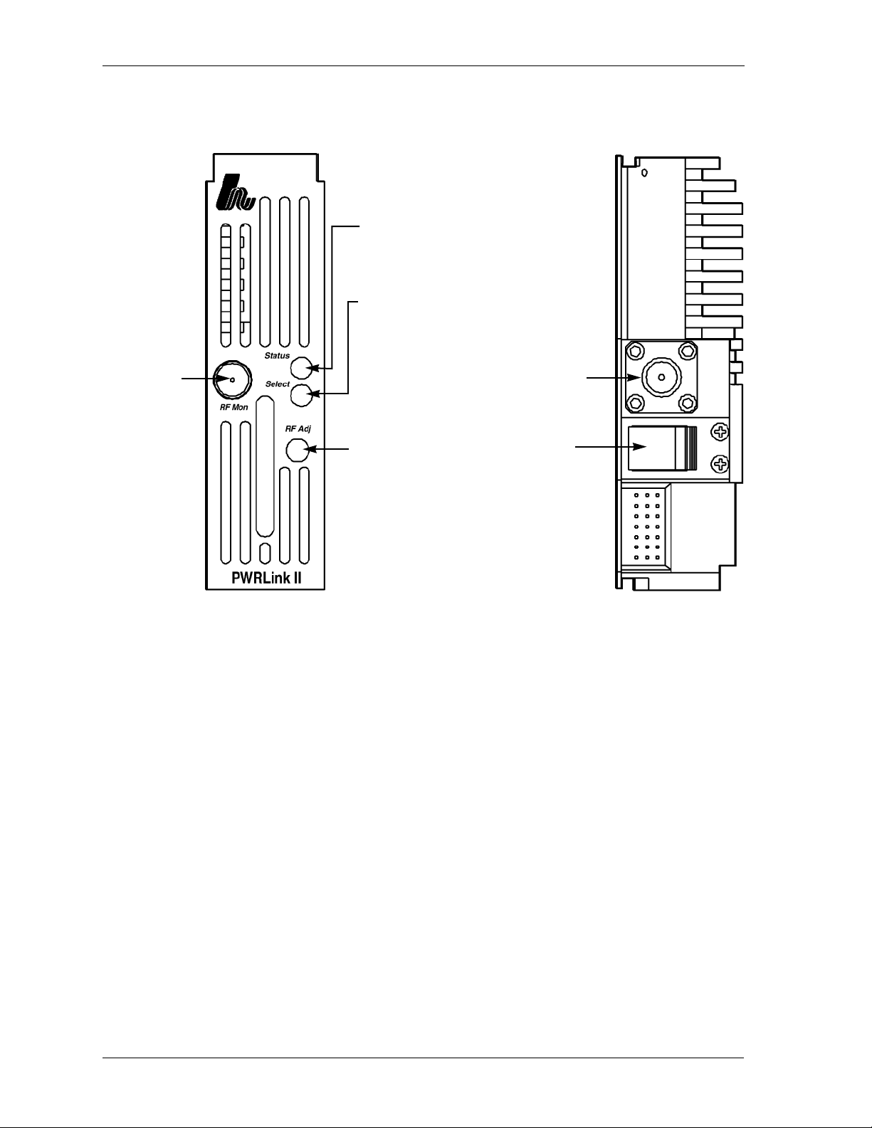
Figure 1-1 shows front and rear panel features of the PWL 4800T transmitter
module.
Status LED: Bi-state LED
illuminates green when the
module is functioning properly, or
red during an alarm or power up
Select LED: Yellow-colored LED
illuminates when the module is
selected through the front panel
display of the HLP 4200WD
RF Monitor:
Monitor point for
RF signal at the
transmitter input
RF In: Female
F connector
RF Pad Adjustment
PWL49FRP
Optical Out
PWL49REP
Figure 1-1. PWL 4800T front and rear panel features
Transmitter performance is optimized by combining state-of-the-art 1310 nm
DFB (distributed feedback) laser technology and patented pre-distortion
linearization circuitry. Harmonic has designed the PWRLink II family for
integration into networks with advanced element management systems; each
transmitter module employs a microprocessor-based communication and
monitoring architecture. Figure 1-2 is a block diagram of the PWL 4800T
transmitter.
The transmitter’s microprocessor continuously monitors and controls all
critical transmitter parameters in order to optimize performance over both
time and temperature changes. The microprocessor-controlled parameters
include:
• Input signal attenuation pad
• Laser power, temperature, and bias
• Electrical circuit temperature and setpoints
1–2 Copyright © 2002 Harmonic Inc.
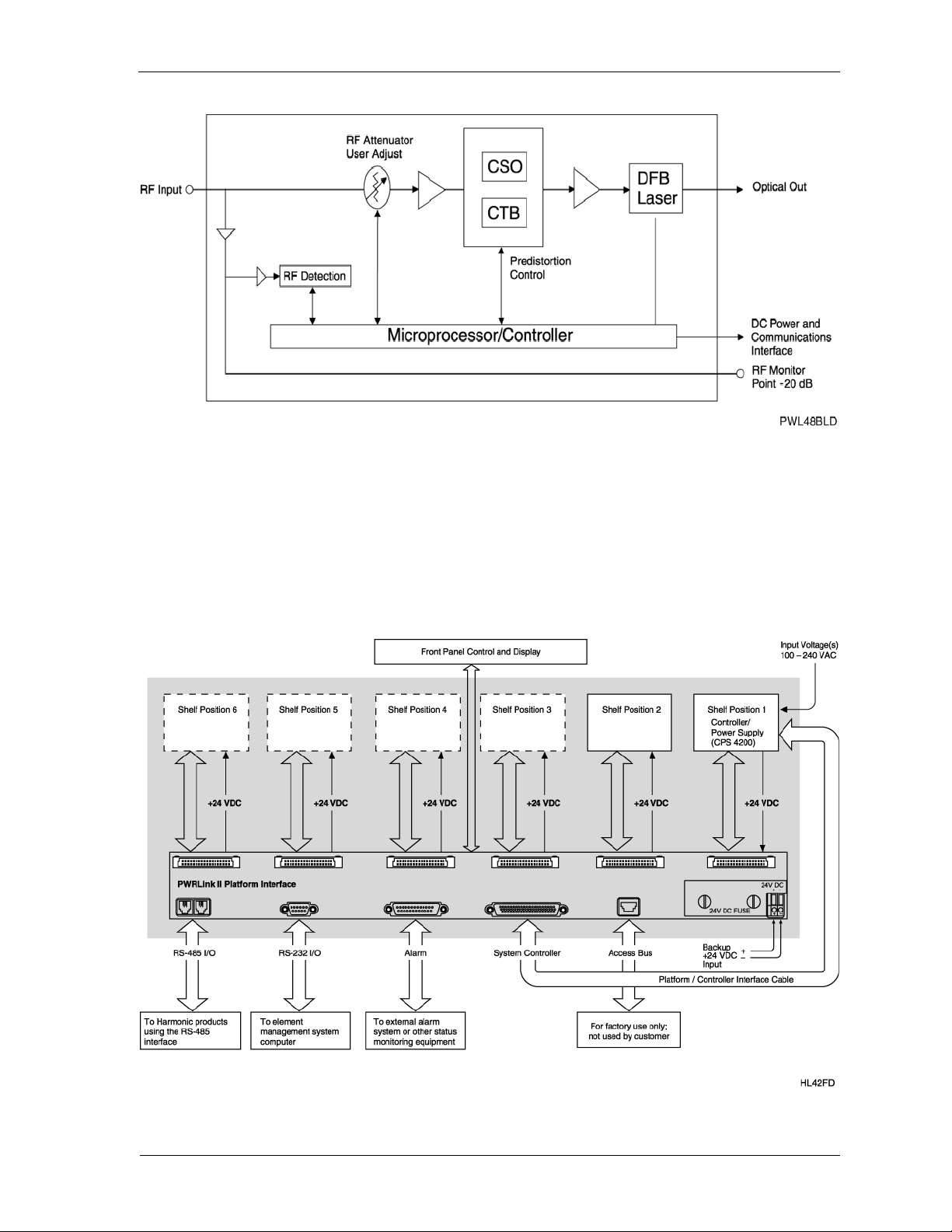
Figure 1-2. PWL 4800T block diagram
Description
The PWL 4800T transmitter is a compact plug-in module that mounts easily
in Harmonic’s HLP 4200 platform via the HMC 4000 module carrier. See
Figure 1-3 for a functional diagram of the HLP 4200 platform. The transmitter
module draws power from the platform’s 24 VDC power bus, and
communicates with the platform controller via the platform communication
bus.
Figure 1-3. HLP 4200 functional diagram
PWRLink II 4800T Optical Transmitter Product Manual Rev A (2/02) 1–3

Overview
For additional information on the HLP 4200 platform and its associated
communication and power buses, see the HLP 4200 Product Manual. For
further information on the platform controller and power supply options,
see the CPS 4200 or CPS 4248 manual.
1.3 Applications
The PWRLink II DFB transmitter is designed to operate alone or with other
systems, depending on the application:
• Alone, in local distribution and narrowcasting applications
• In combination with Harmonic’s MAXLink™ 1550 nm transmission
system, for complete broadband network solutions
The PWL 4800T provides an ultra-linear RF input-to-optical output (1310 nm)
response for the simultaneous transmission of analog video and digital
signals in the 45 to 870 MHz frequency band.
The 1310 nm optical signal transmitted by a PWRLink II module can be
received by optical receivers and nodes manufactured by Harmonic or other
major broadband equipment manufacturers. To learn more about equipment
compatibility and broadband network design and optimization, contact
customer service. See Appendix C, Harmonic Inc. – Offices .
1–4 Copyright © 2002 Harmonic Inc.

2
Installing the PWRLink II Transmitter
This chapter describes how to:
• Receive and inspect the PWRLink II transmitter
• Install the transmitter module in the HLP 4200 platform
• Connect the fiber cable
• Connect the RF broadband input
• Test RF signal input
2.1 Receiving and Inspecting
As you unpack your unit, inspect the shipping container and equipment for
damage. Save the shipping material for future use.
If the container or the equipment is damaged, notify both the freight carrier
and Harmonic. See Appendix C, Harmonic Inc. – Offices for contact
information.
CAUTION: Before removing equipment from its antistatic bag, touch a
ground point for several seconds. A suitable ground point is an
unpainted part of the chassis of a grounded piece of equipment.
2.2 Installing the Transmitter Module
CAUTION: To protect yourself from potential injury and to protect the
equipment from further damage, do not perform any
operational tests if the equipment appears to be damaged.
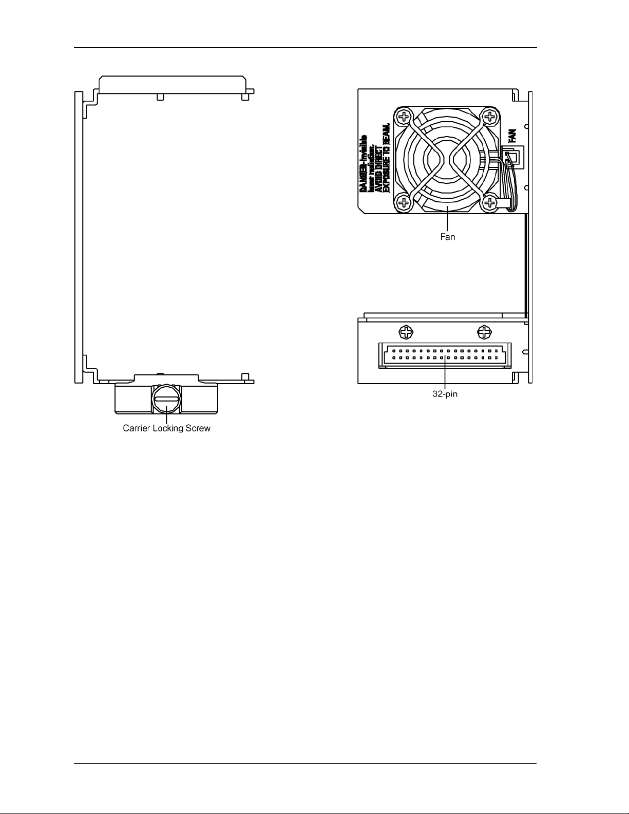
The PWRLink II transmitter module plugs into the HMC 4000 module carrier,
shown in Figure 2-1 on page 2-2. The transmitter module is held in the carrier
by a spring-loaded tab on the front handle of the carrier. You can place the
HMC 4000 carrier into any desired position in the HLP 4200 platform.
The PWRLink II module can be plugged into the carrier either with the carrier
already mounted in the HLP 4200 platform, or prior to mounting the carrier
into the platform. The HLP 4200 platform can be powered and operational
during the plug-in process.
PWRLink II 4800T Optical Transmitter Product Manual Rev A (2/02) 2–1
Installing the PWRLink II Transmitter
PL49CRR
Figure 2-1. HMC 4000 module carrier front and rear panel features
To install the transmitter module in the HMC 4000 carrier:
• Insert the transmitter into the carrier until it locks into position.
To remove the transmitter module from the HMC 4000 carrier:
• Press down the spring-loaded tab on the carrier, then pull out the module.
To install the HMC 4000 carrier in the HLP 4200 platform:
1. Lower the HLP 4200 platform’s control/display panel.
2. Slide the HMC 4000 carrier into any available slot in the platform until it is
properly seated.
3. Lock the carrier into position with the carrier locking screw, shown in
Figure 2-1.
The PWRLink II transmitter receives power from the HMC 4000 carrier.
The carrier is powered by the +24 VDC bus of the HLP 4200.
For additional information on the HLP 4200 platform, see the HLP 4200
Instruction Manual. For additional information on platform controllers and/or
power supply options, see the respective Harmonic manual for each
component .
2–2 Copyright © 2002 Harmonic Inc.

2.3 Connecting the Fiber Cable
The optical output connector of the PWRLink II transmitter is located on the
rear of the module, as shown in Figure 1-1 on page 1-2.
DANGER: Invisible Laser Radiation. AVOID EXPOSURE TO BEAM .
Never operate unit with a broken fiber or with a fiber connector
disconnected.
To connect fiber optic cable to the transmitter output:
1. Verify that the transmitter module has been mounted into the HLP 4200
platform, as described in Section 2.2.
2. Determine the connector type on the PWRLink II transmitter. The
standard optical connector recommended by Harmonic is SC/APC. Other
connector types can be special ordered.
3. Verify that the type of connector on the fiber cable is the same as what is
on the PWRLink II transmitter, for example the SC/APC.
4. Verify that the fiber cable connector has been cleaned properly. If the fiber
cable connector needs to be cleaned, follow the cleaning procedure
outlined in Section 5.1.1 Cleaning Patch Cord or Pigtail Fiber Optical
Connectors on page 5-2.
5. Verify that the PWRLink II optical connector has not been exposed to any
contamination. If you suspect that the connector may have been exposed
to contamination (for example, by a dirty fiber cable connector), follow the
cleaning procedure outlined in Section 5.1.2 Cleaning Transmitter Module
Optical Connectors on page 5-2.
Connecting the Fiber Cable
NOTE: Any contamination of either the fiber cable or PWRLink II
transmitter connector can significantly degrade optical link
performance. This degradation will most likely manifest itself
as poor carrier-to-noise (CNR) performance.
6. For SC-type optical connectors, note the key characteristics of the mating
connectors and align them accordingly. Gently insert the fiber cable
connector into that of the PWRLink II transmitter until the connector
clicks into place.
For FC-type optical connectors, note the key characteristics of the mating
connectors and align them accordingly. Gently insert the fiber cable
connector into that of the PWRLink II transmitter and tighten the rotating
sleeve of the connector. Do not overtighten!
2.4 Connecting the RF Broadband Input
The PWRLink II transmitter broadband RF connector is located on the rear
panel of the module, as shown in Figure 1-1 on page 1-2.
The PWRLink II female F connector accepts a 75 ohm impedance coaxial cable
terminated with a male F-type connector. The male F connector on the cable
should have a center pin diameter in the range of 0.64 mm to 0.8 mm. Insert
PWRLink II 4800T Optical Transmitter Product Manual Rev A (2/02) 2–3

Installing the PWRLink II Transmitter
the signal source connector into the PWRLink II module RF input connector
and tighten securely. The input video signal level must be between 16 dBmV
and 22 dBmV per analog video channel based on 76 PAL channels.
NOTE: To ensure performance integrity, use RG-59 coaxial cable. Use of a
connector with a center pin diameter greater than 0.8 mm can
damage the input RF connector.
2.5 Testing RF Signal Input
Once you have connected the RF signal source, you can use the RF monitor to
verify the presence of the RF signal input to the transmitter. The RF monitor is
a test connector (female F-type) located on the front panel of the transmitter
module, as shown in Figure 1-1 on page 1-2. The monitor level is 20 dB below
the input level to the transmitter ±1 dB.
2–4 Copyright © 2002 Harmonic Inc.

User Interface Options
This chapter describes:
• HLP 4200WD display
• NETWatch Site Controller
• Front panel RF adjustment
• Front panel LED indicators
3
Each PWRLink II transmitter module employs a microprocessor, which makes
it easy for you to communicate with and control the transmitter. This chapter
describes three options for such communication and control. The options are:
• HLP 4200WD push buttons and display
The HLP 4200WD interface provides the most comprehensive means
of monitoring and controlling PWRLink II transmitter performance.
The Autosetup and Reset to Factory Settings commands are available only
through this interface. For initial setup of the transmitter, Harmonic
recommends using the HLP 4200WD display, if available.
• NETWatch Site Controller Element Management System
Once installed and configured, NETWatch Site Controller provides a
straightforward way to monitor and control a network of multiple
PWRLink II transmitters, either locally or remotely.
• PWRLink II transmitter front panel RF adjustment
The RF adjustment potentiometer on the front panel of each PWRLink II
transmitter module (shown in Figure 1-1 on page 1-2 as RF Pad
Adjustment) can be used to set the internal RF pad level. Use this interface
only if the first two interface options are not available.
3.1 HLP 4200WD Display
The PWRLink II transmitter can be configured and monitored conveniently
via the push buttons and LCD display of the HLP 4200WD equipment
platform.
Figure 3-1 on page 3-2 provides a flowchart of the commands and messages in
the Main menu, which is at the top of the HLP 4200 WD platform interface
hierarchy. In this figure, push-button commands are framed in ovals, and
resultant display messages are framed in rectangular boxes.
PWRLink II 4800T Optical Transmitter Product Manual Rev A (2/02) 3–1
 Loading...