

Harmonic ProView PVR 6000 User Manual

ProView™ PVR 6000 Series
Professional Integrated Receiver Decoders
Version 4.1
Part Number: MAN-PVR6000-4.1
Revision A
© Harmonic Inc. 2006
ALL RIGHTS RESERVED

User Manual
© 2006 Harmonic Inc. All rights reserved.
Harmonic reserves the right to alter the equipment specifications and descriptions in
this publication without prior notice. No part of this publication shall be deemed to
be part of any contract or warranty unless specifically incorporated by reference into
such contract or warranty. The information contained herein is merely descriptive in
nature, and does not constitute a binding offer for sale of the product described
herein. Harmonic assumes no responsibility or liability arising from the use of the
products described herein, except as expressly agreed to in writing by Harmonic.
The use and purchase of this product does not convey a license under any patent
rights, copyrights, trademark rights, or any intellectual property rights of Harmonic.
Nothing hereunder constitutes a representation or warranty that using any products
in the manner described herein will not infringe any patents of third parties.
File ProView™ PVR 6000 User Rev 4.1

PVR 6000 Series
Professional Integrated Receiver Decoders
INTRODUCTION
Harmonic Inc. takes great pride in delivery of its products and makes every endeavor to
ensure its clients full satisfaction.
On behalf of the whole Harmonic team, we would like to extend our congratulations on
your investment in the ProView™ PVR 6000 series of Professional Integrated Receiver
Decoders.
MANUAL SCOPE AND STRUCTURE
The ProView™ PVR 6000 series Professional Integrated Receiver Decoders user manual is
comprised of the following main sections:
1. OVERVIEW:
This section provides the introduction and product description, including:
highlights, benefits and typical applications, a functional and physical
description of the unit, and its main capabilities and specifications.
2. INSTALLATION:
This section provides information and procedures required to install and
activate the unit. The procedures include: site preparation and requirements,
installation in a 19" rack, cable connections, rear panel options and pin-out
descriptions, initial settings, and serviceability check.
3. OPERATION:
This section provides information on the operation of the unit, as well as data
and instructions on using the unit and operating the control and monitoring
functions.
4. APPENDIXES
This section provides information on software loading and
downloading.
TECHNICAL SUPPORT
In case of technical problems with the IRD or one of its components, refer to the System
Documentation. Usually, this may assist you to resolve most technical difficulties.
Call your local distributor for technical support should you be unable to resolve the
problem.
Page i

User Manual
Overview
HOW TO RETURN FAULTY PARTS
Before Returning An Item:
• Request an RMA (Return Merchandise Authorization) Tracking Number from
your local distributor.
• Harmonic Support will assign an RMA Tracking Number; this must accompany
the item being returned and will be referred to in all correspondence.
• Send the item to Harmonic with the RMA Number included in the accompanying
documentation (shipping and customs forms).
Customer Support Contact Information
Harmonic Inc.
549 Baltic Way
Sunnyvale, California 94089
+1.408.542.2500
USA +1.800.788.1330
FAX +1.408.542.2510
http://www.harmonicinc.com
Email: support@harmonicinc.com
Page ii (Rev. 4.1/ SW v1.60/ December 2006)

PVR 6000 Series
Professional Integrated Receiver Decoders
Warranty
Harmonic warrants that the hardware (a tangible device or component thereof,
including any embedded code or firmware required for such device to function on
a stand-alone basis), purchased under Harmonic’s sales terms and conditions will
be free from defects of material and workmanship under normal use and service
as follows: (i) For a period of one (1) year following shipment by Harmonic,
Harmonic will supply, at no charge and at Harmonic’s option, either new or
refurbished replacement parts for defect parts of the products or new or
refurbished products to replace defective products; and (ii) For a period of one
(1) year following shipment by Harmonic, Harmonic will pay the labour charges
incurred by Harmonic to repair defective products. You are responsible for any
labour charges incurred following such one (1) year period.
This warranty will not apply to any products which have been repaired or altered
other than by Harmonic, your failure to meet environmental specifications, or
products which have been subjected to misuse, negligence, accident, unusual
physical or electrical stress, or other causes other than the normal and intended
use of the products.
THE WARRANTY FOR THE PRODUCTS AS SET FORTH HEREIN IS IN LIEU OF, AND
HARMONIC HEREBY DISCLAIMS, ALL OTHER WARRANTIES EXPRESSED,
STATUTORY OR IMPLIED, WHETHER ORAL OR WRITTEN, INCLUDING THE
IMPLIED WARRANTIES OF MERCHANTABILITY AND FITNESS FOR A PARTICULAR
PURPOSE.
COMPLIANCE EMC SAFETY
EN55022 (CISPR 22) EN60950
EN55024 (CISPR 24) CB (IEC60950)
EN55013 (CISPR 13) UL60950
EN55020 (CISPR 20) cTUVus
FCC part 15 (class B)
CB
Page iii

User Manual
Overview
CE Certification
The ProView™ PVR 6000 meets all the CE Class A requirements.
In order to meet CE requirements, appropriate cables must be connected on all ASI outputs (when
applicable). When cables are connected to these outputs then the device is compliant with the use of
FAIR-RITE 0443164151.
FCC Compliance Notice
Trade Name Harmonic
Product Name Integrated Receiver Decoder
Product Model Number ProView™ PVR 6000 Series
These devices comply with Part 15 of the FCC Rules.
OPERATION IS SUBJECT TO THE FOLLOWING TWO CONDITIONS:
These devices may not cause harmful interference.
These devices must accept any interference received, including interference that
may cause undesired operation.
The FCC Wants You to Know
This equipment has been tested and found to comply with the limits for a Class A
digital device, pursuant to Part 15 of the FCC rules. These limits are designed to
provide reasonable protection against harmful interference when the equipment is
operated in a commercial environment.
This equipment generates, uses and can radiate radio frequency energy and, if not
installed and used in accordance with the instructions, may cause harmful
interference to radio communications.
Operation of this equipment in a residential area is likely to cause harmful
interference, in which case the user will be required to correct the interference
at his expense.
FCC Warning
Modifications not expressly approved by the manufacturer could void the user
authority to operate the equipment under FCC Rules.
Page iv (Rev. 4.1/ SW v1.60/ December 2006)

PVR 6000 Series
Professional Integrated Receiver Decoders
WEEE/ROHS COMPLIANCE POLICY
Harmonic Inc. intends to fully comply with the European Union’s Directive
2002/96/EC as amended by Directive 2003/108/EC, on Waste Electrical
and Electronic Equipment, also known as “WEEE,” and Directive
2002/95/EC, as amended, on the Restriction of use of Hazardous
Substances, also known as “RoHS.”
Harmonic will ensure that product which cannot be re-used will be recycled
in compliance with the WEEE Directive. To that end, users are advised that
(1) Harmonic equipment is not to be discarded in household or office
garbage, (2) Harmonic Inc. will pay the freight for shipment of equipment
to be disposed of if it is returned to Harmonic, (3) customers should call
the normal RMA telephone numbers to arrange for such shipment, and (4)
customers may consult the Harmonic website
(
http://harmonicinc.com/ah_weee_recycle.cfm) for additional and updated
information on this process.
Harmonic will ensure that its products will either be re-used or recycled in
compliance with the WEEE Directive. For the latest information concerning
Harmonic’s WEEE/RoHS Compliance Policy and its Recycling and Take-Back
process, please visit our website.
Page v

User Manual
Overview
TABLE OF CONTENTS
Chapter 1. Overview........................................................1-1
1.1. General Information......................................................... 1-1
1.2. Highlights and Benefits..................................................... 1-2
1.3. Applications .................................................................... 1-3
1.4. Functionality ................................................................... 1-4
1.5. Mechanical Structure........................................................ 1-5
1.5.1. Front Panel ..................................................................... 1-5
1.5.2. Various Front-Ends .......................................................... 1-6
1.5.3. Software Permission (Licensing) ........................................ 1-7
1.5.4. PVR 6000 models ............................................................ 1-8
1.6. Management................................................................. 1-18
1.6.1. Local Management......................................................... 1-18
1.6.2. Remote Management ..................................................... 1-18
1.7. Characteristics and Specifications..................................... 1-19
1.7.1. Transport Stream Interface Options ................................. 1-19
1.7.2. Advanced Processing...................................................... 1-22
1.7.3. Decoder Outputs ........................................................... 1-23
1.7.4. Conditional Access ......................................................... 1-25
1.7.5. Control and Monitoring ................................................... 1-25
1.7.6. Compliance................................................................... 1-26
1.7.7. Environmental Conditions ............................................... 1-26
1.7.8. Physical and Power Specifications .................................... 1-27
Chapter 2. Installation .................................................... 2-1
2.1. Safety Precautions ........................................................... 2-1
2.2. Inventory Check.............................................................. 2-1
2.3. Installation Instructions.................................................... 2-2
2.3.1. Site Preparation .............................................................. 2-2
2.3.2. Mechanical Rack Installation.............................................. 2-2
2.3.3. Insertion of the DVB-CI Module (PCMCIA) ........................... 2-8
2.4. Cable Connection............................................................. 2-9
2.5. Initialization And Configuration........................................ 2-13
2.5.1. Electrical Power Connection............................................. 2-13
2.5.2. Powering Up ................................................................. 2-14
2.5.3. Tuning ......................................................................... 2-14
2.5.4. Performing Serviceability Check....................................... 2-15
Chapter 3. PVR 6000 Control Interfaces..........................3-1
3.1. Front Panel Control Interface............................................. 3-1
3.1.1. Controls and Displays....................................................... 3-1
3.1.2. PVR 6000 Front Panel Screen Types ................................... 3-2
3.1.3. PVR 6000 Menu Tree........................................................ 3-8
3.1.4. Front Panel Initialization Sequence..................................... 3-9
Page vi (Rev. 4.1/ SW v1.60/ December 2006)

PVR 6000 Series
Professional Integrated Receiver Decoders
3.2. Web Management Interface............................................. 3-10
Chapter 4. Operation and Management ...........................4-1
4.1. Preset Menu ....................................................................4-1
4.2. Configuration ..................................................................4-1
4.2.1. Receiver Modules .............................................................4-2
4.2.2. Satellite Receiver Modules................................................. 4-3
4.2.3. Stream Configuration Menu ............................................. 4-39
4.2.4. Filtering........................................................................ 4-46
4.2.5. Service Configuration Menu ............................................. 4-57
4.2.6. Video Configuration Menu................................................ 4-75
4.2.7. Audio Configuration Menu ............................................... 4-99
4.2.8. Data Configuration Menu............................................... 4-109
4.2.9. Conditional Access Configuration Menu............................ 4-120
4.2.10. Unit Configuration Menu................................................ 4-127
4.3. Status ........................................................................ 4-144
4.3.1. Receiver Status ........................................................... 4-145
4.3.2. Stream Status Menu..................................................... 4-152
4.3.3. Service Status ............................................................. 4-154
4.3.4. Video Status Menu ....................................................... 4-154
4.3.5. Audio Status Menu ....................................................... 4-158
4.3.6. Data Status Menu ........................................................ 4-160
4.3.7. Conditional Access Status Menu ..................................... 4-162
4.3.8. Unit Status Menu ......................................................... 4-165
APPENDIX
Appendix A Software Download ..........................................................A-1
Appendix B IP-Front End Software Upgrade Procedure ...........................B-1
Appendix C Aspect Ratio Configuration Process .....................................C-1
Appendix D Warning Messages .......................................................... D-1
Page vii

User Manual
Overview
LIST OF FIGURES
Figure 1-1: Signal Path in the PVR 6000 – Functionality Block Diagram...... 1-4
Figure 1-2: PVR 6000 Unit................................................................... 1-5
Figure 1-3: Front View of the IRD......................................................... 1-5
Figure 1-4: PVR 6010 Rear Panel (IP Input interface) .............................. 1-6
Figure 1-5: PVR 6010 Rear Panel (DVB-S Dual Input interface)................. 1-6
Figure 1-6: PVR 6010 Rear Panel (Decoder Only interface)....................... 1-7
Figure 1-7: PVR 6000 Rear Panel (Standard)......................................... 1-8
Figure 1-8: PVR 6010 Rear Panel.......................................................... 1-9
Figure 1-9: PVR 6020 Rear Panel........................................................1-10
Figure 1-10: PVR 6030 Rear Panel........................................................1-11
Figure 1-11: PVR 6040 Rear Panel........................................................1-12
Figure 1-12: PVR 6050 Rear Panel.........................................................1-13
Figure 1-13: PVR 6060 Rear Panel........................................................1-15
Figure 1-14: PVR 6070 Rear Panel........................................................1-16
Figure 1-15: PVR 6080 Rear Panel........................................................1-17
Figure 2-1: Pair of Rack Slides ............................................................. 2-3
Figure 2-2: Rack Slide Measurement Specifications ................................. 2-4
Figure 2-3: Laying the Device on the Rack-Slides ................................... 2-5
Figure 2-4: Clipped Mounting Brackets .................................................. 2-5
Figure 2-5: Device Mounted on a Pair of Rack-Slides............................... 2-6
Figure 2-6: Multiple Devices Mounted on a Single Pair of Rack-Slides......... 2-7
Figure 2-7: DVB-CI Module.................................................................. 2-8
Figure 2-8: PVR 6080 Rear Panel......................................................... 2-9
Figure 2-9: 9-Pin Male Connector Pin Numbering ...................................2-10
Figure 2-10: Power Supply Configurations and Rack-Mount Grounding Jackscrew
......................................................................................
Figure 3-1: Front Panel ....................................................................... 3-1
Figure 3-2: PVR 6000 Front Panel Menu (Root Menu) - Basic Structure ...... 3-8
Figure 3-3: PVR 6000 Web Management access box...............................3-10
Figure 3-4: PVR 6000 Web Management Interface Screen (Example)........3-11
Figure 4-1: PVR 6000 Configuration Main Menu ...................................... 4-2
Figure 4-2: DVB-S Receiver Parameters Menu Screen ............................. 4-4
Figure 4-3: DVB-S2 Receiver Parameters Menu Screen...........................4-12
Figure 4-4: DVB-DSNG Receiver Parameters Menu Screen ......................4-21
Figure 4-5: DVB-IP Receiver – MPEGoIP 1 Parameters Menu Screen.........4-29
Figure 4-6: DVB-IP Receiver – General Parameters Menu Screen .............4-35
Figure 4-7: Stream Configuration Menu................................................4-39
Figure 4-8: Stream Parameters Menu Screen ........................................4-40
Figure 4-9: General Filtering Parameters Menu Screen ...........................4-48
2-13
Page viii (Rev. 4.1/ SW v1.60/ December 2006)

PVR 6000 Series
Professional Integrated Receiver Decoders
Figure 4-10: Select Services Menu Screen ............................................. 4-52
Figure 4-11: Select PIDs Menu Screen .................................................. 4-55
Figure 4-12: Service Configuration Menu ............................................... 4-57
Figure 4-13: TV1 Menu Screen............................................................. 4-60
Figure 4-14: Preferred Language Screen................................................ 4-64
Figure 4-15: PID Select Menu Screen.................................................... 4-68
Figure 4-16: Port to Service Menu Screen.............................................. 4-71
Figure 4-17: General Service Menu Screen ............................................ 4-73
Figure 4-18: Video Configuration Menu.................................................. 4-75
Figure 4-19: Video 1 Menu Screen........................................................ 4-78
Figure 4-20: VBI 1 Parameters............................................................. 4-85
Figure 4-21: OSD1 Menu Screen .......................................................... 4-95
Figure 4-22: Audio Configuration Menu ................................................. 4-99
Figure 4-23: Audio 1 Menu Screen...................................................... 4-102
Figure 4-24: Data Configuration Menu................................................. 4-109
Figure 4-25: IP DATA PORT Menu Screen............................................. 4-114
Figure 4-26: Conditional Access Configuration Menu.............................. 4-120
Figure 4-27: Unit Configuration Menu.................................................. 4-127
Figure 4-28: Unit General Screen ....................................................... 4-130
Figure 4-29: Change Password Screen ................................................ 4-131
Figure 4-30: Unit Serial Screen .......................................................... 4-132
Figure 4-31: Unit Ethernet Screen ...................................................... 4-135
Figure 4-32: PVR 6000 Licensing Screen.............................................. 4-137
Figure 4-33: PVR 6000 Dry Contact Screen.......................................... 4-138
Figure 4-34: PVR 6000 Status Screen ................................................. 4-145
Figure 4-35: PVR 6000 DVBS Status Screen......................................... 4-146
Figure 4-36: PVR 6000 DVBS2 Status Screen....................................... 4-148
Figure 4-37: PVR 6000 DVB IP Status Screen....................................... 4-149
Figure 4-38: PVR 6000 Stream Status Screen ...................................... 4-152
Figure 4-39: PVR 6000 Service Status Screen ...................................... 4-154
Figure 4-40: PVR 6000 Video Status Screen......................................... 4-155
Figure 4-41: PVR 6000 Audio Status Screen......................................... 4-158
Figure 4-42: PVR 6000 IP Data Port Status Screen................................ 4-161
Figure 4-43: PVR 6000 Unit Status Screen........................................... 4-165
Figure 4-44: Unit – Identity (Status Screen) ........................................ 4-166
Figure 4-45: Unit – Versions (Status Screen) ....................................... 4-166
Figure A-1: Start Menu – Select Run .....................................................A-2
Figure A-2: Run Dialog Box.................................................................. A-3
Figure A-3: Open FTP Session ..............................................................A-3
Figure A-4: Login to FTP...................................................................... A-4
Figure A-5: Access Bin Folder ...............................................................A-4
Figure A-6: Loading the File .................................................................A-5
Figure A-7: Start Menu – Open HyperTerminal........................................ A-8
Page ix

User Manual
Overview
Figure A-8: HyperTerminal – Enter Connection ....................................... A-9
Figure A-9: Select PC COM Port............................................................ A-9
Figure A-10: Port Settings Tab ............................................................. A-10
Figure A-11: HyperTerminal Window..................................................... A-11
Figure A-12: Update Software Version Command ................................... A-12
Figure A-13: Erasing Flash Process ....................................................... A-13
Figure A-14: Ready to Receive New Software......................................... A-14
Figure A-15: Send File Dialog Box ........................................................ A-15
Figure A-16: Sending Status Dialog Box ................................................ A-15
Figure A-17: IRD Boot Application Starts ............................................... A-16
Figure A-18: Complete Software Loading............................................... A-17
Figure C-1: Aspect Ratio Conversion Machine ......................................... C-1
Figure C-2: Normal 4:3 Aspect Ratio..................................................... C-3
Figure C-3: Normal 16:9 Aspect Ratio ................................................... C-3
Figure D-1: Front panel warning LEDs ................................................... D-2
Page x (Rev. 4.1/ SW v1.60/ December 2006)

PVR 6000 Series
Professional Integrated Receiver Decoders
LIST OF TABLES
Table 2-1: PVR 6000 Rear Panel – Connectors and Cables....................... 2-9
Table 2-2: RS-232/RS-485 Control Connector Pin-Out .......................... 2-11
Table 2-3: RS-232 Low Speed Data and GPI Pin-Out ............................ 2-11
Table 2-4: RS-422 High Speed Data Pin-Out ....................................... 2-11
Table 2-5: Audio 3-4 Breakout Cable Pin-Out (Harmonic Inc. P/N 204346)2-12
Table 2-6: AES/EBU Balanced Breakout Cable Pin-Out (Harmonic Inc.
P/N 204345) .....................................................................
Table 2-7: PVR 6000 Serviceability Check .......................................... 2-15
Table 3-1: PVR 6000 Web Management Interface ................................ 3-11
Table 4-1: Band Frequency Range ....................................................... 4-5
Table 4-2: Band Frequency Designations ............................................ 4-13
Table 4-3: Band Frequency Range ..................................................... 4-22
Table C-1: Table of Conversions - 4:3 Stream Option .............................C-3
Table C-2: Table of Conversions - 16:9 Options .....................................C-5
Table A-1:
RS-232 Control Cable Pin-to-Pin........................................... A-6
Table A-2: RS-485 Control Cable Pin-to-Pin Designations ........................A-7
2-12
Page xi

PVR 6000 Series
Professional Integrated Receiver Decoders
Chapter 1.
OVERVIEW
1.1. GENERAL INFORMATION
The PVR 6000 professional MPEG-2 DVB and ATSC processing platform is
designed to meet even the most demanding application requirements while
maximizing ease of use and flexibility. With a graphical front-panel display, the
ProView™ PVR 6000 includes:
• Variety of Telco and cable front-end options
• MPEG-over-IP inputs
• MPEG-over-IP output
• ASI transport-stream input
• SNMP and web based management support
The ProView™ PVR 6000 concurrently decodes up to two video programs from
the transport stream.
The ProView™ PVR 6000 features the following product lines:
•
PVR 6000-6030: Professional single 4:2:0 decoder IRD
• PVR 6040-6050: Professional single 4:2:0/4:2:2 decoder IRD
• PVR 6060-6080: Professional dual 4:2:0 decoders PVR 6000
Housed in a true 1RU slim-line chassis and featuring low power consumption,
the PVR 6000 fully integrates with the Harmonic Inc. product platform.
Page 1-1

User Manual
1.2. HIGHLIGHTS AND BENEFITS
The processing platform’s main features and options include:
• Variety of front-end options including DVB-S, DVB-S2, DVB-DSNG, G.703,
MPEG-over-IP and DS3-ATM
• DVB-S2 professional
• MPEG-over-IP (MPEGoIP) inputs supporting up to 44Mbps (SPTS and MPTS)
• Configurable De-Jitter delay
• Physical Link Redundancy
• Logical Source Redundancy
• FEC (Forward Error Correction) ProMPEG CoP3v2
• MPEGoIP output supporting up to 60Mbps
• IP-over-MPEG output up to 60 Mbps (MPE decapsulation)
• 1 or 2 L-Band inputs
• ASI transport stream input and output
• Service and PID Filtering over the ASI and IP outputs (dynamic and static
modes)
• DVB common interface (2 slots – 1 active simultaneously)
• SDI, AES/EBU and analogue outputs
• Up to 4 pairs of audio outputs supporting:
Overview
• Musicam
• Dolby Digital
• Dolby Digital
• Linear PCM Audio and Dolby-E Pass-Through (up to 3 outputs)
• Embedded audio in SDI and re-insertion of VBI
• VBI re-insertion in composite and SDI
• Genlock for high-end accurate frame synchronization
• Redundancy support, 2 GPI Dry Contact relays with separate control
• OSD (On-Screen Display) subtitling
• Various of management interfaces: Graphical front-panel, user-friendly Web-
Interface, command-line-interface (CLI) and SNMP
• SW permission mechanism enables future upgrade
Page 1-2 (Rev. 4.1/ SW v1.60/ December 2006)
®
AC-3 Pass-Through
®
AC-3 2.0 Down Mixing

PVR 6000 Series
Professional Integrated Receiver Decoders
1.3. APPLICATIONS
The PVR 6000 processing platform is a technologically advanced choice for a
wide range of applications. Some typical uses for the include:
• Digital turnaround
• CATV IP head-end receiver/decoder
• CATV IP distribution edge decoder
• Satellite distribution
• Telco distribution
• DSNG
• Syndication
Harmonic Inc. offers this series of professional IRDs in a wide range of standard
configurations, with the flexibility to select specific interfaces and applicable
required features.
Page 1-3
User Manual
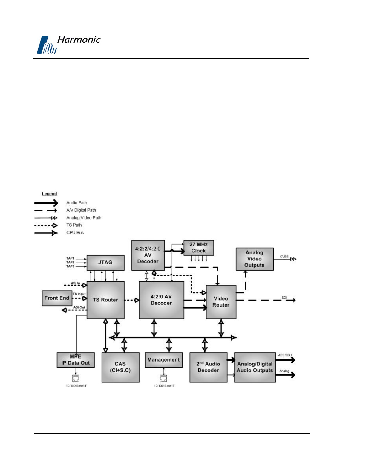
1.4. FUNCTIONALITY
The TS Router block receives input streams from an available source, for
example: L-Band, MPEG-over-IP IN and ASI IN. Then the block routes the
selected input to the Master and Slave decoders. Each decoder decodes one
program from the input stream, routed by the TS router block, and provides
decoded digital audio and video streams. These streams are provided to the
Video Router block that routes them to the relevant outputs as well as to the
analog video output. The Analog Video Output receives a digital video, converts
the digital video into analog video, and outputs the analog video. The analog
and digital audio output component outputs the digital and analog audio.
Overview
Figure 1-1: Signal Path in the PVR 6000 – Functionality Block Diagram
Page 1-4 (Rev. 4.1/ SW v1.60/ December 2006)

PVR 6000 Series
Professional Integrated Receiver Decoders
1.5. MECHANICAL STRUCTURE
The PVR 6000 is housed in a rugged industrial enclosure, 1RU by 19" (rack
mount).
Figure 1-2: PVR 6000 Unit
1.5.1. Front Panel
The front panel allows control using a four-way touch pad, [Enter] key, [Esc]
key, and two programmable [F1]/[F2] keys. Operational commands and
parameters are displayed on a graphical LCD. The four-way touch pad allows
parameter modification and scrolling through the embedded VBI menus. Two
LEDs show the WARNING and PWR/FAIL status (see
Figure 1-3: Front View of the IRD
Figure 1-3).
Page 1-5
User Manual
1.5.2. Various Front-Ends
PVR 6000 supports the following interfaces:
• DVB-S Single L-Band input
• DVB-S Dual L-Band input
• DVB-DSNG Dual L-Band input
• DVB-S2 Dual L-Band input
• MPEG over IP (MPEGoIP) dual input
• G.703 E3 single input with Loop-through
• ASI-In Decoder only (except for PVR 6000)
In this manual all rear panels are displayed with the DVB-S interface. Each
model has standard features and interfaces as well as features requiring active
software licenses.
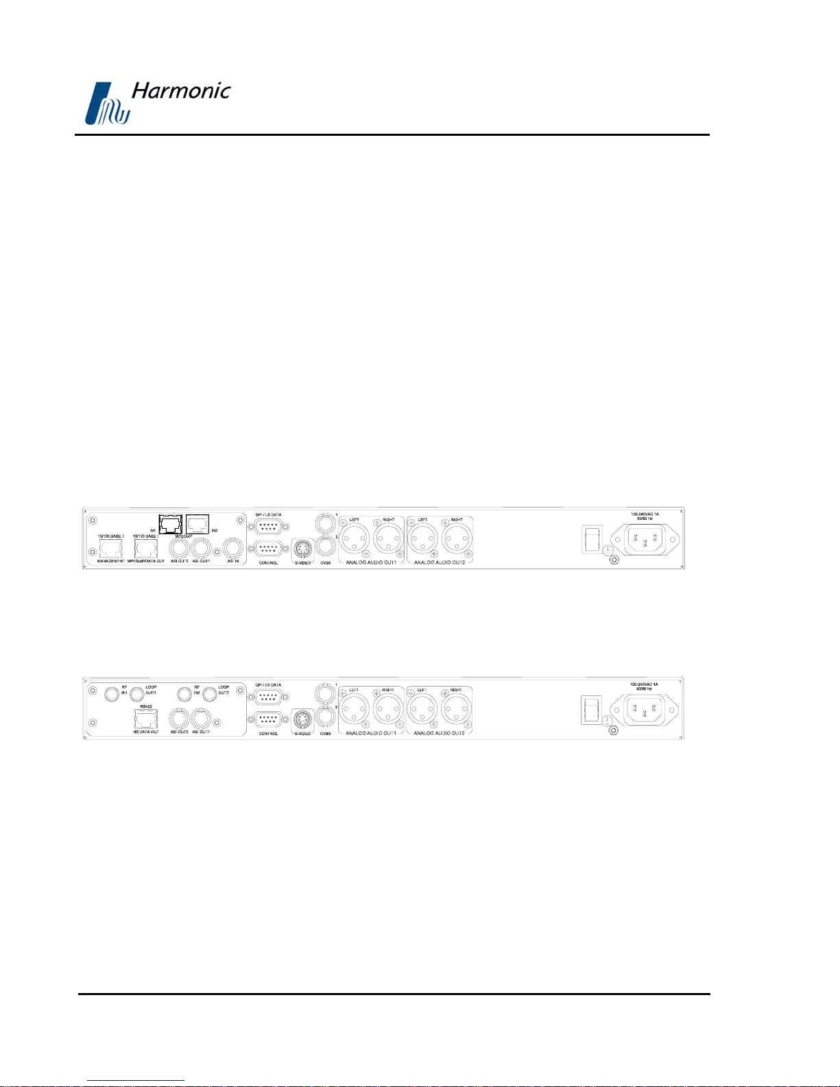
The MPEGoIP input interface can be supported by all PVR 6000 devices.
1-4 illustrates the PVR 6010 rear panel with an MPEGoIP input interface.
Overview
Figure
Figure 1-4: PVR 6010 Rear Panel (IP Input interface)
Figure 1-5 illustrates the PVR 6010 rear panel with DVB-S (QPSK) Dual Input
configuration.
Figure 1-5: PVR 6010 Rear Panel (DVB-S Dual Input interface)
Page 1-6 (Rev. 4.1/ SW v1.60/ December 2006)
PVR 6000 Series
Professional Integrated Receiver Decoders
Figure 1-6 displays the PVR 6010 rear panel with Decoder Only configuration.
Figure 1-6: PVR 6010 Rear Panel (Decoder Only interface)
NOTE
PVR 6000 models supporting MPEGoIP output and IP data out (MPE
de-capsulation) output can be configured to support either MPEGoIP or IP data
out.
1.5.3. Software Permission (Licensing)
Each PVR 6000 model is provided with a basic feature package. In order to suit
specific requirements, additional license-permitted features are available. The
Next chapter specifies the basic and optional features available for each model.
In order to enable optional features perform one of the following:
• Upon unit ordering - order the relevant features. The unit will be
provided with the ordered features enabled.
• After unit ordering - order the relevant features. In this case, a 16
character key issued by Harmonic Inc. will be provided. The key must
be entered to the unit thru the front-panel or the web-interface. For
details see section
4.2.10.5
NOTE
When RS-232 low-speed-data and/or RS-422 high-speed-data are enabled
the PID Filtering is unavailable.
Page 1-7
User Manual
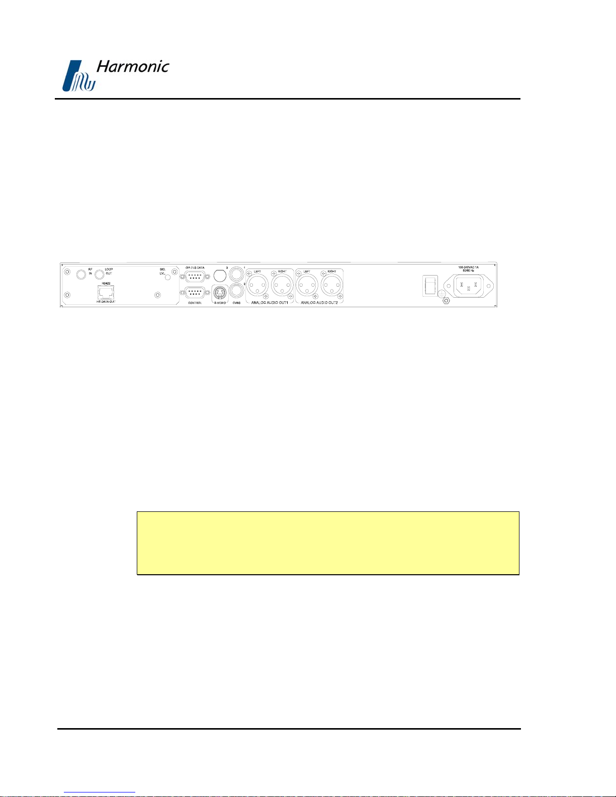
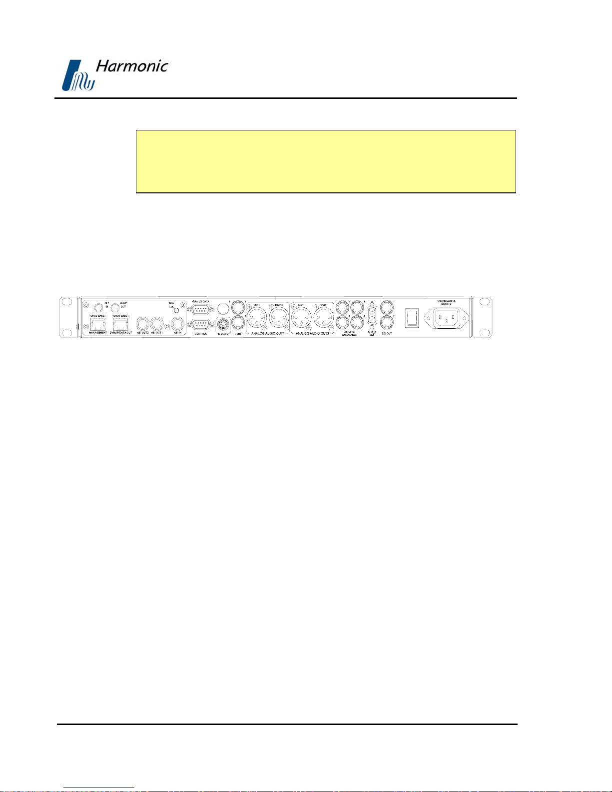
1.5.4. PVR 6000 models
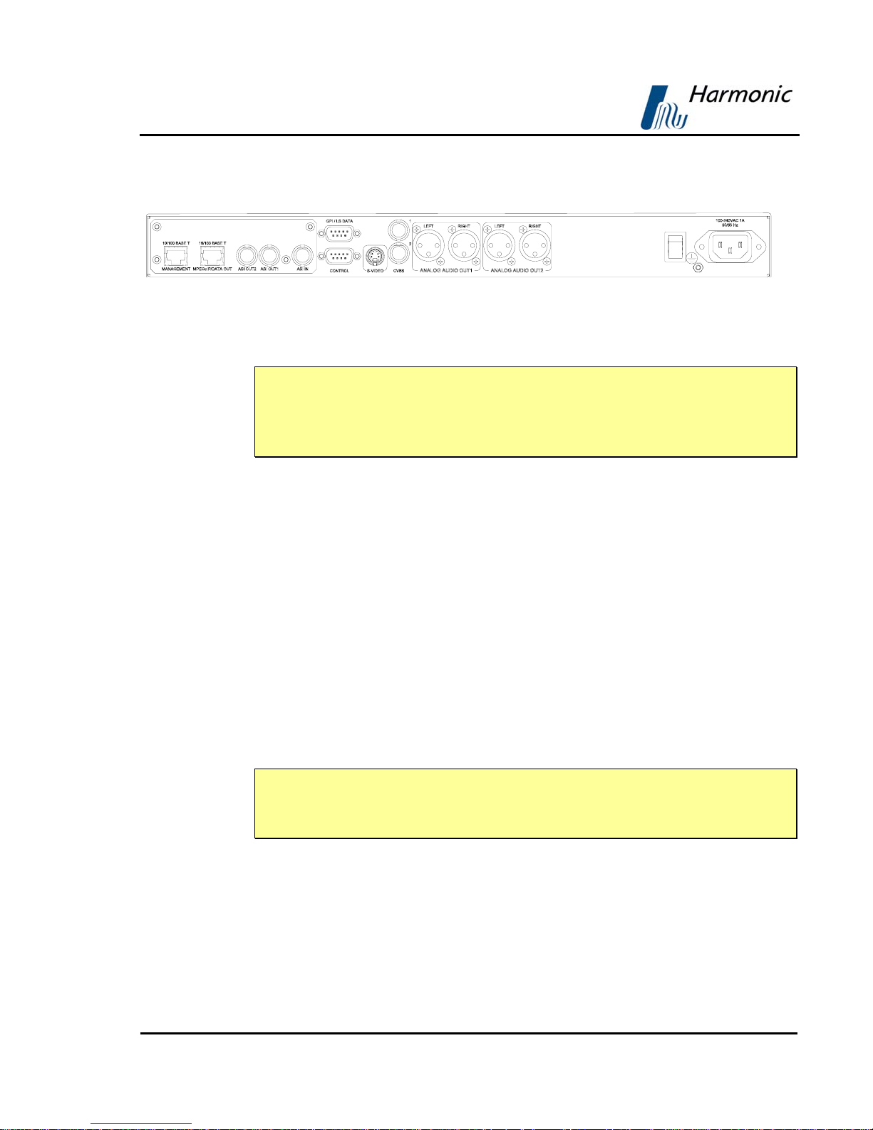
1.5.4.1. PVR 6000 Interfaces and Features
The PVR 6000 is a single 4:2:0 Decoder IRD. The PVR 6000 devices consist of
two composite video interfaces. The CVBS #1 connector is used for broadcasting
quality video and the CVBS #2 connector is used for monitoring.
Figure 1-7 illustrates the PVR 6000 rear panel. The PVR 6000 basic features and
software-licensed features are also detailed.
Figure 1-7: PVR 6000 Rear Panel (Standard)
Basic Features
• 1 composite video - Broadcast
quality (upper connector)
Software-Licensed Features
• Dolby digital (AC-3) LT/RT
downmixing
Overview
• 1 composite video - Monitoring
quality (lower connector)
• 2 active analog – audio - stereo
balanced interfaces
• GPI
• RS-232 low speed data output
• RS-422 high speed data output
NOTES
The PVR 6000 does not support the Decoder Only configuration.
The Russian SECAM D/K (composite video only) is available only through Special
orders.
Page 1-8 (Rev. 4.1/ SW v1.60/ December 2006)
PVR 6000 Series
Professional Integrated Receiver Decoders
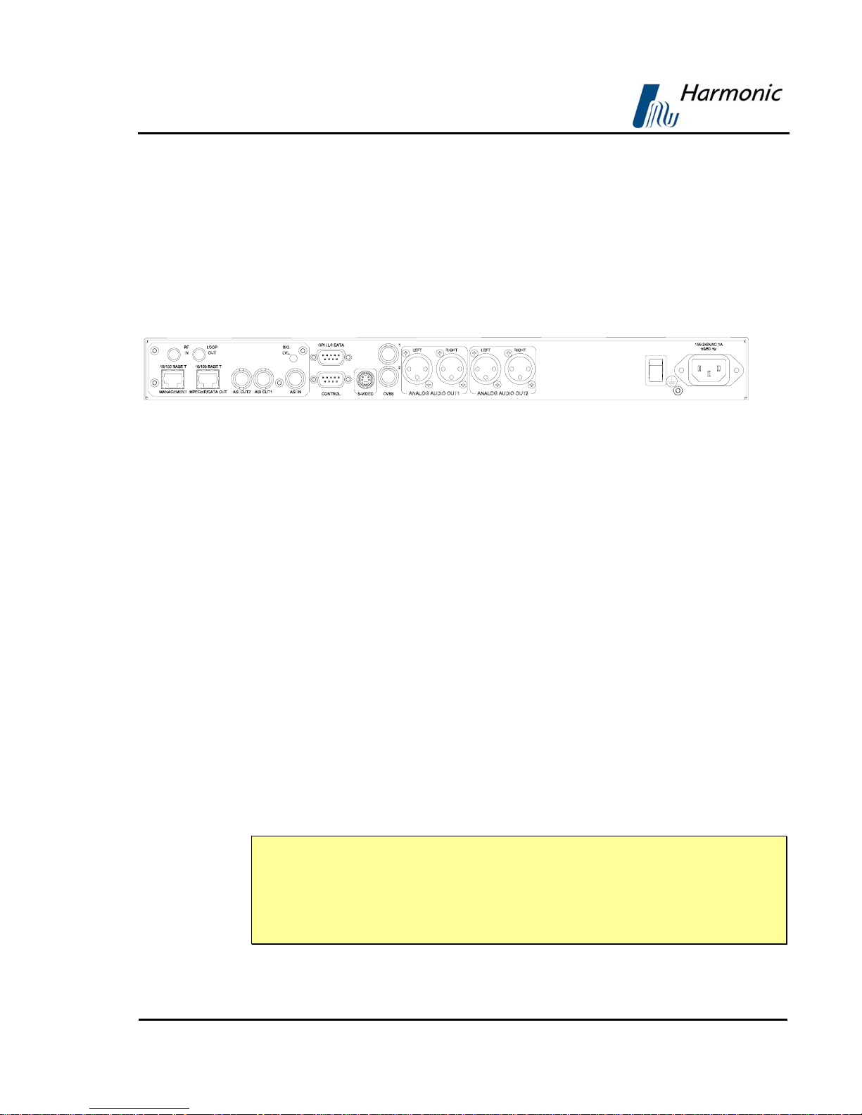
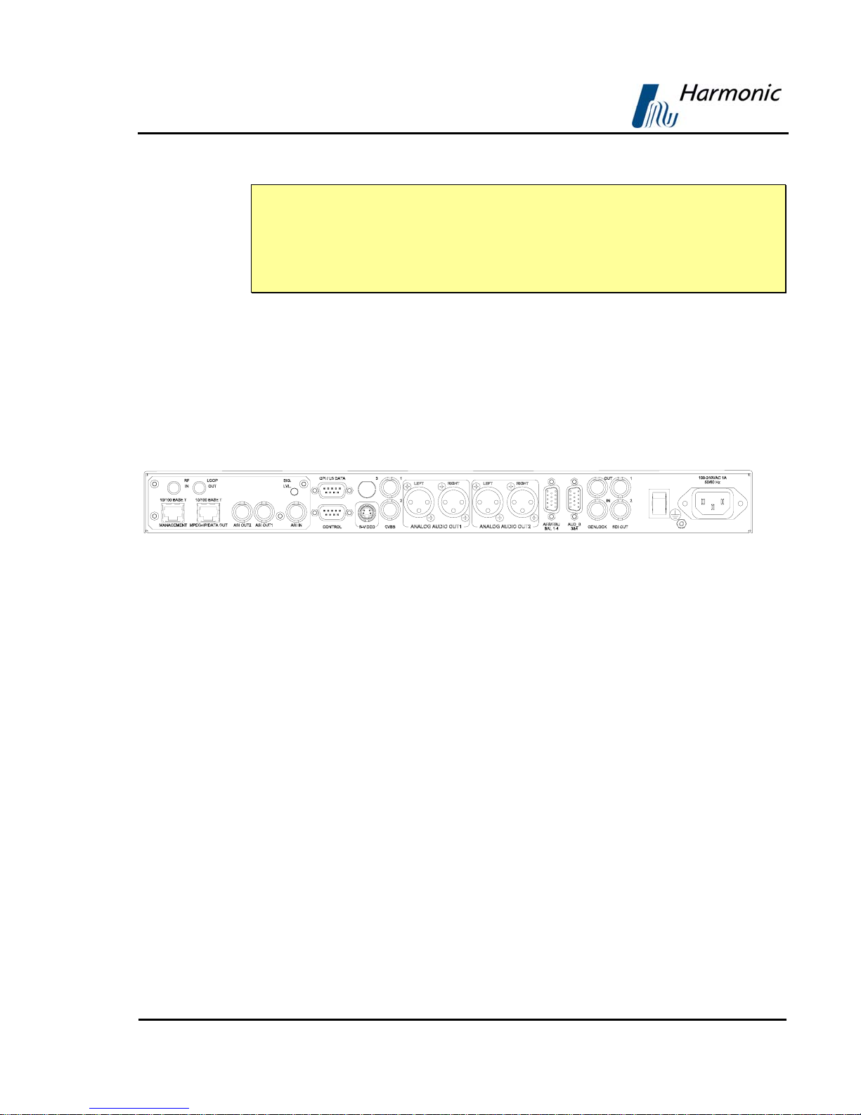
1.5.4.2. PVR 6010 Interfaces and Features
The PVR 6010 is a single 4:2:0 decoder IRD. The PVR 6010 family consists of
two composite video interfaces. The CVBS #1 connector is used for broadcast
quality video and the CVBS #2 connector is used for monitoring.
Figure 1-8 illustrates the PVR 6010rear panel. The PVR 6010basic features and
software-licensed features are also detailed.
Figure 1-8: PVR 6010Rear Panel
Basic Features
• 1 composite video - Broadcast
quality (upper connector)
• 1 composite video - Monitoring
quality (lower connector)
• 2 active analog – audio - stereo
balanced interfaces
• SNMP management (10/100 Base-T)
• Web based management
(10/100Base-T)
• GPI
NOTES
Software-Licensed Features
• ASI Input
• Dual (identical) ASI outputs
• MPEG-over-IP output or IP data
output (MPE de-capsulation)
• Dolby Digital (AC-3) LT/RT
downmixing
• Genlock input and loop-through
output
• Pro MPEG FEC
• IP Dual input (link and source
redundancy
• PID and service filtering
• RS-232 low speed data output
In the case of power failure or system shutdown, ASI OUT 1 output will become
ASI loop-through. Use ASI OUT 1 output for cascading a chain of PVR 6000.
The Russian SECAM D/K (composite video only) is available only through special
orders.
Page 1-9
User Manual
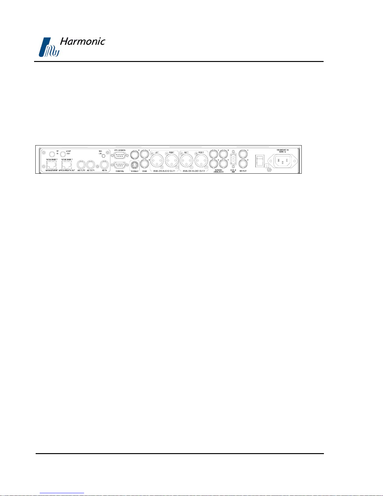
1.5.4.3. PVR 6020 Interfaces and Features
The PVR 6020 is a single 4:2:0 decoder. The entire PVR 6020 family consists of
two composite video interfaces. The CVBS #1 connector is used for broadcast
quality video and the CVBS #2 connector can is for monitoring.
Figure 1-9 illustrates the PVR 6020 rear panel. The PVR 6020 basic features and
software-licensed features are also detailed.
Figure 1-9: PVR 6020 Rear Panel
Basic Features
• 1 composite video - Broadcast
quality (upper connector)
• 1 composite video - Monitoring
quality (lower connector)
• 2 SDI interfaces
• Embedded VBI and up to 2 stereo
channels in SDI
• 2 activated analog-audio-stereo
balanced interfaces
• 2 activated AES/EBU-SPDIF audio-
unbalanced interfaces
• SNMP management (10/100 Base-T)
• Web-based management (10/100
Base-T)
Software-Licensed Features
• ASI Input
• Dual (identical) ASI outputs
• MPEG-over-IP output or IP data
output (MPE de-capsulation)
• Genlock input and loop-through
output
• Dolby Digital (AC-3) LT/RT
downmixing.
• Pro MPEG FEC
• PID and service filtering
• H.264 (One Program Only)
• RS-232 low speed data output
Overview
• GPI
• Front panel A/V monitoring
connectors
Page 1-10 (Rev. 4.1/ SW v1.60/ December 2006)
PVR 6000 Series
Professional Integrated Receiver Decoders
NOTE
In the case of power failure or system shutdown, ASI OUT 1 output will become
ASI loop-through. Use ASI OUT 1 output for cascading a chain of PVR 6000.
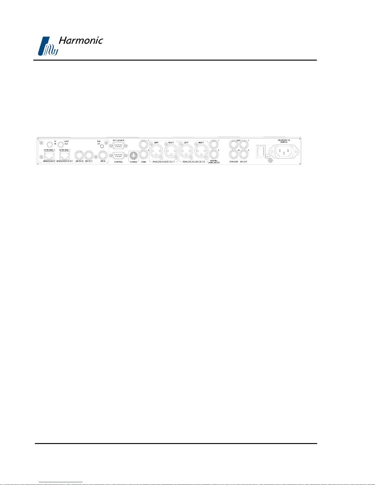
1.5.4.4. PVR 6030 Interfaces and Features
The PVR 6030 is a single 4:2:0 decoder. The entire PVR 6030 family consists of
two composite video interfaces. The CVBS #1 connector is used for broadcast
quality video and the CVBS #2 connector is used for monitoring.
Figure 1-10 illustrates the PVR 6030 rear panel. The PVR 6030 basic features
and software-licensed features are described below.
Figure 1-10: PVR 6030 Rear Panel
Basic Features
• 1 composite video - Broadcast
quality (upper connector)
• 1 composite video - Monitoring
quality (lower connector)
• 2 SDI interfaces
• Embedded VBI and up to 2 stereo
channels in SDI
• 2 active analog-audio-stereo
balanced interfaces
• 2 active AES/EBU-SPDIF audio-
balanced interfaces
• SNMP management (10/100 Base-T)
• Web-based management (10/100
Base-T)
• GPI
• Front panel A/V monitoring
connectors
Software-Licensed Features
• ASI input
• Dual (identical) ASI output
• MPEG-over-IP output or IP data
output (MPE de-capsulation)
• Genlock input and loop-through
output
• Dolby Digital (AC-3) LT/RT
downmixing
• Pro MPEG FEC
• IP Dual input (link and source
redundancy
• PID and service filtering
• RS-232 low speed data output
Page 1-11
User Manual
NOTES
This model requires a breakout cable to connect to the AES/EBU interfaces.
In case of power failure or system shutdown, ASI OUT 1 output will become ASI
loop-through. Use ASI OUT 1 output for cascading a chain of PVR 6000
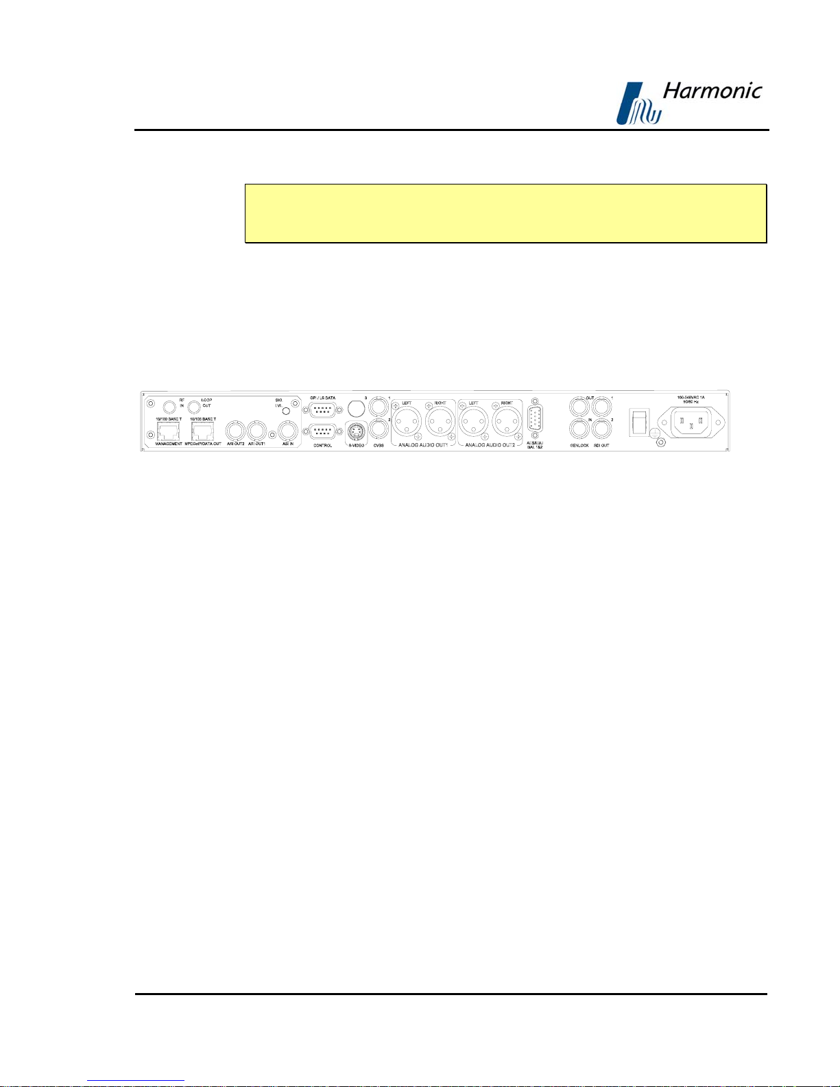
1.5.4.5. PVR 6040 Interfaces and Features
The PVR 6040 is a single 4:2:0/4:2:2 decoder. The PVR-6040 family consists
of two composite video interfaces. Both CVBS #1 and CVBS #2 connectors are
for broadcast quality video.
Figure 1-11 illustrates the PVR 6040 rear panel. The PVR 6040 basic and
software-licensed features are also detailed.
Figure 1-11: PVR 6040 Rear Panel
Basic Features
Software-Licensed Features
Overview
• 2 composite video interfaces –
Broadcast quality
• 2 SDI interfaces
• Embedded VBI and up to 4 stereo
channels in SDI
• Decoding 4:2:2 PP@ML (1.5–50 Mbps)
• 2 out of 4 active analog-audio-stereo
balanced interfaces
• 2 out of 4 active AES/EBU-SPDIF audio
unbalanced interfaces
ST
• 1
• SNMP management (10/100 Base-T)
• Web-based management (10/100
• GPI
• Front panel A/V monitoring connectors
and 2ND active AES/EBU-SPDIF
Base-T)
• ASI input
• Dual (identical) ASI output
• MPEG-over-IP output or IP data output (MPE
de-capsulation)
• 3RD Active analog stereo pair
• 4TH Active analog stereo pair
RD
• 3
• 4
• Dolby Digital (AC-3) LT/RT downmixing
• Linear PCM (SMPTE 302M 2000), Dolby-E
• Pro MPEG FEC
• IP Dual input (link and source redundancy
• PID and service filtering
• RS-232 low speed data output
Active AES/EBU-SPDIF
TH
Active AES/EBU-SPDIF
pass-through
Page 1-12 (Rev. 4.1/ SW v1.60/ December 2006)
PVR 6000 Series
Professional Integrated Receiver Decoders
NOTES
This model requires a breakout cable to connect to the 3rd and 4th analog stereo
pairs.
In the case of power failure or system shutdown, ASI OUT 1 output will become
ASI loop-through. Use ASI OUT 1 output for cascading a chain of PVR 6000.
1.5.4.6. PVR 6050 Interfaces and Features
The PVR 6050 is a single 4:2:2 decoder. The PVR-6050 family consists of two
composite video interfaces. Both CVBS interfaces are for service broadcast video
quality.
Figure 1-12 illustrates the PVR 6050 rear panel. The PVR 6050 basic and
software-licensed features are also detailed.
Figure 1-12: PVR 6050 Rear Panel
Basic Features
• 2 composite video interfaces – Broadcast
quality
• 2 SDI interfaces
• Embedded VBI and up to 4 stereo
channels in SDI
• Decoding 4:2:2 PP@ML (1.5–50 Mbps)
• 2 out of 4 active analog-audio-stereo
balanced interfaces
• 2 out of 4 active AES/EBU-SPDIF audio-
balanced interfaces
• Genlock input and loop-through output
• SNMP management (10/100 Base-T)
Software-Licensed Features
• ASI input
• Dual (identical) ASI output
• MPEG-over-IP output or IP data
output (MPE de-capsulation)
rd
Active analog stereo pair
• 3
• 4th Active analog stereo pair
rd
• 3
Active AES/EBU-SPDIF
th
Active AES/EBU-SPDIF
• 4
• Dolby Digital (AC-3) LT/RT
downmixing
• Linear PCM (SMPTE 302M 2000),
Dolby-E pass-through
Page 1-13

User Manual
• Web-based management (10/100
Base-T)
• GPI
• Front panel A/V monitoring connectors
• Genlock input and loop-through
output
• Dolby Digital (AC-3) LT/RT
downmixing.
• Pro MPEG FEC
• PID and service filtering
• H.264 (One Program Only)
• RS-232 low speed data output
Overview
NOTES
This model requires a breakout cable to connect to the AES/EBU interfaces and
to connect to the 3rd and 4th analog stereo pairs.
In the case of power failure or system shutdown, ASI OUT 1 output will become
ASI loop-through. Use ASI OUT 1 output for cascading a chain of PVR 6000.
Page 1-14 (Rev. 4.1/ SW v1.60/ December 2006)
PVR 6000 Series
Professional Integrated Receiver Decoders
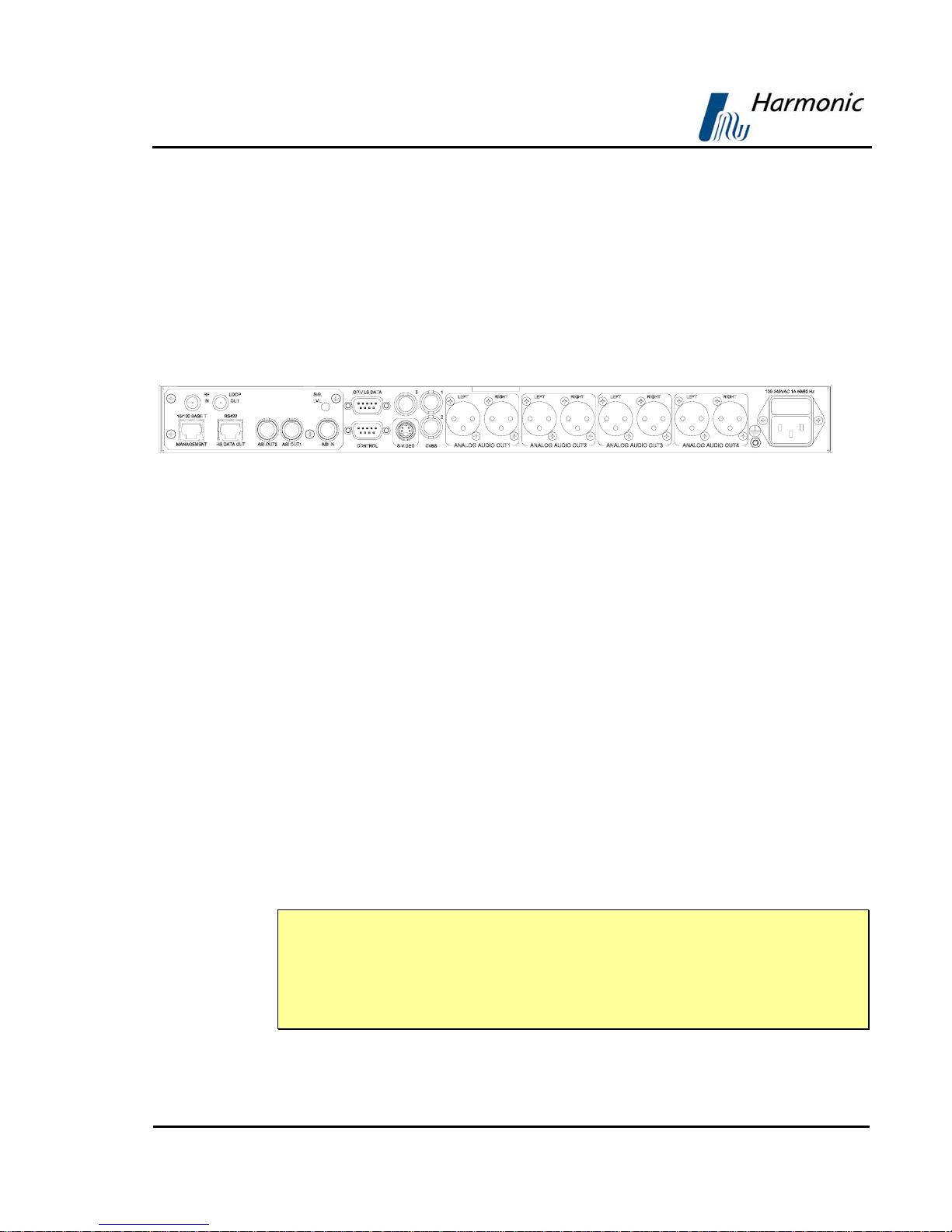
1.5.4.7. PVR 6060 Interfaces and Features
The PVR 6060 is a dual 4:2:0 decoder. The PVR-6060 family consists of three
composite video interfaces. The CVBS #1 connector is for the broadcast quality
video of decoder #1. The CVBS #2 is used for monitoring. The CVBS #3
connector is for the broadcast quality video of decoder #2.
Figure 1-13 illustrates the PVR 6060 rear panel. The PVR 6060 basic and
software-licensed features are also detailed.
Figure 1-13: PVR 6060 Rear Panel
Basic Features
• 1 composite video for program 1- Broadcast
quality (upper-right connector)
• 1 composite video for program 2 -
Broadcast quality (upper-left connector)
• 1 composite video for program 1-
Monitoring quality (lower connector)
• 4 active analog-audio-stereo balanced
interfaces
• SNMP management (10/100 Base-T)
• Web-based management (10/100 Base-T)
• RS-422 high speed data output
• GPI
NOTE
In the case of power failure or system shutdown, ASI OUT 1 output will become
ASI loop-through. Use ASI OUT 1 output for cascading a chain of PVR 6000.
The Russian SECAM D/K (composite video only) is available only through special
orders.
Software Licensed Features
• ASI input
• Dual (identical) ASI output
• Dolby Digital (AC-3) LT/RT
downmixing
• H.264 (One program only)
• RS-232 low speed data output
• RS-422 high speed data output
Page 1-15
User Manual
1.5.4.8. PVR 6070 Interfaces and Features
The PVR 6070 is a dual 4:2:0 decoder. The PVR-6070 family consists of three
composite video interfaces. The CVBS #1 connector is for the broadcast quality
video of decoder #1. The CVBS #2 is used for monitoring. The CVBS #3
connector is for broadcast quality video of decoder #2.
Figure 1-13 illustrates the PVR 6070 rear panel. The PVR 6070 basic features
and software-licensed features are also detailed.
Figure 1-14: PVR 6070 Rear Panel
Basic Features
• 3 composite video interfaces (2 for
broadcast, 1 for monitoring)
• 2 SDI interfaces
• Embedded VBI and up to 4 stereo
channels in SDI
• 4 active analog-audio-stereo
balanced interfaces
• 4 active AES/EBU-SPD IF audi o
unbalanced interface
• SNMP management (10/100
Base-T)
• Web-based management (10/100
Base-T)
Software-Licensed Features
• ASI input
• Dual (identical) ASI output
• MPEG-over-IP output or IP data
output (MPE de-capsulation)
• Dolby Digital (AC-3) LT/RT
downmixing
• Linear PCM (SMPTE 302M 2000),
Dolby-E pass-through.
• Pro MPEG FEC
• H.264 (One program only)
• PID and service filtering
• RS-232 low speed data output
Overview
• GPI
Page 1-16 (Rev. 4.1/ SW v1.60/ December 2006)
 Loading...