

Harmonic ProView 7000, ProView 7100 User Manual

ProView 7000/7100™
Multifunctional Receiver
User Guide
VERSION 2.6
Rev. E
Manual Part No. MAN-PVR-7K-2.6

Disclaimer
Harmonic reserves the right to alter the equipment specifications and descriptions in this publication without prior notice. No part of
this publication shall be deemed to be part of any contract or warranty unless specifically incorporated by reference into such
contract or warranty. The information contained herein is merely descriptive in nature, and does not constitute a binding offer for
sale of the product described herein. Harmonic assumes no responsibility or liability arising from the use of the products described
herein, except as expressly agreed to in writing by Harmonic. The use and purchase of this product do not convey a license under
any patent rights, copyrights, trademark rights, or any intellectual property rights of Harmonic. Nothing hereunder constitutes a
representation or warranty that using any products in the manner described herein will not infringe any patents of third parties.
Trademark Acknowledgments
Harmonic and all Harmonic product names are trademarks of Harmonic Inc. All other trademarks are the property of their respective
owners.
Compliance and Approval
This equipment generates, uses, and can radiate radio frequency energy. It may cause harmful interference to radio communications
if it is not installed and used in accordance with the instructions in this manual. Operation of this equipment in a residential area is
likely to cause harmful interference. If this occurs, the user will be required to correct the interference at his or her own expense.
This equipment has been tested and found to comply with the limits for a Class A digital device, pursuant to Part 15, Subpart B of the
Federal Communications Commission (FCC) rules.
These limits are designed to provide reasonable protection against harmful interference when the equipment is operated in a
commercial environment.
This device complies with Part 15 of the FCC rules. Operation is subject to the following two conditions: (1) this device may not
cause harmful interference, and (2) this device must accept any interference received, including interference that may cause
undesired operation.
Connections between the Harmonic equipment and other equipment must be made in a manner that is consistent with maintaining
compliance with FCC radio frequency emission limits. Modifications to this equipment not expressly approved by Harmonic may
void the authority granted to the user by the FCC to operate this equipment.
WEEE/RoHS Compliance Policy
Harmonic Inc. intends to comply fully with the European Union’s Directive 2002/96/EC as amended, on Waste Electrical and
Electronic Equipment, also known as “WEEE,” and Directive 2002/95/EC, as amended, on the Restriction of use of Hazardous
Substances, also known as “RoHS.”
Harmonic will ensure that product which cannot be reused will be recycled in compliance with the WEEE Directive. To that end,
users are advised that (1) Harmonic equipment is not to be discarded in household or office garbage, (2) Harmonic Inc. will pay the
freight for shipment of equipment to be disposed of if it is returned to Harmonic, (3) customers should call the normal RMA
telephone numbers to arrange for such shipment, and (4) for additional and updated information on this process customers may
consult the Harmonic website: http://harmonicinc.com/pa_weee_recycle.cfm.
Harmonic will ensure that its products will be either reused or recycled in compliance with the WEEE Directive. For the latest
information concerning Harmonic’s WEEE/RoHS Compliance Policy and its Recycling and Take-Back process, please visit our web
site.
© 2012 Harmonic Inc. All rights reserved.

产品中的有毒有害物质或元素的名称及含量表
Names and Contents of the Toxic and Hazardous Substances or Elements in the
Products if the Part is Present
该表显示哈雷公司产品中可能含有的有毒有害物质元配件的信息,除了来源于元配件供应商的物料成分资料,
亦来自其它相关的机构与资料。哈雷产品不一定使用这些元配件。
This table shows those components where hazardous substances may be found in Harmonic products based on, among other
things, material content information provided by third party suppliers. These components may or may not be part of the product.
除非特殊注明,哈雷公司产品的环保使用期限 均为 20 年。该环保使用期限的有效条件为:必须遵循该产品使
用手册的规定,对该产品进行使用或存储。
The Environmental Protective Use Period for Harmonic products is 20 years unless displayed otherwise on the product. The EPUP
period is valid only when the products are operated or stored as per the conditions specified in the product manual.
有毒有害物质或元素 (Hazardous Substance)
部件名称 (Part name)
铅
(PB) 汞(Hg)镉(Cd)
六价铬
(CrVI)
多溴联苯
(PBB)
多溴二苯醚
(PBDE)
印刷线路板
(Printed Circuit Assemblies)
机械组件
(Mechanical Subassemblies)
光学组件
(Optical Subassemblies)
电源
(Power Supplies)
缆线 / 线束
(Cables, harnesses)
屏幕 / 显示器
(Screens, Monitors)
金属零件
(Metal Parts)
塑
料 / 发泡材料
(Plastics, foams)
电池
(Batteries)
XOO O O O
XOO O O O
XOO O O O
XOO O O O
XOO O O O
XOO O O O
OOO O O O
OOO O O O
XOO O O O
O: 表示在该部件的所有均质材料中,此类有毒有害物质的含量均小于 SJ/T11363-2006 标准所规定的限量。
O: Indicates the content of the toxic and hazardous substances at the homogeneous material level of the parts is below the limit
defined in SJ/T11363 2006 standard.
X: 表示至少在该部件的某一均质材料中,此类有毒有害物质的含量超出 SJ/T11363-2006 标准规定的限量。
X: Indicates that the content of the toxic and hazardous substances in at least one of the homogeneous materials of the parts is
above the limit defined in SJ/T11363 2006 standard.
© 2012 Harmonic Inc. All rights reserved.
Korean Compliance
Standards and Agency Approval
The following tables list regulatory standards and agency approvals:
North America
Standards Agency Approval
EMI: FCC Part 15, Subpart B, ICES-003, Issue 2, Class A FCC
Safety: UL 60950-1, CSA 60950-1 cTUV-us Mark
Europe
EMI/EMC: EN55022, Class A, EN55024 CE
Safety: EN 60950-1, EN60825-1 TUV-GS or T-Mark, CE
Japan
EMI: VCCI V-3 2009 VCCI
Australia and New Zealand
EMI: AS/NZS CISPR22:2006 N/A
Korea
Standards Agency Approval
Standards Agency Approval
Standards Agency Approval
Standards Agency Approval
EMC: KN22 and KN 24 KCC
© 2012 Harmonic Inc. All rights reserved.
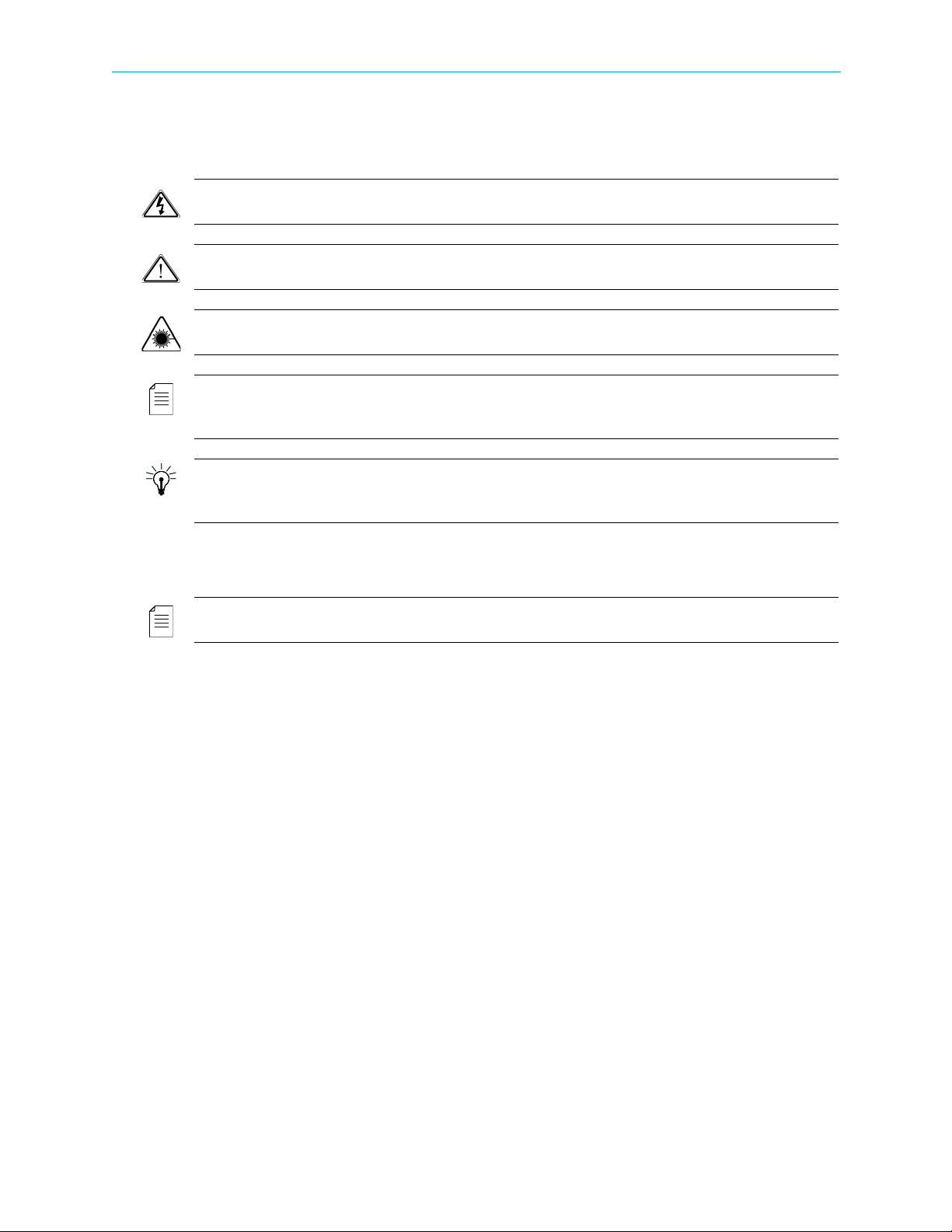
Documentation Conventions
This manual uses some special symbols and fonts to call your attention to important information. The
following symbols appear throughout this manual:
DANGER: The Danger symbol calls your attention to information that, if ignored, can cause physical harm
to you.
CAUTION: The Caution symbol calls your attention to information that, if ignored, can adversely affect
the performance of your Harmonic product, or that can make a procedure needlessly difficult.
LASER DANGER: The Laser symbol and the Danger alert call your attention to information about the
lasers in this product that, if ignored, can cause physical harm to you.
NOTE: The Note symbol calls your attention to additional information that you will benefit from heeding.
It may be used to call attention to an especially important piece of information you need, or it may provide
additional information that applies in only some carefully delineated circumstances.
TIP: The Tip symbol calls your attention to parenthetical information that is not necessary for performing
a given procedure, but which, if followed, might make the procedure or its subsequent steps easier,
smoother, or more efficient.
NOTE: You require Adobe Reader or Adobe Acrobat version 6.0 or later to open the PDF files. You can
download Adobe Reader free of charge from www.adobe.com.
© 2012 Harmonic Inc. All rights reserved.

Table of Contents
Table of Contents
Chapter 1 Introduction
1.1 General Information . . . . . . . . . . . . . . . . . . . . . . . . . . . . . . . . . . . . . . . . . . . . . . . . . 11
1.2 Main ProView 7000™/7100 Applications . . . . . . . . . . . . . . . . . . . . . . . . . . . . . . . . 12
1.2.1 TS Descrambling Applications . . . . . . . . . . . . . . . . . . . . . . . . . . . . . . . . . . . . . . . . . 12
1.2.2 Decoding Applications . . . . . . . . . . . . . . . . . . . . . . . . . . . . . . . . . . . . . . . . . . . . . . . 12
1.3 ProView 7000™ Platform Main Features and Configurations . . . . . . . . . . . . . . . . 12
1.3.1 Multi-Transport Stream Descrambler . . . . . . . . . . . . . . . . . . . . . . . . . . . . . . . . . . . 13
1.3.2 Multi-Format Decoder . . . . . . . . . . . . . . . . . . . . . . . . . . . . . . . . . . . . . . . . . . . . . . . 14
1.3.3 DMS (Distribution Management System) . . . . . . . . . . . . . . . . . . . . . . . . . . . . . . . . 16
1.4 ProView 7000™ Mechanical Structure. . . . . . . . . . . . . . . . . . . . . . . . . . . . . . . . . . . 17
1.4.1 ProView 7000™ Enclosure. . . . . . . . . . . . . . . . . . . . . . . . . . . . . . . . . . . . . . . . . . . . . 17
1.4.2 ProView 7000™/7100 Front Panel . . . . . . . . . . . . . . . . . . . . . . . . . . . . . . . . . . . . . . 17
1.4.3 ProView 7000™ Rear Panel. . . . . . . . . . . . . . . . . . . . . . . . . . . . . . . . . . . . . . . . . . . . 17
1.5 ProView 7000™ Management. . . . . . . . . . . . . . . . . . . . . . . . . . . . . . . . . . . . . . . . . . 18
Chapter 2 Quick Start
2.1 Installation and Cable Connection. . . . . . . . . . . . . . . . . . . . . . . . . . . . . . . . . . . . . . 19
2.1.1 Installation. . . . . . . . . . . . . . . . . . . . . . . . . . . . . . . . . . . . . . . . . . . . . . . . . . . . . . . . . 19
2.1.2 Electrical connection. . . . . . . . . . . . . . . . . . . . . . . . . . . . . . . . . . . . . . . . . . . . . . . . . 19
2.1.3 Cable Connections. . . . . . . . . . . . . . . . . . . . . . . . . . . . . . . . . . . . . . . . . . . . . . . . . . . 20
2.2 Switching On . . . . . . . . . . . . . . . . . . . . . . . . . . . . . . . . . . . . . . . . . . . . . . . . . . . . . . .20
2.3 Configuring the IP Parameters . . . . . . . . . . . . . . . . . . . . . . . . . . . . . . . . . . . . . . . . . 20
2.4 Configuring and Monitoring. . . . . . . . . . . . . . . . . . . . . . . . . . . . . . . . . . . . . . . . . . . 21
2.4.1 A Typical ProView 7000™ Configuration Using the Front Panel . . . . . . . . . . . . . . 21
2.4.2 EMS Initial Setup. . . . . . . . . . . . . . . . . . . . . . . . . . . . . . . . . . . . . . . . . . . . . . . . . . . . 25
2.4.3 A Typical ProView 7000™ Configuration Using EMS . . . . . . . . . . . . . . . . . . . . . . . 27
Chapter 3 Front Panel Overview
3.1 Main Elements and Structure. . . . . . . . . . . . . . . . . . . . . . . . . . . . . . . . . . . . . . . . . . 32
3.2 Front Panel Display . . . . . . . . . . . . . . . . . . . . . . . . . . . . . . . . . . . . . . . . . . . . . . . . . . 33
3.2.1 Menu Pages . . . . . . . . . . . . . . . . . . . . . . . . . . . . . . . . . . . . . . . . . . . . . . . . . . . . . . . . 34
3.2.2 Parameter Pages . . . . . . . . . . . . . . . . . . . . . . . . . . . . . . . . . . . . . . . . . . . . . . . . . . . . 34
3.2.3 Edit Value Pages . . . . . . . . . . . . . . . . . . . . . . . . . . . . . . . . . . . . . . . . . . . . . . . . . . . . 35
3.2.4 Radio Select Pages . . . . . . . . . . . . . . . . . . . . . . . . . . . . . . . . . . . . . . . . . . . . . . . . . . 35
Chapter 4 Device Configuring Using the Front Panel
4.1 Configuring the DVB-S/S2 Input Port Properties . . . . . . . . . . . . . . . . . . . . . . . . . . 36
4.2 Configuring the Decoding. . . . . . . . . . . . . . . . . . . . . . . . . . . . . . . . . . . . . . . . . . . . . 39
4.2.1 Service Selection Mode. . . . . . . . . . . . . . . . . . . . . . . . . . . . . . . . . . . . . . . . . . . . . . . 40
4.2.2 Video Configuration . . . . . . . . . . . . . . . . . . . . . . . . . . . . . . . . . . . . . . . . . . . . . . . . . 41
4.2.3 PCR Configuration. . . . . . . . . . . . . . . . . . . . . . . . . . . . . . . . . . . . . . . . . . . . . . . . . . . 43
4.2.4 Audio 1 / 2 Configuration. . . . . . . . . . . . . . . . . . . . . . . . . . . . . . . . . . . . . . . . . . . . . 44
4.2.5 VBI/VANC Configuration. . . . . . . . . . . . . . . . . . . . . . . . . . . . . . . . . . . . . . . . . . . . . . 45
© 2012 Harmonic Inc. 6 ProView 7000 v.2.6, Rev. E

Table of Contents
4.2.6 DPI to GPI. . . . . . . . . . . . . . . . . . . . . . . . . . . . . . . . . . . . . . . . . . . . . . . . . . . . . . . . . .46
4.3 Routing and Descrambling . . . . . . . . . . . . . . . . . . . . . . . . . . . . . . . . . . . . . . . . . . . . 46
4.4 Configuring the GbE Ports, Sockets and Routing Table . . . . . . . . . . . . . . . . . . . . . 50
4.5 CA Definitions . . . . . . . . . . . . . . . . . . . . . . . . . . . . . . . . . . . . . . . . . . . . . . . . . . . . . . 53
4.5.1 BISS . . . . . . . . . . . . . . . . . . . . . . . . . . . . . . . . . . . . . . . . . . . . . . . . . . . . . . . . . . . . . . 53
4.5.2 CAM 1/2 Sub Menu. . . . . . . . . . . . . . . . . . . . . . . . . . . . . . . . . . . . . . . . . . . . . . . . . . 53
4.5.3 CAM Association . . . . . . . . . . . . . . . . . . . . . . . . . . . . . . . . . . . . . . . . . . . . . . . . . . . . 53
4.5.4 Selecting All Elementary Streams . . . . . . . . . . . . . . . . . . . . . . . . . . . . . . . . . . . . . . 53
4.5.5 Configuring Only Relevant Elementary Streams. . . . . . . . . . . . . . . . . . . . . . . . . . . 54
4.5.6 Accessing the CAM MMI Menu . . . . . . . . . . . . . . . . . . . . . . . . . . . . . . . . . . . . . . . . 54
4.6 Unit Menu . . . . . . . . . . . . . . . . . . . . . . . . . . . . . . . . . . . . . . . . . . . . . . . . . . . . . . . . . 54
4.6.1 Management Port Menu. . . . . . . . . . . . . . . . . . . . . . . . . . . . . . . . . . . . . . . . . . . . . . 54
4.6.2 SW Version Menu . . . . . . . . . . . . . . . . . . . . . . . . . . . . . . . . . . . . . . . . . . . . . . . . . . . 55
4.6.3 HW Inventory Menu . . . . . . . . . . . . . . . . . . . . . . . . . . . . . . . . . . . . . . . . . . . . . . . . . 55
4.6.4 Date/Time Menu . . . . . . . . . . . . . . . . . . . . . . . . . . . . . . . . . . . . . . . . . . . . . . . . . . . . 56
4.6.5 Set Active Version . . . . . . . . . . . . . . . . . . . . . . . . . . . . . . . . . . . . . . . . . . . . . . . . . . . 56
4.6.6 License . . . . . . . . . . . . . . . . . . . . . . . . . . . . . . . . . . . . . . . . . . . . . . . . . . . . . . . . . . . . 56
4.6.7 BOOTP Menu . . . . . . . . . . . . . . . . . . . . . . . . . . . . . . . . . . . . . . . . . . . . . . . . . . . . . . . 56
4.6.8 LCD Contrast Menu . . . . . . . . . . . . . . . . . . . . . . . . . . . . . . . . . . . . . . . . . . . . . . . . . . 56
4.6.9 GPI Menu. . . . . . . . . . . . . . . . . . . . . . . . . . . . . . . . . . . . . . . . . . . . . . . . . . 56
4.6.10 Reset Unit Menu . . . . . . . . . . . . . . . . . . . . . . . . . . . . . . . . . . . . . . . . . . . . . . . . . . . . 56
4.6.11 Restore to Defaults Menu. . . . . . . . . . . . . . . . . . . . . . . . . . . . . . . . . . . . . . . . . . . . . 57
4.7 Presets . . . . . . . . . . . . . . . . . . . . . . . . . . . . . . . . . . . . . . . . . . . . . . . . . . . . . . . . . . . . 57
Chapter 5 Monitoring Using the Front Panel
5.1 Device Monitoring. . . . . . . . . . . . . . . . . . . . . . . . . . . . . . . . . . . . . . . . . . . . . . . . . . . 58
5.1.1 Status OK . . . . . . . . . . . . . . . . . . . . . . . . . . . . . . . . . . . . . . . . . . . . . . . . . . . . . . . . . .58
5.1.2 Alarms . . . . . . . . . . . . . . . . . . . . . . . . . . . . . . . . . . . . . . . . . . . . . . . . . . . . . . . . . . . . 59
5.2 Monitoring the DVB-S/S2 Input Port Properties. . . . . . . . . . . . . . . . . . . . . . . . . . . 61
5.3 Monitoring the Decoding . . . . . . . . . . . . . . . . . . . . . . . . . . . . . . . . . . . . . . . . . . . . . 62
Chapter 6 Remote Management using EMS
6.1 Configuring the IP Parameters . . . . . . . . . . . . . . . . . . . . . . . . . . . . . . . . . . . . . . . . . 63
6.2 EMS System Requirements . . . . . . . . . . . . . . . . . . . . . . . . . . . . . . . . . . . . . . . . . . . . 64
6.3 Installing EMS . . . . . . . . . . . . . . . . . . . . . . . . . . . . . . . . . . . . . . . . . . . . . . . . . . . . . . 64
6.4 Launching EMS . . . . . . . . . . . . . . . . . . . . . . . . . . . . . . . . . . . . . . . . . . . . . . . . . . . . . 65
6.5 Adding a Device. . . . . . . . . . . . . . . . . . . . . . . . . . . . . . . . . . . . . . . . . . . . . . . . . . . . . 65
6.6 Changing a Device’s Connection Settings . . . . . . . . . . . . . . . . . . . . . . . . . . . . . . . . 66
6.7 Connecting a Device . . . . . . . . . . . . . . . . . . . . . . . . . . . . . . . . . . . . . . . . . . . . . . . . . 67
6.8 Checking Device Connectivity . . . . . . . . . . . . . . . . . . . . . . . . . . . . . . . . . . . . . . . . . 67
6.9 Disconnecting a Device. . . . . . . . . . . . . . . . . . . . . . . . . . . . . . . . . . . . . . . . . . . . . . . 68
6.10 Removing a Device . . . . . . . . . . . . . . . . . . . . . . . . . . . . . . . . . . . . . . . . . . . . . . . . . . 69
6.11 Displaying the Device Explorer. . . . . . . . . . . . . . . . . . . . . . . . . . . . . . . . . . . . . . . . . 69
6.12 EMS GUI Structure . . . . . . . . . . . . . . . . . . . . . . . . . . . . . . . . . . . . . . . . . . . . . . . . . . 69
6.13 Manipulating EMS GUI Components . . . . . . . . . . . . . . . . . . . . . . . . . . . . . . . . . . . . 70
6.14 Refreshing the EMS Screen . . . . . . . . . . . . . . . . . . . . . . . . . . . . . . . . . . . . . . . . . . . 70
6.14.1 EMS Device Explorer . . . . . . . . . . . . . . . . . . . . . . . . . . . . . . . . . . . . . . . . . . . . . . . . . 72
© 2012 Harmonic Inc. 7 ProView 7000 v.2.6, Rev. E

Table of Contents
Chapter 7 Device Configuring Using EMS
7.1 Physical Input Ports and Slots . . . . . . . . . . . . . . . . . . . . . . . . . . . . . . . . . . . . . . . . . 74
7.1.1 ASI Input Port Properties . . . . . . . . . . . . . . . . . . . . . . . . . . . . . . . . . . . . . . . . . . . . . 75
7.1.2 DVB-S/S2 Input Port Properties . . . . . . . . . . . . . . . . . . . . . . . . . . . . . . . . . . . . . . . . 75
7.1.3 GbE Ports for Input . . . . . . . . . . . . . . . . . . . . . . . . . . . . . . . . . . . . . . . . . . . . . . . . . . 80
7.1.4 CAM Slots. . . . . . . . . . . . . . . . . . . . . . . . . . . . . . . . . . . . . . . . . . . . . . . . . . . . . . . . . .85
7.1.5 CAM Properties . . . . . . . . . . . . . . . . . . . . . . . . . . . . . . . . . . . . . . . . . . . . . . . . . . . . . 87
7.1.6 BISS Table Management . . . . . . . . . . . . . . . . . . . . . . . . . . . . . . . . . . . . . . . . . . . . . . 88
7.2 Multiplex Inputs . . . . . . . . . . . . . . . . . . . . . . . . . . . . . . . . . . . . . . . . . . . . . . . . . . . . 89
7.2.1 Input Programs Management. . . . . . . . . . . . . . . . . . . . . . . . . . . . . . . . . . . . . . . . . . 90
7.2.2 Input Tables Management . . . . . . . . . . . . . . . . . . . . . . . . . . . . . . . . . . . . . . . . . . . . 91
7.2.3 Input Unreferenced PIDs Management . . . . . . . . . . . . . . . . . . . . . . . . . . . . . . . . . . 92
7.2.4 Multiplex In Port Properties . . . . . . . . . . . . . . . . . . . . . . . . . . . . . . . . . . . . . . . . . . . 92
7.2.5 Input Program Properties . . . . . . . . . . . . . . . . . . . . . . . . . . . . . . . . . . . . . . . . . . . . . 95
7.2.6 Input Elementary Stream Properties . . . . . . . . . . . . . . . . . . . . . . . . . . . . . . . . . . . . 96
7.2.7 Input Conditional Access Messages Properties. . . . . . . . . . . . . . . . . . . . . . . . . . . . 96
7.2.8 Input Tables Properties . . . . . . . . . . . . . . . . . . . . . . . . . . . . . . . . . . . . . . . . . . . . . . . 97
7.2.9 Input Unreferenced PID Properties. . . . . . . . . . . . . . . . . . . . . . . . . . . . . . . . . . . . . . 98
7.3 Multiplex & Decoding Outputs. . . . . . . . . . . . . . . . . . . . . . . . . . . . . . . . . . . . . . . . . 98
7.3.1 Multiplex Output. . . . . . . . . . . . . . . . . . . . . . . . . . . . . . . . . . . . . . . . . . . . . . . . . . . . 99
7.3.2 Multiplex Output Properties. . . . . . . . . . . . . . . . . . . . . . . . . . . . . . . . . . . . . . . . . .105
7.3.3 Transport Stream Port Route Properties dialog. . . . . . . . . . . . . . . . . . . . . . . . . . . 106
7.3.4 Output Multiplex Program Properties . . . . . . . . . . . . . . . . . . . . . . . . . . . . . . . . . . 107
7.3.5 Output Multiplex Elementary Stream Properties . . . . . . . . . . . . . . . . . . . . . . . . .108
7.3.6 Output Tables Properties. . . . . . . . . . . . . . . . . . . . . . . . . . . . . . . . . . . . . . . . . . . . . 109
7.3.7 Output Unreferenced PID Properties . . . . . . . . . . . . . . . . . . . . . . . . . . . . . . . . . . . 111
7.3.8 Decoding Channel Properties . . . . . . . . . . . . . . . . . . . . . . . . . . . . . . . . . . . . . . . . .112
7.4 Physical Outputs . . . . . . . . . . . . . . . . . . . . . . . . . . . . . . . . . . . . . . . . . . . . . . . . . . .123
7.4.1 ASI Output Port Properties . . . . . . . . . . . . . . . . . . . . . . . . . . . . . . . . . . . . . . . . . . .124
7.4.2 GbE Ports for Output. . . . . . . . . . . . . . . . . . . . . . . . . . . . . . . . . . . . . . . . . . . . . . . . 125
7.5 Element Properties . . . . . . . . . . . . . . . . . . . . . . . . . . . . . . . . . . . . . . . . . . . . . . . . . 128
7.6 Cross Connections . . . . . . . . . . . . . . . . . . . . . . . . . . . . . . . . . . . . . . . . . . . . . . . . . . 129
7.6.1 Setting Multiplex Cross Connections. . . . . . . . . . . . . . . . . . . . . . . . . . . . . . . . . . . 129
7.6.2 Input to Decoder Channel Connection . . . . . . . . . . . . . . . . . . . . . . . . . . . . . . . . . 137
7.6.3 Editing and Deleting . . . . . . . . . . . . . . . . . . . . . . . . . . . . . . . . . . . . . . . . . . . . . . . . 138
7.7 CAM Slot Management. . . . . . . . . . . . . . . . . . . . . . . . . . . . . . . . . . . . . . . . . . . . . . 138
7.7.1 Descrambling a Cross Connected Program . . . . . . . . . . . . . . . . . . . . . . . . . . . . . . 139
7.7.2 Descrambling a Decoded Program . . . . . . . . . . . . . . . . . . . . . . . . . . . . . . . . . . . . . 140
7.8 EMS Connection Wizard . . . . . . . . . . . . . . . . . . . . . . . . . . . . . . . . . . . . . . . . . . . . . 140
7.8.1 Setting Program Cross-Connection using the Connection Wizard . . . . . . . . . . .141
7.8.2 Setting Decoding Channel using the Connection Wizard . . . . . . . . . . . . . . . . . . 142
7.9 Low Delay Mode . . . . . . . . . . . . . . . . . . . . . . . . . . . . . . . . . . . . . . . . . . . . . . . . . . . 143
7.9.1 Selecting Low Delay Mode . . . . . . . . . . . . . . . . . . . . . . . . . . . . . . . . . . . . . . . . . . .144
7.10 Device Management . . . . . . . . . . . . . . . . . . . . . . . . . . . . . . . . . . . . . . . . . . . . . . . .145
7.10.1 HDMI and DVI Output . . . . . . . . . . . . . . . . . . . . . . . . . . . . . . . . . . . . . . . . . . . . . . . 146
7.10.2 Reboot Device . . . . . . . . . . . . . . . . . . . . . . . . . . . . . . . . . . . . . . . . . . . . . . . . . . . . . 146
7.10.3 Device Identification . . . . . . . . . . . . . . . . . . . . . . . . . . . . . . . . . . . . . . . . . . . . . . . . 146
© 2012 Harmonic Inc. 8 ProView 7000 v.2.6, Rev. E

Table of Contents
7.10.4 Reset CAM Slot . . . . . . . . . . . . . . . . . . . . . . . . . . . . . . . . . . . . . . . . . . . . . . . . . . . . 146
7.10.5 Log-In / Log-Out Control of the Device. . . . . . . . . . . . . . . . . . . . . . . . . . . . . . . . . 147
7.10.6 Setting Up/Changing the Device Log-in Password . . . . . . . . . . . . . . . . . . . . . . . . 147
7.10.7 Managing Presets . . . . . . . . . . . . . . . . . . . . . . . . . . . . . . . . . . . . . . . . . . . . . . . . . . 147
7.10.8 Backing Up/Restoring the Device Configuration. . . . . . . . . . . . . . . . . . . . . . . . . . 150
7.10.9 Restoring the Factory/Default Device Access Passwords . . . . . . . . . . . . . . . . . . .152
7.11 Device Properties. . . . . . . . . . . . . . . . . . . . . . . . . . . . . . . . . . . . . . . . . . . . . . . . . . . 153
7.11.1 Network Properties . . . . . . . . . . . . . . . . . . . . . . . . . . . . . . . . . . . . . . . . . . . . . . . . . 153
7.11.2 Hardware Properties . . . . . . . . . . . . . . . . . . . . . . . . . . . . . . . . . . . . . . . . . . . . . . . . 155
7.11.3 Device Communication Properties . . . . . . . . . . . . . . . . . . . . . . . . . . . . . . . . . . . . . 160
7.11.4 Device Users’ Access Properties . . . . . . . . . . . . . . . . . . . . . . . . . . . . . . . . . . . . . . . 162
7.11.5 Device Software Upgrade Properties . . . . . . . . . . . . . . . . . . . . . . . . . . . . . . . . . . .163
7.11.6 Device License Properties . . . . . . . . . . . . . . . . . . . . . . . . . . . . . . . . . . . . . . . . . . . . 164
7.11.7 Device Date and Time Properties . . . . . . . . . . . . . . . . . . . . . . . . . . . . . . . . . . . . . . 165
7.11.8 GPI Properties . . . . . . . . . . . . . . . . . . . . . . . . . . . . . . . . . . . . . . . . . . . . . . . . . . . . . 165
Chapter 8 Monitoring using EMS
8.1 Device Communication Status . . . . . . . . . . . . . . . . . . . . . . . . . . . . . . . . . . . . . . . . 167
8.2 Alarms . . . . . . . . . . . . . . . . . . . . . . . . . . . . . . . . . . . . . . . . . . . . . . . . . . . . . . . . . . . 168
8.2.1 Alarm Properties . . . . . . . . . . . . . . . . . . . . . . . . . . . . . . . . . . . . . . . . . . . . . . . . . . . 169
8.3 Alarm History. . . . . . . . . . . . . . . . . . . . . . . . . . . . . . . . . . . . . . . . . . . . . . . . . . . . . . 169
8.4 Refreshing the EMS Screen . . . . . . . . . . . . . . . . . . . . . . . . . . . . . . . . . . . . . . . . . . 170
8.5 DVB-S/S2 Input Port Properties Status . . . . . . . . . . . . . . . . . . . . . . . . . . . . . . . . . 171
8.6 Decoding Channel Properties Status . . . . . . . . . . . . . . . . . . . . . . . . . . . . . . . . . . . 172
8.7 Decoding Channel Properties Monitoring . . . . . . . . . . . . . . . . . . . . . . . . . . . . . . .174
Chapter 9 Contacting Harmonic Support
Appendix A Characteristics and Specifications
A.1 DVB-S/S2 RF Input Interfaces . . . . . . . . . . . . . . . . . . . . . . . . . . . . . . . . . . . . . . . . 177
A.2 Transport Stream Input Interfaces . . . . . . . . . . . . . . . . . . . . . . . . . . . . . . . . . . . .177
A.3 Transport Stream Output Interfaces . . . . . . . . . . . . . . . . . . . . . . . . . . . . . . . . . . .178
A.4 Transport Stream Processing . . . . . . . . . . . . . . . . . . . . . . . . . . . . . . . . . . . . . . . . . 178
A.5 Conditional Access (DVB-CI) . . . . . . . . . . . . . . . . . . . . . . . . . . . . . . . . . . . . . . . . .178
A.6 Video and Audio Decoding . . . . . . . . . . . . . . . . . . . . . . . . . . . . . . . . . . . . . . . . . . .179
A.7 Video and Audio Interfaces . . . . . . . . . . . . . . . . . . . . . . . . . . . . . . . . . . . . . . . . . .180
A.8 Control and Monitoring . . . . . . . . . . . . . . . . . . . . . . . . . . . . . . . . . . . . . . . . . . . . . 180
A.9 Compliance . . . . . . . . . . . . . . . . . . . . . . . . . . . . . . . . . . . . . . . . . . . . . . . . . . . . . . . 181
A.9.1 EMC . . . . . . . . . . . . . . . . . . . . . . . . . . . . . . . . . . . . . . . . . . . . . . . . . . . . . . . . . . . . . 181
A.9.2 Safety . . . . . . . . . . . . . . . . . . . . . . . . . . . . . . . . . . . . . . . . . . . . . . . . . . . . . . . . . . . 181
A.10 Environment . . . . . . . . . . . . . . . . . . . . . . . . . . . . . . . . . . . . . . . . . . . . . . . . . . . . . .181
A.11 Physical and Electrical Characteristics . . . . . . . . . . . . . . . . . . . . . . . . . . . . . . . . . 181
Appendix B Connectors and Front End Card Options
B.1 Overview of Rear Panel Ports and Connectors . . . . . . . . . . . . . . . . . . . . . . . . . . . 182
B.2 RGB Port Pin Configuration . . . . . . . . . . . . . . . . . . . . . . . . . . . . . . . . . . . . . . . . . . 185
B.3 ProView 7000™ GPI Port Pin Configuration . . . . . . . . . . . . . . . . . . . . . . . . . . . . . 186
B.4 ProView 7100™ GPI Port Pin Configuration . . . . . . . . . . . . . . . . . . . . . . . . . . . . . 187
© 2012 Harmonic Inc. 9 ProView 7000 v.2.6, Rev. E

Table of Contents
B.5 GPI Relay Position Names . . . . . . . . . . . . . . . . . . . . . . . . . . . . . . . . . . . . . . . . . . .188
B.6 Front End Card Features . . . . . . . . . . . . . . . . . . . . . . . . . . . . . . . . . . . . . . . . . . . . 189
Appendix C Device Explorer Icons
Appendix D Front Panel Menu Tree
Appendix E ProView 7000™ Alarm List
Appendix F Software Management
F.1 Active Version Management . . . . . . . . . . . . . . . . . . . . . . . . . . . . . . . . . . . . . . . . .199
F.2 Software Upgrade Manager . . . . . . . . . . . . . . . . . . . . . . . . . . . . . . . . . . . . . . . . . 200
F.2.1 Upgrading the Firmware of ProView 7000s . . . . . . . . . . . . . . . . . . . . . . . . . . . . . 201
F.2.2 Viewing the Software Upgrade Log . . . . . . . . . . . . . . . . . . . . . . . . . . . . . . . . . . . 201
Glossary 202
© 2012 Harmonic Inc. 10 ProView 7000 v.2.6, Rev. E
Thank you for choosing the ProView 7000™1 multifunctional receiver.
The ProView 7000/7100™ multifunctional receiver platform provides an ideal solution for
digital turn around processing (DTA), descrambling and decoding applications.
To pi c s:
■ General Information
■ Main ProView 7000™/7100 Applications
■ ProView 7000™ Platform Main Features and Configurations
■ ProView 7000™ Mechanical Structure
■ ProView 7000™ Management
1.1 General Information
The Harmonic ProView 7000™ is a single rack unit (1RU) scalable receiver, DVB descrambler,
multi-format video decoder and MPEG stream processor. The modular ProView 7000™
addresses the full spectrum of content reception applications from decoding to descrambling
and re-multiplexing of multiple transport streams.
Chapter 1
Introduction
1. All references to the ProView 7000™ include the ProView 7100™ unless the ProView 7100™ is specified.
© 2012 Harmonic Inc. 11 ProView 7000 v.2.6, Rev. E

Chapter 1 Introduction Main ProView 7000™/7100 Applications
1.2 Main ProView 7000™/7100 Applications
1.2.1 TS Descrambling Applications
The ProView 7000™/7100 is designed to economically meet the needs of digital turn around
operators. Using its on-board quad DVB common interfaces, the ProView 7000™/7100
2
descrambles and re-multiplexes selected services from up to four
(ProView 7000 can descramble two TSs). The ProView 7000™/7100 enables operators to
create new SPTS or MPTS transport streams comprised of re-multiplexed services from the
original stream(s). Programs can be output over IP or ASI.
1.2.2 Decoding Applications
The Harmonic ProView 7000™/7100 professional receiver decoder is specifically designed to
provide a multi-format and multi-standard solution for the primary and secondary
distribution markets. It is equipped with industry standard digital and analog outputs,
including analog video and audio, AES/EBU, SD-SDI and HD-SDI. The unit also performs HD
down-conversion and aspect ratio adaptation of HD programs to generate professional
quality baseband analog video and audio outputs for easy integration with existing cable
network infrastructures.
transport streams
1.3 ProView 7000™ Platform Main Features and Configurations
The ProView 7000™ platform’s wide range of features includes the following:
■ Variety of inputs including DVB-S/S2
■ Any to any Port redundancy
■ Integrated DVB-CI slots providing descrambling of multiple transport streams
❑ ProView 7000™ is equipped with 2 DVB-CIs to descramble 2 full TSs
❑ ProView 7100™ is equipped with 2 DVB-CIs to descramble 4 full TSs
■ BISS descrambling – up to full TS
■ MPEG-4 AVC/MPEG-2 SD/HD single/dual
■ MPEG-1 Layer II (Musicam), Dolby Digital
Linear PCM Pass Through
■ Broadcast quality video and audio outputs
■ HD-SDI, SD-SDI, HDMI
■ Balanced and unbalanced digital audio outputs
■ Balanced analog audio outputs
■ ASI and GbE outputs
7
5
and analog video outputs
3
, ASI and GbE inputs
5
decoding
6
, Dolby Digital Plus, AAC LC7, HE AAC7, Dolby E7 /
5
4
2. A license is required for more than one transport stream.
3. Requires a license with some hardware configurations, see B.6 Front End Card Features for details.
4. IP data in requires a license.
5. Only with certain hardware configurations.
6. Dolby and Dolby Digital are registered trademarks of Dolby Laboratories.
7. Requires a license.
© 2012 Harmonic Inc. 12 ProView 7000 v.2.6, Rev. E

Chapter 1 Introduction ProView 7000™ Platform Main Features and Configurations
■ MPE decapsulation for offline data delivery
■ Re-multiplexing capabilities with up to four multiplexes
■ The ProView 7000™ can generate up to four (4) TS outputs from one (1) TS input
■ Re-generation of DVB and MPEG PSI/SI
■ Low Delay decoding mode
■ EMS graphical user interface providing easy drag-and-drop management
■ SNMP monitoring
■ Closed caption (CEA-608 and CEA-708) re-insertion into VANC in SD/HD-SDI output
■ On screen display of DVB subtitles in SD and HD resolutions
■ Automatic service selection of the first service in the PAT
■ Genlock
■ DSR support
7
(requires a Harmonic ProStream 1000)
7
The ProView 7000™ platform is offered in two different application oriented configurations:
■ Multi-Transport Stream Descrambler
■ Multi-Format Decoder
1.3.1 Multi-Transport Stream Descrambler
8
The ProView 7000™ Multi-Transport Stream Descrambler is an ideal and cost effective
receiver solution for digital headend turn around applications.
The platform’s DVB-S/S2
10
, ASI and IP inputs, along with powerful descrambling and
multiplexing capabilities, fully addresses the headend reception application requirements.
The basic configuration includes:
■ 1 x ASI input
■ 2 x GbE outputs with virtual IP on the output stream
■ 2 x ASI outputs (4 x ASI outputs on ProView 7100™)
■ Re-multiplexing capabilities with up to four multiplex outputs
■ Regeneration of DVB and MPEG or PSI/SI
■ Highly accurate PCR re-stamping
■ Conditional access:
❑ Full transport stream descrambling
❑ Multi-program BISS descrambling – The ProView 7000 can descramble up to 12
10
9
programs / 24 PIDs.
❑ 2 or 4 x DVB-CI slots
❑ CA methods: Multicrypt, Simulcrypt
❑ CAS (partial list): Viaccess®, Irdeto®, Conax®, Nagravision®
8. A license is required for more than one multiplex. When using IP In, the multiplex limit is 2.
9. A license is required for more than one multiplex.
10. Requires a license with some hardware configurations, see B.6 Front End Card Features for details.
© 2012 Harmonic Inc. 13 ProView 7000 v.2.6, Rev. E

Chapter 1 Introduction ProView 7000™ Platform Main Features and Configurations
Hardware options:
■ 1 x DVB-S/S2 or 4 x DVB-S/S2 inputs
■ Single or dual decoder
License options:
■ Multiple programs descrambling license (up to four TS descrambling, one channel
descrambling is license free)
■ DVB-S2 (requires DVB-S2 card)
■ 2 or 4 Transport streams routing
■ IP input
1.3.2 Multi-Format Decoder
The ProView 7000™/7100 can be configured as a multi-format video decoder. The
ProView 7000/7100 is for both Standard Definition (SD) and High Definition (HD) resolutions
for MPEG-2 and MPEG-4 AVC decoding.
Its wide choice of input options and video/audio interfaces ensures compatibility to all
reception and decoding application environments.
Basic configuration includes:
■ TS I/Os:
❑ 1 x DVB-S/S2
❑ 2 or 4 x ASI inputs
❑ 2 x GbE inputs
❑ 2 x ASI outputs (4 x ASI outputs on ProView 7100™)
■ 2 or 4 x CI slots enabling single program descrambling
■ Decoder module video outputs (ability to configure up to two modules per unit):
❑ 2 x CV interfaces (2 outputs per video channel)
❑ 2 x SD/HD-SDI with embedded audio (2 outputs per video channel)
❑ 1 x analog video RGB-HD (15 pin connector)
❑ 1 x HD monitor interface (HDMI)
■ Decoder module audio outputs:
❑ 2 x balanced analog audio stereo output pairs (15 pin D-Sub connector)
❑ 2 x balanced AES/EBU digital audio outputs (15 pin D-Sub connector)
❑ 2 x unbalanced AES/EBU digital audio outputs (2 x BNC connector)
11
input
12
/outputs (virtual IP on the output stream)
Hardware options:
■ 1x DVB-S or 4x DVB-S inputs
■ Genlock input (only with single decoder configuration)
■ Single or dual decoder
11. Requires a license with some hardware configurations, see B.6 Front End Card Features for details.
12. IP video input requires a license.
© 2012 Harmonic Inc. 14 ProView 7000 v.2.6, Rev. E

Chapter 1 Introduction ProView 7000™ Platform Main Features and Configurations
License options:
■ HD MPEG-2 / MPEG-4 AVC decoding
■ DVB-S2 upgrade (requires DVB-S2 card)
■ 2 or 4 Transport Stream routing
■ IP input
■ AAC decoding
■ Low Delay Decoding
■ Dolby E
13
/ Linear PCM Pass Through
Video decoding formats:
■ MPEG-2 SD 4:2:0 MP@ML
■ MPEG-2 HD 4:2:0 MP@HL
■ MPEG-4 AVC SD MP@L3
■ MPEG-4 AVC HD MP@L4.0 / HP@4.0
Maximum video rate:
■ MPEG-2 SD – 15 Mbps
■ MPEG-2 HD – 50 Mbps
■ MPEG-4 AVC SD – 10 Mbps
■ MPEG-4 AVC HD – 20 Mbps (MP), 25 Mbps (HP)
Video formats:
1080i @ 29.97, 30, 25 fps
■ 720p @ 59.94, 50, 60 fps
■ 480i @ 29.97 fps
■ 576i @ 25 fps
■ 480p @ 59.94 fps
■ Analog video output – PAL-B/G/I/M/N/D, NTSC, French SECAM, Russian SECAM
Audio Decoding:
■ 2 x Stereo pairs audio decoding
■ Stereo down-mix
■ MPEG-1 Layer-II (Musicam)
■ Dolby Digital®
❑ Dolby Digital® 2.0
❑ Dolby Digital® 5.1 pass through (AC-3 only)
❑ Dolby Digital® 5.1 down-mix to 2.0
■ Dolby E® / Linear PCM pass through
13. Dolby, Dolby E and Dolby Digital are registered trademarks of Dolby Laboratories.
© 2012 Harmonic Inc. 15 ProView 7000 v.2.6, Rev. E

Chapter 1 Introduction ProView 7000™ Platform Main Features and Configurations
■ AAC LC
❑ AAC LC 2.0 audio
❑ AAC LC 5.1 audio down-mix to 2.0 audio
■ HE AAC v1 and v2 audio
❑ HE AAC 2.0 audio
❑ HE AAC v1 5.1 audio down-mix to 2.0 audio
Video Processing:
■ HD video down-converted to SD
■ Aspect ratio conversion 16:9 to 4:3
■ VBI reinsertion in video
■ CEA-608/CEA-708 CC support in CV and SDI VANC
1.3.3 DMS (Distribution Management System)
DMS from Harmonic is a management system for video distribution networks over satellite or
IP. It provides in-band / Over-The-Air (OTA) control of multiple ProView 7000™/7100 devices
installed in remote locations.
DMS can perform the following commands on ProView 7000™/7100 receivers:
■ Upgrade Firmware
■ Activate Firmware
■ Reboot Devices
■ Update Configuration
■ Download Configuration File
■ Roll Back Configuration
■ Upgrade Licenses
© 2012 Harmonic Inc. 16 ProView 7000 v.2.6, Rev. E
Chapter 1 Introduction ProView 7000™ Mechanical Structure
1.4 ProView 7000™ Mechanical Structure
1.4.1 ProView 7000™ Enclosure
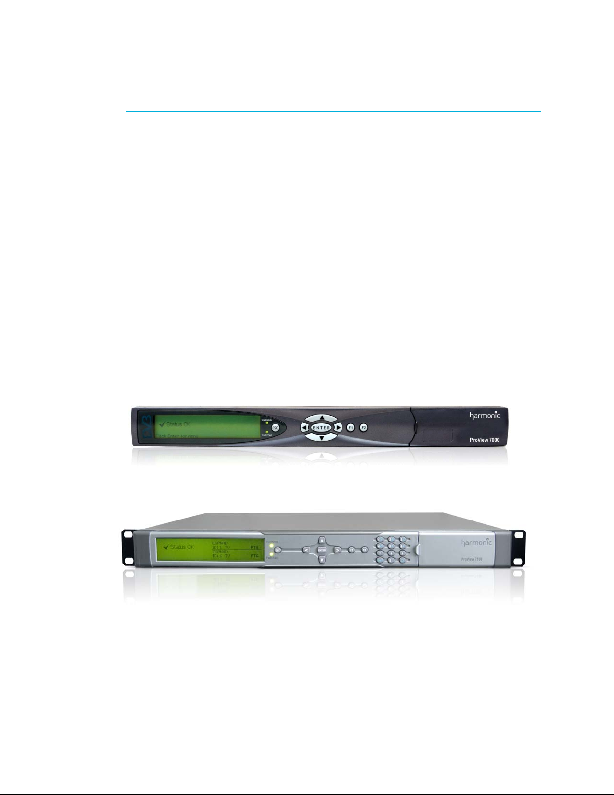
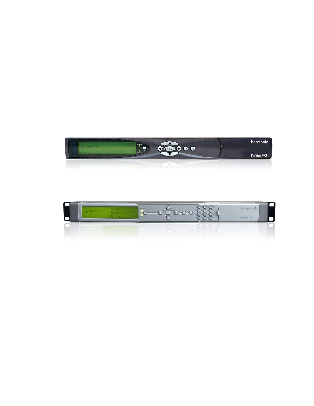
The ProView 7000™ platform is housed in a 19" 1RU mount ready enclosure. See Figure 1–1.
It includes fans for right to left air passage for side-to-side heat dissipation, the
ProView 7000™ may be installed in a rack without spacing between units. This allows
increased flexibility for installation of a large number of units in limited space environments
and integration with additional DVB equipment.
1.4.2 ProView 7000™/7100 Front Panel
The front panel of the ProView 7000™/7100 platform provides an interface to locally manage
and operate the unit.
Figure 1–1: ProView 7000™ Platform General View
Figure 1–2: ProView 7100™ Platform General View
The front panel includes, a large LCD display for menus and statuses, four direction buttons,
an <ENTER> key an <Esc> key and two F keys.
Two LEDs show the WARNING and PWR/FAIL statuses.
A two or four slot DVB-CI (DVB Common Interface/smart card interface) enables using up to
two Conditional Access Modules (CAMs) for stream descrambling.
See 3.1 Main Elements and Structure for a description of the front panel.
1.4.3 ProView 7000™ Rear Panel
The rear panel of the ProView 7000™ platform includes all of the required professional input
and output connectors. The AC connector and power switch are also located on the rear
panel as well as the GND lug for grounding the unit when installed in a rack. The rear panel is
provided in various configurations as required for different applications. See B.6 Front End
Card Features for a description of the ports and connectors.
© 2012 Harmonic Inc. 17 ProView 7000 v.2.6, Rev. E

Chapter 1 Introduction ProView 7000™ Management
1.5 ProView 7000™ Management
The ProView 7000™ Platform provides a wide range of methods for local and remote
monitoring and management:
Front Panel Control
The ProView 7000™/7100 front panel provides an easy to use management interface using
the large LCD screen and intuitive controls.
Remote Element Management System (EMS)
The ProView 7000™/7100 EMS provides an extensive GUI for managing the device over a
LAN.
Network Management System
The ProView 7000™/7100 platform provides monitoring access to Network Management
Systems using its SNMP agent.
ProView 7000™/7100 Redundancy
Use NMX management for redundancy to ensure continued service in the event that a device
malfunctions. You can use a single or multiple backup ProView 7000™/7100s to ensure
continued service with a single or multiple primary ProView 7000™/7100s. This feature is
limited to the management of up to 2 output ports, ASI or SDI.
NOTE: The devices must be identical in hardware configuration, port structure and license.
See the Harmonic NMX Installation/Setup Guide for operating instructions.
© 2012 Harmonic Inc. 18 ProView 7000 v.2.6, Rev. E
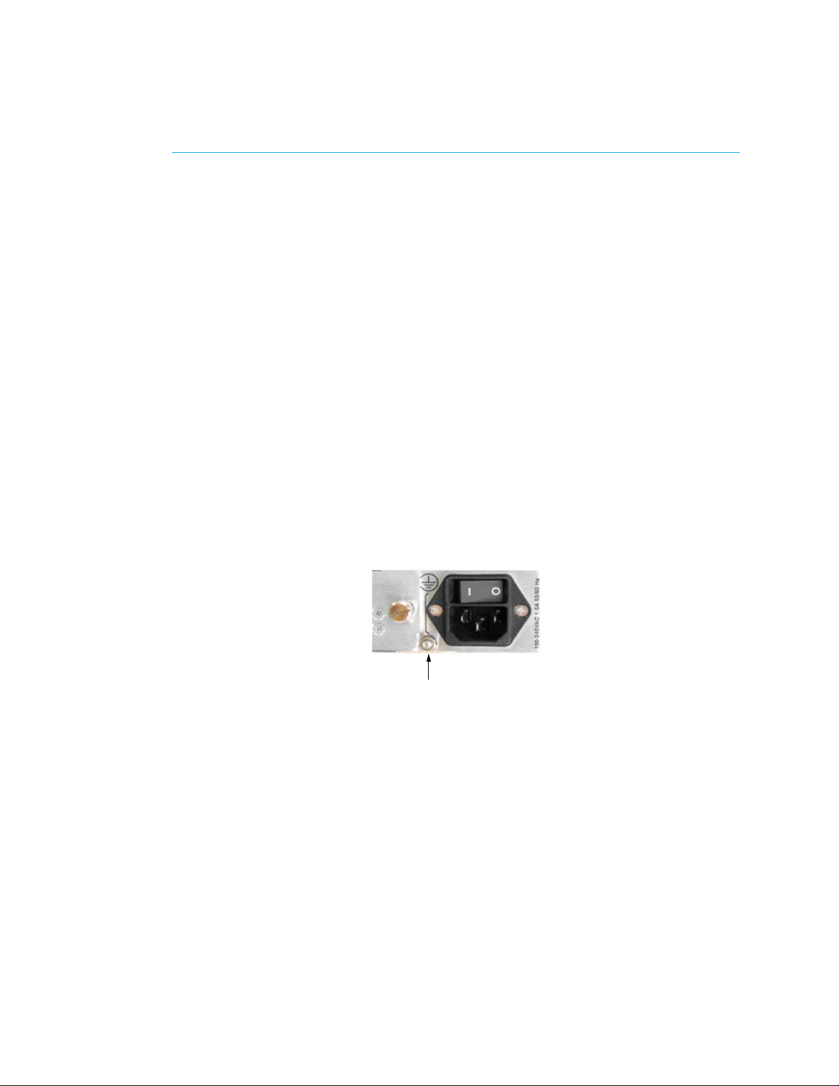
This chapter provides instructions for quick initial setup of the ProView 7000™.
Grounding Jackscrew
To pi c s:
■ Installation and Cable Connection
■ Switching On
■ Configuring the IP Parameters
■ Configuring and Monitoring
2.1 Installation and Cable Connection
Refer to the ProView 7000™ Hardware Installation Guide for detailed information on
installation and cable connection.
2.1.1 Installation
The ProView 7000™ can be installed in a 19" rack using mounting slides.
Chapter 2
Quick Start
2.1.2 Electrical connection
The ProView 7000™ is powered by an AC power supply. Grounding of the ProView 7000™ is
provided when the AC power cable is connected to the unit AC connector.
When the ProView 7000™ is rack-mounted, the device’s grounding jackscrew must be
connected to the rack housing, which must be correctly grounded.
© 2012 Harmonic Inc. 19 ProView 7000 v.2.6, Rev. E

Chapter 2 Quick Start Switching On
2.1.3 Cable Connections
Connect the remaining cables:
■ DVB-S/S2
■ ASI
■ LAN
■ Video output
■ Video monitor
2.2 Switching On
Switch the unit on with the rear power switch.
Once the boot process is completed (after 2-3 minutes) the Status OK message displays on
the front panel LCD.
No Service Selected
Status OK
2.3 Configuring the IP Parameters
To configure the IP parameters of a ProView 7000™:
1. Press <ENTER> on the keypad.
The root menu displays.
2. Navigate Unit > Management Port > IP Configuration.
IP Configuration
1 IP Address
2 Subnet Mask
3 Default Gateway
No Service Selected
127.000.000.010
255.255.255.000
000.000.000.000
3. Set the IP Address, Subnet Mask and Default Gateway for the port.
4. After any change in the IP configuration, the Apply port changes item is added to the IP
Configuration sub-menu to allow confirmation of the port setup.
5. Select Apply port changes.
6. Select Apply Changes.
© 2012 Harmonic Inc. 20 ProView 7000 v.2.6, Rev. E

Chapter 2 Quick Start Configuring and Monitoring
2.4 Configuring and Monitoring
You can configure the ProView 7000™ using the front panel or remotely using EMS over the
LAN.
The ProView 7000™ EMS application provides a GUI for easy remote management of
ProView 7000™s. For EMS system requirements see 6.2 EMS System Requirements on
page 64.
To configure the ProView 7000™ using the front panel, see Front Panel Overview on page 32
and Device Configuring Using the Front Panel on page 36.
To monitor the ProView 7000™ using the front panel, see Monitoring Using the Front Panel
on page 58.
To configure the ProView 7000™ using EMS, see Remote Management using EMS on page 63
and Device Configuring Using EMS on page 74.
To monitor the ProView 7000™ using EMS, see Monitoring using EMS on page 167.
Related topics:
■ A Typical ProView 7000™ Configuration Using the Front Panel
■ EMS Initial Setup
■ A Typical ProView 7000™ Configuration Using EMS
2.4.1 A Typical ProView 7000™ Configuration Using the Front Panel
The ProView 7000™ has four logical multiplexes. A license is required for using more than one
multiplex. Some hardware configurations support up to four satellite RF inputs.
The basic order of configuring the ProView 7000™ is:
1. Configure a DVB-S/S2 input port.
2. Descramble selection – Associate a CAM slot to a multiplex in port and enable
descrambling mode.
3. DVB-S/S2 Input Port association – The DVB-S/S2 In ports in are associated by default to
multiplex ins according to their index numbers (1–4), therefore DVB-S/S2 In Port 1 is
associated to DVB Multiplex In 1. You can associate different ports or additional ports to
Multiplex Ins.
NOTE: If the input is MPEG then change the table extraction of either a multiplex in or a multiplex out to
PSI Only before you associate the respective multiplex, see 7.2 Multiplex Inputs and 7.3 Multiplex &
Decoding Outputs.
4. Stream and Program Routing – Associate input streams to device outputs.
5. Select programs for descrambling.
6. Decoder configuration.
© 2012 Harmonic Inc. 21 ProView 7000 v.2.6, Rev. E

Chapter 2 Quick Start Configuring and Monitoring
To configure the ProView 7000™ using the Front Panel:
1. If the input stream is received from a satellite, navigate
Root > Reception > SAT (no.) > Configuration and configure the receiver parameters
according to your satellite parameters, see 4.1 Configuring the DVB-S/S2 Input Port
Properties for details.
2. If the input stream is received from IP, perform the following to configure the GbE port:
aNavigate Root > GbE > GbE Port (1 or 2) > IP Configuration.
b Configure the IP Address and Subnet Mask.
c Select Apply Port Changes.
d Select Apply Changes.
eNavigate Root > GbE > GbE Port (1 or 2) > Admin Status.
f Set the Admin Status to Up.
gNavigate Root > GbE > Socket Configuration > Socket In > Socket (no.) >
Traffic Parameters.
h Configure the IP Address Type, UDP Port and IP Address if you are using Multicast.
iNavigate Root > GbE > Socket Configuration > Socket In > Socket (no.).
j Configure the Socket De-Jittering Mode, SSM and Socket Admin Status.
3. If the output stream is sent to IP, perform the following to configure the GbE port:
aNavigate Root > GbE > GbE Port (1 or 2) > IP Configuration.
b Configure the IP Address, Subnet Mask and Default Gateway.
c Select Apply Port Changes.
d Select Apply Changes.
eNavigate Root > GbE > GbE Port (1 or 2) > Admin Status.
f Set the Admin Status to Up.
gNavigate Root > GbE > Socket Configuration > Socket Out > Socket (no.).
h Configure the Destination IP Address and the Destination UDP Port.
i Set the Socket Status to Up.
4. If you wish to descramble, you must associate the CAM to the multiplex:
aNavigate Root>CAM>CAM(1–4)>CAM Association.
b Select a multiplex, TS1, TS2, TS3 or TS4.
The descrambling mode default is Selective, you can change the mode to Full.
5. To access the CAM MMI menu, select CAM MMI.
6. Select a DVB-S/S2 input port:
aNavigate Root > Routing and Descrambling > TS (no.) > Input Selection.
b Select an input port for the received transport stream (Options: SAT (1–4), ASI (1–4)).
7. Select Input Type, (Options: MPEG and DVB). This also sets the respective PSI/SI tables for
the output stream.
NOTE: The default option for stream type is DVB. For ATSC systems, set the stream type to MPEG.
© 2012 Harmonic Inc. 22 ProView 7000 v.2.6, Rev. E

Chapter 2 Quick Start Configuring and Monitoring
8. To configure the multiplex output:
aNavigate Root > Routing and Descrambling > TS (no.) > Output Selection.
b Select one or more outputs for the received transport stream (Options: ASI (1–2),
Socket (1–4).) The four sockets are virtual and must be associated to a physical GbE
port.
c Select Enable in each output sub-menu that you select.
NOTE: In this mode, stream information is not processed and output bit rate is identical to input bit rate.
dNavigate Root > Routing and Descrambling > TS (no.) > Activation.
e Select Enable.
9. To select a program for descrambling:
aNavigate Root > Routing and Descrambling > TS (no.) > Descrambling.
A list of all input programs received displays.
Program name, program ID, program type and program scrambling state display.
Name Id Device
1BBC ID:4301 TV CAS
2CNN ID:4302 TV CAS
3 IBA 2 ID:4308 AUDIO FTA
4 MI-TV ID:8025 TV FTA
Mode
b Select a program for descrambling.
c Select CAM Selection.
d Select CAM 1, 2, 3 or 4 to associate the program to it.
Repeat steps 6 to 9 for each multiplex that you wish to use (1–4).
10. Navigate Root > Decoding > Decoder (no.) > Configuration> Input Selection.
If you only have a single decoder then their is no Decoder (no.) menu.
11. Select a multiplex, 1, 2, 3 or 4, for input.
12. Set the Service Selection Mode:
aNavigate
Root > Decoding > Decoder (no.) > Configuration > Service Selection Mode.
If you only have a single decoder then their is no Decoder (no.) menu.
b Select Program Selection.
© 2012 Harmonic Inc. 23 ProView 7000 v.2.6, Rev. E

Chapter 2 Quick Start Configuring and Monitoring
13. Navigate Root > Decoding > Decoder (no.) > Configuration> Programs.
If you only have a single decoder then their is no Decoder (no.) menu.
Name ID Type
1 ƒ BBC 4301 TV CAS
2 ‚ CNN 4302 TV CAS
3 ‚ IBA 2 4308 AUDIO FTA
Mode
The Programs menu displays a list of programs available on the input transport stream
and enables you to select the program to be decoded.
The screen displays the program name if the input stream provides an SDT table, the
program ID (decimal number), the program type (TV or Radio) and the program mode
(CAS/scrambled or FTA/free to air).
Only one program can be selected (radio button selection).
14. Navigate
Root > Decoding > Decoder (no.) > Configuration> Descrambling > CAM Selection.
If you only have a single decoder then their is no Decoder (no.) menu.
15. Select the CAM slot.
© 2012 Harmonic Inc. 24 ProView 7000 v.2.6, Rev. E
Chapter 2 Quick Start Configuring and Monitoring
2.4.2 EMS Initial Setup
Before you can manage a ProView 7000™ remotely, you must configure the IP parameters,
see 2.3 Configuring the IP Parameters on page 20.
To pi c s:
■ Installing EMS
■ Launching EMS
■ Adding a Device
2.4.2.1 Installing EMS
The ProView 7000™ EMS is stored in the ProView 7000™ for easy installation using a web
browser.
To install the ProView 7000™ EMS:
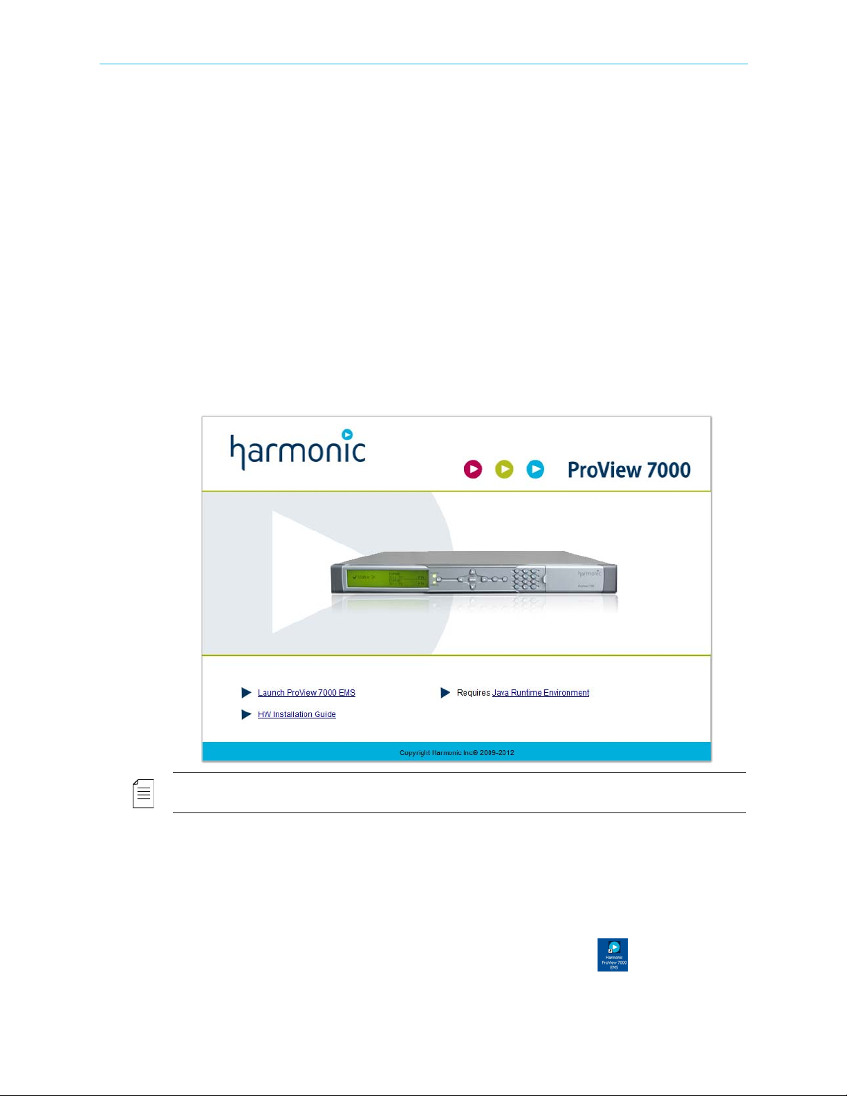
1. Run a web browser and enter the ProView 7000™ IP address.
The initial ProView 7000™ dialog displays.
NOTE: The EMS application is a Java-based program which requires Java Runtime Environment version
1.6. If needed, install Java Runtime Environment 1.6, using the link provided on the Java Web start page
To check the ProView 7000™ EMS Java version:
aRun
bEnter
cmd in Windows.
Java -version and press Enter to check which version is currently on your
station. Update if necessary from the Java Web start page.
2. Click Launch ProView 7000 EMS on the ProView 7000™ web page to install the EMS.
The EMS application installs. Shortcuts are added to the desktop and the start
menu.
© 2012 Harmonic Inc. 25 ProView 7000 v.2.6, Rev. E
Chapter 2 Quick Start Configuring and Monitoring
2.4.2.2 Launching EMS
Prerequisites:
The device IP address must be configured using the ProView 7000™ front panel, see
2.3 Configuring the IP Parameters.
To launch the ProView 7000™ EMS:
❖ Double-click the Harmonic ProView 7000™ EMS launch icon to launch EMS.
The EMS GUI displays.
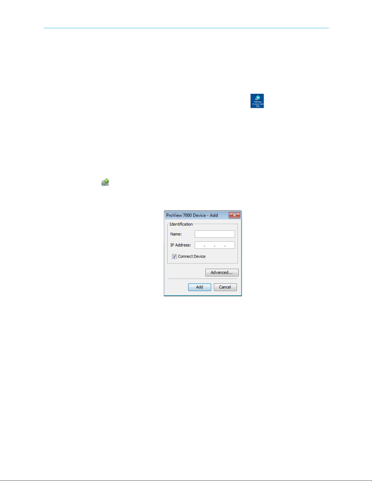
2.4.2.3 Adding a Device
The IP Address is the same one you configured in 2.3 Configuring the IP Parameters on
page 20. For details on usernames and passwords see 7.10.5 Log-In / Log-Out Control of the
Device on page 147 and 7.11.4 Device Users’ Access Properties on page 162.
To add a device:
1. Click Add Device on the EMS toolbar
—or—
select Administration > Add ProView 7000.
Figure 2–1: Add Device dialog
The EMS displays the Add ProView 7000™ Device dialog.
2. Enter a name for the new ProView 7000™ device.
3. Enter the IP Address of the new ProView 7000™ device.
4. For automatic connection when launching the EMS, mark the Connect Device
checkbox.
5. Click Add.
The Log In dialog displays.
6. Select a username from the drop down menu, configure or monitor, the password is the
same as the username by default.
The device connects automatically.
© 2012 Harmonic Inc. 26 ProView 7000 v.2.6, Rev. E

Chapter 2 Quick Start Configuring and Monitoring
If the device fails to connect, perform the following:
a Right-click the device icon in the Device box and select Ping in the device context
menu.
bClick Ping in the Ping dialog box.
c If the ping fails, check your network connections and settings.
d Right-click the device icon in the Device box and select Connect in the device context
menu.
2.4.3 A Typical ProView 7000™ Configuration Using EMS
The ProView 7000™ has four logical multiplexes. A license is required for using more than one
multiplex. Some hardware configurations support up to four satellite RF inputs. All
ProView 7000™s have 2 GbE data ports.
The EMS enables building your own decoded output stream, by selecting specific elementary
stream from a program. Drag and drop the ES icon from the input program branch onto the
Output decoding icon. The ES Decoding Properties dialog displays, allowing you to set the
relevant parameters. Do not use ESs from different programs.
TIP: Descrambling Set-Up TIP:
When setting a program or an ES for decoding, the decoder properties menu enables the user to
descramble the program and to select the CAM slot for the descrambling process.
For a detailed description of the options provided by the Decoding Channel Properties dialog see
7.3.8 Decoding Channel Properties.
The basic order of configuring the ProView 7000™ is:
1. Configure a DVB-S/S2 input port.
2. Descramble selection – The CAM Slot Properties dialog monitors and manages the
selected CAM slot element. It enables you to associate a CAM slot to a multiplex in port
and enable descrambling mode.
3. Descrambling a Program – Select individual programs to descramble.
4. Input Port association – The DVB-S/S2 In ports in the Physical Input box are associated by
default to multiplex ins in the Multiplex Input box according to their index numbers (1–4),
therefore DVB-S/S2 In Port 1 is associated to DVB Multiplex In 1. You can associate
different ports or additional ports to Multiplex Ins.
© 2012 Harmonic Inc. 27 ProView 7000 v.2.6, Rev. E
Chapter 2 Quick Start Configuring and Monitoring
NOTE: If the input is MPEG then change the table extraction of either a multiplex in or a multiplex out to
PSI Only before you associate the respective multiplex, see 7.2.4 Multiplex In Port Properties and
7.3.2 Multiplex Output Properties.
5. Stream and Program Routing – Drag-and-drop routing of input streams to device outputs.
6. Decoder Configuration.
To configure the ProView 7000™ using EMS:
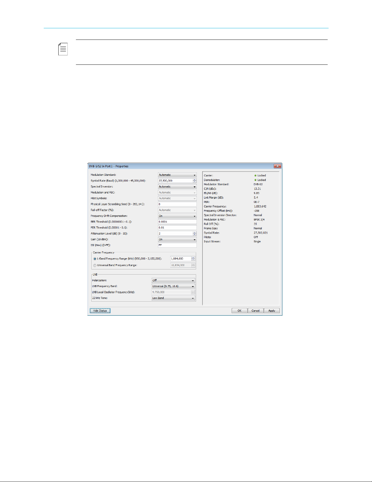
1. If the input stream is received from satellite, perform the following to display and
configure a DVB-S/S2 input port:
a Expand the device tree in the Physical Input box to reveal the DVB in ports.
b Select the required DVB-S/S2 in port icon in the Physical Input box.
cClick Properties on the EMS toolbar.
dClick Show Status in the bottom left corner of the properties dialog.
The displayed properties are divided into two sections; the section on the left
displays editable properties and the section on the right provides informative/status
properties that cannot be edited by the EMS user.
e Configure the properties in the left section and click Apply.
2. If the input stream is received from IP, perform the following to display and configure the
GbE port:
a Select the device in the Devices box.
b Expand the device tree in the Physical Input box to reveal the GbE ports.
c Select the required GbE port icon in the Physical Input box.
dClick Properties on the EMS toolbar.
e Configure the GbE port, see 7.1.3 GbE Ports for Input for details.
f Select a socket in the GbE branch in the Physical Input box.
© 2012 Harmonic Inc. 28 ProView 7000 v.2.6, Rev. E
Chapter 2 Quick Start Configuring and Monitoring
gClick Properties on the EMS toolbar.
h Configure the socket, see 7.1.3.2 GbE Socket Properties for details.
3. If the output stream is sent to IP, perform the following to configure the GbE port:
a Select the device in the Devices box.
b Expand the device tree in the Physical Output box to reveal the GbE ports.
c Select the required GbE port icon in the Physical Output box.
dClick Properties on the EMS toolbar.
e Configure the GbE port, see 7.1.3 GbE Ports for Input for details.
f Select a socket in the GbE branch in the Physical Output box.
gClick Properties on the EMS toolbar.
h Configure the socket, see 7.4.2.2 GbE Socket Properties for details.
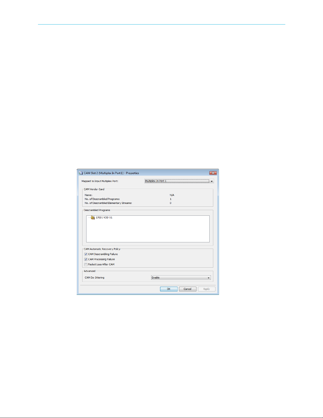
4. To associate a multiplex in port to a CAM Slot:
a Select the required CAM Slot name in the Physical Input box.
bClick Properties on the EMS toolbar.
The dialog displays with the programs descrambled by the slot.
c Select a multiplex in port to connect to the CAM slot.
5. To descramble a program:
a Right-click a program in the Multiplex & Decoding Output box.
b Select Properties.
The Program Properties dialog displays.
cMark the Descramble with checkbox.
d Select a CAM slot.
eClick Apply.
© 2012 Harmonic Inc. 29 ProView 7000 v.2.6, Rev. E
Chapter 2 Quick Start Configuring and Monitoring
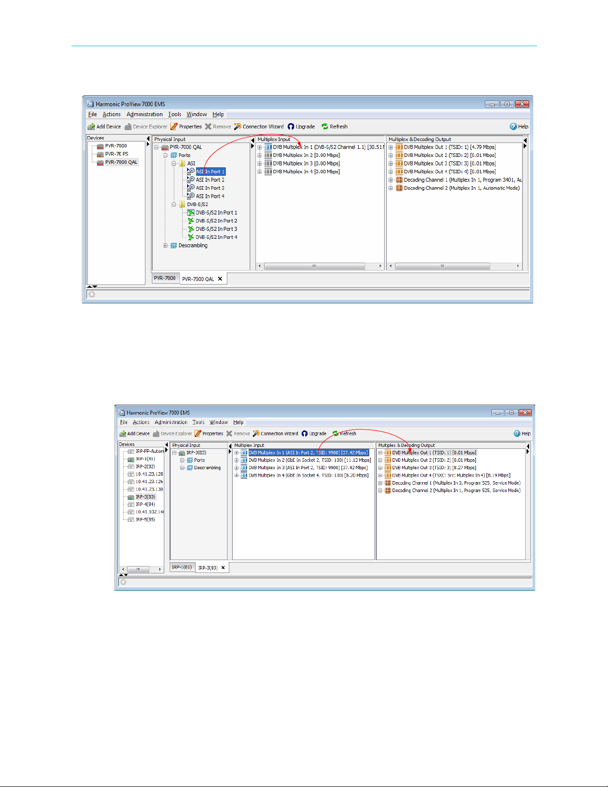
6. To associate a different port or additional ports to a Multiplex In:
aDrag a Port from the Physical Input box to a Multiplex In in the Multiplex Input box.
A confirmation dialog displays.
bClick Yes to create the association.
7. To cross-connect an input transport stream, a program, an EMM in a conditional access
table (CAT) or even an unreferenced PID:
a Drag the item from the Multiplex Input box and drop it into the Multiplex & Decoding
Output box.
The Cross-Connect configuration dialog displays for you to configure the parameters
of the routed element.
b Configure the desired parameters and click Create to create the cross-connect.
© 2012 Harmonic Inc. 30 ProView 7000 v.2.6, Rev. E
 Loading...