

Harmonic ProView 7000 User Manual

ProView 7000™
Integrated Receiver and Stream Processor
User Manual
VERSION 2.4
Rev. A
Manual Part No. MAN-PVR-7K-2.4

Disclaimer
Harmonic reserves the right to alter the equipment specifications and descriptions in this publication without prior notice. No part of
this publication shall be deemed to be part of any contract or warranty unless specifically incorporated by reference into such
contract or warranty. The information contained herein is merely descriptive in nature, and does not constitute a binding offer for
sale of the product described herein. Harmonic assumes no responsibility or liability arising from the use of the products described
herein, except as expressly agreed to in writing by Harmonic. The use and purchase of this product do not convey a license under
any patent rights, copyrights, trademark rights, or any intellectual property rights of Harmonic. Nothing hereunder constitutes a
representation or warranty that using any products in the manner described herein will not infringe any patents of third parties.
Trademark Acknowledgments
Harmonic and all Harmonic product names are trademarks of Harmonic Inc. All other trademarks are the property of their respective
owners.
Compliance and Approval
This equipment generates, uses, and can radiate radio frequency energy. It may cause harmful interference to radio communications
if it is not installed and used in accordance with the instructions in this manual. Operation of this equipment in a residential area is
likely to cause harmful interference. If this occurs, the user will be required to correct the interference at his or her own expense.
This equipment has been tested and found to comply with the limits for a Class A digital device, pursuant to Part 15, Subpart B of the
Federal Communications Commission (FCC) rules.
These limits are designed to provide reasonable protection against harmful interference when the equipment is operated in a
commercial environment.
This device complies with Part 15 of the FCC rules. Operation is subject to the following two conditions: (1) this device may not
cause harmful interference, and (2) this device must accept any interference received, including interference that may cause
undesired operation.
Connections between the Harmonic equipment and other equipment must be made in a manner that is consistent with maintaining
compliance with FCC radio frequency emission limits. Modifications to this equipment not expressly approved by Harmonic may
void the authority granted to the user by the FCC to operate this equipment.
WEEE/RoHS Compliance Policy
Harmonic Inc. intends to comply fully with the European Union’s Directive 2002/96/EC as amended, on Waste Electrical and
Electronic Equipment, also known as “WEEE,” and Directive 2002/95/EC, as amended, on the Restriction of use of Hazardous
Substances, also known as “RoHS.”
Harmonic will ensure that product which cannot be reused will be recycled in compliance with the WEEE Directive. To that end,
users are advised that (1) Harmonic equipment is not to be discarded in household or office garbage, (2) Harmonic Inc. will pay the
freight for shipment of equipment to be disposed of if it is returned to Harmonic, (3) customers should call the normal RMA
telephone numbers to arrange for such shipment, and (4) for additional and updated information on this process customers may
consult the Harmonic website: http://harmonicinc.com/pa_weee_recycle.cfm.
Harmonic will ensure that its products will be either reused or recycled in compliance with the WEEE Directive. For the latest
information concerning Harmonic’s WEEE/RoHS Compliance Policy and its Recycling and Take-Back process, please visit our web
site.
© 2011 Harmonic Inc. All rights reserved.
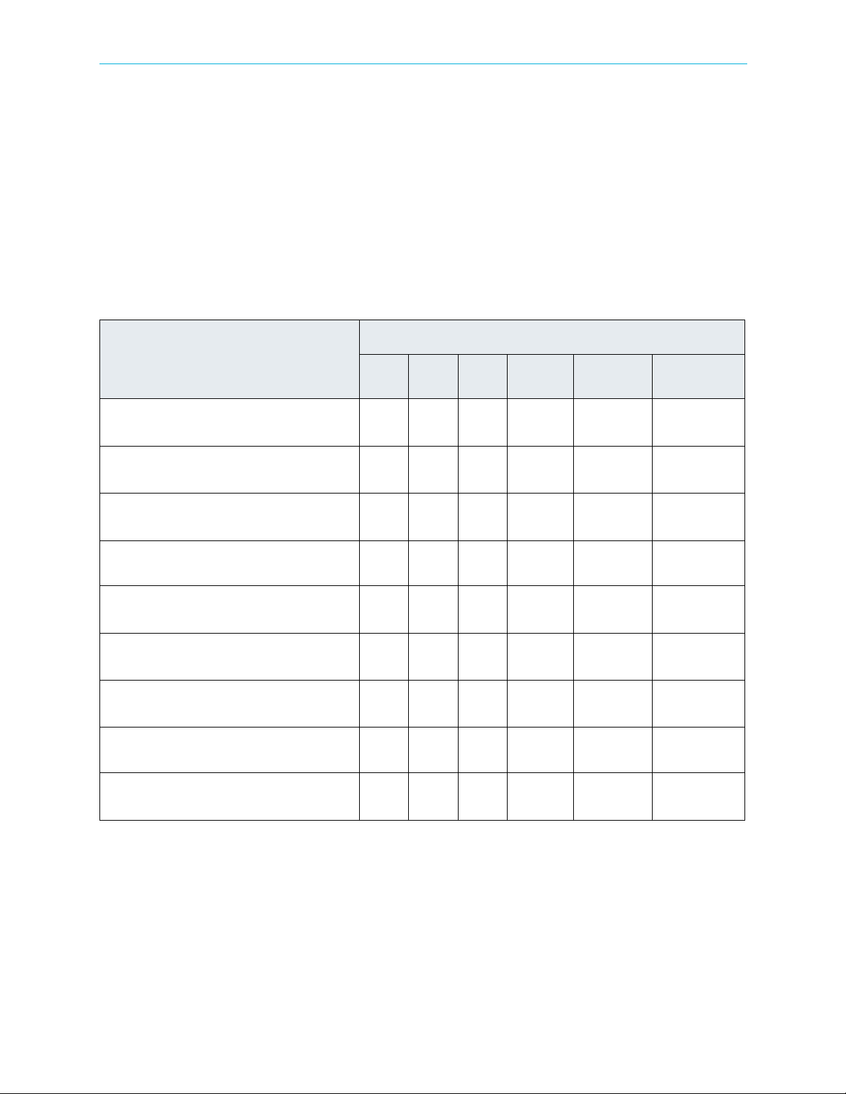
产品中的有毒有害物质或元素的名称及含量表
Names and Contents of the Toxic and Hazardous Substances or Elements in the
Products if the Part is Present
该表显示哈雷公司产品中可能含有的有毒有害物质元配件的信息,除了来源于元配件供应商的物料成分资料,
亦来自其它相关的机构与资料。哈雷产品不一定使用这些元配件。
This table shows those components where hazardous substances may be found in Harmonic products based on, among other
things, material content information provided by third party suppliers. These components may or may not be part of the product.
除非特殊注明,哈雷公司产品的环保使用期限 均为 20 年。该环保使用期限的有效条件为:必须遵循该产品使
用手册的规定,对该产品进行使用或存储。
The Environmental Protective Use Period for Harmonic products is 20 years unless displayed otherwise on the product. The EPUP
period is valid only when the products are operated or stored as per the conditions specified in the product manual.
有毒有害物质或元素 (Hazardous Substance)
部件名称 (Part name)
铅
(PB) 汞(Hg)镉(Cd)
六价铬
(CrVI)
多溴联苯
(PBB)
多溴二苯醚
(PBDE)
印刷线路板
(Printed Circuit Assemblies)
机械组件
(Mechanical Subassemblies)
光学组件
(Optical Subassemblies)
电源
(Power Supplies)
缆线 / 线束
(Cables, harnesses)
屏幕 / 显示器
(Screens, Monitors)
金属零件
(Metal Parts)
塑
料 / 发泡材料
(Plastics, foams)
电池
(Batteries)
XOO O O O
XOO O O O
XOO O O O
XOO O O O
XOO O O O
XOO O O O
OOO O O O
OOO O O O
XOO O O O
O: 表示在该部件的所有均质材料中,此类有毒有害物质的含量均小于 SJ/T11363-2006 标准所规定的限量。
O: Indicates the content of the toxic and hazardous substances at the homogeneous material level of the parts is below the limit
defined in SJ/T11363 2006 standard.
X: 表示至少在该部件的某一均质材料中,此类有毒有害物质的含量超出 SJ/T11363-2006 标准规定的限量。
X: Indicates that the content of the toxic and hazardous substances in at least one of the homogeneous materials of the parts is
above the limit defined in SJ/T11363 2006 standard.
© 2011 Harmonic Inc. All rights reserved.
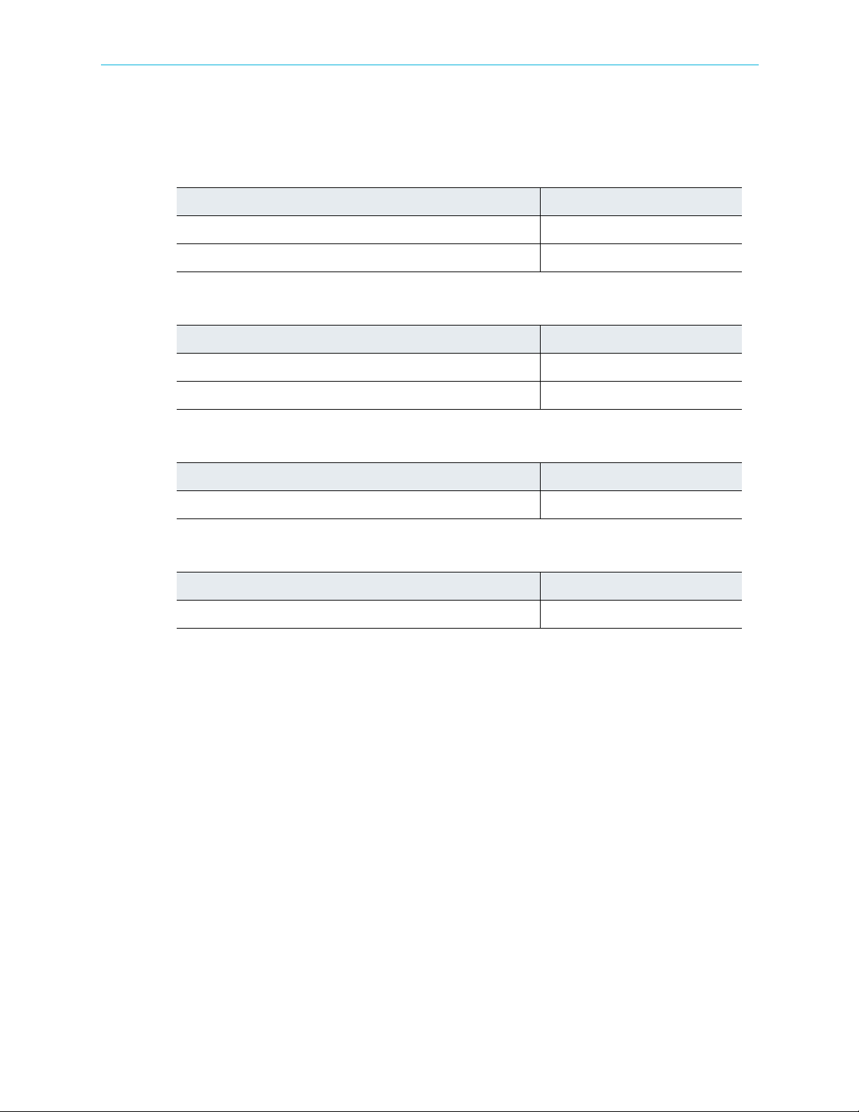
Standards and Agency Approval
The following tables list regulatory standards and agency approvals:
North America
Standards Agency Approval
EMI: FCC Part 15, Subpart B, ICES-003, Issue 2, Class A FCC
Safety: UL 60950-1, CSA 60950-1 cTUV-us Mark
Europe
Standards Agency Approval
EMI/EMC: EN55022, Class A, EN55024 CE
Safety: EN 60950-1, EN60825-1 TUV-GS or T-Mark, CE
Japan
Standards Agency Approval
EMI: VCCI V-3 2009 VCCI
Australia and New Zealand
EMI: AS/NZS CISPR22:2006 N/A
Standards Agency Approval
© 2011 Harmonic Inc. All rights reserved.
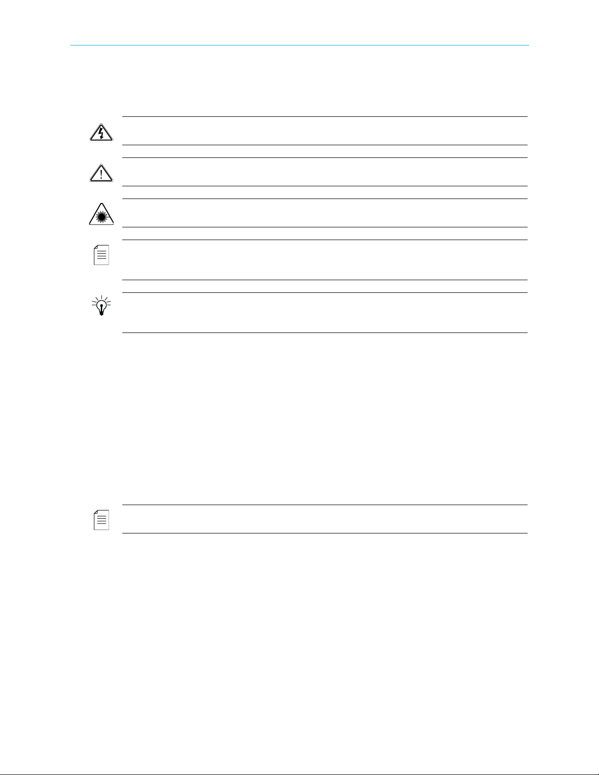
Documentation Conventions
This manual uses some special symbols and fonts to call your attention to important information. The
following symbols appear throughout this manual:
DANGER: The Danger symbol calls your attention to information that, if ignored, can cause physical
harm to you.
CAUTION: The Caution symbol calls your attention to information that, if ignored, can adversely affect
the performance of your Harmonic product, or that can make a procedure needlessly difficult.
LASER DANGER: The Laser symbol and the Danger alert call your attention to information about the
lasers in this product that, if ignored, can cause physical harm to you.
NOTE: The Note symbol calls your attention to additional information that you will benefit from
heeding. It may be used to call attention to an especially important piece of information you need, or it
may provide additional information that applies in only some carefully delineated circumstances.
TIP: The Tip symbol calls your attention to parenthetical information that is not necessary for performing
a given procedure, but which, if followed, might make the procedure or its subsequent steps easier,
smoother, or more efficient.
In addition to these symbols, this manual uses the following text conventions:
■ Data Entry: indicates text you enter at the keyboard.
■ User Interface: indicates a button to click, a menu item to select, or a key or key sequence to
press.
■ Screen Output: shows console output or other text that is displayed to you on a
computer screen.
■ Bold: indicates the definition of a new term.
■ Italics: used for emphasis, cross-references, and hyperlinked cross-references in online
documents.
NOTE: You require Adobe Reader or Adobe Acrobat version 6.0 or later to open the PDF files. You can
download Adobe Reader free of charge from www.adobe.com.
© 2011 Harmonic Inc. All rights reserved.

Table of Contents
Table of Contents
Chapter 1 Introduction
1.1 General Information . . . . . . . . . . . . . . . . . . . . . . . . . . . . . . . . . . . . . . . . . . . . . . . . . 11
1.2 Main ProView 7000 Applications. . . . . . . . . . . . . . . . . . . . . . . . . . . . . . . . . . . . . . . 11
1.2.1 TS Descrambling Applications . . . . . . . . . . . . . . . . . . . . . . . . . . . . . . . . . . . . . . . . . 11
1.2.2 Decoding Applications . . . . . . . . . . . . . . . . . . . . . . . . . . . . . . . . . . . . . . . . . . . . . . . 12
1.3 ProView 7000 Platform Main Features and Configurations . . . . . . . . . . . . . . . . . 12
1.3.1 Multi-Transport Stream Descrambler . . . . . . . . . . . . . . . . . . . . . . . . . . . . . . . . . . .13
1.3.2 Multi-Format Decoder . . . . . . . . . . . . . . . . . . . . . . . . . . . . . . . . . . . . . . . . . . . . . . . 14
1.3.3 DMS (Distribution Management System) . . . . . . . . . . . . . . . . . . . . . . . . . . . . . . . . 16
1.4 ProView 7000 Mechanical Structure . . . . . . . . . . . . . . . . . . . . . . . . . . . . . . . . . . . . 16
1.4.1 ProView 7000 Enclosure . . . . . . . . . . . . . . . . . . . . . . . . . . . . . . . . . . . . . . . . . . . . . . 16
1.4.2 ProView 7000 Front Panel . . . . . . . . . . . . . . . . . . . . . . . . . . . . . . . . . . . . . . . . . . . . 16
1.4.3 ProView 7000 Rear Panel . . . . . . . . . . . . . . . . . . . . . . . . . . . . . . . . . . . . . . . . . . . . . 17
1.5 ProView 7000 Management . . . . . . . . . . . . . . . . . . . . . . . . . . . . . . . . . . . . . . . . . . . 17
Chapter 2 Hardware Installation
2.1 Safety Precautions. . . . . . . . . . . . . . . . . . . . . . . . . . . . . . . . . . . . . . . . . . . . . . . . . . . 18
2.2 Inventory Check. . . . . . . . . . . . . . . . . . . . . . . . . . . . . . . . . . . . . . . . . . . . . . . . . . . . . 18
2.3 Power Supply to the Unit . . . . . . . . . . . . . . . . . . . . . . . . . . . . . . . . . . . . . . . . . . . . . 19
2.4 Installing the Unit in a Rack. . . . . . . . . . . . . . . . . . . . . . . . . . . . . . . . . . . . . . . . . . . 19
2.4.1 Fitting the Brackets. . . . . . . . . . . . . . . . . . . . . . . . . . . . . . . . . . . . . . . . . . . . . . . . . . 19
2.4.2 Installing the L Shape Slides. . . . . . . . . . . . . . . . . . . . . . . . . . . . . . . . . . . . . . . . . . . 19
2.4.3 Mounting ProView 7000 units in the 19" Rack . . . . . . . . . . . . . . . . . . . . . . . . . . . 20
2.5 Insertion of the DVB-CI Module (PCMCIA) . . . . . . . . . . . . . . . . . . . . . . . . . . . . . . . 21
2.6 Electrical Power Connection. . . . . . . . . . . . . . . . . . . . . . . . . . . . . . . . . . . . . . . . . . . 21
2.7 Connecting the Cables . . . . . . . . . . . . . . . . . . . . . . . . . . . . . . . . . . . . . . . . . . . . . . . 22
2.8 Switching On . . . . . . . . . . . . . . . . . . . . . . . . . . . . . . . . . . . . . . . . . . . . . . . . . . . . . . .23
Chapter 3 Configuration and Monitoring
3.1 Configuring the IP Parameters . . . . . . . . . . . . . . . . . . . . . . . . . . . . . . . . . . . . . . . . . 24
3.2 The ProView 7000 EMS. . . . . . . . . . . . . . . . . . . . . . . . . . . . . . . . . . . . . . . . . . . . . . . 24
3.2.1 EMS System Requirements. . . . . . . . . . . . . . . . . . . . . . . . . . . . . . . . . . . . . . . . . . . . 24
3.2.2 Installing EMS . . . . . . . . . . . . . . . . . . . . . . . . . . . . . . . . . . . . . . . . . . . . . . . . . . . . . . 25
3.2.3 Launching the ProView 7000 EMS. . . . . . . . . . . . . . . . . . . . . . . . . . . . . . . . . . . . . . 26
3.3 How to Configure and Monitor the ProView 7000. . . . . . . . . . . . . . . . . . . . . . . . . 28
3.3.1 Configuring the ProView 7000 using the Front Panel . . . . . . . . . . . . . . . . . . . . . . 28
3.3.2 Monitoring the ProView 7000 using the Front Panel. . . . . . . . . . . . . . . . . . . . . . . 31
3.3.3 Configuring the ProView 7000 using EMS . . . . . . . . . . . . . . . . . . . . . . . . . . . . . . . 32
3.3.4 Monitoring the ProView 7000 using EMS . . . . . . . . . . . . . . . . . . . . . . . . . . . . . . . . 38
3.4 Low Delay Mode . . . . . . . . . . . . . . . . . . . . . . . . . . . . . . . . . . . . . . . . . . . . . . . . . . . . 38
3.4.1 Selecting Low Delay Mode . . . . . . . . . . . . . . . . . . . . . . . . . . . . . . . . . . . . . . . . . . . . 38
© 2011 Harmonic Inc. 6 ProView 7000 v.2.4, Rev. A

Table of Contents
Chapter 4 Element Management System (EMS)
4.1 ProView 7000 EMS Structure . . . . . . . . . . . . . . . . . . . . . . . . . . . . . . . . . . . . . . . . . . 40
4.1.1 GUI Display TIPS . . . . . . . . . . . . . . . . . . . . . . . . . . . . . . . . . . . . . . . . . . . . . . . . . . . . 40
4.1.2 Devices Box . . . . . . . . . . . . . . . . . . . . . . . . . . . . . . . . . . . . . . . . . . . . . . . . . . . . . . . .42
4.1.3 Device Explorer Tabs . . . . . . . . . . . . . . . . . . . . . . . . . . . . . . . . . . . . . . . . . . . . . . . . . 42
4.1.4 Alarms Tab . . . . . . . . . . . . . . . . . . . . . . . . . . . . . . . . . . . . . . . . . . . . . . . . . . . . . . . . .42
4.1.5 Alarm History Tab . . . . . . . . . . . . . . . . . . . . . . . . . . . . . . . . . . . . . . . . . . . . . . . . . . . 44
4.1.6 EMS Status Bar . . . . . . . . . . . . . . . . . . . . . . . . . . . . . . . . . . . . . . . . . . . . . . . . . . . . . 45
4.1.7 EMS Menu . . . . . . . . . . . . . . . . . . . . . . . . . . . . . . . . . . . . . . . . . . . . . . . . . . . . . . . . . 45
4.1.8 EMS Toolbar. . . . . . . . . . . . . . . . . . . . . . . . . . . . . . . . . . . . . . . . . . . . . . . . . . . . . . . . 45
4.2 ProView 7000 EMS Menu Bar . . . . . . . . . . . . . . . . . . . . . . . . . . . . . . . . . . . . . . . . . 47
4.2.1 File Menu . . . . . . . . . . . . . . . . . . . . . . . . . . . . . . . . . . . . . . . . . . . . . . . . . . . . . . . . . .47
4.2.2 Actions Menu. . . . . . . . . . . . . . . . . . . . . . . . . . . . . . . . . . . . . . . . . . . . . . . . . . . . . . . 48
4.2.3 Administration Menu . . . . . . . . . . . . . . . . . . . . . . . . . . . . . . . . . . . . . . . . . . . . . . . . 48
4.2.4 Tools Menu. . . . . . . . . . . . . . . . . . . . . . . . . . . . . . . . . . . . . . . . . . . . . . . . . . . . . . . . .49
4.2.5 Window Menu . . . . . . . . . . . . . . . . . . . . . . . . . . . . . . . . . . . . . . . . . . . . . . . . . . . . . . 50
4.2.6 Help Menu . . . . . . . . . . . . . . . . . . . . . . . . . . . . . . . . . . . . . . . . . . . . . . . . . . . . . . . . . 50
4.3 ProView 7000 Device Management. . . . . . . . . . . . . . . . . . . . . . . . . . . . . . . . . . . . . 51
4.3.1 Accessing the ProView 7000 Device Management Functions . . . . . . . . . . . . . . . . 51
4.3.2 Device Communication Status . . . . . . . . . . . . . . . . . . . . . . . . . . . . . . . . . . . . . . . . . 53
4.3.3 Device Management Functions . . . . . . . . . . . . . . . . . . . . . . . . . . . . . . . . . . . . . . . . 53
4.4 Device Explorer . . . . . . . . . . . . . . . . . . . . . . . . . . . . . . . . . . . . . . . . . . . . . . . . . . . . . 64
4.4.1 Physical Input Box. . . . . . . . . . . . . . . . . . . . . . . . . . . . . . . . . . . . . . . . . . . . . . . . . . . 67
4.4.2 Multiplex Input Box . . . . . . . . . . . . . . . . . . . . . . . . . . . . . . . . . . . . . . . . . . . . . . . . . 69
4.4.3 Multiplex & Decoding Output Box. . . . . . . . . . . . . . . . . . . . . . . . . . . . . . . . . . . . . . 72
4.4.4 Physical Output Box . . . . . . . . . . . . . . . . . . . . . . . . . . . . . . . . . . . . . . . . . . . . . . . . . 79
4.5 Element Properties Configuration . . . . . . . . . . . . . . . . . . . . . . . . . . . . . . . . . . . . . . 80
4.5.1 Device Properties. . . . . . . . . . . . . . . . . . . . . . . . . . . . . . . . . . . . . . . . . . . . . . . . . . . . 81
4.5.2 Physical Input Ports and Slots . . . . . . . . . . . . . . . . . . . . . . . . . . . . . . . . . . . . . . . . . 93
4.5.3 Input Multiplex Properties . . . . . . . . . . . . . . . . . . . . . . . . . . . . . . . . . . . . . . . . . . .105
4.5.4 Multiplex & Decoding Output Properties . . . . . . . . . . . . . . . . . . . . . . . . . . . . . . . 110
4.5.5 Physical Output Interface Properties . . . . . . . . . . . . . . . . . . . . . . . . . . . . . . . . . . . 127
4.6 Cross Connections . . . . . . . . . . . . . . . . . . . . . . . . . . . . . . . . . . . . . . . . . . . . . . . . . . 131
4.6.1 Setting Multiplex Cross Connections. . . . . . . . . . . . . . . . . . . . . . . . . . . . . . . . . . . 132
4.6.2 Input to Decoder Channel Connection . . . . . . . . . . . . . . . . . . . . . . . . . . . . . . . . .138
4.6.3 CAM Slot Management. . . . . . . . . . . . . . . . . . . . . . . . . . . . . . . . . . . . . . . . . . . . . . 139
4.6.4 EMS Connection Wizard . . . . . . . . . . . . . . . . . . . . . . . . . . . . . . . . . . . . . . . . . . . . . 141
4.7 Refreshing the EMS Screen . . . . . . . . . . . . . . . . . . . . . . . . . . . . . . . . . . . . . . . . . .143
Chapter 5 Front Panel Interface
5.1 ProView 7000 Front Panel Operation. . . . . . . . . . . . . . . . . . . . . . . . . . . . . . . . . . .144
5.1.1 Main Elements and Structure. . . . . . . . . . . . . . . . . . . . . . . . . . . . . . . . . . . . . . . . .144
5.1.2 Front Panel Screen Types . . . . . . . . . . . . . . . . . . . . . . . . . . . . . . . . . . . . . . . . . . . .145
5.2 Front Panel Root Menu. . . . . . . . . . . . . . . . . . . . . . . . . . . . . . . . . . . . . . . . . . . . . .147
5.2.1 Reception Menu . . . . . . . . . . . . . . . . . . . . . . . . . . . . . . . . . . . . . . . . . . . . . . . . . . .149
5.2.2 Decoding Menu . . . . . . . . . . . . . . . . . . . . . . . . . . . . . . . . . . . . . . . . . . . . . . . . . . . .156
5.2.3 Routing and Descrambling Menu. . . . . . . . . . . . . . . . . . . . . . . . . . . . . . . . . . . . . . 166
© 2011 Harmonic Inc. 7 ProView 7000 v.2.4, Rev. A

Table of Contents
5.2.4 GbE Menu. . . . . . . . . . . . . . . . . . . . . . . . . . . . . . . . . . . . . . . . . . . . . . . . . . . . . . . . . 167
5.2.5 Alarms Table Menu . . . . . . . . . . . . . . . . . . . . . . . . . . . . . . . . . . . . . . . . . . . . . . . . . 169
5.2.6 Presets Menu . . . . . . . . . . . . . . . . . . . . . . . . . . . . . . . . . . . . . . . . . . . . . . . . . . . . . . 170
5.2.7 CAM Menu. . . . . . . . . . . . . . . . . . . . . . . . . . . . . . . . . . . . . . . . . . . . . . . . . . . . . . . .171
5.2.8 Unit Menu . . . . . . . . . . . . . . . . . . . . . . . . . . . . . . . . . . . . . . . . . . . . . . . . . . . . . . . . 172
Chapter 6 Contacting Harmonic Support
Appendix A Characteristics and Specifications
A.1 DVB-S/S2 RF Input Interfaces . . . . . . . . . . . . . . . . . . . . . . . . . . . . . . . . . . . . . . . .177
A.2 Transport Stream Input Interfaces . . . . . . . . . . . . . . . . . . . . . . . . . . . . . . . . . . . .177
A.3 Transport Stream Output Interfaces . . . . . . . . . . . . . . . . . . . . . . . . . . . . . . . . . . . 178
A.4 Transport Stream Processing . . . . . . . . . . . . . . . . . . . . . . . . . . . . . . . . . . . . . . . . . 178
A.5 Conditional Access (DVB-CI) . . . . . . . . . . . . . . . . . . . . . . . . . . . . . . . . . . . . . . . . .178
A.6 Video and Audio Decoding . . . . . . . . . . . . . . . . . . . . . . . . . . . . . . . . . . . . . . . . . . .179
A.7 Video and Audio Interfaces . . . . . . . . . . . . . . . . . . . . . . . . . . . . . . . . . . . . . . . . . .180
A.8 Control and Monitoring . . . . . . . . . . . . . . . . . . . . . . . . . . . . . . . . . . . . . . . . . . . . . 180
A.9 Compliance . . . . . . . . . . . . . . . . . . . . . . . . . . . . . . . . . . . . . . . . . . . . . . . . . . . . . . .181
A.9.1 EMC . . . . . . . . . . . . . . . . . . . . . . . . . . . . . . . . . . . . . . . . . . . . . . . . . . . . . . . . . . . . . 181
A.9.2 Safety . . . . . . . . . . . . . . . . . . . . . . . . . . . . . . . . . . . . . . . . . . . . . . . . . . . . . . . . . . . 181
A.10 Environment . . . . . . . . . . . . . . . . . . . . . . . . . . . . . . . . . . . . . . . . . . . . . . . . . . . . . .181
A.11 Physical and Electrical Characteristics . . . . . . . . . . . . . . . . . . . . . . . . . . . . . . . . . 181
Appendix B Ports and Connectors
B.1 Overview of Rear Panel Ports and Connectors . . . . . . . . . . . . . . . . . . . . . . . . . . . 182
B.2 RGB Port Pin Configuration . . . . . . . . . . . . . . . . . . . . . . . . . . . . . . . . . . . . . . . . . . 184
Appendix C Front End Card Features
Appendix D ProView 7000 Alarm List
Appendix E Software Management
E.1 Active Version Management . . . . . . . . . . . . . . . . . . . . . . . . . . . . . . . . . . . . . . . . .191
E.2 Software Upgrade Manager . . . . . . . . . . . . . . . . . . . . . . . . . . . . . . . . . . . . . . . . .192
E.2.1 Upgrading the Firmware of ProView 7000s . . . . . . . . . . . . . . . . . . . . . . . . . . . . .193
E.2.2 Viewing the Software Upgrade Log . . . . . . . . . . . . . . . . . . . . . . . . . . . . . . . . . . .193
Glossary 194
© 2011 Harmonic Inc. 8 ProView 7000 v.2.4, Rev. A

List of Figures
List of Figures
Figure 1–1: ProView 7000 Platform General View . . . . . . . . . . . . . . . . . . . . . . . . . . . . . . . . . . . 16
Figure 2–1: ProView 7000 with the DVB-CI module and Smart Card. . . . . . . . . . . . . . . . . . . . 21
Figure 2–2: AC Connector. . . . . . . . . . . . . . . . . . . . . . . . . . . . . . . . . . . . . . . . . . . . . . . . . . . . . . . 21
Figure 2–3: Front Panel startup display. . . . . . . . . . . . . . . . . . . . . . . . . . . . . . . . . . . . . . . . . . . . 23
Figure 3–1: EMS Window . . . . . . . . . . . . . . . . . . . . . . . . . . . . . . . . . . . . . . . . . . . . . . . . . . . . . . . 27
Figure 3–2: Selecting Low Delay Mode . . . . . . . . . . . . . . . . . . . . . . . . . . . . . . . . . . . . . . . . . . . . 39
Figure 4–1: ProView 7000 EMS Graphical User Interface . . . . . . . . . . . . . . . . . . . . . . . . . . . . . 41
Figure 4–2: Alarm tab . . . . . . . . . . . . . . . . . . . . . . . . . . . . . . . . . . . . . . . . . . . . . . . . . . . . . . . . . . 43
Figure 4–3: EMS toolbar . . . . . . . . . . . . . . . . . . . . . . . . . . . . . . . . . . . . . . . . . . . . . . . . . . . . . . . . 45
Figure 4–4: EMS menu bar . . . . . . . . . . . . . . . . . . . . . . . . . . . . . . . . . . . . . . . . . . . . . . . . . . . . . . 47
Figure 4–5: Device tooltip. . . . . . . . . . . . . . . . . . . . . . . . . . . . . . . . . . . . . . . . . . . . . . . . . . . . . . . 51
Figure 4–6: Device context menu. . . . . . . . . . . . . . . . . . . . . . . . . . . . . . . . . . . . . . . . . . . . . . . . . 52
Figure 4–7: Add Device dialog . . . . . . . . . . . . . . . . . . . . . . . . . . . . . . . . . . . . . . . . . . . . . . . . . . . 54
Figure 4–8: Presets Management dialog . . . . . . . . . . . . . . . . . . . . . . . . . . . . . . . . . . . . . . . . . . . 58
Figure 4–9: Backup and Restore Configuration dialog. . . . . . . . . . . . . . . . . . . . . . . . . . . . . . . . 61
Figure 4–10: Device Explorer tab . . . . . . . . . . . . . . . . . . . . . . . . . . . . . . . . . . . . . . . . . . . . . . . . . . 64
Figure 4–11: Physical Input box hierarchy . . . . . . . . . . . . . . . . . . . . . . . . . . . . . . . . . . . . . . . . . . 68
Figure 4–12: Physical Output box . . . . . . . . . . . . . . . . . . . . . . . . . . . . . . . . . . . . . . . . . . . . . . . . . 80
Figure 4–13: Device properties dialog – Network tab . . . . . . . . . . . . . . . . . . . . . . . . . . . . . . . . . 82
Figure 4–14: Device properties dialog – Hardware – Platform tab . . . . . . . . . . . . . . . . . . . . . . . 84
Figure 4–15: Device properties dialog – Hardware – Main Board tab . . . . . . . . . . . . . . . . . . . . 85
Figure 4–16: Device properties dialog – Hardware – Front End tab . . . . . . . . . . . . . . . . . . . . . . 86
Figure 4–17: Device properties dialog – Hardware – Bottom Card tab . . . . . . . . . . . . . . . . . . . 87
Figure 4–18: Device properties dialog – Hardware – Top Card tab. . . . . . . . . . . . . . . . . . . . . . . 88
Figure 4–19: Device Properties dialog – Communications tab . . . . . . . . . . . . . . . . . . . . . . . . . . 89
Figure 4–20: Device Properties dialog – Users tab . . . . . . . . . . . . . . . . . . . . . . . . . . . . . . . . . . . . 90
Figure 4–21: Device Properties dialog – S/W Upgrade tab . . . . . . . . . . . . . . . . . . . . . . . . . . . . . 91
Figure 4–22: Device Properties dialog – License tab . . . . . . . . . . . . . . . . . . . . . . . . . . . . . . . . . . 92
Figure 4–23: Device Properties dialog – Date & Time tab . . . . . . . . . . . . . . . . . . . . . . . . . . . . . . 93
Figure 4–24: DVB-S/S2 Input Port Properties . . . . . . . . . . . . . . . . . . . . . . . . . . . . . . . . . . . . . . . . 94
Figure 4–25: GbE Port Properties (Input mode) dialog - General tab . . . . . . . . . . . . . . . . . . . . . 99
Figure 4–26: GbE Port Properties (Input mode) dialog - Advanced tab . . . . . . . . . . . . . . . . . . 100
Figure 4–27: Socket Properties (Input mode) dialog - General tab. . . . . . . . . . . . . . . . . . . . . . 101
Figure 4–28: Socket Properties (Input mode) dialog - Advanced tab . . . . . . . . . . . . . . . . . . . . 102
Figure 4–29: CAM Slot Properties dialog. . . . . . . . . . . . . . . . . . . . . . . . . . . . . . . . . . . . . . . . . . . 103
Figure 4–30: CAM Card properties dialog . . . . . . . . . . . . . . . . . . . . . . . . . . . . . . . . . . . . . . . . . . 104
Figure 4–31: Sample CAM MMI dialog . . . . . . . . . . . . . . . . . . . . . . . . . . . . . . . . . . . . . . . . . . . . 105
Figure 4–32: Multiplex Out 1 Port - Properties dialog. . . . . . . . . . . . . . . . . . . . . . . . . . . . . . . . 110
Figure 4–33: Transport Stream Port Route Properties dialog. . . . . . . . . . . . . . . . . . . . . . . . . . . 111
Figure 4–34: Add Other Program dialog . . . . . . . . . . . . . . . . . . . . . . . . . . . . . . . . . . . . . . . . . . . 112
Figure 4–35: Program Properties dialog . . . . . . . . . . . . . . . . . . . . . . . . . . . . . . . . . . . . . . . . . . . 112
Figure 4–36: Video Elementary Stream Properties dialog . . . . . . . . . . . . . . . . . . . . . . . . . . . . . 113
Figure 4–37: Decoding Channel Properties – Service tab . . . . . . . . . . . . . . . . . . . . . . . . . . . . . 118
© 2011 Harmonic Inc. 9 ProView 7000 v.2.4, Rev. A

List of Figures
Figure 4–38: Decoding Channel Properties – Video tab . . . . . . . . . . . . . . . . . . . . . . . . . . . . . . . 119
Figure 4–39: Decoding Channel Properties – PCR tab . . . . . . . . . . . . . . . . . . . . . . . . . . . . . . . . 121
Figure 4–40: Decoding Channel Properties – Audio tab. . . . . . . . . . . . . . . . . . . . . . . . . . . . . . . 122
Figure 4–41: Decoding Channel Properties dialog – VBI/VANC tab . . . . . . . . . . . . . . . . . . . . . 123
Figure 4–42: Decoding Channel Properties - OSD tab . . . . . . . . . . . . . . . . . . . . . . . . . . . . . . . . 126
Figure 4–43: Decoding Channel Properties - Status tab . . . . . . . . . . . . . . . . . . . . . . . . . . . . . . 127
Figure 4–44: GbE Port Properties (Output mode) dialog- General tab . . . . . . . . . . . . . . . . . . . 129
Figure 4–45: GbE Port Properties (Output mode) dialog - Advanced tab . . . . . . . . . . . . . . . . . 129
Figure 4–46: GbE Socket Properties (Output mode) dialog- General tab . . . . . . . . . . . . . . . . . 130
Figure 4–47: GbE Socket Properties (Output mode) dialog- Advanced tab . . . . . . . . . . . . . . . 131
Figure 4–48: TS Cross Connect. . . . . . . . . . . . . . . . . . . . . . . . . . . . . . . . . . . . . . . . . . . . . . . . . . . 132
Figure 4–49: Dynamic Program Cross Connection . . . . . . . . . . . . . . . . . . . . . . . . . . . . . . . . . . . 134
Figure 4–50: CAT EMM Cross Connect . . . . . . . . . . . . . . . . . . . . . . . . . . . . . . . . . . . . . . . . . . . . 134
Figure 4–51: Unreferenced PID Cross Connect . . . . . . . . . . . . . . . . . . . . . . . . . . . . . . . . . . . . . . 135
Figure 4–52: Set Decoder Channel. . . . . . . . . . . . . . . . . . . . . . . . . . . . . . . . . . . . . . . . . . . . . . . . 138
Figure 4–53: CAM Slot properties . . . . . . . . . . . . . . . . . . . . . . . . . . . . . . . . . . . . . . . . . . . . . . . . 140
Figure 4–54: Connection Wizard dialog . . . . . . . . . . . . . . . . . . . . . . . . . . . . . . . . . . . . . . . . . . . 141
Figure 5–1: ProView 7000 front panel. . . . . . . . . . . . . . . . . . . . . . . . . . . . . . . . . . . . . . . . . . . . 144
Figure 5–2: ProView 7000 front panel menu tree structure . . . . . . . . . . . . . . . . . . . . . . . . . . 148
Figure B–1: ProView 7000 Decoder Rear Panel. . . . . . . . . . . . . . . . . . . . . . . . . . . . . . . . . . . . . 182
Figure B–2: D-Sub 15 Pinouts . . . . . . . . . . . . . . . . . . . . . . . . . . . . . . . . . . . . . . . . . . . . . . . . . . 184
© 2011 Harmonic Inc. 10 ProView 7000 v.2.4, Rev. A
The ProView 7000™ Integrated Receiver and Stream Processor platform provides an ideal
solution for digital turn around processing (DTA), descrambling and decoding applications.
The sections are:
■ General Information
■ Main ProView 7000 Applications
■ ProView 7000 Platform Main Features and Configurations
■ ProView 7000 Mechanical Structure
■ ProView 7000 Management
1.1 General Information
The Harmonic ProView 7000 is a single rack unit (1RU) scalable receiver, DVB descrambler,
multi-format video decoder and MPEG stream processor. The modular ProView 7000
addresses the full spectrum of content reception applications from single channel decoding
to descrambling and re-multiplexing of multiple transport streams.
Chapter 1
Introduction
1.2 Main ProView 7000 Applications
1.2.1 TS Descrambling Applications
The ProView 7000 is designed to economically meet the needs of digital turn around
operators. Using its on-board dual DVB common interfaces, the ProView 7000 descrambles
1
and re-multiplexes selected services from up to four
enables operators to create new SPTS or MPTS transport streams comprised of remultiplexed services from the original stream(s). Programs can be output over IP or ASI.
1. A license is required for more than one transport stream.
© 2011 Harmonic Inc. 11 ProView 7000 v.2.4, Rev. A
transport streams. The ProView 7000

Chapter 1 Introduction ProView 7000 Platform Main Features and Configurations
1.2.2 Decoding Applications
The Harmonic ProView 7000 professional receiver decoder is specifically designed to provide
a multi-format and multi-standard solution for the primary and secondary distribution
markets. It is equipped with industry standard digital and analog outputs, including analog
video and audio, AES/EBU, SD-SDI and HD-SDI. The unit also performs HD down-conversion
and aspect ratio adaptation of HD programs to generate professional quality baseband analog
video and audio outputs for easy integration with existing cable network infrastructures.
1.3 ProView 7000 Platform Main Features and Configurations
The ProView 7000 platform’s wide range of features includes the following:
■ Variety of inputs including DVB-S/S2
■ Integrated DVB-CI ports providing full transport stream descrambling
■ MPEG-4 AVC/MPEG-2 SD/HD decoding
■ MPEG-1 Layer II (Musicam), Dolby Digital
Linear PCM Pass Through
■ Broadcast quality video and audio outputs
■ HD-SDI, SD-SDI, HDMI and analog video outputs
■ Balanced and unbalanced digital audio outputs
■ Balanced analog audio outputs
■ ASI and GbE outputs
■ Re-multiplexing capabilities with up to four multiplexes
■ The ProView 7000 can generate up to four (4) TS outputs from one (1) TS input
■ Re-generation of DVB and MPEG PSI/SI
■ Low Delay decoding mode
■ EMS graphical user interface providing easy drag-and-drop management
■ SNMP monitoring
■ Closed caption (CEA-608 and CEA-708) re-insertion into VANC in SD/HD-SDI output
■ On screen display of DVB subtitles in SD and HD resolutions
4
1
, ASI and GbE inputs
3
, Dolby Digital Plus, AAC LC4, HE AAC4, Dolby E4 /
2
5
■ Automatic service selection of the first service in the PAT
■ BISS descrambling
■ Genlock (Hardware option)
The ProView 7000 platform is offered in two different application oriented configurations:
■ Multi-Transport Stream Descrambler
■ Multi-Format Decoder
1. Requires a license with some hardware configurations, see Appendix C for details.
2. IP data in requires a license.
3. Dolby and Dolby Digital are registered trademarks of Dolby Laboratories.
4. Requires a license.
5. A license is required for more than one multiplex. When using IP In, the multiplex limit is 2.
© 2011 Harmonic Inc. 12 ProView 7000 v.2.4, Rev. A

Chapter 1 Introduction ProView 7000 Platform Main Features and Configurations
1.3.1 Multi-Transport Stream Descrambler
The ProView 7000 Multi-Transport Stream Descrambler is an ideal and cost effective receiver
solution for digital headend turn around applications.
The platform’s DVB-S/S22, ASI and IP inputs, along with powerful descrambling and
multiplexing capabilities, fully addresses the headend reception application requirements.
The basic configuration includes:
■ 1 x ASI input
■ 2 x GbE outputs with virtual IP on the output stream
■ 2 x ASI outputs
■ Re-multiplexing capabilities with up to four multiplex outputs
■ Regeneration of DVB and MPEG or PSI/SI
■ Highly accurate PCR re-stamping
■ Conditional access:
❑ Full transport stream descrambling
❑ Multi-program BISS descrambling – The ProView 7000 can descramble up to 12
2
programs / 24 PIDs.
❑ 2 x DVB-CI slots
1
❑ CA methods: Multicrypt, Simulcrypt
❑ CAS (partial list): Viaccess®, Irdeto®, Conax®, Nagravision®
Hardware options:
■ 1 x DVB-S or 4 x DVB-S inputs
License options:
■ Full transport stream descrambling license (one channel descrambling is license free)
■ DVB-S2 upgrade (requires DVB-S2 card)
■ 2 or 4 Transport streams routing
■ IP input
1. A license is required for more than one multiplex.
2. Requires a license with some hardware configurations, see Appendix C for details.
© 2011 Harmonic Inc. 13 ProView 7000 v.2.4, Rev. A

Chapter 1 Introduction ProView 7000 Platform Main Features and Configurations
1.3.2 Multi-Format Decoder
The ProView 7000 can be configured as a multi-format video decoder. The ProView 7000 is
for both Standard Definition (SD) and High Definition (HD) resolutions for MPEG-2 and
MPEG-4 AVC decoding as well as MPEG-2 4:2:0 in SD (PAL/NTSC).
Its wide choice of input options and video/audio interfaces ensures compatibility to all
reception and decoding application environments.
Basic configuration includes:
■ TS I/Os:
❑ 1 x DVB-S/S2
❑ 4 x ASI inputs
❑ 2 x GbE inputs
❑ 2 x ASI outputs
■ 2 x CI slots enabling single program descrambling
■ Decoder module video outputs:
❑ 2 x CV interfaces (2 outputs per video channel)
❑ 2 x SD/HD-SDI with embedded audio (2 outputs per video channel)
1
input
2
/outputs (virtual IP on the output stream)
❑ 1 x analog video RGB-HD (15 pin connector)
❑ 1 x HD monitor interface (HDMI)
■ Decoder module audio outputs:
❑ 2 x balanced analog audio stereo output pairs (15 pin D-Sub connector)
❑ 2 x balanced AES/EBU digital audio outputs (15 pin D-Sub connector)
❑ 2 x unbalanced AES/EBU digital audio outputs (2 x BNC connector)
Hardware options:
■ 1 x DVB-S or 4 x DVB-S inputs
■ Genlock input
License options:
■ HD MPEG-2 / MPEG-4 AVC decoding
■ DVB-S2 upgrade (requires DVB-S2 card)
■ 2 or 4 Transport Stream routing
■ IP input
■ AAC decoding
■ Low Delay Decoding
■ Dolby E
3
/ Linear PCM Pass Through
1. Requires a license with some hardware configurations, see Appendix C for details.
2. IP data in requires a license.
3. Dolby, Dolby E and Dolby Digital are registered trademarks of Dolby Laboratories.
© 2011 Harmonic Inc. 14 ProView 7000 v.2.4, Rev. A

Chapter 1 Introduction ProView 7000 Platform Main Features and Configurations
Video decoding formats:
■ MPEG-2 SD 4:2:0 MP@ML
■ MPEG-2 HD 4:2:0 MP@HL
■ MPEG-4 AVC SD MP@L3
■ MPEG-4 AVC HD MP@L4.0 / HP@4.0
Maximum video rate:
■ MPEG-2 SD – 15 Mbps
■ MPEG-2 HD – 50 Mbps
■ MPEG-4 AVC SD – 10 Mbps
■ MPEG-4 AVC HD – 20 Mbps (MP), 25 Mpbs (HP)
Video formats:
1080i @ 29.97, 30, 25 fps
■ 720p @ 59.94, 50, 60 fps
■ 480i @ 29.97 fps
■ 576i @ 25 fps
■ 480p @ 59.94 fps
■ Analog video output – PAL-B/G/I/M/N/D, NTSC, French SECAM, Russian SECAM
Audio Decoding:
■ 2 x Stereo pairs audio decoding
■ Stereo down-mix
■ MPEG-1 Layer-II (Musicam)
■ Dolby Digital®
❑ Dolby Digital® 2.0
❑ Dolby Digital® 5.1 pass through (AC-3 only)
❑ Dolby Digital® 5.1 down-mix to 2.0
■ Dolby E® / Linear PCM pass through
■ AAC LC
❑ AAC LC 2.0 audio
❑ AAC LC 5.1 audio down-mix to 2.0 audio
■ HE AAC v1 and v2 audio
❑ HE AAC 2.0 audio
❑ HE AAC v1 5.1 audio down-mix to 2.0 audio
Video Processing:
■ HD video down-converted to SD
■ Aspect ratio conversion 16:9 to 4:3
■ VBI reinsertion in video
■ CEA-608/CEA-708 CC support in CV and SDI VANC
© 2011 Harmonic Inc. 15 ProView 7000 v.2.4, Rev. A
Chapter 1 Introduction ProView 7000 Mechanical Structure
1.3.3 DMS (Distribution Management System)
DMS from Harmonic is a management system for video distribution networks over satellite or
IP. It provides in-band / Over-The-Air (OTA) control of multiple ProView
7000 devices installed
in remote locations.
DMS can perform the following commands on ProView 7000 receivers:
■ Upgrade Firmware
■ Activate Firmware
■ Reboot Devices
■ Download Configuration File
■ Roll Back Configuration
■ Upgrade Licenses
1.4 ProView 7000 Mechanical Structure
1.4.1 ProView 7000 Enclosure
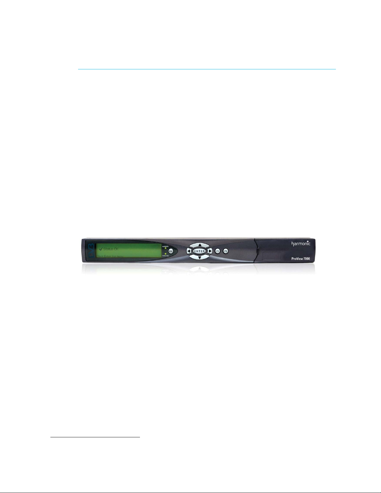
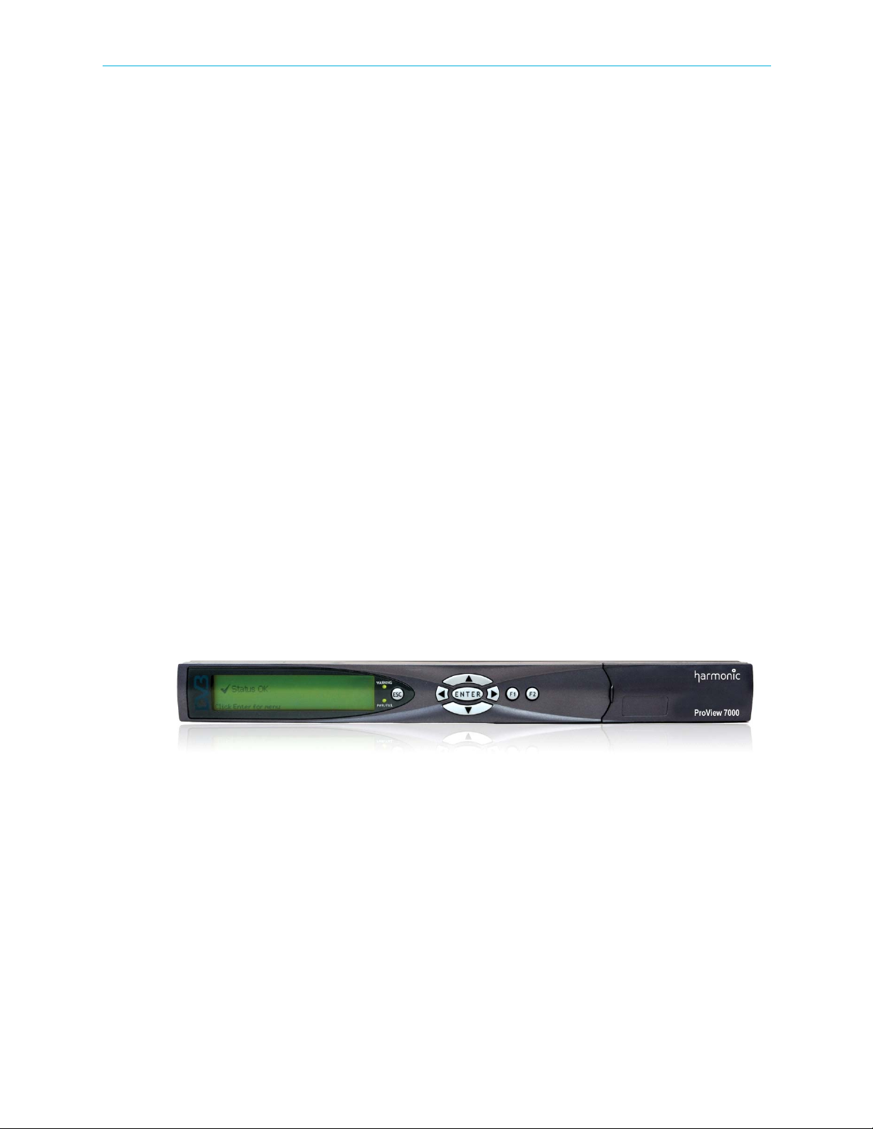
The ProView 7000 platform is housed in a 19" 1RU mount ready enclosure. See Figure 1–1. It
includes fans for right to left air passage for side-to-side heat dissipation, the ProView 7000
may be installed in a rack without spacing between units. This allows increased flexibility for
installation of a large number of units in limited space environments and integration with
additional DVB equipment.
1.4.2 ProView 7000 Front Panel
The front panel of the ProView 7000 platform provides an interface to locally manage and
operate the unit.
Figure 1–1: ProView 7000 Platform General View
The front panel includes, a large LCD display for menus and statuses, four direction buttons,
Enter key an Esc key and two F keys.
an
Two LEDs show the WARNING and PWR/FAIL statuses.
A two slot DVB-CI (DVB Common Interface/Smart Card interface) enables using up to two
Conditional Access Modules (CAMs) for stream descrambling.
See 5.1.1 Main Elements and Structure for a description of the front panel.
© 2011 Harmonic Inc. 16 ProView 7000 v.2.4, Rev. A

Chapter 1 Introduction ProView 7000 Management
1.4.3 ProView 7000 Rear Panel
The rear panel of the ProView 7000 platform includes all of the required professional input
and output connectors. The AC connector and power switch are also located on the rear
panel as well as the GND lug for grounding the unit when installed in a rack. The rear panel is
provided in various configurations as required for different applications. See Appendix B,
Ports and Connectors for a description of the ports and connectors.
1.5 ProView 7000 Management
The ProView 7000 Platform provides a wide range of methods for local and remote
monitoring and management:
Local Front Panel Control
The ProView 7000 front panel provides an easy to use management interface using the large
LCD screen and intuitive controls.
Remote Element Management System (EMS)
The ProView 7000 EMS provides an extensive graphic user interface (GUI) for managing the
device.
Network Management System
The ProView 7000 platform provides monitoring access to Network Management Systems
using its SNMP agent.
ProView 7000 Redundancy
Use NMX management for redundancy to ensure continued service in the event that a device
malfunctions. You can use a single or multiple backup ProView 7000s to ensure continued
service with a single or multiple primary ProView 7000s. This feature is limited to the
management of up to 2 output ports, ASI or SDI.
NOTE: The devices must be identical in hardware configuration, port structure and license.
See the Harmonic NMX Installation/Setup Guide for operating instructions. NMX version 5.6
is required.
© 2011 Harmonic Inc. 17 ProView 7000 v.2.4, Rev. A
The sections are:
■ Safety Precautions
■ Inventory Check
■ Power Supply to the Unit
■ Installing the Unit in a Rack
■ Insertion of the DVB-CI Module (PCMCIA)
■ Electrical Power Connection
■ Connecting the Cables
■ Switching On
2.1 Safety Precautions
To avoid injury and prevent equipment damage, observe the following safety precautions:
■ Do not move or ship equipment unless it is correctly packaged in its original wrapping and
shipping containers.
Chapter 2
Hardware Installation
■ Only Harmonic trained personnel can perform service and maintenance.
■ To prevent lightning damage, ground the unit according to local regulations.
■ Do not permit unqualified personnel to operate the unit.
2.2 Inventory Check
Before installation, ensure that all the equipment and the attached parts are available and
undamaged, according to the following list:
Table 2–1: Inventory
Item Quantity
ProView 7000 Unit 1
Power cable 1
User Manual, ProView 7000 Platform 1 CD
CAUTION: If anything is missing or damaged, do not continue with the installation and report to your
Harmonic support representative.
© 2011 Harmonic Inc. 18 ProView 7000 v.2.4, Rev. A
Chapter 2 Hardware Installation Power Supply to the Unit
2.3 Power Supply to the Unit
To ensure correct and safe operation of the unit, ensure the following:
■ Ensure that a qualified electrician has installed the main power supply in accordance with
power authority regulations. Make sure all powering must be wired with an earth leakage,
according to local regulations.
■ When the unit is rack-mounted, ensure that the rack is correctly grounded.
DANGER: To avoid electrocution, ensure that the rack has been correctly grounded before switching on
the ProView 7000 device. When removing the unit, remove the grounded connection only after the unit is
switched off and unplugged.
2.4 Installing the Unit in a Rack
CAUTION: For rack installation, ensure that a designated 19" rack is fully prepared for installation.
Ensure sufficient space behind the rack for easy access for installation and maintenance. Rack mounting
requires the use of special “L” shape slides, available from Harmonic. The amount of units installed in a
rack is a function of the units’ power consumption and heat dissipation. Address Harmonic support for
calculating the maximum load on the rack.
The following sections detail the installation of a ProView 7000 unit in a 19" rack using the
dedicated mounting slides.
2.4.1 Fitting the Brackets
To f i t t h e b r acke t s:
1. Fit a pair of brackets to both side rails of the rack housing with two flatwasher screws on
each side. Use the two front holes at the sides of the housing to attach the brackets.
(Complementing nuts are already installed on the inner side of the holes, the four screws
required are not included in the supplied kit).
2. Ensure proper grounding of the rack assembly to prevent potential electrical problems.
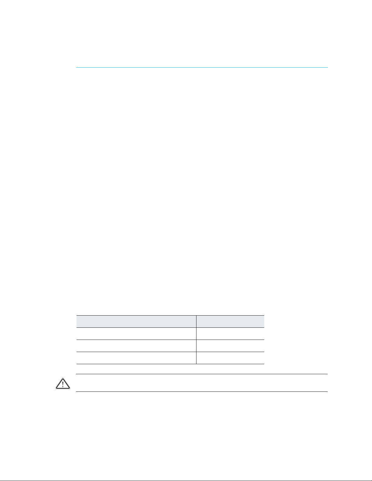
2.4.2 Installing the L Shape Slides
The ProView 7000 uses forced air ventilation, evacuating the air out the left side of the 19”
rack. To ensure smooth airflow, special L shape slides are provided for rack mounting.
To fit the L shape slides:
1. Ensure that the brackets are fastened with appropriate screws to each side of the chassis’
rails.
2. Fit the L shape slides to the fitted brackets and fasten with four screws (not included).
© 2011 Harmonic Inc. 19 ProView 7000 v.2.4, Rev. A

Chapter 2 Hardware Installation Installing the Unit in a Rack
2.4.3 Mounting ProView 7000 units in the 19" Rack
DANGER: To prevent bodily injury when mounting or servicing this unit in a rack, you must take special
precautions to ensure that the system remains stable. The following guidelines are provided to ensure your
safety.
■ This unit should be mounted at the bottom of the rack if it is the only unit in the rack.
■ If the rack will hold a number of units, load the rack from the bottom to the top with the
heaviest component at the bottom of the rack.
■ If the rack is provided with stabilizing devices, install the stabilizers before mounting or
servicing the unit in the rack.
ATTENTION: Pour éviter toute blessure corporelle pendant les opérations de montage ou de
réparation de cette unité en casier, il convient de prendre des précautions spéciales afin de maintenir la
stabilité du système. Les directives ci-dessous sont destinées à assurer la protection du personnel.
■ Si cette unité constitue la seule unité montée en casier, elle doit être placée dans le bas.
■ Si cette unité est montée dans un casier partiellement rempli, charger le casier de bas en
haut en plaçant l’élément le plus lourd dans le bas.
■ Si le casier est équipé de dispositifs stabilisateurs, installer les stabilisateurs avant de
monter ou de réparer l'unité en casier.
WARNUNG: Zur Vermeidung von Körperverletzung beim Anbringen oder Warten dieser Einheit in einem
Gestell müssen sie besondere Vorkehrungen treffen, um sicherzustellen, daß das System stabil bleibt. Die
folgenden Richtlinien sollen zur Gewährleistung Ihrer Sicherheit dienen.
■ Wenn diese Einheit die einzige im Gestell ist, sollte sie unten im Gestell angebracht
werden.
■ Bei Anbringung dieser Einheit in einem zum Teil gefüllten Gestell ist das Gestell von unten
nach oben zu laden, wobei das schwerste Bauteil unten im Gestell anzubringen ist.
■ Wird das Gestell mit Stabilisierungszubehör geliefert, sind zuerst die Stabilisatoren zu
installieren, bevor sie die Einheit im Gestell anbringen oder sie warten.
CAUTION: Ensure that a sufficient amount of airflow enters the ProView 7000 from the left end (from
the front panel point of view) .
Consider if other devices in the rack use airflow in the opposite direction.
Consider that the amount of units installed per rack is a function of power requirements and heat
dissipation. Address Harmonic support for calculating the maximum load on the rack.
To mount the 19"/42U rack with the ProView 7000 units:
1. Mount ProView 7000 units in groups of no more than five units on each pair of brackets.
2. Leave one-unit-space between each group of five units.
© 2011 Harmonic Inc. 20 ProView 7000 v.2.4, Rev. A
Chapter 2 Hardware Installation Insertion of the DVB-CI Module (PCMCIA)
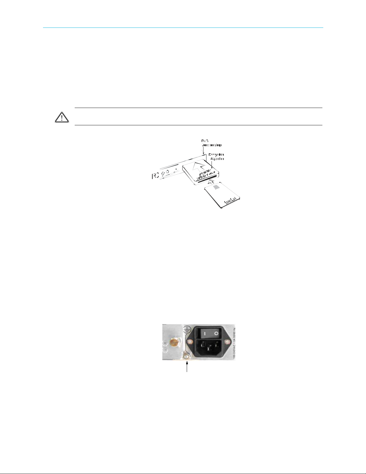
Grounding Jackscrew
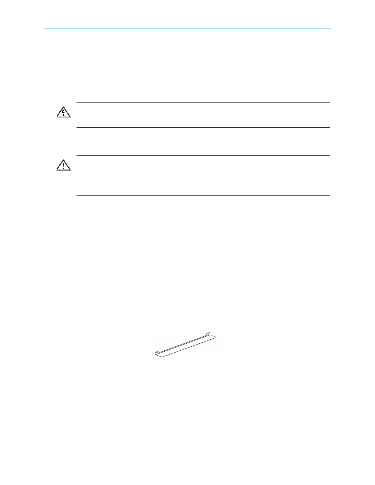
2.5 Insertion of the DVB-CI Module (PCMCIA)
Figure 2–1 illustrates the ProView 7000 with the DVB-CI module (PCMCIA card) and the Smart
Card used to descramble the incoming signal. The ProView 7000 is provided with two PCMCIA
slots for up to two DVB-CI modules.
Insert the PCMCIA card firmly into one of the two slots to ensure contact. Each DVB-CI
module accommodates one Smart Card, inserted with the UP arrow pointing upwards and
forwards.
CAUTION: Do not remove or insert the DVB-CI module or the Smart Card while the ProView 7000 is
powering up or initializing.
Figure 2–1: ProView 7000 with the DVB-CI module and Smart Card
When installed, the card is detected automatically by the ProView 7000 and enabled if the
following conditions are met:
■ The installed card must be EN50221 compatible
■ Services have been selected
■ Using a valid card licensing
2.6 Electrical Power Connection
The ProView 7000 is powered by an AC power supply. Grounding of the ProView 7000 is
provided when the AC power cable is connected to the unit AC connector.
Figure 2–2: AC Connector
When the ProView 7000 is rack-mounted, the device’s grounding jackscrew must be
connected to the rack housing, which must be correctly grounded.
© 2011 Harmonic Inc. 21 ProView 7000 v.2.4, Rev. A
Chapter 2 Hardware Installation Connecting the Cables
DANGER: To avoid electrocution, ensure that the rack has been correctly grounded before switching on
the unit. When removing the unit, remove the grounding connection only after the unit is switched off
and unplugged.
Ground the unit to the grounding jackscrew with cable 18AWG.
CAUTION: This product relies on the building’s electrical installation for short-circuit (overcurrent)
protection. Ensure that a fuse or circuit breaker no larger than 120 VAC, 20 A U.S. (240 VAC, 20 A
international) is used on the phase conductors (all current-carrying conductors).
ATTENTION: Pour ce qui est de la protection contre les courts-circuits (surtension), ce produit dépend
de l’installation électrique du local. Vérifier qu’un fusible ou qu’un disjoncteur de 120 V alt., 20 A U.S.
maximum (240 V alt., 20 A international) est utilisé sur les conducteurs de phase (conducteurs de charge).
WARNUNG: Dieses Produkt ist darauf angewiesen, daß im Gebäude ein Kurzschluß-bzw.
Überstromschutz installiert ist. Stellen sie sicher, daß eine Sicherung oder ein Unterbrecher von nicht mehr
als 240 V Wechselstrom, 20 A (bzw. in den USA 120 V Wechselstrom, 20 A) an den Phasenleitern (allen
stromführenden Leitern) verwendet wird.
2.7 Connecting the Cables
All ProView 7000 connectors are located on the rear panel, see Figure B–1 on page 182.
Connect the following:
■ Input Cables
If you are using DVB-S/S2, connect the satellite cable to the RF IN connector. If you are
using ASI, connect the ASI cables to the connectors marked ASI
■ Management LAN Cable
Connect the management LAN cable to the Management port.
■ Video Output
Connect an output destination to one of the output connectors on the output interface.
■ Video Monitor
Connect a video monitor, for local monitoring of the output, to either the CV MON or the
HDMI port.
IN.
© 2011 Harmonic Inc. 22 ProView 7000 v.2.4, Rev. A

Chapter 2 Hardware Installation Switching On
2.8 Switching On
Before switching the ProView 7000 on, make sure that all cables are correctly connected.
Ensure that the unit is connected to the main power supply and correctly grounded.
❖ Switch the unit on with the rear power switch.
Once the boot process is completed (after 2-3 minutes) the Status OK message displays
on the front panel LCD.
No Service Selected
Status OK
Figure 2–3: Front Panel startup display
© 2011 Harmonic Inc. 23 ProView 7000 v.2.4, Rev. A
Configuration and Monitoring
The sections are:
■ Configuring the IP Parameters
■ The ProView 7000 EMS
■ How to Configure and Monitor the ProView 7000
■ Low Delay Mode
3.1 Configuring the IP Parameters
To configure the IP parameters of a ProView 7000:
1. Press Enter on the keypad.
The root menu displays.
2. Navigate Unit > Management Port > IP Configuration.
Chapter 3
IP Configuration
1 IP Address
2 Subnet Mask
3 Default Gateway
3. Set the IP Address, Subnet Mask and Default Gateway for the port.
4. After any change in the IP configuration, the Apply port changes item is added to the IP
Configuration sub-menu to allow confirmation of the port setup.
5. Select Apply port changes.
6. Select Apply Changes to apply or Drop Changes to abort the configuration.
3.2 The ProView 7000 EMS
The ProView 7000 EMS application provides a GUI for easy management the ProView 7000s.
You can manage up to 10 devices with EMS. Most EMS functions can be performed via the
front panel. You need to have an internet or LAN connection to use EMS.
3.2.1 EMS System Requirements
127.000.000.010
255.255.255.000
000.000.000.000
Minimum platform requirements for EMS:
■ P4 or equivalent processor @ 2 GHz or higher
■ 1 GB of RAM (2 GB highly recommended)
■ Windows XP, Windows Vista, or Windows 7 operating system
© 2011 Harmonic Inc. 24 ProView 7000 v.2.4, Rev. A
Chapter 3 Configuration and Monitoring The ProView 7000 EMS
3.2.2 Installing EMS
The ProView 7000 EMS is stored in the ProView 7000 for easy installation using a web
browser.
To install the ProView 7000 EMS:
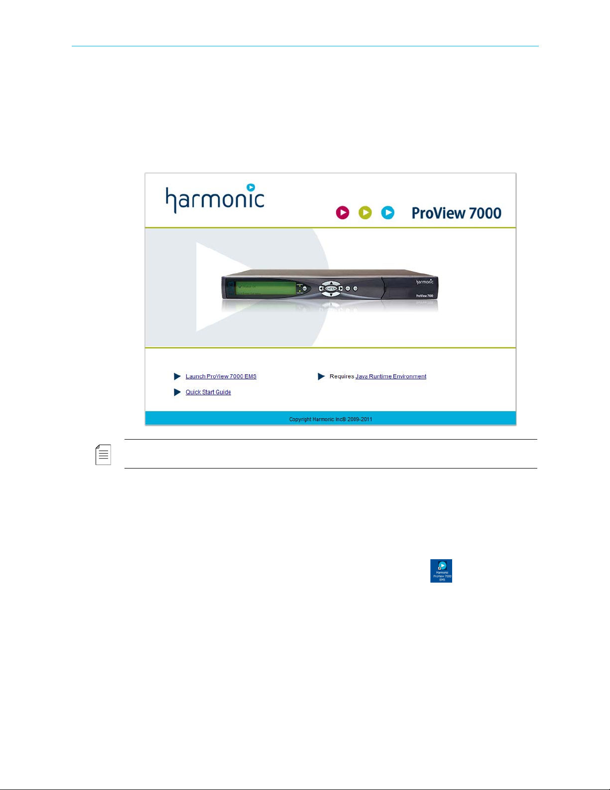
1. Run a web browser and enter the ProView 7000 IP address.
The initial ProView 7000 dialog displays.
NOTE: The EMS application is a Java-based program which requires Java Runtime Environment version
1.6. If needed, install Java Runtime Environment 1.6, using the link provided on the Java Web start page
To check the ProView 7000 EMS Java version:
aRun cmd in Windows.
bEnter
Java -version and press Enter to check which version is currently on your
station. Update if necessary from the Java Web start page.
2. Click
Launch ProView 7000 EMS on the ProView 7000 web page to install the EMS.
The EMS application installs. Shortcuts are added to the desktop and the start
menu.
© 2011 Harmonic Inc. 25 ProView 7000 v.2.4, Rev. A
Chapter 3 Configuration and Monitoring The ProView 7000 EMS
3.2.3 Launching the ProView 7000 EMS
To launch the ProView 7000 EMS:
1. Double-click the Harmonic ProView 7000 EMS launch icon to launch EMS.
The EMS GUI displays.
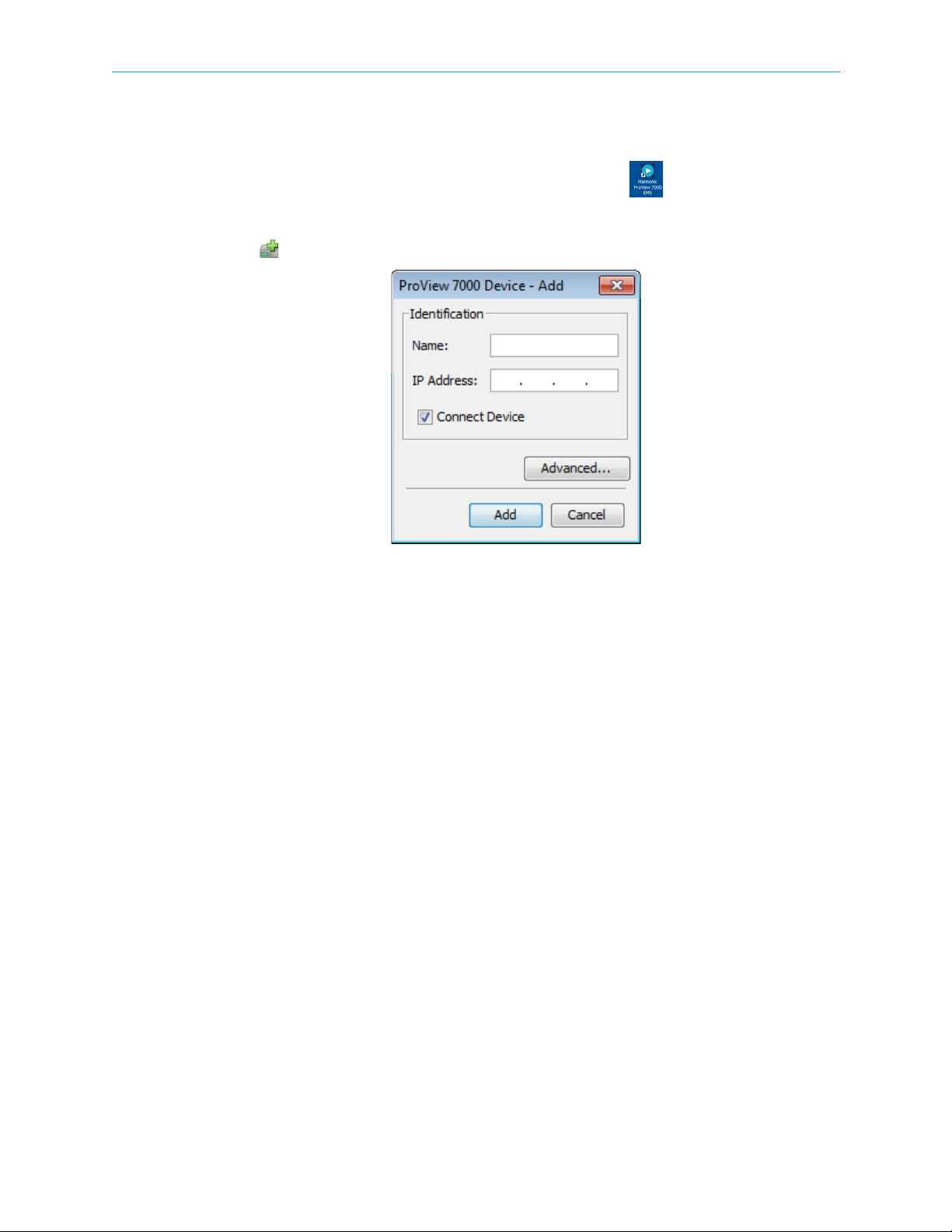
2. Click Add Device on the EMS toolbar.
3. The EMS displays the ProView 7000 Device – Add dialog.
4. Enter a name for the new ProView 7000 device.
5. Enter the IP Address of the new ProView 7000 device.
6. For automatic connection when launching the EMS, mark the Connect Device
checkbox.
7. Click Add.
8. Select the device in the Devices box of the EMS window.
9. Click Device Explorer in the EMS toolbar to display input and output stream trees.
10. If the device fails to connect:
a Right-click the device icon in the Device box and select Ping in the device context
menu.
bClick
c Right-click the device icon in the Device box and select
Ping in the Ping dialog box.
Connect in the device context
menu.
If the ping fails and the device fails to connect, check your network connections and
settings.
dClick
Device Explorer in the EMS toolbar to display input and output stream trees.
See Figure 3–1 for EMS stream management callouts.
© 2011 Harmonic Inc. 26 ProView 7000 v.2.4, Rev. A

Chapter 3 Configuration and Monitoring The ProView 7000 EMS
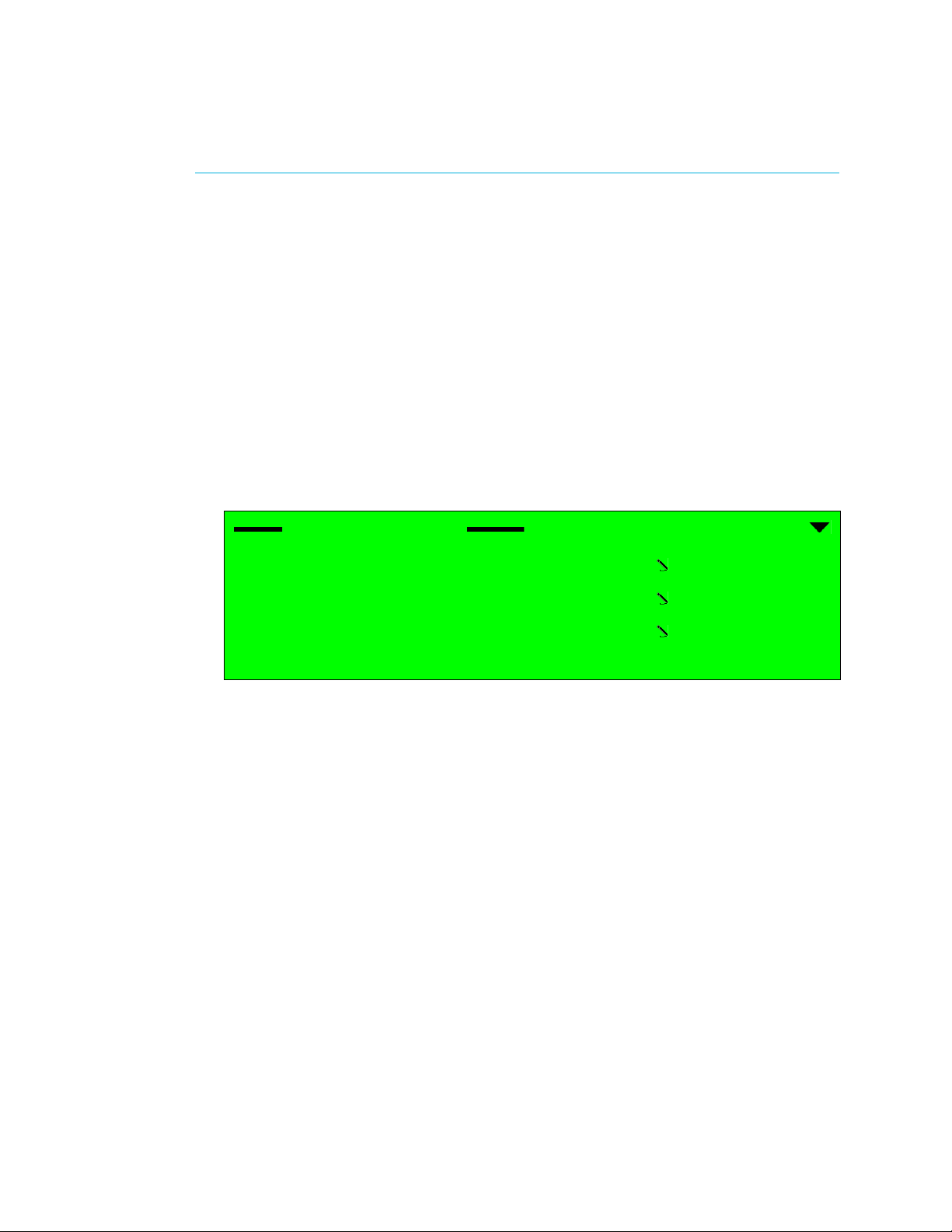
EMS Menu
EMS Toolbar
Box expand/collapse
control
Device stream tab
Alarm report tab
Device box
Physical Input port box Multiplex Input box Multiplex and
decoding Output box
Physical Output port box
Alarm history tab
Figure 3–1: EMS Window
© 2011 Harmonic Inc. 27 ProView 7000 v.2.4, Rev. A

Chapter 3 Configuration and Monitoring How to Configure and Monitor the ProView 7000
3.3 How to Configure and Monitor the ProView 7000
You can configure and monitor the ProView 7000 with either the front panel or over an IP
network using the ProView
■ Configuring the ProView 7000 using the Front Panel
■ Monitoring the ProView 7000 using the Front Panel
■ Configuring the ProView 7000 using EMS
■ Monitoring the ProView 7000 using EMS
3.3.1 Configuring the ProView 7000 using the Front Panel
The ProView 7000 has four logical multiplexes. A license is required for using more than one
multiplex. Some hardware configurations support up to four satellite RF inputs.
The basic order of configuring the ProView 7000 is:
1. Configure a DVB-S/S2 input port.
2. Configure GbE input or output – You cannot receive data over IP with the GbE ports and
output through the GbE ports at the same time, the GbE mode must be changed between
In and Out, the device reboots as part of the process.
3. Descramble selection – The CAM Slot Properties dialog monitors and manages the
selected CAM slot element. It enables you to associate a CAM slot to a multiplex in port
and enable descrambling mode.
4. DVB-S/S2 Input Port association – The DVB-S/S2 In ports in the Physical Input box are
associated by default to multiplex ins in the Multiplex Input box according to their index
numbers (1–4), therefore DVB-S/S2 In Port 1 is associated to DVB Multiplex In 1. You can
associate different ports or additional ports to Multiplex Ins.
7000 EMS.
NOTE: If the input is MPEG then change the table extraction of either a multiplex in or a multiplex out
to PSI Only before you associate the respective multiplex, see 4.5.3.1 Multiplex Input Properties and
4.5.4.1 Multiplex Output Properties.
5. Stream and Program Routing – The ProView 7000 EMS enables drag-and-drop routing of
an input stream to device outputs.
6. Decoder Set-Up – The ProView 7000 EMS supports drag-and-drop definition of an output
decoding channel and configuration of the decoded program properties.
To configure the ProView 7000 via the Front Panel:
1. If the input stream is received from a satellite, navigate
Root > Reception > SAT (no.) > Configuration and configure the receiver parameters
according to your satellite parameters, see
5.2.1.1 Configuration Menu for details.
2. If the input stream is received from IP, perform the following to configure a GbE input
port:
aNavigate Root > Unit > GbE Mode (In/Out).
bSet the GbE mode to
In, see 5.2.8.4 GbE Mode (In/Out) on page 175 for details.
The device reboots.
cNavigate
Root > GbE > GbE Port (1 or 2) > IP Configuration.
d Configure the IP Address and Subnet Mask.
e Select
Apply Port Changes.
© 2011 Harmonic Inc. 28 ProView 7000 v.2.4, Rev. A

Chapter 3 Configuration and Monitoring How to Configure and Monitor the ProView 7000
f Select Apply Changes.
gNavigate
Root > GbE > GbE Port (1 or 2) > Admin Status.
h Set the Admin Status to Up.
iNavigate
Traffic Parameters
Root > GbE > Socket Configuration > Socket In > Socket (no.) >
.
j Configure the IP Address Type, UDP Port and IP Address if you are using Multicast.
kNavigate
Root > GbE > Socket Configuration > Socket In > Socket (no.).
l Configure the Socket De-Jittering Mode, SSM and Socket Admin Status.
3. If the output stream is sent to IP, perform the following to configure a GbE output port:
aNavigate Root > Unit > GbE Mode (In/Out).
bSet the GbE mode to
Out.
The device reboots.
cNavigate
Root > GbE > GbE Port (1 or 2) > IP Configuration.
d Configure the IP Address, Subnet Mask and Default Gateway.
e Select
f Select
gNavigate
Apply Port Changes.
Apply Changes.
Root > GbE > GbE Port (1 or 2) > Admin Status.
h Set the Admin Status to Up.
iNavigate
Root > GbE > Socket Configuration > Socket Out > Socket (no.).
j Configure the Destination IP Address and the Destination UDP Port.
k Set the Socket Status to Up.
4. If you wish to descramble, you must associate the CAM to the multiplex:
aNavigate Root > CAM > CAM (1 or 2) > CAM Association.
b Select a multiplex, TS1, TS2, TS3 or TS4.
The descrambling mode default is Selective, you can change the mode to Full.
5. To access the CAM MMI menu, select CAM MMI.
6. Select a DVB-S/S2 input port:
aNavigate Root > Routing and Descrambling > TS (no.) > Input Selection.
b Select an input port for the received transport stream (Options: SAT (1–4), ASI (1–4)).
7. Select Input Type, (Options: MPEG and DVB). This also sets the respective PSI/SI tables for
the output stream.
NOTE: The default option for stream type is DVB. For ATSC systems, set the stream type to MPEG.
8. To configure the multiplex output:
aNavigate Root > Routing and Descrambling > TS (no.) > Output Selection.
b Select one or more outputs for the received transport stream (Options: ASI (1–2),
Socket (1–4).) The four sockets are virtual and must be associated to a physical GbE
port.
c Select
© 2011 Harmonic Inc. 29 ProView 7000 v.2.4, Rev. A
Enable in each output sub-menu that you select.

Chapter 3 Configuration and Monitoring How to Configure and Monitor the ProView 7000
NOTE: In this mode, stream information is not processed and output bit rate is identical to input bit
rate.
dNavigate Root > Routing and Descrambling > TS (no.) > Activation.
e Select
Enable.
9. To select a program for descrambling:
aNavigate Root > Routing Descrambling > TS (no.) > Descrambling.
A list of all input programs received displays.
Program name, program ID, program type and program scrambling state display.
Descrambling
1 BBC, ID:4301, TV, CAS
2 CNN, ID:4302, TV, CAS
3 IBA 2 ID:4308, AUDIO, FTA
4 MI-TV, ID:8025, TV, FTA
b Select a program for descrambling.
c Select CAM Selection.
d Select CAM 1 or CAM 2 to associate the program to it.
Repeat steps 6 to 9 for each multiplex that you wish to use (1–4).
10. Navigate Root > Decoding > Configuration> Input Selection.
11. Select a multiplex, 1,2, 3 or 4, for input.
12. Set the Service Selection Mode:
aNavigate Root > Decoding > Configuration > Service Selection Mode.
b Select
Program Selection.
13. Navigate Root > Decoding > Configuration> Programs.
Name ID Type
1 ƒ BBC 4301 TV CAS
2 ‚ CNN 4302 TV CAS
3 ‚ IBA 2 4308 AUDIO FTA
Mode
The Programs menu displays a list of programs available on the input transport stream
and enables you to select the program to be decoded.
The screen displays the program name if the input stream provides an SDT table, the
program ID (decimal number), the program type (TV or Radio) and the program mode
(CAS/scrambled or FTA/free to air).
Only one program can be selected (radio button selection).
© 2011 Harmonic Inc. 30 ProView 7000 v.2.4, Rev. A
 Loading...