

Harmonic ProView 2900 Installation Manual

ProView™ 2900 Series of
Integrated Receiver Decoders
Installation Guide
SW Version 1.94
Manual Part No. 101543 – Ver 1.0

Document History
Version Date Details
1.0 June 2009 Software Version 1.94
© Harmonic Inc. All rights reserved.

Disclaimer
Harmonic reserves the right to alter the equipment specifications and descriptions in this publication without prior notice. No part of
this publication shall be deemed to be part of any contract or warranty unless specifically incorporated by reference into such
contract or warranty. The information contained herein is merely descriptive in nature, and does not constitute a binding offer for
sale of the product described herein. Harmonic assumes no responsibility or liability arising from the use of the products described
herein, except as expressly agreed to in writing by Harmonic. The use and purchase of this product do not convey a license under
any patent rights, copyrights, trademark rights, or any intellectual property rights of Harmonic. Nothing hereunder constitutes a
representation or warranty that using any products in the manner described herein will not infringe any patents of third parties.
Trademark Acknowledgments
Harmonic and all Harmonic product names are trademarks of Harmonic Inc. All other trademarks are the property of their respective
owners.
Compliance and Approval
This equipment has been tested and found to comply with the limits for a Class A digital device, pursuant to Part 15, Subpart B of
the Federal Communications Commission (FCC) rules
These limits are designed to provide reasonable protection against harmful interference when the equipment is operated in a
commercial environment.
This equipment generates, uses, and can radiate radio frequency energy. It may cause harmful interference to radio
communications if it is not installed and used in accordance with the instructions in this manual. Operation of this equipment in a
residential area is likely to cause harmful interference. If this occurs, the user will be required to correct the interference at his or her
own expense.
This device complies with Part 15 of the FCC rules. Operation is subject to the following two conditions: (1) this device may not
cause harmful interference, and (2) this device must accept any interference received, including interference that may cause
undesired operation.
Connections between the Harmonic equipment and other equipment must be made in a manner that is consistent with maintaining
compliance with FCC radio frequency emission limits. Modifications to this equipment not expressly approved by Harmonic may void
the authority granted to the user by the FCC to operate this equipment.
WEEE/RoHS Compliance Policy
Harmonic Inc. intends to comply fully with the European Union’s Directive 2002/96/EC as amended by Directive 2003/108/EC, on
Waste Electrical and Electronic Equipment, also known as “WEEE,” and Directive 2002/95/EC, as amended, on the Restriction of
use of Hazardous Substances, also known as “RoHS.”
Harmonic will ensure that product which cannot be reused will be recycled in compliance with the WEEE Directive. To that end,
users are advised that (1) Harmonic equipment is not to be discarded in household or office garbage, (2) Harmonic Inc. will pay the
freight for shipment of equipment to be disposed of if it is returned to Harmonic, (3) customers should call the normal RMA
telephone numbers to arrange for such shipment, and (4) for additional and updated information on this process customers may
consult the Harmonic website: http://harmonicinc.com/ah_weee_recycle.cfm.
Harmonic will ensure that its products will be either reused or recycled in compliance with the WEEE Directive. For the latest
information concerning Harmonic’s WEEE/RoHS Compliance Policy and its Recycling and Take-Back process, please visit our web
site.
© Harmonic Inc. All rights reserved. i

产品中的有毒有害物质或元素的名称及含量表
产品中的有毒有害物质或元素的名称及含量表
产品中的有毒有害物质或元素的名称及含量表产品中的有毒有害物质或元素的名称及含量表
Names and Contents of the Toxic and Hazardous Substances or
Elements in the Products if the Part is Present
该表显示哈雷公司产品中可能含有的有毒有害物质元配件的信息,除了来源于元配件供应商的物料成分资料,
亦来自其它相关的机构与资料。哈雷产品不一定使用这些元配件。
This table shows those components where hazardous substances may be found in Harmonic products based on, among other
things, material content information provided by third party suppliers. These components may or may not be part of the product.
除非特殊注明,哈雷公司产品的环保使用期限
均为20年。该环保使用期限的有效条件为:必须遵循该产品使用手册的规定,对该产品进行使用或存储。
The Environmental Protective Use Period for Harmonic products is 20 years unless displayed otherwise on the product. The EPUP
period is valid only when the products are operated or stored as per the conditions specified in the product manual.
有毒有害物质
部件名称
部件名称 (Part name)
部件名称部件名称
有毒有害物质或元素
有毒有害物质有毒有害物质
铅
(PB)
汞
(Hg) 镉 (Cd)
或元素 (Hazardous Substance)
或元素或元素
六价铬
(CrVI)
多溴联苯
(PBB)
多溴二苯醚
(PBDE)
印刷线路板
(Printed Circuit Assemblies)
机械组件
(Mechanical Subassemblies)
光学组件
(Optical Subassemblies)
电源
(Power Supplies)
缆线 / 线束
(Cables, Harnesses)
屏幕 / 显示器
(Screens, Monitors)
金属零件
(Metal Parts)
塑料/ 发泡材料
(Plastics, Foams)
X O O O O O
X O O O O O
X O O O O O
X O O O O O
X O O O O O
X O O O O O
O O O O O O
O O O O O O
电池
(Batteries)
O: 表示在该部件的所有均质材料中,此类有毒有害物质的含量均小于SJ/T11363-2006标准所规定的限量。
O: Indicates the content of the toxic and hazardous substances at the homogeneous material level of the parts is below the limit
defined in SJ/T11363 2006 standard.
X: 表示至少在该部件的某一均质材料中,此类有毒有害物质的含量超出SJ/T11363-2006标准规定的限量。
X: Indicates that the content of the toxic and hazardous substances in at least one of the homogeneous materials of the parts is
above the limit defined in SJ/T11363 2006 standard.
© Harmonic Inc. All rights reserved. ii
X O O O O O

Standards and Agency Approval
The following tables list regulatory standards and agency approvals:
North America
Standards Agency Approval
EMI: FCC Part 15, Subpart B, ICES-003, Issue 2, Class A FCC
Safety: UL 60950, CSA 60950 cTUV-us Mark
Europe
Standards Agency Approval
EMI/EMC: EN55022, Class A, EN55024 CE
Safety: EN 60950 TUV-GS-Mark, CE
Japan
Standards Agency Approval
EMI: VCCI V-3 / 2000.04 VCCI
Australia and New Zealand
EMI: AS/NZS-3548: 1995 +A1: 1997 +A2: 1997 N/A
Standards Agency Approval
© Harmonic Inc. All rights reserved. iii
Documentation Conventions
This manual uses some special symbols and fonts to call your attention to important information. The
following symbols appear throughout this manual:
DANGER: The Danger symbol calls your attention to information that, if ignored, can cause
physical harm to you.
CAUTION: The Caution symbol calls your attention to information that, if ignored, can
adversely affect the performance of your Harmonic product, or that can make a procedure
needlessly difficult.
LASER DANGER: The Laser symbol and the Danger alert call your attention to information
about the lasers in this product that, if ignored, can cause physical harm to you.
NOTE: The NOTE symbol calls your attention to additional information that you will benefit
from heeding. It may be used to call attention to an especially important piece of information
you need, or it may provide additional information that applies in only some carefully delineated
circumstances.
TIP: The Tip symbol calls your attention to parenthetical information that is not necessary for
performing a given procedure, but which, if followed, might make the procedure or its
subsequent steps easier, smoother, or more efficient.
© Harmonic Inc. All rights reserved. iv

Table of Contents
Chapter 1 Preface........................................................................................................1-1
1.1. Manual Organization ...............................................................................................1-1
Chapter 2 Introduction..............................................................................................2-1
2.1. Operating Environment ..........................................................................................2-1
2.1.1. Highlights and Benefits...........................................................................................2-1
2.1.2. Applications ...............................................................................................................2-2
2.1.3. Management .............................................................................................................2-2
2.1.4. Functionality..............................................................................................................2-3
2.2. ProView 2900 Models ..............................................................................................2-4
2.2.1. ProView 2960 Interfaces and Features ...............................................................2-4
2.2.2. ProView 2961 Interfaces and Features ...............................................................2-5
2.2.3. ProView 2962 Interfaces and Features ...............................................................2-5
2.2.4. ProView 2963 Interfaces and Features ...............................................................2-6
2.2.5. ProView 2980 Interfaces and Features ...............................................................2-7
2.2.6. ProView 2981 Interfaces and Features ...............................................................2-8
2.2.7. ProView 2990 Interfaces and Features ...............................................................2-9
2.2.8. ProView 2991 Interfaces and Features .............................................................2-10
2.2.9. ProView 2992 Interfaces and Features .............................................................2-11
2.3. Mechanical Structure ............................................................................................2-12
2.3.1. Front Panel ..............................................................................................................2-12
2.3.2. Front-Ends...............................................................................................................2-12
2.4. Characteristics and Specifications......................................................................2-14
2.4.1. Transport Stream Interface Options..................................................................2-14
2.4.2. Advanced Processing.............................................................................................2-16
2.4.3. Decoder Outputs ....................................................................................................2-17
2.4.4. Conditional Access .................................................................................................2-18
2.4.5. Control and Monitoring .........................................................................................2-19
2.4.6. Compliance..............................................................................................................2-19
2.4.7. Environmental Conditions ....................................................................................2-20
2.4.8. Physical and Power Specifications......................................................................2-20
Chapter 3 Installation................................................................................................ 3-1
3.1. Safety Precautions...................................................................................................3-1
3.1.1. Restricted Access Area ...........................................................................................3-1
3.1.2. Installation Codes ....................................................................................................3-1
3.1.3. Inventory Check.......................................................................................................3-2
3.2. Installation Instructions .........................................................................................3-2
3.2.1. Power Supply to the Unit .......................................................................................3-2
3.2.2. Installing the Unit in a Rack ..................................................................................3-2
3.2.3. Insertion of the DVB-CI Module (PCMCIA).........................................................3-4
3.3. Electrical Installation...............................................................................................3-5
3.3.1. Cable Connection .....................................................................................................3-5
© Harmonic Inc. All rights reserved. v

3.3.2. Electrical Power Connection...................................................................................3-8
3.4. Initialization and Configuration...........................................................................3-10
3.4.1. Powering Up ............................................................................................................3-10
3.4.2. Tuning ......................................................................................................................3-10
3.4.3. Serviceability Check ..............................................................................................3-10
Chapter 4 ProView 2900 Control Interfaces...................................................... 4-1
4.1. Front Panel Control Interface ................................................................................4-1
4.1.1. Controls and Displays .............................................................................................4-1
4.1.2. ProView 2900 Front Panel Screen Types ............................................................4-2
4.1.3. Front Panel Initialization Sequence .....................................................................4-6
4.2. Web-Based Management Interface......................................................................4-7
4.2.1. Controls and Displays .............................................................................................4-8
4.2.2. Initializing the Web-Based Management ..........................................................4-10
Chapter 5 Operation and Management................................................................ 5-1
5.1. ProView 2900 Root Menu .......................................................................................5-1
5.1.1. ProView 2900 Front Panel Root Menu .................................................................5-1
5.1.2. ProView 2900 Web Manager Main Screen..........................................................5-3
5.2. ProView 2900 Preset Menu ....................................................................................5-3
5.2.1. Recall Preset .............................................................................................................5-5
5.2.2. Save Current Preset ................................................................................................5-6
5.2.3. Rename Preset .........................................................................................................5-8
5.2.4. Delete Preset ............................................................................................................5-9
5.2.5. Delete All Presets (Front Panel Only) ..................................................................5-9
5.3. Configuration ..........................................................................................................5-10
5.4. ProView 2900 Status Menu..................................................................................5-11
5.4.1. Receiver Status ......................................................................................................5-13
5.4.2. Stream Status Menu .............................................................................................5-20
5.4.3. Service Status ........................................................................................................5-22
5.4.4. Video Status Menu.................................................................................................5-22
5.4.5. Audio Status Menu ................................................................................................5-24
5.4.6. Data Status Menu ..................................................................................................5-26
5.4.7. GenLock Status ......................................................................................................5-27
5.4.8. Conditional Access Status Menu .........................................................................5-27
5.4.9. Unit Status Menu ...................................................................................................5-29
Chapter 6 Receiver Configuration..........................................................................6-1
6.1. ProView 2900 Receiver Configuration Menu Tree.............................................6-1
6.2. Satellite Receiver Configuration ...........................................................................6-1
6.2.1. DVB-S Receiver Configuration ..............................................................................6-3
6.2.2. DVB-S2 Receiver Configuration..........................................................................6-10
6.2.3. DVB-DSNG Module ................................................................................................6-20
6.3. IP Receiver Configuration ....................................................................................6-28
6.3.1. MPEGoIP Input 1 ....................................................................................................6-29
6.3.2. General.....................................................................................................................6-32
6.4. DVB-ATM Receiver Configuration.......................................................................6-36
© Harmonic Inc. All rights reserved. vi

6.4.1. Mode .........................................................................................................................6-37
6.4.2. VPI Address.............................................................................................................6-37
6.4.3. VCI Address ............................................................................................................6-37
6.4.4. FEC............................................................................................................................6-37
Chapter 7 Stream Configuration ............................................................................ 7-1
7.1. Stream Configuration Menu Tree .........................................................................7-1
7.1.1. Front Panel Stream Configuration Tree ..............................................................7-1
7.1.2. Web Management Stream Configuration Tree ..................................................7-3
7.2. Stream Input ............................................................................................................7-5
7.2.1. Source ........................................................................................................................7-6
7.2.2. Type ............................................................................................................................7-6
7.2.3. Rate Range................................................................................................................7-7
7.2.4. Input Stream Identifier (ISI) ................................................................................7-7
7.2.5. ASI Mode ...................................................................................................................7-7
7.3. Stream Output..........................................................................................................7-8
7.3.1. ASI Output Source...................................................................................................7-8
7.3.2. IP Output Source .....................................................................................................7-8
7.4. Clock ...........................................................................................................................7-9
7.5. Stream Filtering Configuration............................................................................7-10
7.5.1. Filtering Using the Front Panel Interface..........................................................7-10
7.5.2. Filtering Using the Web-Based Management Interface .................................7-11
7.5.3. Filtering Parameters ..............................................................................................7-12
7.5.4. Select Filtering Services .......................................................................................7-14
7.5.5. Select PIDs ..............................................................................................................7-16
Chapter 8 Service Configuration Menu ................................................................8-1
8.1. Service Configuration Menu Tree .........................................................................8-1
8.2. TV1 Select (and TV2 Select) .................................................................................8-3
8.2.1. PCR..............................................................................................................................8-4
8.2.2. Video...........................................................................................................................8-4
8.2.3. Audio...........................................................................................................................8-5
8.2.4. VBI ..............................................................................................................................8-5
8.3. Stand-Alone Select ..................................................................................................8-6
8.4. Preferred Language .................................................................................................8-6
8.5. PID Select..................................................................................................................8-7
8.6. Mapping Port to Service .........................................................................................8-9
8.7. General Configuration ...........................................................................................8-11
8.7.1. Service Strategy ....................................................................................................8-12
8.7.2. Service CAS Open..................................................................................................8-12
Chapter 9 Video Configuration Menu....................................................................9-1
9.1. Video Configuration Menu Tree ............................................................................9-1
9.2. Video 1 (and Video 2) Configuration Options....................................................9-2
9.2.1. Format........................................................................................................................9-3
9.2.2. Interpolation .............................................................................................................9-4
9.2.3. Monitor Aspect-Ratio...............................................................................................9-4
© Harmonic Inc. All rights reserved. vii

9.2.4. Lip-Sync Mode ..........................................................................................................9-5
9.2.5. STC-PCR Delay .........................................................................................................9-5
9.2.6. Blanking Mode ..........................................................................................................9-6
9.2.7. SDI Embedded Audio ..............................................................................................9-6
9.2.8. Test Mode ..................................................................................................................9-7
9.3. VBI 1 (and VBI 2) Configuration Options ...........................................................9-8
9.3.1. CC (Closed Captioning) Parameter ......................................................................9-9
9.3.2. AMOL (Automatic Measurements Of Line-ups) Parameter ...........................9-10
9.3.3. TVG (TV Guide) Parameter ..................................................................................9-10
9.3.4. VITS (Vertical Interval Test Signals) Parameter.............................................9-11
9.3.5. VITC (Vertical Interval Time Code) Parameter ...............................................9-12
9.3.6. WSS (Wide-Screen Signalling) Parameter .......................................................9-13
9.3.7. VI (Video Index) Parameter ................................................................................9-14
9.3.8. TTX (Teletext-EBU) Parameter ...........................................................................9-14
9.3.9. VPS (Video Program System) Parameter .........................................................9-15
9.3.10. SMC (Sound Mode Concept) Parameter ...........................................................9-15
9.3.11. M422 (Monochrome 4:2:2) Parameter .............................................................9-15
9.4. OSD 1 (and OSD 2) Configuration Options......................................................9-16
9.4.1. Monitor Output .......................................................................................................9-17
9.4.2. Broadcast Output ...................................................................................................9-17
9.4.3. X Position Offset.....................................................................................................9-17
9.4.4. Y Position Offset .....................................................................................................9-17
9.4.5. DVB Subtitle Mode.................................................................................................9-18
9.4.6. TLTX Subtitle Mode................................................................................................9-18
Chapter 10 Audio Configuration Menu............................................................... 10-1
10.1. Audio Configuration Menu Tree ..........................................................................10-1
10.2. Audio Decoder Mode Setup .................................................................................10-3
10.3. AC3 Downmix Mode Setup ..................................................................................10-4
10.4. Audio AC3 Operational Setup..............................................................................10-4
10.5. PassThru Sample Rate ..........................................................................................10-5
10.6. Volume .....................................................................................................................10-5
10.7. Analog Output.........................................................................................................10-5
10.8. Analog Mixer ...........................................................................................................10-5
10.9. Digital Format .........................................................................................................10-6
10.10. Audio Delay .............................................................................................................10-6
10.11. Test Tone.................................................................................................................10-6
Chapter 11 Data Configuration Menu ................................................................. 11-1
11.1. Data Configuration Menu Tree ............................................................................11-1
11.2. Low Speed Data Port ............................................................................................11-2
11.2.1. Baud Rate ................................................................................................................11-3
11.2.2. Layer Filtering.........................................................................................................11-4
11.3. IP-Out-Port Configuration Menu .........................................................................11-4
11.3.1. Operational Mode...................................................................................................11-6
11.3.2. Protocol ....................................................................................................................11-7
11.3.3. IP Address ...............................................................................................................11-7
© Harmonic Inc. All rights reserved. viii

11.3.4. Subnet Mask ...........................................................................................................11-7
11.3.5. Default Gateway ....................................................................................................11-7
11.3.6. Destination IP Address .........................................................................................11-8
11.3.7. UDP Source Port.....................................................................................................11-8
11.3.8. UDP Destination Port.............................................................................................11-8
11.3.9. Number of Packets ................................................................................................11-8
11.4. High Speed Data ....................................................................................................11-9
11.4.1. Tx Clock .................................................................................................................11-10
11.4.2. Tx Direction...........................................................................................................11-10
11.4.3. Layer Filtering.......................................................................................................11-10
Chapter 12 GenLock Configuration Mneu ......................................................... 12-1
12.1. GenLock Configuration Menu Tree .....................................................................12-1
12.2. H Control..................................................................................................................12-2
12.3. V Control..................................................................................................................12-3
12.4. SCH Control.............................................................................................................12-3
Chapter 13 Conditional Access Configuration Menu ..................................... 13-1
13.1. CA Configuration Menu Tree................................................................................13-1
13.2. Common Interface Configuration Menu............................................................13-3
13.2.1. Operation.................................................................................................................13-4
13.2.2. Send MMI (Man-Machine Interface) Command...............................................13-4
13.2.3. Send PIN Code .......................................................................................................13-4
13.3. BISS Mode...............................................................................................................13-5
13.3.1. General.....................................................................................................................13-6
13.3.2. TV1............................................................................................................................13-6
13.4. Embedded Mode.....................................................................................................13-7
13.5. Automatic CAM Reset............................................................................................13-7
Chapter 14 Unit Configuration Menu .................................................................. 14-1
14.1. Unit Configuration Menu Tree .............................................................................14-1
14.2. General Configuration Menu ................................................................................14-3
14.2.1. LCD Contrast (Front Panel Only)........................................................................14-3
14.2.2. Soft Reset ................................................................................................................14-4
14.3. Change Password (Web Manager Only)............................................................14-4
14.4. Control Passwords (Web Manager Only) ..........................................................14-5
14.5. Serial Control Port Configuration........................................................................14-6
14.5.1. HW Interface...........................................................................................................14-6
14.5.2. SW Protocol.............................................................................................................14-7
14.5.3. Baud Rate ................................................................................................................14-7
14.5.4. Address ....................................................................................................................14-7
14.6. Ethernet Management Port..................................................................................14-8
14.6.1. MAC Address ...........................................................................................................14-8
14.6.2. IP Address ...............................................................................................................14-9
14.6.3. Network Mask .........................................................................................................14-9
14.6.4. Default Gateway ....................................................................................................14-9
14.7. Licensing Menu .......................................................................................................14-9
14.7.1. Entering A Serial Key Thru The Front Panel...................................................14-10
© Harmonic Inc. All rights reserved. ix

14.7.2. Entering A Serial Key Thru The Web-Managment ........................................14-10
14.8. Dry Contact Menu ................................................................................................14-11
14.8.1. Delay ......................................................................................................................14-11
14.8.2. Sync Loss...............................................................................................................14-12
14.8.3. HW Failure .............................................................................................................14-12
14.8.4. Invalid PSI .............................................................................................................14-12
14.8.5. TS Buffer Overflow ..............................................................................................14-12
14.8.6. TS Error..................................................................................................................14-13
14.8.7. Continuity Counter ..............................................................................................14-13
14.8.8. CRC Error...............................................................................................................14-13
14.8.9. PRC Discontinuity.................................................................................................14-13
14.8.10. Decoder Buffer Overflow ....................................................................................14-14
14.8.11. Decoder Buffer Underflow..................................................................................14-14
14.8.12. Decoder Stream Error.........................................................................................14-14
14.8.13. Test .........................................................................................................................14-14
14.8.14. Dry Contact Configuration Using the Web-Interface ...................................14-15
14.9. Traps Menu (Web Manager Only).....................................................................14-16
Appendix A DownloadingProView 2900 Software.......................................... A-1
Appendix B IP-Front End Software Upgrade Procedure............................... B-1
Appendix C Aspect Ratio Configuration Process ............................................. C-1
Appendix D ProView 2900 Configuration File .................................................. D-1
Appendix E ProView 2900 Warning Messages ................................................. E-1
© Harmonic Inc. All rights reserved. x

This Installation Manual describes the Harmonic ProView 2900 Series of Integrated Receiver
Decoders (IRDs).
1.1. Manual Organization
This manual contains the following chapters:
Chapter 2, Introduction, introduces the ProView 2900 and describes its features. Provides a
hardware overview' including a description of the back panel ports and connectors and lists
the PROVIEW 2900 characteristics and capabilities.
Chapter 3, Installation, provides rack mounting instructions, electrical installation and basic
instructions for initialization and configuration.
Chapter 4, Control Interfaces, provides general instruction for using the ProView 2900 Front
Panel and Web-Management control interfaces.
Chapter 1
Preface
Chapter 5, Operation and Management, provides specific directives in operating the
ProView 2900 control interfaces.
Chapters 6 and on detail the ProView 2900 Configuration tools provided by the ProView 2900
Front Panel and Web Manager.
Appendix A provides instructions for downloading the ProView 2900 software.
Appendix B describes the procedure for upgrading the IP Front-End software.
Appendix C describes the aspect ration configuration process.
Appendix D describes the ProView 2900 configuration file.
Appendix E lists the warning messages provided by the ProView 2900.
© Harmonic Inc. Manual p/n 101543/Ver 1.0 1-1 ProView 2900 Series/SW Version 1.94

The Harmonic ProView 2900 Series of Integrated Receiver Decoders (IRDs) presents a
professional MPEG-2 DVB and ATSC processing platform, designed to meet even the most
demanding application requirements while maximizing ease of use and flexibility.
This chapter describes:
• The ProView 2900 Series operating environment
• The ProView 2900 Series members' applications and general features.
• The ProView 2900 Series front and rear panel structure.
• The ProView 2900 Series characteristics and capabilities.
2.1. Operating Environment
The ProView 2900 Series concurrently decodes up to two video programs from the transport
stream.
The ProView 2900 Series features the following product lines:
• ProView 296x - Professional single 4:2:0 decoder.
• ProView 298x - Professional single 4:2:0/4:2:2 decoder.
• ProView 299x - Professional dual 4:2:0 decoders.
Chapter 2
Introduction
Housed in a true 1RU slim-line chassis and featuring low power consumption, the
ProView 2900 fully integrates with the Harmonic product platform.
2.1.1. Highlights and Benefits
The ProView 2900 platform’s main features and options include:
• MPEG-2 4:2:0/4:2:2 decoder
• Variety of front-end options including DVB-S, DVB-S2, DVB-DSNG, G.703, MPEG-over-
IP and DS3-ATM
• DVB-S2 professional
• MPEG-over-IP (MPEGoIP) inputs supporting up to 44Mbps (SPTS and MPTS):
Configurable De-Jitter delay
Physical Link Redundancy
Logical Source Redundancy
FEC (Forward Error Correction) ProMPEG CoP3v2
• MPEGoIP output supporting up to 60Mbps
• IP-over-MPEG output up to 60 Mbps (MPE decapsulation)
• 1 or 2 L-Band inputs
• ASI transport stream input and output
• Service and PID Filtering over the ASI and IP outputs (dynamic and static modes)
• DVB common interface (2 slots – 1 active simultaneously)
• SDI, AES/EBU and analogue outputs
© Harmonic Inc. Manual p/n 101543/Ver 1.0 2-1 ProView 2900 Series/SW Version 1.94

Chapter 2: Introduction Operating Environment
• Up to 4 pairs of audio outputs, supporting the following audio schemes;
Musicam, Dolby Digital® AC-3 Pass-Through, Dolby Digital® AC-3 2.0 Down Mixing and
Linear PCM Audio and Dolby-E Pass-Through (up to 3 outputs)
• Embedded audio in SDI and re-insertion of VBI
• VBI re-insertion in composite and SDI
• Genlock for high-end accurate frame synchronization and phase compensation.
• Redundancy support, 2 GPI Dry Contact relays with separate control
• OSD (On-Screen Display) subtitling
• Various of management interfaces: Graphical front-panel, user-friendly Web-Interface,
command-line-interface (CLI) and SNMP
• SW permission mechanism enables future upgrade
• 50 different user defined setups
2.1.2. Applications
The ProView 2900 processing platform is a technologically advanced choice for a wide range
of applications. Some typical uses include:
• Digital turnaround
• CATV IP head-end receiver/decoder
• CATV IP distribution edge decoder
• Satellite distribution
• Telco distribution
• DSNG
• Syndication
Harmonic offers this series of professional IRDs in a wide range of standard configurations,
with the flexibility to select specific interfaces and applicable required features.
2.1.3. Management
The ProView 2900 provides a wide range of local and remote management options.
Local management methods:
• Front Panel Control - The ProView 2900 front panel provides an easy to use graphical
display with a large LCD screen and intuitive control.
• PC Terminal Control - The ProView 2900 supports PC terminal control from a standard
PC terminal (over RS-232 or RS-485). The terminal provides access to control and
monitor functionalities that are not available when using any ProView 2900 front panel
feature.
Remote management methods:
• NMS - The Network Management System enables management of the ProView 2900
through the transmission link. The NMS provides a menu and dialog-driven interface from
which control, modification, and upgrade operations can be performed on the
ProView 2900.
• Web-Based Management - ProView 2900 supports web-based management. Managing
ProView 2900 parameters using web-based control is as easy as point-and-click.
© Harmonic Inc. Manual p/n 101543/Ver 1.0 2-2 ProView 2900 Series/SW Version 1.94
Chapter 2: Introduction Operating Environment
• Telnet - The ProView 2900 supports remote control throughout the Internet. The
ProView 2900 can be controlled and configured from a standard PC terminal (over
Ethernet).
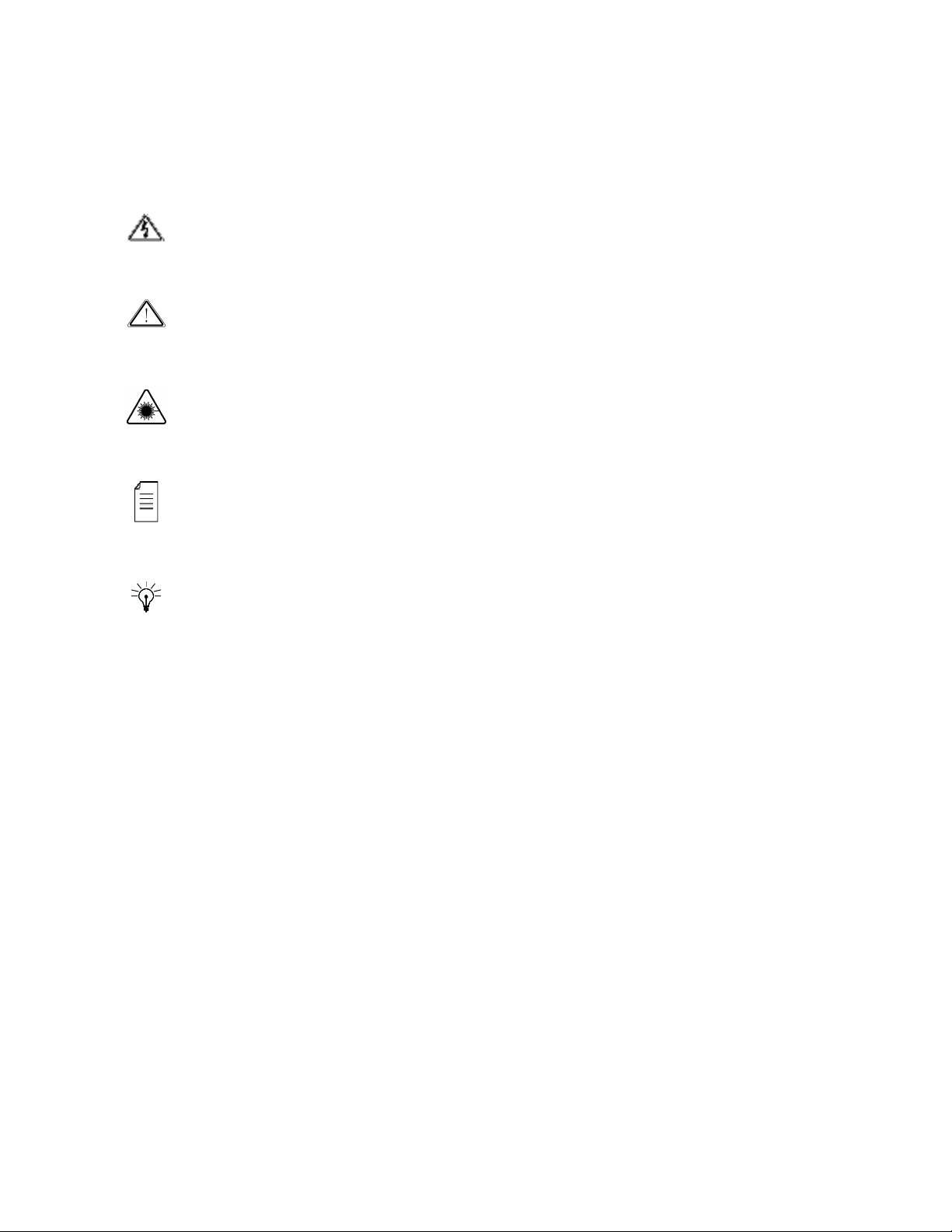
2.1.4. Functionality
The TS Router block receives input streams from an available source, for example: L-Band,
MPEG-over-IP IN and ASI IN. Then the block routes the selected input to the Master and
Slave decoders. Each decoder decodes one program from the input stream, routed by the TS
router block, and provides decoded digital audio and video streams. These streams are
provided to the Video Router block that routes them to the relevant outputs as well as to the
analog video output. The Analog Video Output receives a digital video, converts the digital
video into analog video, and outputs the analog video. The analog and digital audio output
component outputs the digital and analog audio.
Figure 2-1: Signal Path in the ProView 2900 – Functionality Block Diagram
© Harmonic Inc. Manual p/n 101543/Ver 1.0 2-3 ProView 2900 Series/SW Version 1.94
Chapter 2: Introduction ProView 2900 Models
2.2. ProView 2900 Models
Each ProView 2900 model is provided with a basic feature package. In order to suit specific
requirements, additional license-permitted features are available. The following paragraphs
specifies the basic and optional features available for each model.
In order to enable optional features perform one of the following:
• Upon unit ordering - order the relevant features. The unit will be provided with the
ordered features enabled.
• After unit ordering - order the relevant features. In this case, a 16 character key issued
by Harmonic video networks will be provided. The key must be entered to the unit thru
the front-panel or the web-interface. For details see section 14.7
NOTE
When RS-232 low-speed-data and/or RS-422 high-speed-data are enabled the PID
Filtering is unavailable.
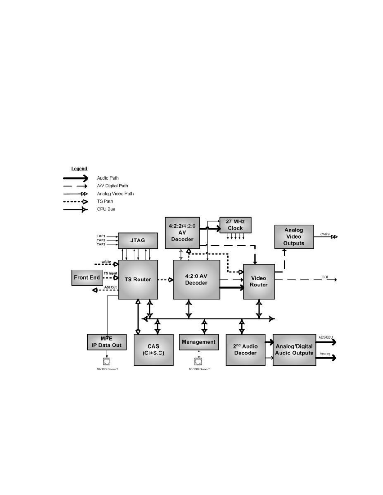
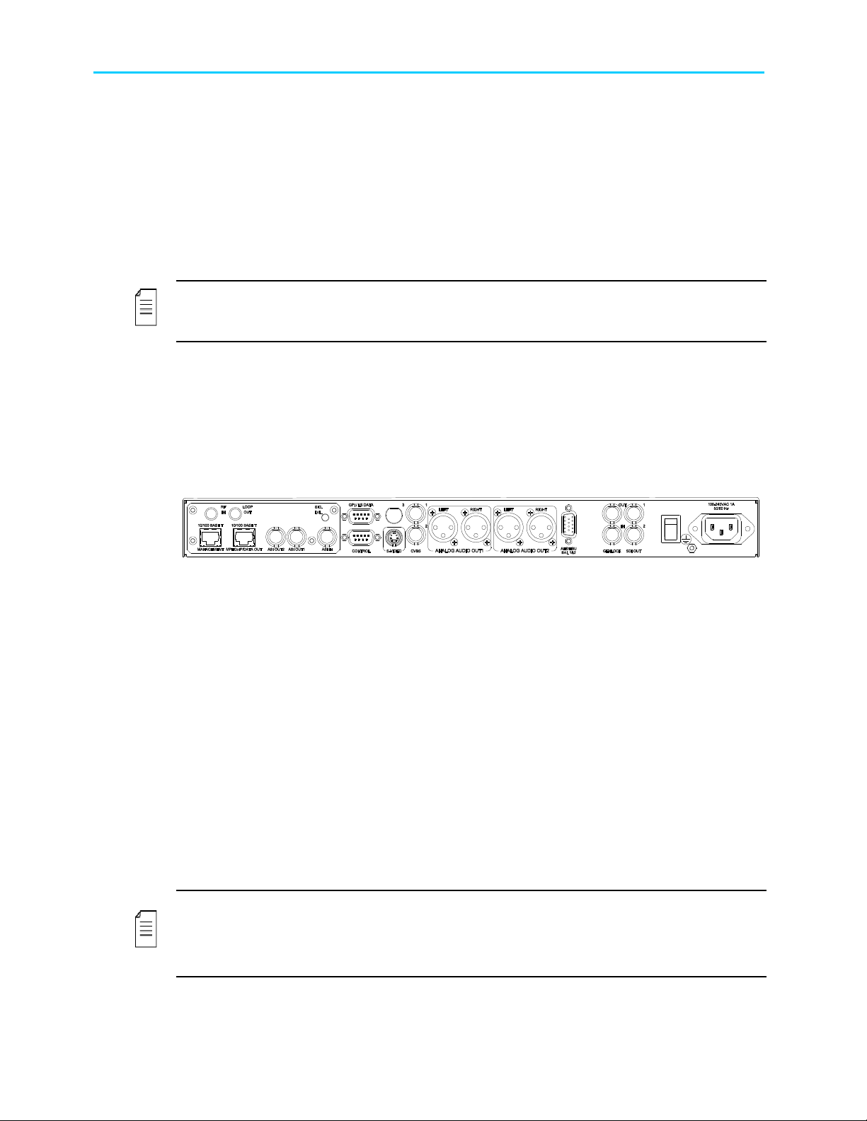
2.2.1. ProView 2960 Interfaces and Features
The ProView 2960 is a single 4:2:0 Decoder IRD. The ProView 296x devices consist of two
composite video interfaces. The CVBS #1 connector is used for broadcasting quality video
and the CVBS #2 connector is used for monitoring.
Figure 2-2 illustrates the ProView 2960 rear panel. The ProView 2960 basic features and
software-licensed features are also detailed.
Figure 2-2: ProView 2960 Rear Panel (Standard)
Basic Features
• 1 composite video - Broadcast quality
(upper connector)
• 1 composite video - Monitoring quality
(lower connector)
• 2 active analog – audio - stereo
balanced interfaces
• GPI
Software-Licensed Features
• Dolby digital (AC-3) LT/RT downmixing
• RS-232 low speed data output
• RS-422 high speed data output
• DVB-S2 Advance Modulation (optional)
NOTES
The ProView 2960 does not support the Decoder Only configuration.
The Russian SECAM D/K (composite video only) is available only through Special orders.
© Harmonic Inc. Manual p/n 101543/Ver 1.0 2-4 ProView 2900 Series/SW Version 1.94
Chapter 2: Introduction ProView 2900 Models
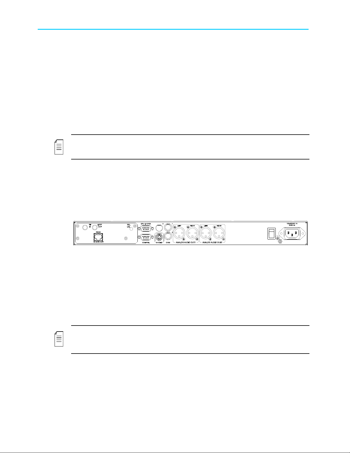
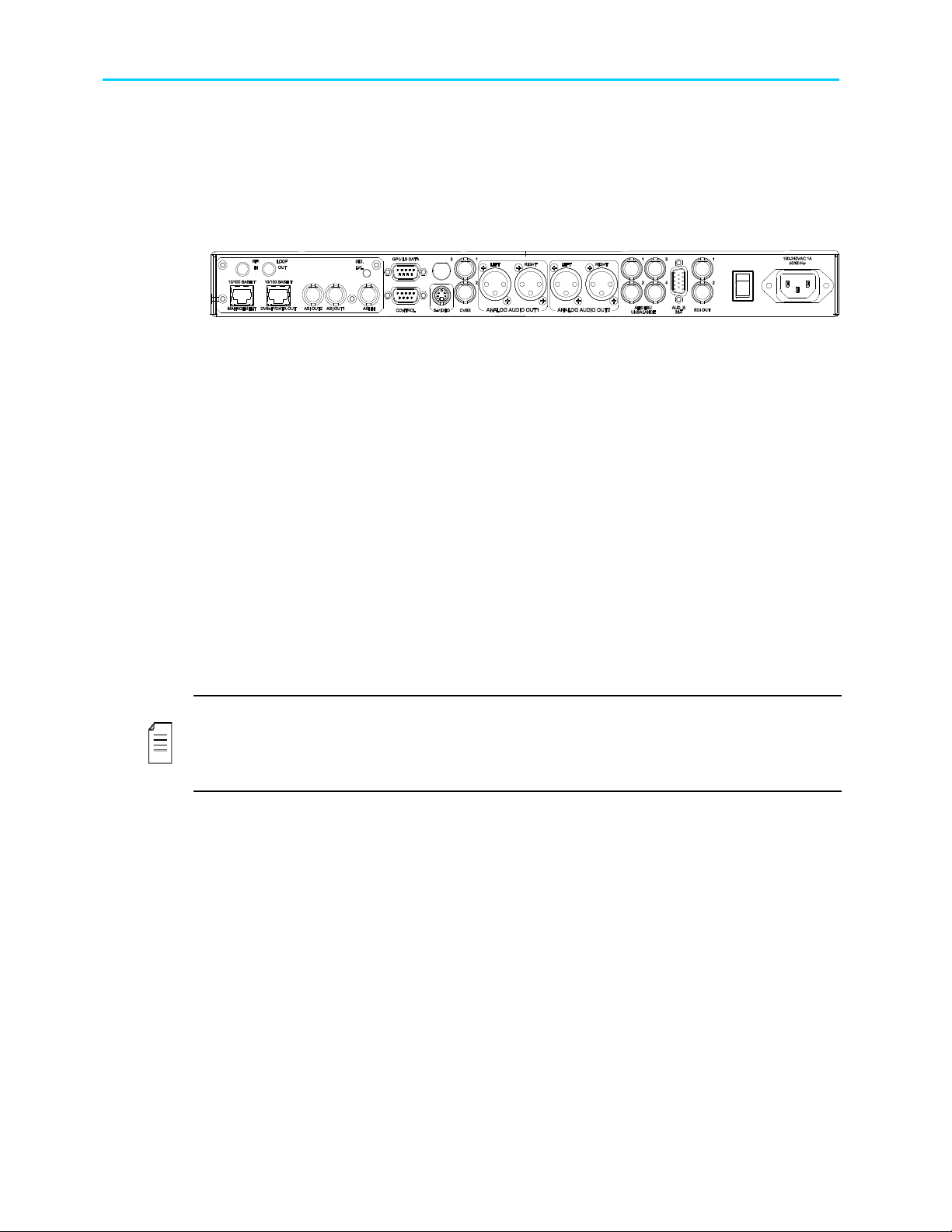
2.2.2. ProView 2961 Interfaces and Features
The ProView 2961 is a single 4:2:0 decoder DVB RECEIVER/DECODER. The ProView 296x
family consists of two composite video interfaces. The CVBS #1 connector is used for
broadcast quality video and the CVBS #2 connector is used for monitoring.
Figure 2-3 illustrates the ProView 2961 rear panel. The ProView 2961 basic features and
software-licensed features are also detailed.
Figure 2-3: ProView 2961 Rear Panel
Basic Features
• 1 composite video - Broadcast
quality (upper connector)
• 1 composite video - Monitoring
quality (lower connector)
• 2 active analog – audio - stereo
balanced interfaces
• SNMP management (10/100 Base-T)
• Web based management
(10/100Base-T)
• GPI
Software-Licensed Features
• ASI Input
• Dual (identical) ASI outputs
• MPEG-over-IP output or IP data output (MPE de-
capsulation)
• Dolby Digital (AC-3) LT/RT downmixing
• Pro MPEG FEC
• IP Dual input (link and source redundancy
• PID and service filtering
• RS-232 low speed data output
• DVB-S2 Advance Modulation (optional)
NOTES
In the case of power failure or system shutdown, ASI OUT 1 output will become ASI loopthrough. Use ASI OUT 1 output for cascading a chain of ProView 2900.
The Russian SECAM D/K (composite video only) is available only through special orders.
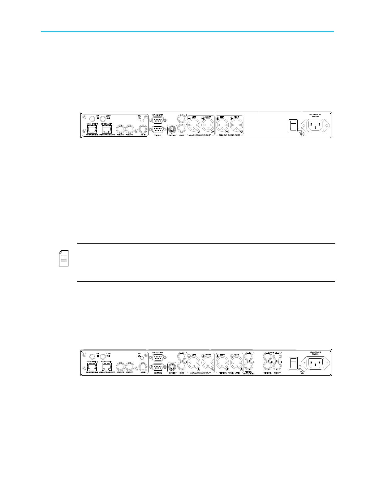
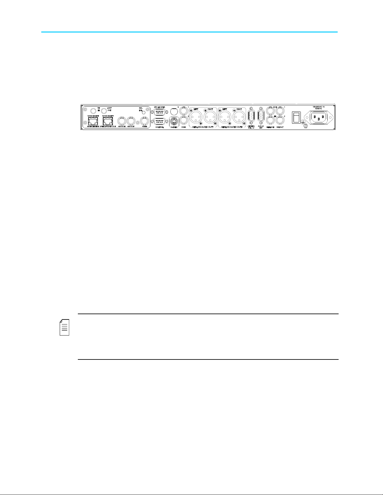
2.2.3. ProView 2962 Interfaces and Features
The ProView 2962 is a single 4:2:0 decoder. The entire ProView 296x family consists of two
composite video interfaces. The CVBS #1 connector is used for broadcast quality video and
the CVBS #2 connector can is for monitoring.
Figure 2-4 illustrates the ProView 2962 rear panel. The ProView 2962 basic features and
software-licensed features are also detailed.
Figure 2-4: ProView 2962 Rear Panel
Basic Features
• 1 composite video - Broadcast quality (upper
connector)
• 1 composite video - Monitoring quality (lower
connector)
• 2 SDI interfaces
© Harmonic Inc. Manual p/n 101543/Ver 1.0 2-5 ProView 2900 Series/SW Version 1.94
Software-Licensed Features
• ASI Input
• Dual (identical) ASI outputs
• MPEG-over-IP output or IP data output
(MPE de-capsulation)
• Genlock input and loop-through output
Chapter 2: Introduction ProView 2900 Models
• Embedded VBI and up to 2 stereo channels in
SDI
• 2 activated analog-audio-stereo balanced
interfaces
• 2 activated AES/EBU-SPDIF audio-unbalanced
interfaces
• SNMP management (10/100 Base-T)
• Web-based management (10/100 Base-T)
• GPI
• Front panel A/V monitoring connectors
• Dolby Digital (AC-3) LT/RT downmixing.
• Pro MPEG FEC
• PID and service filtering
• RS-232 low speed data output
• DVB-S2 Advance Modulation (optional)
NOTE
In the case of power failure or system shutdown, ASI OUT 1 output will become ASI loopthrough. Use ASI OUT 1 output for cascading a chain of ProView 2900.
2.2.4. ProView 2963 Interfaces and Features
The ProView 2963 is a single 4:2:0 decoder. The entire ProView 296X family consists of two
composite video interfaces. The CVBS #1 connector is used for broadcast quality video and
the CVBS #2 connector is used for monitoring.
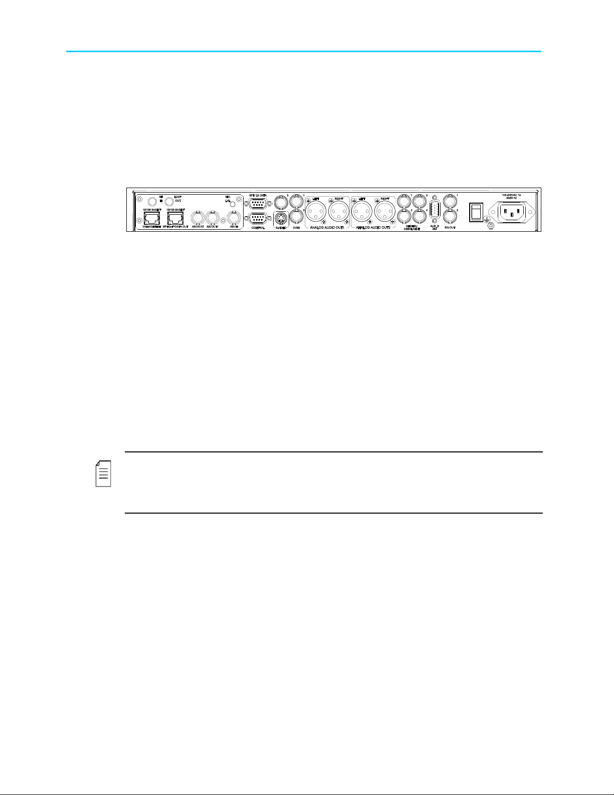
Figure 2-5 illustrates the ProView 2963 rear panel. The ProView 2963 basic features and
software-licensed features are described below.
Figure 2-5: ProView 2963 Rear Panel
Basic Features
• 1 composite video - Broadcast quality (upper
connector)
• 1 composite video - Monitoring quality (lower
connector)
• 2 SDI interfaces
• Embedded VBI and up to 2 stereo channels in
SDI
• 2 active analog-audio-stereo balanced
interfaces
• 2 active AES/EBU-SPDIF audio-balanced
interfaces
• SNMP management (10/100 Base-T)
• Web-based management (10/100 Base-T)
• GPI
• Front panel A/V monitoring connectors
Software-Licensed Features
• ASI input
• Dual (identical) ASI output
• MPEG-over-IP output or IP data
output (MPE de-capsulation)
• Genlock input and loop-through output
• Dolby Digital (AC-3) LT/RT
downmixing
• Pro MPEG FEC
• IP Dual input (link and source
redundancy
• PID and service filtering
• RS-232 low speed data output
• DVB-S2 Advance Modulation
(optional)
NOTES
This model requires a breakout cable to connect to the AES/EBU interfaces.
In case of power failure or system shutdown, ASI OUT 1 output will become ASI loop-through.
Use ASI OUT 1 output for cascading a chain of ProView 2900
© Harmonic Inc. Manual p/n 101543/Ver 1.0 2-6 ProView 2900 Series/SW Version 1.94
Chapter 2: Introduction ProView 2900 Models
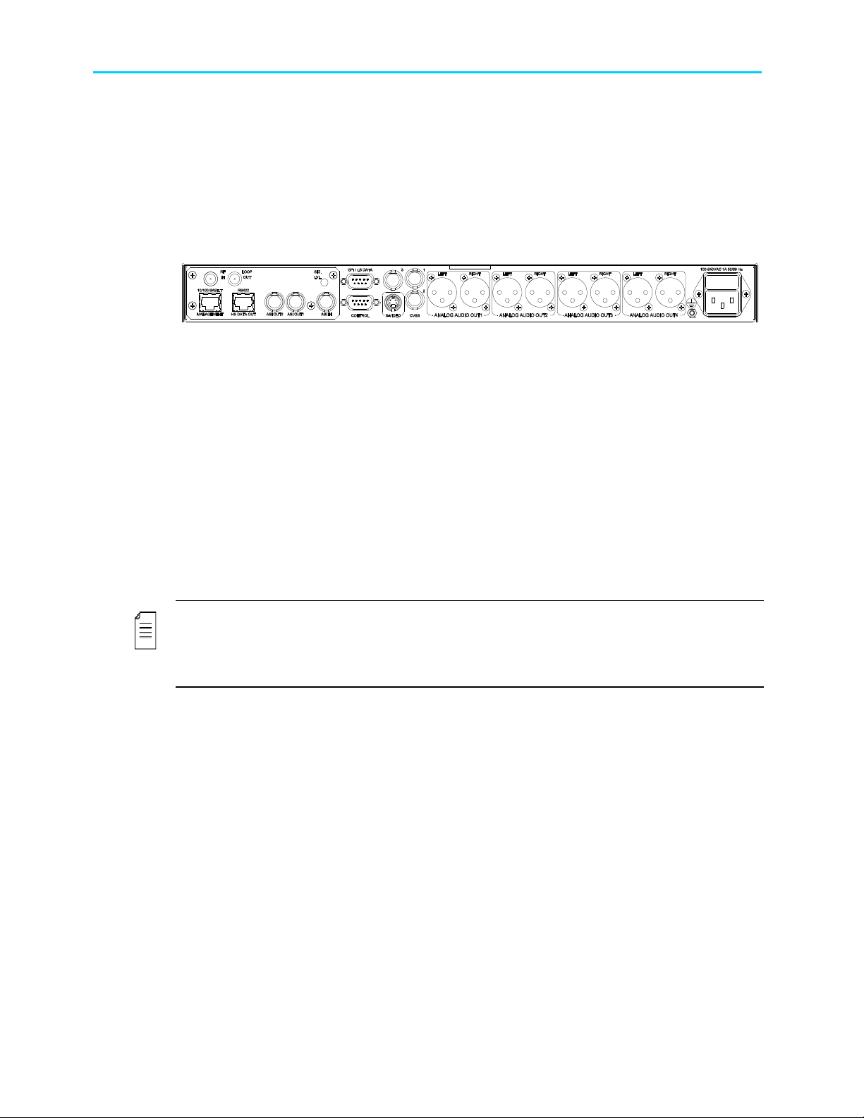
2.2.5. ProView 2980 Interfaces and Features
The ProView 2980 is a single 4:2:0/4:2:2 decoder. The ProView 298x family consists of
two composite video interfaces. Both CVBS #1 and CVBS #2 connectors are for broadcast
quality video. Figure 2-6 illustrates the ProView 2980 rear panel. The ProView 2980 basic
and software-licensed features are also detailed.
Figure 2-6: ProView 2980 Rear Panel
Basic Features
• 2 composite video interfaces – Broadcast
quality
• 2 SDI interfaces
• Embedded VBI and up to 4 stereo channels
in SDI
• Decoding 4:2:2 PP@ML (1.5–50 Mbps)
• 2 out of 4 active analog-audio-stereo
balanced interfaces
• 2 out of 4 active AES/EBU-SPDIF audio
unbalanced interfaces
• 1ST and 2ND active AES/EBU-SPDIF
• SNMP management (10/100 Base-T)
• Web-based management (10/100 Base-T)
• GPI
• Front panel A/V monitoring connectors
Software-Licensed Features
• ASI input
• Dual (identical) ASI output
• MPEG-over-IP output or IP data output
(MPE de-capsulation)
• 3RD Active analog stereo pair
• 4TH Active analog stereo pair
• 3RD Active AES/EBU-SPDIF
• 4TH Active AES/EBU-SPDIF
• Dolby Digital (AC-3) LT/RT downmixing
• Linear PCM (SMPTE 302M 2000), Dolby-E
pass-through
• Pro MPEG FEC
• IP Dual input (link and source redundancy
• PID and service filtering
• RS-232 low speed data output
• DVB-S2 Advance Modulation (optional)
NOTES
This model requires a breakout cable to connect to the 3rd and 4th analog stereo pairs.
In the case of power failure or system shutdown, ASI OUT 1 output will become ASI loop-
through. Use ASI OUT 1 output for cascading a chain of ProView 2900.
© Harmonic Inc. Manual p/n 101543/Ver 1.0 2-7 ProView 2900 Series/SW Version 1.94
Chapter 2: Introduction ProView 2900 Models
2.2.6. ProView 2981 Interfaces and Features
The ProView 2981 is a single 4:2:2 decoder. The ProView 298x family consists of two
composite video interfaces. Both CVBS interfaces are for service broadcast video quality.
Figure 2-7 illustrates the ProView 2981 rear panel. The ProView 2981 basic and software-
licensed features are also detailed.
Figure 2-7: ProView 2981 Rear Panel
Basic Features
• 2 composite video interfaces – Broadcast quality
• 2 SDI interfaces
• Embedded VBI and up to 4 stereo channels in
SDI
• Decoding 4:2:2 PP@ML (1.5–50 Mbps)
• 2 out of 4 active analog-audio-stereo balanced
interfaces
• 2 out of 4 active AES/EBU-SPDIF audio-balanced
interfaces
• Genlock input and loop-through output
• SNMP management (10/100 Base-T)
• Web-based management (10/100 Base-T)
• GPI
• Front panel A/V monitoring connectors
Software-Licensed Features
• ASI input
• Dual (identical) ASI output
• MPEG-over-IP output or IP data output
(MPE de-capsulation)
• 3rd Active analog stereo pair
• 4th Active analog stereo pair
• 3rd Active AES/EBU-SPDIF
• 4th Active AES/EBU-SPDIF
• Dolby Digital (AC-3) LT/RT
downmixing
• Linear PCM (SMPTE 302M 2000),
Dolby-E pass-through
• Genlock input and loop-through output
• Dolby Digital (AC-3) LT/RT
downmixing.
• Pro MPEG FEC
• PID and service filtering
• RS-232 low speed data output
• DVB-S2 Advance Modulation
(optional)
NOTES
This model requires a breakout cable to connect to the AES/EBU interfaces and to connect to
the 3rd and 4th analog stereo pairs.
In the case of power failure or system shutdown, ASI OUT 1 output will become ASI loopthrough. Use ASI OUT 1 output for cascading a chain of ProView 2900.
© Harmonic Inc. Manual p/n 101543/Ver 1.0 2-8 ProView 2900 Series/SW Version 1.94
Chapter 2: Introduction ProView 2900 Models
2.2.7. ProView 2990 Interfaces and Features
The ProView 2990 is a dual 4:2:0 decoder. The ProView 299x family consists of three
composite video interfaces. The CVBS #1 connector is for the broadcast quality video of
decoder #1. The CVBS #2 is used for monitoring. The CVBS #3 connector is for the
broadcast quality video of decoder #2.
Figure 2-8 illustrates the ProView 2990 rear panel. The ProView 2990 basic and softwarelicensed features are also detailed.
Figure 2-8: ProView 2990 Rear Panel
Basic Features
• 1 composite video for program 1- Broadcast
quality (upper-right connector)
• 1 composite video for program 2 - Broadcast
quality (upper-left connector)
• 1 composite video for program 1- Monitoring
quality (lower connector)
• 4 active analog-audio-stereo balanced
interfaces
• SNMP management (10/100 Base-T)
• Web-based management (10/100 Base-T)
• RS-422 high speed data output
• GPI
Software Licensed Features
• ASI input
• Dual (identical) ASI output
• Dolby Digital (AC-3) LT/RT
downmixing
• RS-232 low speed data output
• RS-422 high speed data output
• DVB-S2 Advance Modulation
(optional)
NOTE
In the case of power failure or system shutdown, ASI OUT 1 output will become ASI loopthrough. Use ASI OUT 1 output for cascading a chain of ProView 2900.
The Russian SECAM D/K (composite video only) is available only through special orders.
© Harmonic Inc. Manual p/n 101543/Ver 1.0 2-9 ProView 2900 Series/SW Version 1.94
Chapter 2: Introduction ProView 2900 Models
2.2.8. ProView 2991 Interfaces and Features
The ProView 2991 is a dual 4:2:0 decoder. The ProView 299x family consists of three composite
video interfaces. The CVBS #1 connector is for the broadcast quality video of decoder #1.
The CVBS #2 is used for monitoring. The CVBS #3 connector is for broadcast quality video of
decoder #2.
Figure 1-13 illustrates the ProView 2991 rear panel. The ProView 2991 basic features and
software-licensed features are also detailed.
Figure 2-9: ProView 2991 Rear Panel
Basic Features
• 3 composite video interfaces (2 for broadcast, 1
for monitoring)
• 2 SDI interfaces
• Embedded VBI and up to 4 stereo channels in
SDI
• 4 active analog-audio-stereo balanced
interfaces
• 4 active AES/EBU-SPDIF audio unbalanced
interface
• SNMP management (10/100 Base-T)
• Web-based management (10/100 Base-T)
• GPI
Software-Licensed Features
• ASI input
• Dual (identical) ASI output
• MPEG-over-IP output or IP data
output (MPE de-capsulation)
• Dolby Digital (AC-3) LT/RT
downmixing
• Linear PCM (SMPTE 302M 2000),
Dolby-E pass-through.
• Pro MPEG FEC
• PID and service filtering
• RS-232 low speed data output
• DVB-S2 Advance Modulation
(optional)
NOTES
This model requires a breakout cable to connect to the 3rd and 4th analog stereo pairs.
In case of power failure or system shutdown, ASI OUT 1 output will become ASI loop-through.
Use ASI OUT 1 output for cascading a chain of ProView 2900.
© Harmonic Inc. Manual p/n 101543/Ver 1.0 2-10 ProView 2900 Series/SW Version 1.94

Chapter 2: Introduction ProView 2900 Models
2.2.9. ProView 2992 Interfaces and Features
The ProView 2992 is a dual 4:2:0 decoder. The ProView 299x family consists of three
composite video interfaces. The CVBS #1 is for service broadcast video quality. The CVBS
#2 is for service monitoring and OSD video quality. The CVBS #3 is for additional service
broadcast video quality.
Figure 2-10 illustrates the ProView 2992 rear panel. The ProView 2992 basic features and
software-licensed features are also detailed.
Figure 2-10: ProView 2992 Rear Panel
Basic Features
• 3 composite video interfaces (2 for broadcast, 1
for monitoring)
• 2 SDI interfaces
• Embedded VBI and up to 4 stereo channels in
SDI
• 4 active analog-audio-stereo balanced
interfaces
• 4 active AES/EBU-SPDIF audio balanced
interfaces
• SNMP management (10/100 Bas-T)
• Web-based management (10/100 Base-T)
• GPI
Software-Licensed Features
• ASI input
• Dual (identical) ASI output
• MPEG-over-IP output or IP data output
(MPE de-capsulation)
• Genlock input and loop-through output
• Dolby Digital (AC-3) LT/RT downmixing
• Linear PCM (SMPTE 302M 2000),
Dolby-E pass-through
• Pro MPEG FEC
• PID and service filtering
• RS-232 low speed data output
• DVB-S2 Advance Modulation (optional)
NOTES
This model requires a breakout cable to connect to the AES/EBU interfaces and to connect to
the 3rd and 4th analog stereo pairs.
In the case of power failure or system shutdown, ASI OUT 1 output will become ASI loopthrough. Use ASI OUT 1 output for cascading a chain of ProView 2900
© Harmonic Inc. Manual p/n 101543/Ver 1.0 2-11 ProView 2900 Series/SW Version 1.94
Chapter 2: Introduction Mechanical Structure
2.3. Mechanical Structure
The ProView 2900 is housed in a rugged industrial enclosure, 1RU by 19" (rack mount).
Figure 2-11: ProView 2900 Unit – General View
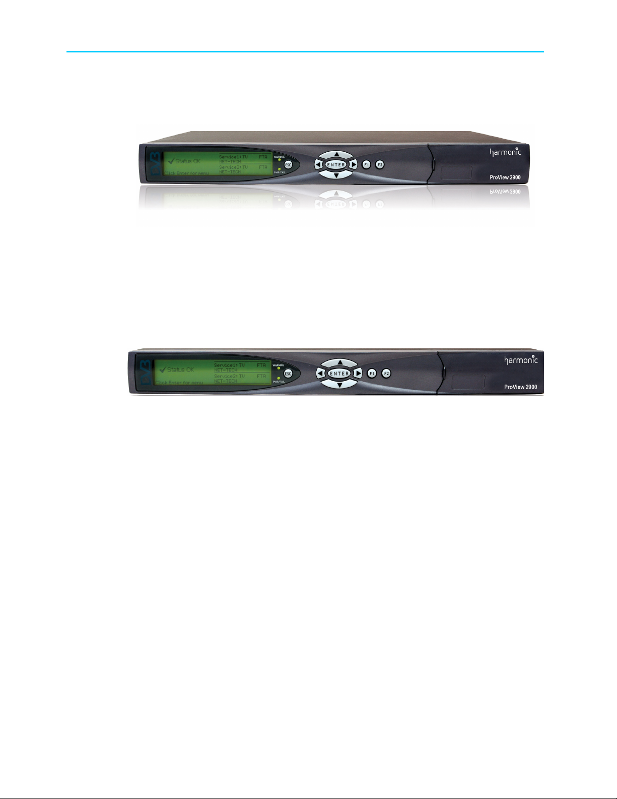
2.3.1. Front Panel
The front panel allows control using a four-way touch pad, [Enter] key, [Esc] key, and two
programmable [F1]/[F2] keys. Operational commands and parameters are displayed on a
graphical LCD. The four-way touch pad allows parameter modification and scrolling through
the embedded VBI menus. Two LEDs show the WARNING and PWR/FAIL status (see Figure
2-12).
2.3.2. Front-Ends
ProView 2900 supports the following interfaces:
DVB-S Single L-Band input
DVB-S Dual L-Band input
DVB-DSNG Dual L-Band input
DVB-S2 Dual L-Band input
MPEG over IP (MPEGoIP) dual input
G.703 E3 single input with Loop-through
ASI-In Decoder only (except for ProView 2960)
In this manual all rear panels are displayed with the DVB-S interface. Each model has
standard features and interfaces as well as features requiring active software licenses.
Figure 2-12: ProView 2900 Front View
© Harmonic Inc. Manual p/n 101543/Ver 1.0 2-12 ProView 2900 Series/SW Version 1.94
Chapter 2: Introduction Mechanical Structure
The MPEGoIP input interface can be supported by all ProView 2900 devices.
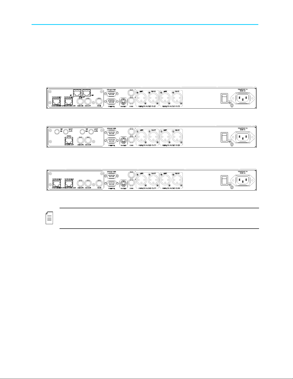
Figure 2-13 illustrates the ProView 2961 rear panel with an MPEGoIP input interface.
Figure 2-14 illustrates the ProView 2961 rear panel with DVB-S (QPSK) Dual Input
configuration.
Figure 2-15 displays the ProView 2961 rear panel with Decoder Only configuration.
Figure 2-13: ProView 2961 Rear Panel (IP Input interface)
Figure 2-14: ProView 2961 Rear Panel (DVB-S Dual Input interface)
Figure 2-15: ProView 2961 Rear Panel (Decoder Only interface)
NOTE
ProView 2900 models supporting MPEGoIP output and IP data out (MPE de-capsulation)
output can be configured to support either MPEGoIP or IP data out.
© Harmonic Inc. Manual p/n 101543/Ver 1.0 2-13 ProView 2900 Series/SW Version 1.94

Chapter 2: Introduction Characteristics and Specifications
2.4. Characteristics and Specifications
The following section provides with the ProView 2900 Characteristics and specification.
2.4.1. Transport Stream Interface Options
Feature Specifications
DVB-S
Single Input
DVB-S
Dual Input
DVB-DSNG
Single Input
Interface - F-type 75Ω
Constellation - QPSK
Single L-band input
Frequency range - 950-2150 MHz
RF Input level: (-65) – (-25) dBm
Symbol rate range - 1-45M Sym/s
L-Band RF input with LNB control and loop-through output
Interface - F-type 75Ω
Constellation - QPSK
Dual L-band input
Dual independent demodulators
Manual selection between inputs
Frequency range - 950-2150 MHz
Symbol rate range - 1-45M Sym/s
L-Band RF input with LNB control and loop-through output
Interface - F-type 75Ω
Constellation – QPSK, 8PSK and 16QAM
Single L-band input
Frequency range - 950-2150 MHz
Symbol rate range - 1-45M Sym/s
L-Band RF input with LNB control and loop-through output
© Harmonic Inc. Manual p/n 101543/Ver 1.0 2-14 ProView 2900 Series/SW Version 1.94

Chapter 2: Introduction Characteristics and Specifications
Feature Specifications
DVB-S2
Single Input
MPEGoIP Input
Applications - Broadcast services and DSNG EN 302 307
Mode – CCM, ACM
Constellations: QPSK, 8PSK, 16APSK
FEC frames: Normal (64800 bits), short (16200 bits)
Roll-Off: 0.35, 0.25, 0.20
Pilots – On, Off
Frequency range: 950 MHz - 2150 MHz
Symbol rate range – 1Msym/s - 45Msym/s
2 L-Band RF 75Ω inputs with LNB control
Modulation Scheme Recovery: Automatic (ACM mode)
Physical Layer Scrambling support
Multiple input transport stream (MSI) support using Input Stream
Identifier (ISI)
Two physical links - 10/100 Base-T, RJ-45 – one active at a time
Two logical sources (sockets) – one active at a time
Physical Link and logical source redundancy (coupled)
De-Jittering buffer size - configurable 100-2000mSec
TS bit rate: up to 44 Mbps
MPEGoIP output
DVB-ASI Input
Encapsulation type: UDP and RTP (Automatic detection)
SPTS/MPTS
Unicast/Multicast
IGMPv2
Forward Error Correction (FEC)
• ProMPEG CoP3v2
• Maximum input bit-rate: 25Mb/s
• Columns only FEC protection
• Matrix dimensions - Columns 1-20, Rows 4-20. Columns*Rows ≤
100 (Automatic detection)
TS bit rate - up to 60 Mbps
SPTS/MPTS
Encapsulation - UDP
All programs and PIDs are present in the output TS
Interface 10/100 Base-T, RJ-45
Interface: copper, BNC 75 ohm
TS bit rate: up to 100 Mbps (Byte and Burst mode)
© Harmonic Inc. Manual p/n 101543/Ver 1.0 2-15 ProView 2900 Series/SW Version 1.94

Chapter 2: Introduction Characteristics and Specifications
Feature Specifications
DVB-ASI Output
Telecom G.703
Input
DVB-PDH Input
2 ASI connectors: copper, BNC 75 ohm
ASI options:
• ASI OUT 1 - output stream with decrypted selected program,
output stream and loop-through
• ASI OUT 2 - output stream with decrypted selected program,
output stream
ASI output rate - up to 100 Mbps (Byte mode)
Unframed PDH Data rates::E1,E2 or E3
FEC (optional): DVB-C FEC
Loop-through output
Interface: ATM AAL-1
Data rates: DS3 or E3
Loop-through output
2.4.2. Advanced Processing
Feature Specifications
Service and PID
Filtering
Data
Active on ASI and IP outputs
PCR re-stamping
VBR and CBR modes (NULL stuffing)
Forward only and filter only modes
Dynamic Service filtering (tracks PIDs' modifications)
Static PID filtering
PSI/SI tables are not modified.
High speed data: RS-422 Up to 20 Mbps, RJ-45 (supported by
ProView 2960, ProView 2990)
IP Data Out (RJ-45): up to 60Mbps (MPE de-capsulation)
© Harmonic Inc. Manual p/n 101543/Ver 1.0 2-16 ProView 2900 Series/SW Version 1.94

Chapter 2: Introduction Characteristics and Specifications
2.4.3. Decoder Outputs
Feature Specifications
Video
Video Formats:
• PAL-B/G/I/M/N/D, NTSC, SECAM L/B/G/K1
• Russian SECAM D/K (composite video only supported only by
special order in ProView 2960, ProView 2961 and ProView 2990)
Decoding:
• 4:2:0 MP@ML (1.5 – 15 Mbps)
• 4:2:2 PP@ML (1.5 – 50 Mbps) (supported only in ProView 298x)
Maximum TS decoding bit rate: 108Mbps
Video resolution interpolation: Pan-scan, letter box or Pass through
Aspect ratios: 4:3/16:9
Aspect ratio 14:9 by signaling over VBI video index
Graphical processing (OSD): DVB subtitling, EBU (Teletext)
subtitling
OSD only through monitoring output
Genlock input and loop-through output and phase compensation
(supported only by ProView 2962, ProView 2963, ProView 2981 and
ProView 2992)
Genlock Sync lock resolution: +/- 37nSec
Front panel
Monitoring
VBI Re-insertion
Video monitor output connector (Supported only by 298x)
Audio monitor output connector (Supported only by 298x)
All VBIs adhere the relevant standards including the line numbers
In composite video and embedded SDI
WST Teletext and inverted Teletext
WSS, VPS, VITC, CC, AMOL I, AMOL II (Nielsen), TV-Guide, VCHIP
Enhanced VITS with built-in generator
© Harmonic Inc. Manual p/n 101543/Ver 1.0 2-17 ProView 2900 Series/SW Version 1.94
 Loading...