

Harmonic MIP-7100, MIP-7101, MIP-7600, MIP-7301, MIP-7300 Installation Manual
...
Spectrum™ MediaDeck 7000 Installation Guide
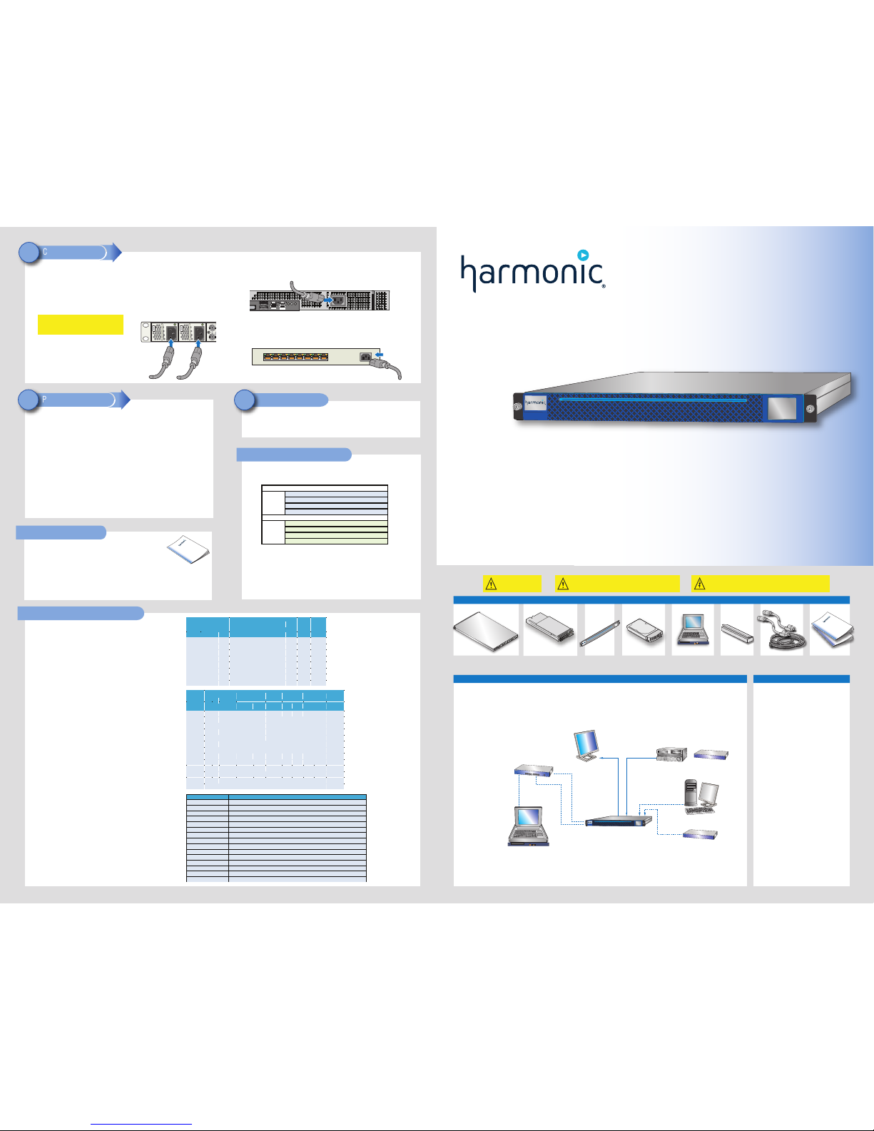
A sample system is shown below. Customer-supplied components include the following:
• Digital VTR (if an Analog VTR is used, external A-D converters are required)
• Video Monitors
• RS-422 interconnection cables (DB-9 Male to DB-9 Male)
• Audio/Video interconnection cables suitable for SDI and AES signal transmission, and monitoring equipment
• Gigabit Ethernet hub or Gigabit Ethernet switch
• Automation System (optional)
• Emergency Alert System (optional)
• Video router (optional)
Note: For complete environmental, power, racking, and cable requirements, refer to the Spectrum MediaDeck 7000 User Guide.
* For ChannelPort only.
Sample System Diagram
Spectrum MediaDeck 7000 Chassis Bezel Four 2-TB or 4-TB SATA
Disk Drives or four 480-GB
Solid-State Drives
SystemManager Platform
or Client PC
Rack Mount Kit Interconnection Cables
Warning: Safe handling
of this system requires
TWO people.
Caution: Electrostatic discharge can damage components. Make sure to wear
an antistatic wrist strap and attach it to a metal part of the MediaDeck chassis
when performing the procedures in this guide.
Part Number 28-0357, Revision F.
*Other names and brands may be claimed as the property of others.
Copyright © 2014. Harmonic Inc. All rights reserved.
Harmonic Technical Support can be contacted as follows:
For support in the Americas:
Telephone (Toll Free): +1 888 673 4896
Telephone (Local) +1 408 490 6477
Email: omneon.support@harmonicinc.com
For support in Europe, Middle East, and Africa:
Telephone: +44 1252 555 450
Email: omneonemeasupport@harmonicinc.com
For support in Russia and CIS
Telephone: +7 495 926 4608
Email: RUsupport@harmonicinc.com
For support in Japan:
Telephone: +81 3 5565 6737
Email: japansupport@harmonicinc.com
For support in China (mainland):
Telephone: +86 10 8391 3313
Email: chinasupport@harmonicinc.com
For support in Asia Pacific (other territories):
Telephone: +65 6542 0050
Email: apacsupport@harmonicinc.com
For the support page on the Harmonic website:
http://www.harmonicinc.com/services-support
For the support server:
ftp://ftp.omneon.com/Updates/Omneon/Current/
Rack Mount Kit
Technical Support
Documentation Suite
1. Apply power to the Ethernet hub or switch.
2. Apply power to the SystemManager Platform and Keyboard/Monitor Tray, or client PC.
3. From the SystemManager Platform, log on to Microsoft Windows with the user name:
Administrator, and the password: omneon. Both entries are case sensitive.
Note: If an error message appears indicating that a network connection is missing,
click OK and continue with the power-up sequence.
If you have installed SystemManager on a client PC, log on to your client PC.
4. Apply power to the MediaDeck by connecting the AC cords to the separate power sources.
5. Check the port status display on the MediaDeck front panel and verify there are no problems.
Refer to “Reading the Port Status Display.”
6. Apply power to the (optional) automation system.
Power Up the System
12
To run SystemManager and begin using your MediaDeck, and for an overview of ChannelPort
configuration, refer to “Getting Started with SystemManager” in the Spectrum MediaDeck 7000
User Guide.
Run SystemManager
13
Caution: Unpack and place your MediaDeck system on a flat
anti-static surface to perform the following installation procedures
contained in this document.
To replace components for your MediaDeck, refer to the Spectrum™
System Component Replacement Guide in your MediaDeck kit.
The Component Replacement Guide includes the following sections:
Replacing Components
• Replacing the Bezel
• Replacing a Disk Drive
• Replacing a Power Supply
• Replacing a MediaPort or ChannelPort Module
• Replacing the Chassis
To access the Spectrum MediaDeck 7000 and ChannelPort documentation, go to: ftp.omneon.com/updates/omneon/current/MediaDeck/
To access the Harmonic SystemManager software and documentation, go to: ftp.omneon.com/updates/omneon/current/SystemManager/
Refer to the Spectum MediaDeck 7000 Read Me First in your MediaDeck kit for the password to download the documentation and
software files for the Spectrum MediaDeck 7000 and SystemManager.
4. Connect an AC cord to the AC connector on the Ethernet switch (or hub). Do not plug the AC cord
into an AC power source yet.
Connect AC Power
11
2. MediaDecks do not have any power switches. To take full advantage of the dual redundant
power supplies on the MediaDeck, ensure that separate, isolated power sources are
available. Connect AC cords to the two AC connectors on the MediaDeck.
1. If you are connecting to an automation system, make sure the power switch on the automation
system is off. Attach an AC cord to the AC connector on the automation system.
3. Make sure that the power switch for the SystemManager Platform or client PC is off, and that the
power switch for the Keyboard/Monitor Tray is off as well. Attach an AC cord to the AC connector on
your SystemManager Platform or client PC as well as your SystemManager Keyboard/Monitor Tray.
SystemManager Platform Rear Panel
SystemManager Platform Rear Panel
Gb 1
Gb 2
8 1234567
Gigabit Ethernet Switch
Reading the Port Status Display
The following illustration identifies the types of information available on the port
status display on the front panel.
MediaPort and ChannelPort Options
Locate the following items in your Spectrum MediaDeck 7000 kit:
MediaPort 7000 or ChannelPort
Modules
NOTE: Alarms will cause the display to flash. To stop the flashing, resolve the alarm
or touch the display.
The Port Status Display allows you to enable the display of a static color bar pattern on any
or all of the SDI Output connectors, which can be used to verify connectivity. For more details,
refer to “Port Status Display” in the Spectrum MediaDeck 7000 User Guide.
The table to the right shows available MediaPort 7000 and ChannelPort
module options. Note that ChannelPort modules also support
Emergency Alert Systems. For more details on the MediaPort 7000 Module,
refer to “MediaPort 7000 Module Orientation” in the Spectrum MediaDeck
7000 User Guide. For more details on the ChannelPort Module, refer
to “ChannelPort Module Orientation” in the Spectrum MediaDeck
7000 User Guide.
MediaDeck Rear Panel
Important: Do not plug the AC cords into AC
power sources yet. Connecting to an AC power
source will turn on the MediaDeck.
Port Status Display
Status
of
Module A
Health Summary and MediaPort ID
Channel 0: Player name, Player state, and mecode
IP address and environmental alarms, if any
Status
of
Module B
Reference Input
IP address and environmental alarms, if any
Health Summary and
MediaPort ID
Reference Input
Channel 1: Player name, Player state, and mecode
Channel 0: Player name, Player state, and mecode
Channel 1: Player name, Player state, and mecode
MediaPort 7000 and ChannelPort Module Options
License Options
Automation System (optional)
Spectrum MediaDeck 7000
SystemManager Platform
or Client PC
A/V Out
Ethernet
Switch or Hub
A/V In
GPIO/RS-422
Ethernet
Host
Connections
Digital VTR
Video Out
Video Router (optional)*
or
Emergency Alert
System (optional)*
GPIO/
RS-422
The table to the right shows product IDs for licensed features for MediaPort
7000 and ChannelPort modules. Note that ChannelPort supports Play only.
The table to the right shows additional licensed features available for
MediaPort 7000 and ChannelPort modules. Note that the IDs beginning with
“CPL” are available for ChannelPort modules only.
Additional License Options
*Upgrading to this license requires that an HD license is already present
on the ChannelPort or MediaPort module.
Note that for ChannelPorts with 4 graphics layers enabled (4GL), U/D/X
conversion is not included with the DMH, DVH, and M2H licenses
unless explicitly upgraded for that capability. For ChannelPorts with 8
graphics layers enabled and MediaPorts, U/D/X conversion is included with
the DMH, DVH, and M2H licenses unless you are upgrading from a 4GL version.
NOTE: Spectrum supports AVC/H.264 playout at at PitchBlue operating
points only.
®
Product ID SD HD
Up /Down/
Cross
Conversion
and HD/SD
Simulcast
MPEG-2 DV/DVCPRO AVC-Intra
VC-3 ProRes
Rec Play Rec/Play Rec
Play
Rec Play Play
APR X X X X X X X
DMH X X X X X
DMS X X X X
DVH X X X X
DVS X X
M2H X X X X
M2S X X
M2R X X
UVP X X X X X X
VC3* X X X X X X
VC3P* X X X X
VC3R* X X X X
SPL-PRORES X
Product ID
Description
MPU-7000-M2R
License upgrade to add MPEG-2 Record to any MediaPort 7000
SPL-OPC
Onboard playout control for one channel of Spectrum ChannelPort or MediaPort 7000
SPL-OMF
Onboard Media Fetch for one channel of Spectrum ChannelPort or MediaPort 7000
SPL-STL
Onboard subtitle insertion license for one channel of Spectrum ChannelPort or MediaPort 7000
SPL-OCC
Onboard closed caption insertion license for one channel of Spectrum ChannelPort or MediaPort 7000
CPL-MCS
Master Control (Live Input) license upgrade for one ChannelPort module (2 ch)
CPL-DVE
License upgrade to enable capability for a single DVE for one ChannelPort module (2 ch)
CPL-HD
HD license upgrade (no U/D/X Conversion) for one ChannelPort module (2 ch)
CPL-H264-PLAY
License upgrade for PitchBlue® TS demux and H.264 decode for PitchBlue operating points only (2 ch)
CPL-UDX*
U/D/X Converter license upgrade (HD option is also required) for one ChannelPort module (2 ch)
CPL-AVC-INTRA-PLAY*
Decode of AVC-Intra for one ChannelPort module (2 ch)
CPL-MAX-GRAPHIC-LAYERS
License upgrade to enable the maximum number of graphics layers on a ChannelPort module (2 ch)
CPL-ENHANCED-CHANNEL
License upgrade to enable Spectrum Enhanced Channel mode on a ChannelPort module
CPL-INDEP-BRANDING
License upgrade to enable Independent SD/HD Branding on a ChannelPort module (2 ch)
CPL-DUAL-DVE
License upgrade to enable Dual DVE functionality on a ChannelPort module (2 ch)
Model
Number
H.264
Proxy
MPEG-2 DV/DVCPRO AVC-Intra
VC-3
ProRes
Graphics
Layers
AVC/H.264
Rec
Play
Rec
Play
Rec
Play
Rec
Play
Play
Play
MIP-7100 X X X X X X X
MIP-7101 X X X X X X X X
MIP-7300 X X X X X X X
MIP-7301 X X X X X X X X
MIP-7600 X X X X X X X X X
MIP-7601 X X X X X X X X X X
CPT-8100 X X X X X X X
CPT-8200 X X X X X X X
For complete instructions on rack mounting the Spectrum MediaDeck 7000 system, refer
to the instructions provided with the rack kit and the Spectrum MediaDeck 7000
User Guide.
Rack Mount the System
1
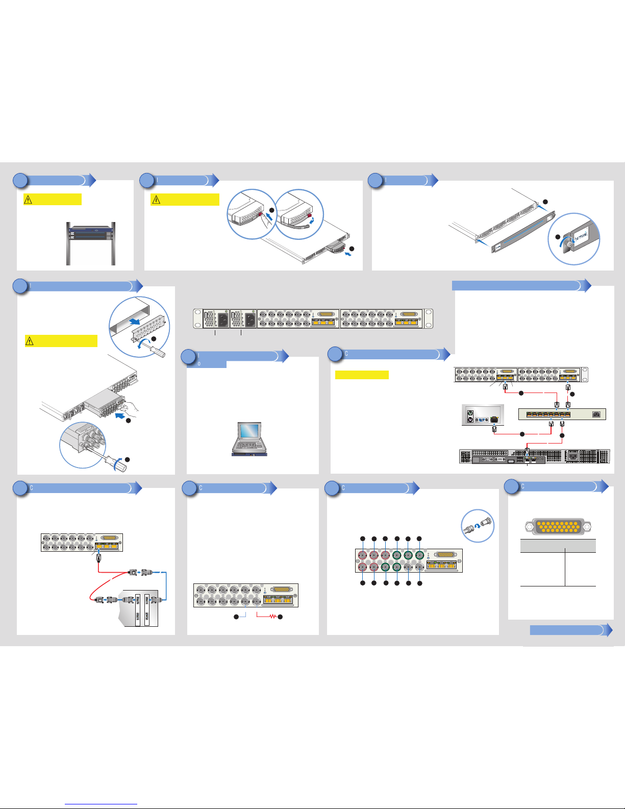
1. Align the bezel in front of the chassis so that the
front panel display appears in the top-right corner,
and the metal corners of the bezel are level with the
rack ears of the chassis.
Note: Use TWO hands to perform this procedure.
3. Hand-tighten the two captive thumb screws to
secure the bezel in place.
2. Keeping the corners aligned, press the bezel straight
onto the chassis.
Install the Bezel
3
4. Install the remaining disk drives.
Note: Disk drives can be installed in any order.
1. Unpack a disk drive.
2. Press the red release button on the right side of the
disk drive to release the handle.
Install the Disk Drives
2
Caution: Electrostatic discharge can damage components.
Observe normal ESD [Electrostatic Discharge] procedures
when handling hard drive assemblies.
Spectrum MediaDeck 7000 Rear View
Warning: Safe handling of this system
requires TWO people.
3. Push the drive into the chassis until the handle begins
to close, and then press the handle until it closes. The
handle will click as it closes.
The SystemManager application, used to operate and configure the MediaDeck, comes preinstalled on the SystemManager Platform. The software-only version of SystemManager can be
installed and run on your own client PC.
To install either the SystemManager Platform or the software-only version of SystemManager,
refer to the Harmonic SystemManager Release Notes and Harmonic SystemManager Installation
Guide for instructions. These guides can be downloaded from:
ftp.omneon.com/updates/omneon/current/SystemManager/
Refer to the Spectrum MediaDeck 7000 Read Me First in your MediaDeck kit for help with
downloading the necessary files.
SystemManager Platform
or
Software-only version
Install the SystemManager Platform
or Client PC
5
The following diagram describes the functionality of BNC connectors for the MediaPort 7000 module.
Your system configuration and specific audio/video requirements may differ.
For a descriptions of ChannelPort Module connectors, see the Spectrum ChannelPort 8100/8200
Module Quick Reference Guide, Spectrum Installation and Hardware Reference Guide, or the
Spectrum MediaDeck 7000 User Guide.
BNC
Connector
Detail
Connect Audio and Video I/O
9
Continued on the next page
Connect GPIO/RS-422 (Optional)
10
Connect Reference Video
8
9 8
7 6
5
4
18 17
16 15
13 12 11 10
26
25
24 23
22
21 20 19
13 2
14
The MediaPort 7000 and ChannelPort modules have a female GPIO
connector that can be connected to an external device and used to control
players. On a ChannelPort, this connector also provides RS-422 signals
and can be used to control graphics, or connected to an Emergency Alert
System (EAS). The following describes the connector pins.
Power Supplies and LEDs
Module A
Module B
PS 0
PS 1
Your file transfer system may be any system you use for editing or network storage. The MediaDeck supports file
transfers using FTP, SAMBA, and AFP protocols.
4. Attach an Ethernet cable to the Ethernet switch, and then attach the other end to the LAN port on your file
transfer system.
5. Attach an Ethernet cable to the Ethernet port on the second MediaPort 7000 or ChannelPort module, and then attach
the other end to an open port on the Ethernet switch.
Connect to a File Transfer System (Recommended)
Connect to your Gigabit Ethernet Network
6
Note: For the following connections, Harmonic recommends that you use a CAT 5e or CAT 6
Ethernet cable. Do not use a crossover cable or an adapter.
1. Ensure that an Ethernet switch with Gigabit uplink capability has been installed in your
equipment rack.
2. Attach an Ethernet cable to the NIC 1 port on the SystemManager Platform, or an open
LAN port on your client PC. Attach the other end of the Ethernet cable to the Ethernet switch.
Note: Do not use the NIC 2 port on the SystemManager Platform unless you have
configured SystemManager as a client, or you are using the NSM-2003. Refer to the
Harmonic SystemManager Installation Guide for details.
3. Attach an Ethernet cable to the Ethernet port on one of the MediaPort 7000 or ChannelPort
modules, and then attach the other end to an open port on the Ethernet switch. The MediaDeck
uses DHCP to obtain an IP address, or an IP address can be assigned to it statically.
Connect to SystemManager
Important: Check with your network administrator
before connecting to your Ethernet network.
Connect to your Gigabit Ethernet Network (Continued)
75 Ohm
Termination
(or loop to
next device)
2
1
ReferenceReference
1. Connect reference video to one of the Reference connectors.
2. Connect a 75 Ohm BNC terminator to the other Reference connector to terminate
it, or connect it to the next device in line that requires reference video.
Note: Termination must be applied to the last device in the loop.
3. If required, configure VITC lines using the SystemManager. For details, refer to
“Changing MediaDirector Clock Reference VITC Lines” in the Harmonic SystemManager
User Guide.
Make sure to always connect reference video to at least one MediaPort or ChannelPort module
in the MediaDeck. Failure to connect reference video may result in errors. Note that two MediaPort
7000 or ChannelPort modules can share reference video as long as it is connected to one module.
You may also connect a different type of reference (525 or 625) to each MediaPort or ChannelPort
module and the system will automatically select the correct reference type for each attached player.
MediaPort 7000 or ChannelPort Module
2
3
Install the MediaPort or ChannelPort Modules
4
1. If you are installing two modules, you may need to first remove
a filler panel from the chassis. From the rear of the MediaDeck,
unscrew the two lock screws that secure the filler panel, and then
remove it.
2. Grasp the module handle and push firmly into the
slot. Ensure the module is fully inserted by pressing
on the connectors with the palm of your hand.
Caution: Do not use the two lock screws on the rear
panel of the module to pull it into position. Tighten the
screws only after the module is fully inserted.
4. Repeat steps 2-3 for the second module.
2
3
Sample Automation System Connection
Note: All DB-9 Male to
Male extension cables
in these diagrams are
customer supplied.
The RJ-45 to DB-9 cable
is supplied by Harmonic.
Refer to the User Guide
for pinout information.
All automation systems differ in their array of control connectors and methods of interfacing with the MediaDeck
system. The following diagram provides one example. For instructions on connecting a ChannelPort module to
an automation system, refer to “Connecting a ChannelPort Module to an Automation System” in the Spectrum
MediaDeck 7000 User Guide. Refer to the documentation supplied with your automation system for
interconnection details.
Connect to an Automation System (Optional)
7
VTR
Play
Record
PVW
422
(3)
422
(4)
422
(1)
422
(2)
Record
Automation System Rear Panel
RJ45 Male to
DB-9 Female Splitter
Play
MediaPort 7000 Module
RS-422
Port A/B
8 1234567
Gigabit Ethernet Switch
MediaPort 7000 or ChannelPort Modules Rear Panel
5
LAN
File Transfer System Rear Panel
4
SystemManager Platform Rear Panel
Gb 1
Gb 2
2
NIC 1
3
EthernetRS-422
Unused
3. Tighten the two lock screws on the rear of the module
to secure it to the chassis.
For information on configuring GPIO on a MediaPort using SystemManager,
refer to “MediaPort Configuration” in the Harmonic SystemManager User
Guide. For information on configuring GPIO on a ChannelPort, refer to
“ChannelPort Configuration” in the Harmonic SystemManager User Guide.
For information on connecting a ChannelPort to an EAS, refer to “Connecting
a ChannelPort to an Emergency Alert System” in the Spectrum MediaDeck
7000 User Guide.
1
2
3 456
8 9
10 11
12
7
(MediaPort 7000 Module or ChannelPort Module) (MediaPort 7000 Module or ChannelPort Module)
1
Function
RX (-/+)
TX (-/+)
GPIO/RS-422 Signals
Function
Pin
Ground
Ground 18
Serial
0
2-3
GPIO 0
19
GPIO 1 20
Serial 1
GPIO 2 21
GPIO 3 22
Serial 2
GPIO 4 23
GPIO 5 24
Serial 3
GPIO 6 25
GPIO 7 26
8-9
10-11
16-17
1
6-7
4-5
14-15
12-13
1. HD/SD SDI IN
Channel A
2. HD/SD SDI OUT Channel A (Primary)
3. HD/SD SDI OUT Channel A (Secondary)
4. HD/SD SDI IN Channel B
5. HD/SD SDI OUT Channel B (Primary)
6. HD/SD SDI OUT Channel B (Secondary)
7.
8. LTC OUT
Channel A
9. LTC IN Channel B
10. LTC OUT Channel B
11. Reference Loop
LTC IN Channel A
12. Reference Loop
MediaPort 7000 Module
3
2
 Loading...