

Harmonic Electra 1000 Installation Manual

Electra 1000™
Multichannel Encoder
Installation Guide
Rev M
Manual Part No. MAN-ELECTRA1000-3.0

Disclaimer
Harmonic reserves the right to alter the equipment specifications and descriptions in this publication without prior notice. No part of
this publication shall be deemed to be part of any contract or warranty unless specifically incorporated by reference into such
contract or warranty. The information contained herein is merely descriptive in nature, and does not constitute a binding offer for
sale of the product described herein. Harmonic assumes no responsibility or liability arising from the use of the products described
herein, except as expressly agreed to in writing by Harmonic. The use and purchase of this product do not convey a license under
any patent rights, copyrights, trademark rights, or any intellectual property rights of Harmonic. Nothing hereunder constitutes a
representation or warranty that using any products in the manner described herein will not infringe any patents of third parties.
Trademark Acknowledgments
Harmonic and all Harmonic product names are trademarks of Harmonic Inc. All other trademarks are the property of their respective
owners.
Compliance and Approval
This equipment has been tested and found to comply with the limits for a Class A digital device, pursuant to Part 15, Subpart B of the
Federal Communications Commission (FCC) rules.
These limits are designed to provide reasonable protection against harmful interference when the equipment is operated in a
commercial environment.
This equipment generates, uses, and can radiate radio frequency energy. It may cause harmful interference to radio communications
if it is not installed and used in accordance with the instructions in this manual. Operation of this equipment in a residential area is
likely to cause harmful interference. If this occurs, the user will be required to correct the interference at his or her own expense.
This device complies with Part 15 of the FCC rules. Operation is subject to the following two conditions: (1) this device may not
cause harmful interference, and (2) this device must accept any interference received, including interference that may cause
undesired operation.
Connections between the Harmonic equipment and other equipment must be made in a manner that is consistent with maintaining
compliance with FCC radio frequency emission limits. Modifications to this equipment not expressly approved by Harmonic may
void the authority granted to the user by the FCC to operate this equipment.
WEEE/RoHS Compliance Policy
Harmonic Inc. intends to comply fully with the European Union’s Directive 2002/96/EC as amended by Directive 2003/108/EC, on
Waste Electrical and Electronic Equipment, also known as “WEEE,” and Directive 2002/95/EC, as amended, on the Restriction of
use of Hazardous Substances, also known as “RoHS.”
Harmonic will ensure that product which cannot be reused will be recycled in compliance with the WEEE Directive. To that end,
users are advised that (1) Harmonic equipment is not to be discarded in household or office garbage, (2) Harmonic Inc. will pay the
freight for shipment of equipment to be disposed of if it is returned to Harmonic, (3) customers should call the normal RMA
telephone numbers to arrange for such shipment, and (4) for additional and updated information on this process customers may
consult the Harmonic website: http://harmonicinc.com/ah_weee_recycle.cfm.
Harmonic will ensure that its products will be either reused or recycled in compliance with the WEEE Directive. For the latest
information concerning Harmonic’s WEEE/RoHS Compliance Policy and its Recycling and Take-Back process, please visit our Web
site.
© 2012 Harmonic Inc. All rights reserved.

产品中的有毒有害物质或元素的名称及含量表
Names and Contents of the Toxic and Hazardous Substances or Elements in the
Products if the Part is Present
该表显示哈雷公司产品中可能含有的有毒有害物质元配件的信息,除了来源于元配件供应商的物料成分资料,
亦来自其它相关的机构与资料。哈雷产品不一定使用这些元配件。
This table shows those components where hazardous substances may be found in Harmonic products based on, among other
things, material content information provided by third party suppliers. These components may or may not be part of the product.
除非特殊注明,哈雷公司产品的环保使用期限 均为 20 年。该环保使用期限的有效条件为:必须遵循该产品使
用手册的规定,对该产品进行使用或存储。
The Environmental Protective Use Period for Harmonic products is 20 years unless displayed otherwise on the product. The EPUP
period is valid only when the products are operated or stored as per the conditions specified in the product manual.
有毒有害物质或元素 (Hazardous Substance)
部件名称 (Part name)
铅
(PB) 汞(Hg)镉(Cd)
六价铬
(CrVI)
多溴联苯
(PBB)
多溴二苯醚
(PBDE)
印刷线路板
(Printed Circuit Assemblies)
机械组件
(Mechanical Subassemblies)
光学组件
(Optical Subassemblies)
电源
(Power Supplies)
缆线 / 线束
(Cables, harnesses)
屏幕 / 显示器
(Screens, Monitors)
金属零件
(Metal Parts)
塑
料 / 发泡材料
(Plastics, foams)
电池
(Batteries)
XOO O O O
XOO O O O
XOO O O O
XOO O O O
XOO O O O
XOO O O O
OOO O O O
OOO O O O
XOO O O O
O: 表示在该部件的所有均质材料中,此类有毒有害物质的含量均小于 SJ/T11363-2006 标准所规定的限量。
O: Indicates the content of the toxic and hazardous substances at the homogeneous material level of the parts is below the limit
defined in SJ/T11363 2006 standard.
X: 表示至少在该部件的某一均质材料中,此类有毒有害物质的含量超出 SJ/T11363-2006 标准规定的限量。
X: Indicates that the content of the toxic and hazardous substances in at least one of the homogeneous materials of the parts is
above the limit defined in SJ/T11363 2006 standard.
© 2012 Harmonic Inc. All rights reserved.

Standards and Agency Approval
The following tables list regulatory standards and agency approvals:
North America
Standards Agency Approval
EMI: FCC Part 15, Subpart B, ICES-003, Issue 2, Class A FCC
Safety: UL 60950, CSA 60950 cTUV-us Mark
Europe
Standards Agency Approval
EMI/EMC: EN55022, Class A, EN55024 CE
Safety: EN 60950 TUV-GS-Mark, CE
Japan
Standards Agency Approval
EMI: VCCI V-3 / 2000.04 VCCI
Australia and New Zealand
EMI: AS/NZS-3548: 1995 +A1: 1997 +A2: 1997 N/A
Standards Agency Approval
© 2012 Harmonic Inc. All rights reserved.
Documentation Conventions
This manual uses some special symbols and fonts to call your attention to important information. The
following symbols appear throughout this manual:
DANGER: The Danger symbol calls your attention to information that, if ignored, can cause physical
harm to you.
CAUTION: The Caution symbol calls your attention to information that, if ignored, can adversely affect
the performance of your Harmonic product, or that can make a procedure needlessly difficult.
LASER DANGER: The Laser symbol and the Danger alert call your attention to information about the
lasers in this product that, if ignored, can cause physical harm to you.
NOTE: The Note symbol calls your attention to additional information that you will benefit from
heeding. It may be used to call attention to an especially important piece of information you need, or it
may provide additional information that applies in only some carefully delineated circumstances.
TIP: The Tip symbol calls your attention to parenthetical information that is not necessary for performing
a given procedure, but which, if followed, might make the procedure or its subsequent steps easier,
smoother, or more efficient.
In addition to these symbols, this manual uses the following text conventions:
Data Entry: indicates text you enter at the keyboard.
User Interface: indicates a button to click, a menu item to select, or a key or key sequence
to press.
Screen Output: shows console output or other text that is displayed to you on a
computer screen.
Bold: indicates the definition of a new term.
Italics: used for emphasis, cross-references, and hyperlinked cross-references in online
documents.
© 2012 Harmonic Inc. All rights reserved.

Table of Contents
Table of Contents
Chapter 1 Preface
1.1 Manual Organization. . . . . . . . . . . . . . . . . . . . . . . . . . . . . . . . . . . . . . . . 9
Chapter 2 Introduction
2.1 Operating Environment . . . . . . . . . . . . . . . . . . . . . . . . . . . . . . . . . . . . 10
2.2 General Features . . . . . . . . . . . . . . . . . . . . . . . . . . . . . . . . . . . . . . . . . 10
2.3 Video Encoding Features . . . . . . . . . . . . . . . . . . . . . . . . . . . . . . . . . . 12
2.4 Audio Encoding Features . . . . . . . . . . . . . . . . . . . . . . . . . . . . . . . . . . 13
2.5 DiviTrackIP Support . . . . . . . . . . . . . . . . . . . . . . . . . . . . . . . . . . . . . . . 13
2.6 Digital Program Insertion Support . . . . . . . . . . . . . . . . . . . . . . . . . . . 14
2.7 Audio Mode Change Control Through VANC . . . . . . . . . . . . . . . . . . 14
2.8 Standard Closed-Captions Support . . . . . . . . . . . . . . . . . . . . . . . . . . . 14
2.8.1 Japanese Standard Closed Caption Support . . . . . . . . . . . . . . . . . . . 15
2.8.2 ARIB B-37 Captions . . . . . . . . . . . . . . . . . . . . . . . . . . . . . . . . . . . . . . . 15
2.9 Front Panel . . . . . . . . . . . . . . . . . . . . . . . . . . . . . . . . . . . . . . . . . . . . . . 15
2.9.1 Front Bezel . . . . . . . . . . . . . . . . . . . . . . . . . . . . . . . . . . . . . . . . . . . . . . 15
2.9.2 Local Control Panel . . . . . . . . . . . . . . . . . . . . . . . . . . . . . . . . . . . . . . . 15
2.9.3 LEDs . . . . . . . . . . . . . . . . . . . . . . . . . . . . . . . . . . . . . . . . . . . . . . . . . . . 15
2.9.4 Modes of Operation . . . . . . . . . . . . . . . . . . . . . . . . . . . . . . . . . . . . . . . 16
2.10 Back Panel . . . . . . . . . . . . . . . . . . . . . . . . . . . . . . . . . . . . . . . . . . . . . . 16
2.10.1 AC Power and Fuse . . . . . . . . . . . . . . . . . . . . . . . . . . . . . . . . . . . . . . 17
2.10.2 DC Power and Fuse . . . . . . . . . . . . . . . . . . . . . . . . . . . . . . . . . . . . . . 17
2.10.3 Audio Input Ports . . . . . . . . . . . . . . . . . . . . . . . . . . . . . . . . . . . . . . . . 17
2.10.4 Video Input Ports . . . . . . . . . . . . . . . . . . . . . . . . . . . . . . . . . . . . . . . . 18
2.10.5 IP Output Port . . . . . . . . . . . . . . . . . . . . . . . . . . . . . . . . . . . . . . . . . . . 18
2.10.6 Ethernet Management Port . . . . . . . . . . . . . . . . . . . . . . . . . . . . . . . . 18
2.10.7 Fault Relay Port . . . . . . . . . . . . . . . . . . . . . . . . . . . . . . . . . . . . . . . . . . 18
2.10.8 Serial Data Port . . . . . . . . . . . . . . . . . . . . . . . . . . . . . . . . . . . . . . . . . . 19
2.11 Back Panel LEDs . . . . . . . . . . . . . . . . . . . . . . . . . . . . . . . . . . . . . . . . . 19
2.11.1 Main Board LEDs . . . . . . . . . . . . . . . . . . . . . . . . . . . . . . . . . . . . . . . . . 19
2.11.2 Video Lock LEDs . . . . . . . . . . . . . . . . . . . . . . . . . . . . . . . . . . . . . . . . . 19
2.11.3 Audio Port LEDs . . . . . . . . . . . . . . . . . . . . . . . . . . . . . . . . . . . . . . . . . 19
Chapter 3 Installation
3.1 Preparation . . . . . . . . . . . . . . . . . . . . . . . . . . . . . . . . . . . . . . . . . . . . . . 20
3.2 Unpacking . . . . . . . . . . . . . . . . . . . . . . . . . . . . . . . . . . . . . . . . . . . . . . . 20
3.3 Installing the Encoder in a Rack . . . . . . . . . . . . . . . . . . . . . . . . . . . . . 20
3.3.1 Rack Guidelines . . . . . . . . . . . . . . . . . . . . . . . . . . . . . . . . . . . . . . . . . . 21
3.3.2 Chassis Warnings for Rack Mounting and Servicing . . . . . . . . . . . . . 21
3.3.3 Airflow . . . . . . . . . . . . . . . . . . . . . . . . . . . . . . . . . . . . . . . . . . . . . . . . . 21
3.3.4 Attaching the Rack Rails . . . . . . . . . . . . . . . . . . . . . . . . . . . . . . . . . . . 22
3.3.5 Mounting the Encoder . . . . . . . . . . . . . . . . . . . . . . . . . . . . . . . . . . . . . 23
3.4 Installing Encoder Software . . . . . . . . . . . . . . . . . . . . . . . . . . . . . . . . . 23
© 2012 Harmonic Inc. 6 Electra 1000, Version 3.0, Rev M

Table of Contents
3.5 Cabling the Encoder . . . . . . . . . . . . . . . . . . . . . . . . . . . . . . . . . . . . . . 24
3.5.1 Back Panel . . . . . . . . . . . . . . . . . . . . . . . . . . . . . . . . . . . . . . . . . . . . . . 24
3.5.2 Connecting the Audio Input Cables . . . . . . . . . . . . . . . . . . . . . . . . . 24
3.5.3 Connecting the Video Input Cables . . . . . . . . . . . . . . . . . . . . . . . . . 25
3.5.4 Connecting the IP Output Cables . . . . . . . . . . . . . . . . . . . . . . . . . . . 25
3.5.5 Connecting the Ethernet Management Cable . . . . . . . . . . . . . . . . . 25
3.5.6 Connecting the AC Power . . . . . . . . . . . . . . . . . . . . . . . . . . . . . . . . . 25
3.5.7 Connecting the DC Power Supply . . . . . . . . . . . . . . . . . . . . . . . . . . . 26
Chapter 4 Operating the Encoder
4.1 Operating with NMX Digital Service Manager . . . . . . . . . . . . . . . . . . 27
4.2 Using the Front Panel . . . . . . . . . . . . . . . . . . . . . . . . . . . . . . . . . . . . . 27
4.2.1 The Keypad . . . . . . . . . . . . . . . . . . . . . . . . . . . . . . . . . . . . . . . . . . . . . 27
4.2.2 Front Panel Display . . . . . . . . . . . . . . . . . . . . . . . . . . . . . . . . . . . . . . . 28
4.2.3 Setting the Encoder Network Properties . . . . . . . . . . . . . . . . . . . . . . 28
4.2.4 Viewing the Encoder MAC Address . . . . . . . . . . . . . . . . . . . . . . . . . 29
4.2.5 Viewing the Encoder Serial Number . . . . . . . . . . . . . . . . . . . . . . . . . 29
4.3 Using SAG . . . . . . . . . . . . . . . . . . . . . . . . . . . . . . . . . . . . . . . . . . . . . . . 29
4.3.1 Preparing the Computer . . . . . . . . . . . . . . . . . . . . . . . . . . . . . . . . . . . 30
4.3.2 Accessing the Standalone GUI (SAG) . . . . . . . . . . . . . . . . . . . . . . . . 30
4.4 Licensing Information . . . . . . . . . . . . . . . . . . . . . . . . . . . . . . . . . . . . . . 32
Chapter 5 Maintenance and Troubleshooting
5.1 Air Filters . . . . . . . . . . . . . . . . . . . . . . . . . . . . . . . . . . . . . . . . . . . . . . . . 33
5.1.1 Maintaining the Air Filters . . . . . . . . . . . . . . . . . . . . . . . . . . . . . . . . . 33
5.1.2 Removing and Replacing the Air Filters . . . . . . . . . . . . . . . . . . . . . . 34
5.2 Fuse . . . . . . . . . . . . . . . . . . . . . . . . . . . . . . . . . . . . . . . . . . . . . . . . . . . . 35
5.2.1 Replacing the Fuse . . . . . . . . . . . . . . . . . . . . . . . . . . . . . . . . . . . . . . . 35
5.3 Contacting Harmonic Support . . . . . . . . . . . . . . . . . . . . . . . . . . . . . . . 35
Appendix A Audio and Video Specifications
A.1 AIC Features . . . . . . . . . . . . . . . . . . . . . . . . . . . . . . . . . . . . . . . . . . . . . 37
5.3.1 PCM Downmix from 5.1 . . . . . . . . . . . . . . . . . . . . . . . . . . . . . . . . . . . 38
5.3.2 5.3.2 Re-encode Ability . . . . . . . . . . . . . . . . . . . . . . . . . . . . . . . . . . . . 38
A.2 MPEG-1 Layer II Audio . . . . . . . . . . . . . . . . . . . . . . . . . . . . . . . . . . . . 39
A.3 Dolby Digital (AC-3) Audio . . . . . . . . . . . . . . . . . . . . . . . . . . . . . . . . . 39
A.4 Video Specifications . . . . . . . . . . . . . . . . . . . . . . . . . . . . . . . . . . . . . . 41
Appendix B Encoder Specifications
B.1 Environment Specifications . . . . . . . . . . . . . . . . . . . . . . . . . . . . . . . . 42
B.2 Port Specifications . . . . . . . . . . . . . . . . . . . . . . . . . . . . . . . . . . . . . . . 43
B.3 Port Pinouts . . . . . . . . . . . . . . . . . . . . . . . . . . . . . . . . . . . . . . . . . . . . . 44
B.3.1 Ethernet Management Port . . . . . . . . . . . . . . . . . . . . . . . . . . . . . . . . 44
B.3.2 Fault Relay/GPI Ports . . . . . . . . . . . . . . . . . . . . . . . . . . . . . . . . . . . . . 45
B.3.3 Analog Audio Input Ports . . . . . . . . . . . . . . . . . . . . . . . . . . . . . . . . . . 46
B.3.4 Cable Pinouts and External 708 Closed Captioning . . . . . . . . . . . . 47
Appendix C Encoder Back Panel Slot Locations
© 2012 Harmonic Inc. 7 Electra 1000, Version 3.0, Rev M

Table of Contents
C.1 Adapter Configurations for All Encoders . . . . . . . . . . . . . . . . . . . . . . 48
C.1.1 Additional Card Configurations for FLEX-based Encoders . . . . . . . 48
C.1.2 Viewing the Control Board (CPC) Revision Information . . . . . . . . . . 49
Appendix D Boot Sequence
D.1 Local Control Panel Display Messages during Bootup . . . . . . . . . . . 50
D.2 Other Local Control Panel Display Messages . . . . . . . . . . . . . . . . . . 50
D.2.1 Resetting the Encoder . . . . . . . . . . . . . . . . . . . . . . . . . . . . . . . . . . . . 50
D.2.2 Loading New Software . . . . . . . . . . . . . . . . . . . . . . . . . . . . . . . . . . . . 51
Appendix E Wiring the –48 VDC Power Supply
E.1 Getting Started . . . . . . . . . . . . . . . . . . . . . . . . . . . . . . . . . . . . . . . . . . . 52
E.2 Power Source Specifications . . . . . . . . . . . . . . . . . . . . . . . . . . . . . . . . 52
E.3 Overcurrent Protection . . . . . . . . . . . . . . . . . . . . . . . . . . . . . . . . . . . . 52
E.4 Wiring Requirements . . . . . . . . . . . . . . . . . . . . . . . . . . . . . . . . . . . . . . 53
E.5 Power Connector . . . . . . . . . . . . . . . . . . . . . . . . . . . . . . . . . . . . . . . . . 53
E.6 Assembling the DC Input Power Cable . . . . . . . . . . . . . . . . . . . . . . . 54
Appendix F FLEX Decoding Module
F.1 Introduction . . . . . . . . . . . . . . . . . . . . . . . . . . . . . . . . . . . . . . . . . . . . . 55
F.2 Video Decoding Specifications . . . . . . . . . . . . . . . . . . . . . . . . . . . . . . 55
F.3 Audio Passthrough Specifications . . . . . . . . . . . . . . . . . . . . . . . . . . . 56
F.4 Audio Decode Specifications . . . . . . . . . . . . . . . . . . . . . . . . . . . . . . . 57
F.4.1 Decoding Resource Considerations . . . . . . . . . . . . . . . . . . . . . . . . . 57
F.5 Ancillary Data Specifications . . . . . . . . . . . . . . . . . . . . . . . . . . . . . . . . 59
F.6 Input Specifications . . . . . . . . . . . . . . . . . . . . . . . . . . . . . . . . . . . . . . . 59
F.7 Output Specifications . . . . . . . . . . . . . . . . . . . . . . . . . . . . . . . . . . . . . . 60
F.8 Environmental and Physical . . . . . . . . . . . . . . . . . . . . . . . . . . . . . . . . 61
F.9 Module Slots . . . . . . . . . . . . . . . . . . . . . . . . . . . . . . . . . . . . . . . . . . . . . 61
F.10 Installing the FLEX Decoding Module . . . . . . . . . . . . . . . . . . . . . . . . 61
F.10.1 Installing a Module . . . . . . . . . . . . . . . . . . . . . . . . . . . . . . . . . . . . . . . . 61
F.11 Cabling the FLEX Module . . . . . . . . . . . . . . . . . . . . . . . . . . . . . . . . . . 62
F.12 Re-Encode Chassis Scenarios . . . . . . . . . . . . . . . . . . . . . . . . . . . . . . . 62
F.12.1 2 - Channel . . . . . . . . . . . . . . . . . . . . . . . . . . . . . . . . . . . . . . . . . . . . . . 62
F.12.2 4 - Channel . . . . . . . . . . . . . . . . . . . . . . . . . . . . . . . . . . . . . . . . . . . . . . 64
F.13 Configuring the FLEX Module in NMX . . . . . . . . . . . . . . . . . . . . . . . . 64
Appendix G RF Input Card
G.1 RF Specifications . . . . . . . . . . . . . . . . . . . . . . . . . . . . . . . . . . . . . . . . . 65
G.2 Output Specifications . . . . . . . . . . . . . . . . . . . . . . . . . . . . . . . . . . . . . . 66
G.3 Environmental and Physical . . . . . . . . . . . . . . . . . . . . . . . . . . . . . . . . 66
Appendix H A/B Power Input Switch
H.1 Introduction . . . . . . . . . . . . . . . . . . . . . . . . . . . . . . . . . . . . . . . . . . . . . 67
H.2 Card Status . . . . . . . . . . . . . . . . . . . . . . . . . . . . . . . . . . . . . . . . . . . . . . 68
Index 69
© 2012 Harmonic Inc. 8 Electra 1000, Version 3.0, Rev M

This manual describes the Harmonic DiviCom™ Electra™ 1000 Multichannel Encoder.
1.1 Manual Organization
This manual contains the following chapters:
Chapter 2, Introduction, introduces the encoder and describes its features.
Chapter 3, Installation, provides a hardware overview, including a description of the back
panel ports, connector specifications, and rack-mounting instructions.
Chapter 4, Operating the Encoder, describes how to begin configuring the encoder using
NMX or the front panel.
Chapter 5, Maintenance and Troubleshooting, describes maintenance and what to do in the
event of problems.
Appendix A, Audio and Video Specifications, provides specifications for AIC,and video
encoding.
Appendix B, Encoder Specifications, describes specifications and physical characteristics of
the back panel ports and port pinouts, environment specifications, and input and output
specifications.
Appendix C, Encoder Back Panel Slot Locations, shows the numbering of the back panel
slots. NMX uses the slot number to differentiate between cards of the same type within
the encoder.
Appendix D, Boot Sequence, describes the encoder boot sequence, including the
messages that appear on the front panel.
Appendix E, Wiring the –48 VDC Power Supply, provides specifications for the optional DC
power supply and wiring instructions.
Appendix F, FLEX Decoding Module, provides details about the FLEX decoding module.
Appendix G, RF Input Card, provides specifications for the RF Input Card
Appendix H, A/B Power Input Switch, provides specifications for the optional A/B Power
Input Switch card.
Chapter 1
Preface
© 2012 Harmonic Inc. 9 Electra 1000, Version 3.0, Rev M

The Harmonic Electra™ 1000 Multichannel Encoder provides multichannel standard
definition MPEG-2 encoding and DiviTrackIP™ statistical multiplexing. It accepts up to four
analog composite or serial digital standard definition video inputs, and up to ten analog or
digital audio inputs. The encoder operates within an IP environment, allowing flexible network
architectures.
This chapter describes:
The environment in which you can operate the Electra 1000
General features
Video encoding features
Audio encoding features
Support for DiviTrackIP and DPI
The front and back panels
2.1 Operating Environment
The encoder operates under the control of NMX™ Digital Service Manager. NMX manages
multiple Electra 1000 encoders and other devices. NMX provides full configuration of the
Electra 1000 platform, ports, services, and PSI, as well as alarm management. You configure
a few initial network settings from the front panel of the encoder. The encoder operates within
an IP environment; therefore, encoders and multiplexers do not need to be in the same
physical location. Harmonic recommends discussing your planned network architecture with
a Harmonic representative before implementation.
Chapter 2
Introduction
2.2 General Features
Tab le 2-1 describes general features supported by the Electra 1000. See the following tables
for more information about video and audio compression.
Table 2-1: General Features
Feature Description
Hardware
Chassis
Local control panel
Software
Control
Upgrades
Compact, 1-RU
Mounts in Electronic Industries Association (EIA) standard rack
Two-line, 20-character vacuum fluorescent display (VFD)
24-button keypad (includes Help key)
Four status LEDs
NMX Digital Service Manager or Configuration Manager
Front control panel (for setting management IP address)
From NMX (see the NMX online help for details)
© 2012 Harmonic Inc. 10 Electra 1000, Version 3.0, Rev M

Chapter 2 Introduction General Features
Table 2-1: General Features
continued
Feature Description
Video input Up to four video encoders per chassis
Accepts 525-line (NTSC) and 625-line (PAL) standard serial
digital and analog composite video in the same chassis.
525-line analog may be either NTSC or PAL-M
Accepts 525-line serial digital video.
Audio input Digital and analog stereo inputs
Up to 10 stereo pairs
Up to 20 mono channels using a single PID per channel with
MPEG-1Layer II compression
Complete embedded audio extraction of eight pairs from four
groups, from serial digital video input (48 kHz synchronous to
video only)
AAC and HE AAC
HE AACv2
Transcoding of Dolby-E into Dolby Digital 5.1 with backup from
a
stereo compression optional
PCM, plus simultaneous 2.0 encoding from PCM into AC3 on
on-board /AIC board
Transcoding of Dolby Digital into Digital Plus (5.1, 2.0)
AHC-561 Dolby-E decode 5.1 (2.0). Only port 1 is capable of
Multichannel (3/2) on the AHC-561 or AHC-RAC.
Fixed Audio Gain (AIC card)
Low Delay Audio Encoding
Audio description for audio coding (AIC RAC and on-board
audio)
Dolby Digital Plus passthrough
IP output MPEG-2 Transport Stream (TS) over UDP
One 10/100/1000 Base-T port with second redundant
channel/connector
Dual-mode IP output or manual channel switch for redundancy
Hot/warm standalone IP channel redundancy
Same-source IP output support
Automatic port redundancy
UDP encapsulation support
Unicast and multicast address support
Ping and ARP support
Single-program transport stream (SPTS) and multiple-program
transport stream (MPTS) outputs
Null packets can be preserved to match the exact rate of SPTS
(video server integration)
Connector type: RJ-45
DPI support SCTE104
SCTE104 messaging for 525-compatibility
PSI support Generated by NMX when managed by NMX
Alarms Current and history alarm logs in NMX Alarm Manager
SNMP alarm forwarding
IRIS™ Support Data reporting (loss/corrupted and silent audio) of input audio
© 2012 Harmonic Inc. 11 Electra 1000, Version 3.0, Rev M

Chapter 2 Introduction Video Encoding Features
a. HE AAC, also known as aacPlus, was developed by Dolby Germany. Dolby Digital,
Dolby Digital Plus, aacPlus, and Dolby E are trademarks of Dolby Laboratories.
Trademarks of Coding Technologies GmbH are the property of Coding
Technologies GmbH. All rights reserved.
2.3 Video Encoding Features
Tab le 2-2 describes video encoding features supported by the encoder.
Table 2-2: Video Encoding Features
Feature Support
Input format Serial digital or analog composite
Video format Serial digital: 525-lines or 625-lines
Analog composite: NTSC, PAL, and PAL-M
Encoding mode MPEG-2 MP@ML 4:2:0 encoding
Repeat field
Supported
detection
Horizontal
720, 704, 640, 544, 528, 480, 352
resolutions
Advanced encoding Alternate scan mode, zig-zag mode, flexible GOP structure,
4:3 and 16:9 aspect ratio
Video preprocessing ENRGY™ Integrated Noise Reduction System
Horizontal filter, border processing, nonlinear spatial filter,
impulse noise reduction, motion compensated temporal low
pass filter (MCTF), luma and chroma filter, and edge-adaptive
texture filter
PSIP tables spooling
Closed captioning Line 21
ATSC Line 21 CEA-608
ITU-R BO.1294
DVS-157 (GI CC)
SCTE 20 (True DVS-157)
SAUD (SA CC)
DMV1 (Tandberg CC)
DVS-157+SAUD
Extend Data Services (XDS)
(525-line VBI) 608 to 708 conversion
VBR Support for variable bit rate encoding
Capped VBR (open loop)
Accommodates poor
quality video sources
To compensate for poor analog sources, the encoder
preprocesses the area around the line sync, slightly expanding
both the front and back porches to enhance timing recovery.
As a result, the encoder slightly reduces the line length. When
this capability is engaged, all alarm reporting is disabled.
© 2012 Harmonic Inc. 12 Electra 1000, Version 3.0, Rev M

Chapter 2 Introduction Audio Encoding Features
2.4 Audio Encoding Features
Tab le 2-3 describes audio encoding features supported by the encoder.
Table 2-3: Audio Encoding Features
Feature Support
Stereo pairs Up to 10 stereo pairs
Two stereo pairs per audio input card
Input format Digital: AES3 or S/PDIF
Analog: balanced or unbalanced
Analog reference
level specification
Reference levels in the range -10 dBu to +4 dBu may be specified
in 0.5 dBu steps. Alignment tone at reference level is placed at
-20 dBFS per SMPTE RP155.
Audio encoding
format
24 bit audio
MPEG-1 Layer II (stereo) compression, and passthrough (digital
input only; embedded audio not supported)
Analog and digital
Single channel, dual, stereo, and joint stereo
Single PID per channel support with MPEG-1 Layer II
Supported
sampling resolution
THD+noise 0.0032% measured at –3bBFS
Audio sampling
Up to 48 kHz
frequency
Input adapter gain
Tied to standards and industry practice
structure
Compliant VBV Disable function supported for the audio-video buffer verifier to
allow larger buffer size
Single PID per
channel
Supported for MPEG-2 Layer II audio compression
Allows two audio circuits per adapter port for up to 20 mono
channels
2.5 DiviTrackIP Support
DiviTrackIP statistical multiplexing provides high-performance video compression when
multiple channels share a specified bandwidth. The system maintains the overall pool
bandwidth at a constant bit rate while allocating to individual channels the optimum number
of bits on a frame-by-frame basis, driven by picture complexity information from the
LookAhead™ analysis. By assigning priorities, you can specify channels that must maintain a
high quality when stress on the system increases.
The Electra 1000 encoder works in conjunction with NMX and a ProStream™ 1000 to
support DiviTrackIP. The ProStream 1000 analyzes the complexity of all incoming video
streams and sends messages to the encoders through the IP network. All streams from an
Electra 1000 encoder must be sent to the same ProStream 1000. MPTS (multiple STC clocks
per chassis) is also supported.
© 2012 Harmonic Inc. 13 Electra 1000, Version 3.0, Rev M

Chapter 2 Introduction Digital Program Insertion Support
Tab le 2-4 provides DiviTrack IP pool specifications. See the NMX help for information about
configuring DiviTrackIP.
Table 2-4: DiviTrackIP Pool Specifications
Parameter Description
Maximum number of DiviTrackIP pools per ProStream
1000
Maximum number of VBR services 12 8
Maximum number of channels per pool 64
Minimum stream bit rate 300 Kbps
Maximum stream bit rate MPEG 2 encoders: 15 Mbit/s
Maximum CPC 2.0 bitrate
Maximum CPC 2.5 bitrate
2.6 Digital Program Insertion Support
The Electra 1000 encoder supports digital program insertion (DPI). Electra 1000 accepts
external automation system DPI commands (triggers) via Ethernet. These commands are sent
via the SCTE 104 protocol, and result in the encoder placing SCTE 35 DPI messages in the
outgoing MPEG Transport Stream (TS). (The Electra 1000 also accepts commands via the
SCTE DVS/525 draft protocol.)
The resulting messages carry metadata used by downstream content insertion equipment to
choose and insert the proper content. When using an external automation system, that
system provides the metadata values via the SCTE 104 commands. The metadata is included
in the resulting SCTE 35 messages, which are placed in the outgoing MPEG Transport Stream.
8
SD AVC encoders: 8 Mbit/s
HD AVC encoders: 24 Mbit/s
40 Mbit/s
100 Mbit/s
2.7 Audio Mode Change Control Through VANC
The Electra 1000 (with AHC-RAC audio adapters mounted) can support one 5.1 channel
AAC audio stream plus one stereo audio stream maximum per encoder. Changes in the
audio coding may be controlled through messages in VANC when the AHC-RAC is suitably
provisioned.
2.8 Standard Closed-Captions Support
The CEA-708 closed captions include space for CEA-608 data. The encoder can receive
them either via serial port (compliant with SMPTE 333M , one service per chassis), or in
VANC (compliant with SMPTE 334-1, one service per encoder card mounted). Extraction of
CEA-608 data from Line 21 of SD video is also supported.
The placement of CEA-708 captions into the MPEG-2 video ES is compliant with ATSC A/53
Part 4. Placement of CEA-608 data is available compliant with a variety of industry standard
and proprietary methods. Consult the NMX or SAG online help for more details.
© 2012 Harmonic Inc. 14 Electra 1000, Version 3.0, Rev M
Chapter 2 Introduction Front Panel
2.8.1 Japanese Standard Closed Caption Support
The Ion AVC HD provides support for Japanese standard captions compliant with ARIB B24.
The Ion AVC HD encoder supports extraction (from VANC) compliant with ARIB B 37.
2.8.2 ARIB B-37 Captions
This refers to the Japanese standard and the input is in VANC while the captions are placed in
a separate PID.
2.9 Front Panel
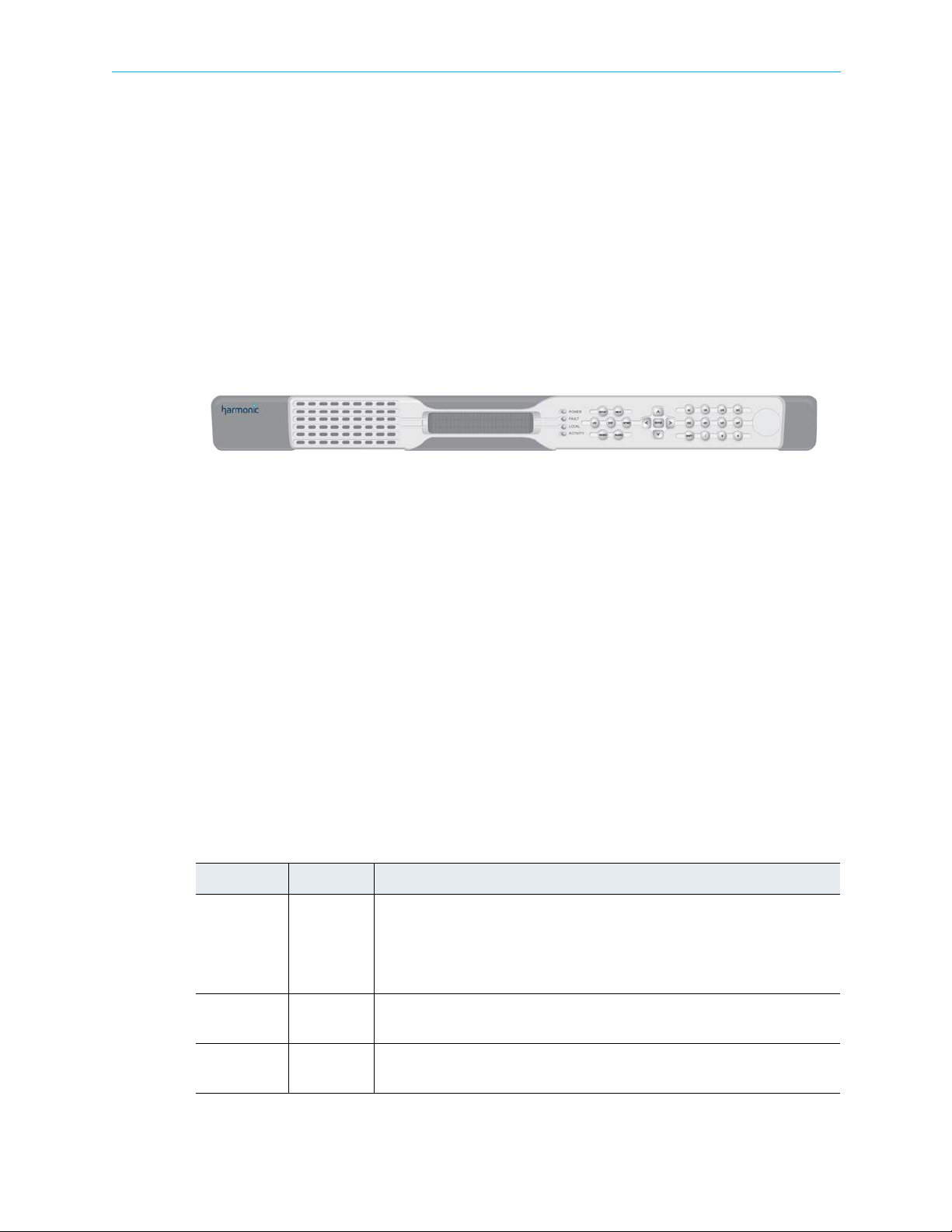
Figure 2-1 shows the front panel of the Electra 1000 encoder.
Figure 2-1: Front panel
2.9.1 Front Bezel
The encoder has a detachable front bezel that snaps on top of the local control panel and
provides access to the reusable air filters. See
cleaning the air filters.
2.9.2 Local Control Panel
The local control panel allows configuration of the initial network settings for the encoder.
From the front panel, you can set the encoder IP address, subnet mask, and default gateway,
and view the encoder MAC address.
2.9.3 LEDs
The four LEDs on the front panel indicate the operational state of the encoder. Tab le 2-5
describes the front panel LEDs.
Table 2-5: Front Panel LEDs
LED Color Description
Power Yellow The Power LED is yellow while the encoder initializes after
Green The Power LED turns green when the encoder initialization is
5.1 Air Filters on page 33 for information about
startup.
complete and the management interface is enabled and ready.
Fault Red The Fault LED lights when the application software detects an
alarm.
Local Yellow The Local LED lights when the encoder is operating in local
mode.
© 2012 Harmonic Inc. 15 Electra 1000, Version 3.0, Rev M

Chapter 2 Introduction Back Panel
Table 2-5: Front Panel LEDs
LED Color Description
Activity Yellow The Activity LED lights when the encoder generates an MPEG-2
2.9.4 Modes of Operation
There are three modes of operation on the encoder and are set globally through the NMX
interface for all encoder platforms and locally on SAG as well.
Default Mode
Verbose Front Panel Mode
NMX Control Over Second Line
2.9.4.1 Default Mode
The default mode (with no provision from the NMX application) is the default mode. For more
information on the default mode refer to the NMX online help
2.9.4.2 Verbose Front Panel
The front panel displays the device name on line one and either the card number or
Broadcast Operations Control (BOC) as well as the (sliding) service name on the second line.
For more information on the verbose front panel refer to the NMX online help
continued
transport stream. It blinks slowly when MPEG packets are being
transmitted steadily. It blinks fast or intermittently when the
transmission rate is slow or intermittent.
2.9.4.3 NMX Control Over Second Line
Under this option you can the front panel classic display mode as well as channel name and
bitrate. For more information on the NMX control on the second line refer to the NMX online
help.
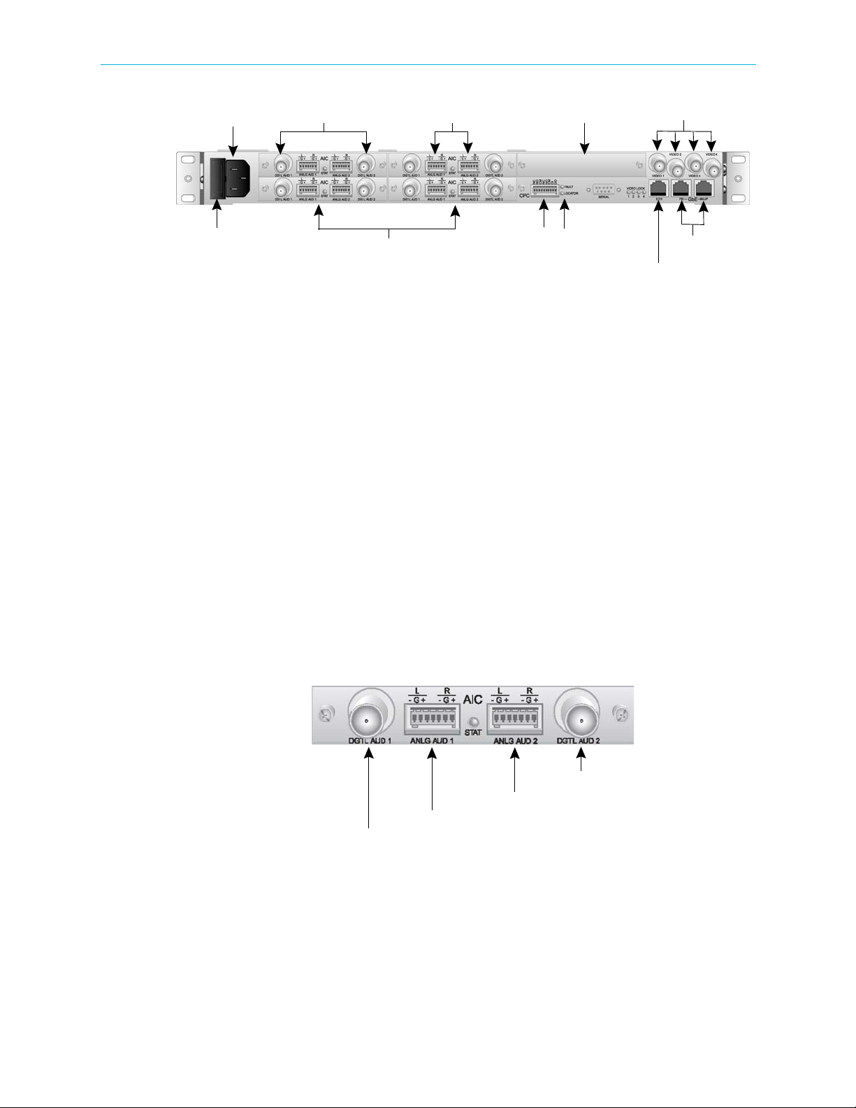
2.10 Back Panel
The back panel contains the following elements, as shown in Figure 2-2:
AC power plug and fuse or DC power
supply
Up to ten stereo digital and analog audio
input ports (two stereo digital audio
input ports per AIC)
Up to four video input ports
Video lock LEDs
Fault relay port
Fault and Locator LEDs
NOTE: Refer to Table C-1 on page 48 for information on which adapters/cards/modules are supported in
your back panel.
Serial data input port (reserved for future
use)
One 10/100 Base-T Ethernet
management port
One 10/100/1000 Base-T Fast Ethernet
output port with second redundant
channel and connector
© 2012 Harmonic Inc. 16 Electra 1000, Version 3.0, Rev M
Chapter 2 Introduction Back Panel
AC Power
Fuse Cover
Audio Input Cards
Digital Audio Input Ports
Fault and
Locator LEDs
Fault
Relay
Port
Ethernet
Management Port
Ethernet
Output Ports
Plug
Video Input Ports
Analog Audio Input Ports Expansion Slot
Digital Audio Input Port 2
Digital Audio Input Port 1
Analog Audio Input Port 1
Analog Audio Input Port 2
Figure 2-2: Back panel
2.10.1 AC Power and Fuse
The AC power plug accommodates standard IEC 120 VAC and 250 VAC power cords. The
chassis does not have a power switch. The unit powers on automatically when you plug it in.
See 3.5.6 Connecting the AC Power on page 25 for cabling instructions.
The fuse panel is located beside the power plug. The encoder requires one slow blow 4.0 A,
250 V fuse, 5 x 20 mm. See
5.2 Fuse on page 35 for replacement instructions.
2.10.2 DC Power and Fuse
If your encoder includes the optional DC power supply, see Appendix E, Wiring the –48 VDC
Power Supply, for more information about the power supply.
2.10.3 Audio Input Ports
Each AIC has two stereo analog audio input ports and two digital audio input ports (BNC
connectors). The encoder supports up to five AICs.
Figure 2-3 illustrates the audio input ports on an AIC.
Figure 2-3: Audio input ports
© 2012 Harmonic Inc. 17 Electra 1000, Version 3.0, Rev M

Chapter 2 Introduction Back Panel
2.10.3.1 Analog Audio Input Ports
Two Phoenix™ 1881480 6-pin connector ports support balanced or unbalanced stereo
analog audio input to the AIC.
The connector that mates to the analog ports is a Phoenix 1881367 connector. See
B.3.3 Analog Audio Input Ports on page 46 for pinout information.
2.10.3.2 Digital Audio Input Ports
Two BNC ports support AES3 or S/PDIF to provide the stereo digital audio input to the AIC
module.
2.10.4 Video Input Ports
The back panel contains up to four video input ports. These are BNC coaxial ports that
support standard definition serial digital video input or composite format.
Each video input port connects internally to a video processing card (VPC) The video
processing cards are not visible from the encoder back panel.
See 3.5.3 Connecting the Video Input Cables on page 25 for cabling instructions.
2.10.5 IP Output Port
One 10/100/1000 Base-T Ethernet port provides two redundant IP output channels. The two
RJ-45 connectors are labeled GbE PRI and BKUP.
The IP output port supports manual redundancy. The port also supports hot/warm standalone
redundancy: when the primary IP data channel detects a cable disconnection, the primary
channel stops outputting, and the backup channel takes over.
In manual redundancy, you can enable one channel or both channels. If you enable one
channel, you must manually switch to the other channel after a service-affecting alarm. If you
enable both channels, the encoder outputs the same data from both channels.
See 3.5.4 Connecting the IP Output Cables on page 25 for cabling instructions. Set the IP address
and other network information for the IP output ports using NMX.
2.10.6 Ethernet Management Port
The Ethernet management port, labeled ETH, is 10/100 Base-T and uses an RJ-45/UTP cable
to connect to an Ethernet network. See
page 25 for cabling instructions. See B.3.1 Ethernet Management Port on page 44 for pinout
information.
2.10.7 Fault Relay Port
The fault relay port connects to a Form C relay that can switch up to 0.25 amps at 30 VDC.
See
B.3.2 Fault Relay/GPI Ports on page 45 for port pinout and additional information.
3.5.5 Connecting the Ethernet Management Cable on
The encoder energizes the fault relay during normal operation. The fault condition is indicated
in the same way as the encoder’s powered-off condition, which is with the relay de-energized.
You can use this method to correctly identify a power supply failure or loss of input power.
The signals are normally open or normally closed.
NOTE: Any alarm causes the fault relay to change to the fault state. When multiple alarms accumulate,
all alarms must be active for the relay state to change.
© 2012 Harmonic Inc. 18 Electra 1000, Version 3.0, Rev M

Chapter 2 Introduction Back Panel LEDs
2.10.8 Serial Data Port
The serial data port may be supported at some future time.
2.11 Back Panel LEDs
The following sections describe the back panel LEDs and their functions.
2.11.1 Main Board LEDs
The back panel contains two LEDs on the main board. Tab le 2-6 describes the LEDs located
on the main board.
Table 2-6: Rear Panel Main Board LEDs
LED Color Description
Locator Blue The Locator LED lights when this encoder is enabled through
NMX. Use the Locator LED to help you identify a specific chassis
in a rack.
Fault Red The Fault LED lights when the application software detects an
alarm. The front panel and back panel Fault LEDs light at the same
time.
2.11.2 Video Lock LEDs
Each video port has an associated Video Lock LED. Ta ble 2-7 describes the LED located on
each video port.
Table 2-7: Rear Panel Video Lock LEDs
LED Color Description
Video 1
Video 2
Green When illuminated and steady, the Video Lock LED indicates that
2.11.3 Audio Port LEDs
Each AIC contains a status LED. Tab le 2-8 describes the LED located on each AIC.
Table 2-8: Rear Panel Audio Port LEDs
LED Color Description
STAT Blue The Audio Port LED is on during bootup as the audio input card
the video signal is locked. When off, the Video Lock LED indicates
that the encoder has lost video sync.
comes online. The LED is off during normal operation.
© 2012 Harmonic Inc. 19 Electra 1000, Version 3.0, Rev M

This chapter provides detailed instructions for installing a Electra 1000 encoder in a standard
19-inch rack and connecting cables.
The chapter describes:
How to prepare and unpack the Electra 1000
How to install the encoder in a rack
How to update the encoder software
How to connect the cables
3.1 Preparation
You need a Phillips screwdriver to mount the encoder in a standard 19-inch rack. Harmonic
ships the necessary rack-mount screws and rack rails.
3.2 Unpacking
The encoder comes in a specially designed shipping container that ensures the integrity of
your encoder hardware during shipping and handling. To avoid damage to the component,
follow the unpacking instructions that come with the encoder.
Chapter 3
Installation
When you unpack the encoder, you should find the following items:
Encoder
Standard IEC power cord
Spare air filters
Software warranty agreement
Harmonic ships rack-mounting kits in a separate shipping container.
3.3 Installing the Encoder in a Rack
You can install the encoder in different sizes and types of racks. For rack assembly
instructions, consult the manual that came with the rack or the customer service department
of the rack manufacturer.
This section describes how to mount the encoder in a standard 19-inch rack, using the two
side-mount rails included in the rack-mounting kit. A 30-inch-deep rack with a spacer or
chimney between racks with multiple encoders is the recommended rack setup. However,
these rails work for racks that are 30 to 36 inches deep.
When you view the rack from the rear, the power rail should be installed on the left side.
© 2012 Harmonic Inc. 20 Electra 1000, Version 3.0, Rev M

Chapter 3 Installation Installing the Encoder in a Rack
3.3.1 Rack Guidelines
When operating the encoder in the rack, ensure that:
The ambient temperature around the unit (which may be higher than room temperature)
is within the limit specified for the unit.
There is sufficient airflow around the unit.
Electrical circuits are not overloaded; consider the nameplate rating of all the connected
equipment.
There is overcurrent protection.
The equipment is properly grounded.
No objects are placed on top of the unit.
3.3.2 Chassis Warnings for Rack Mounting and Servicing
CAUTION: To prevent bodily injury when mounting or servicing this unit in a rack, you must take special
precautions to ensure that the system remains stable. The following guidelines are provided to ensure your
safety.
This unit should be mounted at the bottom of the rack if it is the only unit in the rack.
If the rack will hold a number of units, load the rack from the bottom to the top with the
heaviest component at the bottom of the rack.
If the rack is provided with stabilizing devices, install the stabilizers before mounting or
servicing the unit in the rack.
ATTENTION: Pour éviter toute blessure corporelle pendant les opérations de montage ou de réparation
de cette unité en casier, il convient de prendre des précautions spéciales afin de maintenir la stabilité du
système. Les directives ci-dessous sont destinées à assurer la protection du personnel.
Si cette unité constitue la seule unité montée en casier, elle doit être placée dans le bas.
Si cette unité est montée dans un casier partiellement rempli, charger le casier de bas en
haut en plaçant l’élément le plus lourd dans le bas.
Si le casier est équipé de dispositifs stabilisateurs, installer les stabilisateurs avant de
monter ou de réparer l'unité en casier.
WAR N U NG: Zur Vermeidung von Körperverletzung beim Anbringen oder Warten dieser Einheit in einem
Gestell müssen sie besondere Vorkehrungen treffen, um sicherzustellen, daß das System stabil bleibt. Die
folgenden Richtlinien sollen zur Gewährleistung Ihrer Sicherheit dienen.
Wenn diese Einheit die einzige im Gestell ist, sollte sie unten im Gestell angebracht
werden.
Bei Anbringung dieser Einheit in einem zum Teil gefüllten Gestell ist das Gestell von unten
nach oben zu laden, wobei das schwerste Bauteil unten im Gestell anzubringen ist.
Wird das Gestell mit Stabilisierungszubehör geliefert, sind zuerst die Stabilisatoren zu
installieren, bevor sie die Einheit im Gestell anbringen oder sie warten.
3.3.3 Airflow
The airflow through the encoder is critical for maintaining the proper temperature range. Fans
in the chassis draw air in through the front bezel and through the encoder. The airflow
ventilates out the right side (front view).
© 2012 Harmonic Inc. 21 Electra 1000, Version 3.0, Rev M
Chapter 3 Installation Installing the Encoder in a Rack
CAUTION: Do not obstruct the airflow of the encoder. Severe equipment damage can result when the
encoder cannot properly exhaust the airflow.
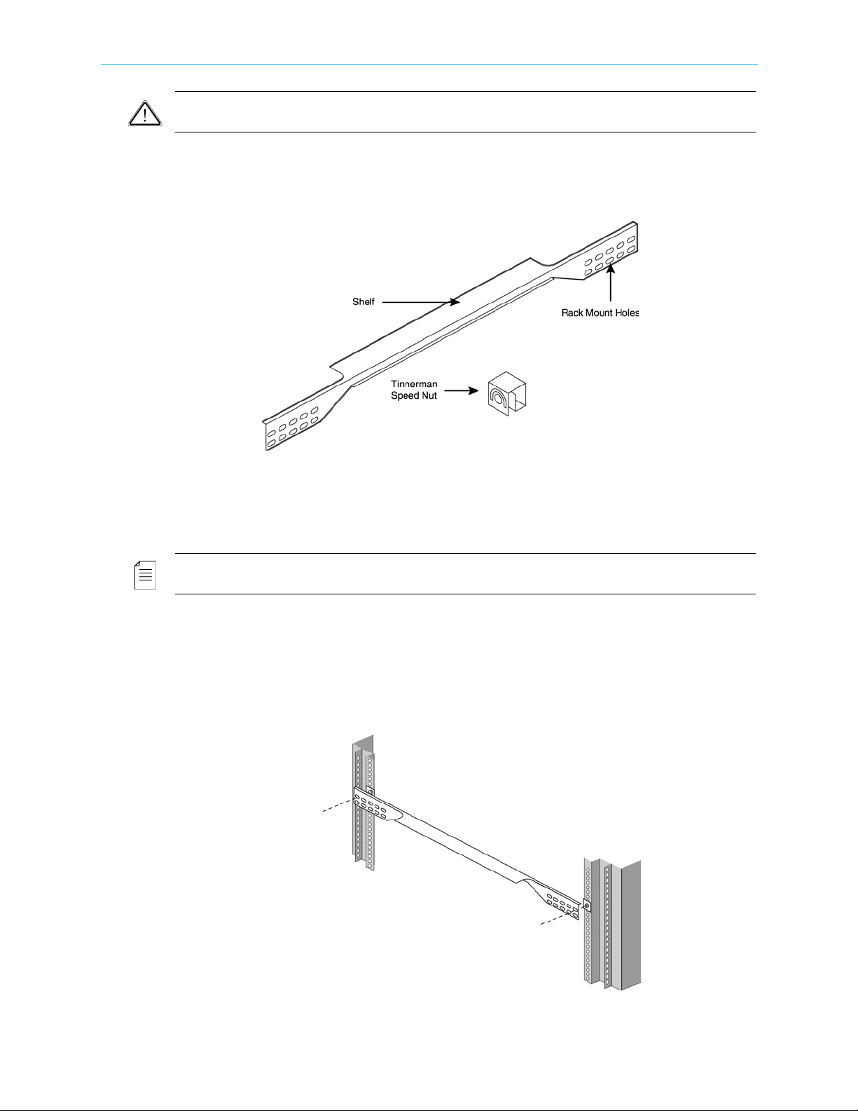
3.3.4 Attaching the Rack Rails
Attach the side-mount rack rails to the rack to hold the encoder in place. Figure 3-1 illustrates
the parts of the rack rails.
Figure 3-1: Rack rails
To attach the rack rails to the rack:
1. If needed, place a Tinnerman™ speed nut with the nut on the outside of the rack over the
holes to which you would like to mount the rails.
NOTE: Each of the four rack posts requires two speed nuts.
2. Position the rack rails so the shelves are toward the inside of the rack.
3. Using the #10 screws provided with the encoder, screw the mounts into the speed nuts
from the inside of the rack using the rack-mount holes that line up with the holes on the
rack posts.
Figure 3-2 illustrates attaching the rails.
Figure 3-2: Attaching the rails to the rack
© 2012 Harmonic Inc. 22 Electra 1000, Version 3.0, Rev M
 Loading...