

Page 1
installation guide
Installation guide
Electronic intelligent timer thermostat
www.harmonithermostat.co.uk
Page 2

2
installation guide
Contents
Page
1 Introduction ....................................................... 3
1.1 Technical specifications ................................ 4
1.2 Safety Instructions ........................................ 7
2 Mounting Instructions ...................................... 8
3 Settings ............................................................. 12
3.1 Initial settings ............................................... 12
3.2 Forecast ....................................................... 16
3.3 Window open ............................................... 18
3.4 Maximum floor temperature .......................... 19
3.5 Enable/Disable timer ..................................... 23
4 Symbols ............................................................. 24
5 Disposal Information ........................................ 25
6 Warranty ............................................................ 25
More information on this product can be found at:
www.harmonithermostat.co.uk
Page 3

3
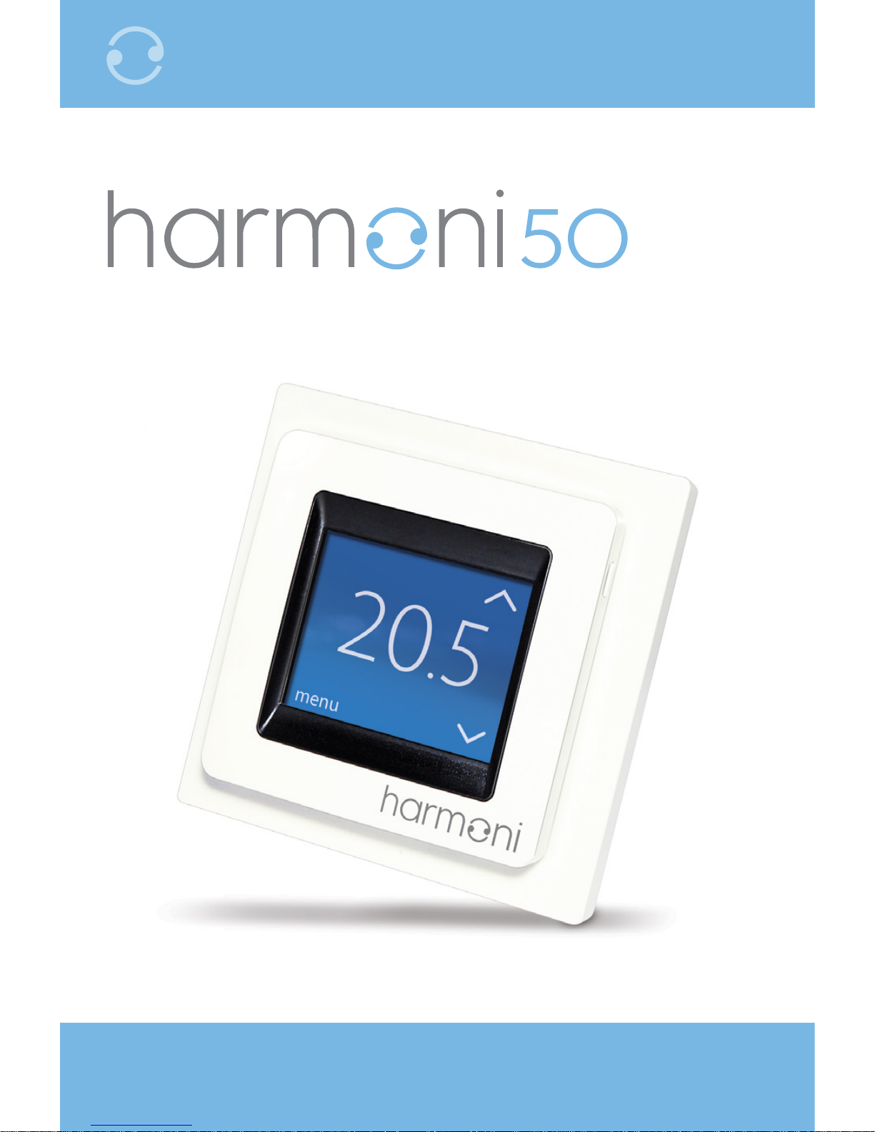
harmoni 50
Introduction 1
harmoni 50 is an electronic programmable timer
thermostat used for controlling electrical underfloor
heating elements.
The thermostat is designed for fixed installation only. It
can be used for both direct heating of the entire room
and for comfort heating of the floor.
Listed below are some of the thermostat’s main features:
h A touchscreen display with backlight.
h Easy-to-follow menu-driven programming and
operation.
h An installation wizard with room/floor type specific
set-up.
h Support for multiple frame systems.
h Compatible with numerous 3rd party NTC sensors.
h Settings can be copied from one thermostat to
another/others using a single generated code.
Page 4

4
installation guide
Technical Specifications 1.1
Operation voltage 220–240 V~
Standby power consumption Max. 0.40 W
Relay:
Resistance load
Inductive load
Max. 16 A / 3680 W @ 230 V
cos φ = 0.3 Max. 1 A
Sensing units NTC 6.8 kOhm at 25°C
NTC 10 kOhm at 25°C
NTC 12 kOhm at 25°C
NTC 15 kOhm at 25°C (default)
NTC 33 kOhm at 25°C
NTC 47 kOhm at 25°C
Sensing values: (default NTC
15 K)
0°C
20°C
50°C
42 kOhm
18 kOhm
6 kOhm
Control PWM (Pulse Wide Modulation)
Ambient temperature 0° to +30°C
Frost protection temperature 5°C to +9°C (default 5°C)
Page 5

5
harmoni 50
Temperature range Room temperature 5–35°C.
Floor temperature 5–45°C.
Max. floor: 20–35°C (if
unrecoverable seal is broken
then up to 45°C).
Min. floor: 10–35°C, only with
combination of room and floor
sensor.
Sensor failure monitoring The thermostat has a built-in
monitoring circuit, which will
switch off the heating if the
sensor is disconnected or short-
circuited.
Cable specification max. 1×4mm² or 2×2.5mm²
Ball pressure test temperature 75°C
Pollution degree 2 (domestic use)
Controller type 1C
Software class A
Storage temperature −20°C to +65°C
IP class 21
Page 6

6
installation guide
Protection class
Class II –
Dimensions 85×85×20–24mm (in-wall
depth: 22mm)
Weight 103g
Technical Specifications 1.1
Electrical safety and electro-magnetic compatibility
for this product is covered by the compliance with the
EN/IEC Standard, Automatic electrical controls for
household and similar use:
h EN/IEC 60730-1 (general)
h EN/IEC 60730-2-9 (thermostat)
Page 7

7
harmoni 50
Safety Instructions 1.2
Make sure the mains supply to the thermostat is turned
off before installation.
Important: When the thermostat is used to control
a floor heating element in connection with a wooden
floor or similar material, always use a floor sensor and
never set the maximum floor temperature to more
than 35°C.
Please also note the following:
h The installation of the thermostat must be done by an
authorised and qualified installer according to local
regulations.
h The thermostat must be connected to a power supply
via an all-pole disconnection switch.
h Always connect the thermostat to continuous power
supply.
h Do not expose the thermostat to moisture, water, dust
and excessive heat.
Page 8

8
installation guide
Mounting Instructions 2
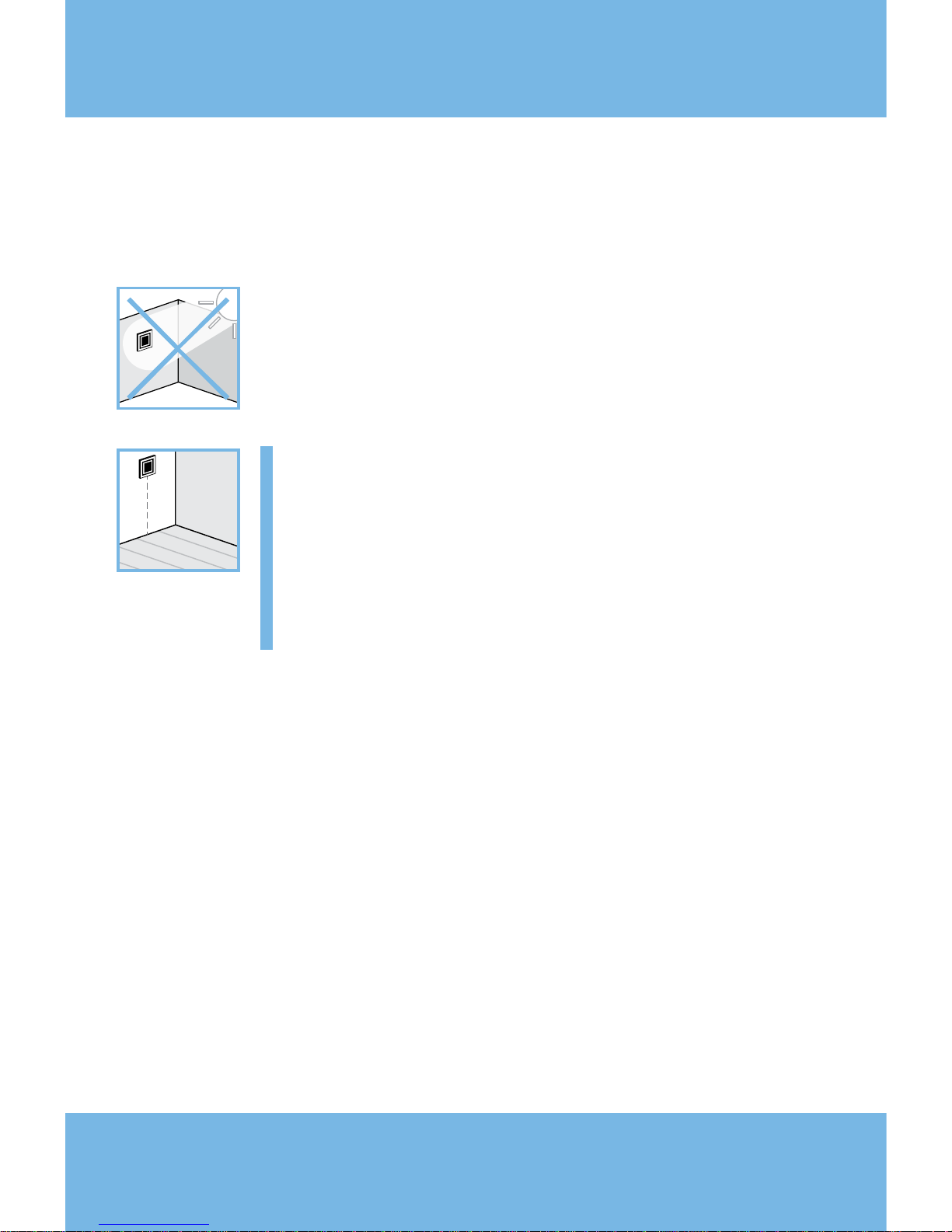
Please observe the placement guidelines below.
Place the thermostat at a suitable height on
the wall (typically 80–170cm from the floor).
The thermostat should not be placed in wet
rooms, place it in an adjacent room instead.
When installing the thermostat outside the
room it should be in ‘floor sensor only’ mode.
Always place the thermostat according to
local regulations on IP classes.
Do not place the thermostat on the inner side
of an exterior wall.
Always install the thermostat at least 50cm
from windows and doors.
Page 9
9
harmoni 50
Do not place the thermostat in a place that is
exposed to direct sunlight.
Important: A floor sensor enables a
more accurate temperature control and
is recommended in all floor heating
applications and is compulsory under
wooden floors to reduce the risk of
overheating the floor.
h Place the floor sensor in a conduit in an appropriate
place where it is not exposed to sunlight or draft from
door openings.
h Equally distant and >2cm from two heating cables.
h The conduit should be flush with the floor surface;
countersink the conduit if necessary.
h Route the conduit to the connection box.
h The bending radius of the conduit must be a minimum
of 50mm.
Page 10
10
installation guide
Mounting Instructions 2
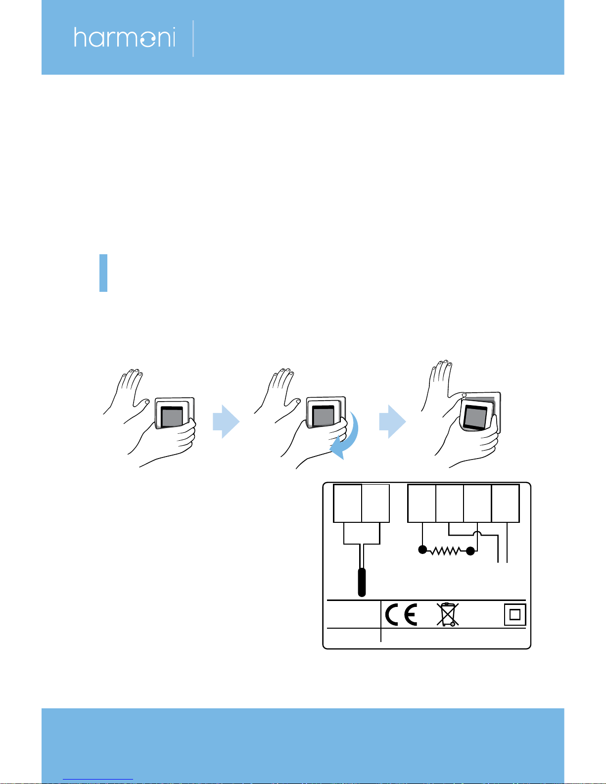
Follow the steps below to mount the thermostat.
1. Open the thermostat.
Important: Do NOT press on the display screen
when removing the front part.
Press your fingers under the side of the front part
and gently pull it away.
2. Connect the thermostat
according to the
connection diagram.
The screen of the heating
cable must be connected
to the earth conductor of
the power supply cable
by using a separate connector.
harmoni Standby maximum 0.4W
NT NL
NL
C
Maximum
Load 16 (1) A
Mains
220-240V–
50-60 Hz
Sensor
L
O
A
D
L
O
A
D
IP21
T30
Page 11
11
harmoni 50
Important: Always install the floor sensor in
a conduit in the floor.
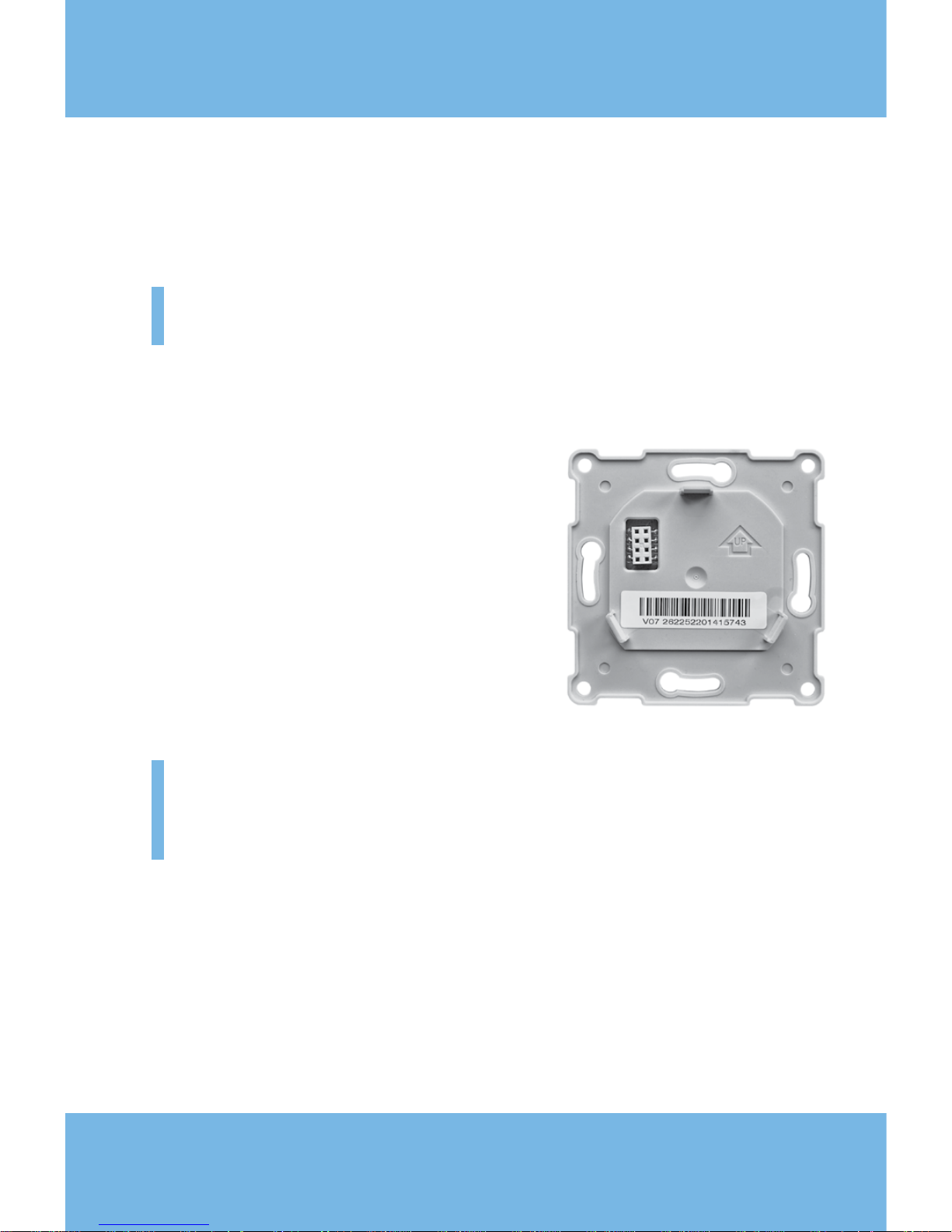
3. Mount and reassemble the thermostat.
h Fix the thermostat to a socket
or an exterior wall box using
the screw holes in each side
of the thermostat.
h Reattach the frame.
h Click the display module back
in place.
Important: Do NOT press on the display
screen when clicking the display module back
in place.
Initially, fully charge the thermostat battery using the
mains supply for 15 hours. The current time and day
is
then kept for 24 hours if mains supply is switched off.
All other settings are stored permanently.
Page 12
12
installation guide
Settings 3
Initial Settings 3.1
Initial settings must be specified when the unit is
activated for the first time.
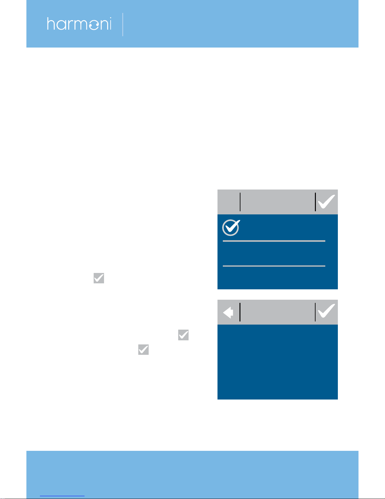
1. LANGUAGE. The language
is set to English by default.
2. SET TIME. Press the hour
numbers using the < and >
arrows to set the hour.
Press to confirm.
3. Press the minute numbers
using the < and > arrows to
set the minutes. Press to
confirm. Press again
to go to the SET DATE
screen.
SET TIME
14:56
LANGUAGE
English
Page 13
13
harmoni 50
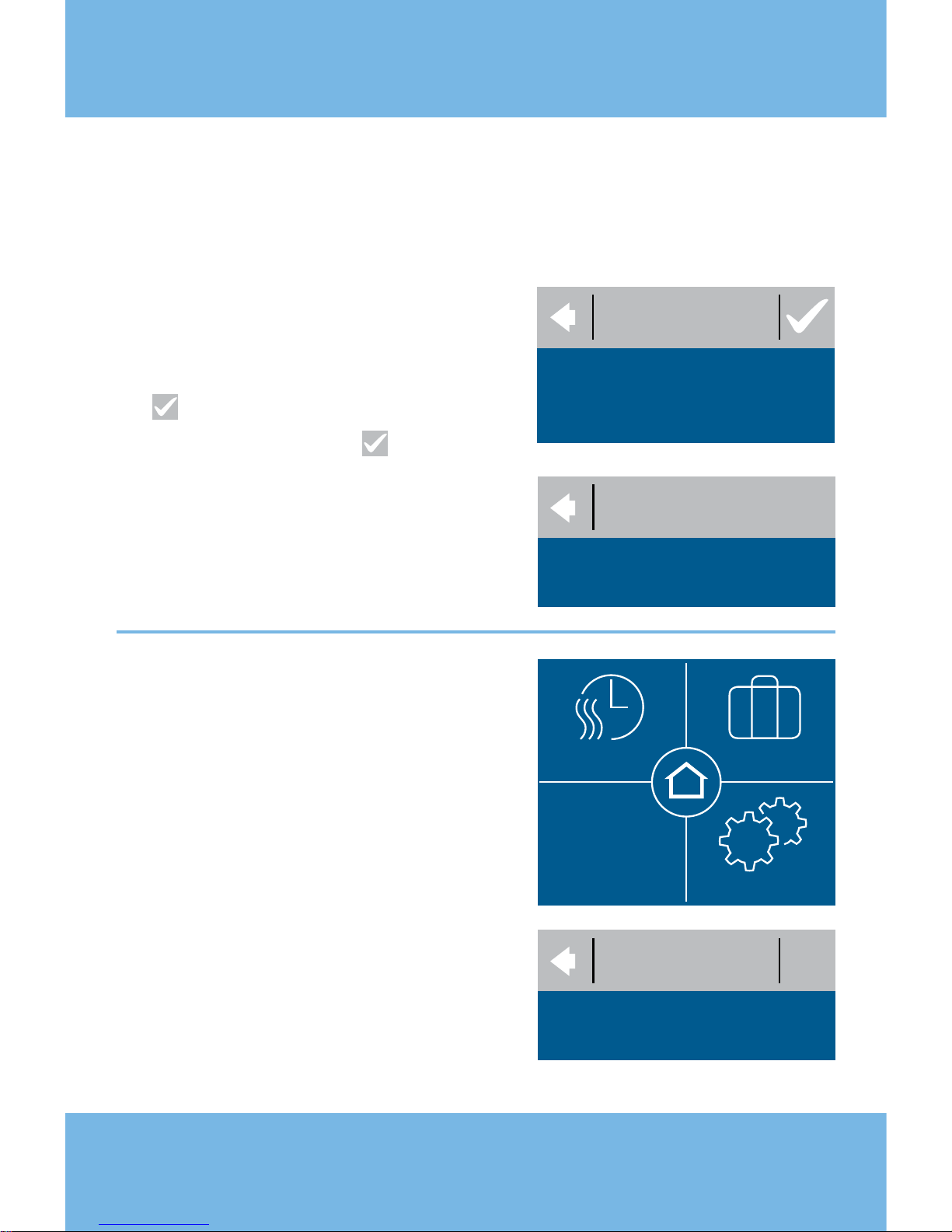
4. Press the day, month and
year to set the date using
the < and > arrows, pressing
to confirm. When the date
is correct, press on the
SET DATE screen to confirm.
5. Press SETUP WIZARD and
go to Step 6 on page 14.
Have you already set up
another thermostat?
If you have already
set one
thermostat, you can easily copy
the same settings to another
one (or more). Go to the original
thermostat and press
SETTINGS. Press INFO then
READ OUT. Write down the
generated code then go
directly
to Step 13 on page 16.
SET DATE
31:01:12
READ OUT
10B1-0F57-A845-41FE
TIME/DATE SETTINGS
TIMER AWAY
12:52
16.10.13
INSTALLATION
SETUP WIZARD
Page 14
14
installation guide
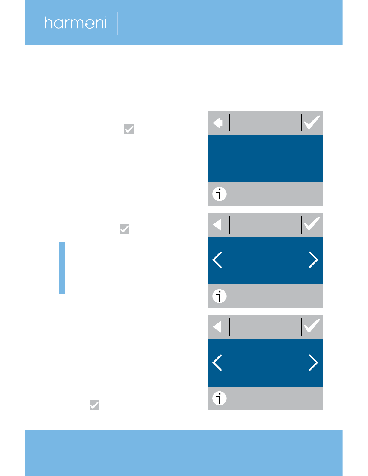
6. On the SETUP information
screen press to start.
7. CONTROL. Use the < and >
arrows to select whether
only a floor sensor or a
combination of room and
floor sensors should be
used. Press to confirm.
Note: A ‘room only’ option
may also be available.
See Maximum Floor
Temperature on page 20.
8. SENSOR TYPE. Use the
< and > arrows to select the
installed floor sensor type
(measured resistance &
corresponding temperature
are shown in brackets).
Press to confirm.
SENSOR TYPE
3/7
15K STANDARD
(14.5kΩ 25.18°)
SETUP
1/7
Initial Settings 3.1
WALK
THROUGH THE
FOLLOWING
STEPS.
CONTROL
2/7
ROOM +
FLOOR
Page 15
15
harmoni 50
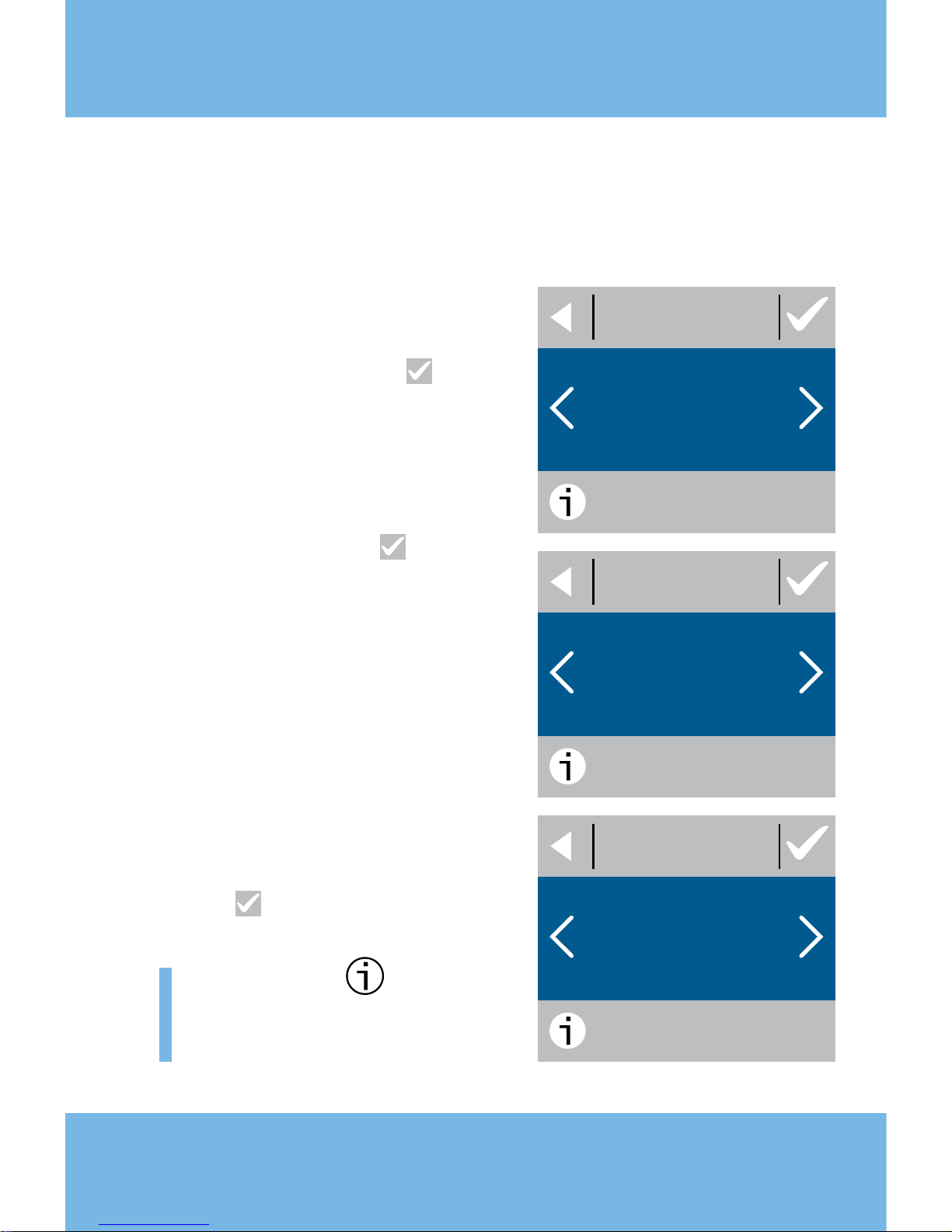
9. FLOORING. Use the
< and > arrows to select the
flooring type. Press to
confirm.
10.
ROOM TYPE. Use the
< and > arrows to select the
room type. Press to
confirm.
11.
OUTPUT [W]. Use the
< and > arrows to set the
approximate load of the
heating element. If an
external relay is used or the
installed output is unknown,
select the ‘--’ option.
Press to confirm.
Note: P
ress
for more
information about the
selected function.
FLOORING
4/7
TILES
OUTPUT [W]
6/7
450
ROOM TYPE
5/7
BATHROOM
Page 16
16
installation guide
Initial Settings 3.1
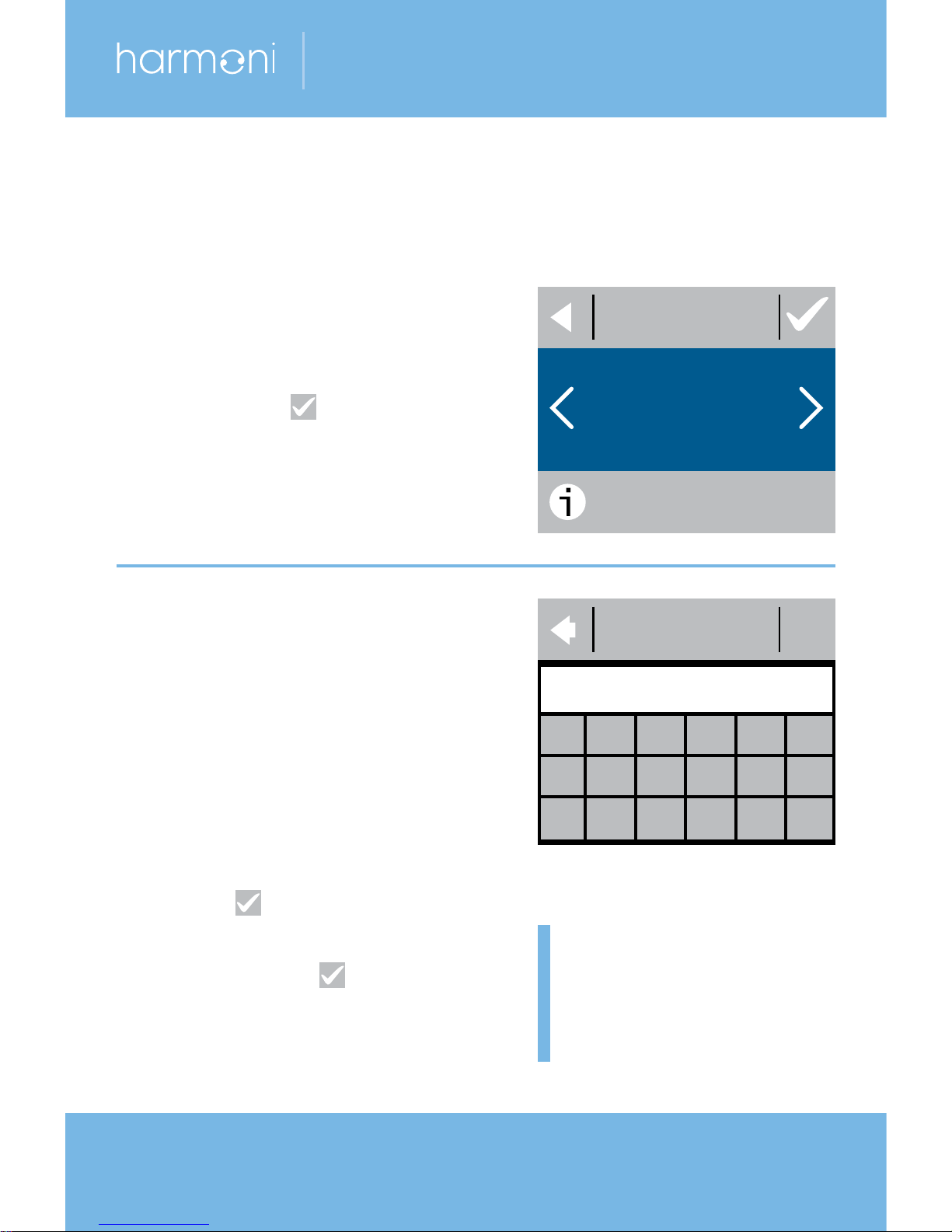
12.
TIMER. Use the < and >
arrows to select whether the
timer should be activated or
not. Press to confirm and
end the initial thermostat
setup. Skip Step 13
.
If you already have one
thermostat set up.
13.
Press SETTINGS then
INSTALLATION. Press
ENTER CODE.
Key in your generated code
(no spaces or hyphens).
Press to end the initial
thermostat setup. If no
check
mark ( ) appears,
the generated code is
incorrect.
TIMER
7/7
OFF
ENTER CODE
0 1 2 3 4 5
6 7 8 9 a b
c d e f clr del
Note: Go to page 13
for details on where
to find the generated
code.
Page 17

17
harmoni 50
Forecast 3.2
When Forecast is turned on, heating will start earlier so
the required temperature is reached at the specified time.
For example, if your comfort temperature is set to 22°C
and the timer is set to 6am, the temperature will be 22°C
at 6am. However, if Forecast is switched off, heating
won’t start until 6am and will take a while to reach 22°C.
The Forecast feature also optimises heating stop
when
switching from comfort to economy temperature.
How to turn the Forecast feature on and off.
21.5
menu
1. Touch the thermostat
display to activate it,
then press menu.
2. Press SETTINGS in the
bottom right corner of the
menu.
Press OPTIONS.
TIME/DATE SETTINGS
TIMER AWAY
12:52
16.10.13
Page 18
18
installation guide
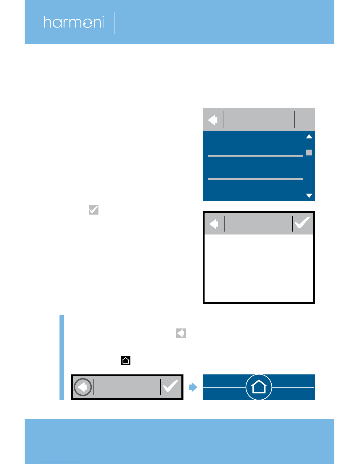
3. Press FORECAST.
4. Press ON to optimise
heating start/stop.
Or press OFF to simply let
the heating start/stop at
the specified time.
Press to confirm.
Note: To return to the normal temperature display,
press the back arrow ( ) in the upper left corner
of the screen until you get to the main menu. Press
the home ( ) symbol in the middle of the screen.
Forecast 3.2
FORECAST
ON / OFF
OPTIONS
SAFETY LOCK
FORECAST
DIM LEVEL
FORECAST
TIMER AWAY
Page 19
19
harmoni 50
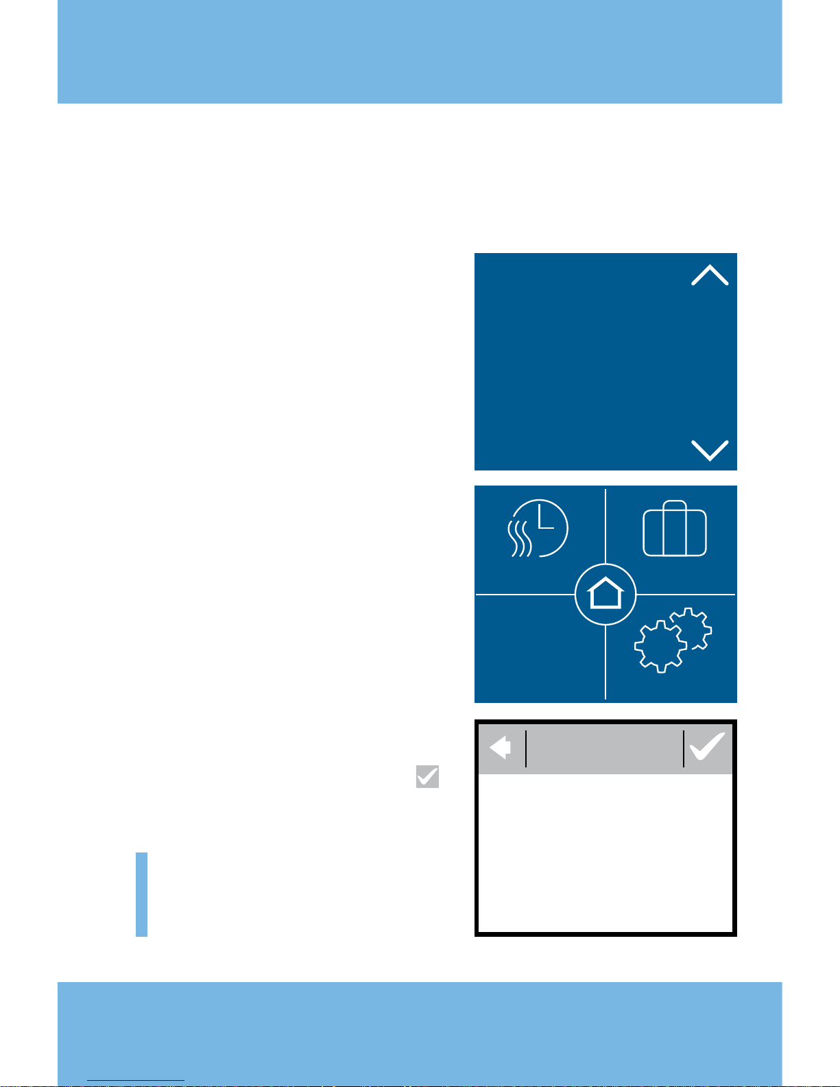
How to turn ‘window open
detection’ on or off.
1.
Touch the thermostat display
to activate it. Press menu.
2. Press SETTINGS in the
bottom right corner of the
menu. Press OPTIONS.
3. Press WINDOW OPEN.
Press ON to temporarily
turn off heating in case of
a sudden temperature drop
in the room or OFF to let
the thermostat heat up, also
during sudden temperature
drops in the room. Press
to confirm.
Note: To return to the
normal temperature display,
see note on page 18.
21.5
menu
TIME/DATE SETTINGS
TIMER AWAY
12:52
16.10.13
Window Open 3.3
WINDOW
ON / OFF
Page 20
20
installation guide
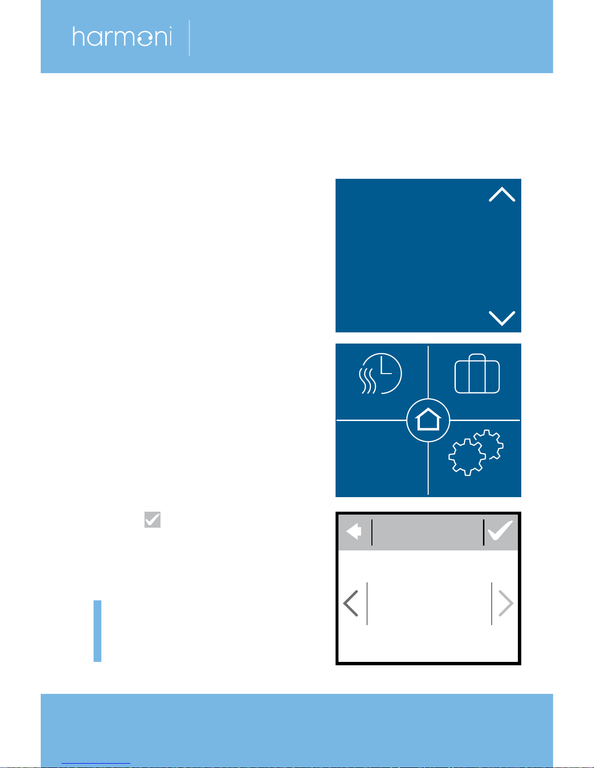
How to set the maximum
floor temperature.
1.
Touch the thermostat display
to activate it. Press menu.
2. Press SETTINGS in the
bottom right corner of
the menu. Press
INSTALLATIONS and
MANUAL SETUP.
3. Press MAX. FLOOR.
Use the < and > arrows
to set the allowed
maximum floor temperature.
Press to confirm.
Note: To return to the
normal temperature display,
see note on page 18.
Maximum Floor Temperature 3.4
21.5
menu
MAX. FLOOR
35.0
TIME/DATE SETTINGS
TIMER AWAY
12:52
16.10.13
Page 21
21
harmoni 50
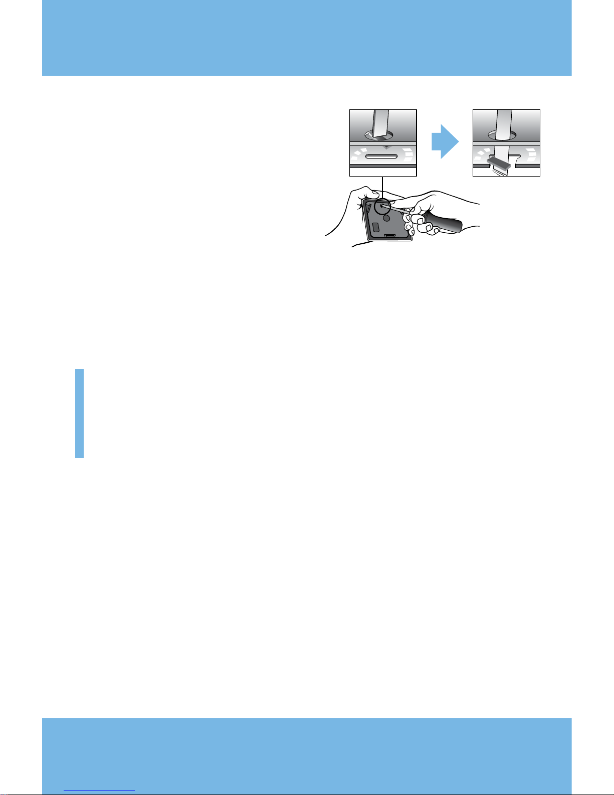
If you break the small plastic
seal on the back of the display
module (eg, using a
screwdriver), it's possible to set the maximum floor
temperature to 45°C. It would also be possible to use
only a room sensor. However, this isn't recommended
due to an increased risk of overheating the floor.
Important: When the thermostat is used to control a
floor heating element in connection with a wooden floor
or similar material, always use a floor sensor and never
set the maximum floor temperature to more than 35°C.
Note: Please contact the floor supplier before altering the
maximum floor temperature and be aware of the following:
h The floor temperature is measured where the sensor
is placed.
h The temperature at the bottom of a wooden floor can
be up to 10
°C
hotter than the top.
h Floor manufacturers often specify the maximum
temperature on the top surface of the floor.
Page 22

22
installation guide
Thermal
resistance
(m2K/W)
Examples of flooring Details Approx.
setting for
25°C floor
temperature
0.05 8mm HDF based
laminate
<
800
kg/m³
28°C
0.10 14mm beech parquet 650–800
kg/m³
31°C
0.13 22mm solid oak plank
>
800
kg/m³
32°C
<
0.17 Max. carpet thickness
suitable for floor heating
acc. to EN
1307
34°C
0.18 22mm solid fir planks 450–650
kg/m³
35°C
Maximum Floor Temperature 3.4
Page 23
23
harmoni 50
How to enable and disable
the timer.
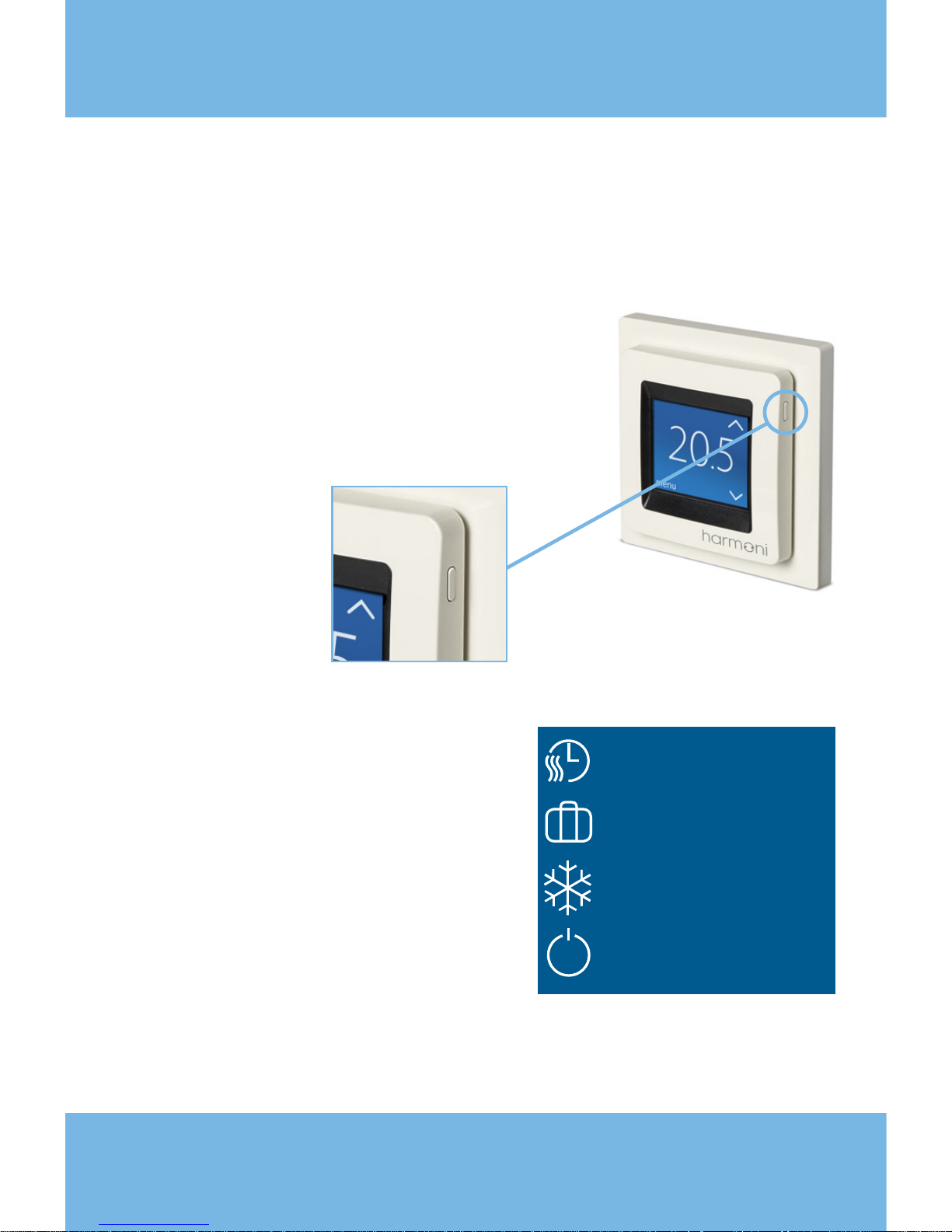
1.
Press the button on the side
of the thermostat
.
2. Press ENABLE TIMER to
turn the timer function on,
or DISABLE TIMER to turn
the timer function off.
Enable/Disable Timer 3.5
ENABLE TIMER
AWAY
FROST PROTECTION
POWER OFF
Page 24
24
installation guide
Symbols 4
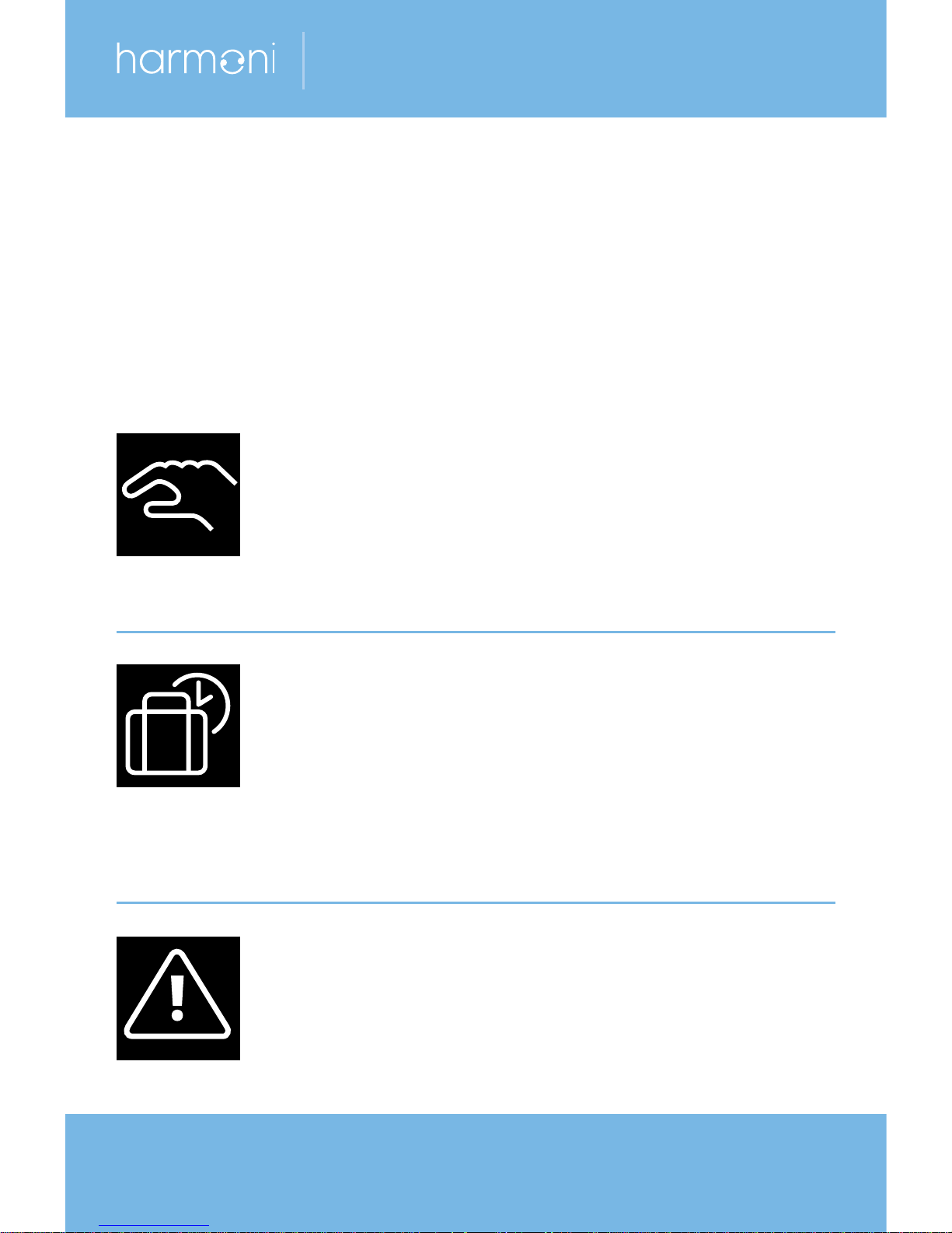
The symbols shown below may appear in the upper left
corner of the temperature display:
Symbol Meaning
The thermostat is in manual mode, ie, the
timer function is off. The timer lets you
automatically switch between economy
and comfort temperatures according to a
predefined schedule.
An away period has been planned. On the
date of departure, the away period starts at
00:00 and the specified away temperature
will be maintained 24 hours a day until the
date of return at 00:00. At this time the
normal temperature settings will resume.
An error has occurred. If you press the
warning symbol, more information on the
error will appear.
NL
C
Maximum
Load 16 (1) A
Mains
220-240V–
50-60 Hz
Sensor
L
O
A
D
L
O
A
D
IP21
T30
Page 25

25
harmoni 50
Warranty 6
The harmoni 50 thermostat
comes with a 5-year warranty as
standard.
Disposal Information 5
Page 26

26
installation guide
Warranty 6
Name .............................................................................
Address ..........................................................................
.......................................................................................
County ..................................... Postcode........................
Address ..........................................................................
Phone .............................................................................
Email ..............................................................................
Please note
In order to obtain the harmoni warranty, an authorised
electrician/installer must fill in the details below.
Electrician
Installation
/installer .......................................... date ....................
Thermostat Article
name ............................................. number ................
Stamp:
Page 27

27
harmoni 50
Notes
Page 28

installation guide
harmoni
Edison House
Edison Close
Ransomes Europark
Ipswich
Suffolk IP3 9GU
United Kingdom
T: 01473 559088
F: 01473 559076
E: [email protected]
www.harmonithermostat.co.uk
harmoni cannot accept any responsibility for any errors in catalogues, brochures and other printed material.
harmoni reserves the right to alter its products without notice. This also applies to products already on
order provided that such alterations can be made without subsequent changes to specifications already
agreed. All trademarks in this material are the property of harmoni. harmoni and the harmoni logotype are
trademarks of Edison House Trading Ltd. All rights reserved.
 Loading...