

Page 1
harman/kardon
TU 980 Service Manual
Page 1 of 32
PAGE 32-38 ADDED INFORMATION ABOUT NEW EUP-VERSION WITH STANDBY TRANSFORMER.
harman/kardon Service Manual
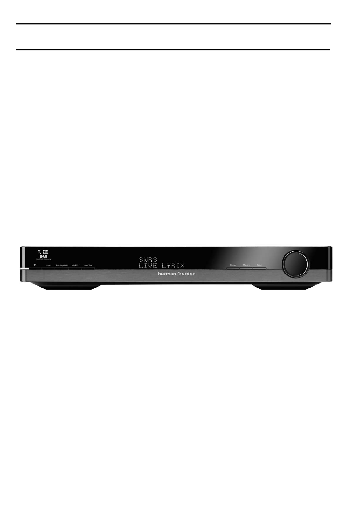
TU 980/230
FM/AM/Dual-band DAB Tuner with RDS
FRONT PANEL CONTROLS 2 EXPLODED VIEW AND PARTS 13
REAR PANEL CONNECTIONS 3 ELECTRICAL PARTS LIST 14
REMOTE CONTROL FUNCTIONS 4 SEMICONDUCTOR FUNCTION/PINOUTS 21
TROUBLESHOOTING GUIDE 5 PCB DRAWING 29
TECHNICAL SPECIFICATIONS 6 BLOCK DIAGRAM 30
PACKAGE LIST AND PARTS 11 WIRING DIAGRAM 31
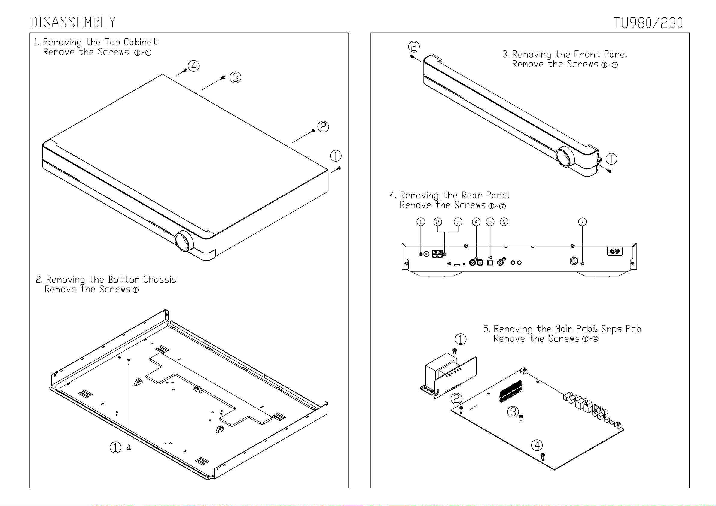
DISASSEMBLY 12
CONTENTS
SCHEMATIC DIAGRAM 32
Released EU2010 harman/kardon, Inc. Rev 1, 08/2012
250 Crossways Park Dr.
Woodbury, New York, 11797
Page 2
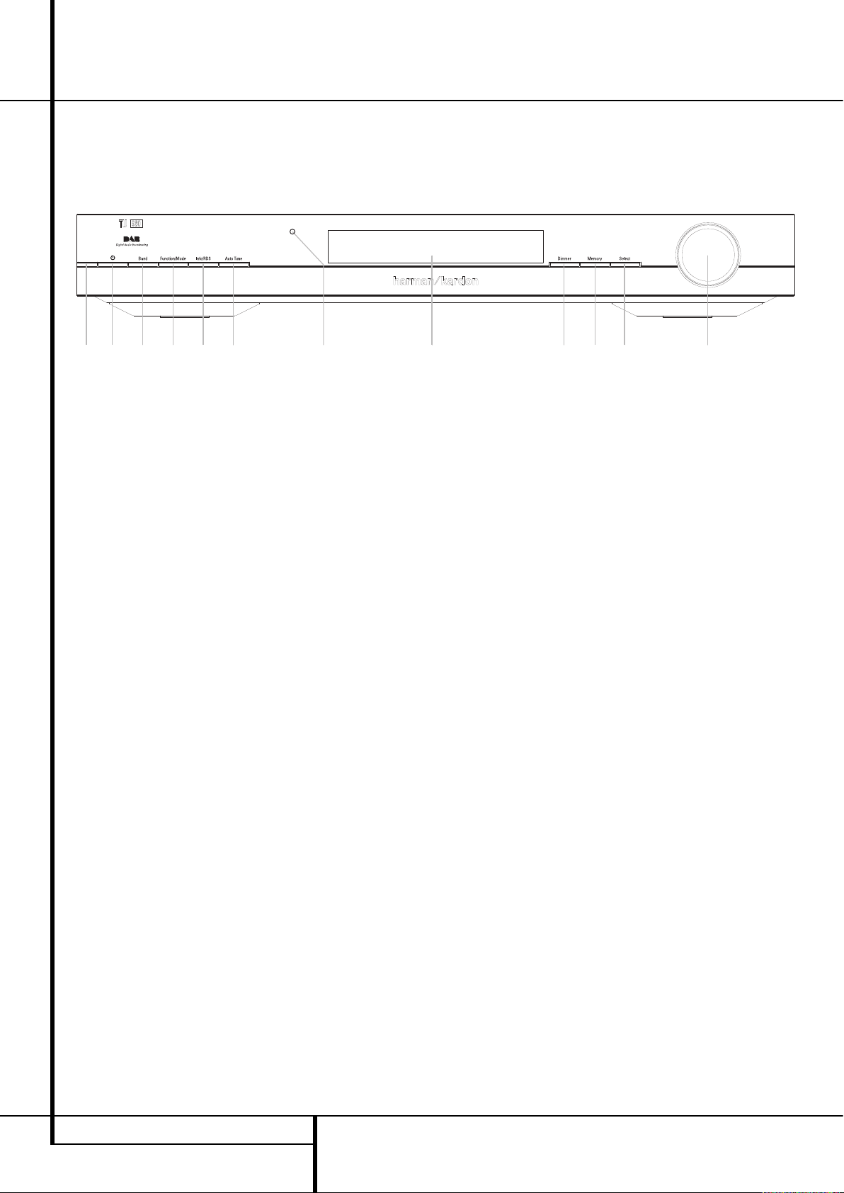
Power Indicator: This LED will illuminate in
amber when the unit is in the Standby mode to
signal that the unit is ready to be turned on.
When the unit is in operation, the indicator will
turn blue.
1
System Power Control: Press this button
to turn on the TU 980; press it again to turn the
unit off (to Standby). Note that the Power Indi-
cator
next to the switch will turn blue when
the unit is on.
2
Band Selector: Press this button to change
between the DAB, FM and AM frequency bands.
3
Function/FM Mode Selector: In DAB
mode, pressing this button will activate station
order, preset tune, Dynamic Rate Control or
manual tune features. In FM mode, press this
button to select the stereo or mono mode for
FM tuning. In the stereo mode, the word
STEREO
will be shown in the Information
Display
6
, and stereo reception will be
provided when stations are transmitting stereo
signals. In the mono mode, the left and right
signals from stereo broadcasts will be mixed
together and reproduced through all channels.
Select
MONO
for better reception of weak
signals.
4
Info/RDS Button: In DAB mode, pressing
this button will change the content of the lower
display line of the Information Display as shown
on page 9, as well as signal error rate and software version. In RDS mode, it will change
between the different RDS options.
5
Auto Tune Button: In DAB mode, press this
button to automatically scan all available
stations.
6
Information Display: This dual line display
delivers messages and status indications to help
you operate the tuner.
7
Dimmer: Press this button to dim the front
panel display. The first press of the button will
dim the displays to one-half normal brightness;
the next press will turn off the display. Press the
button again to turn the displays back to normal
brightness.
The display will return to normal brightness the
next time the unit is turned on.
8
Memory Button: Press this button to open
the memory position that stores a preset
location in the tuner. 99 DAB presets can be
stored, as well as 30 FM and 30 AM presets.
(See page 9 for more information on tuner
presets.)
9
Control Ring: Turn counterclockwise to
tune lower frequency stations and clockwise to
tune higher frequency stations. When a station
with a strong signal is tuned, the Information
Display
6
will read
TUNED
. Turn again to
tune to the next frequency increment in Manual
Tune Mode, or automatically to the next
station with a signal strong enough for
acceptable reception in Auto Tune Mode.
The ring also controls the parameters in the
different menus.
A Select: In FM or AM mode, press this
button to select Auto Tune, Manual Tune or
Preset Tune. In DAB mode, press this button to
select the displayed station.
B
Remote Sensor Window:The sensor
behind this window receives infrared signals
from the remote control. Aim the remote at this
area and do not block or cover it unless an
external remote sensor is installed.
4 FRONT PANEL CONTROLS
Front Panel Controls
1
2
3
4
5
6
7
8
9
A
B
Power Indicator
System Power Control
Band selector
Function/FM Mode Selector
Info/RDS Button
Auto Tune Button
Information Display
Dimmer
Memory
Control Ring
Select
Remote Control Sensor
harman/kardon
TU 980 Service Manual
Page 2 of 32
1
2
3
4
5
@
6
8
7
9A
Page 3
REAR PANEL CONNECTIONS 5
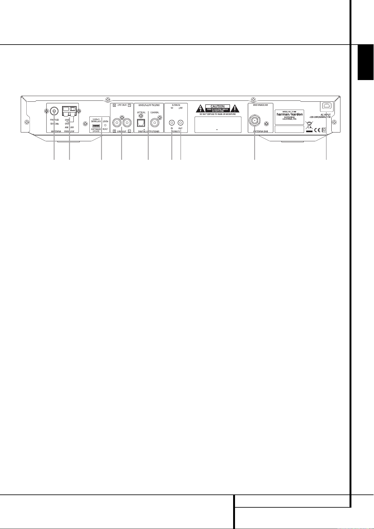
Rear Panel Connections
4
Optical and Coaxial Digital Outputs
FM Antenna
AM Antenna
Analog Audio Outputs
DAB Antenna
AC Power Cord
Remote Control Output
Remote Control Input
Software Update and Reset Button
Optical and Coaxial Digital Outputs:
Connect one of these jacks to the optical or
coaxial digital input of your pre amplifier or
integrated amplifier, if available.
Note that these digital outputs only contain the
digital signal from the DAB stations. For FM/AM
reception, you will have to connect the analog
outputs at all times.
FM Antenna: Connect an indoor or exter-
nal FM antenna to this terminal.
AM Antenna: Connect the AM loop
antenna supplied with the receiver to these
terminals. If an external AM antenna is used,
make connections to the AM and GND
terminals in accordance with the instructions
supplied with the antenna.
Analog Audio Outputs: Connect these
jacks to the tuner input of your pre amplifier or
integrated amplifier for analog audio playback.
Be certain to observe proper channel
connections using the color-coded cables and
connectors so that red connects right channels
and white connects left channels.
NOTE: Before making any audio connections,
unplug all components of your audio system
from their AC power outlets. To reduce the
possibility of hum or noise in your system, place
all audio interconnection cables away from both
AC power cords and speaker wires.
DAB Antenna: Connect a DAB antenna to
this terminal.
AC Power Cord: Connect this plug to an
AC outlet. If the outlet is controlled by a switch,
make certain that it is in the ON position.
Remote Control Output: Connect this
jack to the infrared (IR) input jack of another
compatible Harman Kardon remote controlled
product to have the built-in Remote Sensor on
the tuner provide IR signals to other compatible
products.
Remote Control Input: Connect the
output of a remote infrared sensor, or the
remote control output of another compatible
Harman Kardon product, to this jack. This will
enable the remote control to operate even when
the front panel Remote Sensor on the tuner is
blocked. This jack may also be used with
compatible IR remote control-based automation
systems.
Software Update and Reset Button
(for Service Stations Only): This specialized
connector may be used with your personal computer in case Harman Kardon offers a software
upgrade for the tuner at some time in the
future. The Reset Button is only used during a
software upgrade. A standard processor reset is
performed by pressing and holding the frontpanel Function/FM Mode Button.
ENGLISH
harman/kardon
TU 980 Service Manual
Page 3 of 32
2
1
8
3
0
7
6
5
Page 4
0
1
2
3
4
5
6
7
8
9
A
6 REMOTE CONTROL FUNCTIONS
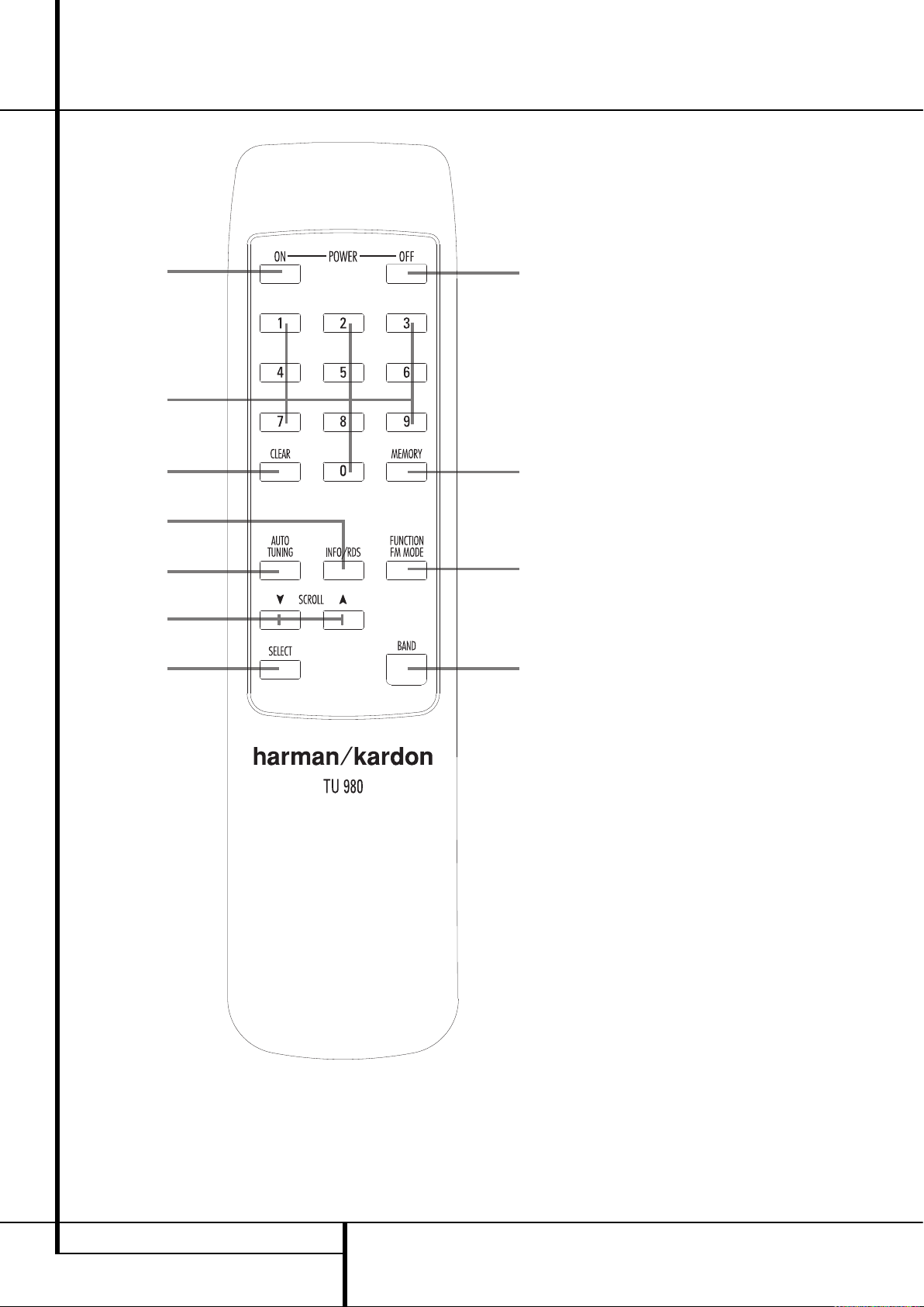
Remote Control Functions
Standby/Power On
Numeric Keys
Clear Button
Info/RDS Button
Auto Tuning Button
Scroll Button
Function/FM Mode Selector
Band Selector
Select Button
Memory Button
Standby/Power Off
0
Standby/Power On: Press this button to
turn on the TU 980. Note that the Power
Indicator
next to the switch will turn blue
when the unit is on.
1
Numeric Keys: These buttons serve as a
ten-button numeric keypad to enter tuner preset
positions or to tune stations directly.
2
Clear Button: Press this button to clear
presets from your station list.
3
Info/RDS Button: Pressing this button will
change the content of the lower display line of
the Information Display as well as signal error
rate and software version. (See page 9 for more
info).
4
Auto Tune Button: In DAB mode, press
this button to automatically scan all available
stations.
5
Scroll Buttons: Press L to tune lower
frequency stations and
K to tune higher
frequency stations. When a station with a strong
signal is tuned, the Information Display
6
will read
TUNED
. Press again briefly to tune to
the next frequency increment in Manual Tune
Mode, or keep pressed for automatic search for
the next station with a signal strong enough for
acceptable reception in Auto Tune Mode. These
buttons also control the parameters in the
different menus, like the Control Ring
9
on
the front panel.
6
Function/FM Mode Selector: In DAB
mode, pressing this button will activate station
order, preset tune, Dynamic Rate Control or
manual tune features. In FM mode, press this
button to select the stereo or mono mode for FM
tuning. In the stereo mode, the word
STEREO
will be shown in the Information Display6,
and stereo reception will be provided when
stations are transmitting stereo signals. In the
mono mode, the left and right signals from stereo
broadcasts will be mixed together and
reproduced through all channels. Select
MONO
for better reception of weak signals.
7
Band Selector: Press this button to change
between the DAB, FM and AM frequency bands.
8
Select: In FM or AM mode, press this
button to select Auto Tune, Manual Tune or Preset
Tune.
9
Memory Button: Press this button to open
the memory position that stores a preset location
in the tuner. 99 DAB presets can be stored, as
well as 30 FM and 30 AM presets. (See page 9
for more information on tuner presets.)
A
Standby/Power Off: Press this button to
turn the unit off (to Standby).
harman/kardon
TU 980 Service Manual
Page 4 of 32
0
1
2
3
4
5
8
A
9
6
7
Page 5

12 TROUBLESHOOTING GUIDE
Troubleshooting Guide
This unit is designed for trouble-free operation. Most problems users encounter are due to operating errors. If you have a problem, first check this list for a
possible solution. If the problem persists, consult your authorized Harman Kardon Service Center.
If the problem is... Make sure that the...
No lights appear when System Power button is pressed Unit is plugged into a live outlet.
Make sure the outlet is active.
No sound is heard Tune to an active station.
Check for correct amplifier settings.
Check the connections and wires.
Sound distorts, particularly in stereo mode. Use a more directional antenna.
Intermittent or continuous buzzing or hissing. Place the unit farther away from these appliances. Install noise filters on the appliances.
Display says 'No stations Available' Check that antenna is connected.
Ensure that DAB coverage exists in your area.
Display has gone blank or says 'service off air' This may occur if a broadcaster changes the label of a service or removes a label whilst you
are listening to it. Try to retune to this station, using the Autotune procedure.
harman/kardon
TU 980 Service Manual
Page 5 of 32
Page 6

TECHNICAL SPECIFICATIONS 13
Technical Specifications
FM Section
Frequency Range 87.50 MHz to 108.00 MHz (50 kHz steps)
Signal-to-Noise Ratio 65 dB (Mono) 60 dB (Stereo)
Presets 30
Section
Frequency Range 522 kHz to 1620 kHz (9 kHz steps)
Signal-to-Noise Ratio 35 dB
Presets 30
DAB Section
RF Section Band lll, 174 MHz - 240 MHz
Band L, 1452 MHz - 1492 MHz
Input: 50 Ohm, nominal
Max signal: -3 dBm typ
Sensitivity: -96 dBm typ
Adjacent Channel Rejection: 35dB typ
Display 2 line by 16 character DOT Matrix
Presets 99
Audio Output Stereo, 2.5V P-P
48 kHz sample rate 16 bit sample resolution
Optical S/PDIF IEC60958 Compliant
48 kHz sample rate 24 bit sample resolution
General
Power Requirement 220-230 V AC, 50/60 Hz
Power Consumption 11 W
3 W (standby)
Dimension (Max)
Width 442 mm
Height 63 mm
Depth 334 mm (350 mm with DAB antenna)
Weight 3.4 kg
Depth measurement includes knobs, buttons and terminal connections. Height measurement includes feet and chassis.
All features and specifications are subject to change without notice.
Harman Kardon and Power for the Digital Revolution are registered trademarks of Harman Kardon, Incorporated
ENGLISH
harman/kardon
TU 980 Service Manual
Page 6 of 32
Page 7
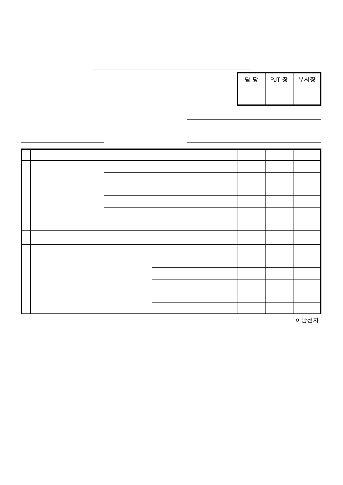
ELECTRICAL SPECIFICATION(BAND3 DAB)
(
harman/kardon
TU 980 Service Manual
Page 7 of 32
담 당 PJT 장 부서장
SAMPLING RATE : 48kHz
PAGE:1/4
MODEL : TU 980 STANDARD INPUT : -60dBm
DATE : AUDIO SIGNAL(L&R) :bit rate128kbit/s
POWER SUPPLY : 230V~240V , 50Hz AUDIO SIGNAL{L(R) only} :bit rate192kbit/s
NO DESCRIPTION CONDITION UNIT NOMINAL LIMIT L ch R ch
1 TUNING RANGE LOW MHz 174,928 -
HIGH MHz 239,200 -
2 INPUT SENSITIVITY dBm -98 -90
(T.H.D : 0.5%) dBm -98 -90
3 OUTPUT LEVEL V 2 2±0.1
4
S/N RATIO
IHF-A)
5 T.H.D (20 kHz L.P.F) % 0,02 0,05
5C 178.35MHz
11D 222.064MHz
13C 227.36MHz
11D 222.064MHz
11D 222.064MHz
11D 222.064MHz
dBm -98 -90
d B 95 80
6 STEREO SEPARATION 100Hz d B 80 70
( 20kHz L.P.F) 1kHz d B 80 70
11D 222.064MHz
10kHz d B 80 70
FREQUENCY RESPONSE
7 42Hz d B 0 -3
STANDARD(1kHz)
(20kHz L.P.F)
11D 222.064MHz
16kHz d B 0 -3
ADF-06-205(00)98.07.27 아남전자
Page 8
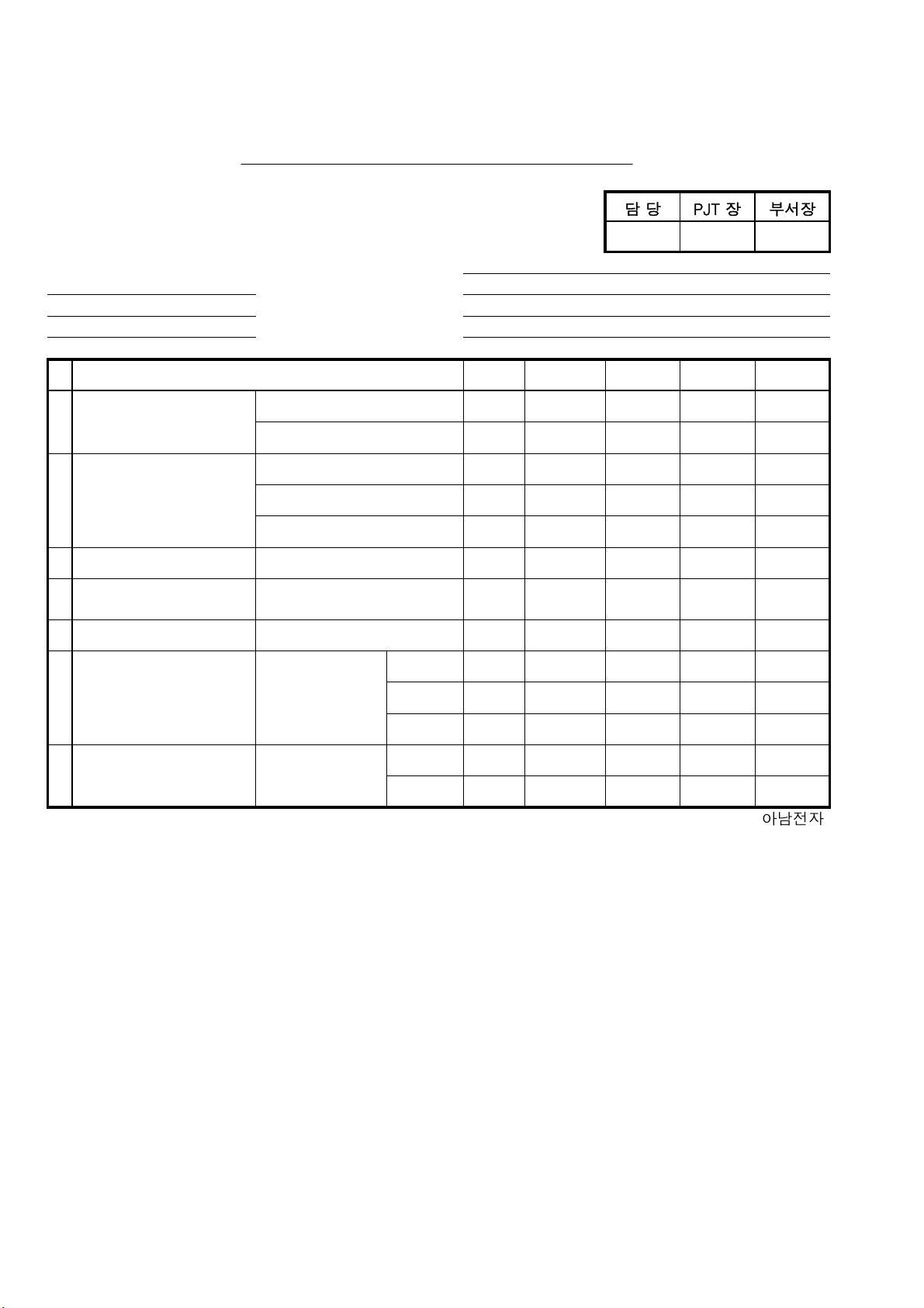
ELECTRICAL SPECIFICATION(L BAND DAB)
FREQUENCY
harman/kardon
TU 980 Service Manual
Page 8 of 32
담 당 PJT 장 부서장
SAMPLING RATE : 48kHz PAGE:2/4
MODEL : TU 980 STANDARD INPUT : -60dBm
DATE : AUDIO SIGNAL(L&R) :bit rate128kbit/s
POWER SUPPLY : 230V~240V , 50Hz AUDIO SIGNAL{L(R) only} :bit rate192kbit/s
NO DESCRIPTION CONDITION UNIT NOMINAL LIMIT L ch R ch
1 TUNING RANGE LOW MHz 1452,960
HIGH MHz 1490,624
2 INPUT SENSITIVITY dBm -95 -85
(T.H.D : 0.5%) dBm -95 -85
3 OUTPUT LEVEL V 2 2±0.1
4
S/N RATIO
(IHF-A)
5 T.H.D (20 kHz L.P.F) % 0,02 0,05
LC 1459.808MHz
LN 1475.216MHz
LX 1490.624MHz
LN 1475.216MHz
LN 1475.216MHz
LN 1475.216MHz
dBm -95 -85
d B 95 80
6 STEREO SEPARATION 100Hz d B 80 70
( 20kHz L.P.F) 1kHz d B 80 70
LN 1475.216MHz
10kHz d B 80 70
7 42Hz d B 0 -3
RESPONSE
STANDARD(1kHz)
LN 1475.216MHz
16kHz d B 0 -3
ADF-06-205(00)98.07.27 아남전자
Page 9
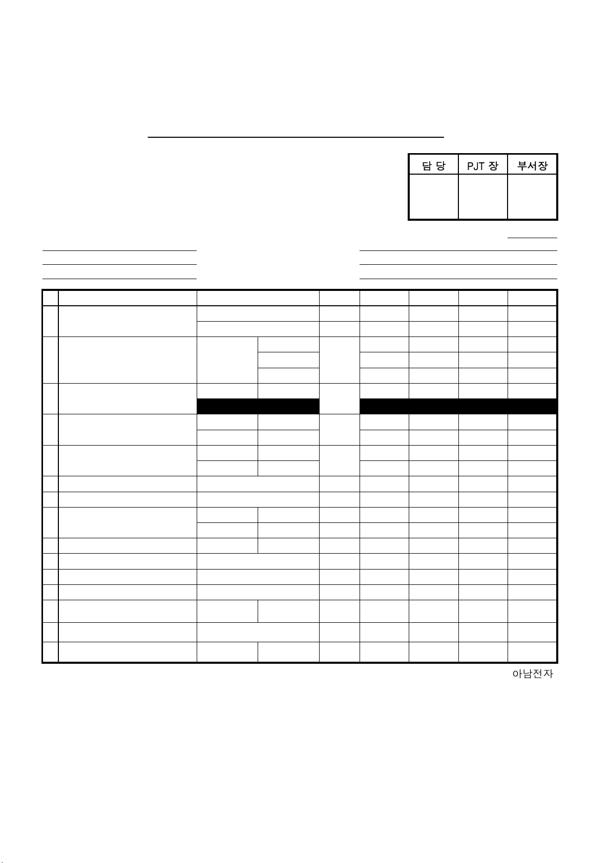
ELECTRICAL SPECIFICATION(TUNER/FM)
harman/kardon
TU 980 Service Manual
Page 9 of 32
담 당 PJT 장 부서장
PAGE:3/4
MODEL : TU 980 STANDARD INPUT : 60dB㎶ 400Hz
DATE : MOD : MONO 40kHz (DEV) --- 53.5%
POWER SUPPLY : 230V~240V , 50Hz : STEREO Main 40kHz Pilot 7.5kHz
※ USE 20KHz L.P.F
NO DESCRIPTION REMARK UNIT NOMINAL LIMIT L ch R ch
1 TUNING RANGE LOW MHz 87,50
HIGH MHz 108,00
USABLE SENSITIVITY MONO 90.10 MHz d B 8 15
2 ( S/N 30dB ) 75 Ω 100.10 MHz ( EMF ) 8 15
106.10 MHz 8 15
3 50dB QUIETING 100.10 MHz MONO d B 21 28
SENSITIVITY ( EMF )
4 S/N RATIO 100.10 MHz MONO d B 70 60
( L.P.F ) STEREO 60 50
5 T.H.D ( 400Hz ) 100.10MHz MONO % 0,3 1
( L.P.F ) STEREO 0,5 1,2
7 IF REJECTION (10.7MHz) 100.10 MHz d B 45 35
8 IMAGE REJECTION 106.10 MHz d B 40 30
10 FREQUENCY RESPONSE 100.10MHz LOW Hz 20 50
50 ㎲ (-3 d B) HIGH kHz 15 12
11 STEREO SEPARATION 100.10MHz 1kHz d B 35 25
12 ST. IND. LIGHT SENSI. 100.10MHz d B 29 25~35
13 TUNED IND. LIGHT SENS. 100.10MHz d B 29 25~35
14 AUTO STOP LEVEL 100.10MHz d B 29 25~35
17 RDS IND. LIGHT SENS. 100.10MHz d B 29 25~35
18 STRONG SIGNAL (120dBuV) 100.10MHz T.H.D % 1,5 3
ADF-06-205(00)98.07.27 아남전자
100.10MHz MONO VOUTPUT LEVEL15 1 1±0.2
Page 10
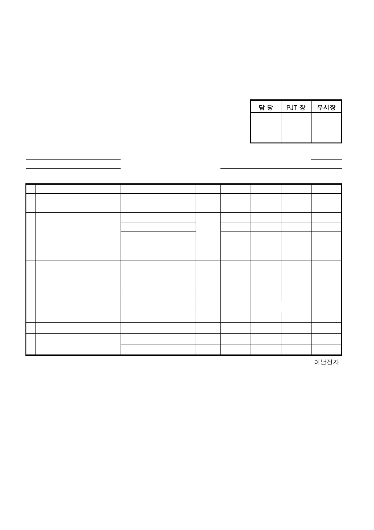
ELECTRICAL SPECIFICATION(TUNER/AM)
0
harman/kardon
TU 980 Service Manual
Page 10 of 32
담 당 PJT 장 부서장
MODEL : TU 980
PAGE:4/4
DATE : STANDARD INPUT : 74dB㎶ 400Hz
POWER SUPPLY : 230V~240V , 50Hz MOD : MONO 30 %
※USE 20KHz L.P.F
NO DESCRIPTION REMARK UNIT NOMINAL LIMIT L ch R ch
1 TUNING RANGE LOW kHz 522
HIGH kHz 1620
USABLE SENSITIVITY 612 kHz d B 60 70
2 ( S/N 20dB ) 990 kHz ( EMF ) 60 70
1503 kHz 60 70
3
4
35 30S/N RATIO 990 kHz MONO d B
1,5 3T.H.D ( 400Hz ) 990 kHz MONO %
6 IF REJECTION (450kHz) 990 kHz d B 35 30
7 IMAGE REJECTION 990 kHz d B 35 28
8 OUTPUT LEVEL 990kHz m V 360
60+80/-4
9 TUNED IND. LIGHT SENS. 990 kHz d B 60 50~70
10 AUTO STOP LEVEL 990 kHz d B 60 50~70
11 FREQUENCY RESPONSE 990 kHz LOW Hz 60 100
(-6dB) HIGH kHz 2,2 2
ADF-06-205(00)98.07.15 아남전자
Page 11
harman/kardon
TU 980 Service Manual
Page 11 of 32
Page 12
harman/kardon
TU 980 Service Manual
Page 12 of 32
Page 13

harman/kardon
TU 980 Service Manual
Page 13 of 32
Page 14

TU 980 BOM LIST
harman/kardon
TU 980 Service Manual
Page 14 of 32
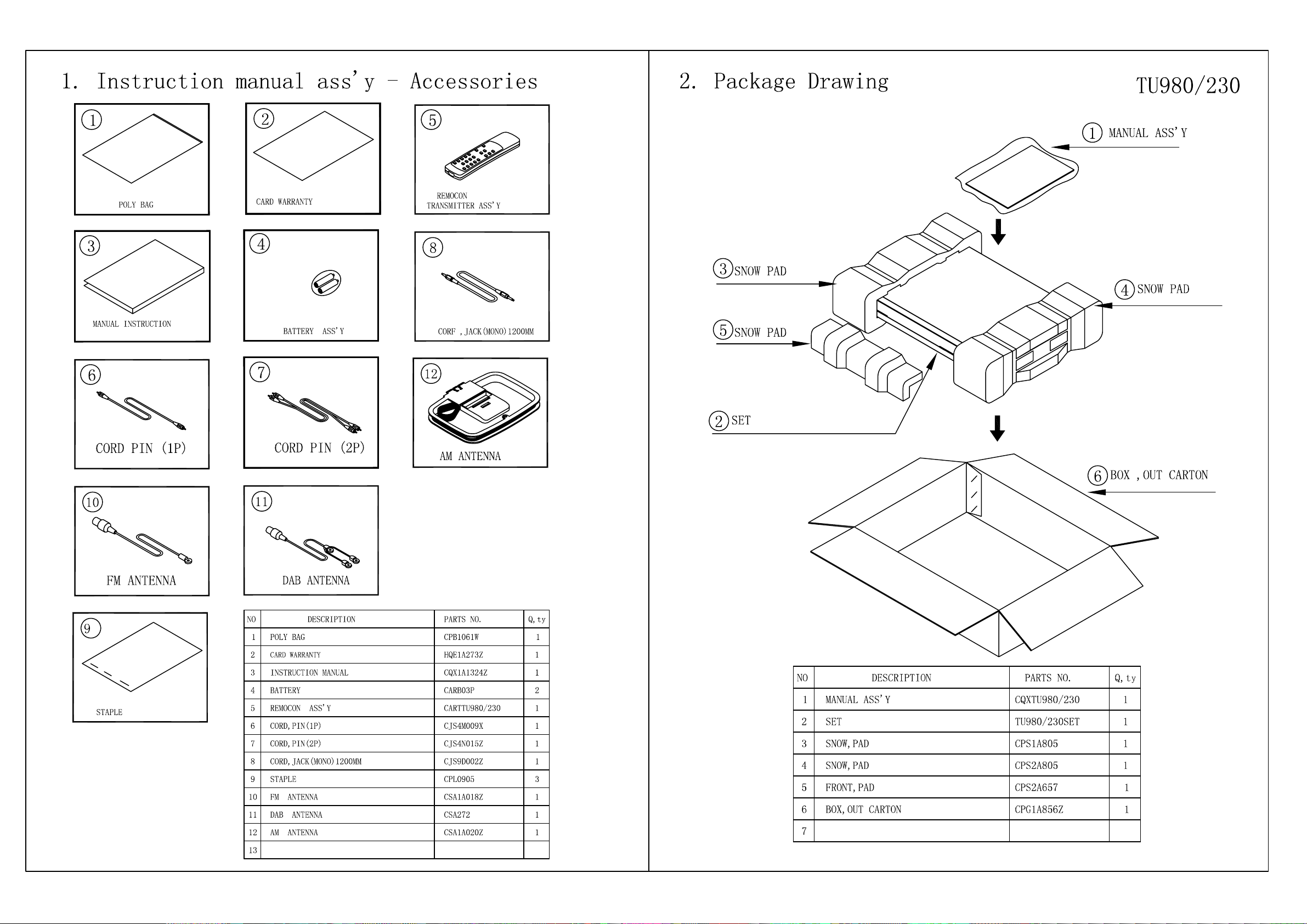
Level Ref# Component Description Drawing No REQ-Qty
1 CHE154 CLAMPER , ARM 0,12
1 CPG1A856Z BOX , OUT CARTON TU980/230 1
1 CPS1A805 PAD , SNOW TU980/230 1
1 CPS2A657 PAD , SNOW FRONT TU980 1
1 CPS2A805 PAD , SNOW TU980 1
1 CQB1A549Y LABEL , ATTENTION DVD48 1
1 CQB1A551Z LABEL , BAR CODE 3
1 CQB1A622 LABEL , SERIAL NO 1
1 CQB1A644Z LABEL , ORIGIN 1
1 CQB1A876Z LABEL , COUNTRY DVD29/230 2
1 CQS1A001 RIBON , BAR CODE SONY(TR-4070) 0,015
1 CQXTU980/230 INSTRUCTION MANUAL ASS'Y 1
0,2 CABR03P BATTERY (SIZE 'AAA') 2PCS IN 1PACK 2
0,2 CARTTU980 REMOCON TRANSMITTER ASS'Y 1
0,2 CJS4M009X CORD, PIN CORD, PIN 1
0,2 CJS4N015Z CORD , PIN 1
0,2 CJS9D002Z CORD , JACK(MONO) 1200MM 1
0,2 CPB1061W BAG , POLY(ENGLISH/FRANCH) FRANCE LANGUAGE ADDED 1
0,2 CPL0905 STAPLE 3
0,2 CQX1A1324Z MANUAL , INSTRUCTION TU980/230 1
0,2 CSA1A018Z FM 1 POLE ANT 1
0,2 CSA1A020Z ANT , AM LOOP 1
0,2 CSA272 ANT , DAB T T17020N 1
0,2 HQE1A273Z HARMAN IMAGE BROCHURES 1
0,2 CGB1A199Z BADGE , TOP TU980/230 1
0,2 CGWTU980/230 FRONT PANEL ASS'Y 1
..3 CBN1A218ZA TU980 TUNING KNOB ASS'Y 1
...4 CBN1A218 KNOB , TUNING TU980/230
...4 CGR1A444MBC63 ORNAMENT , TUNING TU980/230
...4 CGU1A414Z WINDOW , TUNING TU980/230
..3 CGW1A446ZA TU980 FRONT PANEL ASS'Y 1
...4 CBT1A1063 KNOB , FUNCTION TU980/230 1
...4 CGB1A158Y BADGE , FRONT HARMAN/KARDON 1
...4 CGB1A200Z BADGE , MODEL TU980/230 1
...4 CGL1A269 INDICATOR , POWER TU980/230 1
...4 CGU1A415A25Z WINDOW , FIP TU980/230 1
...4 CGW1A446R4B24 PANEL , FRONT TU980/230 1
...4 CGX1A398C66 ORNAMENT , AL PANEL TU980/230 1
...4 CGX1A399 SHEET , POWER TU980/230 1
...4 CMC1A341 PLATE , EARTH DMC250 2
...4 CMZ1A130Z FILTER , FIP TU980/230 1
..3 CHS1A032 TAPE , HEMELON 2
..3 CTB3+10JR SCREW 7
0,2 CHG1A305 CUSHION , SUPPORT 2
0,2 CKC1A183B33 CABINET , TOP TU980/230 1
0,2 CTB3+8JFZR SCREW 4
0,2 CUATU980/230 BOTTOM CHASSIS ASS'Y 1
..3 CHD1A023R SCREW , SPECIAL 1
..3 CHG1A104 CUSHION , EVA H=9.5(15X20) 1
..3 CHG3A104 CUSHION , EVA 1
..3 CHR301 CLAMPER 4
..3 CJA2B043ZA CORD , POWER(EUR) QDR-7100CC 1
..3 CKC1A183ZA TU980 TOP CABIET ASS'Y 1
...4 CGB1A199Z BADGE , TOP TU980/230
...4 CKC1A183B33 CABINET , TOP TU980/230
..3 CKF1A380Z PANEL , REAR TU980/230 1
..3 CKL1A097ZA TU980 FOOT ASS'Y 4
...4 CHG1A373 CUSHION , FOOT AVR350
...4 CKL1A097 FOOT , TU980/230
..3 CMH1A226 SUPPORT , PCB 2
..3 CNE1A009 NUT, DAB M3/8X32 1
..3 CNVFS2022V131C MODULE , DUAL DAB FS2022-0101-0005 1
Page 15

Level Ref# Component Description Drawing No REQ-Qty
harman/kardon
TU 980 Service Manual
Page 15 of 32
..3 CNVMB114MA18L TUNER MODULE(EUR) 1
..3 CNW1A038 WASHER 9.5X15 1
..3 COP12054B TU980 PCB ASS'Y 1
....5 CUP12054Z PCB , DAB TU980 (330X247, FR-1) 1
....5 C101 CCEA1CH471T CAP , ELECT 470UF 16V 1
....5 C104 CCFT1H223ZF CAP , CERAMIC 0.022UF 50V Z 1
....5 C203 CCEA1AH471T CAP , ELECT 470UF 10V 1
....5 C204 CCFT1H104ZF CAP , SEMICONDUCTOR 0.1UF 50V Z 1
....5 C205 CCEA1HH4R7T CAP , ELECT 4.7UF 50V 1
....5 C206 CCCT1H220JC CAP , CERAMIC 22PF 50V J 1
....5 C207 CCFT1H223ZF CAP , CERAMIC 0.022UF 50V Z 1
....5 C208 CCEA1CH101T CAP , ELECT 100UF 16V 1
....5 C209 CCEA1HH4R7T CAP , ELECT 4.7UF 50V 1
....5 C210 CCFT1H223ZF CAP , CERAMIC 0.022UF 50V Z 1
....5 C211 CCEA1CH101T CAP , ELECT 100UF 16V 1
....5 C212 CCEA1HH4R7T CAP , ELECT 4.7UF 50V 1
....5 C213 CCCT1H220JC CAP , CERAMIC 22PF 50V J 1
....5 C214 CCFT1H223ZF CAP , CERAMIC 0.022UF 50V Z 1
....5 C215 CCEA1CH101T CAP , ELECT 100UF 16V 1
....5 C216 CCEA1HH4R7T CAP , ELECT 4.7UF 50V 1
....5 C217 CCEA1CH101T CAP , ELECT 100UF 16V 1
....5 C218 CCFT1H223ZF CAP , CERAMIC 0.022UF 50V Z 1
....5 C219 CCEA1HH4R7T CAP , ELECT
4.7UF 50V 1
....5 C220 CCEA1HH4R7T CAP , ELECT 4.7UF 50V 1
....5 C221 HCQI1H152JZT CAP , MYLAR 1500PF 50V J 1
....5 C222 HCQI1H152JZT CAP , MYLAR 1500PF 50V J 1
....5 C223 CCEA1HH4R7T CAP , ELECT 4.7UF 50V 1
....5 C224 CCEA1HH4R7T CAP , ELECT 4.7UF 50V 1
....5 C225 CCFT1H103ZF CAP , CERAMIC 0.01UF 50V Z 1
....5 C228 CCEA1HH4R7T CAP , ELECT 4.7UF 50V 1
....5 C229 CCEA1CH101T CAP , ELECT 100UF 16V 1
....5 C230 CCEA1HH470T CAP , ELECT 47UF 50V 1
....5 C231 CCFT1H104ZF CAP , SEMICONDUCTOR 0.1UF 50V Z 1
....5 C234 CCCT1H330JC CAP , CERAMIC 33PF 50V J 1
....5 C235 CCEA1CH101T CAP , ELECT 100UF 16V 1
....5 C236 CCFT1H223ZF CAP , CERAMIC 0.022UF 50V Z 1
....5 C237 CCEA1CH101T CAP , ELECT 100UF 16V 1
....5 C702 CCBS1H330JT CAP , CERAMIC(33PF/50V) CH UP025SL330J-A-B Z 1
....5 C703 CCBS1H330JT CAP , CERAMIC(33PF/50V) CH UP025SL330J-A-B Z 1
....5 C704 CCFT1H223ZF CAP , CERAMIC 0.022UF 50V Z 1
....5 C705 CCKT1H221KB CAP , CERAMIC 220PF 50V K 1
....5 C706 CCKT1H221KB CAP , CERAMIC 220PF 50V K 1
....5 C707 CCEA1CH101T CAP , ELECT 100UF 16V 1
....5 C708 CCFT1H223ZF CAP , CERAMIC 0.022UF 50V Z 1
....5 C716 CCEA1AH471T CAP , ELECT 470UF 10V 1
....5 C717 CCFT1H223ZF CAP , CERAMIC 0.022UF 50V Z 1
....5 C718 CCKT1H101KB CAP , CERAMIC 100PF 50V K 1
....5 C719 CCKT1H101KB CAP , CERAMIC 100PF 50V K 1
....5 C720 CCKT1H101KB CAP , CERAMIC 100PF 50V K 1
....5 C722 CCKT1H101KB CAP , CERAMIC 100PF 50V K 1
....5 C723 CCKT1H101KB CAP , CERAMIC 100PF 50V K 1
....5 C727 CCFT1H223ZF CAP , CERAMIC 0.022UF 50V Z 1
....5 C728 CCFT1H223ZF CAP , CERAMIC 0.022UF 50V Z 1
....5 C729 CCEA1CH101T CAP , ELECT 100UF 16V 1
....5 C730 CCFT1H223ZF CAP , CERAMIC 0.022UF 50V Z 1
....5 C731 CCEA1CH101T CAP , ELECT 100UF 16V 1
....5 C732 CCKT1H101KB CAP , CERAMIC 100PF 50V K 1
....5 C733 CCBS1H104ZFT CAP , CERAMIC 0.1UF 50V Z 1
....5 C734 CCBS1H102KBT CAP , CERAMIC(1000PF/50V) CH UP025 B102K-A-B Z 1
....5 C735 CCBS1H102KBT CAP , CERAMIC(1000PF/50V) CH UP025 B102K-A-B Z 1
....5 C736 HCBS1H222KBT CAP , CERAMIC 2200PF 50V KB 1
....5 C737 CCBS1H104ZFT CAP , CERAMIC 0.1UF 50V Z 1
....5 C738 CCBS1H390JT CAP , CERAMIC(39PF/50V) CH UP025SL390J-A-B Z 1
....5 C739 CCBS1E103ZFT CAP , CERAMIC(10000PF/25V) CH TP025 F103Z-A-B J 1
Page 16

Level Ref# Component Description Drawing No REQ-Qty
harman/kardon
TU 980 Service Manual
Page 16 of 32
....5 C740 CCBS1E103ZFT CAP , CERAMIC(10000PF/25V) CH TP025 F103Z-A-B J 1
....5 C741 CCBS1E103ZFT CAP , CERAMIC(10000PF/25V) CH TP025 F103Z-A-B J 1
....5 C742 CCBS1E103ZFT CAP , CERAMIC(10000PF/25V) CH TP025 F103Z-A-B J 1
....5 C743 CCBS1E103ZFT CAP , CERAMIC(10000PF/25V) CH TP025 F103Z-A-B J 1
....5 C744 CCFT1H103ZF CAP , CERAMIC 0.01UF 50V Z 1
....5 C745 CCEA1HH220T CAP , ELECT 22UF 50V 1
....5 C746 CCFT1H103ZF CAP , CERAMIC 0.01UF 50V Z 1
....5 C747 CCBS1H104ZFT CAP , CERAMIC 0.1UF 50V Z 1
....5 C749 CCBS1H104ZFT CAP , CERAMIC 0.1UF 50V Z 1
....5 C751 CCEA1AKS221T CAP , ELECT 220UF 10V 1
....5 C752 CCBS1E103ZFT CAP , CERAMIC(10000PF/25V) CH TP025 F103Z-A-B J 1
....5 C754 CCEA1HH470T CAP , ELECT 47UF 50V 1
....5 C755 CCEA1CKS100T CAP , ELECT 10UF 16V 1
....5 C901 CCFT1H223ZF CAP , CERAMIC 0.022UF 50V Z 1
....5 C902 CCFT1H223ZF CAP , CERAMIC 0.022UF 50V Z 1
....5 C903 CCFT1H223ZF CAP , CERAMIC 0.022UF 50V Z 1
....5 C904 CCFT1H223ZF CAP , CERAMIC 0.022UF 50V Z 1
....5 C905 CCEA1HH220T CAP , ELECT 22UF 50V 1
....5 C906 CCFT1H223ZF CAP , CERAMIC 0.022UF 50V Z 1
....5 C908 CCEA1CH101T CAP , ELECT 100UF 16V 1
....5 C909 CCFT1H223ZF CAP , CERAMIC 0.022UF 50V Z 1
....5 C910 CCEA1CH101T
CAP , ELECT 100UF 16V 1
....5 C911 CCFT1H223ZF CAP , CERAMIC 0.022UF 50V Z 1
....5 C914 CCEA1AH471T CAP , ELECT 470UF 10V 1
....5 C915 CCFT1H223ZF CAP , CERAMIC 0.022UF 50V Z 1
....5 C916 CCEA1CH101T CAP , ELECT 100UF 16V 1
....5 C917 CCFT1H223ZF CAP , CERAMIC 0.022UF 50V Z 1
....5 C918 CCEA1CH101T CAP , ELECT 100UF 16V 1
....5 C919 CCFT1H223ZF CAP , CERAMIC 0.022UF 50V Z 1
....5 C920 CCEA1CH101T CAP , ELECT 100UF 16V 1
....5 C921 CCFT1H223ZF CAP , CERAMIC 0.022UF 50V Z 1
....5 C922 CCEA1CH101T CAP , ELECT 100UF 16V 1
....5 C923 CCFT1H223ZF CAP , CERAMIC 0.022UF 50V Z 1
....5 C924 CCEA1CH471T CAP , ELECT 470UF 16V 1
....5 C925 CCFT1H223ZF CAP , CERAMIC 0.022UF 50V Z 1
....5 C926 CCEA1CH101T CAP , ELECT 100UF 16V 1
....5 C927 CCFT1H223ZF CAP , CERAMIC 0.022UF 50V Z 1
....5 C928 CCEA1HH470T CAP , ELECT 47UF 50V 1
....5 C929 CCFT1H223ZF CAP , CERAMIC 0.022UF 50V Z 1
....5 D201 CVD1SS133MT DIODE 1SS133 1
....5 D202 CVD1SS133MT DIODE 1SS133 1
....5 D221 CVD1N4003ST DIODE , RECT 1N4003 1
....5 D702 CVD1SS133MT DIODE 1SS133 1
....5 D704 CVD1SS133MT DIODE 1SS133
....5 D706 CVD1SS133MT DIODE 1SS133 1
....5 D708 CVD1SS133MT DIODE 1SS133 1
....5 D712 CVDZJ4.3BT DIODE , ZENER ZJ4.3B 1/2W 1
....5 D713 CVDZJ4.3BT DIODE , ZENER ZJ4.3B 1/2W 1
....5 D715 CVDZJ20BT DIODE , ZENER 1
....5 D716 CVDZJ22BT DIODE , ZENER ZJ22B 1/2W 1
....5 D717 CVD1SS133MT DIODE 1SS133 1
....5 D719 CVD1SS133MT DIODE 1SS133 1
....5 D720 CVD1SS133MT DIODE 1SS133 1
....5 D901 CVD1N4003ST DIODE , RECT 1N4003 1
....5 D902 CVD1N4003ST DIODE , RECT 1N4003 1
....5 D903 CVD1N4003ST DIODE , RECT 1N4003 1
....5 D904 CVD1N4003ST DIODE , RECT 1N4003 1
....5 D905 CVD1N4003ST DIODE , RECT 1N4003 1
....5 D906 CVD1SS133MT DIODE 1SS133 1
....5 D907 CVDZJ4.7BT DIODE , ZENER ZJ4.7B 1/2W 1
....5 D908 CVD1N4003ST DIODE , RECT 1N4003 1
....5 D909 CVD1N4003ST DIODE , RECT 1N4003 1
....5 D910 CVDZJ6.2BT DIODE , ZENER ZJ6.2B 1/2W 1
....5 D911 CVDZJ6.2BT DIODE , ZENER ZJ6.2B 1/2W 1
1
Page 17

Level Ref# Component Description Drawing No REQ-Qty
harman/kardon
TU 980 Service Manual
Page 17 of 32
....5 D912 CVD1N4003ST DIODE , RECT 1N4003 1
....5 D913 CVD1SS133MT DIODE 1SS133 1
....5 D914 CVD1SS133MT DIODE 1SS133 1
....5 D915 CVD1SS133MT DIODE 1SS133 1
....5 D916 CVD1SS133MT DIODE 1SS133 1
....5 D917 CVD1SS133MT DIODE 1SS133 1
....5 F901 KJCFC5S HOLDER , FUSE 2
....5 IC72 HVIRE5VL28CATZ IC , RESET 1
....5 Q201 HVTKTC2874BT T.R , MUTE KTC2874B 1
....5 Q202 HVTKTC2874BT T.R , MUTE KTC2874B 1
....5 Q203 HVTKRA107MT T.R KRA107M 1
....5 Q701 HVTKRA107MT T.R KRA107M 1
....5 Q702 HVTKRA107MT T.R KRA107M 1
....5 Q703 HVTKRA107MT T.R KRA107M 1
....5 Q704 HVTKRA107MT T.R KRA107M 1
....5 Q705 HVTKRA107MT T.R KRA107M 1
....5 Q712 HVTKSA1175YT T.R KSA1175Y(DEAD) 1
....5 Q713 HVTKSC2785YT T.R KSC2785Y 1
....5 Q714 HVTKSC2316YT T.R KSC2316Y 1
....5 Q715 HVTKRA107MT T.R KRA107M 1
....5 Q716 HVTKRC107MT T.R KRC107M 1
....5 Q905 HVTKTC3198YT T.R KTC3198Y
....5 Q906 HVTKTA1266YT T.R TKTA1266YT 1
....5 R101 CRD25TJ4R7T RES , CARBON 1
....5 R104 CRD20TJ102T RES , CARBON 1K OHM 1/5W J 1
....5 R105 CRD20TJ102T RES , CARBON 1K OHM 1/5W J 1
....5 R203 CRD20TJ473T RES , CARBON 47K OHM 1/5W J 1
....5 R205 CRD20TJ472T RES , CARBON 4.7K OHM 1/5W J 1
....5 R208 CRD20TJ104T RES , CARBON 100K OHM 1/5W J 1
....5 R209 CRD20TJ104T RES , CARBON 100K OHM 1/5W J 1
....5 R210 CRD20TJ472T RES , CARBON 4.7K OHM 1/5W J 1
....5 R213 CRD20TJ473T RES , CARBON 47K OHM 1/5W J 1
....5 R214 CRD20TJ103T RES , CARBON 10K OHM 1/5W J 1
....5 R215 CRD20TJ104T RES , CARBON 100K OHM 1/5W J 1
....5 R216 CRD20TJ104T RES , CARBON 100K OHM 1/5W J 1
....5 R217 CRD20TJ103T RES , CARBON 10K OHM 1/5W J 1
....5 R219 CRD20TJ102T RES , CARBON 1K OHM 1/5W J 1
....5 R220 CRD20TJ102T RES , CARBON 1K OHM 1/5W J 1
....5 R221 CRD20TJ104T RES , CARBON 100K OHM 1/5W J 1
....5 R222 CRD20TJ104T RES , CARBON 100K OHM 1/5W J 1
....5 R223 CRD20TJ102T RES , CARBON 1K OHM 1/5W J 1
....5 R224 CRD20TJ102T RES , CARBON 1K OHM 1/5W J 1
....5 R225 CRD20TJ102T RES , CARBON 1K OHM 1/5W J 1
....5 R226 CRD20TJ105T RES , CARBON 1M OHM 1/5W J 1
....5 R227
CRD20TJ104T RES , CARBON 100K OHM 1/5W J 1
....5 R228 CRD20TJ104T RES , CARBON 100K OHM 1/5W J 1
....5 R229 CRD20TJ221T RES , CARBON 220 OHM 1/5W J 1
....5 R230 CRD20TJ221T RES , CARBON 220 OHM 1/5W J 1
....5 R231 CRD20TJ221T RES , CARBON 220 OHM 1/5W J 1
....5 R232 CRD20TJ152T RES , CARBON 1.5K OHM 1/5W J 1
....5 R233 CRD20TJ152T RES , CARBON 1.5K OHM 1/5W J 1
....5 R235 CRD20TJ104T RES , CARBON 100K OHM 1/5W J 1
....5 R237 CRD20TJ104T RES , CARBON 100K OHM 1/5W J 1
....5 R238 CRD20TJ103T RES , CARBON 10K OHM 1/5W J 1
....5 R239 CRD20TJ241T RES , CARBON 240OHM 1/5W J 1
....5 R240 CRD20TJ150T RES , CARBON 15 OHM 1/5W J 1
....5 R241 CRD20TJ750T RES , CARBON 75 OHM 1/5W J 1
....5 R243 CRD20TJ100T RES , CARBON 10 OHM 1/5W J 1
....5 R244 CRD20TJ472T RES , CARBON 4.7K OHM 1/5W J 1
....5 R245 CRD20TJ472T RES , CARBON 4.7K OHM 1/5W J 1
....5 R246 CRD20TJ102T RES , CARBON 1K OHM 1/5W J 1
....5 R247 CRD20TJ102T RES , CARBON 1K OHM 1/5W J 1
....5 R248 CRD20TJ103T RES , CARBON 10K OHM 1/5W J 1
....5 R249 CRD20TJ101T RES , CARBON 100 OHM 1/5W J 1
1
Page 18

Level Ref# Component Description Drawing No REQ-Qty
harman/kardon
TU 980 Service Manual
Page 18 of 32
....5 R250 CRD20TJ102T RES , CARBON 1K OHM 1/5W J 1
....5 R251 CRD20TJ332T RES , CARBON 3.3K OHM 1/5W J 1
....5 R252 CRD20TJ102T RES , CARBON 1K OHM 1/5W J 1
....5 R253 CRD20TJ470T RES , CARBON 47 OHM 1/5W J 1
....5 R254 CRD20TJ271T RES , CARBON 270 OHM 1/5W J 1
....5 R704 CRD20TJ470T RES , CARBON 47 OHM 1/5W J 1
....5 R705 CRD20TJ332T RES , CARBON 3.3K OHM 1/5W J 1
....5 R707 CRD20TJ470T RES , CARBON 47 OHM 1/5W J 1
....5 R711 CRD20TJ103T RES , CARBON 10K OHM 1/5W J 1
....5 R712 CRD20TJ103T RES , CARBON 10K OHM 1/5W J 1
....5 R713 CRD20TJ103T RES , CARBON 10K OHM 1/5W J 1
....5 R714 CRD20TJ101T RES , CARBON 100 OHM 1/5W J 1
....5 R715 CRD20TJ101T RES , CARBON 100 OHM 1/5W J 1
....5 R716 CRD20TJ333T RES , CARBON 33K OHM 1/5W J 1
....5 R718 CRD20TJ102T RES , CARBON 1K OHM 1/5W J 1
....5 R719 CRD20TJ102T RES , CARBON 1K OHM 1/5W J 1
....5 R721 CRD20TJ102T RES , CARBON 1K OHM 1/5W J 1
....5 R722 CRD20TJ152T RES , CARBON 1.5K OHM 1/5W J 1
....5 R723 CRD20TJ182T RES , CARBON 1.8K OHM 1/5W J 1
....5 R724 CRD20TJ272T RES , CARBON 2.7K OHM 1/5W J 1
....5 R725 CRD20TJ332T RES , CARBON 3.3K OHM 1/5W J 1
....5 R726 CRD20TJ562T
RES , CARBON 5.6K OHM 1/5W J 1
....5 R727 CRD20TJ752T RES , CARBON 7.5K OHM 1/5W J 1
....5 R728 CRD20TJ102T RES , CARBON 1K OHM 1/5W J 1
....5 R730 CRD20TJ101T RES , CARBON 100 OHM 1/5W J 1
....5 R732 CRD20TJ102T RES , CARBON 1K OHM 1/5W J 1
....5 R733 CRD20TJ105T RES , CARBON 1M OHM 1/5W J 1
....5 R734 CRD20TJ102T RES , CARBON 1K OHM 1/5W J 1
....5 R735 CRD20TJ102T RES , CARBON 1K OHM 1/5W J 1
....5 R738 CRD20TJ102T RES , CARBON 1K OHM 1/5W J 1
....5 R739 CRD20TJ822T RES , CARBON 8.2K OHM 1/5W J 1
....5 R740 CRD20TJ103T RES , CARBON 10K OHM 1/5W J 1
....5 R741 CRD20TJ103T RES , CARBON 10K OHM 1/5W J 1
....5 R742 CRD20TJ102T RES , CARBON 1K OHM 1/5W J 1
....5 R743 CRD20TJ102T RES , CARBON 1K OHM 1/5W J 1
....5 R744 CRD20TJ102T RES , CARBON 1K OHM 1/5W J 1
....5 R745 CRD20TJ102T RES , CARBON 1K OHM 1/5W J 1
....5 R746 CRD20TJ330T RES , CARBON 33 OHM 1/5W J 1
....5 R747 CRD20TJ330T RES , CARBON 33 OHM 1/5W J 1
....5 R748 CRD20TJ330T RES , CARBON 33 OHM 1/5W J 1
....5 R749 CRD20TJ272T RES , CARBON 2.7K OHM 1/5W J 1
....5 R750 CRD20TJ272T RES , CARBON 2.7K OHM 1/5W J 1
....5 R751 CRD20TJ473T RES , CARBON 47K OHM 1/5W J 1
....5 R752 CRD20TJ121T RES , CARBON 120 OHM 1/5W J
....5 R753 CRD20TJ102T RES , CARBON 1K OHM 1/5W J 1
....5 R754 CRD25TJ4R7T RES , CARBON 1
....5 R755 CRD20TJ102T RES , CARBON 1K OHM 1/5W J 1
....5 R756 CRD25TJ560T RES , CARBON 1
....5 R757 CRD25TJ560T RES , CARBON 1
....5 R758 CRD20TJ681T RES , CARBON 680 OHM 1/5W J 1
....5 R759 CRD20TJ181T RES , CARBON 180 OHM 1/5W J 1
....5 R760 CRD20TJ104T RES , CARBON 100K OHM 1/5W J 1
....5 R761 CRD20TJ153T RES , CARBON 15K OHM 1/5W J 1
....5 R762 CRD20TJ153T RES , CARBON 15K OHM 1/5W J 1
....5 R763 CRD20TJ153T RES , CARBON 15K OHM 1/5W J 1
....5 R764 CRD20TJ153T RES , CARBON 15K OHM 1/5W J 1
....5 R901 CRD20TJ472T RES , CARBON 4.7K OHM 1/5W J 1
....5 R903 CRD20TJ103T RES , CARBON 10K OHM 1/5W J 1
....5 R904 CRD20TJ104T RES , CARBON 100K OHM 1/5W J 1
....5 R905 CRD20TJ104T RES , CARBON 100K OHM 1/5W J 1
....5 R906 CRD20TJ102T RES , CARBON 1K OHM 1/5W J 1
....5 R907 CRD20TJ102T RES , CARBON 1K OHM 1/5W J 1
....5 R910 CRD20TJ105T RES , CARBON 1M OHM 1/5W J 1
....5 R912 CRD20TJ102T RES , CARBON 1K OHM 1/5W J 1
1
Page 19

Level Ref# Component Description Drawing No REQ-Qty
T
O
harman/kardon
TU 980 Service Manual
Page 19 of 32
....5 S701 HST1A020ZT SW , TACT 1
....5 S702 HST1A020ZT SW , TACT 1
....5 S703 HST1A020ZT SW , TACT 1
....5 S704 HST1A020ZT SW , TACT 1
....5 S705 HST1A020ZT SW , TACT 1
....5 S706 HST1A020ZT SW , TACT 1
....5 S707 HST1A020ZT SW , TACT 1
....5 S709 HST1A020ZT SW , TACT 1
...4 BAT1 CAB30H3A3H BATTERY , RECHARGEABLE 30H3A3H 1
...4 BK21 CMD1A569 BRACKET , PCB 1
...4 BK22 CMD1A569 BRACKET , PCB 1
...4 BK71 CMD1A504 BRACKET , FIP 1
...4 BK72 CMD1A504 BRACKET , FIP 1
...4 BN21 CJP44TT212ZB PIN , HEADER (2.00MM PITCH, DIP
44PIN, 2MM PITCH, DIP TYPE 1
...4 BN74 CWB1B905050EN WIRE ASS'Y 1
...4 BN75 CWB1B003050NN WIRE ASS'Y 1
...4 BN92 CWB1C909150BM WIRE ASS'Y 1
...4 CN72 CJP15GA117ZY WAFER , CARD CABLE 1
...4 CN73 CJP07GB113ZY WAFER , CARD CABLE 1
...4 CN74 CJP05GA19ZY WAFER , STRAIGHT 1
...4 CN91 CJP02KA060ZY WAFER 1
...4 CN92 CJP09GA01ZY CON WAFER YMW025-09R 1
...4 CN93 CJP03GB03ZY WAFER 1
...4 C748 CCEA1JH471E CAP , ELECT 1
...4 C900 HCQE2E104KDE CAP , LINE ACROSS 1
...4 C912 CCEA1EH222E CAP , ELECT 2200UF 25V 1
...4 C913 CCEA1CH102E CAP , ELECT 1
...4 C930 CCEA1CH103E CAP , ELECT 1
...4 C931 CCEA1CH682E CAP , ELECT 1
...4 D701 CVD30ASOGCAA-S7 L.E.D , ORANGE T0L-30ASOGCAA-S7 1
...4 D703 CVD1L0345W31BOCT2 L.E.D , WHITE CVD1L0345W31BOCT201 1
...4 D705 CVD1L0345W31BOCT2 L.E.D , WHITE CVD1L0345W31BOCT201 1
...4 D707 CVD1L0345W31BOCT2 L.E.D , WHITE CVD1L0345W31BOCT201 1
...4 FIP1 CFLHCA17SM04T V.F.D 1
...4 IC21 HVINJM2068MDTE1 I.C , OP AMP NJM2068MD-TE1 1
...4 IC22 HVI74HC4066D I.C , SWITCHING(QUAD) 74HC4066D 1
...4 IC23 HVI74HCU04AFNG I.C , INVERTER TC74HCU04AFNG(TOSHIBA) 1
...4 IC24 BVIKP1010B IC, PHOTO COUPLER 1
...4 IC25 HVI74HC4066D I.C , SWITCHING(QUAD)
74HC4066D 1
...4 IC71 HVIS3F84BB I.C , FLASH U-COM S3F84BB 1
...4 IC73 HVI74ACT04MTR I.C , HEX 1
...4 IC74 HVI74LVC04ADT I.C , HEX INVERTER 74LVC04AD-T 1
...4 IC91 HVIKA78R05ZA I.C ASS'Y 1
....5 CMY2A048 HEAT SINK 1
....5 CTB3+8JR SCREW 1
....5 HVIKA78R05 REGULATOR (5V OUTPUT LOW DRO KA78R05TU 1
...4 IC92 HVIKA78R05ZA I.C ASS'Y 1
....5 CMY2A048 HEAT SINK 1
....5 CTB3+8JR SCREW 1
....5 HVIKA78R05 REGULATOR (5V OUTPUT LOW DRO KA78R05TU 1
...4 IC93 HVIKA78R12 REGULATOR(12V OUTPUT LOW DR
KA78R12TU 1
...4 IC94 CVIKIA1117S33 I.C , REGULATOR(SOT-223) KIA1117S/F33, SOT-223 1
...4 JK21 CJJ4N063Z JACK , BOARD 1
...4 JK22 HJSTOTX177L MODULE , OPTICAL(TX) TOTX177L 1
...4 JK23 CJJ2D008Z JACK , STEREO 1
...4 JK24 CJJ2D008Z JACK , STEREO 1
...4 JK25 CJJ4M041Y JACK , BOARD (COAX) 1
...4 RS71 CRVKSM603TH2E SENSOR , REMOCON KSM603TH2E 1
...4 S708 CST1A010Z SW , TACT 1
...4 T901 CLT5M033ZE TRANS , POWER TU980/230 1
...4 VE71 CSR2A037Z ENCODER 1
...4 WF11 CJP17GA115ZY WAFER , CARDCABLE 1
...4 WF72 CJP15GB113ZY WAFER 1
...4 X701 HOX10000E220C CRYSTAL 1
Page 20

Level Ref# Component Description Drawing No REQ-Qty
Y
harman/kardon
TU 980 Service Manual
Page 20 of 32
..3 CTB3+10JFZR SCREW 2
..3 CTB3+6FFZR SCREW 2
..3 CTB3+6JR SCREW 2
..3 CTB3+8JFZR SCREW 3
..3 CTB4+6FFZR SCREW 1
..3 CTW3+8JR SCREW 3
..3 CUA1A280K1 CHASSIS , BOTTOM TU980/230 1
..3 CWC4C4A17B070B CABLE , CARD(17PIN, 70MM) 1
..3 CWC4F2A15A180B CABLE , CARD (1mm PITCH, A-B T
DMC250 1
..3 C4FJ054 TAPE , BOTH SIDE TESA #4970 0,02
..3 KHR1A028 BUSHING , AC CORD 1
..3 KMC1A264 CUSHION , SHIELD 2
..3 F901 KBA2C1000TLEZ FUSE 1
Page 21

74ACT04
harman/kardon
TU 980 Service Manual
Page 21 of 32
HEX INVERTER
■ HIGH SPEED: t
■ LOW POWER DISSIPATION:
I
= 2µA(MAX.) at TA=25°C
CC
■ COMPATIBLE WITH TTL OUTPUTS
V
= 2V (MIN.), VIL = 0.8V (MAX.)
IH
■ 50Ω TRANSMISS ION LINE D R IVING
= 5.0ns (TYP.) at VCC = 5V
PD
CAPABILITY
■ SYMMETRICAL OUTPUT IMPEDANCE:
|I
| = IOL = 24mA (MIN)
OH
■ BALANCED PROPAGATION DELAYS:
t
≅ t
PLH
■ OPERA TING VOLTAG E RAN GE:
V
CC
■ PIN AND FUNCTION COMPATIBLE WITH
PHL
(OPR) = 4.5V to 5.5V
74 SERIES 04
■ IMPROVED LATCH-UP IMMUNITY
DESCRIPTION
The 74ACT04 is an advanced high-speed CMOS
HEX INVERTER fabricated with sub-micron
silicon gate and double-layer metal wiring C
2
MOS
technology.
The internal circuit is composed of 3 stages
including buffer output , which enables high noise
immunity and stable output.
TSSOPDIP SOP
ORDER CODES
PACKAGE TUBE T & R
DIP 74ACT04B
SOP 74ACT04M 74ACT04MTR
TSSOP 74ACT04TTR
The device is designed to interface directly High
Speed CMOS systems with TTL, NMOS and
CMOS output voltage levels.
All inputs and outputs are equipped with
protection circuits against stat ic discharge, giving
them 2KV ESD immunity and transient excess
voltage.
PIN CONNECTION AND IEC LOGIC SYMBOLS
1/8July 2001
Page 22

Philips Semiconductors Product specification
harman/kardon
TU 980 Service Manual
Page 22 of 32
Quad bilateral switches 74HC/HCT4066
ORDERING INFORMATION
TYPE
NUMBER
NAME DESCRIPTION VERSION
PACKAGE
74HC4066 DIP14 plastic dual in-line package; 14 leads (300 mil) SOT27-1
74HC4066 SO14 plastic small outline package; 14 leads; body width 3.9 mm SOT108-1
74HC4066 SSOP14 plastic shrink small outline package; 14 leads; body width 5.3 mm SOT337-1
74HC4066 TSSOP14 plastic thin shrink small outline package; 14 leads; body width 4.4 mm SOT402-1
74HCT4066 DIP14 plastic dual in-line package; 14 leads (300 mil) SOT27-1
74HCT4066 SO14 plastic small outline package; 14 leads; body width 3.9 mm SOT108-1
74HCT4066 SSOP14 plastic shrink small outline package; 14 leads; body width 5.3 mm SOT337-1
74HCT4066 TSSOP14 plastic thin shrink small outline package; 14 leads; body width 4.4 mm SOT402-1
PIN DESCRIPTION
PIN NO. SYMBOL NAME AND FUNCTION
1, 4, 8, 11 1Y to 4Y independent inputs/outputs
2, 3, 9, 10 1Z to 4Z independent inputs/outputs
7 GND ground (0 V)
13, 5, 6, 12 1E to 4E enable inputs (active HIGH)
14 V
CC
positive supply voltage
handbook, halfpage
1Y
1Z
2Z
2Y
2E
3E
GND
1
2
3
4
4066
5
6
7
MGR253
14
V
CC
13
1E
12
4E
11
4Y
10
4Z
9
3Z
8
3Y
Fig.1 Pin configuration.
1998 Nov 10 3
handbook, halfpage
1E
13
52E
63E
12 4E
MGR254
Fig.2 Logic symbol.
11Y
21Z
42Y
32Z
83Y
93Z
114Y
104Z
Page 23

harman/kardon
TU 980 Service Manual
Page 23 of 32
Page 24

www.ti.com
1
2
3
4
5
6
7
14
13
12
1
1
10
9
8
1A
1Y
2A
2Y
3A
3Y
GND
V
CC
6A
6Y
5A
5Y
4A
4Y
SN54LVC04A . . . J OR W PACKAGE
SN74L
VC04A . . . D, DB, DGV, NS,
OR PW PACKAGE
(TOP VIEW)
3 2 1 20 19
9
10 11 12 13
4
5
6
7
8
18
17
16
15
14
6Y
NC
5A
NC
5Y
2A
NC
2Y
NC
3A
1Y1ANC
4Y
4A
V
6A
3Y
GND
NC
SN54LVC04A . . . FK PACKAGE
(TOP VIEW)
CC
NC - No internal connection
SN74LVC04A . . . RGY PACKAGE
(TOP VIEW)
1 14
7
8
2
3
4
5
6
13
12
11
10
9
6A
6Y
5A
5Y
4A
1Y
2A
2Y
3A
3Y
1A
4Y
V
GND
CC
SN54LVC04A,SN74LVC04A
harman/kardon
TU 980 Service Manual
Page 24 of 32
HEXINVERTERS
SCAS281R–JANUARY1993–REVISEDJULY2005
FEATURES
•OperateFrom1.65Vto3.6V•Latch-UpPerformanceExceeds250mAPer
•SpecifiedFrom–40°Cto85°C,
–40°Cto125°C,and–55°Cto125°C•ESDProtectionExceedsJESD22
•InputsAcceptVoltagesto5.5V–2000-VHuman-BodyModel(A114-A)
•Maxtpdof4.5nsat3.3V–200-VMachineModel(A115-A)
•TypicalV
<0.8VatV
•TypicalV
>2VatV
(OutputGroundBounce)–1000-VCharged-DeviceModel(C101)
OLP
=3.3V,TA=25°Cxxxx
CC
OHV
=3.3V,TA=25°C
CC
(OutputV
Undershoot)
OH
JESD17
xxxx
xxxx
DESCRIPTION/ORDERINGINFORMATION
TheSN54LVC04Ahexinvertercontainssixindependentinvertersdesignedfor2.7-Vto3.6-VV
theSN74LVC04Ahexinvertercontainssixindependentinvertersdesignedfor1.65-Vto3.6-VV
The'LVC04AdevicesperformtheBooleanfunctionY=A.
Inputscanbedrivenfromeither3.3-Vor5-Vdevices.Thisfeatureallowstheuseofthesedevicesastranslators
inamixed3.3-V/5-Vsystemenvironment.
PRODUCTIONDATAinformationiscurrentasofpublicationdate.
ProductsconformtospecificationsperthetermsoftheTexas
Instrumentsstandardwarranty.Productionprocessingdoesnot
necessarilyincludetestingofallparameters.
Pleasebeawarethatanimportantnoticeconcerningavailability,standardwarranty,anduseincriticalapplicationsofTexas
Instrumentssemiconductorproductsanddisclaimerstheretoappearsattheendofthisdatasheet.
operation,and
CC
Copyright©1993–2005,TexasInstrumentsIncorporated
OnproductscomplianttoMIL-PRF-38535,allparametersare
testedunlessotherwisenoted.Onallotherproducts,production
processingdoesnotnecessarilyincludetestingofallparameters.
operation.
CC
Page 25

harman/kardon
TU 980 Service Manual
Page 25 of 32
Page 26

IC71 FUNCTION (MI-COM S3F84BB)
harman/kardon
TU 980 Service Manual
Page 26 of 32
Pin No. PIN NAME I/O DESCRIPTION
1~8 FIP-DA O FIP Data output port
9 N.C - Non connection
10 SINO I UART Data input port
11 SOTO O UART Data output port
12 VDD1 I Power supply port(+5V)
13 VSS1 I GND
14 XTOUT O
15 XIN I
16 TEST I Back-up Input
17,18 N.C - Non connection
19 RESET I Reset input port("L")
20 N.C - Non connection
21 DAB_DIN I DAB Data input port
22 DAB_DOUT O DAB Data output port
23 DAB_CLK O DAB Clock control port("L")
24 FM/AM_MUTE O FM/AM MUTE control port("L")
25 PLL_DATA O PLL Data output port
26 PLL_CE O PLL Enable control port
27 PLL_CLK O PLL Clock control port
28 STEREO I Tuner module stereo control port
29 TUNED I Tuner module tuned control port
30 PLL_DIN I PLL Data input port
31 RDS_CLK O RDS Clock control port
32 RDS_DATA I RDS Data input port
33 BACK_UP I BACK-UP mode control port("L")
34 REMOTE_IN I Remote unit data input port
35~38 N.C - Non connection
39,40 GND I GND
41 SCROLL_UP I Scroll up control port
42 SCROLL_DN I Scroll down control port
43 VREF I A/D converter reference voltage
44 AVSS I
45 GND
I
46 KEY3 I
47 KEY2 I
48 KEY1 I KEY 1 control port
49~51 N.C - Non connection
52 VSS2 I GND
53 VDD2 I Power supply port(+5V)
54 SYSTEM_MUTE O System MUTE control port("L")
55 STAND_BY O Standby on control port("L")
56 FM/AM_ON O FM/AM on control port("L")
57 N.C - Non connection
58 POWER_ON O Unit turn on control port("L")
59~64 N.C - Non connection
65~68 OPTION I GND or OPEN
69~70 N.C - Non connection
71 OPTION I GND or OPEN
72~74 N.C - Non connection
75 OPTION I GND or OPEN
76~77 N.C - Non connection
78 RS_P O Register selection port
79 WRITE O Write enable port
80 READ O Read enable port
10MHz crystal connection port
GND
Page 27

S3C84BB/F84BB PRODUCT OVERVIEW
harman/kardon
TU 980 Service Manual
Page 27 of 32
BLOCK DIAGRAM
XIN
XOUT
RESETB
P2.7/TAOUT
P2.6/TACAP
P2.5/TACK
P2.4/TBOUT
P3.7/TCOUT0
P3.6/TCOUT1
P3.4/T1OUT0
P3.2/T1CAP0
P3.0/T1CK0
P3.5/T1OUT1
P3.3/T1CAP1
P3.1/T1CK1
P2.2/SCK
P2.1/SI
P2.0/SO
P5.3/RXD0
P5.2/TXD0
P5.1/RXD1
P5.0/TXD1
P0.0~P0.7/
PG0~PG7
OSC/RESETB
8-Bit
Basic Timer
8-Bit
Timer
/CounterA,B
8-Bit
Timer/
CounterC0,C1
16-Bit
Timer
/Counter10,11
SIO/
UART0,1
PG
AV
REF AVSS
Port 0 Port 1A/D
I/O Port and Interrupt Control
SAM88RC CPU
64K-Byte
ROM
P1.0-P1.7P0.0-P0.7
2064-Byte
RAM
Port 2 P2.0-P2.7
Port 3 P3.0-P3.7
Port 4
Port 5 P5.0-P5.7
Port 6 P6.0-P6.7
P4.0-P4.7/
INT0~INT7
Port 8 Port 7D/A
P8.0-P8.5/
INT8,INT9
P2.3/
DAOUT
P7.0-P7.7/
ADC0~ADC7
Figure 1-1. S3C84BB/F84BB Block Diagram
1-3
Page 28

PRODUCT OVERVIEW S3C84BB/F84BB
harman/kardon
TU 980 Service Manual
Page 28 of 32
PIN ASSIGNMENT
P0.7/PG7
P0.6/PG6
P0.5/PG5
P0.4/PG4
P0.3/PG3
P0.2/PG2
P0.1/PG1
P0.0/PG0
P1.7
P1.6
P1.5
P1.4
P1.3
P1.2
P1.1
P1.0
65
66
67
68
69
70
71
72
73
74
75
76
77
78
79
80
P2.7/TAOUT
P2.6/TACAP
P2.5/TACK
P2.4/TBPWM
P2.3/DAOUT
P2.2/SCK
P2.1/SI
P2.0/SO
P5.7
P5.6/SDAT
P5.5/SCLK
VDD1
VSS1
XOUT
XIN
TEST
P5.4
P5.3/RxD0
RESETB
P5.2/TxD0
P5.1/RxD1
P5.0/TxD1
P3.7/TCOUT1
P3.6/TCOUT0
1
2
3
4
5
6
7
8
9
10
11
12
13
14
15
16
17
18
19
20
21
22
23
24
S3C84BB/F84BB
(80-QFP-1420C)
252627282930313233343536373839
40
64
63
62
61
60
59
58
57
56
55
54
53
52
51
50
49
48
47
46
45
44
43
42
41
P8.0
P8.1
P8.2
P8.3
P8.4/INT8
P8.5/INT9
P6.0
P6.1
P6.2
P6.3
P6.4
VDD2
VSS2
P6.5
P6.6
P6.7
P7.0/ADC0
P7.1/ADC1
P7.2/ADC2
P7.3/ADC3
AVSS
AVREF
P7.4/ADC4
P7.5/ADC5
1-4
P4.7/INT7
P4.6/INT6
P4.5/INT5
P4.4/INT4
P4.3/INT3
P4.2/INT2
P4.1/INT1
P4.0/INT0
P7.7/ADC7
P3.3/T1CAP1
P3.5/T1OUT1
P3.4/T1OUT0
P3.2/T1CAP0
P3.1/T1CK1
P3.0/T1CK0
P7.6/ADC6
Figure 1-2. S3C84BB/F84BB Pin Assignment (80-QFP)
Page 29

harman/kardon
TU 980 Service Manual
Page 29 of 32
Page 30

BLOCK DIAGRA
N
harman/kardon
TU 980 Service Manual
Page 30 of 32
FM
ANTENNA
AM
DAB ANTENNA
FM
FRONT END
AM ANT
/ OSC
FM/AM
IF
P L L
TUNER MODULE
D A B MODULE
MPX
RDS
FILTER
AMP
MUTE
L - OUT
R - OUT
DAB +5V
TUNER
+12 V
+5.6 V
-5.6 V
3.3 V
OUTPUT
FL +40V
AC +5.4V
(Filament voltage)
REGULATOR
FL +5V
REGULATOR
UNSWITCH
INPUT
REGULATOR
UNSWITCH
UNSWITCHFL +/-
POWER
TRANS
AC 230V~240V
50 HZ
AUDIO OUT
R-CH
L-CH
COAXIAL
①
②
③
DIGITAL OUT
VCC
SPDIF OUT
6dB
6dB
BUFFER
+VDD
+5V
R - OUT
①②③④⑤⑥⑦
⑭⑬⑫⑪⑩⑨⑧
-VSS
-5V
L - OUT
DAB ON
FM/AM ON
REMOTE
SENSOR
KEY
SCAN
u-COM(CPU)
S3F84BB
IC71
FL
DAB
MODULE
+5.6V
UNSWITCH
TUNER
MODULE
REMOTE
IN/OUT
Page 31

WIRING DIAGRAM
harman/kardon
TU 980 Service Manual
Page 31 of 32
AC
INLET
NO.
1
2
3
4
5
5
REF.
POWER
2P 2.5mm pitch
SPEC
BN92 9P 2.5mm pitch 150mm
WF11
WF72
BN74
BN75
1
17P 1.25mm pitch 70mm
15P 1mm pitch 120mm
5P 2mm pitch 50mm
3P 2mm pitch 50mm
1
TUNER
MODULE
1
117
CN91
NL
POWER
TRANS
CUP12054Z - 4
1
BN92
9
1
9
CN92
DAB MODULE
44
44
BN21(44P)
CUP12054Z - 1
17
WF 11
CN72
115
CUP12054Z - 3
115
1
3
BN75
13
1
3
CN75
CN93
CUP12054Z - 2
WF72
1
5
BN74
1
5
CN74
Page 32

TU-980_MP LOGIC_0116.sch-1 - Mon Apr 07 16:05:01 2008
harman/kardon
TU 980 Service Manual
Page 32 of 32
Page 33

TU 980_230_MP_CUP12259Z_A.sch-1 - Thu Aug 23 20:45:01 2012
NOTE: New EuP version with standby transformer and software from serial number AN0091-05951. This diagram shows the new version.
Page 34

Parts list for HK TU 980 EuP-version from serial number AN0091-05951
Now with standby transformer
NO. PART NO. DESCRIPTION
1 COP12259B TU980 PCB ASS`Y
2 BVIKP1010B IC, PHOTO COUPLER (COSMO)
3 CABR03PPB BATTERY , AAA 2PCS IN PACK
4 CAB30H3A3H BATTERY , RECHARGEABLE
5 CARTTU980 REMOCON TRANSMITTER ASS'Y
6 CBN1A218 KNOB , TUNING TU980/230
7 CBT1A1063 KNOB , FUNCTION TU980/230
8 CCBS1H102KBT CAP , CERAMIC(1000PF/50V)
9 CCBS1H103ZFT CAP , CERAMIC
10 CCBS1H104ZFT CAP , CERAMIC
11 CCBS1H330JT CAP , CERAMIC(33PF/50V)
12 CCBS1H390JT CAP , CERAMIC(39PF/50V)
13 CCCT1H220JC CAP, CERAMIC(50V/22pF/J)
14 CCCT1H330JC CAP, CERAMIC(50V/33pF/J)
15 CCEA1AH471T CAP, ELECT(10V/470uF)
16 CCEA1AKS221T CAP, ELECT(10V/220uF)-S
17 CCEA1CH101T CAP, ELECT(16V/100uF)
18 CCEA1CH102E CAP, ELECT(16V/1000uF)
19 CCEA1CH103E CAP, ELECT(16V/10000uF)
20 CCEA1CH471T CAP, ELECT(16V/470uF)
21 CCEA1CH682E CAP, ELECT(16V/6800uF)
22 CCEA1CKS100T CAP, ELECT(16V/10uF)-S
23 CCEA1CKS101T CAP, ELECT(16V/100uF)-S
24 CCEA1EH222E CAP, ELECT(25V/2200uF)
25 CCEA1HH220T CAP, ELECT(50V/22uF)
26 CCEA1HH4R7T CAP, ELECT(50V/4.7uF)
27 CCEA1HH470T CAP, ELECT(50V/47uF)
28 CCEA1JH471E CAP , ELECT(63V/470uF)
29 CCFT1H103ZF CAP , CERAMIC
30 CCFT1H104ZF CAP , SEMICONDUCTOR
31 CCFT1H223ZF CAP , CERAMIC
32 CCKT1H101KB CAP, CERAMIC(50V/100pF/K)
33 CCKT1H221KB CAP, CERAMIC(50V/220pF/K)
34 CFLHCA17SM04T V.F.D
35 CGB3A158Z BADGE , HARMAN/KARDON (FRONT)
36 CGB3A199Z BADGE , HARMAN/KARDON (TOP)
Page 35

37 CGB3A200Z BADGE , TU980
38 CGL1A269 INDICATOR , POWER TU980/230
39 CGR1A444MBC63 ORNAMENT , TUNING TU980/230
40 CGU1A414Z WINDOW , TUNING TU980/230
41 CGU1A415A25Z WINDOW , FIP TU980/230
42 CGW2A446R4B24 PANEL , FRONT TU980/230
43 CGX1A399 SHEET , POWER TU980/230
44 CGX2A398C66 ORNAMENT , AL FRONT TU980/230
45 CHD1A023R SCREW , SPECIAL
46 CHE154 CLAMPER , ARM
47 CHG1A104 CUSHION , EVA
48 CHG1A305 CUSHION , SUPPORT
49 CHG1A373 CUSHION , FOOT AVR350
50 CHG2A104 RUBBER , CUSHION
51 CHG3A104 CUSHION , EVA
52 CHR301-V1 CLAMPER
53 CHS1A032 TAPE , HEMELON
54 CJA2B043ZA CORD , POWER(EUR)
55 CJJ2D008Z JACK, STEREO (BLK MOLD)
56 CJJ4M041Y JACK , BOARD (COAX)
57 CJJ4N063Z JACK , BOARD
58 CJP02GA89ZM WAFER, 2P, 7.92mm
59 CJP02KA060ZY WAFER, 2P, 3.96mm
60 CJP03GB03ZY WAFER/ANGLE/2.5mm/03P
61 CJP05GA19ZY WAFER , STRAIGHT
62 CJP07GB113ZY WAFER, FFC(5P-1mm, ANGLE)
63 CJP09GA01ZY WAFER/STRAIGHT/2.5mm/9P
64 CJP15GA117ZY WAFER, FFC(15P-1mm, STRAIGHT)
65 CJP15GB113ZY WAFER, FFC(15P-1mm, ANGLE)
66 CJP17GA115ZY WAFER, FFC(17P-1.25mm, STRAIGHT)
67 CJP44TT212ZB PIN , HEADER (2.00MM PITCH, DIP TY
68 CJS4M009X CORD, PIN
69 CJS4N015Z CORD , PIN
70 CJS9D002Z CORD , JACK(MONO) 1200MM
71 CKC1A183B33 CABINET , TOP TU980/230
72 CKF2A380Z PANEL , ERAR (1W)
73 CKL1A097 FOOT , TU980/230
74 CLT5I009ZE TRANS , SUB CD6002/N
75 CLT5M033ZE TRANS , POWER TU980/230
76 CMC1A341 PLATE , EARTH DMC250
Page 36

77 CMD1A504-V1 BRACKET , FIP
78 CMD1A569-V1 BRACKET , PCB
79 CMH1A226 SUPPORT , PCB
80 CMX1A150 INSULATOR , TRANS
81 CMY2A048-V1 HEAT SINK
82 CMZ1A130Z FILTER , FIP TU980/230
83 CNE1A009 NUT, DAB
84 CNVFS2022V131C MODULE , DUAL DAB
85 CNVMB114MA18L EOL item TUNER MODULE(EUR)
86 CNW1A038 WASHER
87 CPB1A013X BAG, POLY
88 CPB1061W BAG , POLY(ENGLISH/FRANCH)
89 CPG1A856Z BOX , OUT CARTON TU980/230
90 CPL0905 STAPLE
91 CPL18A5M STAPLE
92 CPS1A805 PAD , SNOW TU980/230
93 CPS2A657 PAD , SNOW FRONT TU980
94 CPS2A805 PAD , SNOW TU980
95 CQB1A549Y LABEL , ATTENTION DVD48
96 CQB1A622 LABEL , SERIAL NO
97 CQB1A644Z LABEL , ORIGIN
98 CQB1A876Z LABEL , COUNTRY DVD29/230
99 CQB1A907Z LABEL , BAR CODE AVR154
100 CQB1A971 LABEL , BAR CODE(MANUAL)
101 CQB1A978 LABEL , BAR CODE(SET)
102 CQB1A987Z LABEL, EUP
103 CQB1D022 A-ROHS/LABEL,SERIAL
104 CQE1A411Z SHEET , BATTERY HARMAN
105 CQS1A001 RIBON , BAR CODE
106 CQX1A1324Z MANUAL , INSTRUCTION TU980/230
107 CRD20TJ100T RES, CARBON(1/5W,10ohm,J)
108 CRD20TJ101T RES, CARBON(1/5W,100ohm,J)
109 CRD20TJ102T RES, CARBON(1/5W,1Kohm,J)
110 CRD20TJ103T RES, CARBON(1/5W,10Kohm,J)
111 CRD20TJ104T RES, CARBON(1/5W,100Kohm,J)
112 CRD20TJ105T RES, CARBON(1/5W,1Mohm,J)
113 CRD20TJ121T RES, CARBON(1/5W,120ohm,J)
114 CRD20TJ122T RES, CARBON(1/5W,1.2Kohm,J)
115 CRD20TJ150T RES, CARBON(1/5W,15ohm,J)
116 CRD20TJ151T RES, CARBON(1/5W,150ohm,J)
Page 37

117 CRD20TJ152T RES, CARBON(1/5W,1.5Kohm,J)
CVD1L0345W31BOCT201W
118 CRD20TJ153T RES, CARBON(1/5W,15Kohm,J)
119 CRD20TJ182T RES, CARBON(1/5W,1.8Kohm,J)
120 CRD20TJ221T RES, CARBON(1/5W,220ohm,J)
121 CRD20TJ241T RES, CARBON(1/5W,240ohm,J)
122 CRD20TJ271T RES, CARBON(1/5W,270ohm,J)
123 CRD20TJ272T RES, CARBON(1/5W,2.7Kohm,J)
124 CRD20TJ330T RES, CARBON(1/5W,33ohm,J)
125 CRD20TJ332T RES, CARBON(1/5W,3.3Kohm,J)
126 CRD20TJ470T RES, CARBON(1/5W,47ohm,J)
127 CRD20TJ471T RES, CARBON(1/5W,470ohm,J)
128 CRD20TJ472T RES, CARBON(1/5W,4.7Kohm,J)
129 CRD20TJ473T RES, CARBON(1/5W,47Kohm,J)
130 CRD20TJ562T RES, CARBON(1/5W,5.6Kohm,J)
131 CRD20TJ750T RES, CARBON(1/5W,75ohm,J)
132 CRD20TJ752T RES, CARBON(1/5W,7.5Kohm,J)
133 CRD20TJ822T RES, CARBON(1/5W,8.2Kohm,J)
134 CRD25TJ4R7T RES, CARBON(1/4W,4.7ohm,J)
135 CRD25TJ560T RES, CARBON(1/4W,56ohm,J)
136 CRVKSM603TH5B SENSOR , REMOTE/U
137 CSA1A018Z FM 1 POLE ANT
138 CSA1A020Z EOL item ANT , AM LOOP
139 CSA272 ANT , DAB T
140 CSL1E002ZE RELAY,G5PA-1,DC6V,1C1P
141 CSR2A037Z ENCODER
142 CST1A010Z SW , TACT
143 CST1A024ZT SW , TACT
144 CTB3+10JR SCREW
145 CTB3+6JR SCREW
146 CTB3+8JFZR SCREW
147 CTB3+8JR SCREW
148 CTW3+8JR SCREW
149 CUA1A280K1 CHASSIS , BOTTOM TU980/230
150 CVDZJ20BT DIODE , ZENER ,1/2W, 20V
151 CVDZJ22BT DIODE , ZENER ,1/2W, 22V
152 CVDZJ4.3BT DIODE , ZENER ,1/2W, 4.3V
153 CVDZJ4.7BT DIODE , ZENER ,1/2W, 4.7V
154 CVDZJ6.2BT DIODE , ZENER ,1/2W, 6.2V
155
156 CVD1N4003ST DIODE , RECT
L.E.D , WHITE
Page 38

157 CVD1SS133MT DIODE , SWITCHING
158 CVD30ASOGCAA-S7 L.E.D , ORANGE
159 CVIKIA1117S33 EOL item I.C , REGULATOR(SOT-223)
160 CVIML61C282PR I.C , RESET (2.8V , SOT-89)
161 CVISN74ACT04DR I.C , HEX INVERTERS(SOIC/D-14P)
162 CVTKTC1027YT T.R
163 CWB1B003050NN WIRE ASS'Y
164 CWB1B905050EN WIRE ASS'Y
165 CWB1B909100BM WIRE ASS`Y (2.5 MM)
166 CWB4F002100UZ WIRE ASS'Y
167 CWC4C4A17B070B CABLE , CARD(17PIN, 70MM)
168 CWC4F2A15A180B CABLE , CARD (1mm PITCH, A-B TY)
169 HCBS1H222KBT CAP , CERAMIC
170 HCQI1H152JZT CAP, MYLAR(50V/1500pF/J)
171 HJSTOTX177L EOL item MODULE , OPTICAL(TX)
172 HOX10000E220C X-TAL
173 HVIKA78R05 REGULATOR (5V OUTPUT LOW DROP)
174 HVIKA78R12 REGULATOR(12V OUTPUT LOW DROP)
175 HVINJM2068MDTE1 I.C , OP AMP (JRC)
176 HVIS3F84BB I.C , FLASH U-COM
177 HVI74HCU04AFNG EOL item I.C , INVERTER (TOSHIBA)
178 HVI74HC4066D I.C , SWITCHING(QUAD)
179 HVI74LVC04ADT I.C , HEX INVERTER
180 HVTKRA107MT EOL item T.R , TO-92M
181 HVTKRC107MT EOL item T.R , TO-92M
182 HVTKSC2316YT T.R
183 HVTKTA1266YT T.R
184 HVTKTA1267YT EOL item, T.R
185 HVTKTC2874BT T.R , MUTE
186 HVTKTC3198YT T.R
187 HVTKTC3199YT EOL item T.R
188 KBA2C1000TLEZ FUSE
189 KCKDKS472ME CAP , CERAMIC(X1/Y2/SC)
190 KHR1A028 BUSHING , AC CORD
191 KJCFC5S HOLDER , FUSE
192 KMC1A264 CUSHION , SHIELD
193 CTB3+10JFZR SCREW
194 CTB3+6FFZR SCREW
195 CTB4+6FFZR SCREW
196 HVIKA78R05ZA I.C ASS'Y
 Loading...