

Page 1
harman/kardon
TU 970II/230 Service Manual
Page 1 of 21
harman/kardon Service Manual
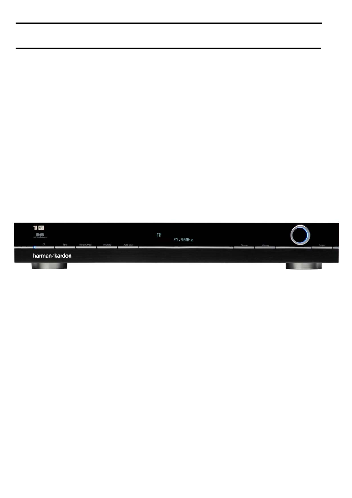
TU 970II/230
FM/AM/DAB Tuner
TECHNICAL SPECIFICATIONS 2
TROUBLESHOOTING GUIDE 3
FRONT PANEL CONTROLS 4
REAR PANEL CONNECTIONS 5
REMOTE CONTROL FUNCTIONS 6
EXPLODED VIEW AND PARTS 7
Released EU2008 harman/kardon, Inc. Rev 0, 10/2008
250 Crossways Park Dr.
Woodbury, New York, 11797
CONTENTS
ELECTRICAL PARTS LIST 8
SEMICONDUCTOR FUNCTION/PINOUTS 15
PCB DRAWINGS 18
BLOCK DIAGRAM 19
WIRING DIAGRAM 20
SCHEMATIC DIAGRAM 21
Page 2

Technical Specifications
harman/kardon
TU 970II/230 Service Manual
Page 2 of 21
FM Section
Frequency Range 87.50 MHz to 108.00 MHz (50 kHz steps)
Signal-to-Noise Ratio 65 dB (Mono) 60 dB (Stereo)
Presets 30
Section
AM
Frequency Rang 522 kHz to 1620 kHz (9 kHz steps)
Signal-to-Noise Ratio 35 dB
Presets 30
DAB Section
RF Section Band lll, 174 MHz - 240 MHz
Band L, 1452 MHz - 1492 MHz
Input: 50 Ohm, nominal
Max signal: -3 dBm typ
Sensitivity: -96 dBm typ
Adjacent Channel Rejection: 35dB typ
Display 2 line by 16 character DOT Matrix
Presets 99
Audio Output Stereo, 2.5V P-P
48 kHz sample rate 16 bit sample resolution
Optical S/PDIF IEC60958 Compliant
48 kHz sample rate 24 bit sample resolution
General
Power Requirement 230-240 V AC, 50 Hz
Power Consumption 12 W
3 W (standby)
Dimension (Max)
Width 442 mm
Height 63 mm
Depth 299 mm
Weight 3.4 kg
Depth measurement includes knobs, buttons and terminal connections. Height measurement includes feet and chassis.
All features and specifications are subject to change without notice.
Harman Kardon and Power for the Digital Revolution are registered trademarks of Harman Kardon, Incorporated
Page 3

Troubleshooting Guide
harman/kardon
TU 970II/230 Service Manual
Page 3 of 21
This unit is designed for trouble-free operation. Most problems users encounter are due to operating errors. If you have a problem, first check this list for a
possible solution. If the problem persists, consult your authorized Harman Kardon Service Center.
If the problem is... Make sure that the...
No lights appear when System Power button is pressed Unit is plugged into a live outlet.
No sound is heard Tune to an active station.
Sound distorts, particularly in stereo mode. Use a more directional antenna.
Intermittent or continuous buzzing or hissing. Place the unit farther away from these appliances. Install noise filters on the appliances.
Display says 'No stations Available' Check that antenna is connected.
Display has gone blank or says 'service off air' This may occur if a broadcaster changes the label of a service or removes a label whilst you
Make sure the outlet is active.
Check for correct amplifier settings.
Check the connections and wires.
Ensure that DAB coverage exists in your area.
are listening to it. Try to retune to this station, using the Autotune procedure.
Page 4
1
3
4
5
6
7
8
2
@
9A
Front Panel Controls
harman/kardon
TU 970II/230 Service Manual
Page 4 of 21
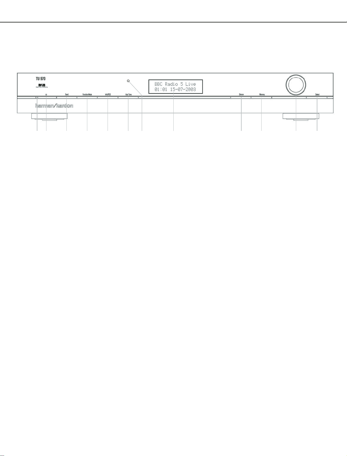
Power Indicator
1
System Power Control
2
Band selector
3
Function/FM Mode Selector
Power Indicator: This LED will illuminate in
amber when the unit is in the Standby mode to
signal that the unit is ready to be turned on.
When the unit is in operation, the indicator will
turn blue.
1
System Power Control: Press this button
to turn on the TU 970 II; press it again to turn
the unit off (to Standby). Note that the Power
Indicator
next to the switch will turn blue
when the unit is on.
2
Band Selector: Press this button to change
between the DAB, FM and AM frequency bands.
3
Function/FM Mode Selector: In DAB
mode, pressing this button will activate station
order, preset tune, Dynamic Rate Control or
manual tune features. In FM mode, press this
button to select the stereo or mono mode for
FM tuning. In the stereo mode, the word
STEREO
Display
will be shown in the Information
6
, and stereo reception will be
provided when stations are transmitting stereo
signals. In the mono mode, the left and right
signals from stereo broadcasts will be mixed
together and reproduced through all channels.
Select
MONO
for better reception of weak
signals.
4
Info/RDS Button
5
Auto Tune Button
6
Information Display
7
Dimmer
4
Info/RDS Button: In DAB mode, pressing
this button will change the content of the lower
display line of the Information Display as shown
on page 9, as well as signal error rate and soft-
ware version. In RDS mode, it will change
between the different RDS options.
5
Auto Tune Button: In DAB mode, press this
button to automatically scan all available
stations.
6
Information Display: This dual line display
delivers messages and status indications to help
you operate the tuner.
7
Dimmer: Press this button to dim the front
panel display.The first press of the button will
dim the displays to one-half normal brightness;
the next press will turn back to normal brightness.The display will return to normal brightness
the next time the unit is turned on.
8
Memory Button: Press this button to open
the memory position that stores a preset
location in the tuner. 99 DAB presets can be
stored, as well as 30 FM and 30 AM presets.
(See page 9 for more information on tuner
presets.)
8
Memory
9
Control Ring
A
Select
B
Remote Control Sensor
9
Control Ring: Turn counterclockwise to
tune lower frequency stations and clockwise to
tune higher frequency stations.When a station
with a strong signal is tuned, the Information
Display
6
will read
TUNED
. Turn again to
tune to the next frequency increment in Manual
Tune Mode, or automatically to the next
station with a signal strong enough for
acceptable reception in Auto Tune Mode.
The ring also controls the parameters in the
different menus.
A Select: In FM or AM mode, press this
button to select Auto Tune, Manual Tune or
Preset Tune. In DAB mode, press this button to
select the displayed station.
B
Remote Sensor Window:The sensor
behind this window receives infrared signals
from the remote control. Aim the remote at this
area and do not block or cover it unless an
external remote sensor is installed.
Page 5
Rear Panel Connections
7
6
3
5
4
2
1
0
harman/kardon
TU 970II/230 Service Manual
Page 5 of 21
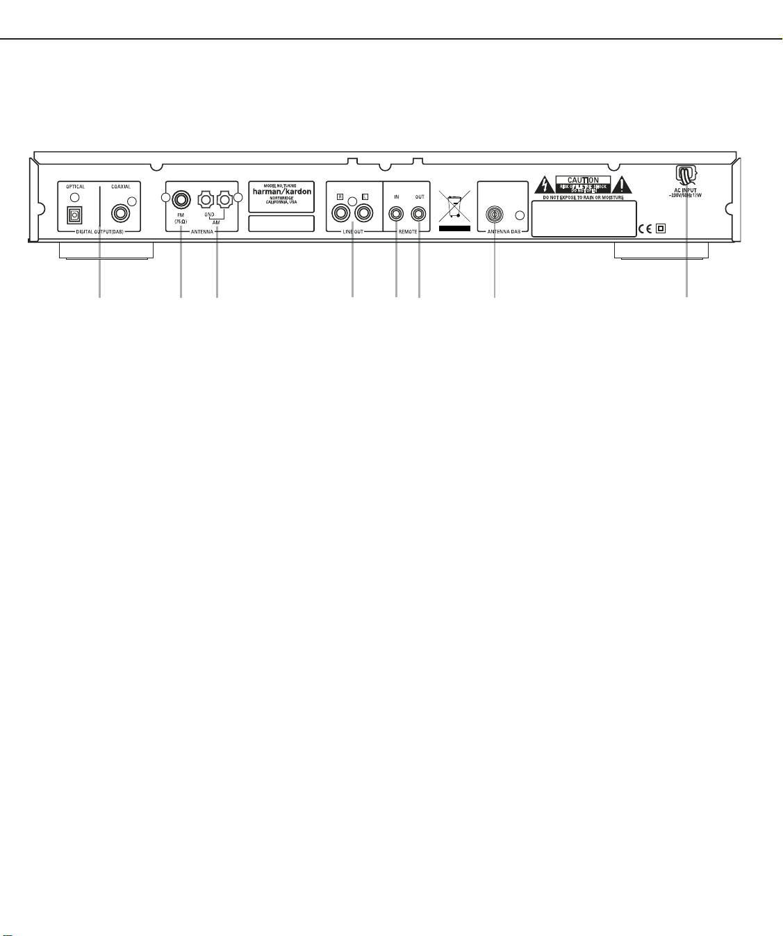
Optical and Coaxial Digital Outputs
FM Antenna
AM Antenna
Analog Audio Outputs
DAB Antenna
Optical and Coaxial Digital Outputs:
Connect one of these jacks to the optical or
coaxial digital input of your pre amplifier or
integrated amplifier, if available.
Note that these digital outputs only contain the
digital signal from the DAB stations. For FM/AM
reception, you will have to connect the analog
outputs at all times.
FM Antenna: Connect an indoor or exter-
nal FM antenna to this terminal.
AM Antenna: Connect the AM loop
antenna supplied with the receiver to these
terminals. If an external AM antenna is used,
make connections to the AM and GND
terminals in accordance with the instructions
supplied with the antenna.
AC Power Cord
Remote Control Output
Remote Control Input
Analog Audio Outputs: Connect these
jacks to the tuner input of your pre amplifier or
integrated amplifier for analog audio playback.
Be certain to observe proper channel
connections using the color-coded cables and
connectors so that red connects right channels
and white connects left channels.
NOTE: Before making any audio connections,
unplug all components of your audio system
from their AC power outlets. To reduce the
possibility of hum or noise in your system, place
all audio interconnection cables away from both
AC power cords and speaker wires.
DAB Antenna: Connect a DAB antenna to
this terminal.
AC Power Cord: Connect this plug to an
AC outlet. If the outlet is controlled by a switch,
make certain that it is in the ON position.
Remote Control Output: Connect this
jack to the infrared (IR) input jack of another
compatible Harman Kardon remote controlled
product to have the built-in Remote Sensor on
the tuner provide IR signals to other compatible
products.
Remote Control Input: Connect the
output of a remote infrared sensor, or the
remote control output of another compatible
Harman Kardon product, to this jack. This will
enable the remote control to operate even when
the front panel Remote Sensor on the tuner is
blocked. This jack may also be used with
compatible IR remote control-based automation
systems.
Page 6
Remote Control Functions
harman/kardon
TU 970II/230 Service Manual
Page 6 of 21
0
1
2
3
4
5
8
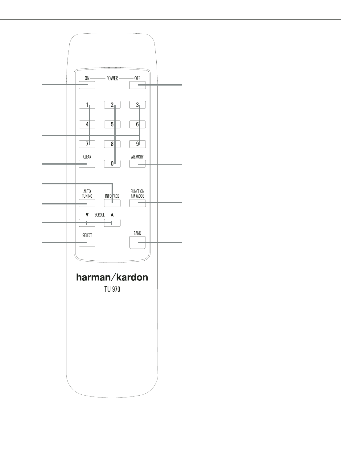
0
Standby/Power On
1
Numeric Keys
2
Clear Button
3
Info/RDS Button
4
Auto Tuning Button
5
Scroll Button
6
Function/FM Mode Selector
7
Band Selector
8
Select Button
9
Memory Button
A
Standby/Power Off
A
9
6
7
0
Standby/Power On: Press this button to
turn on the TU 970 II. Note that the Power
Indicator
when the unit is on.
1
ten-button numeric keypad to enter tuner preset
positions or to tune stations directly.
2
presets from your station list.
3
change the content of the lower display line of
the Information Display as well as signal error
rate and software version. (See page 9 for more
info).
4
this button to automatically scan all available
stations.
5
frequency stations and
frequency stations.When a station with a strong
signal is tuned, the Information Display
will read
the next frequency increment in Manual Tune
Mode, or keep pressed for automatic search for
the next station with a signal strong enough for
acceptable reception in Auto Tune Mode.These
buttons also control the parameters in the
different menus, like the Control Ring
the front panel.
6
mode, pressing this button will activate station
order, preset tune, Dynamic Rate Control or
manual tune features. In FM mode, press this
button to select the stereo or mono mode for FM
tuning. In the stereo mode, the word
will be shown in the Information Display6,
and stereo reception will be provided when
stations are transmitting stereo signals. In the
mono mode, the left and right signals from stereo
broadcasts will be mixed together and
reproduced through all channels. Select
for better reception of weak signals.
7
between the DAB, FM and AM frequency bands.
8
button to select Auto Tune, Manual Tune or Preset
Tune.
9
the memory position that stores a preset location
in the tuner. 99 DAB presets can be stored, as
well as 30 FM and 30 AM presets. (See page 9
for more information on tuner presets.)
A
turn the unit off (to Standby).
next to the switch will turn blue
Numeric Keys: These buttons serve as a
Clear Button: Press this button to clear
Info/RDS Button: Pressing this button will
Auto Tune Button: In DAB mode, press
Scroll Buttons: Press L to tune lower
K to tune higher
6
TUNED
. Press again briefly to tune to
9
on
Function/FM Mode Selector: In DAB
STEREO
MONO
Band Selector: Press this button to change
Select: In FM or AM mode, press this
Memory Button: Press this button to open
Standby/Power Off: Press this button to
Page 7
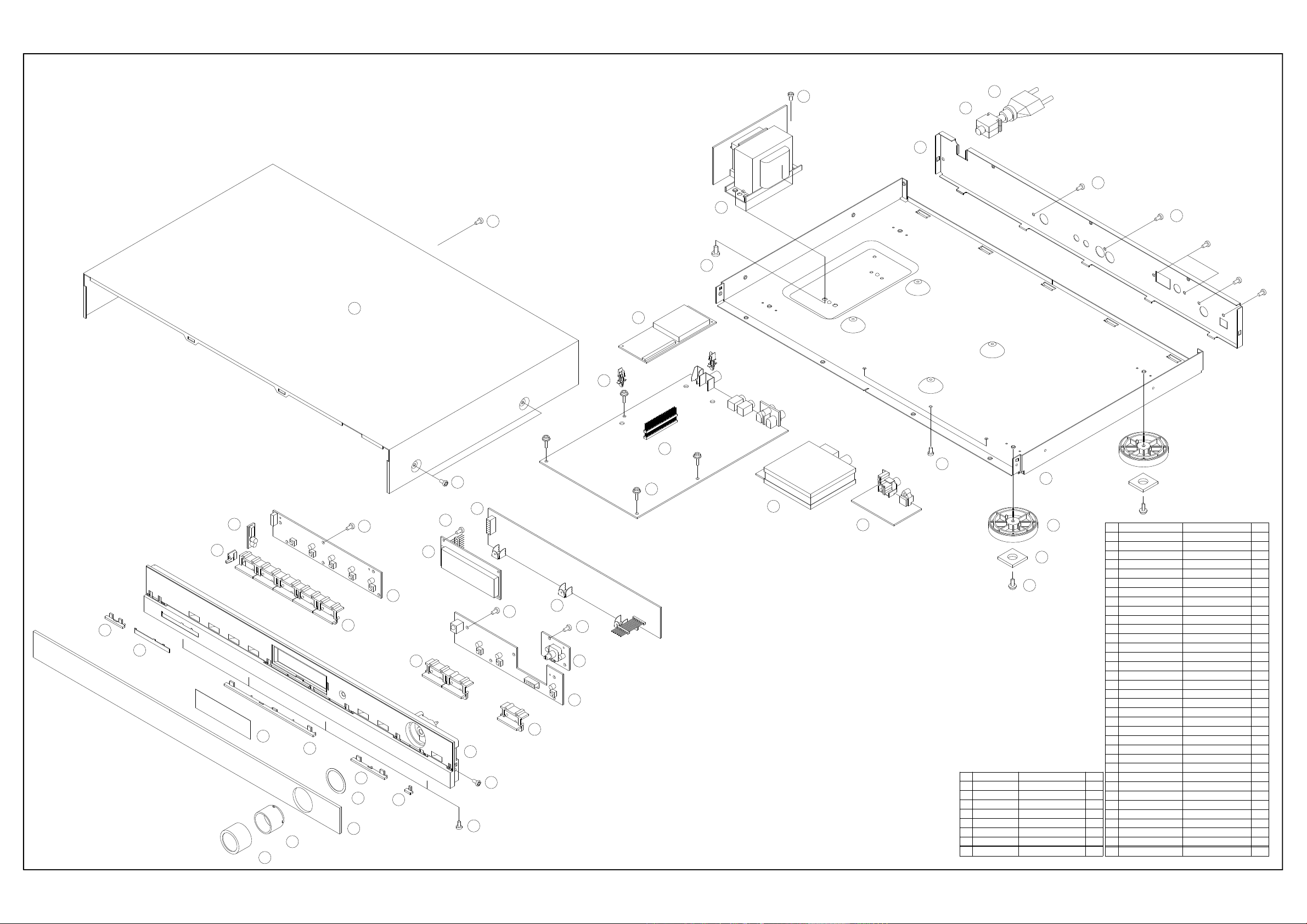
EXPLODED VIEW (TU 970II)
harman/kardon
TU 970II/230 Service Manual
Page 7 of 21
S2
35
34
33
S5
S6
32
X5
S7
X4
S4
X5
23
25
24
26
S2
X3
S6
12
16
S1
X4
21
S1
X6
X4
20
S3
X4
27
28
17
S1
X5
4
13
22
S1
X2
5
14
19
18
9
6
7
10
8
3
11
S8
S2
X4
2
1
15
CTS3+8JFC
X2
S8
S7
S6
S5
S4
S3
S2
S1
NO.
CHD1A023
CTB3+8JFC
CTB3+6JFZ
CTB3+10GFZ
CTW3+8J
CTB3+6J
CTB3+10G
PARTS NO.
29
30
31
X4
S3
X4
SCREW
SCREW, TRANS
SCREW
SCREW
SCREW
SCREW
SCREW
SCREW
DESCRIPTION
Q'TY
1
132
4
4
1
1
1
1
1
2
1
3
1
1
1
1
1
1
1
1
1
1
1
1
1
1
1
1
1
1
1
1
35
X4
Q'TY
CJA2B043ZA
KHR1A028
34
CKF1A275Z
33
31
KHG1A050
30
CKL1A186H43
29
CUA1A240
28
27
CNVMB114MA18L
26
COP11666B
25
24
CMH1A226
23
CKC1B151S46
22
CMD1A501
21
20
HFL16T202DA1E
19
18
17
16
KBT1A920MBC22
15 KNOB, SELECT
KBT1A919MBC22
14
13 KBT1A918MBC22
CGL1A227
12
11
CGW1A374RDH43
10
CMZ1A095
9
CMZ1A093 FILTER, FIP 1
8
KGR1A328MBC22
4
7
KGR1A327MBC22
4
6
KGR1A326MBC22
9
5
1
KGB1A111X
5
4
KGR1A325MBC22
3
CGU1A324Z
8
2
CGL1A229
6
1
KGX1A344MBC22
17
NO.
PARTS NO.
POWER CORD
BUSHING, AC CORD 1
PANEL, REAR 1
PCB(TRANS)
CUSHION, FOOT
FOOT
CHASSIS, BOTTOM
PCB(JACK)
TUNER MODULE
PCB(MAIN)
DAB MODULEHNVFS2020VENICE
SUPPORT, PCB
CABINET, TOP
BRACKET, FIP
PCB(MICOM)
FIP MODULE
PCB(ROTARY)
PCB(FRONT)
PCB(FRONT)
PCB(LED)
KNOB, MEMORY
KNOB, POWER
INDICATOR, POWER
PANEL, FRONT
SHEET, ROTARY
ORNAMENT, BAR(D)
ORNAMENT, BAR(C)
ORNAMENT, BAR(B)
BADGE
ORNAMENT, BAR(A)
WINDOW, FIP
INDICATOR, ROTARY
CAP, ROTARY
DESCRIPTION
Page 8

TU 970II/230 FM/AM/DAB TUNER
harman/kardon
TU 970II/230 Service Manual
Page 8 of 21
POS PART NUMBER PART NAME COMMENTS
CHE154 CLAMPER , ARM
CQXTU970II/230 INSTRUCTION MANUAL ASS'Y
CARTTU970II REMOCON , TRANSMITER ASS'Y
CJS4M009X CORD, PIN CORD, PIN
CJS4N014Z CORD , PIN
CJS9D002Z CORD , JACK(MONO) 1200MM
CQX1A1145Z MANUAL, INSTRUCTION
CGL1A229 INDICATOR, ROTARY
CGWTU970II/230 FRONT PANEL ASS'Y
CBT1A918MBG27 KNOB, POWER
CBT1A919MBG27 KNOB, MEMORY
CBT1A920MBG27 KNOB, SELECT
CGL1A227 INDICATOR, POWER
CGU1A324X WINDOW, FIP
CGU1A324X-1 WINDOW, FIP
CGW1A374RDH43 PANEL, FRONT TU970
CMZ1A093 FILTER, FIP PVC 0.4T
CMZ1A095 SHEET, ROTARY
CTB3+10GR SCREW
CTW3+10GR SCREW
CWC1C4A23B160B CABLE , CARD
HFL16T202DA1E VFD , MODULE 16T202DA1E
FIP1 KJP14TT152ZY PIN HEADER (2.54MM)
CGX1A344MBG27 CAP, ROTARY
CHG1A113 RUBBER
CHR301 CLAMPER
BKC1C151S46 SHEET , CABINET(296X560) ALKOR 40211
CUATU970II/230 BOTTOM CHASSIS ASS'Y
CHD1A023R SCREW , SPECIAL
CMH1A226 SUPPORT , PCB
CNE1A009 NUT, DAB M3/8X32
CNVFS2022V131C MODULE , DUAL DAB FS2022-0101-0005
CNVMB114MA18L TUNER MODULE(EUR)
CNW1A038 WASHER 9.5X15
COP11923B PCB , ASS'Y
CIP11923B PCB , AUTO ASS'Y
CUP11923Z PCB , MAIN
C101 CCEA1CH471T CAP , ELECT 470UF 16V
C104 CCFT1H223ZF CAP, CERAMIC 22000UF 50V
C201 CCEA1AH471T CAP , ELECT 470UF 10V
C202 CCFT1H223ZF CAP, CERAMIC 22000UF 50V
C203 CCEA1AH471T CAP , ELECT 470UF 10V
C204 CCFT1H223ZF CAP, CERAMIC 22000UF 50V
C205 CCEA1HH4R7T CAP , ELECT 4.7UF 50V
C206 CCCT1H220JC CAP , CERAMIC 22UF 50V
C207 CCFT1H223ZF CAP, CERAMIC 22000UF 50V
C208 CCEA1AH101T CAP , ELECT 100UF 10V
C209 CCEA1HH4R7T CAP , ELECT 4.7UF 50V
C210 CCFT1H223ZF CAP, CERAMIC 22000UF 50V
C211 CCEA1AH101T CAP , ELECT 100UF 10V
C212 CCEA1HH4R7T CAP , ELECT 4.7UF 50V
C213 CCCT1H220JC CAP , CERAMIC 22UF 50V
Page 9

POS PART NUMBER PART NAME COMMENTS
harman/kardon
TU 970II/230 Service Manual
Page 9 of 21
C214 CCFT1H223ZF CAP, CERAMIC 22000UF 50V
C215 CCEA1AH101T CAP , ELECT 100UF 10V
C216 CCEA1HH4R7T CAP , ELECT 4.7UF 50V
C217 CCEA1AH101T CAP , ELECT 100UF 10V
C218 CCFT1H223ZF CAP, CERAMIC 22000UF 50V
C219 CCEA1HH4R7T CAP , ELECT 4.7UF 50V
C220 CCEA1HH4R7T CAP , ELECT 4.7UF 50V
C221 HCQI1H152JZT CAP , MYLAR 1500UF 50V
C222 HCQI1H152JZT CAP , MYLAR 1500UF 50V
C223 CCEA1HH4R7T CAP , ELECT 4.7UF 50V
C224 CCEA1HH4R7T CAP , ELECT 4.7UF 50V
C225 CCFT1H103ZF CAP, CERAMIC 10000UF 50V
C226 CCKT1H102KB CAP , CERAMIC 1000UF 50V
C228 CCEA1HH4R7T CAP , ELECT 4.7UF 50V
C229 CCEA1AH101T CAP , ELECT 100UF 10V
C230 CCEA1CH470T CAP , ELECT 47UF 16V
C231 CCFT1H104ZF CAP , SEMICONDUCTOR 100nF 50V
C234 CCCT1H330JC CAP , CERAMIC 33UF 50V
C235 CCEA1AH101T CAP , ELECT 100UF 10V
C701 CCEA1AH471T CAP , ELECT 470UF 10V
C702 CCCT1H330JC CAP , CERAMIC 33UF 50V
C703 CCCT1H330JC CAP , CERAMIC 33UF 50V
C704 CCFT1H223ZF CAP, CERAMIC 22000UF 50V
C705 CCKT1H221KB CAP , CERAMIC 220UF 50V
C706 CCKT1H221KB CAP , CERAMIC 220UF 50V
C707 CCEA1AH101T CAP , ELECT 100UF 10V
C708 CCFT1H223ZF CAP, CERAMIC 22000UF 50V
C709 CCKT1H221KB CAP , CERAMIC 220UF 50V
C710 CCKT1H221KB CAP , CERAMIC 220UF 50V
C711 CCKT1H221KB CAP , CERAMIC 220UF 50V
C714 CCEA1AH101T CAP , ELECT 100UF 10V
C715 CCFT1H223ZF CAP, CERAMIC 22000UF 50V
C716 CCEA1AH471T CAP , ELECT 470UF 10V
C717 CCFT1H223ZF CAP, CERAMIC 22000UF 50V
C718 CCKT1H101KB CAP , CERAMIC 100UF 50V
C719 CCKT1H101KB CAP , CERAMIC 100UF 50V
C720 CCKT1H101KB CAP , CERAMIC 100UF 50V
C721 CCKT1H101KB CAP , CERAMIC 100UF 50V
C722 CCKT1H101KB CAP , CERAMIC 100UF 50V
C723 CCKT1H101KB CAP , CERAMIC 100UF 50V
C724 CCFT1H223ZF CAP, CERAMIC 22000UF 50V
C726 CCEA1CH470T CAP , ELECT 47UF 16V
C727 CCFT1H223ZF CAP, CERAMIC 22000UF 50V
C901 CCFT1H223ZF CAP, CERAMIC 22000UF 50V
C902 CCFT1H223ZF CAP, CERAMIC 22000UF 50V
C903 CCFT1H223ZF CAP, CERAMIC 22000UF 50V
C904 CCFT1H223ZF CAP, CERAMIC 22000UF 50V
C905 CCEA1HH220T CAP , ELECT 22UF 50V
C906 CCFT1H223ZF CAP, CERAMIC 22000UF 50V
C908 CCEA1AH101T CAP , ELECT 100UF 10V
C909 CCFT1H223ZF CAP, CERAMIC 22000UF 50V
C910 CCEA1CH101T CAP , ELECT 100UF 16V
C911 CCFT1H223ZF CAP, CERAMIC 22000UF 50V
Page 10

POS PART NUMBER PART NAME COMMENTS
harman/kardon
TU 970II/230 Service Manual
Page 10 of 21
C914 CCEA1AH101T CAP , ELECT 100UF 10V
C915 CCFT1H223ZF CAP, CERAMIC 22000UF 50V
C916 CCEA1AH101T CAP , ELECT 100UF 10V
C917 CCFT1H223ZF CAP, CERAMIC 22000UF 50V
C918 CCEA1AH101T CAP , ELECT 100UF 10V
C919 CCFT1H223ZF CAP, CERAMIC 22000UF 50V
C920 CCEA1AH101T CAP , ELECT 100UF 10V
C921 CCFT1H223ZF CAP, CERAMIC 22000UF 50V
C922 CCEA1AH101T CAP , ELECT 100UF 10V
C923 CCFT1H223ZF CAP, CERAMIC 22000UF 50V
C924 CCEA1CH471T CAP , ELECT 470UF 16V
C925 CCFT1H223ZF CAP, CERAMIC 22000UF 50V
C926 CCEA1AH101T CAP , ELECT 100UF 10V
C927 CCFT1H223ZF CAP, CERAMIC 22000UF 50V
C928 CCEA1AH470T CAP , ELECT 47UF 10V
C929 CCFT1H223ZF CAP, CERAMIC 22000UF 50V
D201 CVDZJ3.3BT DIODE , ZENER ZJ3.3B 1/2W
D202 CVD1SS133MT DIODE 1SS133
D702 CVD1SS133MT DIODE 1SS133
D703 CVD1SS133MT DIODE 1SS133
D706 CVD1SS133MT DIODE 1SS133
D707 CVD1SS133MT DIODE 1SS133
D708 CVD1SS133MT DIODE 1SS133
D719 CVD1SS133MT DIODE 1SS133
D720 CVD1SS133MT DIODE 1SS133
D901 CVD1N4003ST RECT , DIODE 1N4003
D902 CVD1N4003ST RECT , DIODE 1N4003
D903 CVD1N4003ST RECT , DIODE 1N4003
D904 CVD1N4003ST RECT , DIODE 1N4003
D905 CVD1N4003ST RECT , DIODE 1N4003
D906 CVD1SS133MT DIODE 1SS133
D907 CVDZJ4.7BT DIODE , ZENER ZJ4.7B 1/2W
D908 CVD1N4003ST RECT , DIODE 1N4003
D909 CVD1N4003ST RECT , DIODE 1N4003
D910 CVDZJ6.2BT DIODE , ZENER ZJ6.2B 1/2W
D911 CVDZJ6.2BT DIODE , ZENER ZJ6.2B 1/2W
D912 CVD1N4003ST RECT , DIODE 1N4003
D913 CVD1SS133MT DIODE 1SS133
F901 KJCFC5S HOLDER , FUSE
IC72 HVIRE5VL28CATZ IC , RESET
Q201 HVTKTC2874BT T.R , MUTE KTC2874B
Q202 HVTKTC2874BT T.R , MUTE KTC2874B
Q203 HVTKRA107MT T.R KRA107M
Q204 HVTKRC107MT T.R KRC107M
Q205 HVTKRA107MT T.R KRA107M
Q701 HVTKRA107MT T.R KRA107M
Q702 HVTKRA107MT T.R KRA107M
Q703 HVTKRA107MT T.R KRA107M
Q704 HVTKRA107MT T.R KRA107M
Q705 HVTKRA107MT T.R KRA107M
Q709 HVTKRC102MT T.R KRC102M
Q710 HVTKRC107MT T.R KRC107M
Q711 HVTKRC102MT T.R KRC102M
Page 11

POS PART NUMBER PART NAME COMMENTS
harman/kardon
TU 970II/230 Service Manual
Page 11 of 21
Q712 HVTKSA1175YT T.R KSA1175Y(DEAD)
Q713 HVTKSC2785YT T.R KSC2785Y
Q905 HVTKTC3198YT T.R KTC3198Y
Q906 HVTKTA1266YT T.R TKTA1266YT
R101 CRD25TJ4R7T RES , CARBON
R104 CRD20TJ102T RES , CARBON 1K OHM 1/5W J
R105 CRD20TJ102T RES , CARBON 1K OHM 1/5W J
R201 CRD20TJ102T RES , CARBON 1K OHM 1/5W J
R203 CRD20TJ473T RES , CARBON 47K OHM 1/5W J
R205 CRD20TJ223T RES , CARBON 22K OHM 1/5W J
R206 CRD20TJ151T RES , CARBON 150 OHM 1/5W J
R207 CRD20TJ151T RES , CARBON 150 OHM 1/5W J
R208 CRD20TJ473T RES , CARBON 47K OHM 1/5W J
R209 CRD20TJ473T RES , CARBON 47K OHM 1/5W J
R210 CRD20TJ223T RES , CARBON 22K OHM 1/5W J
R212 CRD20TJ151T RES , CARBON 150 OHM 1/5W J
R213 CRD20TJ473T RES , CARBON 47K OHM 1/5W J
R214 CRD20TJ103T RES , CARBON 10K OHM 1/5W J
R215 CRD20TJ104T RES , CARBON 100K OHM 1/5W J
R216 CRD20TJ104T RES , CARBON 100K OHM 1/5W J
R217 CRD20TJ103T RES , CARBON 10K OHM 1/5W J
R218 CRD20TJ151T RES , CARBON 150 OHM 1/5W J
R219 CRD20TJ102T RES , CARBON 1K OHM 1/5W J
R220 CRD20TJ102T RES , CARBON 1K OHM 1/5W J
R221 CRD20TJ104T RES , CARBON 100K OHM 1/5W J
R222 CRD20TJ104T RES , CARBON 100K OHM 1/5W J
R223 CRD20TJ102T RES , CARBON 1K OHM 1/5W J
R224 CRD20TJ102T RES , CARBON 1K OHM 1/5W J
R225 CRD20TJ102T RES , CARBON 1K OHM 1/5W J
R226 CRD20TJ104T RES , CARBON 100K OHM 1/5W J
R227 CRD20TJ104T RES , CARBON 100K OHM 1/5W J
R228 CRD20TJ104T RES , CARBON 100K OHM 1/5W J
R229 CRD20TJ102T RES , CARBON 1K OHM 1/5W J
R230 CRD20TJ102T RES , CARBON 1K OHM 1/5W J
R231 CRD20TJ221T RES , CARBON 220 OHM 1/5W J
R232 CRD20TJ152T RES , CARBON 1.5K OHM 1/5W J
R233 CRD20TJ152T RES , CARBON 1.5K OHM 1/5W J
R234 CRD20TJ102T RES , CARBON 1K OHM 1/5W J
R235 CRD20TJ104T RES , CARBON 100K OHM 1/5W J
R236 CRD20TJ472T RES , CARBON 4.7K OHM 1/5W J
R237 CRD20TJ104T RES , CARBON 100K OHM 1/5W J
R238 CRD20TJ472T RES , CARBON 4.7K OHM 1/5W J
R239 CRD20TJ101T RES , CARBON 100 OHM 1/5W J
R240 CRD20TJ750T RES , CARBON 75 OHM 1/5W J
R241 CRD20TJ750T RES , CARBON 75 OHM 1/5W J
R243 CRD20TJ100T RES , CARBON 10 OHM 1/5W J
R245 CRD20TJ271T RES , CARBON 270 OHM 1/5W J
R246 CRD20TJ470T RES , CARBON 47 OHM 1/5W J
R247 CRD20TJ102T RES , CARBON 1K OHM 1/5W J
R248 CRD20TJ332T RES , CARBON 3.3K OHM 1/5W J
R249 CRD20TJ101T RES , CARBON 100 OHM 1/5W J
R250 CRD20TJ102T RES , CARBON 1K OHM 1/5W J
R704 CRD20TJ470T RES , CARBON 47 OHM 1/5W J
Page 12

POS PART NUMBER PART NAME COMMENTS
harman/kardon
TU 970II/230 Service Manual
Page 12 of 21
R705 CRD20TJ332T RES , CARBON 3.3K OHM 1/5W J
R706 CRD20TJ102T RES , CARBON 1K OHM 1/5W J
R707 CRD20TJ470T RES , CARBON 47 OHM 1/5W J
R711 CRD20TJ103T RES , CARBON 10K OHM 1/5W J
R712 CRD20TJ103T RES , CARBON 10K OHM 1/5W J
R713 CRD20TJ103T RES , CARBON 10K OHM 1/5W J
R718 CRD20TJ102T RES , CARBON 1K OHM 1/5W J
R719 CRD20TJ102T RES , CARBON 1K OHM 1/5W J
R720 CRD20TJ102T RES , CARBON 1K OHM 1/5W J
R721 CRD20TJ102T RES , CARBON 1K OHM 1/5W J
R722 CRD20TJ152T RES , CARBON 1.5K OHM 1/5W J
R723 CRD20TJ182T RES , CARBON 1.8K OHM 1/5W J
R724 CRD20TJ272T RES , CARBON 2.7K OHM 1/5W J
R725 CRD20TJ332T RES , CARBON 3.3K OHM 1/5W J
R726 CRD20TJ562T RES , CARBON 5.6K OHM 1/5W J
R727 CRD20TJ752T RES , CARBON 7.5K OHM 1/5W J
R728 CRD20TJ102T RES , CARBON 1K OHM 1/5W J
R729 CRD20TJ102T RES , CARBON 1K OHM 1/5W J
R730 CRD20TJ102T RES , CARBON 1K OHM 1/5W J
R731 CRD20TJ102T RES , CARBON 1K OHM 1/5W J
R732 CRD20TJ102T RES , CARBON 1K OHM 1/5W J
R733 CRD20TJ105T RES , CARBON 1M OHM 1/5W J
R734 CRD20TJ181T RES , CARBON 180 OHM 1/5W J
R735 CRD20TJ471T RES , CARBON 470 OHM 1/5W J
R736 CRD20TJ221T RES , CARBON 220 OHM 1/5W J
R739 CRD20TJ561T RES , CARBON 560 OHM 1/5W J
R740 CRD20TJ103T RES , CARBON 10K OHM 1/5W J
R741 CRD20TJ103T RES , CARBON 10K OHM 1/5W J
R742 CRD20TJ102T RES , CARBON 1K OHM 1/5W J
R743 CRD20TJ102T RES , CARBON 1K OHM 1/5W J
R744 CRD20TJ102T RES , CARBON 1K OHM 1/5W J
R901 CRD20TJ472T RES , CARBON 4.7K OHM 1/5W J
R902 CRD20TJ102T RES , CARBON 1K OHM 1/5W J
R903 CRD20TJ103T RES , CARBON 10K OHM 1/5W J
R904 CRD20TJ104T RES , CARBON 100K OHM 1/5W J
R905 CRD20TJ104T RES , CARBON 100K OHM 1/5W J
R906 CRD20TJ102T RES , CARBON 1K OHM 1/5W J
R907 CRD20TJ102T RES , CARBON 1K OHM 1/5W J
R912 CRD20TJ102T RES , CARBON 1K OHM 1/5W J
S701 HST1A020ZT SW , TACT
S702 HST1A020ZT SW , TACT
S703 HST1A020ZT SW , TACT
S704 HST1A020ZT SW , TACT
S705 HST1A020ZT SW , TACT
S706 HST1A020ZT SW , TACT
S707 HST1A020ZT SW , TACT
S709 HST1A020ZT SW , TACT
BAT1 CAB30H3A3H BATTERY , RECHARGEABLE 30H3A3H
BN21 CJP44TT153ZY PIN , HEADER (2.00MM) DAB2025
BN23 CWZTU970BN23 WIRE , SILED ASS'Y
BN71 KJP14HA151ZY PIN SOCKET (2.54MM)
BN74 KJP06TT154ZY PIN HEADER (2.54MM)
BN75 CWB2B903090EN WIRE ASS'Y ADVD-6500
Page 13

POS PART NUMBER PART NAME COMMENTS
harman/kardon
TU 970II/230 Service Manual
Page 13 of 21
BN76 CWB2B904110EN WIRE ASS'Y
BN77 CWB1C902050EN WIRE ASS'Y
BN78 CWB2B907140EN WIRE ASS'Y
BN79 CJP05GB99ZY WAFER ANGLE
BN92 CWB1E907150BM WIRE ASS'Y
CN23 CJP03GB46ZY WAFER , ANGLE , 3PIN
CN72 CJP23GA115ZY WAFER , CARD CABLE
CN73 CJP06GB46ZY WAFER , ANGLE , 6PIN
CN74 CJP06HA37ZM WAFER
CN75 CJP03GA19ZM WAFER
CN76 CJP04GA19ZM WAFER
CN77 CJP02GA19ZM WAFER
CN78 CJP07GB46ZY WAFER, ANGLE, 7PIN
CN79 CJP05GA98ZM WAFER
CN91 CJP02KA060ZY WAFER
CN92 CJP07GA01ZY WAFER, STRAIGHT, 7PIN
C900 HCQE2E104KDE CAP , LINE ACROSS
C907 CCEA1CH103E CAP , ELECT
C912 CCEA1EH222E CAP , ELECT 2200UF 25V
C913 CCEA1CH102E CAP , ELECT
C930 CCEA1CH682E CAP , ELECT
D701 CVD52CSBBCEAB2 BLUE L.E.D
D709 CVD52CSBBCEAB2 BLUE L.E.D
D711 CVD50BOGDWGA L.E.D , 2 COLOR
D718 CVD52CSBBCEAB2 BLUE L.E.D
ET21 CMD1A387 BRACKET , PCB
ET71 CMD1A501 BRACKET , FIP
ET72 CMD1A501 BRACKET , FIP
ET73 CMD1A501 BRACKET , FIP
ET91 CNE75 PLATE , EARTH
ET92 CNE75 PLATE , EARTH
IC21 HVINJM2068MDTE1 I.C , OP AMP NJM2068MD-TE1
IC22 HVI74HC4066D I.C , SWITCHING(QUAD) 74HC4066D
IC23 HVI74HCU04AFNG I.C , INVERTER TC74HCU04AFNG(TOSHIB
IC24 BVIKP1010B IC, PHOTO COUPLER
IC71 HVIS3F84BB I.C , FLASH U-COM S3F84BB
IC91 HVIKA78R05ZA I.C ASS'Y
CMY2A048 HEAT SINK
CTB3+8JR SCREW
HVIKA78R05 REGULATOR (5V OUTPUT LOW DROP) KA78R05TU
IC92 HVIKA78R05ZA I.C ASS'Y
CMY2A048 HEAT SINK
CTB3+8JR SCREW
HVIKA78R05 REGULATOR (5V OUTPUT LOW DROP) KA78R05TU
IC93 HVIKA78R12ZA I.C , ASS'Y
CMY2A048 HEAT SINK
CTB3+8JR SCREW
HVIKA78R12 REGULATOR(12V OUTPUT LOW DROP) KA78R12TU
IC94 HVILM1117S-3V3 I.C , REGULATOR (3.3V) 1117S-3.3V
JK21 CJJ4N063Z JACK , BOARD
JK22 HJSTOTX177L MODULE , OPTICAL(TX) TOTX177L
JK24 CJJ4M041Y JACK , BOARD (COAX)
JK25 CJJ2D008Z JACK , STEREO
Page 14

POS PART NUMBER PART NAME COMMENTS
harman/kardon
TU 970II/230 Service Manual
Page 14 of 21
JK26 CJJ2D008Z JACK , STEREO
JW71 CWE8202070RV WIRE ASS'Y
JW73 CWE8202070RV WIRE ASS'Y
RS71 HRVKSM603TH2 SENSOR IR KSM-603TH2
S708 KST1A010Z SW , TACT CN
T901 CLT5M026YE TRANS , POWER
VE71 HSR2A028Z VR , ENCODER EC12B24S0034ZZZ
WF11 CJP17GA115ZY WAFER , CARDCABLE
WF72 CJP23GA115ZY WAFER , CARD CABLE
X701 HOX10000E220C CRYSTAL
CQB1A644Z LABEL , ORIGIN
CWC1C4A17B070B CABLE , CARD
KHG1A050 RUBBER , CUSHION
F901 KBA2C1000TLEZ FUSE
Page 15

IC71 FUNCTION (MI-COM S3F84BB)
harman/kardon
TU 970II/230 Service Manual
Page 15 of 21
Pin No. PIN NAME I/O DESCRIPTION
1~8 FIP-DA O FIP Data output port
9 N.C - Non connection
10 SINO I UART Data input port
11 SOTO O UART Data output port
12 VDD1 I Power supply port(+5V)
13 VSS1 I GND
14 XTOUT O
15 XIN I
16 TEST I Back-up Input
17,18 N.C - Non connection
19 RESET I Reset input port("L")
20 N.C - Non connection
21 DAB_DIN I DAB Data input port
22 DAB_DOUT O DAB Data output port
23 DAB_CLK O DAB Clock control port("L")
24 FM/AM_MUTE O FM/AM MUTE control port("L")
25 PLL_DATA O PLL Data output port
26 PLL_CE O PLL Enable control port
27 PLL_CLK O PLL Clock control port
28 STEREO I Tuner module stereo control port
29 TUNED I Tuner module tuned control port
30 PLL_DIN I PLL Data input port
31 RDS_CLK O RDS Clock control port
32 RDS_DATA I RDS Data input port
33 BACK_UP I BACK-UP mode control port("L")
34 REMOTE_IN I Remote unit data input port
35~38 N.C - Non connection
39,40 GND I GND
41 SCROLL_UP I Scroll up control port
42 SCROLL_DN I Scroll down control port
43 VREF I A/D converter reference voltage
44 AVSS I
45 GND I
46 KEY3 I
47 KEY2 I
48 KEY1 I KEY 1 control port
49~51 N.C - Non connection
52 VSS2 I GND
53 VDD2 I Power supply port(+5V)
54 SYSTEM_MUTE O System MUTE control port("L")
55 STAND_BY O Standby on control port("L")
56 FM/AM_ON O FM/AM on control port("L")
57 N.C - Non connection
58 POWER_ON O Unit turn on control port("L")
59~64 N.C - Non connection
65~68 OPTION I GND or OPEN
69~70 N.C - Non connection
71 OPTION I GND or OPEN
72~74 N.C - Non connection
75 OPTION I GND or OPEN
76~77 N.C - Non connection
78 RS_P O Register selection port
79 WRITE O Write enable port
80 READ O Read enable port
10MHz crystal connection port
GND
Page 16

S3C84BB/F84BB PRODUCT OVERVIEW
harman/kardon
TU 970II/230 Service Manual
Page 16 of 21
BLOCK DIAGRAM
XIN
XOUT
RESETB
P2.7/TAOUT
P2.6/TACAP
P2.5/TACK
P2.4/TBOUT
P3.7/TCOUT0
P3.6/TCOUT1
P3.4/T1OUT0
P3.2/T1CAP0
P3.0/T1CK0
P3.5/T1OUT1
P3.3/T1CAP1
P3.1/T1CK1
P2.2/SCK
P2.1/SI
P2.0/SO
P5.3/RXD0
P5.2/TXD0
P5.1/RXD1
P5.0/TXD1
P0.0~P0.7/
PG0~PG7
OSC/RESETB
8-Bit
Basic Timer
8-Bit
Timer
/CounterA,B
8-Bit
Timer/
CounterC0,C1
16-Bit
Timer
/Counter10,11
SIO/
UART0,1
PG
AV
REF AVSS
Port 0 Port 1A/D
I/O Port and Interrupt Control
SAM88RC CPU
64K-Byte
ROM
P1.0-P1.7P0.0-P0.7
2064-Byte
RAM
Port 2 P2.0-P2.7
Port 3 P3.0-P3.7
Port 4
Port 5 P5.0-P5.7
Port 6 P6.0-P6.7
P4.0-P4.7/
INT0~INT7
Port 8 Port 7D/A
P8.0-P8.5/
INT8,INT9
P2.3/
DAOUT
P7.0-P7.7/
ADC0~ADC7
Figure 1-1. S3C84BB/F84BB Block Diagram
Page 17

PRODUCT OVERVIEW S3C84BB/F84BB
harman/kardon
TU 970II/230 Service Manual
Page 17 of 21
PIN ASSIGNMENT
P0.7/PG7
P0.6/PG6
P0.5/PG5
P0.4/PG4
P0.3/PG3
P0.2/PG2
P0.1/PG1
P0.0/PG0
P1.7
P1.6
P1.5
P1.4
P1.3
P1.2
P1.1
P1.0
65
66
67
68
69
70
71
72
73
74
75
76
77
78
79
80
P2.7/TAOUT
P2.6/TACAP
P2.5/TACK
P2.4/TBPWM
P2.3/DAOUT
P2.2/SCK
P2.1/SI
P2.0/SO
P5.7
P5.6/SDAT
P5.5/SCLK
VDD1
VSS1
XOUT
XIN
TEST
P5.4
P5.3/RxD0
RESETB
P5.2/TxD0
P5.1/RxD1
P5.0/TxD1
P3.7/TCOUT1
P3.6/TCOUT0
1
2
3
4
5
6
7
8
9
10
11
12
13
14
15
16
17
18
19
20
21
22
23
24
S3C84BB/F84BB
(80-QFP-1420C)
252627282930313233343536373839
40
64
63
62
61
60
59
58
57
56
55
54
53
52
51
50
49
48
47
46
45
44
43
42
41
P8.0
P8.1
P8.2
P8.3
P8.4/INT8
P8.5/INT9
P6.0
P6.1
P6.2
P6.3
P6.4
VDD2
VSS2
P6.5
P6.6
P6.7
P7.0/ADC0
P7.1/ADC1
P7.2/ADC2
P7.3/ADC3
AVSS
AVREF
P7.4/ADC4
P7.5/ADC5
P4.7/INT7
P4.6/INT6
P4.5/INT5
P4.4/INT4
P4.3/INT3
P4.2/INT2
P4.1/INT1
P4.0/INT0
P7.7/ADC7
P3.3/T1CAP1
P3.5/T1OUT1
P3.4/T1OUT0
P3.2/T1CAP0
P3.1/T1CK1
P3.0/T1CK0
P7.6/ADC6
Figure 1-2. S3C84BB/F84BB Pin Assignment (80-QFP)
Page 18

harman/kardon
TU 970II/230 Service Manual
Page 18 of 21
Page 19

BLOCK DIRAGRAM_TU 970.sch-1 - Fri Jan 09 12:00:04 2004
harman/kardon
TU 970II/230 Service Manual
Page 19 of 21
Page 20

TU970II_WIRING.sch-1 - Fri Jan 05 13:47:57 2007
harman/kardon
TU 970II/230 Service Manual
Page 20 of 21
Page 21

TU970(MP).sch-1 - Fri Jan 09 14:51:39 2004
harman/kardon
TU 970II/230 Service Manual
Page 21 of 21
 Loading...