

Page 1
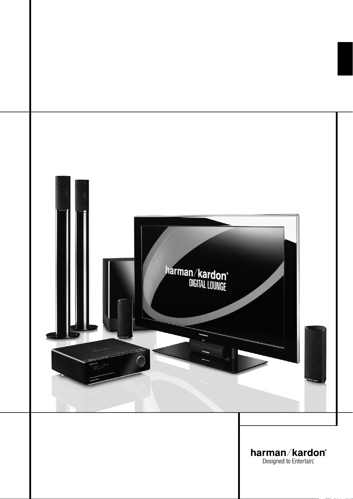
Harman Kardon Digital Lounge 632, 640, 646
OWNER’S MANUAL
ENGLISH
Page 2
Table of Contents
Page
3 Introduction
4 Safety Information
5 Installation Location, Cleaning, Unpacking
6 Terminology
7 Features
8 Front Panel Controls
9 Front Panel Display
10 Rear Panel Connections
12 Rear Panel Connections TV
14 Remote Control
17 Second Remote Control
18 Basic Information
18 About This Manual
18 Regional Coding
System Connection
19 Installation and Connections
19 Equipment
19 Optional Set Top Box or Cable Box Connections
20 Connecting a PC
20 Connecting a Digital Set Top Box or Satellite
Receiver
20 Optional Audio Connections
20 Speaker Placement
21 Screen Placement
21 Connecting AC Power
21 First Turn On
Playback Basics
21 Automatic Channel Search
22 Digital Tuner
23 Basic Playback
24 Disc Playback Features
24 Skipping tracks or titles/chapters
24 Fast Motion Playback/Fast Search
24 Freeze Frame and Frame Advance (with DVD only)
24 Slow Motion Playback (with DVD only)
24 About DivX Movie Files
25 Surround Mode
System Setup
25 System Defaults
25 General Functionality of the User Interface
25 Setup Menu for Screen
26 TV Setup
27 Analog TV Search
28 DVD Setup
28 Picture Calibration
28 HDMI Setup
29 DVI Setup
29 Component, S-Video, Composite, Scart 1 and
Scart 2 Setup
29 General Setup
30 Sound Set Up
30 Setup Menu for DVD Receiver
30 System Settings
30 Display Language
30 Preferred Subtitle Language
30 Panel Time-Out
30 Status Bar Time-Out
30 Parental Control
30 Disc Recognition
30 PBC Support
30 Screen Saver
30 Show Angle Icon
30 Audio Settings
30 Preferred Audio Language
31 Dynamic Range
31 Delay Unit
31 Tone Control
31 Bass Level
31 Treble Level
31 DVD Sound Mode
31 Audio Adjustment
31 Automated Speaker Setup (EzSet/EQ)
34 Manual Speaker Setup
34 Delay
34 Video Settings
34
Video Mode
34 Video Resolution
35 DivX Video On Demand
Test Screen
36 Picture Calibration with Test Disc
Player Menu
37 Using the Status Bar Menu
37 On Screen Display Menus
37 Disc Player Menu
38 Information Displays
38 Programmed Play
Radio Menu
38 Radio Menu
39 Rearranging the station list
39 Selecting presets
39 Removing presets
39 RDS Station ID
39 Surround Mode for Tuner
TV Menu, AUX Menu, Digital
In Menu
40 TV Menu
40 AUX Menu
40 Digital In Menu
USB Menu, The Bridge
41 USB Menu
41 The Bridge
42 Surround Mode Chart
TV Functions
43 TV Functions
43 Changing Channels
43 Picture-In-Picture (PIP) Function
43 Aspect Ratio
44 Teletext
Remote Control
44 Learning Codes
45 Erasing Learned Codes
DVD Languages Codes
46 Languages Codes
Troubleshooting
47 Troubleshooting
Glossary
49 Glossary
Specifications
50 Specifications
Declaration of Conformity
We, Harman Consumer Group, Inc.
2, route de Tours
72500 Château-du-Loir,
FRANCE
declare in own responsibility, that the product described
in this owner’s manual is in compliance with technical
standards:
EN 55013:2001 + A1:2003
EN 55020:2002 + A1:2003
EN 61000-3-2:2000
EN 61000-3-3:1995 + A1:2001
EN 60065:2002
Jurjen Amsterdam
Harman Consumer Group, Inc.
03/08
Typographical Conventions
In order to help you use this manual with the remote control, front-panel controls and rear-panel
connections, certain conventions have been used.
EXAMPLE – (bold type) indicates a specific remote control or front-panel button, or rear-panel
connection jack
EXAMPLE – (OCR type) indicates a message that is visible on the front-panel information display
– (number in a square) indicates a specific front-panel control
– (number in a circle) indicates a rear-panel connection
0
– (number in an oval) indicates a button or indicator on the main remote control
A – (letter in a square) indicates an indicator on the front panel display
A
– (letter in a circle) indicates a rear-panel connection on the TV
A
– (letter in an oval) indicates a button on the small remote control
The appearance of the text or cursor for your receiver’s on-screen menus may vary slightly from
the illustrations in this manual. Whether the text appears in all uppercase or upper- and lowercase
characters, performance and operation remain the same.
2 TABLE OF CONTENTS
Page 3
Introduction
2
Thank you for choosing Harman Kardon!
With the purchase of a Harman Kardon Digital
Lounge system you are about to begin many
years of listening enjoyment.
Designed to provide all the excitement and detail
of movie soundtracks, every nuance of musi cal
selections and crystal clear video playback, the
Digital Lounge system is truly a complete
audio/video system for the new millennium.
The Digital Lounge system has been engineered
so that it is easy to take advantage of all the
power of its digital technology. To obtain the
maximum enjoyment from your new system, we
urge you to read this manual. A few minutes
spent learning the functions of the various controls will enable you to take advantage of all the
power the Digital Lounge system is able to deliver.
If you have any questions about this product, its
installation or its operation, please contact your
retailer or custom installer. They are your best
local sources of information.
Description and Features
The Digital Lounge system is among the most
complete and versatile home cinema systems.
It incorporates a range of carefully designed,
sophisticated integrated system components that
combine an Audio Video Controller, DVD Audio
player, a flat panel TV, 5.1 loudspeaker system
and floor stands.
Harman Kardon Digital Lounge system offers our
well-known audio and video performance and
ease of use, together with complete control via
one dedicated system remote control.
In addition to Dolby Digital and DTS decoding for
digital sources, the Dolby Pro Logic II mode for
Matrix surround-encoded or Stereo recordings is
available for use with sources such as CD, VCR,
TV broadcasts and the system's own FM tuner as
well as the latest 5.1 channel versions of
Harman's own Logic 7
®
technology.
To enable you to get the maximum quality from
DVDs, the Digital Lounge system is equipped
with the latest in design techniques, including a
High Definition Multimedia Interface delivering
the finest quality digital video transmitted over
one single cable from the Harman Kardon Digital
Lounge receiver/DVD-Audio player to the
Harman Kardon Digital Lounge display. The oneway HDMI connection will allow you to watch
your blockbuster movies in a high resolution up
to 720p or 1080i. A DVI input to connect a PC is
available too, as well as multiple HDMI inputs.
The 40" and 46" displays are both Full HD
displays, fully compliant with future HD signals,
ready to bring the latest technology for clearer
and sharper pictures into your home. The 32"
version is HD Ready.
With one simple connection between the Digital
Lounge and the Harman Kardon , you
are able to listen to audio files stored on your
compatible Apple
even let you charge your iPod.
An important addition to the Digital Lounge's
impressive list of features is EzSet/EQ
automates the configuration process to make it
quicker, easier and more precise. Using the special microphone supplied with the unit, EzSet/EQ
takes the guesswork out of entering speaker
“size” and crossover information, delay times for
all channels and output levels. In addition to the
configuration settings, EzSet/EQ also includes
room equalization so that the signals sent to
each speaker are tailored to provide accurate
sonic quality with your specific combination of
speaker type, room size and other factors that
influence room acoustics. With EzSet/EQ, your
system is custom-configured in a few minutes
with accuracy that previously required expensive
and hard-to-use test equipment.
Along with conventional Video and CD audio
discs, the Digital Lounge system is also
compatible with MP3, CD-R and CD-RW as well
®
as DivX
®
iPod®**. The Bridge™will
and VCD discs.
™
, which
As portable USB devices increase in popularity,
Harman Kardon's Digital Lounge system is
among the first integrated home theater system
that allows mobile interconnectivity by playing
compatible music or image files from portable
devices via two USB On-The-Go inputs.
A wide range of programming features makes it
easy to program an evening’s worth of entertain ment. When playing DVDs, easy-to-understand
on-screen menus and icons make it simple to
change languages, soundtracks, subtitles or
aspect ratio, while a parental-lock function
enables you to control which discs may be
viewed by younger members of the house hold.
For total user convenience, Harman Kardon
Digital Lounge offers a system remote control,
ready to operate the screen, the DVD player and
the receiver. Besides the standard full function
remote control used for initial setup and system
calibration, Harman Kardon offers a second and
smaller remote control. By limiting the buttons
on this remote control to those that will be used
during every day use, system control becomes
extremely easy and pleasant.
n Plays a Wide Range of Video and Audio
Formats, Including DVD-Video Discs,
VCD, Standard CD Audio Discs, CD-R/RW,
DVD-R/RW, DVD-+R/RW, Audio Discs and
MP3 Discs
n DVD-Audio Playback for Richer Detail,
Expanded Dynamic Range and Improved
Realism
n HDMI One-wire Digital Video Connection
between the Screen and the Controller
n Extensive Speaker Setup Options with,
Output Level Adjustment and Delay
Settings
n High-Quality Video Playback 10-Bit
DACs, Progressive Scan
n Independent Picture Calibrations for
Each Individual Input
ENGLISH
NOTE: This player is designed and manufactured for compatibility with Region Management
Information that is encoded on most DVD discs. This player is designed only for playback of discs
with Region Code 2, or for discs that do not contain Region Code infor mation. If there is any other
Region Code on a disc, that disc will not play on the DVD.
INTRODUCTION 3
Page 4
Introduction
Safety Information
n Advanced Analog Signal Conversion
(AASC) Technology
n Automatic TV Channel Search
n Full HD (HD Ready on the DL 632)
with 4 HDMI and DVI inputs
n High-bandwidth Digital Content
Protection (HDCP)
n Built-in DVB-T Tuner and integrated
Multi Standard TV tuner with Picture in
Picture (PIP) and Teletext
n Easy-to-Use On-Screen Navigation
System
n Playback of MP3 and Windows
®
WMA
Audio Discs and JPEG image files
n Harman Kardon’s exclusive Logic 7
®
processing
n Harman Kardon’s advanced EzSet/EQ
™
automatically configures speaker
settings and sets room equalization for
quick, easy and accurate system setup
n Connects to Harman Kardon’s
(optional) for charging, playback and
control of a compatible Apple
®
iPod
®
device
n Simultaneous Playback of MP3 and
JPEG files
n Side- and rear-panel USB On-The-Go
connections for playing compatible
music or image files from portable
devices
n Extensive Programming Capability for
Audio and Video Discs
n Parental Lock Controls Prevent
Unauthorized Viewing of Restricted
Movies
n Playback of DivX compressed video files
n Multiple Options for Language,
Soundtrack and Subtitle Selection
n Multiple-Angle Capabilities With
Specially Encoded DVD Discs
n Ergonomically Designed Remote
Controls
n Multiple digital inputs and outputs
n Multiple Analog Inputs and Outputs
n High Definition On-screen menu and
display system
n Subwoofer Trigger to Control
Subwoofer On/Off
IMPORTANT NOTES:
This manual describes the working of your
complete Harman Kardon Digital Lounge system,
and replaces the individual manuals found in
some of the components of your system.
Only use the Digital Lounge system controller
with the loudspeaker system supplied. Failure to
do so may cause damage to either the controller
or the loudspeakers and will invalidate any
warranty.
All of the optional system settings have been
pre set at our factory for correct operation of the
system. All you have to do is insert a disc, sit
back, and enjoy a great home theater
experience.
You may want to change some of the op tion al
set tings. A description of all the optional set tings
and in struc tions for changing them are found in
the second half of the manual.
This system was designed to provide you with
many years of reliable operation with a minimum
of care and main te nance. Every component in
your system was in perfect working con di tion
when it left our fac to ry. If you ex pe ri ence any
problems with the set-up or operation of this
system, please review the Troubleshooting Guide
at the end of this manual before you con tact
your authorized Harman Kardon dealer.
Important Safety Information
Verify Line Voltage Before Use
Your Digital Lounge system has been designed
for use with 220-240-Volt AC current.
Connection to a line voltage other than that for
which it is intended can create a safety and fire
hazard and may damage the system.
If you have any questions about the voltage
requirements for your specific model, or about
the line voltage in your area, contact your dealer
before plugging the unit into a wall outlet.
Do Not Use Extension Cords
To avoid safety hazards, use only the power
cords attached to your system components. We
do not recommend that extension cords be used
with this product. As with all electrical devices,
do not run power cords under rugs or carpets or
place heavy objects on them. Damaged power
cords should be replaced immediately by an
authorized service depot with a cord meeting
factory specifications.
Handle the AC Power Cord Gently
When disconnecting the power cord from an AC
outlet, always pull the plug, never pull the cord.
If you do not intend to use the system for any
considerable length of time, disconnect the plug
from the AC outlet.
Do Not Open the Cabinet
There are no user-serviceable components inside
the system components. Opening the cabinets or
rear panels may present a shock hazard, and any
modification to the system components will void
your guarantee. If water or any metal object
such as a paper clip, wire or a staple accidentally
falls inside the system components, disconnect
them from the AC power source immediately,
and consult an authorized service station.
4 INTRODUCTION
Page 5
Safety Information
Installation Location
n To assure proper operation and to avoid the
potential for safety hazards, place the system
components on a firm and level surface. When
placing any of the system components on a
shelf, be certain that the shelf and any
mounting hardware can support the weight of
the product.
n Make certain that proper space is provided both
above and below the system components for
ventilation. If this product will be installed in a
cabinet or other enclosed area, make certain
that there is sufficient air movement within the
cabinet. Under some circumstances a fan may
be required.
n Do not place the system components directly
on a carpeted surface.
n Avoid installation in extremely hot or cold
locations, or an area that is exposed to direct
sunlight or heating equipment.
n Avoid moist or humid locations.
n Do not obstruct the ventilation slots on the
top of the system components, or place
objects directly over them.
n The display surface of the screen is sensitive to
pressure and scratching. Treat the display surface with care in order to avoid lasting damage.
n If the screen is brought into its operating room
from cold surroundings, condensation can
occur. Wait until the device has reached room
temperature and is absolutely dry before you
put it into operation.
n The screen will set itself automatically to a
mains voltage in the range of 100 V to 240 V.
Ensure that the local mains voltage does not
exceed and is not less than this range.
n The screen may be connected to an earthed
mains outlet only.
n The On-Off switch does not disconnect the set
from the mains voltage. For complete disconnection from the mains voltage you must pull
out the mains plug.
n The set must be disposed of as special waste
in accordance with your local waste disposal
regulations. The safety regulations that apply
to luminous materials have to be taken into
account for handling and disposal purposes.
n The backlight of the LCD TV contains mercury.
The safety regulations that apply to
fluorescent tubes have to be taken into
account for handling and disposal purposes.
n For PC operation use a screen saver with
moving pictures and activate the power
management for your display to avoid screen
”burns” being caused by still pictures.
Cleaning
When the system components gets dirty, wipe it
with the soft, dry cloth and the special
ScreenClean liquid that is supplied with your
Harman Kardon Digital Lounge product. NEVER
use benzene, aerosol cleaners, thinner, alcohol or
any other volatile cleaning agent. Do not use
abrasive cleaners, as they may damage the finish
of metal parts. Avoid spraying insecticide near
the system components.
Moving the Unit
Before moving the system components, be certain to disconnect any interconnection cords with
other components, and make certain that you
disconnect the components from the AC outlet.
Unpacking
Before unpacking the screen, please take the
protective white gloves from the accessory tool
box. These gloves allow you to unpack the screen
without damaging the screen and its high gloss
finish.
The carton and shipping materials used to protect your new DVD player/receiver, TV and loudspeakers during shipment were specially
designed to cushion it from shock and vibration.
We suggest that you save the carton and packing
materials for use in shipping if you move, or
should the components ever need repair.
To minimize the size of the carton in storage, you
may wish to flatten it. This is done by carefully
slitting the tape seams on the bottom and collapsing the carton. Other cardboard inserts may
be stored in the same manner. Packing materials
that cannot be collapsed should be saved along
with the carton in a plastic bag.
If you do not wish to save the packaging materials, please note that the carton and other sections of the shipping protection are recyclable.
Please respect the environment and discard
those materials at a local recycling center.
Copyright
Audio-visual material may consist of copyright
works which must not be recorded without the
permission of the owner of the copyright.
Please refer to relevant laws covering copyright
protection.
Copy protection
This DVD player supports Macro vision copy protection. On DVD discs that include a copy protection code, if the contents of the DVD disc are
copied using a VCR, the copy pro tecti on code prevents the videotape copy from playing normally.
For Optimum Performance
The controller is a precision device that is constructed using extremely accurate technology.
Soiling or friction affecting the pickup lens or disc
drive can impair the image quality. In the worst
case, neither video nor audio will be played back.
To obtain optimum picture quality, the player
should be checked (cleaning and replacement of
some parts) every 1,000 hours. Note that this period varies depending on the environment (temperature, humidity, dust) in which the player is used.
Do not attempt to clean the pickup lens
yourself.
ENGLISH
SAFETY INFORMATION 5
Page 6

Terminology
Terminology
Since they share some of the characteristics and
technology of CD players, many of the terms and
operational concepts used in a DVD player are
similar to what you may be familiar with from CD
players and changers, or older video disc formats
such as Laser Disc. However, if this is your first
DVD product, some of the terms used to describe
the features of a DVD player may be unfamiliar.
The following explanations should solve some of
the mysteries of DVD, and help you to enjoy all
the power and flexibility of the DVD format and
the DVD.
With the arrival of DVD, disc data capacity has
increased dramatically. On a DVD Video disc most
of this capacity is taken up by MPEG 2 video and
the multichannel movie soundtrack in Dolby
Digital and/or DTS. This information is
compressed.
Full HD and HD Ready
High Definition (HD) is the future broadcast standard, delivering much higher video resolution. The
"HD ready" logo is introduced by the European
Industry Association for Information Systems
(EICTA). It is a quality sign for the differentiation
of display equipment, capable of processing and
displaying these new HD signals, awarded on the
basis of minimum functionality requirements.
High Definition Multimedia Interface
(HDMI): HDMI has emerged as the digital
standard for connecting High Definition devices,
displays and components, and provides for the
pristine transmission of high-definition digital
video. HDMI is the first and only digital interface
for Consumer Electronics devices that can carry
uncompressed high-definition video, and command data, allowing customers to obtain pure
digital high-definition video.
Digital Visual Interface™ (DVI) Input
The DVI input provides a high speed, digital connection for visual data types. The interface is primary focused at providing a connection between
a computer and the display.
High-bandwidth Digital Content Protection
(HDCP)
HDCP is a specification developed to protect digital entertainment content across the DVI/HDMI
interface. The HDCP specification provides a
robust, and transparent method for transmitting
and receiving digital entertainment content from
our Harman Kardon Cinema Lounge DVDAudio/Video player to the DVI/HDMI-inputs on the
Harman Kardon Digital Lounge display.
USB On-The-Go: Due to its widespread acceptance, USB is becoming the de facto industry standard for connecting peripherals to PCs and laptops. Many of the new peripherals using USB are
also portable devices.
As these portable devices increase in popularity,
there is a growing need for them to communicate
directly with each other when a PC is not available, for instance in consumer electronics products. The USB On-The-Go technology addresses
this need for mobile interconnectivity.
Title: For a DVD, a title is defined as an entire
movie or program. There can be as many chapters
within a title as the producers decide to include.
Most discs include only one title, but some may
have more than one, to give you a “Double
Feature” presentation.
Chapter: DVD programs are divided into
chapters and titles. Chapters are the sub-sections
programmed into a single title on a disc. Chapters
may be compared to the individual tracks on an
audio CD.
Progressive scan: Due to the immense data
storage capacity of DVD, images are nowadays
stored progressively (intact, rather than interlaced).
This allows all of the lines in each frame (odd and
even) to be shown at the same time. Harman
Kardon Digital Lounge comes with true progressive scan video output resulting in a 40% greater
light output than a conventional TV and a stunningly detailed, high definition image with absence
of visible scanlines and motion artifacts.
Advanced Analog Signal Conversion (AASC)
Technology
Standard definition analog TV tuners broadcast an
image of 576 lines; LCD screens have a resolution
that have much more available scan lines. If an
analog tuner signal is not handled appropriately,
the picture quality of analog tuner signals on
higher definition screens risks looking distorted,
with pixels being clearly visible, sharp edges and a
loss of definition.
Our systems use Advanced Analog Signal
Conversion technology to optimize the picture
coming from analog tuners. The result is a very
defined and smooth picture that is comparable
with digital images coming from higher resolution, digital tuners.
DVB-T
DVB-T stands for Digital Video Broadcasting Terrestrial and it is the European consortium standard for the broadcast transmission of Digital terrestrial television.
Multiple Angle: DVDs have the capability to
show up to four different views of the same scene
in a program. When a disc is encoded with multiple-angle information, pressing the Angle button
will enable you to switch between these different
views. Note that at present, few discs take advantage of this capability and, when they do, the multiple-angle technology may only be present for
short periods of time within the disc. Producers
will usually insert some sort of icon or graphic in
the picture to alert you to the availability of multiple viewing angles.
Reading: This is a message that you will see after
you´ve loaded the disc. It refers to the fact that
the player must first examine the contents of the
disc to see if it is a CD or DVD, and then extract
the information about the type of material on the
disc, such as languages, aspect ratios, subtitles,
number of titles and more. The slight delay while
the contents of the disc are read is normal.
Resume: The operation of the Stop Button on the
DVD works differently from what you are used to
on CD players. On a traditional CD player, when
you press the Stop button, the unit does just that:
it stops playback. On a CD player, when you press
the start button again, the disc starts from the
beginning. With the DVD, however, you have two
options when playing DVD discs. Pressing Stop
once will stop playback, but it actually puts the
unit in the Resume mode. This means that you can
turn the machine off and, when you press play the
next time, the disc will resume or continue from
the point on the disc where the Stop button was
pressed. This is helpful if you are watching a
movie and must interrupt your viewing session
but wish to pick up where you left off. Pressing
the Stop button twice will stop the machine in a
traditional manner and, when the disc is played
again, it will start from the beginning.
In resume mode, the cover of the DVD will be
displayed, if available. Otherwise, the
Harman Kardon screen will appear.
DivX
DivX is the name of a new video codec which is
based on the MPEG-4 compression standard for
video. This DVD player will playback discs created
with DivX software. The DVD player’s playback
functionalities of DivX video discs will vary
depending on the DivX software version used for
creating your movies. For more information about
the different software versions of DivX, please go
to www.divx.com.
6 TERMINOLOGY
Page 7
Features
High quality video
• High Definition Multimedia Interface (HDMI)
for a single wire, digital connection to your
screen.
• Digital Visual Interface (DVI) provides a high
speed, digital connection between a computer
and the screen.
• Advanced sophisticated 10-bit MPEG-2 video
decoding circuits.
• Progressive Scan component video ouputs
(NTSC and PAL)
• DVB-T for digital terrestrial television broadcast.
• Advanced Analog Signal Conversion (AASC)
Technology for optimized pictures coming from
analog tuners.
• Test screen videos available for testing video
performance and setup.
• Pure PAL with NTSC disc due to true
NTSC/PAL conversion.
• Dual-layer compatibility for extended play
DVD.
• Playback of JPEG image files
High quality digital audio
• High quality 5.1 digital surround sound from
DVD-Audio, DTS or Dolby Digital discs.
• With linear PCM audio at 16-24 bits and
44-96 kHz, audio quality exceeding that of CD
becomes possible.
• Coaxial digital audio output.
Many convenient features
• On-Screen Menu lcons for disc information or
player information and access to many major
functions of this unit.
• EzSet/EQ automatic calibration.
• Thumbnails for easy search of image files.
• Subtitles may be displayed in one of numerous
languages*.
• The multi-angle function allows you to choose
the viewing angle of scenes which were shot
from a number of different angles (Limited to
DVD’s recorded with multiple camera angles.)
• Multiple options for dialog language and
soundtrack selection (limited to DVD’s
recorded with multiple dialog languages or
soundtracks).
• Intuitive menu operating system.
• 4 step Zoom during play and pause.
• Backlit, ergonomically designed main remote
control and a second, smaller remote control
for day to day usage.
• Future software upgrades accessible via
Internet. (See information below.)
* The number of languages recorded depends
on the software.
Compatible with CD
as well as DVD
• The Digital Lounge system will play any
conventional Audio CD or recordable (CD-R) or
erasable CD (CD-RW), MP3, WMA (v9) or any
DivX or VCD or DVD-Audio and DVD-Video
with the region code 0 or 2.
Disc formats supported
by this player
The unit can play the following disc formats
(8 cm and 12 cm size):
• DVD
• DVD-AUDIO
• DVD-R
• DVD-RW
• DVD+R
• DVD+RW
• CD
• CD-R
• CD-RW
• VCD
• S-VCD
• WMA (v9)
• DivX and XviD
NOTE: Due to differences in the format of
certain discs, it is possible that some discs may
include a mix of features that are not compatible
with the DVD. Similarly, although the DVD is
capable of a wide range of features, not all discs
include every capability of the DVD system. For
example, although the DVD is compatible with
multi-angle discs, that feature is only possible
when the disc is specially encoded for multi pleangle play. In addition, the DVD is capable of
playing back both Dolby Digital and DTS soundtracks, but the number and types of tracks
available will vary from disc to disc. To make
certain that a specific feature or soundtrack
option is available, please check the options
noted on the disc jacket.
n Playback capability for CD-R, CD-RW, WMA,
JPEG, MP3, DivX, VCD/SVCD, DVD-R, DVD+R,
DVD-RW and DVD+RW discs may vary due to
variations in the quality of the disc and the
recorder used to create the disc.
n The Digital Lounge system is compatible with
most discs recorded with files encoded using
MP3 or Windows Media 9, as well as JPEG
still images. However, note that variations in
the encoder or codec used and the bit rate of
the encoding may affect the Digital Lounge
system's ability to play back a specific disc. As
a result, we cannot guarantee complete compatibility with all encoders and versions of the
codecs. For best results, we recommend that
MP3 files be encoded at bit rates ranging
between 32kbps and 320kbps. WMA files
should be encoded at bit rates between
64kbps and 320kbps. Although the Digital
Lounge systems is capable of playing some
WMA 9 files, not all features of version 9 are
supported. JPEG Files should not be created
with the SRGB or CMYK mode.
Upgradeability via Internet
The ”firmware” controlling the functionality of
the Harman Kardon Digital Lounge system is
fully upgradeable. In the event of future
improvements to its operations and features,
it will be possible to download firmware
upgrades from
www.harmankardon.com/International/
All you have to do is create a CD-R with the
data and insert it in the DVD for an automatic
upgrade. You can also load the upgrade on a
portable mass storage device to connect to any
of the two USB inputs.
Packing List
1 Harman Kardon Digital Lounge system DVD
Player/Controller
1 Harman Kardon HKTS 11 Home Theater
Speaker System
1 HT 32EX, HT 40HD or HT 46HD LCD TV
1 Harman Kardon HTFS 2 Loudspeaker Stands
Tool Kit:
1 Main remote control
1 Day-to-day use remote control
1 Owner's manual
1 Safety booklet
6 Batteries
1 HDMI - SP-DIF - Remote In/Out cable
1 Drilling jig
1 ScreenClean kit
2 Pair of gloves
1 DVD with test material
1 Pair of calibration glasses
1 After sales card
ENGLISH
FEATURES 7
Page 8
Digital Louge
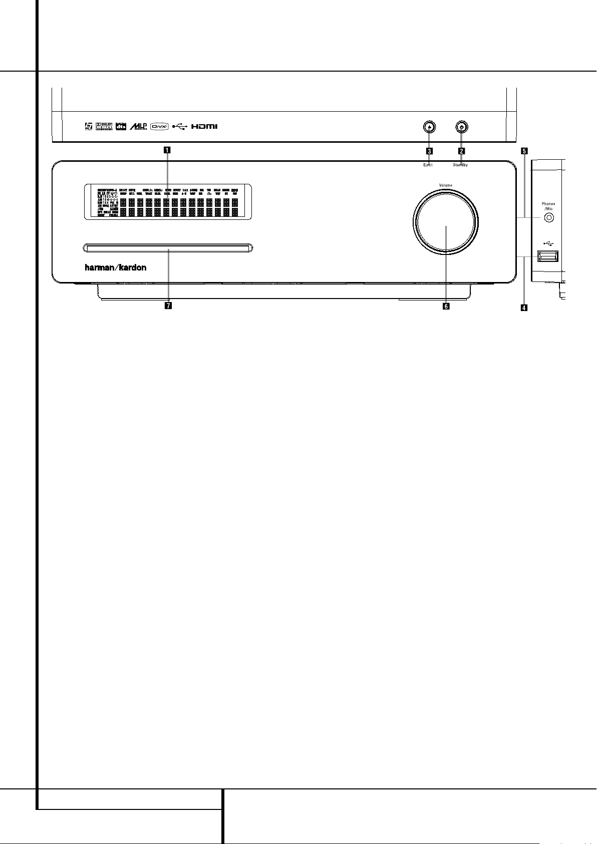
Front Panel Controls
Main Information Display
1
Power On/Off (Standby)
2
Open/Close
3
USB On-The-Go Input
4
Headphone Jack
5
Volume Control
6
Slot Loader
Main Information Display: This display
delivers messages and status indications to help
you operate the Digital Lounge Controller.
1
Power On/Off (Standby): Press the button
once to turn the Digital Lounge Controller on,
press it again to put the unit in the Standby
mode.
Note that when the Digital Lounge Controller is
switched on, the Power Indicator around the
button turns blue.
2
Eject: Press this button to release a disc
from the loader.
3
USB On-The-Go Input: This input may be
used to temporarily connect a USB thumb device
or portable hard disk for direct playback of
audio, image of video files or a USB hub. The
USB inputs are designed to power a single USB
device at a time. If additional hard disks are
connected through a hub it is necessary that
additional external power supplies are used to
power the hub and hard disks.
4
Headphone Jack: This jack may be used to
listen to the system's output through a pair of
headphones. Be certain that the headphones
have a standard 3.5 mm stereo phone plug.
Note that the main room speakers will
automatically be turned off when the
headphone jack is in use.
When configuring your system using EzSet/EQ,
the calibration microphone should be plugged
into this jack
5
Volume Control:Turn this knob clockwise
to increase the volume, counterclockwise to
decrease the volume. If the system is muted,
adjusting volume control will automatically
release the unit from the silenced condition.
4
.
6
Slot loader: Gently insert a CD or DVD into
this slot, with the printed side of the disc facing
up. Note there is no drawer. Press the Eject
Button
2
to release the disc
8 FRONT PANEL CONTROLS
Page 9
Front Panel Display
ENGLISH
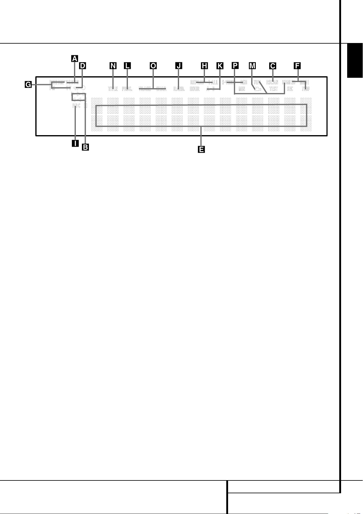
A Disc Type Indicators
B Playback-Mode Indicators
C Progressive Scan Indicator
D Parental Lock Indicator
E Time Indicators
F Video Format Indicators
A Disc Type Indicators: The CD or DVD
indicator will illuminate to show the type of disc
currently being played.
B Playback-Mode Indicators: These
indicators light to show the current playback
mode:
N
Lights when a disc is playing in the normal
mode
H
Lights when the disc is in the Fast Search
Forward mode. The on-screen banner display
indicates the selected speed (2x, 8x, 16x, 100x).
1
Lights when the disc is paused.
G
Lights when the disc is in the Fast Search
Reverse mode. The on-screen banner display
indicates the selected speed (2x, 8x, 16x, 100x).
C Progressive Scan Indicator: This indicator
lights when the unit sends out a progressive
scan signal.
D Parental Lock Indicator: This indicator
lights when the parental-lock system is engaged
in order to prevent anyone from changing the
rating level without a code.
G Source Indicators
H Repeat Indicators
I VCD Playback Control Indicator
J Random Indicator
K A-B Repeat Indicator
L Program Indicator
E Time Indicators: These positions in the
indicator will show the running time of a DVD in
play. When a CD is playing, these indicators will
show the current track time, time remaining in
the current track, or the total remaining time on
the disc. When an iPod is playing, the display
will show the elapsed and remaining time on the
top line. The bottom line will scroll information
about the song, title, album and artist.
NOTE: The Indicators NOE will also display
text messages about the DVD’s status, including
Reading when a disc is loading,
STANDBY when the unit is turned off, and
Disc Error when a disc not compatible
with the DVD is put into the play position.
F Video Format Indicators: These indicators
will represent the video format currently playing.
G Source Indicators: These indicators will
light to show which source is currently selected.
H Repeat Indicators: These indicators light
when any of the Repeat functions are in use.
M Angle Indicator
N Title Indicators
O Chapter/Track Number Indicators
P Video Output Indicators
I VCD Playback Control Indicator: This
indicator lights when the playback control
function is turned on with VCDs.
J Random Indicator: This indicator lights
when the unit is in the Random Play mode.
K A-B Repeat Indicator: This indicator lights
when a specific passage for repeat playback has
been selected.
L Program Indicator: This indicator lights
when the programming functions are in use.
M Angle Indicator: This indicator blinks when
alternative viewing angles are available on the
DVD currently playing.
N Title Indicators: These two positions in the
display will show the current title number when
a DVD disc is playing.
O Chapter/Track Number Indicators: When
a DVD disc is playing, these two positions in the
display will show the current chapter. When a
CD disc is playing they will show the current
track number.
P Video Output Indicators:These indicators
will represent the active video output. .
FRONT PANEL DISPLAY 9
Page 10
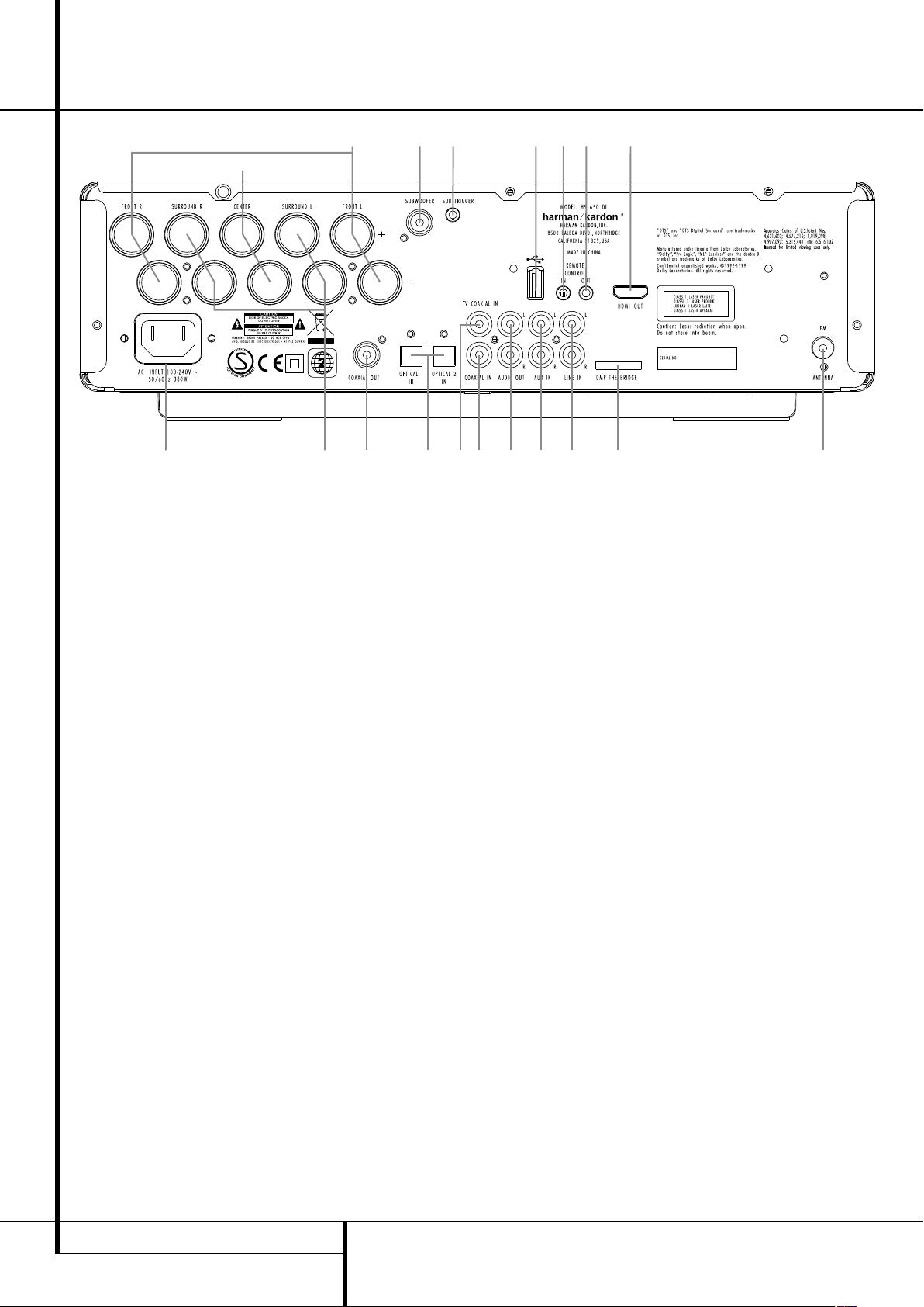
Rear Panel Connections
0
C
123F7B
4E
D
98GA6I H 5
HDMI Output
Remote IR Output
Remote IR Input
USB On-The-Go Input
AC Power Cord
FM Antenna
Audio In
Subwoofer Output
Coaxial Digital TV Input
Optical Digital Input
Analog Audio Outputs
Front Speaker Outputs
Center Speaker Outputs
Surround Speaker Outputs
Coaxial Digital Output
Subwoofer Trigger Output
Coaxial Digital Input
DMP The Bridge Input
Analog Audio Inputs
HDMI Output: Connect this output to the
J
HDMI input
of the screen, using the supplied
HDMI - SP-DIF - Remote In/Out cable.
Remote IR Output: This connection permits the IR sensor in the receiver to serve other
remote controlled devices. Connect this jack to
the “IR IN” jack on Harman Kardon or other
compatible equipment. Note this connection is
only necessary for optional, additional products
connected to the player. It is not necessary for
proper control of the Digital Lounge system.
Remote IR Input: Connect this input to the
U
Remote IR Output
of the TV, using the special
HDMI - SP-DIF - Remote In/Out cable. This will
allow you to control all components in your system by pointing the remote control to the TV
only.
USB On-The-Go Input: This input may be
used to temporarily connect a USB thumb device
or portable hard disk for direct playback of
audio, image of video files, a digital photo camera or a USB hub.
AC Power Cord: Connect this plug to an
AC outlet. If the outlet is controlled by a switch,
make certain that it is in the ON position.
FM Antenna: Connect to the supplied FM
antenna.
Audio In: Connect to a line-level analog
audio source: TV, tape player, Minidisc, PC, etc.
Subwoofer Output: Connect to the
SUB/LFE input on the subwoofer.
Coaxial Digital TV Input: Connect the
H
Coax Digital TV Output
of the screen to this
jack, using the supplied HDMI - SP-DIF - Remote
In/Out cable.
Optical Digital Input: Connect the optical
digital output from a DVD player, HDTV receiver,
LD player, MD player, satellite receiver or CD
player to this jack. The signal may be either a
Dolby Digital signal, DTS signal or a standard
PCM digital source.
Analog Audio Outputs: Connect these
jacks to the RECORD/INPUT jacks of an optional
audio recorder for recording.
Front Speaker Outputs: Connect these
outputs to the matching + or – terminals on
your left and right speakers. In conformance with
the new CEA color code specification, the White
terminal is the positive, or "+" terminal that
should be connected to the red (+) terminal on
Front Left speaker with the older color coding,
while the Red terminal is the positive, or "+"
terminal that should be connected to the red (+)
terminal on Front Right speaker. Connect the
black (–) terminals on the Digital Lounge system
to the black (–) terminals on the speakers. See
page 19 for more information on speaker polarity.
Center Speaker Outputs: Connect these
outputs to the matching + and – terminals on
your center channel speaker. In conformance
with the new CEA color code specification, the
Green Terminal is the positive, or "+" terminal
that should be connected to the red (+) terminal on speakers with the older color coding.
Connect the black (–) terminal on the Digital
Lounge system to the black negative (–) terminal
on your speaker. (See page 19 for more information on speaker polarity.)
10 REAR PANEL CONNECTIONS
Page 11
Rear Panel Connections
Surround Speaker Outputs: Connect
these outputs to the matching + and – terminals
on your surround channel speakers. In conformance with the new CEA color code specification, the Blue terminal is the positive, or "+" terminal that should be connected to the red (+)
terminal on the Surround Left speaker with older
color coding, while the Gray terminal should be
connected to the red (+) terminal on the
Surround Right speaker with the older color coding. Connect the black (–) terminal on the Digital
Lounge system to the matching black negative
(–) terminals for each surround speaker. (See
page 19 for more information on speaker
polarity.)
Note: You’ll find more details about all
Audio/Video connections under Setup and
Connections on the following pages.
Coaxial Digital Output: Connect this jack
to the matching digital input connector on a
digital recorder such as a CD-R or MiniDisc
recorder.
Subwoofer Trigger Output: Connect this
trigger output to the trigger input of the
Harman Kardon subwoofer, so that the subwoofer will switch on and off at the same time
as the rest of the system.
Coaxial Digital Input: Connect the coaxial
digital output from a DVD player, HDTV receiver,
LD player, MD player, satellite receiver or CD
player to this jack. The signal may be either a
Dolby Digital signal, DTS signal or a standard
PCM digital source.
Connector: With the Digital Lounge turned off,
connect one end of the optional Harman Kardon
other to your compatible Apple iPod. When the
Digital Media Player source is selected, you may
view your iPod’s control and navigation
messages on your video display and in the
Upper and Lower Display Lines E. You may
navigate the iPod and select tracks for playback
using the
Enter Button
Analog Audio Inputs: Connect these jacks
to the analog audio output on a TV set or external audio system for analog audio playback.
Digital Media Player (DMP)
to this proprietary connector, and the
⁄/¤/‹/›
Buttons9and the
6
.
ENGLISH
REAR PANEL CONNECTIONS 11
Page 12
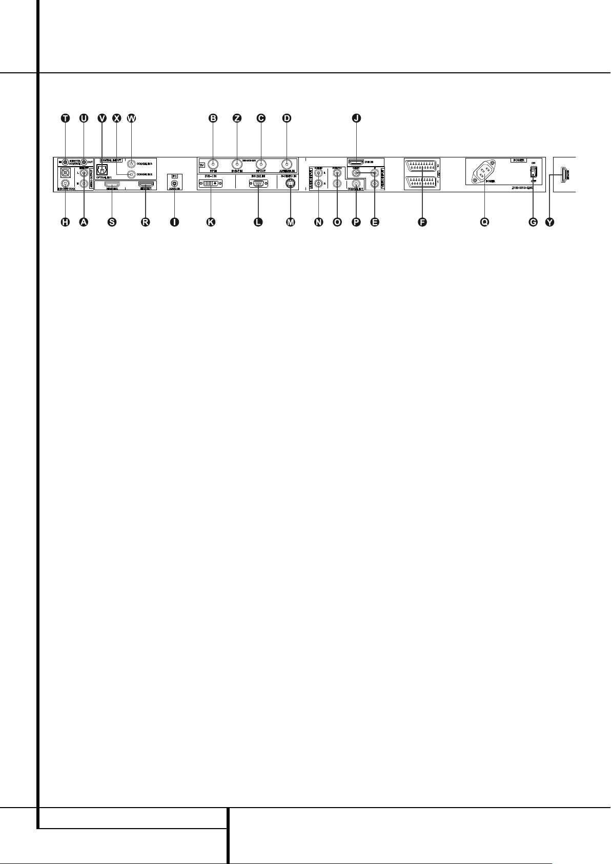
Rear Panel Connections TV
A
Audio Output
B
RF Antenna Input
C
RF Antenna Output
D
Antenna Input
E
Component Video Inputs
(and Composite Video Input)(CVBS/Y)
F
Scart Inputs
G
Power On/Off Switch
H
Coaxial Digital TV Output
A
Audio Output: These jacks have no direct
function in the system. They will output the
internal audio signal of the screen, either from
its tuner or an external source connected to any
other input.
B
RF Antenna Input: Keep the attached
patch cord connected to the RF Antenna
C
Output
C
patch cord connected to the RF Antenna
Input
D
terrestrial antenna or cable to this input.
E
(and Composite Video Input):These jacks
have no direct function in the system. If you
have optional video sources like a satellite
receiver or VCR with a component (or composite) video output, connect the video output of
these sources to these inputs. In the TV Menu
system, these inputs are referred to as YUV for
Component Video (1 RCA-Phono Plug) and
CVBS for Composite Video (3 RCA-Phono Plugs).
.
RF Antenna Output: Keep the attached
B
.
Antenna Input: Connect the output of your
Component Video Inputs
I
PC Audio Input
J
DVD Input
K
DVI Input
L
RS 232 Port
M
S-Video Input (YC)
N
Audio Input for S-Video
O
Audio Input for Component Video
P
Coaxial Digital 1 Input
Q
AC Power Cord Socket
F
Scart Inputs: These inputs have no direct
function in the system. If you have optional
video sources like a satellite receiver or VCR with
a scart video output, connect it to any of the two
inputs. In the TV Menu system, these inputs are
referred to as AV1 and AV2.
G
Power On/Off Switch: Press this button to
switch the screen on or off.
H
Coaxial Digital Audio/TV Output:
Connect the Coax Digital TV Input
DVD Receiver to this jack, using the supplied SPDIF cable.
I
PC Audio Input: Connect the audio output
of a computer connected to the DVI input
to this jack.
J
DVD Input: Connect the HDMI output
of the DVD Receiver to this input, using the
supplied HDMI cable.
of the
K
R HDMI 1 Input
S HDMI 2 Input
T Remote IR Input
U Remote IR Output
V Optical Digital 1 Input
W Coaxial Digital 2 Input
X Coaxial Digital 3 Input
Y HDMI 3 Input (Side)
Z DVB-T Antenna Input
K
DVI Input: Connect this jack to the DVI
Output of a personal computer or the DVI or
HDMI output (via HDMI/DVI adaptercable) of
any digital source. Note that in order to have
analog 2 channel sound from this source, you
should also connect the audio output of the
I
source to the PC Audio Input
This input can also be connected to your digital
set top box, satellite receiver or other video
source with a DVI output connector. If your video
source only has an HDMI connector, please use
the supplied HDMI to DVI connector. For more
information please see page 20.
L
RS-232 Port: This jack may be used to control the screen over a bi-directional RS-232 serial
control link to a compatible computer or programmable remote control system. Due to the
complexity of programming RS-232 commands,
we strongly recommend that connections to this
port for control purposes be made by a trained
and qualified technician. This jack may also link
to a compatible computer to upgrade the software and operating system of the screen when
upgrades are available.
of the screen.
12 REAR PANEL CONNECTIONS TV
Page 13

Rear Panel Connections TV
M
S-Video Input: This input has no direct
function in the system. If you have optional
video sources like a satellite receiver or VCR with
an S-Video output, connect it to this input. In the
TV Menu system, this input is referred to as YC.
N
Audio Input for S-Video: If you have con-
nected optional video sources to the S-Video
M
Input
should be connected to this input.
O
you have connected optional video sources to
the Component Video Inputs
output of that source should be connected to
this input.
P
direct function in the system. If you connect it
with the coaxial digital output of any source the
signal will be looped through to the analog
output
screen as soon as the appropriate source is
selected on the screen associated with that
SPDIF input. Note that only PCM signals (44.1k,
48k, 96k) are accepted (and, converted to 48k,
pathed to the digital TV out), all other signals
will be muted.
Q
Power Cord to this jack when the installation is
completed.
R HDMI 1 Input: Connect any high definition
video device that has a 1080p output to this
input.
S HDMI 2 Input: Connect any high definition
video device that has a 1080p output to this
input.
T Remote IR Input: If you intend to point
your remote control at the Source/DVD unit to
control your complete system, connect one end
of the supplied, combined HDMI/coaxial digital/remote cable to this input and the other end
to the Remote IR Output on the Source/DVD
unit.
, the audio output of that source
Audio Input for Component Video: If
E
, the audio
Coaxial Digital 1 Input This jack has no
A
and the digital outputHof the
AC Power Cord Socket: Connect the AC
U Remote IR Output: If you intend to point
your remote control at the TV to control your
complete system, connect one end of the supplied, combined HDMI/coaxial digital/remote
cable to this Output and the other end to the
Remote IR Input on the Source/DVD unit.
V Optical Digital Audio 1 Input: Connect
any source with an Optical Digital Output for
Audio to this input. The digital signal is transmitted to the Source/DVD unit via the Coaxial
H
Digital Audio/TV Output
W Coaxial Digital Audio 2 Input: Connect
any source with a Coaxial Digital Output for
Audio to this input. The digital signal is transmitted to the Source/DVD unit via the Coaxial
Digital Audio/TV Output
X Coaxial Digital Audio 3 Input: Connect
any source with a Coaxial Digital Output for
Audio to this input. The digital signal is transmitted to the Source/DVD unit via the Coaxial
Digital Audio/TV Output
Y HDMI 3 Input (Side of TV): Connect any
high definition video device that has a 720p or
1080i output to this input.
Z DVB-T Antenna Input: Connect your DVB-
T roof antenna or indoors antenna to this input.
on the TV.
H
on the TV.
H
on the TV.
ENGLISH
REAR PANEL CONNECTIONS TV 13
Page 14
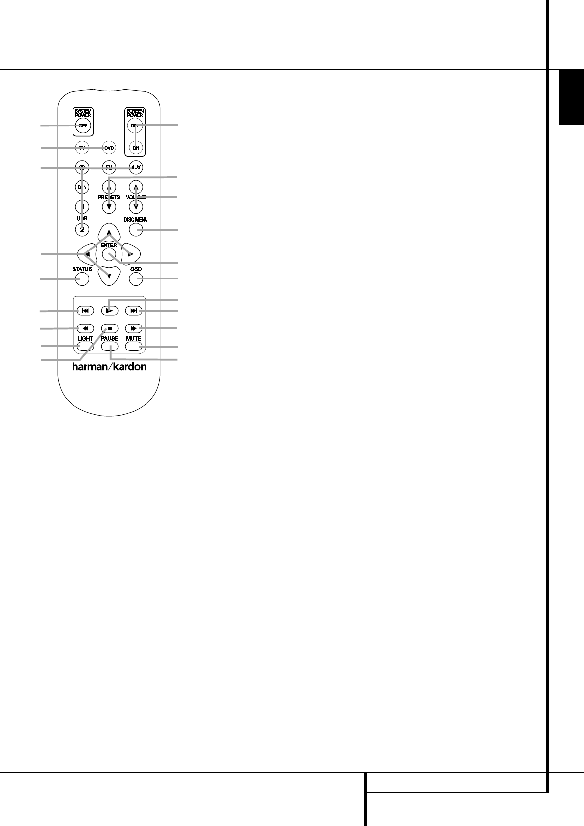
Remote Control
33
2
21
39
12
29
35
37
30
1
26
9
10
7
32
14
4 11
27
22
38
24
5
25
2331
336
13
18 20
15
19 17
28 34
8 6
16
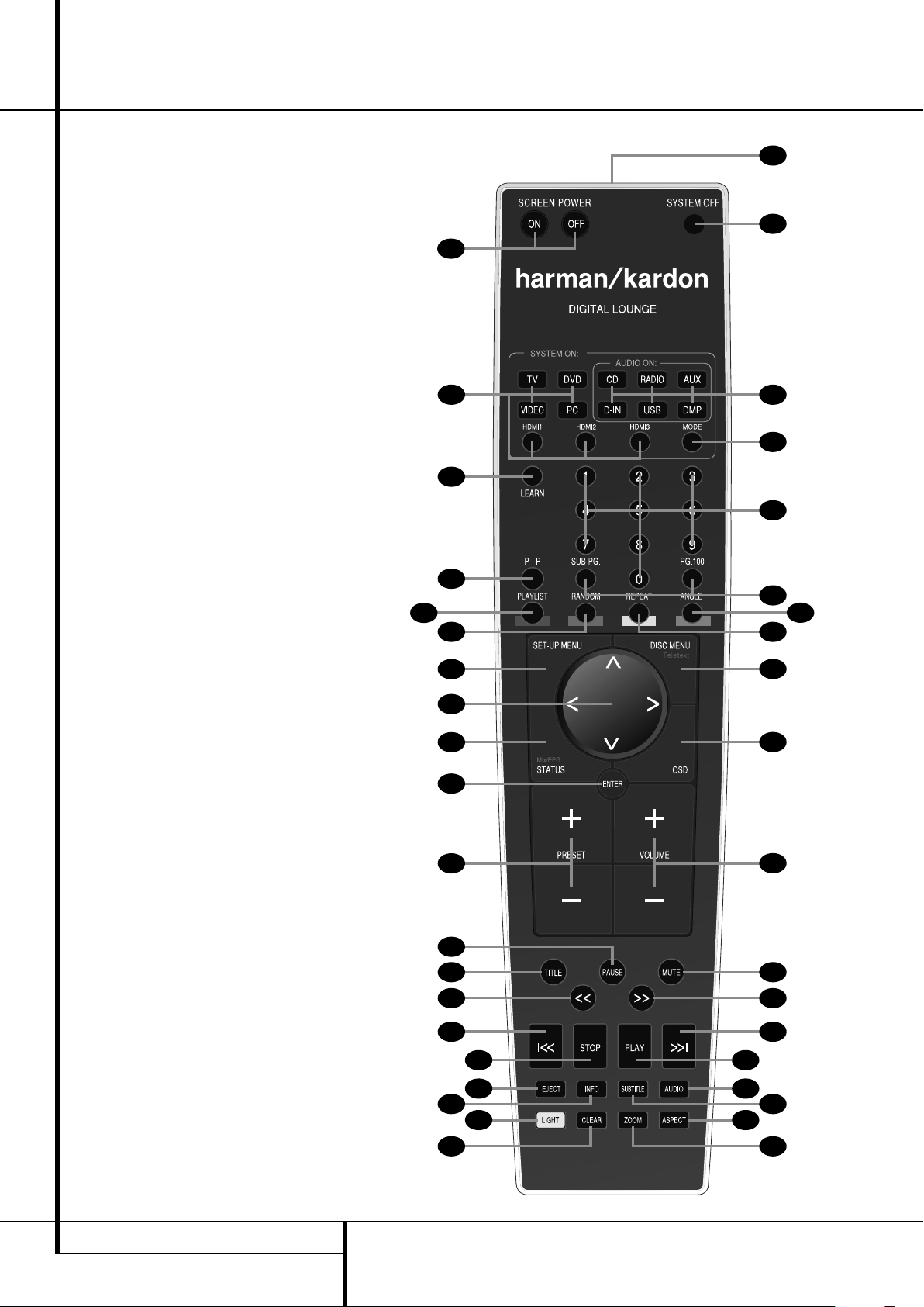
0
System On/Source Selection Button
1
Power Off Button
2
Subtitle Button
3
Title Button
4
Angle Button
5
Audio Button
6
Enter Button
7
Eject Button
8
Set-Up/Button
9
Arrows Button
A
Mute Button
B
Disc Menu/Teletext Button
C
Pause Button
D
Status/Mix/EPG Button
E
Skip/Step (Previous) Button
F
Skip/Step (Next) Button
G
Play Button
H
Search/Slow Reverse Button
I
STOP Button
J
Search/Slow Forward Button
K
Audio System On/Source Selection Button
L
Presets - Button
M
Zoom Button
N
Playlist Button
O
Random Button
P
Learn Button
Q
Volume up/down Button
Light Button
Numeric Key Buttons
Repeat Button
Clear Button
OSD Button
IR Transmitter Window
Aspect Button
Screen Power Buttons
Info Button
Teletext Buttons
Picture in Picture Button
Mode button
14 REMOTE CONTROL
Page 15

Remote Control
0
System/Source Selection Buttons:
Pressing one of these buttons will perform three
actions at the same time for those sources that
require the display to be switched on. First, if the
System is not turned on, this will power up the
system. Next, "DVD" will select the player as
source, the other buttons will select TV IN as
source on the receiver while the screen will
always turn to the last input selected. If the system is on already TV will select the TV tuner as
screen source, DVD the HDMI input, VIDEO will
toggle though all analog inputs of the screen
and PC will toggle through the RGB-DVI or the
digital DVI input. Finally pressing one of these
buttons will change the remote control so that it
controls the device selected (TV, VIDEO and PC
the screen, the others the receiver).
1
Power Off Button: Turns off the system to
standby mode.
2
Subtitle Button: When a DVD is playing,
press to select a subtitle language or to turn subtitles off.
3
Title Button: When a disc is playing, press
to make the player go back to the first section of
the disc.
4
Angle Button: Press to access various
camera angles on a DVD (If the DVD contains
multiple camera angles) or to rotate JPEG
images.
5
Audio Button: Press to access various
audio languages on a DVD (If the DVD contains
multiple audio streams).
6
Enter Button: Press this button to activate
a setting or option.
7
Eject Button: Press to release the disc
from the loader.
8
Set-up: This button has several functions.
0
In TV mode (press the TV Button
pressing the Set-up Button) it gives access to TV
Set-up menu, in which the picture calibration
settings of each individual input can be set. In
any other mode (press any of the other source
0
selection buttons
Button) it will access the Set-up menu of the
DVD receiver. Press to access the On Screen
Display Menu.
9
Arrow (M/N/K/L) Buttons: Use to
move the cursor in the OSD.
A
Mute Button: Mutes the sound.
B
Disc Menu/Teletext Button: Displays the
actual DVD Disc Menu on the TV screen in play
mode. When playing discs with JPEG images,
pressing this button will access the thumbnails.
In TV mode, pressing this button will activate the
Teletext function, pressing it a second time will
add the TV program in splitscreen form.
When only the Teletext is visible pressing the
STATUS/MIX/EPG button
Teletext and the TV program.
or Kprior to the Set-up
D
prior to
will mix the
C
Pause Button: Freezes a picture (with
DVD/VCD) and pauses the playback signal (CD)
when a disc is playing. Press again for normal
playback.
D
Status/Mix/EPG Button: Press while a
disc is playing to view banner display. Use the
ARROW buttons to move through the different features in the Banner Display. When a symbol is high lighted, press ENTER on the remote to select it.
In DVB-T TV mode pressing this button calls up
the Electronic Program Guide (EPG), which lists
future programming for the day or week,
(depending on the country in which you live and
the station). In analog TV mode pressing this
button blends the teletext information with the
TV picture.
E
Skip/Step (Previous) Button: Press to go
to beginning of current track. Press again quickly
to go to beginning of previous track. After pressing the PAUSE button, each press of this button
will move the image in reverse frame by frame.
F
Skip/Step (Next) Button: Press to go to
beginning of next track. After pressing the PAUSE
button, each press of this button will move the
image forwards frame by frame.
G
Play Button: Begins to play disc (closes
disc tray first, if it is open).
H
Search/Slow (Rev.) Button: Allows you
to search in reverse through a disc while it is in
play mode. Each time you press this button, the
search speed changes as indicated by a number
of arrows on the right top of your screen.
After pressing the PAU SE button, each press of
this button will change the slow down speed
indicated by a number of arrows in the right top
of the screen.
I
Stop Button: Stops playing a disc. When a
disc is playing, if you press STOP and PLAY, the
disc will resume play, i.e. it will start from the
same point on the disc where the unit was
stopped. If you press STOP twice and the PLAY
button, the disc will start play from the beginning.
J
Search/Slow (Fwd.) Button: Allows you
to search forward through a disc while it is in
play mode. Each time you press this button, the
search speed changes as indicated by a number
of arrows on the right top of your screen.
After pressing the PAU SE button, each press of
this button will change the slow down speed as
indicated by a number of arrows in the right top
of the screen.
K
Audio System On/Source Selection
Buttons: Pressing one of these buttons will per-
form three actions at the same time for sources
that do NOT necessarily require the screen to be
switched one. First, if the System is not turned on,
this will power up the system without the screen.
Next, it will select the source shown on the button as the input to the system. Finally, it will
change the remote control so that it controls the
device selected. With audio-only sources, the
screen can be temporarily switched on or off with
the Screen Power Buttons
L
Presets Buttons: Pressing these buttons in
JPEG mode will move to the previous or next
image.
In TV mode these buttons will scroll through the
available preset TV stations. With DivX movies
these buttons will jump forward or backward for
10 minutes.
M
Zoom Button: When a DVD or VCD is
playing, press this button to zoom the picture so
that it is enlarged. There are 4 steps to the zoom
function, each progressively larger. Press through
each of the zoom stages to return to a normal
picture. The Zoom function is not available when
watching High Definition material.
N
Playlist Button: Press this button to
change the playback order of the disc.
O
Random Button: Press for RANDOM
playback in random order.
P
Learn Button: Press this button to begin
the process of “learning” the codes from another
product’s remote into the Digital Lounge
System’s remote. (See page 44 for more information on using the remote’s learning function.)
Q
Volume Up/Down: Increase/
decrease the master volume level.
LIGHT Button: Press to illuminate remote
controller.
Numeric Key Buttons: Select numbers by
pressing these buttons.
Repeat Button: Press to go to the Repeat
menu. You can repeat a chapter, track or the
entire disc.
Clear Button: Press to remove the Banner
menu from the screen.
OSD Button: This button has several functions. In TV mode (press the TV Button
to pressing the Set-up Button) it gives access to
TV OSD menu, in which the video input selection
can be made. In any other mode (press any of
the other source selection buttons
prior to the Set-up Button) it will access the OSD
menu of the DVD receiver.
.
0
prior
0
or
K
ENGLISH
REMOTE CONTROL 15
Page 16

Remote Control
IR Transmitter Window: Point this window
towards the Digital Lounge system when pressing
buttons on the remote to make certain that
infrared commands are properly received.
Aspect Button: Press this button to scroll
through the available screen formats. The default
setting is Fill All.
Screen Power Buttons: Use these buttons
to temporarily switch on or off the screen when
listening to audio-only sources. This could be
helpful for instance for scrolling through the contents of MP3 discs or portable hard disk devices.
INFO: Press for detailed informations on the
disc playing (Video/Audio Bit rate, Movie aspect
ratio and others), and for current player settings
made. Press again to remove information from
screen.
Teletext Buttons: Press these buttons with
Teletext activated (by button
different Teletext functions. Pressing the 100Button will always call up the main Teletext page.
Pressing the Sub Page Button consecutively will
scroll through the available sub pages of a page.
Picture in Picture Button: Press this button
once to activate the Picture in Picture function.
Press it again to activate the picture out of picture
function (split screen).
Note: When Picture in Picture is activated the
main picture can be selected by the numeric
buttons
(when TV tuner is source) and the
secondary picture by the PRESET Buttons
while pressing the PC or VIDEO button will toggle
through all available PC and Video sources as
secondary picture.
Mode Button: This button enables you to
switch the remote to another mode so that it
operates another device without selecting it as
the source. Each press of the Mode button
changes the remote’s mode in this order: TV,
DVD, VIDEO, PC, HDMI 1, HDMI 2 and HDMI 3.
And then back to TV again. The corresponding
Source Selector will light to indicate the mode.
Important Note: When toggling through the
resolution modes by pressing this button
repeatedly be sure to have your screen connected
via HDMI or Component cable, otherwise you will
not see a picture with the progressive or the HD
modes. Note that via HDMI the Standard
interlaced signals (480/576i) will not appear.
B
) to select the
L
Important notes.
The large system remote control contains several
buttons that have more than one function. The
8
Set-up Button
both access the set-up menu of the TV and the
set-up menu of the DVD receiver. The final function of the button depends on the button pressed
prior to pressing the Set-up Button. Pressing the
TV, VIDEO or PC Source Selector Button
before the Set-up Button will access the TV
Set-up Menu. Pressing any of the other Source
Selector Buttons
Menu of the DVD receiver.
There are two ways to switch on the system. For
those sources that require the screen to be
switched on (TV, DVD, VIDEO or PC), pressing
one of the System On/Source Selector Buttons
0
will power on the complete system.
For those sources that do not necessarily require
the screen to be switched on (CD, RADIO, AUX,
D-IN, USB 1 and USB 2) pressing one of the
Audio System On/Source Selector Buttons
will power on the DVD receiver and the speakers,
but will leave the screen in stand by mode. In this
mode the screen can be switched on and off
temporarily by pressing the Screen Power On or
Off Buttons
For correct functioning of the remote control, it is
important NOT to switch on or off the DVD
receiver with the front panel Power On/Off
switch, but only to use the remote control's
System On
Buttons.
is a good example. It can
0K
.
0K
and System Off
0
will access the Set-up
K
1
16 REMOTE CONTROL
Page 17
Second Remote Control
A
B
C
D
E
F
G
H
Q
N
L
M
K
J
I
O
P
A
Power Off Button
B
System On/Source Selector Buttons
C
Audio System On/Source Selection Buttons
D
Arrow Buttons
E
Status Button
F
Skip/Step (Previous) Button
G
Search/Slow Reverse Button
H
Light Button
I
Screen Power Buttons
J
Presets Buttons
K
Volume Buttons
L
Disc Menu Button
M
Enter Button
N
OSD Button
O
Play Button
P
Skip/Step (Next) Button
Q
Stop Button
Search/Slow Forward Button
Mute Button
Pause Button
A
Power Off Button: Turns off the
DL system to standby mode.
B
System/Source Selection Buttons:
Pressing one of these buttons will perform three
actions at the same time for those sources that
require the display to be switched on. First, if the
System is not turned on, this will power up the
system. Next on the receiver, it will select the
source shown on the button as the input while
the screen will always turn on to the last source
selected. Finally, it will change the remote control
so that it controls the device selected.
C
Audio System On/Source Selection
Buttons: Pressing one of these buttons will per-
form three actions at the same time for sources
that NOT necessarily require the screen to be
switched one. First, if the System is not turned on,
this will power up the system without the screen.
Next, it will select the source shown on the button as the input to the system. Finally, it will
change the remote control so that it controls the
device selected. With audio-only sources, the
screen can be temporarily switched on or off with
I
the Screen Power Buttons
D
Arrow buttons (M/N/K/L) Buttons:
Use to move the cursor in the OSD.
E
Status Button: Press while a disc is playing to view banner display. Use the ARROW buttons to move through the different features in
the Banner Display. When a symbol is highlighted, press ENTER on the remote to select it.
F
Skip/Step (Previous) Button: Press to go
to beginning of current track. Press again quickly
to go to beginning of previous track. After pressing the PAUSE button, each press of this button
will move the image in reverse frame by frame.
G
Search/Slow Reverse Button: Allows you
to search in reverse through a disc while it is in
play mode. Each time you press this button, the
search speed changes as indicated by a number
of arrows on the right top of your screen.
After pressing the PAU SE button, each press of
this button will change the slow down speed
indicated by a number of arrows in the right top
of the screen.
H
LIGHT Button: Press to illuminate remote
controller.
I
Screen Power Buttons: Use these buttons
to temporarily switch on or off the screen when
listening to audio-only sources. This could be
helpful for instance for scrolling through the
contents of MP3 discs or portable hard disk
devices.
.
J
PRESETS-Buttons: Pressing these buttons
in JPEG mode will move to the previous or next
image. In TV mode these buttons will scroll
through the available preset TV stations. With
DivX movies these buttons will jump forward or
backward for 10 minutes.
K
Volume Buttons: Increase/decrease the
master volume level.
L
Disc Menu Button: Displays the actual
DVD Disc Menu on the TV screen in play mode.
When playing discs with JPEG images, pressing
this button will access the thumbnails.
M
Enter Button: Press this button to activate
a setting or option.
N
OSD Button: Press to access the On Screen
Display Menu.
O
Play Button: Begins to play disc (closes
disc tray first, if it is open).
P
Skip/Step (Next) Button: Press to go to
beginning of next track. After pressing the PAUSE
button, each press of this button will move the
image forwards frame by frame.
Q
Stop Button: Stops playing a disc. When a
disc is playing, if you press STOP and PLAY, the
disc will resume play, i.e. it will start from the
same point on the disc where the unit was
stopped. If you press STOP twice and the PLAY
button, the disc will start play from the beginning.
Search/Slow Forward Button: Allows
you to search forward through a disc while it is
in play mode. Each time you press this button,
the search speed changes as indicated by a number of arrows on the right top of your screen.
After pressing the PAU SE button, each press of
this button will change the slow down speed as
indicated by a number of arrows in the right top
of the screen.
Mute Button: Mutes the sound.
Pause Button: Freezes a picture (with
DVD/VCD) and pauses the playback signal (CD)
when a disc is playing. Press again for normal
playback.
ENGLISH
SECOND REMOTE CONTROL 17
Page 18

Basic Information
About This Manual
• The types of functions and operations that can
be used for a particular disc vary depending on
the features of that disc. In some cases, these
functions and operations may differ from the
descriptions given in this manual. In this event,
follow the instructions given on the screen. This
manual only covers basic disc operations.
• For some operations, the icon may appear
on the screen. This indicates that the operation
described in this manual is not available on the
disc in the player.
• On-screen and front panel display illustrations
in this manual are purely for the purposes of
explanation. The actual displays may differ
slightly from these illustrations.
Disc handling precautions
• To keep the disc clean, handle the disc by its
edge. Do not touch the surface.
• Do not stick paper or tape on the disc. If there
is glue (or a similar substance) on the disc,
remove the glue completely before using the
disc.
• Do not expose the disc to direct sunlight or
sources such as hot air ducts, or leave it in a
car parked in direct sun light as there can be a
considerable rise in temperature in side the car.
• After playing, store the disc in its case.
• Do not write on the label side with a ball-point
pen or other writing utensils.
• Be careful not to drop or bend the disc.
Disc cleaning precautions
• Before playing, clean the disc with a cleaning
cloth. Wipe the disc from the center out.
• Do not use solvents such as benzine, thinner,
commercially available cleaners or anti-static
spray in tend ed for vinyl LPs.
Disc installing precautions
• Do not install more than 1 disc on disc tray.
• Do not place the disc on the tray up-side down.
• Do not try to close the disc tray when the disc
is not installed and centered properly.
Regional Coding
DVD players and discs are designed with regional
restrictions which dictate the regions in which a
disc can be played. If the region number on the
disc you want to play does not match the region
number of your DVD player, you will not be able
to play the disc. The message “REGION ERR” will
appear in the front panel display.
The region code of this player is indicated on the
rear and on the external packaging.
Important basic principles for use
The LCD meets the highest quality requirements
and has been checked for pixel defects. Despite
taking the greatest care during production of
these units, for technological reasons it cannot be
excluded absolutely that there are some pixels
with defects.
We request your understanding for the fact that
such defects, provided that they are within the
limits specified by the standard, cannot be considered to be as an appliance defect in the terms
of the warranty.
If used for a long period of time as a PC screen,
shadows can occur on the screen as with any
other TV set. This phenomenon with LCD screens
can be reduced by heeding the following points:
• do not display a still picture for a long period of
time
• use your display in full screen format (16:9)
• activate the screen saver
• display moving images as far as possible
• always switch off the display when it is not
being used
• reduce the contrast and brightness as much as
possible.
Unfavourable conditions can cause your screen to
hum. The humming generally comes from the
mains voltage supply and can occur through the
connection of different earth conductors. You can
provide a remedy by putting a so-called sheath
current filter between the incoming aerial lead
and the aerial input socket on the display.
Sheath-type current filters are offered in the form
of a small adaptor plug in the retail trade.
If your display is connected to an external aerial,
the latter must be earthed as protection against
electric shocks and static charging. The earthing
must comply with the valid regulations.
If using it as a PC screen, we recommend for
ergonomic reasons that you avoid the use of red
and blue fonts or symbols against dark backgrounds.
To avoid aching eyes and obtain an optimized
viewing distance, the distance from the unit
should be five to six times the display’s diagonal
dimension. In your television room it should be so
light that you could also read. Too little light
strains the eyes due to the alternation between
light and dark on the display.
Cleaning the Screen
Before you start any cleaning, turn off the unit and
disconnect the mains plug from the plug outlet.
Cleaning the screen
The Harman Kardon Digital Lounge screens come
with a special cleening kit that allows for proper
cleaning without damaging the screen or its high
gloss finish. Use the mild detergent and soft cloth
only. Do not use any abrasives!
Cleaning the housing
The cleaning kit can also be used to clean the
housing of the screen.
Do not use any chemical solvents or cleaning
agents for cleaning the housing, otherwise the
surface of the unit could get damaged.
If you clean the surface of the housing with a wet
cloth, drops of water can get inside the unit,
which will cause malfunctions. Use a vacuum
cleaner with a soft brush attachment for cleaning
the ventilating openings.
18 BASIC INFORMATION
Page 19

Installation and Connections
RISKOFELECTRICSHOCK
DONOT OPEN
CAUTION
RISKOFELECTRICSHOCK
DONOT OPEN
CAUTION
RISKOFELECTRICSHOCK
DONOT OPEN
EXT. TRIGGER
INPUT
3-30 V AC
POWER ON
MODE
Important Note
Please open the Harman Kardon Digital Lounge
Accessory Tool Kit before opening any of the
other system components. The Kit contains two
pairs of gloves, that can be used to unpack the
LCD screen without damaging its frame nor
leaving fingerprints on it.
After unpacking the different system components,
and placing them on a solid surface capable of
supporting their weight, you will need to make the
connections to your audio and video equipment.
Equipment Connections
We recommend that you use the supplied cables
when making connections to source equipment
and high quality interconnect cables to additional
equipment to preserve the integrity of the
signals.
When making connections to audio source
equipment or speakers it is always a good
practice to unplug the units from the AC wall
outlet. This prevents any possibility of
accidentally sending audio or transient signals to
the speakers that may damage them.
Making the necessary connections to the Digital
Lounge system is done in five easy steps.
1. Connect the front, center and surround speaker
outputs
to the respective speakers.
Cables that are run inside walls should have the
appropriate markings to indicate listing with any
appropriate testing agency standards. Questions
about running cables inside walls should be
referred to your installer or a licensed electrician
who is familiar with the applicable local building
codes in your area.
When connecting wires to the speakers, be
certain to observe proper polarity. Note that the
positive (+) terminal of each speaker connection
now carries a specific color code. However, most
speakers will still use a red terminal for the
postive (+) connection. Con nect the “negative”
or “black” wire to the same terminal on both the
receiver and the speaker.
We also recommend that the length of cable
used to connect speaker pairs be identical.
For example, use the same length piece of
cable to connect the front-left and front-right
or surround-left and surround-right speakers,
even if the speakers are a different distance
from the Digital Lounge system controller.
2. Connections to the subwoofer are made via a
line level audio connection from the Subwoofer
Output
of the subwoofer. Connect at the same time the
Subwoofer Trigger Output
Input of the subwoofer.
to the line-level SUB input (purple)
to the Trigger
3. Connect the supplied FM antenna to the FM
(75 ohm) connection
. The FM antenna may
be an external roof antenna, an inside powered
or wire lead antenna or a connection from a
cable system. Note that if the antenna or connection uses 300-ohm twin-lead cable, you should
use a 300-ohm-to-75-ohm adapter to make the
connection.
4. Your system comes with an combined
HDMI/SP-DIF/Remote in/out cable to make a digital video connection over HDMI and digital
audio connection from the TV to the DVD re ceiver. Connect the HDMI connector on one end
of the wire to the HDMI Output
er and the other end to the HDMI Input
of the receiv-
J
of
the screen. Connect the Coaxial Digital connector
on one end of the cable to the Coaxial Digital
Input
Coaxial Digital Output
of the receiver and the other end to the
H
of the screen.
Connect one end of the remote connector (the
single pin connector) to the Remote Input of the
screen and the other end to the Remote Input of
the DVD Receiver. Please note that you may run
the remote signal both ways. If you decide that it
is easiest for you to control both screen and
receiver by pointing the remote control towards
the screen, plug the remote cable into the
Remote Control Out of the screen and into the
Remote Control In of the receiver. If your setup
makes it more practical to aim the remote at the
receiver to control both receiver and screen, plug
the remote cable into the Remote Control Out of
the receiver and into the Remote Control In of
the screen.
5. If you use a standard analog TV antenna, con-
D
nect to the Antenna Input
on the rear panel
of the screen. In case you use a DVB-T antenna,
Z
connect that one to the DVB-T Input
on the
rear panel of the screen.
All necessary connections are now made. If you
have additional source components to add,
please refer to the next paragraphs. If not, please
continue with the next chapter of the manual.
Optional Analog Set Top or Cable
Box Connections
If you do not use an aerial antenna but a set top
box or cable box to watch TV, please follow the
instructions below to connect these products.
SCART
If you decide to connect your set top or cable box
to your system using a Scart cable, connect the
Scart output of the set top or cable box to one of
F
the Scart Inputs
screen.
YUV/Component
If you decide to connect your set top or cable box
to your system using a YUV or Component cable,
connect the YUV outputs of the set top or cable
box to the YUV Inputs
the screen. At the same time connect the analog
audio outputs of the box to the Audio Input for
Component Video Jacks
the screen, or the digital output of the box to the
Coaxial Digital Input
S-Video
If you decide to connect your set top or cable box
to your system using an S-Video cable, connect
the S-Video output of the set top or cable box to
the S-Video Input
screen. At the same time connect the analog
audio outputs of the box to the Audio Input for
S-Video Jacks
or the digital output of the box to the Coaxial
Digital Input
Composite
If you decide to connect your set top or cable box
to your system using a Composite cable, connect
the Composite output of the set top or cable box
to the Composite/CVBS Input
panel of the screen. At the same time connect
the analog audio outputs of the box to the Audio
Input for Component Video Jacks
panel of the screen, or the digital output of the
box to the Coaxial Digital Input
Important Note: The Coaxial Digital Input
P
of the screen will accept only 2-channel PCM
signals (see item
multichannel sound from an optical digital output of any external source you can connect it to
the Optical Input
If your source has only a Coaxial Digital output
disconnect the SPDIF cable on the screen (out-
H
) and the unit (input), connect the
put
screen via the analog audio cable to the unit
(Audio Output
Input
on the unit). Then connect the coaxial
digital output of your source to the Coaxial
Digital Input
on the rear panel of the
E
on the rear panel of
O
on the rear panel of
P
.
M
on the rear panel of the
N
on the rear panel of the screen,
P
.
E
on the rear
O
P
.
P
on page 13). To listen to the
of the unit, see next page.
A
on screen to the TV Audio
of the unit.
on the rear
ENGLISH
INSTALLATION AND CONNECTIONS 19
Page 20

Installation and Connections
White
Red
Center Front�
Speaker
Optional Rear-Wall Mounting
TV or Projection Screen
Right Front�
Speaker
Left Front�
Speaker
No more than 2m�
when rear-mounted�
speakers are used
Connecting a PC
If you wish to connect your PC to the screen, the
best way is to connect the DVI output of the com-
K
puter to the DVI Input
on the rear panel of the
screen. At the same time connect the audio output
I
of your computer to the PC Audio Input
on the
rear panel of the screen. If your PC does not have a
DVI output, but VGA only, use an adapter cable
VGA->DVI to connect your PC to the DVI input of
the screen. If the grafic card of your PC has also
other video outputs, please use any of the available
outputs of your computer to the matching input of
the screen.
Connecting a Digital Set Top Box or
Satellite Receiver
If you wish to connect your digital set top box or
satellite receiver to the screen, the best way is to
connect the HDMI output of the satellite receiver to
RS
any of the HDMI 1 or HDMI 2
on the rear
panel of the screen. Both inputs are capable of
accepting up to 1080p signals.
Optional Audio Connections
Aux Input for External Source
You may connect a line-level stereo analog audio
source such as a Sat receiver, tape deck, phono preamp of a record player, etc. to the controller's rear
panel AUDIO IN Input
fits of your system with other source components.
• VCR Connection-Audio (Cables Not Included). To
listen to the sound from your stereo VCR through
the speakers of this system, connect the Left/Right
audio output jacks of your stereo VCR to the
Left/Right audio input jacks AUDIO IN
system.
Aux Output for Recording
To record the sound of the system with your VCR or
any audio recording device (tape deck, MD, CDR
and some others.) the Audio Out jacks
connected to the analog Record In jacks of the
appropriate device.
Digital In- and Outputs
Connect the optical digital output of any digital
sources such as an optional CD or DVD changer or
player, advanced video game, a digital satellite
receiver, HDTV tuner or digital cable set-top box or
the output of a compatible computer sound card to
the Optical Digital Inputs 1, 2 or 3
The Coaxial Digital ouput of those devices may be
connected with the Coaxial Digital input
the screen, (for PCM only) or the Coaxial Digital
Input
on the unit (for all formats), see page 19.
Connect the Coaxial Digital Output
rear panel of the Digital Lounge system to the
matching digital input connections on a CD-R or
MiniDisc recorder.
sockets to enjoy the bene-
PXW
of this
should be
P
on
on the
Note: When connecting the optical digital audio
cable (optional).
n Gently push the cable plug through the built-in
shutter that covers the optical digital audio output and connect the cable firmly so that the configurations of both the cable and the connector
match.
Speaker Placement
The placement of speakers in a multichannel
home-theater system can have a noticeable
impact on the quality of sound reproduced.
If you use the screen with the supplied table
stand, place the center loudspeaker in the designated place between the two feet of the stand.
Install the speaker from behind, and push it
gently forward until it can not go any further.
If you do not wish to use the supplied table
stand, place the center speaker either directly
above or below your TV. A wall bracket is supplied
for the Center Speaker for this purpose. Once the
center-channel speaker is installed, position the
left-front and right-front speakers so that they are
as far away from one another as the center-channel speaker is from the preferred listening position.
Ideally, the front-channel speakers should be
placed so that their tweeters are no more than
60cm above or below the tweeter in the centerchannel speaker. Depending on the specifics of
your room acoustics, you may find that imaging is
improved by moving the front-left and front-right
speakers slightly forward of the center-channel
speaker. If possible, adjust all front loudspeakers so
that they are aimed at ear height when you are
seated in the listening position.
Using these guidelines, you’ll find that it takes
some experimentation to find the correct location
for the front speakers in your particular installation. Don’t be afraid to move things around until
the system sounds correct. Optimize your speakers so that audio transitions across the front of
the room sound smooth.
The preferred location for surround speakers is on
the side walls of the room, at or slightly behind
the listening position.
Rear surround speakers may also be used in 5.1
channel mode as an alternative mounting position when it is not practical to place the main
surround speakers at the sides of the room.
Speakers may be placed on a rear wall, behind
the listening position. As with the side speakers,
.
the center of the rear surrounds should face you.
The speakers should be no more than 2 meters
behind the rear of the seating area.
The supplied pair of loudspeaker stands can be
used to either place the front- or rear loudspeakers. Follow the instructions in the manual of the
stands for proper installation of the loudspeakers
on the stands.
Subwoofers produce largely nondirectional
sound, so they may be placed almost anywhere in
a room. Actual placement should be based on
room size.
A) Front Channel Speaker Installation
with table stand
B) The distance between the left and right
speakers should be equal to the distance from
the seating position to the viewing screen.
You may also experiment with placing the left
and right speakers slightly forward of the center
speaker. Rear speaker mounting is an alternate
location for 5.1 systems.
One method of finding the optimal location for a
subwoofer is to begin by placing it in the front
of the room, about 15cm from a wall, or near
the front corner of the room. Another method is
to temporarily place the subwoofer in the spot
where you will normally sit, and then walk
around the room until you find a spot where the
subwoofer sounds best. Place the subwoofer in
that spot.
20 INSTALLATION AND CONNECTIONS
Page 21

Installation and Connections Playback Basics
Screen Placement
Note: Please use the supplied pair of gloves
found in the Tool Kit when placing the screen.
This will prevent the high gloss finish of the
screen to be scratched or damaged. The screen
comes delivered with an integrated stand, that
has a dedicated place for the system's center
loudspeaker. Place the screen and the stand on a
surface that is strong enough to support its
weight.
You can also opt for hanging the screen on the
wall. Note that the screen should be mounted on
vertical walls only that are capable of bearing
three times the weight of the screen (see page 50
for the weight of your screen). We recommend
you to do the mounting with two people. Before
installing the screen on the wall, make sure that
it is switched off and that the mains cable and
signal cables are unplugged. Protect the front of
the screen using the cloth bag and turn the
screen so that its front is pointing downwards
and place it carefully on a completely flat and
firm surface.
Loosen and remove the 8 screws (M4x5) in the
stand. Please keep the screws in a safe place in
case you would like to re-install the screen on the
stand in the future.
Look at the attached drilling template in the
accessory pack to determine the appropriate distance between the two holes in the wall for your
individual display size.
Fit two plugs and hooks capable of carrying three
times the weight of the screen in the wall and
position the screen so that the hooks can be
introduced into the openings provided for this
purpose on the rear side of the screen.
Connecting the AC Power
Notes
• The Power Requirement is: AC 230V, 50 Hz.
• Connecting to power other than the one listed
above may damage the system or cause abnormal operation.
• Before connecting the AC power cord of this
system to a wall outlet, connect the speakers
and other component cables to the system.
• Connect the AC power cord of the active
subwoofer.
• Connect the AC power cords of your TV and
any optional components to a wall outlet.
Once the speakers have been placed in the room
and connected, the remaining steps are to
program the system configuration memories.
First Turn On
You are now ready to power up the system to
begin final adjustments.
Q
1. Plug the Power Cable
receiver and TV into an un switched AC outlet.
Press the Power On Switch
position to switch on the TV to Standby mode.
Note that the Power Indicator
Power Indicator on the screen will turn orange,
indicating that system unit is in the Standby
mode. At the same time, plug the power cord of
the subwoofer into an unswitched AC outlet.
2. Remove the protective plastic film from the
main front-panel lens of the DVD receiver.
If left in place, the film may affect the performance of your remote control.
3. Install the four supplied AAA batteries in the
main remote as shown. Be certain to follow
the (+) and (–) polarity indicators that are on
the top of the battery compartment. Follow the
same instructions to install the three supplied
AAA batteries into the smaller second remote
control.
of the DVD
G
to the "I"
1
and the
Automatic Channel Search
The first step after switching on your system is to
set the language you prefer and the country you
reside in. Once that is done, the automatic TV
channel search will start.
Setting the language
Figure 1a
• The first screen you will see is the Language
Selection screen. Use the [
9
to select the language you prefer to see
the menu's of the TV in. Press the Enter Button
6
to confirm.
Selection of country for the sorting
sequence
Figure 1b
• Once you have selected the menu language,
the next screen allows you to select the country
in which the TV will be operated. Use the [
K
] Buttons 9to select your country.
or [
Selection of tuner type
You will now be asked to choose between analog
or digital tuner.
L
] or [K] Buttons
L
ENGLISH
]
4. Turn the system on by pressing the TV Input
0
Source Selector
The Power Indicator
Indicator of the screen will turn blue to confirm
that the system is on, and the Main
Information Display
on the remote control.
1
and the Power
will also light up.
Figure 1c
Depending on your choice of tuner type, select
either "Analog" or "Digital (DVB-T)" by using
L/K
the
6
If you select the analog tuner, proceed as
described immediately below. If you select the
digital tuner, go to the DIGITAL TUNER (DVB-T)
section further down.
Buttons 9. Press the Enter Button
to confirm.
INSTALLATION AND CONNECTIONS 21
Page 22

Playback Basics
For analog tuner: proceed as follows:
When you press the Enter Button
6
to confirm,
the automatic channel search will start to scan
the available TV channels. The automatic search
can take several minutes, depending on the number of channels that are available.
Figure 1d
• Should you wish to abort the automatic
channel search, please press the Red Button
N
on your remote control.
If no TV channel is found, check the aerial connections and attempt to search for the channels
again.
When the automatic search is finished, the Edit
Channel List Menu will show on your screen. It
will show all the TV channels found indicated by
a name consisting a maximum of 5 characters.
This menu allows you to sort the TV channels
according to your preferences. Move the blue bar
L
by pressing the
Button until the TV channel
you would like to move is highlighted by the blue
6
bar. Press the Enter Button
so that the bar
turns white. You can now move it up, down, left
or right with the
K/L/M/N
Buttons 9until it
is at the requested preset. Press the Enter Button
6
to confirm. The white bar will turn blue to
confirm. Continue with all the other channels
until each preset contains your preferred TV channel.
The menu also allows you to delete TV channels
from your channel list. Move the blue bar to the
TV channel to be deleted using the
K/L
Buttons 9. Press the Green Button Oto
delete the TV channel.
When you are done making changes to the
N
Channel List, press the Red Button
to
remove the list from the screen.
Digital Tuner
If you have selected the digital tuner (DVB-T),
proceed as described below.
Figure 1e
You will now be asked whether you use an
actively powered antenna. Select either "On" or
"Off" by using the
The following automatic search screen will show:
Figure 1f
Press "Enter" to start the scanning process.
Scanning may take several minutes, and you will
see a status screen keeping you updated as to
how many percent of the scanning has been performed. You can interrupt the scanning at any
time by pressing the OSD button
scanning is complete, you will be asked to save
the new channels, and you are informed how
many channels were found.
K/L
Buttons 9.
. When
(If no channels are found, check the antenna connection. If you have used and indoor antenna, it
may be necessary to use an outdoor antenna
instead. It may be a good idea to check with your
TV network provider if there is DVB-T coverage in
your area at all. If not, use analog tuner or
cable/satellite reception instead). Press "Enter"
to confirm the line "Yes, add new channels". If
you want to completely replace an earlier version
N
channel list, press the
button to select "Yes,
replace old channel list" and confirm with the
"Enter" Button. If you do not want to save any
N
new channels, press the
Button to select "No,
discard new channels" and confirm with the
"Enter" Button. After confirming, the following
screen will show:
Figure 1g
Press the Setup Button button 8to close the
Search for Channels menu and start watching TV.
Remember that once inside the menu system, you
simply press the "OSD"(On Screen Display) button to return to the previous screen and the
"Setup Menu" button to exit the menu system
entirely.
If you want to change additional settings in the
DVB-T menu, like sorting channels, watch technical information or set security settings, press the
OSD Button
lowed by the
once to go back one level, fol-
K/L
Button 9to select the
menu you want (when coming directly from the
Channel Search function).
If you want to change settings for the DVB-T
tuner when watching TV, press the "Set-Up
8
Menu" button
the TV heading showing black, press the
9
twice to move the indicator bar down to
ton
the DVB-T Setup line and press "Enter"
to enter the Setup Menu with
L
but-
6
. The
screen changes to System settings, with the blue
dot at the left side indicating which menu point
you have chosen. The top menu line states the
name of the menu item in the following order,
downwards: System Settings, Search for
Channels, Sort Channels, Technical Information
and Security. You select the menu you want by
K/L
scrolling down and up with the
9
. Notice that the bottom menu line offers fur-
Buttons
ther explanation for the menu you have selected.
6
Press "Enter"
inside each main menu, and press "OSD"
to enter the detailed menu
to
return to the previous menu. Once inside a
detailed menu, you may alter various settings.
22 PLAYBACK BASICS
Page 23

Playback Basics
If you select Sort Channels, you will see the menu
below:
Figure 1h
Press the Enter button to enter the Sort TV channels menu and the overview of the channels in
the memory.
Figure 1i
The Sort TV channels menu permits you to rearrange the channels, sorting them in numerical
order or alphabetically from A - Z or Z - A, even
according to Network or Provider if you wish.
Also, you may select channels to be your
Favourites and move them to a separate
Favourites list, which you can use for everyday
viewing. You are also informed which channels
are scrambled and therefore cannot be watched.
To delete channels, select a channel with the
Button 9. Delete with the Red button N.
To filter channels, press the Yellow button
The Filter Channels screen will show. You may
select Free to air, Scrambled or All channels for filtering, as well as the order of filtering.
You can move channels from the Channels list to
the Favourites list by pressing the "Enter" button
6
after having selected the station you want to
move with the
between Channels and Favourites with the Blue
button
the Favourites list, simply switch to this list with
the Blue button, find the station with the
Buttons and press the Red button Nto delete.
When watching TV, you can switch between the
total channel list and your selected favorite list by
pressing the Blue Button. Each press toggles from
one list to the other and back, to make it easy for
you to have all available channels or just the
ones you prefer present for selection.
You may also choose to do a manual search if
you know the frequency for a channel that you
want to see.
K/L
Buttons 9. Switch
4
. If you want to move a station out of
K/L
K/L
.
Figure 1j
In the Technical Information menu you can see
details regarding the channel that you are currently watching, or the DVB-T tuner. You may
update the DVB-T software via the antenna by
pressing Enter to confirm the Update Software
prompt. This may take several minutes, and if no
new software is available, you will be informed
about this.
Figure 1k
The Security menu gives you the option to lock
the DVB-T tuner in order to avoid children watching programs unsuited for their age. When pressing "Enter", the screen asks for a four-digit PIN
code. The default code is "0000". Enter the code
and press "Enter". You will see the menu lines
"Parental Control" and "Change Pin". The
Parental Control permits ages from 4 to 18 years
to be selected, or "Off". At the time of writing,
this age-based system is not in use, but plans are
progressing to introduce age codes to be transmitted along with the program content, to
exclude programs that are marked to be for children older than the set limit.
You may also change the PIN code. You will be
asked to give the present code once, the new
code once and then once more to confirm.
Remember the new code.
Figure 1l
The topmost menu is "System Settings", which
permits you to customize the DVB-T tuner settings that you do not need to alter very often.
Entering "System Settings" shows the following
screen with three setting options: Language,
Menu and Miscellaneous.
Figure 1m
Language Settings lets you select your first
and second choices of Audio language, your first
and second choices of subtitle languages and
whether or not you want subtitles at all. Please
note that these options are available only if the
channel you watch transmits them.
Menu Settings lets you decide how long the
Information Banners should be visible on the
screen. You may select from 1 second to 15 seconds as well as Permanent and None. If you
select 4 seconds or more, you may also select the
Info Banner Automatic to be On or Off. This
option shows an information bar when a new
programme starts if selected On.
Miscellaneous Settings lets you choose
between manual or automatic time zone adjustment. If manual is chosen, you may enter the
time zone of your choice. If automatic is chosen,
the tuner receives time information from the
DVB-T system, including info about
Summertime/Daylight Savings Time. You may also
select active antenna or not, if you change the
antenna to another type. Do not select Active if
you are not absolutely sure that you do have an
active antenna. You may switch the channel list
appearance to list the channels alphabetically A-Z
or Z-A, or according to provider, or to show no
sorting at all.
Basic Play
Preparation
1. Depending on what source you would like to
watch or listen to, there are two ways to
switch on the system. In order to switch on the
whole system, including the screen, to watch a
source, press any of System On/Source
0
Selectors
on the DVD receiver, for instance to simply listen to a CD, press any of the Audio System
On/Source Selector Buttons
2. When you switch on the complete system, a
Harman Kardon Digital Lounge welcome
image should appear on the screen.
3. If there is no picture at all, not even the
Harman Kardon screen, please check whether
the HDMI cable has been inserted correctly.
This cable needs always to be connected
before switching on the screen and the receiver.
. If you would only like to switch
K
.
ENGLISH
PLAYBACK BASICS 23
Page 24

Playback Basics
TV
4. If the TV Source Selector Input Button 0has
been pressed to switch on the complete
system, the system and the remote control are
in TV mode.
5. Press the Preset Up or Preset Down Buttons
LJ
to scroll through the available chan-
nel presets.
6. Press the Volume Up or Volume Down Buttons
QK
to increase or decrease the system's
volume level.
DVD Receiver
If any of the DVD 0or Audio Source Selector
K
Buttons
system (with or without screen), the system and
the remote control are in receiver mode.
7. Insert a disc into the Slot Loader
Hold the disc without touching either of its
surfaces, position it with the side you wish to
play facing down, align it with the guides, and
place it in its proper position.
• 3" (8 cm) discs or 5" (12 cm) discs can be used.
8. After the discs slides into the loader, it will
start playing automatically.
have been pressed to switch on the
6
.
Disc Playback Features
Skipping tracks or titles/chapters
To move forward or backward through the tracks
on a CD or the titles or chapters on a DVD, press
EF
Previous/Next
Fast Motion Playback/Fast Search
1. To move forward or backward through the
DVD or CD disc being played at fast speed,
press Search
of these buttons is pressed, the fast search will
continue until Play is pressed.
There are four fast-play speeds. Each press of the
Search Buttons will cycle to the next speed in the
following order: 2x, 4x, 16x, 100x, indicated by a
number of arrow indicators on the right top of
the screen.
2. Press PLAY
playback.
Note that there will be no audio playback during
fast-forward or -reverse play of DVD discs. This is
normal for DVD, as surround processors cannot
process the digital audio streams during fast-play
modes; audio will be heard during fast-play of
conventional CD’s.
Freeze Frame and Frame Advance
(with DVD only)
1. Press PAUSE
freeze the picture.
2. Each time you press one of the STEP (FWD or
EF
REV
one frame in the selected direction.
3. Press PLAY
.
HJ
on the remote. Once one
G
at any time to resume normal
C
when a DVD is playing to
) buttons, the picture advances
G
to resume normal playback.
Slow Motion Playback (with DVD only)
1. When a DVD disc is in pause or freeze frame
mode, you may move slowly forward or backward through the program being played at one
of four speeds by pressing the SEARCH
HJ
Buttons
the buttons will move to the next speed, indicated by a number of arrow indicators on the
right top of the screen.
2. Press PLAY
Note that there will be no audio playback during
slow-forward or -reverse play of DVD discs. This is
normal for DVD, as surround processors cannot
process the digital audio streams during slow
modes. Slow play is not available for CD.
Notes: Playback features may not be available
during the opening credits of a movie. This is
intended by the disc author and is not a failure of
the Digital Lounge system Controller.
Playback of a DVD with 96 kHz/24-bit audio
requires the use of circuitry normally used for
other features. Accordingly, Slow Play Reverse
and Step Advance features are not available with
these discs.
Depending on the structure of a VCD disc, the
functions Slow Reverse and Step Reverse may be
prohibited or have no function and Fast Playback
(Search) may not function.
About DivX Movie Files
The DivX disc compatibility of this DVD player is
limited by the following:
• the available resolution size of the DivX file
should be maximum 720x576 (W x H) pixels.
• the total number of files and folders on the disc
should be less than 999.
• the number of screen frames per second should
be maximum 29.97 frames per second.
• the video and audio structure of recorded file
should be interleaved.
The player is capable of playing DivX files with
the extensions “.avi”.
The player is capable of playing subtitle files with
the extensions “.smi”, “.srt”, “.sub (Micro DVD
format only)” or "ssa". Other subtitle files won’t
be displayed. Subtitle files need to carry the same
name as the movie file (but with either one of the
above extensions) and should be located in the
same directory.
on the remote. Each press of
G
to resume normal playback.
Playing a DivX Movie Disc
Before playing DivX movie discs, please note the
following:
• multi session DVD containing Windows Media
Audio files may not be supported.
• open session discs are not supported.
• the DVD player does not support PC data.
• this DVD player does not support an unfinalized disc with a closed session.
6
1. Insert a disc into the Slot Loader
Hold the disc without touching either of its
surfaces, position it with the side you wish to
play facing down, align it with the guides, and
place it in its proper position.
2. In the On Screen Display opening select a fold-
er by pressing the up/down cursor buttons and
press ENTER. A list of files in the folder
appears. If you are in a file list and want to
return to the Folder list, use the up/down buttons on the remote to highlight the return icon
on top of the list and press ENTER.
3. If you want to view a particular file, press the
up/down buttons to highlight a file and press
ENTER (PLAY will always play the first file on
the disc).
When playing back a DivX movie you can use
variable playback functions like fast backward
and forward, as well as step and slow forward
while slow and step backward are not possible.
To facilitate the navigation with DivX/XviD
movies you can jump forward/backward for 10
minutes by pressing the Preset +/- buttons
on the remote.
4. Press STOP to stop the playback.
The DVD player’s playback functionalities of DivX
video discs will vary depending on the DivX
version used for creating your movies.
.
L
24 PLAYBACK BASICS
Page 25

Playback Basics System Setup
(B)
(A)
(E) (D)
Surround Mode
One of the most important features of the
Digital Lounge system is its ability to reproduce a
full multichannel surround sound field from digital sources, analog matrix surround encoded programs and standard stereo programs.
Selection of a surround mode is based on personal taste, as well as the type of program source
material being used. For example, motion pictures, CD’s or TV programs bearing the logo of
one of the major surround encoding processes,
such as Dolby Surround should be played in
either the Harman proprietary Logic 7 Movie or
Dolby Pro Logic II Movie (with movies) or Logic 7
Music or Dolby Pro Logic II Music (with music)
surround mode.
Surround modes and audio formats are selected
using the remote. Press the AUDIO button
toggle between the surround modes/audio formats available on the DVD disc. As you press the
button, the Surround mode/ audio format name
will appear on your video display.
When a digital source is present, the DVD receiver will automatically select and switch to the correct mode (Dolby Digital or DTS), regardless of
the mode that has been previously selected.
To listen to a DVD-program in traditional two
channel stereo, using the front left and front
right speakers only plus the subwoofer, follow
the instructions shown in the chapter DVD Sound
Mode, in the Audio Settings Menu.
5
System Defaults
The final step of the installation is to establish
the system’s defaults. It is helpful to take a few
minutes to famili arize yourself with these settings, as they may require change before the first
use and later from time to time.
General Functionality of the
User Interface
The complete setup and control of the Digital
Lounge takes place in an advanced Guided User
Interface menu system. The Guided User Interface
integrates four individual menu structures, all
easily accessible via the remote control:
• Set Up Menu for the Screen
• Set Up Menu for the DVD receiver
• On Screen Display Menu for the Screen
to
• On Screen Display Menu for the DVD receiver
All menus are easily accessible via the remote
control.
The main menu of the DVD-Receiver is available
by pressing the OSD Button
being in receiver mode (see page 24). It consists
of a DISC Menu, RADIO Menu, TV Menu, AUX
Menu, DIGITAL Menu, USB Menu, DMP menu
and a SET-UP Menu. The DISC Menu will show all
infor mation and options available for the disc
currently playing. The RADIO Menu will show
radio and RDS options. The TV, AUX and DIGITAL
Menus show the surround options for these specific audio inputs. The USB Menu will show all
information and options available when USB
thumb devices or portable hard disks are connected. The DMP menu helps you browse
through your music library once your iPod is connected to your Bridge.The SET-UP Menu will help
you configure all audio and video settings which
are normally only made once.
As the connection between the screen and the
DVD receiver is over HDMI, you will be able to
benefit from having high resolution interface
images, that are text based.
Many menus contain Submenus or text lines.
These submenus are shown on the left side of
the menu. They can be highlighted by a white
square around the text by moving the cursor with
9
the ARROW
by pressing ENTER
ed. When ENTER
color of the circle behind the text will change to
light blue, and you will see that the current settings of this submenu will appear on the right
side of the menu. Although some Menus have
various Submenus and Settings, they are all navigated in the same way. All sub menus, settings
and options can be accessed with the help of the
ARROW (
on the remote control.
buttons. Text can be activated
6
6
KLNM
9
when they are highlight-
has been pressed, the
) and ENTER 6buttons
on the remote,
To change a setting, simply move the cursor to
the setting you wish to change. This setting will
be high lighted in a white square, and a brief
expla na tion will appear in the Upper Menu Line
on the bottom of your screen, together with the
available options for this setting on the Lower
Menu Line.
Once the setting is highlighted, pressing ENTER
will show an
setting to indicate that the setting can be
changed by pressing the left or right ARROW
Button
the requested setting is shown, and confirm this
setting by pressing ENTER
you cycle though the options for this setting, the
cursor cycles though the options on the Lower
Menu Line, and the rest of the Display fades out.
M
and Nicon next to the current
9
. Press the ARROW Buttons 9until
6
. Note that when
Figure 2a
(A) Main Menu Line
(B) Submenus
(D) Upper Menu Line with Brief Explanation
(E) Lower Menu Line with Possible Options
(not shown in the menu here)
Set Up Menu for Screen
If the Screen Set Up Menu is not already on the
0
screen, press the TV Button
8
Set-Up Button
to call it on the screen.
Figure 2b
The Screen Setup Menu handles picture calibration and set up of each individual input connected to the screen. All possible video inputs are
listed on the top of the menu, and can be selected by moving from one tab to the next one using
NM
Buttons 9on the remote control. The
the
selected input is highlighted by a dark blue lit
tab, all other tabs will be shown in light blue.
followed by the
ENGLISH
-
SYSTEM SETUP 25
Page 26

System Setup
TV Set Up
The TV Set Up Menu contains 2 submenus. Each
submenu can be selected by moving the blue bar
KL
with the
submenu is highlighted and pressing the Enter
Button
will be marked by a light blue circle behind the
submenu text line.
Figure 2c
Picture Calibration
The first submenu is the Picture Calibration
Submenu that allows you to calibrate the picture
of your TV. With the TV Set Up Menu on the
screen, press the
Calibration text line is highlighted. Press Enter
6
to select, followed by pressing the NButton
9
to access the different calibration settings.
Contrast: The optimal contrast setting will
depend of your preference and the surrounding
light in the TV room. Should you wish to change
this setting, press the Enter Button
highlighted. The TV Set Up Menu will be replaced
temporarily by a Mini Bar on the right top of the
screen, allowing you to verify the changes made
to the contrast setting in real time. To change the
setting press any of the
the right contrast setting has been reached. Press
the Enter Button
process or the Red Button
TV channel.
Figure 2d
Brightness: The next line in the picture calibration process is the Brightness Setting. Should you
wish to change this setting, press the Enter
Button
Menu will be replaced temporarily by a Mini Bar
on the right top of the screen, allowing you to
verify the changes made to the brightness setting
in real time. To change the setting press any of
N
the
setting has been reached. Press the Enter Button
6
to return to the calibration process or the
Red Button
Buttons 9until the requested
6
to confirm. The selected submenu
L
Button 9until the Picture
6
once it is
N
or MButtons 9until
6
to return to the calibration
N
to return to your
6
once it is highlighted. The TV Set Up
or MButtons 9until the right brightness
N
to return to your TV channel.
Sharpness: The next line in the picture calibration process is the Sharpness Setting. Should you
wish to change this setting, press the Enter
6
Button
once it is highlighted. The TV Set Up
Menu will be replaced temporarily by a Mini Bar
on the right top of the screen, allowing you to
verify the changes made to the sharpness setting
in real time. To change the setting press any of
N
or MButtons 9until the right sharpness
the
setting has been reached. Press the Enter Button
6
to return to the calibration process or the
N
Red Button
to return to your TV channel.
Color: The next line in the picture calibration
process is the Color Setting, in which the color
saturation can be adjusted. Should you wish to
change this setting, press the Enter Button
6
once it is highlighted. The TV Set Up Menu will
be replaced temporarily by a Mini Bar on the
right top of the screen, allowing you to verify the
changes made to the color setting in real time. To
N
M
change the setting press any of the
or
Buttons 9until the right color setting has
6
been reached. Press the Enter Button
to
return to the calibration process or the Red
N
Button
to return to your TV channel.
Color Balance: The next line in the picture calibration process is the Color Balance Setting,
allowing to adjust the color temperature. Should
you wish to change this setting, press the Enter
6
Button
once it is highlighted. The TV Set Up
Menu will be replaced temporarily by a Mini Bar
on the right top of the screen, allowing you to
verify the changes made to the color
balance setting in real time. To change the
N
setting press any of the
or MButtons 9until
the right color balance setting has been reached.
6
Press the Enter Button
calibration process or the Red Button
to return to the
N
to
return to your TV channel.
Picture Emission: The next line in the picture
calibration process is the Picture Emission
Setting. This setting adjusts the intensity of the
light of the display. Brightly lit rooms will get best
video performance with a Picture Emission set to
"Light". In dark rooms, the "Dark" setting
should be chosen. Should you wish to change
6
this setting, press the Enter Button
once it is
highlighted. The TV Set Up Menu will be replaced
temporarily by a Mini Bar on the right top of the
screen, allowing you to verify the changes made
to the picture emission setting in real time. To
N
M
change the setting press any of the
or
Buttons 9until the right picture emission setting has been reached. Press the Enter Button
6
to return to the calibration process or the
N
Red Button
to return to your TV channel.
Dynamic Noise Compensation: The next line
in the picture calibration process is the Dynamic
Noise Compensation Setting. With this setting
you can compensate for possible noise that is
detected in any analog video signal. Should you
wish to change this setting, press the Enter
6
Button
once it is highlighted. The TV Set Up
Menu will be replaced temporarily by a Mini Bar
on the right top of the screen, allowing you to
verify the changes made to the dynamic noise
compen sation setting in real time. To change the
N
setting press any of the
or MButtons 9until
the right dynamic noise compensation setting
6
has been reached. Press the Enter Button
to
return to the calibration process or the Red
N
Button
to return to your TV channel.
Aspect Ratio: The next line in the picture
calibration process is the Aspect Ratio Setting,
defining in what format you watch a specific
video input. Should you wish to change this set-
6
ting, press the Enter Button
once it is highlighted. The TV Set Up Menu will be replaced
temporarily by a Mini Bar on the right top of the
screen, allowing you to verify the changes made
to the aspect ratio setting in real time. To change
the setting press any of the
or MButtons
9
N
until the right settings has been reached. Press
6
the Enter Button
process or the Red Button
to return to the calibration
N
to return to your
TV channel. The aspect ratio can also be changed
directly (and individually for each input) by
pressing the Screen Format Button
The second line in this menu depends on your
choice of TV tuner. If you have selected a DVB tuner,
the DVB-T Setup line will appear, allowing you to
access the DVB T system Settings Menu, as
described on page 22-23.
If you use the analog TV tuner, the Automatic Search
and Manual Search menu lines will appear.
.
Figure 2e
26 SYSTEM SETUP
Page 27

System Setup
Automatic Search (For analog TV only)
The Automatic Search Menu allows you to automatically search for available TV channels. With
the TV Set Up Menu on the screen, press the
L
Button 9until the Automatic Search text line
6
is highlighted. Press Enter
N
by pressing the
Button 9to access the dif-
to select, followed
ferent automatic search settings. The TV’s tuner
has a memory for 99 TV stations.
Figure 2f
Country: The country line lets you select the
country you reside in to do a country-specific
sorting sequence of the TV channels. Should you
wish to change this setting, press the Enter
6
Button
once it is highlighted.
The blue bar will disappear and the rest of the
settings will fade out. Select the country you
reside in by pressing the
or MButtons
9
N
until the requested country is shown. Press the
6
Enter Button
to confirm.
Search Form: Selects whether you would like to
search for All Stations or New Stations. Should
you wish to change this setting, press the Enter
6
Button
once it is highlighted. The blue bar
will disappear and the rest of the settings will
fade out. Select the search form by pressing the
N
or MButtons 9. Press the Enter Button
6
to confirm.
Start Search: Starts the search for all or new TV
stations, depending on the setting made in the
previous line. To start the search, press the Enter
6
Button
once it is highlighted. The automatic
search menu will be replaced by the Auto Search
Progress Menu during the time of the search.
When the search is finished the Edit Channel List
Menu will appear on the screen. Follow the
instructions on page 28 should you wish to make
changes to the order of the presets or would like
to delete presets from the list.
Manual Search (For analog TV only)
The third submenu in the TV Set Up Menu is the
Manual Search Menu that allows you to manually search for available TV channels. With the TV
Set Up Menu on the screen, press the
9
until the Manual Search text line is high-
6
lighted. Press Enter
N
pressing the
Button 9to access the differ-
to select, followed by
ent manual search settings.
Figure 2g
Pre-set Station: Selects a new preset station
number. Should you wish to change this position,
6
press the Enter Button
once the line is highlighted. The blue bar will disappear and the rest
of the settings will fade out. Select the requested
N
position by pressing the
or MButtons
until it is shown. Press the Enter Button 6to
confirm.
Type: Selects whether you would like to search
for Channels or S-Channels (Special Channels,
Cable channels). Should you wish to change the
channel type, press the Enter Button
is highlighted. The blue bar will disappear and
the rest of the settings will fade out. Select the
requested type from the list by pressing the
M
Buttons 9. Press the Enter Button 6to
confirm.
The next steps depend on which information
about the TV station to add you have on hand.
Depending on whether you have the correct
channel number or the correct frequency, follow
one of the two steps described below.
Channel: Assigns the TV station’s channel number. If you know the correct channel number of
the TV station to add, press the Enter Button
once the line is highlighted. The blue bar will disappear and the rest of the settings will fade out.
Select the correct station number by pressing the
N
or MButtons 9from the list or by typing it
with the Numeric Keys
trol. Press the Enter Button
on the remote con-
6
to confirm. Note
that once confirmed, the frequency matching this
channel will automatically be shown.
Frequency: Assigns the TV station’s frequency. If
you know the correct frequency of the TV channel to add, press the Enter Button
line is highlighted. The blue bar will disappear
and the rest of the settings will fade out. Type
the station’s frequency with the help of the
Numeric Keys
the Enter Button
on the remote control. Press
6
to confirm. Note that once
confirmed, the channel number matching this
frequency will automatically be shown.
6
L
6
once the
Button
9
once it
N
Name: The line shows the input for the TV
station’s name and can contain up to five
characters. To enter the name, press the Enter
6
Button
once the line is highlighted. The blue
bar will disappear and the rest of the settings
K
will fade out. Press the
or LButtons 9to
scroll through the available characters to form
the stations name. When the first position contains the right character, move the cursor to the
N
right by pressing the
Button 9and select
the next character. Repeat this until all characters
are filled or until the correct name shows on the
line. Press the Enter Button
6
TV Standard: Selects the TV standard. Should
you wish to change the TV standard, press the
6
Enter Button
once it is highlighted. The blue
bar will disappear and the rest of the settings
will fade out. Select the requested TV standard
6
N
to confirm.
from the list by pressing the
Press the Enter Button
Note: If you do not know which TV standard to
choose, we recommend that you run the automatic channel search procedure.
Color Standard: Selects the Color standard.
Should you wish to change the color standard,
6
press the Enter Button
once it is highlighted.
The blue bar will disappear and the rest of the
settings will fade out. Select the requested TV
standard from the list by pressing the
Buttons 9. Press the Enter Button 6to
confirm.
Note: If you do not know which color standard
to choose, we recommend that you run the auto-
or
matic channel search procedure.
Decoder: Older Pay TV systems that require an
external decoder can be connected to either one
of the 2 Scart inputs. Depending on the decoder
type, change the Decoder Settings according to
the table below.
Decoder
TV channel
Sound Picture
Normal Uncoded Uncoded
6
Decoder A SCART1 Uncoded Coded
Decoder B SCART1 Coded Coded
Decoder A SCART2 Uncoded Coded
Decoder B SCART2 Coded Coded
to confirm.
or MButtons 9.
N
M
or
ENGLISH
SYSTEM SETUP 27
Page 28

System Setup
Edit Channel List (For analog TV only)
The last submenu in the TV Set Up Menu is the
Edit Channel List Menu that allows you to make
adjustments to the order of the TV channels. With
the TV Set Up Menu on the screen, press the
L
Button 9until the Edit Channel List text line is
6
highlighted. Press Enter
N
by pressing the
Button 9to access the Edit
to select, followed
Channel List Menu. In order to move a channel
up or down the list, select it first by moving the
cursor until it is highlighted by the blue bar. Press
6
the Enter Button
to confirm.
Figure 2h
The blue bar will turn white and the channel can
now be moved on the list using the
KL/NM
Buttons 9. Once the TV channel is on its new
6
position, press the Enter Button
to confirm
the new position. All stations after the new position will automatically move one station down
the list.
Stations can also be deleted from the channel
list. In order to delete a channel from the list,
select it first by moving the cursor until it is highlighted by the blue bar. Press the Green Button
O
to delete the station from the list.
DVD Set Up
To access the DVD Set Up Menu, press the TV
0
Button
Move the cursor to the right using the
9
blue.
The DVD Set Up Menu contains 2 submenus.
Each submenu can be selected by moving the
blue bar with the
requested submenu is highlighted, and pressing
the Enter Button
submenu will be marked by a light blue circle
behind the submenu text line.
followed by the Set Up Button 8.
N
Button
until the DVD tab is highlighted in dark
K/L
Buttons 9until the
6
to confirm.The selected
Picture Calibration
The Harman Kardon Digital Lounge is among the
few systems that have individual picture calibration settings for each individual video input. As
the picture calibration menus for each of the
video inputs are the same, please refer to the
explanations of the Picture Calibration on page
36. An exclusive setting for the DVD and HDMI
inputs is TINT. This will vary the color temperature
between green and purple in many small steps in
contrast to the "Color Balance" setting. It can be
selected and changed in the same way as
described for all other Picture Calibration settings
on page 36.
Figure 2i
Set Up
The DVD Set Up Menu permits changes to Film
Mode, Overscan and Interlaced Mode.
Film Mode: This mode allows you to switch the
Film Mode on or off. When switched to On, this
setting will activate the correct film mode detection. The Film Mode should be switched on for all
inputs that are used to watch movie playback. If
you are not watching movies on a specific video
input, the Film Mode setting should be set to Off.
Should you wish to change the film mode, press
6
the Enter Button
ed. The blue bar will disappear and the rest of
the screen will fade out. Switch the film mode on
or off by pressing the
the Enter Button
Overscan: This mode allows you to switch
Overscan Mode on or off.
Interlaced Mode: This mode allows you to
switch the field order for interlaced signals
between Mode A and Mode B. If your video
source sends an interlaced signal to the screen,
you can select the mode that results in the best
image quality.
once the line is highlight-
N
or MButtons 9. Press
6
to confirm.
HDMI Set Up
To access the HDMI Set Up Menu, press the TV
0
Button
Move the cursor to the right using the
9
blue.
The HDMI Set Up Menu contains 2 submenus.
Each submenu can be selected by moving the
blue bar with the
requested submenu is highlighted and pressing
the Enter Button
submenu will be marked by a light blue circle
behind the submenu text line.
For the Picture Calibration menu, please refer to
the DVD Set Up description.
Figure 3a
Set Up
The second submenu in the HDMI Set Up menu
is the Set Up Menu. With the HDMI Set Up Menu
on the screen, press the
Set Up text line is highlighted. Press Enter
select, followed by pressing the
access the Set Up Menu.
The same Picture Calibration and Set Up settings
can be made for the HDMI 2 and HDMI 3 inputs.
followed by the Set Up Button 8.
N
Button
until the HDMI tab is highlighted in dark
K
or LButtons 9until the
6
to confirm. The selected
L
Button 9until the
6
N
Button 9to
to
28 SYSTEM SETUP
Figure 2j
Page 29

System Setup
DVI Set Up
To access the DVI Set Up Menu, press the TV
0
Button
Move the cursor to the right using the
9
The DVI Set Up Menu contains 2 submenus. Each
submenu can be selected by moving the blue bar
with the
submenu is highlighted and pressing the Enter
Button
will be marked by a light blue circle behind the
submenu text line.
Figure 3b
Set Up
The second submenu in the DVI Set Up menu is
the Set Up Menu. With the DVI Set Up Menu on
the screen, press the
Up text line is highlighted. Press Enter
select, followed by pressing the
access the Set Up Menu.
The Set-Up menu appearing depends on the DVI
source selected by the PC button
the digital DVI-input "PC(DVI)" is selected the
same Film Mode, Overscan and Interlaced Mode
settings are available as previously described in
the DVD Set Up section on page 28.
When the analog DVI-input "PC(RGB)" is selected the following menu items will appear on the
Set-Up menu:
Auto Setup: When this option is selected and
ENTER is pressed, the screen will optimize its settings to the PC graphics card automatically.
All other settings below can be made manually,
but normally the datas automatically found will
be optimal, only varying the phase sometimes
may avoid the small noise/flicker effect appearing
in fine structures.
H Total: Will vary the width of the complete picture on screen.
V Pos: This will shift the picture vertically.
V Size: Will vary the height of the picture.
H Pos: Will shift the picture horizontally.
H Size: Will vary the horizontal picture size.
Phase: Will vary the phase of the video signal
refering to the pixels on screen.
followed by the Set Up Button 8.
N
Button
until the DVI tab is highlighted in dark blue.
KL
Buttons 9until the requested
6
to confirm. The selected submenu
L
Button 9until the Set
6
N
to
Button 9to
0
. When
Component (YUV), YC (S-Video),
CVBS (Composite), AV 1 (SCART)
and AV 2 (SCART) Set Up
To access any of the Component, S-Video,
Composite or Scart Set Up Menus, press the TV
0
Button
Move the cursor to the right using the
9
blue.
The Set Up Menus of all above inputs contain 2
submenus. Each submenu can be selected by
moving the blue bar with the
until the requested submenu is highlighted and
pressing the Enter Button
selected submenu will be marked by a light blue
circle behind the submenu text line.
Figure 3c
Important Notes:
• The Film Mode will be effective only with Scan
Mode Interlaced, i.e. not via Component or DVI
inputs when in Progressive mode. In case of the
Digital Lounge system connected through the
HDMi input, the Film Mode setting should remain
OFF whatever video resolution chosen.
• The Film Mode can be turned on/off directly,
also without the OSD opened, by pressing the
STATUS button with the remote in TV mode (as
long as the Teletext is not activated).
Exclusively for all analog inputs there is a setting
for Picture Noise Compensation.
This should be used only for Still Pictures like
JPEGs. When turned on, this feature will compensate the low noise that may be contained in the
pictures. Note that simultanously the setting for
the "Dynamic Noise Compensation" will change
appropriately.
Set Up
The second submenu in the component, S-Video,
composite or Scart Set Up menus is the Set Up
Menu. With any of these Set Up Menus on the
screen, press the
text line is highlighted. Press Enter
followed by pressing the
the Set Up Menu.
Exclusively for the SCART (AV 1 and AV 2) inputs
of the TV there are the following setting options
important for the proper working of each SCART
input in use:
followed by the Set Up Button 8.
N
Button
until the requested tab is highlighted in dark
KL
Buttons
9
6
to confirm. The
L
Button 9until the Set Up
6
N
Button 9to access
to select,
Scart Device Detection: This function must be
On, if automatic switching-over to the corresponding SCART input is to take place when an active
device is connected to the appropriate SCART1
or SCART2 input.
Video Input Selection: With this setting the TV
can be forced to show only the Composite or
RGB video signal on the SCART 1 input respectively only the Composite or S-Video signal on
the SCART 2 input. The input signal on SCART 1
is automatically detected and the TV will switch
to RGB mode automatically when such a signal is
present.
Aspect Ratio Detection: This setting selects
the signal for the format detection (4:3 or 16:9)
on the SCART inputs and will be effective only
with the Aspect Ratio set to "Auto Zoom" mode
(in the Picture Calibration menu). Three options
are available for the selection:
General Set Up
To access the General Set Up Menu, press the TV
0
Button
Move the cursor to the left using the
9
blue.
Global Setup: In the (General) Setup menu, you
can select two sub-menus, Global Setup and
Sound Setup.
Figure 3d
OSD Language: Sets the language in which all
set up menus related to the screen will be presented. Should you wish to change the OSD
Language, press the Enter Button
highlighted. The blue bar will disappear and the
rest of the settings will fade out. Select the
requested language from the list by pressing the
N
or MButtons 9. Press the Enter Button
to confirm.
OSD Time Out: Sets the amount of time it will
take to automatically switch off the different
menus. Should you wish to change the Time Out
timing, press the Enter Button
Time Out line is highlighted. The blue bar will disappear and the rest of the settings will fade out.
Select the requested time interval from the list by
pressing the
Button
followed by the Set Up Button 8.
M
Button
that the Set Up tab is highlighted in dark
6
once it is
6
once the OSD
N
or MButtons 9. Press the Enter
6
to confirm.
6
ENGLISH
SYSTEM SETUP 29
Page 30

System Setup
Show Logo: Defines whether the Harman
Kardon Digital Lounge splash screen will be
shown each time the system is turned on. Should
you wish to change the Show Logo Setting, press
6
the Enter Button
highlighted. The blue bar will disappear and the
rest of the settings will fade out. Set the logo on
or off by pressing the
the Enter Button
Tuner Mode: Switches between the analog and
the digital (DVB-T) tuners. Please remember to
make sure that when changing from one tuner
mode to the other, the one you have selected is
connected to the antenna.
Reset to factory defaults: The Reset procedure erases all TV station memories and returns
all picture adjustments to default values.
When all the Set Up Menus for the Screen have
been set, press the Red Button
Screen Set Up Menu and continue with the Set
Up Menus of the DVD Receiver.
once the Show Logo line is
N
or MButtons 9. Press
6
to confirm.
N
to exit the
Sound Set Up:
This function is necessary to combine one of the
three Digital Coaxial sound Inputs and the one
Digital Optical sound Input on the rear panel of
the screen (Inputs
desired Video Input Source. Each of the four
Digital Sound Inputs may be allocated to work
with one of the 11 possible Video Inputs. Of
course, you only have to perform this procedure
for those inputs that you actually wish to use.
From the Setup Start Screen shown above, scroll
down with the
Global Setup, then Sound Setup. As explained in
the On Screen bottom text line, press Enter
to choose the Sound Setup options, followed by
pressing the
most Coaxial In 1 menu line. Again, press Enter
6
to open access to Coaxial In 1. Now you can
scroll through the options with the
Buttons 9. The start option for all inputs is
"None", followed by (scrolling with the
Button): AV 1, AV 2, CVBS, YC, YUV, HDMI 1,
HDMI 2, DVD, HDMI 3, PC (RGB) and PC (DVI)
inputs. Note that you may scroll in both directions, and that both Digital and Analog Inputs
are available for selection. Having chosen the
proper video input, press Enter again. You may
now proceed to the other Coaxial Inputs or the
Optical Input. When you are done, press the Red
N
Button
P, V, W
L
Button 9to highlight first
N
Button 9to highlight the top-
to exit the Menu.
and X) with the
6
N
M
or
N
Set Up Menu for the DVD Receiver
The next step in checking or changing the system
defaults is to access the Setup Menu of the DVD
receiver. First, make certain that the DVD receiver
is properly connec ted to the screen, and that
power is connected. For this process, how ever,
you do not need to load a disc into the unit.
The Set Up of the receiver can be called at any
time, even during STOP, PAUSE or PLAY mode.
0
Now press the DVD Source Selector
the system in DVD receiver mode, followed by
8
pressing the Set Up Button
the Set Up Menu of the DVD receiver.
The Set Up Menu of the DVD receiver and all
menus in the following section may look different, listing the settings with different languages,
depending on the settings made previously. With
the factory default setting all languages are set
to ”English”, that´s why with all menus the
English version is shown in the manual.
In the SET-UP Menu you will find submenus for
making or changing all settings and adjustments
for both Audio and Video handling of your
Digital Lounge system.
6
Press ENTER
Settings.
to activate the SYSTEM
. This will access
to put
System Settings
Figure 3e
The System Setting Submenu contains the
following settings. Follow the explanations in the
Upper Menu Line on the bottom of your screen
to change the settings.
Display Language: Sets the language in which
the OSD menus are shown on your screen.
Preferred Subtitle Language: Defines your
preferred subtitle language. Every time a disc
contains this subtitle language, it will be shown
auto matic ally. If you do not find your preferred
language in the list of options, you can select
your preferred language by selecting OTHER, and
then typing a 4-digit code found in the code list
on page 46. You can also set the preferred subtitle language to OFF. In that case no subtitles will
be shown.
Panel Time-Out: Sets the time-out interval for
the Front Panel Information Display. After the
selected time, the display will dim completely.
Status Bar Time-Out: Sets the time-out interval for the Status Bar, after which the Status Bar
will disappear from the screen.
Parental Control: Defines a password used to
control viewing of restricted programs. The
default password is 8888. After pressing the
default password, either the parental control setting can be chosen, or a new password. The five
standard US rating symbols are ”G” (General,
level 1), ”PG” (Parental Guidance, level 3),
”PG13” (Parental Guidance and 13 years old,
level 4), ”R” (Restricted, level 6) and ”NC 17”
(from 17 years old, level 7). The DVD will accommo date a total of eight rating steps, as set by the
DVD creators. These additional steps allow for
more critical control of program playback for all
audiences. Level 8: All DVDs can be played.
Levels 7 to 2: DVDs for general audiences/
children can be played. Level 1: DVDs for children
can be played; DVDs for adults/general audiences
are prohibited. Follow the explanations on the
screen to set a new password.
Disc Recognition: When set to on, the next
time a disc is inserted, the screen will show a
“Disc Recognized” message, with the question if
you would like to play the disc from the beginning or would like to resume from where you last
stopped the disc. The memory can contain information of the last 100 discs played.
PBC Support: Activates PBC (Play Back Control)
Support for VCD discs.
Screen Saver: Activates a Screen Saver to prevent image “burn” in your screen, we recommend you activate the screen saver at all times.
Show Angle Icon: Determines whether the
Angle Icon will appear on the screen when there
are different angles available on a DVD disc.
Once all System Settings have been set to your
personal taste, move the cursor to the left until
AUDIO SETTINGS is highlighted. Press ENTER
6
to access the Audio Settings Menu.
Audio Settings
Figure 4
The Audio Setting Submenu contains the
following settings. Follow the explanations in the
Upper Menu Line on the bottom of your screen
to change the settings.
Preferred Audio Language: Defines your
preferred audio language. Every time a disc is
played that contains this audio language, it will
be activated automatically. If you do not find
your preferred language in the list of options, you
can select your preferred language by selecting
OTHER, and than typing a 4-digit code found in
the code list on page 46.
30 SYSTEM SETUP
Page 31

System Setup
Dynamic Range: This setting allows you to take
advantage of the programming present on some
Dolby Digital recordings to reduce the volume of
louder passages while maintaining intelligibility
of quieter passages. This means that you may
listen to programs at a level that allows the full
impact of a soundtrack to be heard at a volume
that is lower than you might otherwise use to
avoid disturbing others. The Digital Lounge
accomplishes this by compressing the audio to a
greater or lesser degree, depending on which
setting you choose. Three options are available:
MINIMUM does not make any changes to
•
the original playback, and should be used
when the volume setting in the listening room
may be as loud as you desire.
MEDIUM applies a moderate amount of
•
compression so that louder passages are a
little bit quieter.
MAXIMUM applies more compression so that
•
louder passages are much softer.
Feel free to experiment with the settings at any
time.
Delay Unit: This setting sets the measuring unit
for Delay in either Feet or Meter.
If you have a digital video source or a digital
video display that causes lack of lip sync you may
use the A/V Sync adjust feature to delay the
audio signal as it is sent to all channels (as
opposed to the individual settings) so that the
picture and sound are brought back together.
Adjustments can be made in steps of 5ms, from
0ms up to 50ms.
Tone Control: Activates or De-acti va tes the
Bass and Treble settings. Once either the Bass or
Treble Settings are changed, the Tone Control
automati cally switches to ON.
Bass Level: Sets the level of low frequencies.
Treble Level: Sets the level of high frequencies.
DVD Sound Mode: Sets the audio format of
the DVD-disc playing (for other sources, see
Surround Mode in each respective chapter). Once
set to stereo, every surround format on a DVD
will be converted to a pure stereo signal. Once
set to Logic 7 or Dolby Pro Logic II, all stereo signals on a DVD are forced into 5.1. This setting is
recommended. Original will follow the surround
format on the disc.
Audio Adjustment
Figure 5
The Audio Adjustment Submenu contains the
access to the manual speaker delay and the output level adjustment settings of the Digital
Lounge as well as the automated EzSet/EQ
setup. Follow the explanations in the Upper
Menu Line on the bottom of your screen to make
adjustments.
Automated Speaker Setup
Using EzSet/EQ
The Digital Lounge is one of the first receivers in
its class to offer automated speaker setup and
system calibration. This process greatly simplifies
the installation of your new receiver by using a
series of test signals and the power of an
advanced digital signal processing system to
eliminate the need for manual adjustment of
speaker “size”, crossover, delay and output level
settings, while adding the power of a multi-band
parametric equalizer to smooth out any
peculiarities in frequency response that may
result from the characteristics of the listening
room. With EzSet/EQ your new receiver even
alerts you to errors in speaker connections that
prevent a speaker from functioning.
With EzSet/EQ you are able to calibrate your
system in a fraction of the time it would take to
enter the settings manually, and with results that
rival those achieved with expensive test equipment and time-consuming procedures. The end
result is a system calibration profile that enables
your new receiver to deliver the best possible
sound, no matter what type of speakers you have
or what the dimensions of your listening room
are.
We recommend that you take advantage of the
precision of EzSet/EQ to calibrate your system,
but if desired you may also make any of the
configuration settings manually, or trim the
settings provided by EzSet/EQ by following the
instructions on page 34.
If you wish to configure your DL manually, or if
for some reason your EzSet/EQ microphone is
unavailable, you may still do so by following the
instructions on page 34.
Step 1: EzSet/EQ requires that your listening
room have as little background noise as possible
to avoid interfering with the measurement of
tones produced by your Digital Lounge during
the setup procedure. Turn off all loud fans, air
conditioners and other equipment, and try to
avoid making any noise during the process.
Step 2: The EzSet/EQ microphone should be
placed in either your usual listening position or, if
there is a large seating area, the center of the
room, at the listeners’ ear level. You may find it
convenient to use a camera tripod for stable
placement of the EzSet/EQ microphone at the
correct height. The microphone includes a threaded insert on the bottom for tripod mounting.
Step 3: Plug the EzSet/EQ microphone into the
Digital Lounge’s Headphone Jack
certain that the mini-plug is firmly connected. The
microphone cable is approximately 7 meter long,
which should accommodate most listening room
situations. If required, you may use an optional
extension cable, available at most electronics
stores, for use in larger rooms. However, we recommend that you avoid using extension cords for
the microphone cable, as they may adversely
affect the test results.
Figure 6
Step 4: Once the microphone is properly positioned and plugged in, first select the AUX input
by pressing the OSD Button
moving the
the AUX input is highlighted in dark blue. Press
the Enter Button
to the SET-UP menu, and move the cursor to the
Audio Adjustments line. Press the Enter Button
6
Buttons
the
the Enter Button
screen.
M/N
Navigation Buttons9until
6
to confirm. Next proceed
to confirm. Next, press the M/NNavigation
9
to move the on-screen cursor to
EZSET/EQ SETUP menu line. Press
6
to move to the next
8
, followed by
4
, making
ENGLISH
Figure 6a
SYSTEM SETUP 31
Page 32

System Setup
Step 5: The first two screens of the EzSet/EQ
system will now appear to remind you to connect
all the loudspeakers and to plug in the microphone. If you have not already done so, connect
all loudspeakers and plug the microphone into
4
the Headphone Jack
as described in steps
2 and 3. When you are ready to proceed, make
certain that the cursor is pointing to
press the Enter Button
6
NEXT and
. If you do not wish
to continue with the EzSet/EQ process, press the
‹/›
Navigation Buttons9to highlight
BACK and then press the ENTER Button
6
to return to the MASTER MENU. Note that if
you attempt to move to the next menu without
plugging in the microphone, a reminder message
will flash at the bottom of the screen.
Figure 6b
IMPORTANT NOTE: Anyone with hearing that is
sensitive to loud noises should leave the room at
this point, or use ear protection sufficient to
reduce the noise level. Inexpensive foam-style ear
plugs, available at most drug stores, may be used
to reduce the sound level to a tolerable level. If
you are uncomfortable with, or cannot tolerate,
loud sounds and do not use some sort of ear
protection, we strongly recommend that you
leave the room and ask someone else to run the
EzSet/EQ process, or that you do not use
EzSet/EQ and enter the configuration settings
manually, as described on page 34.
Step 6. At this point you will begin to hear a
series of test tones circulate among all the
speakers in your system. While this is happening,
the Digital Lounge is reading the signal to determine which speaker positions are active, what
type of speaker is present at each active position,
what the distance is from the listening position
to each speaker, and to begin to build a profile of
the impact of the room’s acoustics on the quality
of audio reproduction. When the test is completed you will hear the tones stop, and the system
will pause for as long as a minute while the
processor makes its calculations. Do not be
alarmed if the “WARNING” message remains on
the screen after tones stop until a results message is displayed as shown in Step 6 or 7, below.
NOTE: While these tests detect whether a speaker is connected to a particular output, they cannot determine whether the speaker is in the correct position. (For example, it can tell whether a
speaker is connected to the Surround Right output, but it cannot tell whether the speaker is on
the right or left side of your listening room.) For
that reason, we strongly recommend that you try
to listen as the tone circulates, around you,
starting at the left front, right front, center, and
finishing at the left surround and right surround.
If a tone is heard from a speaker position that
does not match this order, make a note of the
incorrect speaker connections. When the test
process stops you will see a message indicating
the Far Field measurements are complete, but
since there is a connection error press the
¤
Navigation Button9so that the on-screen
cursor in Fig. 7 is pointing to
the ENTER Button
BACK and press
6
. At this point, exit all
menus and turn the receiver off. Check all speaker wire connections and then rerun EzSet/EQ.
Step 7. When the Far Field tests are complete a
message screen will appear to confirm if the procedure was successful or not. In most cases there
will not be any problems and you will see the
message shown in Figure 6d on your screen. If
the speaker positions shown match the actual
speaker layout in your system select
press the ENTER Button
6
NEXT and,
to complete
EzSet/EQ by performing the Near Field
Measurements from the front left, center, front
right and surround left and right speakers. By
taking this separate set of measurements, the
Digital Lounge is able to complete its view of the
room’s sonic signature and apply equalization as
needed to correct spikes and dips in the system’s
response. Continue these instructions with
Step 8.
Figure 6d
Step 7a. If the measurements are not successful
due to a missing or malfunctioning speaker, the
message will appear as shown in Figure 6e.
EzSet/EQ is programmed to look for speaker pairs
at the front left/front right, surround
left/surround right and surround back
left/surround back right positions. If the test
results indicate that one, but not both of the
speakers in any of these pairs is present, the
menu will show
NO next to the speaker position
where the tests did not report back that a speaker is present. Should this message appear, make
note of the suspect speaker location, exit all
menus and turn the receiver off. Check all speaker wire connections and then rerun EzSet/EQ
until all speakers are detected successfully.
Figure 6c
32 SYSTEM SETUP
Figure 6e
Page 33

System Setup
Step 8. When the Far Field measurements are
completed, the system will ask you to take Near
Field measurements, one at each five speaker
position. These measurements enable EzSet/EQ
to produce the most accurate settings for both
high and low frequency equalization. The Near
Field measurements are similar to the Far Field
tests, except that the system will “listen” to only
one speaker at a time, rather than sending the
test signals to all speakers in rotation.
Figure 6f
Step 9. During the Near Field testing, (Figure
6f), you will see an instruction to place the
microphone in a different position than the one
used for the initial Far Field measurements. This
time, place the microphone close to the speaker
to be measured, at a distance of about 1 meter.
In addition, the top of the microphone should be
pointed towards the speaker, rather than pointing up as was done for the Far Field tests. For the
first measurement, place the microphone so that
it is close to, and pointing towards, the front left
speaker, and press the ENTER Button
Step 10. One short test signal will be sent to the
speaker position being calibrated and after a
slight pause from the system to calculate the test
results, you will see either the next Near Field
Measurement screen, or a "Testing Error" screen.
In most cases, the “next Near Field
Measurement” message will appear, in which
case you should proceed to Step 11, if an “Error”
message appears, go to Step 12.
6
.
Step 11. If the test results were successful, the
next Near Field Measurement screen will appear.
In order to properly calibrate the system, you will
need to run the Near Field tests for all five channel speakers. Repeat Steps 8 through 11 until all
speakers have been calibrated. When that is
done the Near Field process is complete. With the
cursor highlighting
Button
6
Field measurements.
Figure 6g
Step 12. If a “Near Field Error” message
appears, as shown in Figure 6h, you should check
to make certain that the microphone is about
one meter from the speaker being tested and
that the top of the microphone unit is pointing
towards the speaker. You may also have to raise
or lower the master volume to achieve accurate
readings. After checking these two items, as
needed, make certain that the cursor is pointing
to the
RETEST line and press the ENTER
Button
6
FIELD EQ SELECT
where you should repeat Steps 8 through 11,
adjusting the microphone placement and volume
level as needed until all Near Field
Measurements are done.
NEXT press the ENTER
to continue with the Subwoofer Far
. This will return you to the NEAR
menu (Figure 6h)
The next and final step is to have EzSet/EQ run
the Subwoofer measurements. Make sure the
cursor is highlighting
Button
6
for the Subwoofer. Note that the measurement
microphone will need to be again at the
preferred listening position, at ear level, as with
previous Far Field measurements.
Figure 6h
When both the Far Field and Near Field measurements have been successfully completed your
system is ready for use. Move the cursor to
SAVE and press the ENTER Button
will save your EzSet/EQ settings, and will show
the results of the measurements, similar to the
screen shown in Figure
Figure 6i
Thanks to EzSet/EQ, the settings for speaker
“size”, speaker crossover, channel output and
individual channel delay time have been automatically set and require no further adjustment.
In addition, EzSet/EQ has also performed a complete room equalization that tailors the system’s
performance for the best possible sound with
your combination of speakers, speaker placement
and room acoustics.
NEXT, and press ENTER
to start the Far Field Measurement
6
. This
6i
.
ENGLISH
SYSTEM SETUP 33
Page 34

System Setup
Manual Setup
In most cases it is simpler, easier and more accurate to let EzSet/EQ take care of entering the system parameters for speaker “size”, speaker
crossover, channel output and individual channel
delay time. However, if you feel that your listening room or system components are best suited
to manual entry of these settings, the Digital
Lounge also allows you to enter or trim any of
these traditional system parameters. Even if you
do make the settings manually, we recommend
that you run the EzSet/EQ tests first so that a
baseline setting is established, and then make
your adjustments from there. Note that once
EzSet/EQ has been run you do not need to adjust
all system settings, only those that you want to
adjust.
To view or change the current settings, press the
OSD Button
SET-UP MENU (Figure 1). Next, press the
8
on the remote to bring up the
¤
Navigation Button9as needed until the
cursor is on the
AUDIO ADJUSTMENTS
line. Press the ENTER Button6to view the
AUDIO ADJUSTMENTS menu (Figure 7).
Figure 7
If you have already run the EzSet/EQ calibration
system, the second line of the menu enables you
to hear the difference between the settings
established by EzSet/EQ. The default setting is
ON, which plays the incoming source with the
EzSet/EQ settings. To hear the system in a Bypass
mode, with none of the equalization filters in the
‹/›
circuit path, press the
9
so that OFF is highlighted. Note that once
Navigation Button
changed, this setting will remain until you
change it again in this menu. While you may
want to use this menu option to hear the difference that EzSet/EQ makes, we recommend that
you leave the setting on to take advantage of the
benefits of EzSet/EQ’s advanced room correction
technology.
EZSET TILT line on the menu enables
The
you to set the system’s Tilt, or high-frequency
boost. To make this adjustment, first make sure
EZSET EQ line is set to ON, as this item is
that
not available when EzSet EQ is not in the signal
path. When the cursor is on the
EZSET TILT
line, press the ENTER Button6, and then
‹/›
press the
Navigation Button9to enter
the desired setting followed by the ENTER
6
Button
to confirm your setting.
Delay
Due to the different distances between the
listening position for the front channel speakers
and the surround speakers, the amount of time it
takes for sound to reach your ears from the front
or surround speakers is different. You may
compensate for this difference through the use of
the delay settings to adjust the timing for the
specific speaker placement and acoustic con ditions in your listening room or home theater.
Measure the distance from the listening position
to each of the individual loudspeakers. Once
done, select per loudspeaker the distance that is
closest to the one measured.
Output level adjustment
Output level adjustment is a key part of the
configuration process for any surround sound
pro duct.
NOTE: Listeners are often confused about the
operation of the surround channels. While some
assume that sound should always be coming
from each speaker, most of the time there will be
little or no sound in the surround channels. This is
because they are only used when a movie
director or sound mixer specifically places sound
there to create ambiance, a special effect or to
continue action from the front of the room to the
rear. When the output levels are properly set it is
normal for surround speakers to operate only
occasionally. Artificially increasing the volume to
the rear speakers may destroy the illusion of an
enveloping sound field that duplicates the way
you hear sound in a movie theater or concert
hall.
The default settings of the DVD player is 0 dB for
all channels. In case you feel adjustments are
necessary in your setup, we advise you to make
the adjustments using the internal test tone
generator.
Once the cursor is moved to any of the speaker
level icons, the test noise will be heard from the
corresponding speaker. If this is not the case
please check whether the loudspeaker is connected to the correct loudspeaker output on the
rear panel. The speaker level can be adjusted by
pressing ENTER and selecting an appropriate
level indicated in the Lower Menu Line. The test
noise will stop as soon as the cursor is moved
away from any speaker level icon.
Once all Audio Adjustment Settings have been
set to your personal taste, move the cursor to the
left until VIDEO SETTINGS is highlighted. Press
6
ENTER
to access the Video Settings Menu.
Video Settings
Figure 7a
The Video Setting Submenu contains the following settings. Follow the explanations in the Upper
Menu Line on the bottom of your screen to
change the settings.
Video Mode: This setting affects only the video
signal on the HDMI output and the progressive
signals on Component video and it controls how
the video signals are optimized for progressive
scan display. In most cases, the “automatic”
mode is your best choice, as it senses whether
the disc being played was originally recorded on
video or shot on film. However, in some cases
you may wish to compensate for errors in the
disc authoring that occur when the lag for the
film mode detection is not properly set when
films are converted to video. Three choices are
available reducing the impact of the digital
source perceptibly.
• Auto: This is the recommended setting, as it
lets the DVD player analyze the signals from
the DVD and adjust the output accordingly.
• Movie: Choose this option for optimal play-
back of material that was shot on film, even
though you are viewing it on video via a DVD.
• Video: Choose this option for optimal play-
back of material that was shot directly to
video, such as concerts and sports programming.
Video Resolution: Selects the resolution of the
HDMI and Component video output. Due to the
one-wire, digital HDMI connection with the
screen, the Cinema Lounge system performs best
with the 720p setting.
34 SYSTEM SETUP
Page 35

System Setup
DivX Video On Demand
Figure 7b
This code allows you to rent and purchase videos
using the DivX VOD service. For more infor mation, visit www.divx.com/vod. Follow the
instructions and download the video onto a disc
for playback on this unit. Note that all the
downloaded videos from DivX VOD can only be
played back on this unit.
Once the DivX icon is highlighted, press ENTER
to access your personal DivX VOD code.
ENGLISH
Figure 7c
SYSTEM SETUP 35
Page 36

Test Screen
Picture Calibration Using the
supplied Test Disc
When doing the calibration first insert the disc in
6
the slot loader
a main menu will appear on the screen. Select
the test pattern required using the
Buttons9. Once the pattern appears on the
screen, press the Pause Button
sure the test pattern will stay long enough on the
screen to make the adjustments.
With the requested test pattern on the screen
press the Mode Button
TV Button turns red. This will change the remote
control to the TV mode, without changing the
system's source to TV. Next, press the Setup
8
Button
9
to select any of the calibration settings to be
changed and follow the directions mentioned
previously to find the right settings.
When the first calibration setting has been correctly made, press the Enter Button
back to the Setup Menu. Use the
9
to select the next calibration setting.
Once all calibration settings for the specific video
input have been confirmed, press the Mode
Button
red. Should additional calibration settings be
made using the supplied disc, these can be
selected by pressing the Disc Menu Button
B
and select the next calibration setting to be
changed. Follow the directions above to make all
other calibration settings.
Once all calibration settings have been made,
press the Mode Button
Button turns red to change the remote control
back to controlling the DVD receiver.
. The disc will start reading, and
K
L
or
C
to make
repeatedly until the
, and use the
once so that the DVD Button turns
KLN M
until the DVD
Buttons
KL
6
to go
Buttons
36 TEST SCREEN
Page 37

Status Bar / OSD Menus / Disc Player Menu
Using the Status Bar Menu
The on-screen Status Bar contains many playback
features. To see the Status Banner Menu, press
D
STATUS
playing. Use the ARROW
remote to move through the different features in
the Status Bar. When a feature is highlighted,
press ENTER
to change it with the help of the options listed
on the screen. Press ENTER
change.
Title: The number shown indicates the number
of the title that is currently playing.
Chapter: The number shown indicates the number of the chapter that is currently playing on a
disc.
Time: This item displays the time in DVD mode.
To change the Time mode, first move the cursor
to the TIME. The current mode will be
highlighted. Press ENTER and the ARROW button
to activate the following time modes: Title
Elapsed, Title Re maining, Chapter Elapsed,
Chapter Remaining. Depending on the choice
made, the bar will show a graphic view on where
the disc is currently playing.
on the remote control while a disc is
9
buttons on the
6
on the remote to select it and
6
to activate the
On Screen Display Menus
When all settings in both the Set Up Menu of the
Screen and in the Set Up Menu of the DVD
receiver have been made, the Digital Lounge
system is ready to play.
These Set Up settings normally only have to be
made once. Day-to-day operation of the screen
and the DVD receiver is done by two On Screen
Displays (OSD).
On Screen Display Menu for the Screen
The On Screen Display of the screen allows you
to select the video source to be watched. Press
0
the TV Button
to call the OSD Menu for the screen on the
display.
followed by the OSD Button
requested video input is highlighted. Press the
Enter Button
pressed, the OSD Menu will disappear, and the
selected video input will show on the screen.
One of the tabs, the TV tab, will not only select
the TV as video input, but will also allow you to
select the TV channel you would like to watch.
With the TV tab highlighted in dark blue, press
L
the
9
not already highlighted, press the arrow
Buttons to select. Use the
to the TV channel you would like to watch. Press
the Enter Button
will disappear, and the selected TV channel will
show on the screen.
NOTE: This direct station select is only available
if you have chosen the analog TV tuner. If you
want to perform direct station select when you
have chosen the digital DVB-T tuner, just press
the Enter Button
up the TV Channel menu or Favorite Channel
menu (press blue button), from which you can
choose channels directly.
On Screen Display Menu for the DVD
receiver
The On Screen Display of DVD receiver allows
you to select any of the audio or audio/video
sources connected to the DVD receiver. Press the
DVD Button
on the display.
The OSD contains different tabs for each individual audio or audio/video input. These are visible
on the top of the screen. The input currently
active will be highlighted in dark blue. In order to
select another audio or audio/video input, move
the cursor on the screen using the
9
Press the Enter Button
button is pressed, the OSD Menu will disappear,
and the selected input will show on the screen.
6
to confirm. Once this button is
Button 9followed by the NButton
to access the Channel List. If the TV tab is
KLN M
6
to confirm. The OSD Menu
6
while watching TV to call
0
followed by the OSD Button
to call the OSD Menu for the DVD receiver
until the requested input is highlighted.
6
to confirm. Once this
Buttons
NM
NM
Buttons
9
DISC PLAYER Menu
shown on the left side of the screen. As in the
SET-UP Menu, settings can be highlighted with
9
the ARROW
6
ENTER
Options for the settings are shown in the Lower
Menu Line on the bottom of the screen.
Disc: Shows the type of the disc.
Audio: Shows the audio track that is currently
playing. Options are shown on both Menu Lines
on the bottom of the screen.
Playlist: Sets the order in which the current disc
is played back.
Repeat: Sets the repeat mode.
Random: Activates Random Playback when pos-
sible.
Subtitle: Shows the subtitle of the disc currently
playing.
With JPEG files, when the THUMBNAIL icon on
the left side of the menu is activated, you will be
able to use the Thumbnail function to quickly and
easily search for image files. Any JPEG image file
that has been created on the computer with a
thumbnail image included will show up on the
right top of the screen when scrolling though the
contents list.
In the DISC PLAYER Menu, the chapter, track or
picture currently playing will be marked with an
arrow symbol in front of the Chapter (DVD), Track
(CD, MP3, WMA) or Picture (JPEG). Chapters,
tracks and pictures can be selected from this list
at any time by moving the cursor to the desired
chapter or track and pressing ENTER
firm.
The top part of this screen can be de-activated to
show the complete Track list on the screen. To
de-activate, move the cursor to the upper
SETTINGS (DVDs) or INFO (CDs) Submenu on the left
side of the screen. Press ENTER
icon is highlighted in dark blue and the full Track
list is visible on the screen. In the same way the
Disc list can be opened or removed from the
screen by activating or de-activating the PROGRAM LIST Submenu showing the number of
each track on disc (if none is programmed) or the
program number of all tracks programmed (see
next page).
When the DVD Receiver is in play mode, pressing
the PLAY button on the remote control will highlight the track being played.
buttons and selected with the
button on the remote control.
6
6
until the
to con-
ENGLISH
Figure 8
This OSD menu reflects the status with the analog TV tuner active. If you have selected to watch
the DVB-T digital tuner, no pre-set stations list
will appear. The OSD contains different tabs for
each individual video input. These are visible on
the top of the screen. The video input currently
active will be highlighted in dark blue. In order to
select another video input, move the cursor on
the screen using the
NM
Buttons 9until the
Figure 9
Once you have inserted a disc into the player you
can explore the DISC PLAYER Menu by pressing
the OSD button
back and program features, as well as all disc
information. As you will see, the layout of this
menu is comparable to the SET-UP Menu. The
functionality is the same too. The Submenus are
. This menu hosts all play-
STATUS BAR / OSD MENUS / DISC PLAYER MENU 37
Page 38

Disc Player/Radio Menu
Information Displays
Figure 10
In DVD and MP3 mode, activating the INFO
(DVD) or ID3 INFO (MP3) Submenu will show
information about the player and the disc currently playing. The first lines will show Disc Type
and Disc ID. Below you can compare the Aspect
Ratio, Video Standard and Scan Type available on
the disc with the actual output of your player or
ID3 info for MP3 files.
In the lower part of the screen, the Audio
Resolution and Audio Format are shown, (DVD
only) and at the bottom a graphical presentation
of the Video Bit Rate (DVD only) and the Audio
Bit Rate of the disc currently playing.
You also have a direct access to the Information
Display by pressing the INFO Button
remote control.
on the
Programmed Play
In STOP mode, the Disc List can be used to create
your own program list for DVD, CD, MP3, WMA
or JPEG discs. Move the cursor to the right of the
menu, into the Disc List. If the disc list is not
active, move the cursor to the PROGRAM LIST
icon on the left to activate. Move the cursor to
the Disc List, and select Clear Program to clear
the current list. Once the disc list is clear move
the cursor up or down to the first track you
6
would like to program and press ENTER
cursor will move to the options in the Lower
Menu Line. You can either add the selected track
(or picture) to the playlist or give it the number
you would like it to have in your playlist, or clear
the track from the list. Move the cursor down to
the next track you would like to program and
continue until your playlist is complete. Once
completed press PLAY on the remote control to
start normal playback or, move the cursor up to
the Playlist setting and select Programmed order
from the options or simply press the PLAYLIST
N
Button
start the program playback.
on the remote and press PLAY to
. The
Radio Menu
The FM Tuner in the Digital Lounge system can
be used to listen to the Radio. Before listening to
the radio stations, you need to preset your
favorite stations. The easiest way to do so is with
the OSD screen on your monitor.
K
1. Press the Radio button
control to turn the DVD Receiver on and select
Radio as the source. Make sure your screen is
switched on to be able to make the initial
Radio setup with the use of the OSD menu. If
the screen is not already on, switch it on by
pressing the Screen Power On Button
the receiver's OSD is not visible press the
K
Radio Button
2. The TV monitor will show the RADIO Menu, as
shown below. You can also select the RADIO
Menu with the ARROW
remote control. Once the RADIO tab is highlighted, press ENTER
Menu.
again.
on the remote
9
keys on the
6
to access the RADIO
, if
Figure 11
If you have a disc that contains both MP3 files
and JPEG images, you can choose to run these
simultaneously, mixing the MP3 audio with your
own images. The time interval can be chosen in
the Picture Setting.
Also you can have the image files follow the
audio signal: at the end of each audio track, the
next JPEG image will be shown. To activate this
feature select Follow Audio Track in the Picture
Setting.
With such discs, you can also either listen to the
MP3 audio or watch the JPEG video files only. In
order to do so, in stop mode, click on the LIST
MUSIC FILES or LIST PICTURES icons on the left
part of the screen to select or deselect the
desired format. Once done, the tracklist will only
show the MP3 or JPEG files.
Figure 12
The RADIO Menu shows the selected Audio
mode, the name of a station currently played (as
long as RDS is available) and a Station list listing
the 30 stations with their preset, station name
and frequency.
Note: The stations can be preset auto matically
or manually. The Manual Preset mode is
described first. The Auto Preset mode is described
later in this manual.
3. The INFO, RDS and AUTO Tune functions are
switched on by default, shown by the light
blue icons, to make the process of tuning your
favorite stations as easy as possible. Move the
cursor to the end of the first station line in the
menu. The fre quency will be highlighted and a
brief explanation will appear in the Upper
Menu Line on the bottom of the menu.
NOTE: The INFO, RDS and AUTO Tune functions
can be switched off by moving the cursor button
to the icon at the left side of the menu and
pressing the Enter Button on the remote control
so that it turns dark blue.
38 DISC PLAYER/RADIO MENU
Page 39

Radio Menu
4. Pressing the search G/ Hbutton
will scan the FM band for the first available
radio station with acceptable reception. The
scan will stop once a station is found and the
name of the station will be displayed (as long
as RDS is transmitted by the station).
The station will be stored automatically in the
current preset.
If you know the frequency of your station, you
can also tune the frequency directly with the help
of the numeric keys of the remote control. Move
the cursor to the end of the station line and press
the frequency with the numeric keys.
5. Move the cursor to the next station line in the
menu. Follow the directions in step 3 and in
the Upper Menu Line to store all your radio
stations in the tuner’s memory.
Rearranging the station list
Once all the stations have been stored in the
memory, you can rearrange the station list, putting your favorite stations on top of the list.
1. Move the cursor in the left column in the station list to the first station you would like to
rearrange.
6
2. Press Enter
The cursor will move to the Lower Menu Line
of the screen.
3. Select the desired preset from the list by moving the cursor right or left. Press Enter
activate the change. The cursor will move back
to the new station line.
4. Repeat step 3 until all radio stations have
been rearranged according to your preferences.
Selecting presets
Once rearranged, presets can be chosen at any
time (except cursor is on frequency row) by
pressing the numeric key corresponding to the
preset you would like to listen to. Depending on
whether the RDS function is active, the station
name will show on the front panel Information
Display.
Pressing the Previous/Next
EF
or the PRESETS Up/Down Buttons
will select the previous or next radio station.
Presets can also be chosen in the Radio Menu.
Move the cursor to the preset you would like to
listen to and press Enter
arrow in front of the preset will light to show the
active radio station. The cursor can be moved
around the menu without changing the current
radio station. Pressing the Previous/Next
Button
EF
select the previous or next radio station, that is
for instance from preset 3 to preset 4, even if the
cursor is highlighting preset 11. Pressing the Play
button will always return the cursor to the current station played, no matter were it was previously (even when another menu is open).
to activate the current station.
I/ J
6
at any position in the menu will
HJ
6
Button
to activate. An
I/ J
to
L
Removing presets
If you wish to remove presets from your preset
list, follow the steps below.
1. Move the cursor in the left column in the station list to the preset you would like to
remove.
6
2. Press Enter
The cursor will move to the Lower Menu Line
of the screen.
3. Select Remove from the list and press Enter
6
. The cursor will move back to the original
station line.
4. Repeat step 3 until all radio stations you
would like to delete have been removed.
Auto Preset function
When the cursor is moved to the " # " icon on top
of the preset numbers you can activate the Auto
Preset function, clear the complete frequency list
or restore all default frequencies set by the factory.
When the Auto Preset is selected the tuner will
scan the full FM range and store all stations with
acceptable reception one after another on the
presets. The frequency scanned will appear on
the left lower side of the menu, while the frequency of each station stored will be shown on
the right side of the list. When the complete FM
range is scanned or all presets (30) are loaded
with stations the scan will stop and the first preset be selected.
You also can stop the scan at any time by pressing
the STOP button
by following the explanations in the chapter
"Rearranging the station list" on page 39.
RDS Station ID
With the help of RDS (Radio Data System) you
can show the name of the station you are currently listening to as well as the station names of
all other presets.
The RDS function is set to active by default,
shown by the light blue RDS icon at the left of
the menu. In this mode, all station names will be
visible both on the OSD menu as well as on the
Information Display on the front panel.
If the RDS function on the left side of the menu is
inactive (dark blue), you will only see the frequency of the current preset shown in the menu and on
the front panel display. The Station Name line on
top of the menu will disappear, but the name of all
other stations preset will keep in the list.
Pressing STATUS
the front panels display’s indication from the frequency to the name of an RDS station or vice
versa and will simultaneously turn the RDS indication in the OSD on or off.
to activate the current station.
I
. Stations can be rearranged
D
on the remote will change
Surround Mode for Tuner
As with all other inputs of the Digital Lounge
DVD receiver, you can also select your preferred
surround mode when listening to the radio. The
actual surround mode is listed on the first line of
the tuner menu. Follow the steps below to
change the surround format:
1. Move the cursor to the AUDIO line on the top
of the tuner menu. The actual surround format
6
will be highlighted. Press Enter
the possible surround formats. These will be
shown in the bottom line of the menu.
2. Move the cursor right or left, until the desired
surround format is highlighted.
6
3. Press Enter
setting will apply to all tuner presets.
Note: As with all other inputs of the DVD receiver, the Audio mode can easily be selected by
pressing the AUDIO button
repeatedly until the desired surround mode
appears in the first line of the OSD menu.
to activate the change. The
5
to activate
on the remote
ENGLISH
RADIO MENU 39
Page 40

TV Menu, AUX Menu, Digital in Menu
TV MENU
The TV Menu setting of the DVD receiver sets the
audio format and the level adjustment of the
audio signal of the TV screen. This adjustment is
done once only.All other settings for the TV
screen are made in the TV Setup Menu as
described on page 26.
1. When the system is on, make sure the OSD is
shown on the screen. If not so, press the DVD
0
button
cursor to the TV Menu.
2. The TV screen will show the TV Menu, as
shown below. Once the TV tab is highlighted,
press ENTER
Figure 13
The TV Menu contains the following settings.
Follow the expla nations in the Upper Menu Line
on the bottom of your screen to change the settings.
Important Note: When an external A/V source
like a DVD-S/T/C receiver is connected to the
screen, you have the option to feed its sound
through the screen to the unit (will enable only 2
channel sound) or enjoy the digital multichannel
source by feeding the audio signal directly to any
of the digital audio inputs on the Digital Lounge
receiver. The coaxial digital input of the unit can
also be used when the screen is connected via
analog audio only, see "Important Note" page
19.
In the following you can select the audio input
that will be associated with the Video input
selected on the screen by pressing the appropriate Source Selection Button
When e.g. "Optical" has been set for the Video
Audio Input, the optical input on the unit will be
selected when the VIDEO Button
(no matter how often).
Audio: Selects the Surround Mode of your
choice when listening to your TV or any source
connected to the screen and selectable by the
VIDEO or PC button
below). Once set to "Dolby PLII", all stereo signals
are converted into a 5-channel surround signal,
while all digital multichannel signals are kept in
their original form. This setting is recommended.
"Original" will keep the original digital format
without any surround processing.
, then OSD . Then move the
6
to access it.
0
on the remote.
0
is pressed
0
(see Audio Inputs
TV Audio Input: The default setting for the TV
Audio Input is Coaxial In. For proper functioning
of the system, this setting should not be
changed. Only when the Coaxial input
the unit must be used by external sources, "Line"
should be selected and the screen be connected
appropriately (see Important Note page 19).
PC Audio Input: This setting defines which
Audio Input should be selected on the unit when
0
the PC Button
Video Audio Input: This setting defines which
Audio Input should be selected on the unit when
the VIDEO Button
Level adjustment: This setting gives you the
possibility to increase or decrease the input level
of the TV, so that its sound will have the same
level as the radio, the DVD player or the other
audio inputs.
on the remote is pressed.
0
on the remote is pressed.
of
AUX MENU
In addition to the built-in DVD-Audio/Video and
CD player, and the built-in radio, you can connect
one more analog audio source to the DVD receiver. The analog source can be connected to the
AUDIO IN input
1. Press the AUX button
trol to turn the DVD Receiver on and select
Aux as the source. Make sure your screen is
switched on to be able to make the initial AUX
setup with the use of the OSD menu. If the
screen is not already on, switch it on by
pressing the Screen Power On Button
the receiver's OSD is not visible press the AUX
K
Button
2. The TV monitor will show the AUX Menu, as
shown below. You can also select the AUX
Menu with the ARROW keys
remote control. Once the AUX tab is highlighted, press ENTER
Figure 14
The AUX Menu contains the following settings.
Follow the explanations in the Upper Menu Line
on the bottom of your screen to change the
settings.
Audio: Selects the Surround Mode you would
like to use when listening to your additional
analog audio source.
connectors on the rear panel.
K
on the remote con-
again.
9
on the
6
to access it.
, if
Level adjustment: This setting gives you the
possibility to increase or decrease the input level
of the analog input, so that its sound will have
the same level as the radio, the DVD player or
the other audio inputs.
DIGITAL IN MENU
In addition to all analog audio and video sources,
the Digital Lounge DVD receiver also gives you
the opportunity to connect a digital audio source,
for instance a digital set-top box or satellite
receiver. Connect the source to the Coaxial
K
(see "Important
K
on the remote con-
again.
9
6
to access it.
on the
Digital Input Connector
Note" page 19) or the Optical Digital Input
Connector
1. Press the D.IN button
trol to turn the DVD Receiver on and select
Digital In as the source. Make sure your screen
is switched on to be able to make the initial
DIGITAL IN setup with the use of the OSD
menu. If the screen is not already on, switch it
on by pressing the Screen Power On Button
the D.In Button
2. The TV monitor will show the D. IN Menu, as
shown below. You can also select the D. IN
Menu with the ARROW keys
remote control. Once the D. IN tab is high lighted, press ENTER
on the rear panel.
, if the receiver's OSD is not visible press
Figure 15
The DIGITAL IN Menu contains the following settings. Follow the expla nations in the Upper Menu
Line on the bottom of your screen to change the
settings.
Digital Input: The default setting for the Audio
Input is Optical In.
Audio: Selects the Surround Mode of your
choice when listening to the digital audio
sources. Once set to DPLII, all stereo signals are
converted into a 5.1-channel surround signal,
while all multichannel signals are kept in their
original form. This setting is recommended.
Original" will reproduce the original digital format without any surround processing.
Level adjustment: This setting gives you the
possibility to increase or decrease the input level
of the digital input, so that its sound will have
the same level as the radio, the DVD player or
the other audio inputs.
40 TV MENU, AUX MENU, DIGITAL IN MENU
Page 41

USB Menu / The Bridge
USB MENU
The Harman Kardon Digital Lounge systems are
among the first to allow direct playback of compatible files from portable USB devices. Two USB
On-The-Go inputs are available, one on the right
side of the product (USB 1) and one on the rear
panel (USB 2).
Connect your USB thumb drive or portable hard
disk, to either of the side or rear panel USB
3
Inputs
that you would like to connect at the same time,
you can use a standard USB-hub with an external
power supply, to which you can connect up to 16
portable USB devices.
1. Press the USB 1 or USB 2
remote control to turn the DVD Receiver on. In
order to browse through your collection or to
simply watch images stored on the drives, you
can temporarily switch on your TV screen. If
the screen is not already on, switch it on by
pressing the Screen Power On Button
the receiver's OSD is not visible press the USB
Button
2. The TV monitor will show the below screen,
allowing you to select which of the file types
available on the device you would like to display and play. Showing different file types at
the same time like MP3 and JPEG is possible.
3. Move the cursor to the different file types, and
press ENTER to select or deselect the requested file types. Once done, move the cursor to
DONE, and press ENTER.
Figure 16
Important Notes:
• Via USB only the following files can be listed
and played: MP3 or WMA music, JPEG pictures,
DivX or XviD movie files. Normal MPEG2
movies, MPEG1, VCD/SVCD or MJPEG movie
files will not be played.
• Only FAT32 formated Hard Drives can be con-
nected to USB. When your HD is preformatted
with NTFS, it must be re-formated with FAT32
before any files are stored onto it. Note that
the FORMAT-function of Windows XP can create FAT32-partitions with max. 32 GB only.
To use a bigger HD with FAT32, specific tools
are needed (e.g. Norton Partition Magic or
Acronis Partition Expert). Please ask your
Dealer to get more information about those
specific programs.
. If you have more than two devices
K
buttons on the
K
again.
, if
• With USB as source, programming and random
functions are not available.
In case several USB devices are connected, all
will be shown in the same USB Menu. To differentiate the drives, they will be shown as 1 and 2.
USB drives can have more than one partition. If
that is the case, the different partitions will be
shown as 1a, 1b, 1c etc.
The USB Menu contains the following settings.
Follow the explanations in the Upper Menu Line
on the bottom of your screen to change the settings.
Audio: Shows the audio track that is currently
playing. Options are shown on both Menu Lines
on the bottom of the screen.
Playlist: Fixed to Discs's Order (programming
not possible with USB).
Repeat: Sets the repeat mode.
(Repeat All, Repeat Folder).
Random: Fixed to Off, Random play not possible
with USB.
Picture: Selects the interval between the current
picture on the screen and the next one.
In the USB Menu, the chapter, track or picture
currently playing will be marked with an arrow
symbol in front of the Track (MP3, WMA), Movie
(DivX, XviD) or Picture (JPEG). Tracks and pictures
can be selected from this list at any time by moving the cursor to the desired track or file and
6
pressing ENTER
The top part of this screen can be de-activated to
show the complete Track list on the screen. To
de-activate, move the cursor to the upper INFO
Submenu on the left side of the screen. Press
6
ENTER
blue and the full Track list is visible on the screen.
In the same way the Disc list can be removed
from the screen by deactivating the PROGRAM
LIST Submenu.
You will be able to use the THUMBNAIL function
to quickly and easily search for image files. Any
JPEG image file that has been created on the
computer with a thumbnail image included, will
show up on the right top of the screen when
scrolling though the contents list. The Thumbnail
function can be activated by moving the cursor to
the Thumbnail icon on the left and pressing
6
ENTER
to confirm.
until the icon is highlighted in dark
until the icon is lit light blue.
When the DVD receiver is in play mode, pressing
the PLAY button on the remote control will highlight the track being played.
If you have a USB device that contains both
music files (MP3, WMA) and JPEG images, you
can choose to run these simultaneously, mixing
the MP3 or WMA audio with your own images.
The time interval can be chosen in the Picture
Setting.
With such devices, you can also either listen to
the MP3 or WMA audio or watch the JPEG files
only. In order to do so, click in stop mode on the
LIST MUSIC FILES, LIST PICTURES or LIST MOVIES
icons on the left part of the screen to select or
deselect the desired format.
Using
When Harman Kardon’s is connected
and a compatible Apple
Bridge, press the DMP Selector Button
choose the iPod as the input source allowing
playback of audio materials on your iPod through
your high-quality audio/video system.
When The Bridge is properly connected and a
compatible iPod is properly docked, the Upper
Display Line
message appears, use the remote to control the
iPod.
Figure 17a
Whether or not an iPod is docked in The Bridge,
the screen shown in the figure above will appear
on a video display connected to the Digital
Lounge, but you will not be able to affect the
screen without an iPod docked in The Bridge.
Once an iPod is docked in The Bridge and selected as a source, the On Screen Dis play will change
to show a reflection of your iPod menu.
®
iPod®is docked in The
K
will read DMP IN. Once that
to
ENGLISH
USB MENU / THE BRIDGE 41
Page 42

The Bridge / Surround Mode Chart
Figure 17b
Navigate The Bridge’s screens by using the
KLAB
and pressing the Enter Button
the line. Press the Menu Button
to the previous level of The Bridge’s menu system.
Audio: Shows the audio track that is currently
playing. Options are shown on both menu lines
on the bottom of the screen.
Repeat: Sets the repeat mode.
(Repeat 1, Repeat Folder).
Random: Activates Random Playback when
possible.
Time: Shows the elapsed time and remaining
time of a song currently playing.
NOTE: iTunes allows you to set certain
selections to always or never remember playback
position, or to be skipped in Shuffle mode. The
Digital Lounge’s settings cannot override these
iTunes settings.
While a selection is playing, the song title, artist
and album name, if available on the iPod, will
scroll across the lower line in the front panel
Message Display
display the elapsed time of the track on the left,
the play mode icon, and the time remaining on
the right.
Buttons9to highlight a line
6
to select
B
to return
. The upper line will
In addition, if a video display is connected to the
Digital Lounge, a screen will appear to display
information about the iPod’s status and the
track. The top line will display the play mode
icon, with the phrase “Now Playing” appearing
to the right to remind you that you are viewing
the status of the current track, as opposed to
another menu screen. Below that the Digital
Lounge displays the total number of tracks in the
current play list on the right (all materials on the
iPod are considered one of the play lists) with
the number of the current track on the left. The
song title, artist and album are displayed. At the
bottom of the screen is a graphic bar indicating
the current play position within the track, with
the elapsed and remaining times appearing
below the bar.
Surround Mode Chart
Dolby Digital: Available only with digital input
sources encoded with Dolby Digital data. It provides up to five separate main audio channels
and a special dedicated Low Frequency Effects
channel.
DTS: Available only with digital input sources
encoded with DTS data. Available on special
High Definition, DVD, and audio-only discs, DTS
provides up to five separate main audio channels and a special dedicated low frequency
channel.
Dolby Pro Logic II: Dolby Pro Logic II is the
latest version of Dolby Laboratory's benchmark
surround technology that creates or decodes full
range, discrete left, center, right, right surround
and left surround channels from matrix surround
encoded programs and conventional stereo
sources. The Dolby Pro Logic II Movie mode is
optimized for movie soundtracks that are recorded with matrix surround, by creating true rear
left and right signals. The ProLogic II Music mode
should be used with musical selections, that are
recorded with matrix surround or with normal
stereo mode, creating discrete rear left and right
signals.
Logic 7: Exclusive to Harman Kardon products,
Logic 7 is an advanced mode that extracts the
maximum surround information from either
surround-encoded programs or conventional
stereo material.
The Logic 7 Movie mode should be used with
any source that contains Dolby Surround or similar matrix encoding. Logic 7 Movie delivers
increased center-channel intelligibility, and more
accurate placement of sounds with fades and
pans that are much smoother and more realistic
than with former decoding techniques.
The Logic 7 Music mode should be used with
analog or PCM stereo sources. Logic 7 Music
enhances the listening experience by presenting
a wider front soundstage and greater rear
ambience. Both Logic 7 modes also direct lowfrequency information to the subwoofer (if
installed and configured) to deliver maximum
bass impact.
Figure 17c
42 THE BRIDGE / SURROUND MODE CHART
Page 43

TV Functions
TV Functions
The Digital Lounge system offers several TV functions that require special attention. Please make
yourself familiar with these functions by reading
the chapter below.
To switch on the TV, press the TV Button
on the remote control. The Digital Lounge system will switch on, shown by the amber Power
On indicator switching to blue. Please note that
for all the functions described below, the system
needs to be in TV mode. When TV tuner signal is
not shown on the screen, press the TV button
again.
0
Changing Channels
Once the TV has been selected as input, channels can be changed by pressing the number of
the TV channel using the numeric keys
the remote control. For any of the channels that
are stored at preset 10 and above, first press the
first digit, quickly followed by the second digit.
Channels can also be changed with the Preset
LJ
Up and Down Buttons
these buttons will select the next or previous TV
channel. When you are changing a TV channel, a
mini bar will appear on the right top of the
screen, showing the selected TV channel and it's
name.
. Each press of
on
Picture in Picture (PIP) Function
With this function you can watch two video
inputs simultaneously on your Digital Lounge
display. The second video input can either be
shown in the right corner of the display, or the
display can simply be divided in two equally big
squares, each of them showing another video
input. All video inputs that are connected to the
display can be selected to run as a second video
source, however there are some exceptions. If
the HDMI, DVI, or YUV inputs have been chosen
as main video input, the second video input can
not be HDMI, DVI or YUV. Please note that only
the analog TV tuner can be used in connection
with PIP functions. The Digital (DVB-T) Tuner is
not available for PIP use, even if it has been
selected during Setup.
To activate the function, press the Picture in
Picture (PIP) Button
trol. You will see that the second source will
appear in a square on the right top of the
screen. At the same time a mini bar will appear
showing the two video inputs currently watched.
The video input shown on the top is the original
video input, and the one shown below is the
second video input. Pressing the PIP Button
again will show both video inputs in the
same size. Pressing the PIP Button
time will de-activate the Picture in Picture
function.
on the remote con-
a third
When the Picture in Picture function is active,
the main picture can be selected by the
Numeric Key Buttons
source) and the secondary picture by the
Presets Buttons
VIDEO Source Selection buttons
gle through all available PC and Video sources.
L
(when TV tuner is
while pressing the PC or
0
will tog-
Aspect Ratio
The Digital Lounge display allows for watching
video sources in several aspect ratios. The
default setting is Fill All and can be set to your
personal taste for each individual input, as
described on page 29. Should you wish to temporarily change the aspect ratio of a video input,
press the Screen Format Button
repeatedly until you have found your preferred
picture format. With each press of the button,
the current aspect ratio will be shown in the
mini bar on the right top of the screen. Below is
a short description of the different picture
formats:
Available picture formats for TV signals
Normal: This format setting displays a PAL 4:3
picture with the correct side ratio. Dark stripes
are visible on the left and right-hand edges of
the picture.
Fill all: In this format setting the picture is
adapted in horizontal direction until the screen's
width is filled completelly. This format is needed
to display all so called "Widescreen" (also
named "16:9" or anamorphic) movies with optimal size and aspect ratio that will be streched
vertically in the "Normal" mode (see below).
16:9: In this mode the picture is scaled horizontally to the complete picture width, approx. 25
%in total being cut off the top and bottom of
the picture recorded with 4:3 format.
Available picture formats for PC signals
over the DVI input
When you have a computer connected to the
DVI input, the following picture formats can be
chosen:
Normal: Displays the PC picture filling the complete height of the screen, without changing the
side ratio. Dark stripes are visible on the left and
righthand edges of the picture depending on the
input format of the PC picture.
Fill All, 16:9: These are the same settings as
with TV source described above.
14:9: With a 14:9 zoom the picture is enlarged
vertically by a total of 15 %, i.e. approx. 15 % of
the picture content is cut off vertically.
Horizontally the picture is reduced in size in
comparison with the full picture display by 15
%, i.e. narrow bars are displayed on the right
and left. This mode is a good compromise to
enlarge "4:3" video material (like e.g. from the
TV tuner) and keeping the correct aspect ratio
without cutting too much on top and bottom of
the picture. It can also be used with nonanamorphic pictures that will show a small
frame around in Normal mode.
One to one: With this setting the number of
visible screen pixels is adapted to the input signal, i.e. 1366 x 768 pixels are always reproduced by the PC picture for a screen resolution
of 1366 x 768 while e.g. the frequently used PC
graphics card resolution 1024 x 768 will fill the
height of the screen and keep big black bars on
the sides (as with a 4:3 video). This PC mode is
recommended for getting PC Pictures with optimal performance.
Available picture formats for all other
video sources
Normal, Fill All, 16:9, 14:9: These are the
same settings as with TV and PC source
described above.
Auto zoom: This function is available with TV
and analog inputs only. With the SCART inputs
selected it evaluates the current picture format
and switches automatically between normal
mode and Fill All depending of the signal format
(4:3, 16:9) received and the settings for the
Aspect Ratio Detection made in the Scart Setup
menu (see page 29). With other analog inputs
selected, this function will sense black bars
around the movie and, after some seconds,
zoom it in all directions, filling the width of the
screen while keeping the aspect ratio of the
original.
This mode should be used for the full screen display of any non-anamorphic letterbox video
material (with a black frame around).
16:9 Top: Select with picture in letterbox format
as described above but with subtitles below. This
will zoom the video and shift it upwards.
14:9 Top: Select with same pictures as above
but with subtitles below. This will zoom the
video and shift it upwards.
Panorama: This format setting scales the input
signal automatically in horizontal direction to fit
the full screen, but not linearly. i.e. the picture
contents in the centre of the screen are displayed as the original and towards the edges
more intense scaling takes place. This mode can
be used to fill the screen horizontally with "4:3"
material without affecting the centre part of the
video too much.
ENGLISH
TV FUNCTIONS 43
Page 44

TV Functions Remote Control
Teletext
Teletext, also known as Videotext, is an information system broadcast by some TV-channels. It
can be consulted like an interactive newspaper
for the latest news, sports and entertainment.
Harman Kardon Digital Lounge teletext also
offers access to subtitles for hearing impaired
viewers. Colored buttons on the remote control
give direct access to various pages, depending
on the TV-channel.
To activate the teletext function, press the
B
Teletext Button
first press will display the teletext instead of the
TV channel you were watching. A second press
will show both the TV channel you were watching to and the teletext next to each other.
Pressing the Teletext Button
de-activate the teletext function. It is also possible to have the teletext page shown with the TV
image in the background. In order to do so,
press the Mix Button
been activated.
The first page of the teletext that will be displayed is always page 100, an index page used
by all channels. Other pages can be searched for
by pressing the page number on the top of the
screen with the help of the Numeric Keys
of the remote control. At all times, the index
page can be re-called by pressing the PG 100
Button
Once you have teletext on your screen, you will
see that there are 4 colored squares on the bottom of the screen, each with a specific teletext
page number in it. These colored buttons correspond to the colored buttons
on the remote control. Pressing the corresponding colored button on the remote control will
select the page highlighted in the square. Note
that the shown pages are dynamic, and change
with each button press.
Some teletext pages contain additional sub
pages. These sub pages can be selected directly
by pressing the SUB PG Button
remote control. Each button press will increment
the sub page number to enable direct selection
of the sub pages.
Note that as long as Teletext is activated no
other source can be selected on the screen.
.
on the remote control. A
B
again will
D
when Teletext has
4NO
on the
Learning codes from a remote
The Digital Lounge remote is able to “learn”
codes from other remote controls that might be
part of your system setup, like the one from your
TV. To learn or transfer codes from an IR remote
to the DL’s remote, follow these steps:
1. Place the front of the original remote with the
code being sent so that it is facing the IR
Transmitter Window
“head-to-head.”The remotes should be between
2 and 4cm apart.
2. Select the button on the remote that you wish to
use as the device selector for the codes about to be
entered. You can use the buttons VIDEO, PC and
HDMI 1-2-3
Audio On buttons
gramming.
3. Press the Learn button
Selector Button
them pressed until the device button light
remains on. Release the buttons. It is important
that you begin the next step within 25 seconds.
4. Press the button on the DL remote that you
wish to program. Note that the Device button
flashes once. To learn a command into the
VIDEO, PC, HDMI1-2-3 buttons
buttons for three seconds.
Important Note: Codes cannot be taught to all
buttons on the remote. In these cases the button
light flashes rapidly several times to indicate that
this particular button cannot be programmed
0
on the DL remote
. The buttons TV, DVD and the six
K
cannot be used for pro-
P
and the Device
0
selected in step 2 – keep
0
, press these
5. As long as the Device button is on steadily (for
five seconds), briefly press the button on the original remote that you wish to “teach” into the DL
remote. If you pressed the button too late or no
command was received within five seconds, the
Device button flashes rapidly several times, then
simply repeat step four. When the Device button
flashes 4 times, the learning process has been successful for the chosen button.
NOTE: If the Device button remains red without
flashing 4 times during Step 5, the programming
was not successful. Repeat the steps to see if the
code will “take.”If the indicator remains red in
step 5, this code cannot be taught.
6. Repeat steps 4 though 5 for each button on
the source remote that you wish to transfer to
the DL remote.
7. Once all codes have been transferred from the
original source remote to the DL remote, press
the Learn button
button flash 3 times to indicate that you have
completed the Learn procedure, and turn off the
learning mode.You may also wait 20 seconds,
after which the remote exits learn mode automatically.
8. Repeat Steps 1 through 7 for any additional
remotes you wish to “teach” into the DL Remote.
P
. This will make the Device
44 REMOTE CONTROL
Page 45

Remote Control
Erasing Learned Codes
The DL’s remote allows you to remove or erase the
code learned into a single button for a single
device, to remove or erase all the codes that have
been learned for a single device, or to erase all
commands that have been learned to all devices.
To erase a single learned code from within a single device’s settings, follow these
steps:
1. Press the Learn Button
Selector Button (in the System On group
together until the device button light remains on.
2. Release the buttons.
3. Press and release the Device Selector
again for the device within which the individual
button to be erased has been programmed.
4. Press the 7 button
5. Press and release the individual button for
which the code is to be erased. The Device/
System On button blinks three times to confirm.
6. To erase other buttons within the same
device, press them as noted in Step 5.
7. When all buttons to be erased have been
pressed, press the Learn button
complete the process.
NOTE: When the learned code has been erased,
the button returns to the original code.
P
and the Device
three times.
P
0
)
0
to
To erase all codes within a single device,
follow these steps:
1. Press the Learn button
Selector Button (in the System On group
together until the device button light remains on.
2. Release the buttons
3. Press the same Device/System On Button again.
4. Press the 8 Button
The Device Button blinks three times and goes
out. You are done.
NOTE: When the learned codes for a device are
erased, all codes for that device return to the
original code.
P
and the Device
three times.
0
To erase all codes within all devices, follow these steps:
1. Press the Learn button
Device Selector Buttons (in the System On group
0
) together, until the device button light
remains on.
2. Release the buttons
3. Press the same Device/System On Button
again.
4. Press the 9 Button
Device Button blinks three times and goes out.
You are done.
NOTE: When all learned codes for all devices
are erased, all devices return to their original
codes.
Resetting the complete remote:
You may also do this very simple operation to
initialize the Remote to be returned to all factory
codes:
1. Press the TV Button in the System On group
and the 0
Button will light up.
2. Press the 3 Button
3. All the device buttons blink three times. You
are done.
Button simultaneously.The TV
P
three times.The
three times.
and any of the
ENGLISH
REMOTE CONTROL 45
Page 46

DVD Language Codes
The availability of specific languages for the main audio track or subtitles is dependent on the choices made by a disc’s producer. You should always consult
the disc’s jacket for information on languages for any disc. In the case of some languages, you may be required to enter a code from the list below to access
that language.
Language Code
Abkhazian 6566
Afar 6565
Afrikaans 6570
Albanian 8381
Ameharic 6577
Arabic 6582
Armenian 7289
Assamese 6583
Aymara 6588
Azerbaijani 6590
Bashkir 6665
Basque 6985
Bengali; Bangla 6678
Bhutani 6890
Bihari 6672
Bislama 6673
Breton 6682
Bulgarian 6671
Burmese 7789
Byelorussian 6669
Cambodian 7577
Catalan 6765
Chinese 9072
Corsican 6779
Croatian 7282
Czech 6783
Danish 6865
Dutch 7876
English 6978
Esperanto 6979
Estonian 6984
Faroese 7079
Fiji 7074
Finnish 7073
French 7082
Frisian 7089
Galician 7176
Georgian 7565
German 6869
Greek 6976
Greenlandic 7576
Guarani 7178
Gujarati 7185
Language Code
Hausa 7265
Hebrew 7387
Hindi 7273
Hungarian 7285
Icelandic 7383
Indonesian 7378
Interlingua 7365
Interlingue 7369
Iunpiak 7375
Irish 7165
Italian 7384
Japanese 7465
Javanese 7487
Kannada 7578
Kashmiri 7583
Kazakh 7575
Kinyarwanda 8287
Kirghiz 7589
Kirundi 8278
Korean 7579
Kurdish 7585
Laothian 7679
Latin 7665
Latvian, Lettish 7686
Lingala 7678
Lithuanian 7684
Macedonian 7775
Malagsy 7771
Malay 7783
Malayalam 7776
Maltese 7784
Maori 7773
Marathi 7782
Moldavian 7779
Mongolian 7778
Naru 7865
Nepali 7869
Norwegian 7879
Occitan 7967
Oriya 7982
Oromo (Afan) 7977
Panjabi 8065
Pashto, Pushto 8083
Persian 7065
Polish 8076
Portuguese 8084
Quechua 8185
Rhaero-Romance 8277
Romanian 8279
Russian 8285
Language Code
Samoan 8377
Sangho 8371
Sanskrit 8365
Scots Gaelic 7168
Serbian 8382
Servo-Groatian 8372
Sesotho 8384
Setswana 8478
Shona 8378
Sindhi 8368
Singhalese 8373
Siswati 8383
Slovak 8375
Slovenian 8376
Somali 8379
Spanish 6983
Sundanese 8385
Swahili 8387
Swedish 8386
Tagalog 8476
Tajik 8471
Tamil 8465
Tatar 8484
Telugu 8469
Thai 8472
Tibetan 6679
Tigrinya 8473
Tonga 8479
Tsonga 8483
Turkish 8482
Turkmen 8475
Twi 8487
Ukrainian 8575
Urdu 8582
Uzbek 8590
Vietnamese 8673
Volapuk 8679
Welsh 6789
Wolof 8779
Xhosa 8872
Yiddish 7473
Yoruba 8979
Zulu 9085
46 DVD LANGUAGE CODES
Page 47

Troubleshooting
For the Controller
If you experience any of the following difficulties
while using the system, use this troubleshooting
guide to help you remedy the problem.
Should any problem persist, consult your authorized Harman Kardon dealer.
No power.
• Is the power cord firmly plugged into the
power outlet?
• One of the safety mechanisms may be operat-
ing. In this event, unplug the player from the
power outlet briefly and then plug it in again.
No picture.
• Check that the system is connected correctly
and securely.
• The video cable may be damaged. Replace it
with a new one.
• Make sure the system is connected to a video
input on the TV (see page 19).
• Make sure the TV is turned on.
• Make sure the correct video input on the TV is
selected for viewing with this system.
Noise (interference) appears in
the picture.
• Clean the disc.
• If video from this system has to go through
your VCR to get to your TV, the copy-protection
applied to some DVD programs could affect
picture quality. If you still experience pro blems
after checking your connecti ons, please try connecting your DVD system directly to your TV’s
S-Video input, if your TV is equipped with this
input (see page 19).
The aspect ratio of the screen is wrong
(picture vertically expanded) when you
play a wide picture by the player or an
external source connected to the screen
even though you set “TV DISPLAY” in the
SETUP menu to "Auto".
• If you connect the system or the external
source with the SCART cable, connect directly
to the TV. Otherwise the autoswitch function of
the aspect ratio for the TV may not work.
• If the TV is not connected with a SCART cable
to the DL (as recommended) or the external
source, or if the autoswitch function does not
work you should turn the TV to "Fill All".
There is no sound or volume is very low
• Check that the speakers and components are
connected correctly and securely.
• Make sure that you have selected the correct
source on the system.
• Press MUTE on the remote control, if the
words MUTE ON are blinking on the front
panel display.
• The protective circuitry has been activated
because of a short circuit. Turn off the system,
eliminate the short circuit problem and turn on
the power again.
• The audio interconnect is damaged. Replace it
with a new one.
• The system is in pause mode or in slow-motion
play mode, or fast forward or fast reverse.
N
to return to normal play mode.
Press
• Check the speaker settings (see page 34).
The left and right channels are
unbalanced or reversed.
• Check that the speakers and components are
connected correctly and securely.
Severe hum or noise is heard.
• Check that the speakers and components are
connected securely.
• Check that the connecting cords are away from
a transformer or motor and at least 3 meters
away from fluorescent light.
• Move your TV away from the audio components.
• The plugs and jacks are dirty. Wipe them with a
cloth slightly moistened with alcohol.
• Clean the disc.
• Disconnect antenna cables from external
sources (also PC) connected to the screen or
system. If hum disappears use an antenna
transfomer between antenna and source.
• If PC is connected to the system disconnect the
Audio and Video cables. If hum disappears use
an audio transformer between PC audio out
and system input. If hum persists unplug PC
from your system and ask your local dealer for
a proper solution (ground loop interrupt).
The surround effect is difficult to hear
when you are playing a Dolby Digital
sound track.
• Check to see if the Dolby Digital mode is
turned on properly, other wise unload and load
the disc again.
• Check the speaker connections.
• Depending on the DVD disc, the output signal
may at times be mono or stereo even if the
soundtrack is recorded in Dolby Digital format.
The sound comes from the
center speaker only.
• Depending on the disc, sound may sometimes
come from the center speaker only. This also
applies to mono recordings (from disc or any
analog source), when Pro Logic mode is selected. This is normal.
No sound is heard from the
center speaker.
• Adjust center speaker volume (see pages 34).
No sound or only very low volume
from the rear speakers.
• Adjust the rear speaker volume (see page 34).
The volume goes down automatically
and cannot be increased.
• The internal temperature is too high. Wait
approximately one minute for the amplifier to
reach normal working temperature.
Radio stations cannot be tuned in.
• Check that the antenna is connected correctly.
Adjust the antenna and connect an external
antenna if necessary.
• The signal strength of the stations is too weak
for automatic tuning. Use manual tuning.
• No stations have been preset.
• The tuner mode is not selected, select the
Radio mode.
The remote does not function.
• Remove any obstacles between the remote
control and the system.
• Move the remote control closer to the system.
• Point the remote control at the remote sensor
on the front panel.
• Replace all the batteries in the remote control
with new ones if they are weak.
• Check that the batteries are loaded correctly.
The disc does not play.
• There is no disc inside. (“NO DISC” appears on
the front panel display and the TV screen.)
Insert a disc.
• Insert the disc correctly with the playback side
facing down.
• Clean the disc.
• The system cannot play CD-ROM's, etc.
(see page 3).
• DVD with wrong region code
(see page 3).
Playback stops automatically.
• Some discs include an auto pause signal. When
playing such a disc, the system stops playback
at the signal.
ENGLISH
TROUBLESHOOTING 47
Page 48

Troubleshooting
Track Skip or direct select with numeric
buttons, Search, Slow-motion play, repeat
play or Program play, etc., cannot be
done.
• Depending on the DVD or VCD, some of the
above operations may not be available
(Playback control).
Messages do not appear on the TV screen
in the language you want.
• Select the language for Display and Preferred
Subtitle in the SETUP menu (see page 21).
For all messages from the DVD (DVD menu,
subtitles) in the proper language, the disc
must have the language you selected, if not,
another language will be selected.
The audio language cannot be changed
when you play a DVD.
• Multilingual sound is not recorded on the
DVD.
• Changing the language for the sound by the
Audio button on the remote or the Audio line
in the Player Menu is prohibited on the DVD.
In that case the audio language must be
selected by the main menu on the DVD.
The subtitle language cannot be changed
when you play a DVD.
• Multilingual subtitles are not recorded on the
DVD.
• Changing the language for the subtitles by the
Subtitle button on the remote or the Subtitle
line in the Player Menu is prohibited on the
DVD. In that case the subtitle language must
be selected by the main menu on the DVD.
The subtitles cannot be turned off when
you play a DVD.
• Depending on the DVD, you may not be able
to turn the subtitles off.
The angles cannot be changed when you
play a DVD.
• Multi-angles are not recorded on most DVDs.
• Change the angles when the angle mark
appears on the TV screen.
• Changing the angles is prohibited on some
DVDs.
The system does not operate properly.
• Static electricity, etc., may affect the system’s
operation.
Disconnect the AC power cord, then connect it
again.
Please also refer to the Trouble shooting
guide contained in your loudspeaker
Owners Manual
For the TV
Defect Possible cause Possible remedy
No picture although the mains plug is
inserted and the unit is switched on.
• Mains switch in position ”0” (OFF).
• Mains plug of unit is not inserted into
the plug receptacle.
• The HDMI cable is not properly inserted.
• Defective mains cable.
• Shift mains switch to position ”I”.
• Insert the mains cable plug into the
plug receptacle.
• Insert the HDMI cable firmly.
• Call the service hotline.
Screen dark.
Weak or excessive colours.
The picture is too large or too small.
The displayed picture is too dark.
The picture is displayed,
but there is no sound.
• Contrast setting too low.
• No input signal, wrong input selected.
• Colour not correctly set.
• Connection cable not correctly connected.
• Picture format set wrongly.
• The picture quality is not set correctly.
• The sound is switched to mute.
• The Coaxial Digital Audio cable is not properly
inserted.
• Volume is set to minimum.
• Set the brightness and/or contrast correctly
(see Picture Calibration).
• Check the connection cable; assign correct
input to source.
• Set the colour correctly
(see Picture Calibration).
• Connect the cable correctly.
• Repeatedly press the Screen Format Button
until the picture is displayed as full
screen.
• Correct the picture brightness and contrast
(see Picture Calibration)
A
• Press the Mute Button
control.
• Insert the Coaxial Digital Audio cable firmly.
• Increase the volume.
on the remote
Horizontal stripes with TV
or video signals.
48 TROUBLESHOOTING
• Signal source is placed in front of the display.
• Always place the signal sources on the side of
or behind the display.
Page 49

Glossary
Bit rate
Value indicating the amount of video data compressed in a DVD per second. The unit is Mbps
(megabit per second). 1 Mbps indicates that the
data per second is 1,000,000 bits. The higher the
bit rate, the larger the amount of data. However,
this does not always mean higher quality pictures.
Chapter
Sections of a picture or a music piece on a DVD
that are smaller than titles. Many titles are composed of several chapters, but many others are
not. Each chapter is assigned a chapter number
enabling you to locate the chapter you want.
Dolby Digital (“5.1”, “AC-3”)
This sound format for movie theaters is more
advanced than Dolby Pro Logic Surround. In this
format, the rear speakers output stereo sound
with an expanded frequency range and a subwoofer channel for deep bass is independently
provided. This format is also called “5.1” because
the subwoofer channel is counted as 0.1 channel
(since it functions only when a deep bass effect is
needed). All six channels in this format are
recorded separately for superior channel separation. Furthermore, since all the signals are
processed digitally, less signal degradation
occurs. The name “AC-3” comes from the fact
that it is the third audio coding method to be
developed by the Dolby Laboratories Licensing
Corporation.
Manufactured under license from Dolby
Laboratories. "Dolby", "AC-3", "Pro Logic" and
the Double-D symbol are trademarks of Dolby
Laboratories. Confidential Unpublished Works.
© 1992.1997 Dolby Laboratories, Inc. All rights
reserved.
Dolby Pro Logic II Surround
This is a method of decoding stereo or surround
recordings that produces five channels from twochannel sound. Compared with the former Dolby
Surround system, Dolby Pro Logic II Surround
reproduces left-to-right panning more naturally
and localizes sounds more precisely. To take full
advantage of Dolby Pro Logic II Surround, you
should have a pair of rear speakers and a center
speaker. The rear speakers output stereo sound.
DTS
Digital audio compression technology developed
by Digital Theater Systems, Inc. This technology
conforms to 5.1-channel surround. The rear
channels are stereo and there is a discrete subwoofer channel in this format. DTS provides 5.1
discrete channels of high quality digital audio.
Good channel separation is realized, because all
channels are recorded discretely and processed
digitally.
Manufactured under license from Digital Theater
Systems, Inc. US Pat. No. 5,451,942 and other
worldwide patents issued and pending. "DTS"
and "DTS Digital Surround" are trademarks of
Digital Theater Systems, Inc.
© 1996 Digital Theater Systems, Inc.
All rights reserved.
MPEG AUDIO
International standard coding system to compress audio digital signals authorized by ISO/IEC.
MPEG 1 conforms to up to 2-channel stereo,
used on some DVD’s as alternate (other
language) track.
DVD
A disc that contains up to 8 hours of moving
pictures even though its diameter is the same as
a CD. The data capacity of a single-layer and
single-sided DVD, at 4.7 GB (Giga Byte), is 7
times that of a CD. Furthermore, the data capacity of a dual-layer and single-sided DVD is 8.5 GB,
a single-layer and double-sided DVD 9.4 GB, and
a dual-layer and double-sided DVD 17 GB. The
picture data uses the MPEG 2 format, one of the
worldwide standards of digital compression
technology. The picture data is compressed to
about 1/40 of its original size. The DVD also uses
the variable rate coding technology that changes
the data to be allocated according to the status
of the picture. The audio data is recorded in
Dolby Digital, DTS and/or PCM, allowing you to
enjoy more natural audio presence. Furthermore,
various advanced functions such as multi-angle,
multilingual, and subtitles may be provided with
the DVD.
Multi-angle function
Various angles or viewpoints of the video camera
for a scene are recorded on some DVDs.
Multilingual function
Several languages for the sound or subtitles in a
picture are recorded on some DVDs.
Parental Control
A function of some (particulary US) DVD’s to limit
playback of the disc by the age of the users. The
limitation varies from disc to disc. When it is activated, playback is completely prohibited, violent
scenes are skipped or replaced with other scenes
and so on.
Title
The longest sections of a picture or a music piece
on a DVD; a movie, etc., for a picture piece on
video software; or an album, etc., for a music
piece on an audio software. Each title is assigned
a title number enabling you to locate the title
you want.
Track
Sections of a music piece on a CD. Each track is
assigned a track number enabling you to locate
the track you want.
PCM
Pulse code modulation, an uncompressed data
formation.
NTSC
National TV Systems Committee: a video standard used in USA.
PAL
Phase Alternation Line: a video standard used in
many European countries.
ENGLISH
GLOSSARY 49
Page 50

Harman Kardon Digital Lounge Specifications
Display Size / diagonal: 32” (81 cm), 40" (102 cm) or 46" (117 cm), 16:9 format
Resolution: 1366 x 768 pixels HD ready for 32", 1920x1080 Full HD for 40" and 46".
Colour display: 16.7 million colours
Viewing angle: 178° typical
Video standards
PC Frequency Range
Inputs / Connections / Synchronization
Operating Conditions
Data Mains Connection
Dimensions and weight
Video: DVB-T, PAL / SECAM / NTSC
TV tuner: DVB-T, PAL (BG, DK, I) / SECAM (BG, DK, L), 47 - 861 MHz (VHF, UHF, Hyperband)
PALplus, Cinescope: Automatic format detection (full screen)
Formats: 4:3, 16:9 (top), 14:9 (top), panorama, Fill All
Horizontal frequency: 30 - 80 kHz
Vertical frequency: 50 - 90 Hz
Clock frequency: max. 110 MHz
Resolutions (VGA analogue): DOS: 640 x 480 @ 60 Hz, 720 x 400 @ 70 Hz,
VGA: 640 x 480, SVGA: 800 x 600; WVGA: 848 x 480 @ 60 Hz
XGA: 1024 x 768 @ 60 Hz
WXGA: 1366 x 768 @ 60 Hz
SXGA: 1280 x 1024 @ 60 Hz
Recommended resolution: 1024 x 768 @ 60 Hz
Formats: 1:1, Normal, 16:9, 14:9, Fill All
PC / Video input port: RGB analogue and automatic sync detection
Video connections TV tuner: IEC, 75 ohms input resistance
SCART1: RGB, CVBS input, CVBS output
SCART2: YC, CVBS input, CVBS output
Y/C: MiniDIN (HOSIDEN)
YUV (CVBS): 3 x RCA Cinch (HDTV)
CVBS: RCA Cinch
4xHDMI: digital video/audio (HDTV)
PC analogue/digital connection: DVI-I: analog RGB digital DVI 1.0 - HDCP (HDTV)
Stereo input: 2 x 2 RCA Cinch L/R 1Vrms (YUV (CVBS), YC)
1 x PC AUDIO IN
1 x RCA Cinch digital audio input (DIG IN COAX)
2 x SCART 1 Vrms
Digital audio output: 1 x RCA Cinch (DIG OUT COAX)
Synchronization: Sync on green, composite sync with automatic detection, Separate H and V sync
Operator control elements: Mains switch, IR remote control (OSD menu 10 languages), local operator control
Temperature: +5 °C - +35 °C (in operation), -20 °C - +60 °C (storage)
Air humidity: 20 % - 85 % (non-condensating) @ 35 °C
Elevation: max. 2,000 m (7,000 ft)
Voltage supply: 230 V ~
Mains frequency: 50 / 60 Hz
Power consumption: 32": 170 W typical, < 3 W in standby mode
40": 270 W typical, < 5 W in standby mode
46": 330 W typical, < 5 W in standby mode
Display with stand H x W x D: 32": 626 mm x 839 mm x 200 mm +- 3 mm
40": 727 mm x 1031 mm x 280 mm +- 3 mm
46": 793 mm x 1162 mm x 280 mm +- 3 mm
Display without stand H x W x D: 32": 525 mm x 839 mm x 96 mm +- 3 mm
40": 626 mm x 1031 mm x 113 mm +- 3 mm
46": 702 mm x 1162 mm x 123 mm +- 3 mm
Weight Display: 32": 13.5 kg +- 10%
40": 24 kg +- 10%
46": 29.5 kg +- 10%
50 SPECIFICATIONS
Page 51

Digital Lounge Controller Specifications
DVD player Pickup: Semiconductor laser, wavelength 650nm
Signal system: NTSC / PAL
Video signal horizontal resolution: More than 480 lines (DVD)
Video signal-to-noise ratio: More than 60 dB (DVD)
Audio frequency response: DVD (PCM): 20 Hz ~ 22 kHz (+/- 1.0 dB)
(Stereo) CD (PCM): 20 Hz ~ 20 kHz (+/- 1.0 dB)
Audio signal-to-noise ratio: More than 80 dB (PCM)
Total harmonic distortion:: Less than 0.01% (PCM)
Dynamic range: DVD (PCM): More than 85 dB (EIAJ, 2 kHz)
CD: More than 85 dB (EIAJ)
Amplifer output Power (per channel): 65 W (6ohms)
Signal-to-noise ratio: > 85 dB
Total Harmonic distortion: < 0.2%
FM Tuner System: PLL quartz-locked digital synthesizer system
Tuning range: 87.50 ~ 108.00 MHz
Antenna terminals: 75 ohms, unbalanced
Intermediate frequency: 10.7 MHz
ENGLISH
Video Outputs: HDMI™ Output: Video: 576p, 720p, 1080i
HDMI Version 1.0-compliant
HDCP Version 1.1-compliant
Component Video Output: Y: 1 Vp-p/75 ohms, sync negative polarity
Cr: 0.7 Vp-p/75 ohms
Cb: 0.7 Vp-p/75 ohms
CVBS Video: 1 Vp-p 75 ohms
S-video: Y: 1 Vp-p 75 ohms
C: PAL 0.3 Vp-p 75 ohms / NTSC 0.286 Vp-p 75 ohms
Audio line Outputs Audio L/R: 2 Vrms, 1 kilohms
General Power requirements: AC 230 V, 50 Hz
Max power consumption: 500 W
Idle power consumption: Less than 2 W
Dimensions (WxHxD): 440 mm x 68 mm x 380 mm
Weight: 8.5 kg
* Designs and specifications are subject to change without notice.
Depth measurement includes knobs, buttons and terminal connections. Height measurement includes feet and chassis.
All features and specifications are subject to change without notice.
Harman Kardon The Bridge, and Logic 7 are registered trademarks of Harman International Industries, Incorporated.
Dolby, Pro Logic and the double-D symbol are trademarks of Dolby Laboratories, registered in the United States and/or other countries.
is a trademark of Harman International Industries, Inc.
All rights reserved.
DTS is a trademark of Digital Theater Systems, Inc.
Windows Media
DivX is a registered trademark of DivX, Inc.
HDMI, the HDMI logo and High-Definition Multimedia Interface are trademarks or registered trademarks of HDMI Licensing LLC.
®
Audio (WMA) is a proprietary file format developed by Microsoft.
CONTROLLER SPECIFICATIONS 51
Page 52

HKTS 11 Specifications
HKTS 11
System
Frequency Response
35Hz – 20kHz (–6dB)
SAT-TS14
Satellites
Recommended Power
10 – 120 Watts
Impedance
8 Ohms nominal
Sensitivity
86dB @ 1 Watt/1 meter
Tweeter
One 1/2" dome, video-shielded
Midrange
Dual 3" drivers, video-shielded
Dimensions (H x W x D)
243mm x 100mm x 92mm
Weight
1kg
CEN-TS14
Center
Recommended Power
10 – 120 Watts
Impedance
8 Ohms nominal
Sensitivity
86dB @ 1 Watt/1 meter
Tweeter
One 3/4" dome, video-shielded
Midrange
Dual 3" drivers, video-shielded
Dimensions (H x W x D)
102mm x 241mm x 92mm
Weight
1kg
SUB-TS11
Subwoofer
Amplifier
200 Watts RMS
Bass
10" Woofer, bass-reflex enclosure
Dimensions (H x W x D)
479mm x 340mm x 340mm
Weight
15kg
All features and specifications are subject to change without notice.
Harman Kardon, The Bridge , and Logic 7 are registered trademarks of
Harman International Industries, Incorporated.
* Trademarks of Dolby Laboratories.
DTS is a registered trademark of Digital Theater Systems, Inc.
52 SPECIFICATIONS
Page 53

ENGLISH
53
Page 54

250 Crossways Park Drive, Woodbury, New York 11797
516.422.HKHK (4545) Fax: 516.682.3523 (USA only)
www.harmankardon.com
Harman Consumer Group, Inc.
2, route de Tours, 72500 Château-du-Loir, France
© 2008 Harman Kardon, Incorporated
Part No.: 04021804/532
 Loading...