

Page 1
HKTS 60BQ
Home theater speaker system
Owner's Manual
Page 2
1. Read these instructions.
2. Keep these instructions.
3. Heed all warnings.
4. Follo w all instructions.
5. Do not use this a pparatus near wa ter.
6. Clean only with a dry cloth.
7. Do not block any ventilation openings. Install in accordance with the manufacturer’s instructions.
8. Do not install near any heat sources such as radia tors, heat registers, stoves or other appara tus (including amplifiers) tha t produce heat.
9. Do not defeat the safety purpose of the polarized or grounding-type plug. A polarized plug has two blades with one wider than the other. A grounding-type
plug has two blades and a third grounding prong. The wide blade or the third prong is provided for your safety. If the provided plug does not fit into your
outlet, consult an electrician for replacement of the obsolete outlet.
10. Protect the power cord from being walked on or pinched, particularly at plugs, convenience receptacles and the point where they exit from the apparatus.
11. Only use attachments/accessories specified by the manufacturer.
12. Use only with the cart, stand, tripod, bracket or table specified by the manufacturer or sold with the a pparatus.
When a cart is used, use caution when moving the cart/apparatus combination to avoid injury from tip-over.
13. Unplug this apparatus during lightning storms or when unused for long periods of time.
14. Refer all servicing to qualified service personnel. Servicing is required when the apparatus has been damaged in any way, such as power supply cord or
plug is damaged, liquid has been spilled or objects have fallen into the apparatus, or the appara tus has been exposed to rain or moisture, does not operate
normally or has been dropped.
15. Do not expose this apparatus to dripping or splashing and ensure that no objects filled with liquids, such as vases, are placed on the apparatus.
16. To completely disconnect this apparatus from the AC Mains, disconnect the power supply cord plug from the AC receptacle.
17. The mains plug of the power supply cord shall remain readily operable.
18. Do not expose batteries to excessive heat such as sunshine, fire or the like.
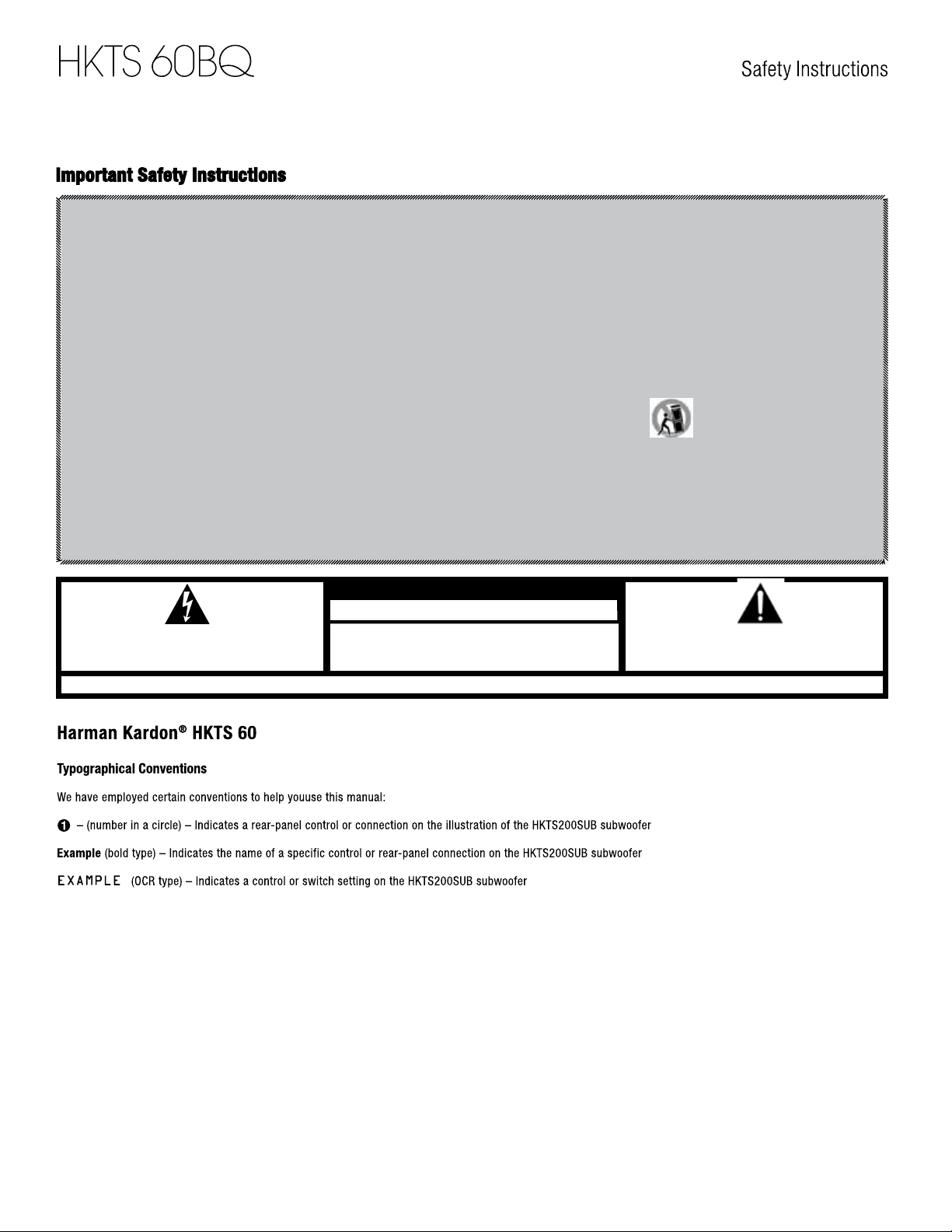
THE LIGH TNING FLA SH W ITH A N AR ROWHE AD SY MBOL, WIT HIN A N
EQUI LATER AL T RIANG LE, IS INTE NDED T O ALE RT TH E USER TO TH E PRE SENCE
OF UN INSUL ATED "DA NGERO US VOLTAG E" WITH IN THE P RODUCT 'S ENCL OSURE
THAT MAY BE O F SUFF ICIEN T MAGN ITUDE TO CON STITU TE A RI SK OF E LECTR IC
WARN ING: TO REDUC E T HE R ISK OF F IRE OR E LECTR IC S HOCK, DO NOT EXPO SE T HIS
APPA RATUS TO RA IN OR MOIST URE.
RISK OF ELECTRIC SHOCK
DO NOT OPEN
SEE MA RKING ON BAC K OF PRODUC T.
CAUTION
THE EXC LAMAT ION POINT WI THIN AN EQUI LATER AL TRIAN GLE IS INTEN DED
TO ALE RT THE USER TO T HE PRESE NCE OF IMPO RTANT OPE RATING
AND MAI NTENA NCE (SER VICING ) IN STRUC TIONS IN THE LITE RATUR E
ACCO MPANY ING THE PRO DUCT.
2
Page 3

3
Page 4
HKTS 60BQ
1
2
3
4
5
6
7
Connections
8
9
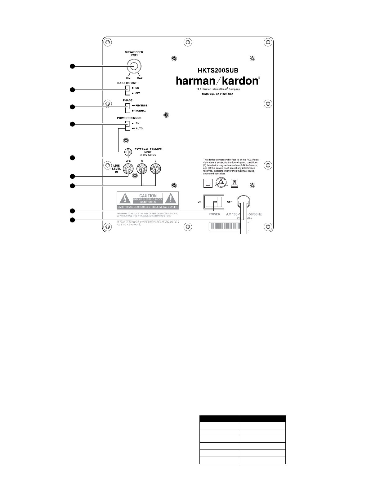
0 Subwoofer Level Control: Use this control to adjust the HKTS200SUB’s
volume. Turn clockwise to increase the volume; turn counterclockwise
to decrease the volume.
1 Bass Boost Switch: Set this switch to ON to enhance the HKTS200SUB’s
low-frequency performance. Set this switch to O FF for normal low-frequency
performance.
2 Phase Switch: This switch determines whether the HKTS200SUB’s piston-like action
moves in and out in phase with the satellite speakers. If the subwoofer were to play out
of phase with the satellite speakers, the sound waves from the satellites could cancel
out some of the subwoofer’s sound waves, reducing bass performance and sonic
impact. This phenomenon depends in part on the placement of all the speakers in the
room. In most cases the Phase Switch 2 should be left in the NORMAL position.
However, it does no harm to experiment, and you can leave the Phase Switch 2 in the
position that maximizes bass response and impact.
3
Power On Mode S witch : When this swi tch is set in t he A UTO position and
when the Power Switch 7is set to ON, the HKTS200SUB will automatically
turn itself on when it receives an audio signal and will enter the standby mode
after it has received no audio signal for about 15 minutes. When this switch is set
in the ON position, the HKTS200SUB will remain on whether or not it is receiving
an audio signal. An LED light on the HKTS200SUB’s top panel indicates whether
the subwoofer is in the on or standby state:
•WhentheLEDisilluminatedwhite,theHKTS200SUBisturnedon.
•When theLED is notilluminated, theHKTS200SUBisin standbymode.When
the Power Switch 7 is set to OFF , the LED will not be illuminated, no matter what setting the Power On Mode Switch 3is in.
4
External Trigger Input: Use the mini-plug of the supplied combination LFE and trigger cable to connect the External Trigger Input to the
trigger output of another compatible component. Whenever the HKTS200SUB's amplifier detects a trigger signal between 3V and 30V (AC or
DC), the amplifier will turn on. The amplifier will turn off after the trigger
signal ceases, even when the Power On Mode Switch 3is in the AUTO
position.
5
Line-Level LFE In Connector: Use the LFE (purple) connector of the supplied
combination LFE and trigger cable to connect the Line-Level LFE In Connec-
tor 5 to the dedica ted subwoofer output of a receiver or preamp processor.
This input bypasses the HKTS200SUB’s internal crossover circuitry, so use it
only with a subwoofer output that has been low-pass filtered. If your receiver or
preamp/processor does not have a dedicated subwoofer output that is low-pass
PL00 04-01 0 01
filtered, use the HKTS200SUB’s Line-Level L/R In Connectors 6 instead.
6 Line-Level L/R In Connectors: Use these connectors if your receiver or pre-
amp/processor does not have digital surround-sound decoding or a subwoofer
output that is low-pass filtered.
•Ifyourreceiverorpreamp/processorhasaseparatesubwooferoutput,usethe
LFE (purple) connector of the supplied combination LFE and trigger cable to
connect it to either one of the HKTS200SUB’s Line-Level L/R In Connectors.
•If your receiver or preamp/processor does not have a separate subwoofer
output, use two Y-adapters (not supplied). Connect an adapter’s single end to
the unit’s preamp output for that channel. Connect one of the adapter’s dual
ends to the main amp input for that channel, and connect the adapter’s other
dual end to one of the HKTS200SUB’s Line-Level L/R In Connectors. Repeat
the process with the other Y-adapter, preamp channel, main amp input and
HKTS200SUB Line-Level L/R In Connector.
7 Power Switch: Set this switch in the ON position to turn the HKTS200SUB on.
The subwoofer will then be either on or in standby mode, depending on the setting of the Power On Mode Switch 3 .
8 Power Cord (Non-Detachable): After you have made and verified all subwoofer
and speaker connections described in this manual, plug this cord into an active,
unswitched electrical outlet for proper operation of the HKTS200SUB. DO NOT
plug this cord into the accessory outlets found in some audio components.
Color-Coding System
The HKT S 60 uses the channel colo r-co ding system est ablished by the CEA to
make set ting up your home theater speaker sys tem as ea sy as possible. The
HK TS 60 system includes speaker wires with color bands on each end.
Speaker Position Wire C olor B and
Fro nt Lef t
Fro nt Right
Cen ter
Sur round L ef t
Sur round R igh t
Subwoofer
4
Whi te
Red
Gre en
Blue
Gray
Pur ple
Page 5
0 – 2ft
HKTS 60BQ
Speaker Placement
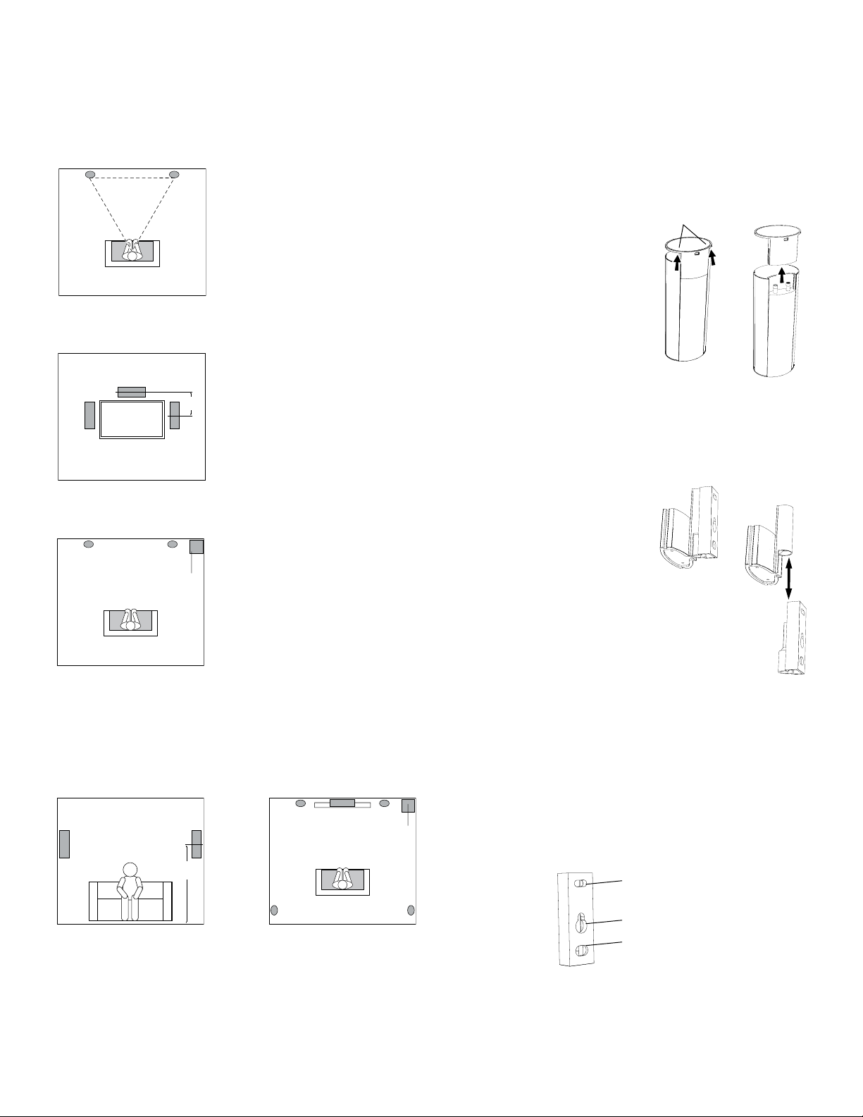
Placing the Front Speakers
Place the front speakers the same dis-
Front Left
Speaker
tance from each other as they are from the
Front Right
Speaker
listener’s position. Place them at about
the same height from the floor as the
listener’s e ars will be. They also can be
angled toward the lis tener.
Placing the Center Speaker
Place the center speaker slightly behind the front
left and front right speakers (farther away from
the listener). Its center should be no more than
two feet (61cm) above or below the tweeters of
0 - 2 ft
(0 - 61cm)
the front left and front right speakers. If you have
a CRT television (that is, not a flat screen), it may
be convenient to set the center speaker on top of
the television set.
Front Left
Speaker
Center
Speaker
TV
Front Right
Speaker
Placing the Subwoofer
Front Left
Speaker
Front Right
Speaker
Subwoofer
Since our ears do not hear directional sound
at the low fr equencies where the subwoo fer
operates, it will perform well from just ab out
any location in your room. However, you are
likely to hea r the best bass reproduction
when the subwoofer is placed in a corner
along t he same wall as the fr ont left and
fro nt right speakers. You can experiment
wit h subwo ofe r placement by temporarily
placing the subwoofer in the listening
positi on and playing music with str ong bas s
content. Move around t o various locations
in the room while the sys tem is playing, and
listen until you find the locati on where
the bass performance is best. Place the
subwoofer in t hat location.
Mounting Options for Satellite
and Center Speakers
Shelf Placement
You can place the satellite and center
speakers on sh elves. The satellite speakers have built-in bases for shelf placement. You can also remove the bases .
To remove a s atellite spe aker’s base, pull
it st raight off the speaker, as shown in
the illust ration. Applying even pressure to
bot h sides of the base will allow it to slide
off smoot hly.
Wall-Mounting: Satellite Speakers
IMPORTANT: Read the Speake r Connections
sec tio n, on page 7, before wall-mounting the satellit e speakers. You will need
to insert the s pea ker wires throu gh the
wall-mo unt brackets and connect the wires
to the spea ker s during the process of
installing the br ackets .
NOTE: If you are using your own spea ker
wire, it must be no thicker than the wire
supplied wit h the speakers. Thicker wire
will prevent the bracket from sliding onto
the speaker.
1. Decide on the locat ion for the speaker.
2. Remove the speaker’s bas e as explained
in S helf Pla cement, above.
3. Disassemble the wall-mount br acket by
sliding the two sections apar t, as show n
in t he illustr ation.
Apply Pres sure Evenly
to Both Sides of Base
Lift Base Straight
off Speaker
Pull Sections
Apart
Placing the Surround Speakers
Front Left
Surround Right
Speaker
Surround Lef t
Speaker
5 - 6 ft
(1.5m - 1.8m)
Speaker
Surround Lef t
Speaker
The t wo surround sp eakers should b e placed slightly b ehind the listening
positi on, facing each other, and, ideall y, should be 5 – 6 feet (1.5m – 1.8m ) from the
floor. An alternate location would be on a wall behind the listening position, facing
for ward. The surr ound speakers should not call attention to t hemselves while they’re
playing. Experiment with their placement unt il you hear a dif fuse, ambient s ound
accompanying the program material heard from the front left , front right and
center spe akers.
Front Right
Speaker
Subwoofer
Surround Right
Speaker
4. Attach the wall portion of the w all-mount bracket onto the wall using har dwa re that is app ropria te for the wall’s cons truction and
materials. We recommend first anchoring the bracket using i ts keyhole, then
attaching it wit h another anchor through its top opening, as sh own in the
illustration. Note that the s atellite speakers weigh 3.4 lb (1.55kg ). Be sure to
use har dware that can support this weight.
Top Opening
Keyhole Opening
Bottom Opening
5
Page 6

HKTS 60BQ
Speaker Placement
NOTE: If you’re r unning the speaker wire through t he wall, you can bring it out
directly behind the bracket location and in ser t it through the bot tom opening in
the wall por tion of the bracket, as shown in the illustration. R unning the wire in
this way will keep the wire completely hidden from view once the inst allati on is
complete.
Insert Wir e into
Bottom Opening
Bring Wire out
through Here
5. If you’re not running the speaker wire through the w all, inser t it through the
wall portion of the bracket, as shown in the illustration.
6. Pass the speaker wire through the speaker portion of the wall-mount bracket,
as shown in the illustration.
8. Connect the speaker wire to the speaker terminals as shown in
the illustration:
a) Press down on the top of the terminal to open the connection hole.
b) Insert the wire’s bare end all the way into the hole.
c) Release the terminal to secure the wire.
Insert the conductor with the colored band into the speaker’s red ( + ) terminal,
and insert the other conductor into the speaker’s black ( – ) terminal.
–
+
A. Push Down on Cap
to Open Hole
B. Insert Bare Wire
into Open Hole
C. Release Cap
to Secure Wire
IMPORTANT: Make sure the ( + ) and ( – ) bare wires do not touch each other or
the other terminal. Touching wires can cause a short circuit that can damage
your receiver or amplifier.
9. Slide the speaker portion of the wall-mount bracket onto the speaker as shown in the
illustration. Fit the grooves on the bracket onto the rails in the speaker, and apply
even pressure on both sides of the bracket so it slides straight onto the speaker.
•Pushthebracketallthewayontothespeakeruntilitsnapsintoplace.
•Pullanyslackspeakerwirebackthroughthebracketasyouslidethe
bracket onto the speaker.
Push Down Evenly on Both Sides of Bracket
Fit Bracke t Grooves
onto Speaker Rails
Bring Wire In
through Here
Bring Wire out
through Here
7. If you have not alread y removed the speaker’s base, do so by pulling i t st raight
off the speaker, as shown in the illu stration. Applying even pressure to both
sides of the base will allow it to slide of f smoothly.
Apply Pres sure Evenly
to Both Sides of Base
Lift Base Straight
off Speaker
CAUT ION: Before mak ing speaker connections, be sure that your receiver or
amplifier is turned O FF and it s AC cord is unplugged from the AC outlet.
10. Slide the speaker onto the bracket’s wall section, as shown in the illustration. Pull
any slack speaker wire back through the bracket’s wall section.
Slide Speaker
onto Wall-Mount
Bracket
11. Fit the metal stop plate into the recess on the bottom of the bracket with the pad
facing the bracket, and fasten it to the bracket using two of the supplied screws.
Fastening it will prevent the speaker from detaching from the bracket and will hold
the speaker’s position as you rotate it.
Stop Plate
Supplied Screws
6
Page 7

HKTS 60BQ
Speaker Placement
Wall-Mounting: Center Speaker
1. Decide on the location for the speaker.
2. Attach the center speaker wall-mount bracket to the wall using hardware that is
appropriate for the wall’s construction and materials. Attach the anchors through
the holes shown in the illustration.
Use These Holes
to Attach Bracket
to Wall
NOTE: The center speaker weighs 3.3 lb (1.5kg). Be sure to use hardware that can
support this weight.
CAUTION: Before making speaker connections, be sure that your receiver or amplifier is turned OFF and its AC cord is unplugged from the AC power source.
3. Connect the speaker wire to the speaker terminals. Press down on the top of the
terminal to open the connection hole, insert the wire’s bare end all the way into
the hole and release the terminal to secure the wire. Insert the conductor with the
colored band into the speaker’s red ( + ) terminal, and insert the other conductor
into the speaker’s black ( – ) terminal, as shown in the illustration.
A. Push Down on Cap
to Open Hole
B. Insert Bare Wire
into Open Hole
–
+
C. Release Cap
to Secure Wire
Speaker Connections
CAUT ION: Before making speaker connections, be sure that your receiver or
amplifier is turned OFF and its AC cord is unplugged from the AC power outlet.
Speakers and receivers/amplif ier s have corre sponding ( + ) and ( – ) connection terminals. Mo st elec tronic s ma nuf acturers, including H arman K ardon, use
red to denote t he ( + ) terminal and black for the ( – ) terminal. Newer Harman
Kardon receivers conform to the C EA standard and therefore use a color other
than red to denote the ( + ) terminal for some speaker positions. S ee the table
in C olor-Coding System, on page 4.
Each speaker wire included with your system has colore d bands at bot h ends
of the ( + ) conductor, and the subwoofer cable has purple connecto rs tha t
cor res pond to the color of the HKT S2 00 SU B’s LFE jack. This system helps
ensure t hat the spea ker in each locat ion is connected to t he correct receiver or
amplifier terminals. In additi on to the colored ba nds at each end, each spe aker
wire’s ( + ) terminal has r ibs molded into its insulation to help you identify it .
It is very important to c onnect each speaker ident ica lly : ( + ) on the speaker to
( + ) on the receiver or amplifier, and ( – ) on the speaker to ( – ) on the receiver
or amplifier. Miswiring one or more speakers results in thin sound, weak b ass
and a poor st ereo image. With the advent of multichannel surround-sound systems, conne cting all of the speakers in your system corre ctly is ver y impor tant
to achieving the proper ambience and direc tio nality of the progr am materia l.
To connec t the speaker wire to the terminals on the satellite and center speakers , pres s d own on the top of the terminal to open the connection hole, inser t
the wire’s bare end all the way into the hole, and release the terminal to secure
the wire. Inser t the conduc tor with the colored band into the speaker’s red ( + )
terminal, and insert t he other conductor into the speaker’s black ( – ) terminal,
as shown in the illustra tion.
Important: Make sure the ( + ) and ( – ) bare wires do not touch each other or the
other terminal. Touching wires can cause a short circuit tha t can damage your
receiver or amplifier.
4. Using two of the supplied screws, attach the center speaker to the bracket, as
shown in the illustration.
Wall-Moun t
Bracket
Supplied Screws
–
+
A. Push Down on Cap
to Open Hole
IMPORTANT: M ake sure the ( + ) and ( – ) bare wires do not touch each other
or the other terminal. Touching wire s can cause a short circuit t hat can damage
your receiver or a mplifier.
B. Insert Bare Wire
into Open Hole
C. Release Cap
to Secure Wire
Connecting Satellite Speakers With Supplied
Wall-Mount Brackets
Follow the instructions in Wall-Mounting: Satellite Speakers,
on page 5, and Wall-Mounting: Center Speaker, opposite.
Connecting Satellite Speakers with Supplied
Bases
1. Remove the speaker ’s base (see Shelf Placement,
on page 5).
2. Pass the speaker wire through the opening in the
speaker’s b ase.
3. Connect the speaker wire as described above.
4. Reat tach the speaker’s bas e, as shown in the illustration.
7
Page 8

HKTS 60BQ
Setup Instructions
Front Left
Speaker Cable
(White Bands)
+ – + –
+ –
+ –
Center
Center
Front Right
Speaker Cable
(Red Bands)
+–+–
Front Left Front Right
Speaker Cable
(Green Bands)
+–
SURROUNDFRONT CENTER
RIGHT
LEFT
+ –
+ –
+ –
SUB
LFE OUT
PL0004-01001
Receiver
LFE/Trigger Cable
Surround Left
Speaker Cable
(Blue Bands)
+– +–
(Purple Ends)
Surround Right
Speaker Cable
(Gray Bands)
Surround
Left
Connecting the Subwoofer to a Receiver or
Preamp/ Processor Wit h a Dedicated Subwoofer Output
Use this installation method for receiver s and pre amp /processor s that have a
dedicated subwo ofer output with low-pass filtering (also called bass management) .
If the dedicated subwoofer output does not have low-pas s filtering, follow the
instru ctions in Connecting the Subwoofer to a Receiver or Preamp /Processor With
Line Outputs, on page 9.
Use the LFE (purple) connector of t he supplied c ombination LFE and trigger
cable to connect the HKTS200SUB’s Line-Level LF E I n Jack 5 to the dedicated
subwoofer out put (or L FE output) of your receiver or preamp/pr ocessor.
Subwoofer
Surround
Right
Connect each satellite speaker and the center sp eaker to the cor responding
speaker terminals on your receiver or a mplifier.
Configure your receiver or prea mp /process or’s setup menu for Subwoofer ON,
and set the front left, front right, center an d surround speakers to Small. After
you have mad e and verified all connections, plug the H KTS200SUB’s AC Power
8
Cor d
8
into an active AC outlet.
Page 9

Front Left Front Right
Center
HKTS 60BQ
Setup Instructions
Front Left
Speaker Cable
(White Bands)
Center
Speaker Cable
(Green Bands)
+–
SURROUNDFRONT CENTER
RIGHT
LEFT
+ –
+ –
+ –
LINE-LEVEL
OUTPUTS
L R
+ – + –
+ –
+ –
Receiver
Surround Left
Speaker Cable
(Blue Bands)
Front Right
Speaker Cable
(Red Bands)
+–+–
PL0004-01001
Subwoofer
RCA Cable
(Not Supplied)
(Red and White Ends)
+– +–
Surround Right
Speaker Cable
(Gray Bands)
Surround
Left
Connecting the Subwoofer to a Receiver
or Preamp /Processor With Line Outputs
Use this inst allation method for receivers and preamp/ processors that do not have
a dedicated subwoofer output but do have preamp-level (volume-controlled) line
out put s. If the receiver or preamp/ processor has a dedicated subwoofer output
wit h low-pass filtering, see Connecting the Subwoofer to a Receiver or Preamp/
Processor With a Dedicated Subwoofer Output, on page 8.
If you’re connecting to a receiver with left and right line ou tputs that are not
connected to amplifier inputs , connect the L FE ( pur ple ) connec tor o f the supplied
combina tio n LFE and trigger cable to one of those outputs and to ei ther of the
HK TS 20 0S UB’s Lin e-Level L /R I n Conne ctors 6. Use a second RCA cable (not
supplied) to connect the other receiver or preamp line output to the other of the
HK TS 20 0S UB’s Line-Le vel L/R In C onnec tors 6.
If you’re connecting to a rec eiver or preamp /proc essor with left and righ t line
out put s that are connected to amplif ier front lef t and front righ t input s, connect
Surround
Right
the single line outputs. Connect one of the Y-adapter’s double ends to the
HK TS 20 0S UB’s Line-Le vel L/R In C onnec tors 6, and connect the other
double end to your amplifier’s front left and right inputs.
Connect each satellite speaker and the center speaker to the correspond-
ing speaker terminals on your receiver or amplifier.
Configure your receiver or preamp /processor’s setup menu for Subwoofer
ON, and set the front left, front right , center and s urr ound speakers to Small.
After you have mad e and verified all connections, plug the HK TS 20 0S UB’s
AC P owe r Cord 8 in to an acti ve AC outlet.
9
Page 10

Receiver
HKTS 60BQ
Setup Instructions
SURROUNDFRONT CENTER
+ –
+ – + –
RIGHT
12V
TRIGGER
OUTPUT
+ –
+ –
LEFT
LFE SUB
OUTPUT
+ –
+ –
Subwoofer
Trigger Cable
(Black Ends)
Connecting to a Trigger-Voltage Source
If your preamp/ processo r or anot her audio/video component has a trigger-vol tage
connection that supplies bet ween 3V and 30V ( AC o r DC ), c onnect i t to the HK TS 200SUB’s External Trigger Input 4. If the component’s trigger-voltage connection
has a 3.5mm mini jack , you can use the supplied combination LFE /trigger cable to
make the conne ction.
PL00 04-0 1001
NOTE: Please do not connect the subwoofer ON/ OFF trigger c able to the R emote
Control Output ( IR Out) of your home cinema system or sur round r eceiver. Doing
so could lead to malfunc tio n.
10
Page 11

HKTS 60BQ
Operation
Turning the Subwoofer On and Of f
Set the HKT S200SUB’s Power S witch 7 to the ON position.
•If t he Power On Mode Switch 3 is set to AU TO, the HKTS200 SU B will
automatically turn it self on when it r eceives an audio signal, and it will go int o
standby mode after it has received no audio signal for 15 minutes. The HK TS200SUB’s LE D will glow white when the subwoofer is on, and will not be illuminated w hen the subwoofer is in standby.
•IfthePower On Mode Swit ch 3 is set to O N , the H KTS200SUB will remain
on at all times. T he HK TS200SUB’s LED w ill glow white.
•Ifthe Ex te rnal Trigger Input 4 is connected to a trigger voltage source, the
HK TS 20 0S UB will turn on whenever a trigger volt age is pre sen t, and will t urn
off after the trigger voltage ceases, regardle ss of the position of the Power On
Mod e Switch 3.
If you will be away from home for an extended period o f time, or if you will not be
using the subwoo fer fo r a n extende d p eri od, switch t he Power Switch 7 to the
OF F Posi tio n.
Subwoofer Adjustments : Volume
Use the Subwoofer Level Contr ol 0 to set t he H KTS200SUB’s volume. Turn the
kno b clockwise to increas e the subwoofer’s volume ; turn the k nob co unterclockwise to decrease the subwoofer ’s volume.
Operating Instructions
Subwoofer Adjustments : Phase
The Phase Sw itch 2 determines whether the HK TS200SUB’s piston-like action
moves in and out in phase wi th the satellite speakers. If the subwoofer were to
play out of phase with the satellite spea ker s, the sound waves from the satellites
could cancel out sound waves fr om the subwoo fer, reducing bass perf ormance
and sonic impac t. This phenomenon depends in par t on the placement of all the
speakers in the room.
Although in most cas es the Phase S witch 2 should be lef t in the NOR M AL
positi on, there is no absolutely correct sett ing for the Phase Switch 2. When
the H KTS200 SU B is properly in phase with the s atellite speakers, t he audio will
be clearer, have maximum impact and make percussive sounds like drums, piano
and plucked strings sound more lifelike. The best way to set the P hase Sw itch
2
is to listen to music t hat you know well and set t he switch in the position that
gives drums and other percussive sounds maximum impact.
Subwoofer Adjustments : Bass Boost
When set to the ON position, the Bas s Boost Switch 1 enhances low-frequency
per formance, resulting in bass with more impact, which you may prefer while
watching movies or listening to music. There is no ha rm in experimenting wi th this
control. S et ting the switch to th e O FF pos ition will ret urn normal low-frequency
per formance.
11
Page 12

HKTS 60BQ
Troubleshooting
Troubleshooting
This unit is designed for trouble-free operation. Most problems that users encounter are due to operating errors. So if you have a problem, first check this list for a possible solution.
If the problem persists, consult your authorized Harman Kardon service center.
Problem Solution
If there is no sound from any of the speakers: • Check that the receiver/amplifier is on and a sour ce is playing.
• Make sure that all wires and connections be tween the receiver/amplif ier
and the speakers are connected properly.
• Make sure that the speaker wires are not frayed, cut or punctured.
• Review the proper opera tio n of your re ceiver/amplifier.
If there is no sound coming from one of the speakers: • Check that the balance cont rol on your receiver/amplifier is not set all the way
If there is no sound coming from the center s pea ker: • Check your re ceiver/amplifier’s speaker se tup procedure to make sure that
You can find additional troubleshooting informat ion in the FAQs link on the Support page at www.harmank ardon.com.
to one channel.
• Check your re ceiver/amplifier’s speaker se tup procedure to make sure that
the sp eaker in question has been enabled a nd its volume level has not be en
turned all the way down.
• Make sure that all wires and connections between the recei ver/amplifier
and the speaker are connected proper ly.
• Make sure that the sp eaker wires are not frayed, cut or punctured.
the center speaker has been enabled and its volume level has not been turned
all the way down.
• Make sure that all wires and connections between the receiver/amplifier
and the cente r speaker are connected properly.
• Make sure that the sp eaker wires are not frayed, cut or punctured.
• If your receiver is op erating in Dolby
center speaker is not set to Phantom.
®
P ro Logic® mode, make sure that the
12
Page 13

HKTS 60BQ
Specifications
HKTS 60 System
Frequency response 45Hz – 20 kHz ( – 6dB)
SAT-TS60 Satellites
Recommended power 20 ~ 150 watts
Impedance 8 ohms nominal
Sensitivity 83dB @ 2.83V/1 meter
®
Tweeter One 1" ( 25mm) CMMD
Midrange Dual 3" (75mm ) flat-dia phr agm dri vers,
Dimensions – including st ands ( H x W x D ) 11-25/32 " x 4-11/32" x 3-15/32"
Weight 3.4 lb (1.55kg)
video-shielded
video-shielded
(2 99 mm x 110mm x 88mm )
Lite dome,
Specifications
CEN-TS60
Recommended power 20 ~ 150 watts
Impedance 8 ohms nominal
Sensitivity 83dB @ 2.83V/1 meter
Tweeter One 1" ( 25mm) CMMD Lite dome,
Midrange Dual 3" (75mm ) flat-dia phr agm dri ver s,
Dimensions – including st ands ( H x W x D ) 4-11/32" x 10-11/32" x 3-15/ 32"
Weight 3.3 lb (1.5kg)
video-shielded
video-shielded
(110mm x 272mm x 88mm)
HKTS200SUB Subwoofer
Input rating AC 100 – 120V, 50/ 60Hz, 200W
Amplifier power 200 wa tt s R MS
Bass 8" woofer, s ealed enclosure
Ex ternal trigger input voltage 3 ~ 30 volts A C/DC
Dimensions (H x W x D) 13-29/ 32" x 10-1/2" x 10-1/2"
Weight 19.8 lb ( 9kg)
(3 53mm x 267mm x 267mm)
13
Page 14

Harman Consumer, Inc.
8500 Balboa Boulevard, No rthridge, CA 91329 USA
516.255.4545 (USA only)
Made in P.R.C.
© 2010 Harman Intern ation al Industries, Incorpor ated. All rights reserved.
Features, specifications an d appearance are su bject to change without
notice. Harman Kardon an d CMM D are trademar ks of Harman Intern ati ona l
Ind ust rie s, Incorporat ed, registe red in the United S ta tes and /or oth er
cou ntr ies .
CE A is a regis ter ed tr ade mar k of th e Consum er El ect ronics Ass ociation.
Dol by a nd P ro Logic a re r egistered tra demark s of Dolby L abora tor ies .
DTS is a re gis ter ed t rad emark o f Digit al Theater Sy stems, Inc.
Par t # 950- 0302-001
www.harmankardon.com
 Loading...