

Page 1
Thank you for purchasing a Harman Kardon DPR 1001.This Quick-Start
Guide will help you with a basic system installation. For detailed information
on any step,please refer to the Owner’s Manual pages referenced in this
guide.We strongly recommend that you read the Owner’s Manual for
complete details on how to install, configure and operate the DPR 1001,
as well as for the important safety information it contains.
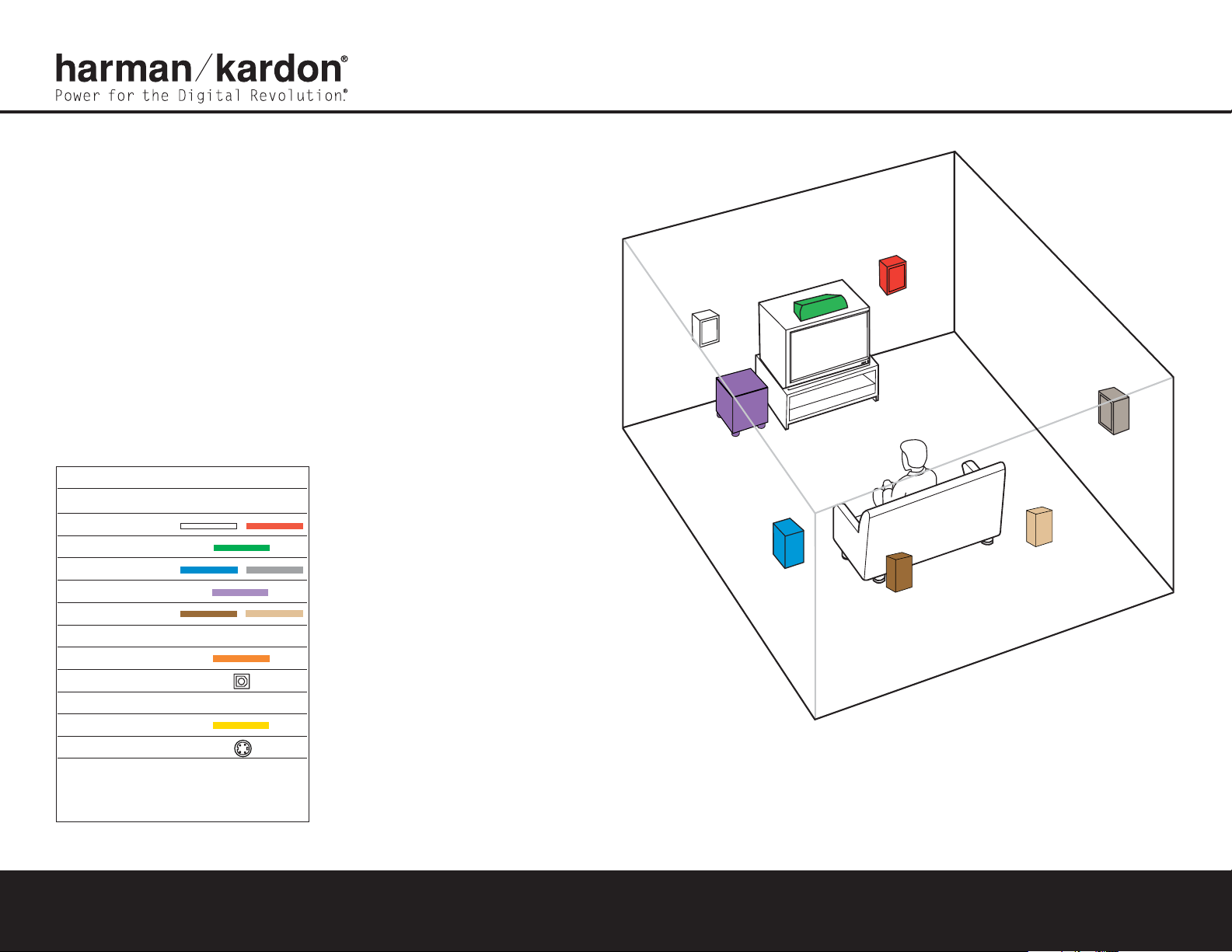
Figure 1 – Speaker Placement
The colors shown for each speaker correspond to
the matching output terminal connection on the back
of the DPR 1001 (see page 8).
FRONT
LEFT
SPEAKER
(White)
SURROUND
BACK
LEFT
SPEAKER
(Brown)
SURROUND
BACK
RIGHT
SPEAKER
(Tan)
CENTER
SPEAKER
(Green)
SUBWOOFER
(Purple)
SURROUND
LEFT
SPEAKER
(Blue)
FRONT
RIGHT
SPEAKER
(Red)
SURROUND
RIGHT
SPEAKER
(Gray)
Step 1. Place your speakers in the listening room
(see page 16).
SPEAKER PLACEMENT
Connections Color Guide
Audio Connections Left Right
Front
Center
Surround
Subwoofer
Surround Back
Digital Audio Connections
Coax
Optical
Video Connections
Composite
S-Video
Match the colored jacks on the DPR 1001 to the appropriate
jacks on your source equipment or speakers.The colors are
standardized, but not all equipment or connectors use them.
DPR 1001 QUICK-START GUIDE
Page 2
DPR 1001 QUICK-START GUIDE
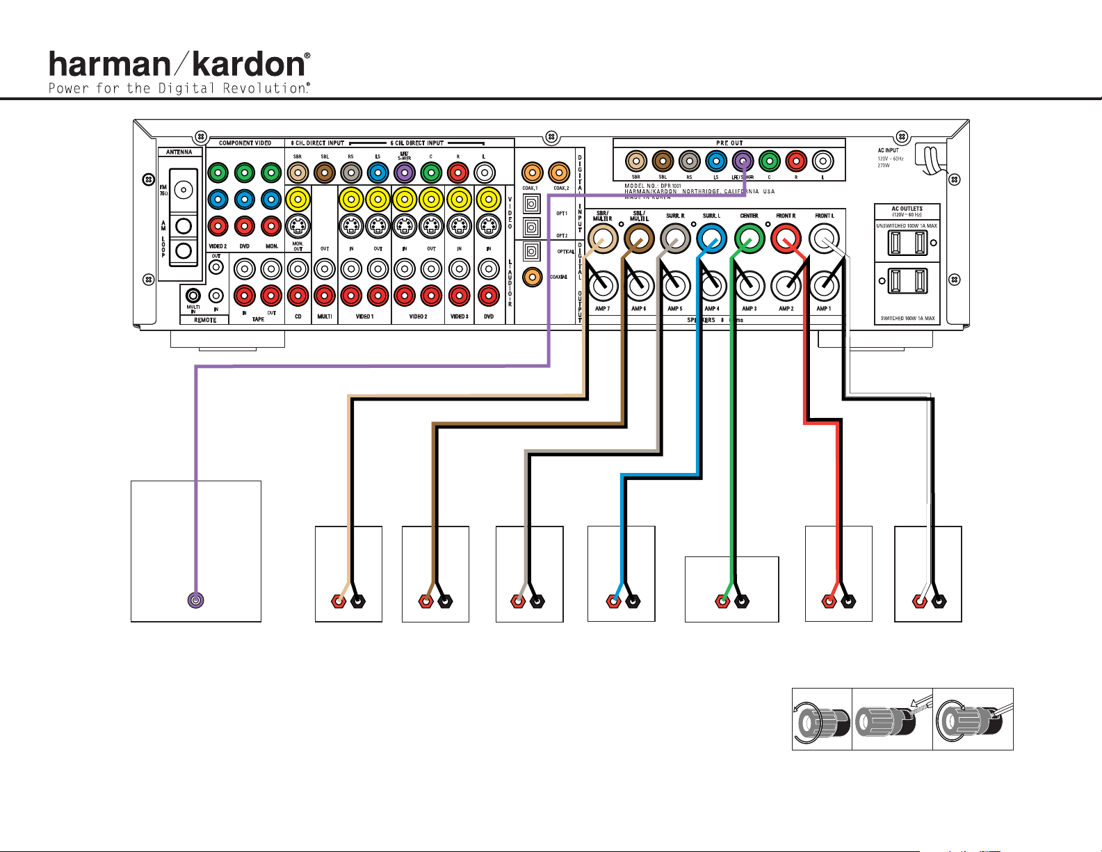
Figure 2 – Speaker Connections
Step 2. Connect the speakers to the receiver: red (+)
on speaker to colored (+) on receiver and
black (–) to black (–). (See page 14.)
Step 3. Connect the Subwoofer Pre-Out jack to
the Line-In jack on your subwoofer (see
page 14).Adjust the settings on the
subwoofer as needed.
Figure 3 – How to Use the Binding-Post
Speaker Terminal
LINE IN/SUB/LFE
SUBWOOFER
_
+
SURROUND BACK
RIGHT SPEAKER
_
+
SURROUND BACK
LEFT SPEAKER
_
+
SURROUND
RIGHT SPEAKER
_
+
SURROUND
LEFT SPEAKER
_
+
CENTER SPEAKER
_
+
FRONT RIGHT
SPEAKER
_
+
FRONT LEFT
SPEAKER
Page 3

SPEAKER AND AUDIO CONNECTIONS
AUDIO RECORDER
Step 4. Connect AM and FM antennas (as shown above) (see page 14).
Step 5. Connect source components,as shown in Figures 4 and 5, and the
Device Connection Options chart on the back of this Guide (see
pages 14–15).
AUDIO connections: Right channel (red) on source to right (red)
on AVR,and left channel (white) on source to left (white) on AVR.
DIGITAL AUDIOconnections, if available: Choose either coax
(orange) to coax (orange) OR optical to optical for each device.
The Coax 1 input defaults to the DVD player, but may be reassigned.
Assign the other digital inputs and outputs as appropriate for your
equipment (see Step 7).
VIDEO connections: Choose component (Y/Pb/Pr – green/blue/
red), composite (yellow) or S-Video (4-pin) for each video source.
Connect the component, composite and S-Video Monitor outputs to
your Video Monitor (TV).Switch your TV set’s input to match the type
of video used for the currently selected source.
Step 6. Plug all components into AC power outlets.The outlets on the back
of the DPR 1001 should be used
only for low-current products,such
as CD or DVD players,and the total should not exceed 100 watts.
Basic Receiver Configuration
Step 7. Select digital inputs: If your DVD is connected to Coax 1, no adjust-
ment is needed. For any other digital-device connections,use the
front-panel Digital Select button and the arrow buttons to select an
optical or coax digital input (see pages 18 and 27).
Step 8.
Select a surround mode: Press the Surround Mode button on the
front panel to select Dolby
®
Pro Logic®II – Movie.(You may select
other modes later as you become familiar with the DPR 1001; see
pages 18–19 and 25–28.)
Step 9.
Speaker Optimizer: If your system has 8-ohm speakers, no adjustment is needed. For 6-ohm or 4-ohm speakers,change the Speaker
Optimizer setting as shown on page 17 of the Owner’s Manual.
Step 10.
Configure speakers: No action is needed if you have seven “small”
satellite-type speakers and a subwoofer. Otherwise,press the
Speaker button, and then the Set and arrow buttons to select the
correct speaker choices for your system (see pages 19–21).
Step 11.
Set the Output Levels with EzSet™: Set the Volume to –15dB.Sit
in the listening position and hold the remote in front of you at shoulder level, pointing it at the DPR. Press the EzSet button on the
remote,and then the SET button when it lights red. Following the
instructions in the remote’s LCD display, press the button on the
remote until the display shows the number of speakers in your system
and then press the SET button again. Hold the remote steady until
the LCD display flashes a COMPLETE message (see page 22).
Step 12.
Your system is configured – sit back and enjoy!
Figure 4 – Audio Connections
Dashed lines (––––) indicate coax and optical
digital audio connections. Choose either type
(but not both) for each digital audio source.
CD PLAYERAM AntennaFM Antenna
L R Optical Coax
REC/IN
PLAY/OUT
Page 4

DVD
PLAYER
VCR (Video 1)
In/Rec
Out/Play
L R VIDEO
Optical Coax
L R Video S-Video
Cable or Sat or HDTV Set-Top Box (Video 3)
OUT
L R Video S-Video
Optical Coax
TV or Video Monitor (Video 2)
OUT
IN
L R Video S-Video Component Video
Y Pb Pr
Component Video
Y Pb Pr
Component Video
Y
Pb
Pr
VIDEO CONNECTIONS
Device Connection Options: Recommended connections are shown in red, but connections may be made to best fit your system requirements.The Video 4, Coax 3 and Optical 3 inputs are on the front panel of the receiver.
Device Input Name Audio Input Connections Audio Output Connections Video Connections
CD Player CD CD L/R Inputs, Optical Digital 1 or 2, or Coaxial Digital 1 or 2 Not required Not required
DVD Player DVD Coaxial Digital 1 or 2, Optical Digital 1 or 2, or DVD L/R Inputs Not required DVD Component, Composite or S-Video
VCR Video 1 Video 1 L/R Inputs Video 1 L/R Outputs Video 1 Composite or S-Video Input and Output
Cable Box or Satellite Receiver Video 3 Video 3 L/R Inputs,Optical Digital 3*, or Coaxial Digital 3* Inputs Not required Video 3 Composite or S-Video Input
Audio Recorder Tape Tape L/R Inputs,Optical Digital 1/2** or Coaxial Digital 1/2** Inputs Tape L/R Outputs,Digital Optical** or Coaxial Outputs** Not required
TV or Projector Video 2 or 3 Video 2 or 3 L/R Inputs Not required Monitor-Out Component, Composite and/or S-Video
*
Check with your cable company to determine whether digital audio is available for all channels.It may be necessar y to make BOTH analog and digital connections if it is not.**Digital audio recorders only.
250 Crossways Park Drive,Woodbury, New York 11797 www.harmankardon.com © 2003 Harman International Industries,Incorporated Part No.: YBAP-17020-ZZ4-01
Figure 5 – Video Connections
Dashed lines (––––) indicate coax and optical digital audio connections. Choose either type (but not both) for
each digital audio source.
Dotted lines (••••) indicate component, composite or S-Video connections. Component video is the preferred
connection when available, but you may use any of the three types (but not more than one). When component,
composite and S-Video sources are connected to the DPR you must also connect all outputs from the DPR to your TV.
Power for the Digital Revolution.
®
®
 Loading...