

Page 1
System 13828
Open/Close
DVD 28
AUDIO/VIDEO
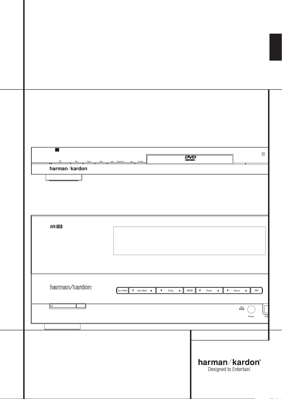
AVR 138 Audio/Video Receiver
DVD 28 Digital Versatile Disc Player
OWNER’S MANUAL
ENGLISH
Page 2
Table of Contents
2
AVR 138
3 Safety Information
3 Unpacking
4 Remote Control Functions
(AVR 138/DVD 28)
8 Front Panel Controls
10 Rear Panel Connections
12 Installation and Connections
12 Audio Equipment Connections
13 Video Equipment Connections
14 System Configuration
14 First Turn On
14 Settings to be Made
With Each Input Used
14 Input Setup
15 Speaker Setup
16 Surround Setup
16 Configuring the Surround Off
(Stereo) Modes
16 Stereo-Direct (Bypass) Mode
16 Stereo Digital Mode
16 Delay Settings
17 Night Mode Settings
17 Output Level Adjustment
19 Operation
19 Basic Operation
19 Source Selection
19 Controls and Use of Headphones
19 Surround Mode Selection
20 Digital Audio Playback
21 Selecting a Digital Source
21 Digital Status Indicators
21 Surround Mode Types
22 Night Mode
22 Tape Recording
22 Output Level Trim Adjustment
23 6-Channel Direct Input
23 Display Brigthness
23 Memory Backup
23 Tuner Operation
24 RDS Operation
25 Troubleshooting Guide
25 Processor Reset
DVD 28
26 Terminology
27 Features, Packing List
28 Front Panel Controls
29 Front Panel Information Display
30 Rear Panel Connections
31 Setup and Connections
31 Connecting to a TV Only
31 to a Dolby Digital/DTS
Amplifier/Receiver
33 Digital Audio Connections
34 Playback Basics
34 Basic Play
34 Playback Features
35 About DivX Movie Files
36 System Set-up
36 System Defaults
36 Set Up Menu
Declaration of Conformity
We, Harman Consumer Group, Inc.
2, route de Tours
72500 Château-du-Loir,
FRANCE
declare in own responsibility, that the product described in
this owner’s manual is in compliance with technical
standards:
EN 55013:2001 + A1:2003
EN 55020:2002 + A1:2003
EN 61000-3-2:2000
EN 61000-3-3:1995 + A1:2001
EN 60065:2002
Jurjen Amsterdam
Harman Consumer Group, Inc.
07/08
36 System Settings
37 Audio Settings
38 Audio Adjustments Submenu
39 Video Settings
40 Test Screen
40 Test Screen
40 TV Picture Adjustment
41 Player Menu
41 Using the Player Information Menu
41 Using the On-Screen Status Display
42 CD Playback
44 MP3, Windows Media and JPEG Playback
46 Troubleshooting Guide
47 Technical Specifications
48 Specifications
NOTE: This player is designed and manufactured
for compatibility with Region Management
Information that is encoded on most DVD discs.
This player is designed only for playback of discs
with Region Code 2, or for discs that do not
contain Region Code information. If there is any
other Region Code on a disc, that disc will not
play on the DVD.
2 TABLE OF CONTENTS
Typographical Conventions
In order to help you use this manual with the remote control, front-panel controls and rear-panel
connections, certain conventions have been used.
EXAMPLE – (bold type) indicates a specific remote control or front-panel button, or rear-panel
connection jack
EXAMPLE – (OCR type) indicates a message that is visible on the front-panel information display
– (number in a square) indicates a specific front-panel control
– (number in a circle) indicates a rear-panel connection
0
– (number in an oval) indicates a button or indicator on the remote.
Page 3
Safety Information
Important Safety Information
1. Read these instructions.
2. Keep these instructions.
3. Heed all warnings.
4. Follow all instructions.
5. Do not use this apparatus near water.
6. Clean only with a dry cloth.
7. Do not block any ventilation openings. Install
in accordance with the manufacturer’s instructions.
8. Do not install near any heat sources such as
radiators, heat registers, stoves or other apparatus (including amplifiers) that produce heat.
9. Do not defeat the safety purpose of the polarized or grounding-type plug. A polarized plug has
two blades with one wider than the other. A
grounding-type plug has two blades and a third
grounding prong. The wide blade or the third
prong is provided for your safety. If the provided
plug does not fit into your outlet, consult an electrician for replacement of the obsolete outlet.
10. Protect the power cord from being walked
on or pinched, particularly at plugs, convenience
receptacles and the point where they exit from
the apparatus.
11. Only use attachments/accessories specified
by the manufacturer.
12. Use only with the cart, stand, tripod, bracket
or table specified by the manufacturer or sold
with the apparatus.When a cart is used, use
caution when moving the cart/apparatus
combination to avoid injury from tip-over.
13. Unplug this apparatus during lightning
storms or when unused for long periods of time.
14. Refer all servicing to qualified service personnel. Servicing is required when the apparatus
has been damaged in any way, such as power
supply cord or plug is damaged, liquid has been
spilled or objects have fallen into the apparatus,
the apparatus has been exposed to rain or moisture, does not operate normally, or has been
dropped.
15. Do not expose this apparatus to dripping or
splashing and ensure that no objects filled with
liquids, such as vases, are placed on the apparatus.
16. To completely disconnect this apparatus
from the AC Mains, disconnect the power supply
cord plug from the AC receptacle.
17. The mains plug of the power supply cord
shall remain readily operable.
18. Do not expose batteries to excessive heat
such as sunshine, fire or the like.
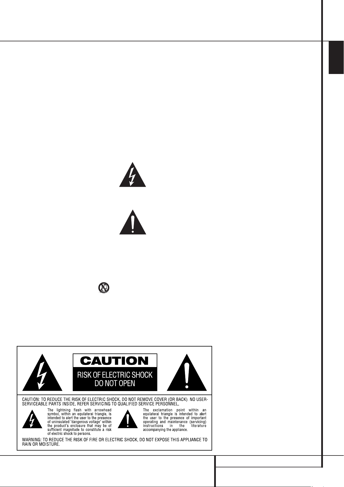
The lightning flash with arrowhead
symbol, within an equilateral triangle,
is intended to alert the user to the
presence of uninsulated “dangerous voltage”within the product’s enclosure that
may be of sufficient magnitude to constitute a
risk of electric shock to persons.
The exclamation point within an equi-
lateral triangle is intended to alert
the user to the presence of impor-
tant operating and maintenance
(servicing) instructions in the literature accompanying the product. WARNING:To reduce the
risk of fire or electric shock, do not expose this
apparatus to rain or moisture.
Do Not Open the Cabinet
There are no user-serviceable components inside
this product. Opening the cabinet may present a
shock hazard, and any modification to the
product will void your guarantee. If water or any
metal object such as a paper clip, wire or a
staple accidentally falls inside the unit, disconnect it from the AC power source immediately,
and consult an authorized service station.
Installation Location
■ To assure proper operation and to avoid the
potential for safety hazards, place the unit on
a firm and level surface.When placing the
unit on a shelf, be certain that the shelf and
any mounting hardware can support the
weight of the product.
■ Make certain that proper space is provided
both above and below the unit for ventilation.
If this product will be installed in a cabinet or
other enclosed area, make certain that there
is sufficient air movement within the cabinet.
Under some circumstances a fan may be
required.
■ Do not place the unit directly on a carpeted
surface.
■ Avoid installation in extremely hot or cold
locations, or an area that is exposed to direct
sunlight or heating equipment.
■ Avoid moist or humid locations.
■ Do not obstruct the ventilation slots on the
top of the unit, or place objects directly over
them.
Cleaning
When the unit gets dirty, wipe it with a clean,
soft, dry cloth. If necessary, wipe it with a soft
cloth dampened with mild soapy water, then a
fresh cloth with clean water. Wipe dry
immediately with a dry cloth. NEVER use
benzene, aerosol cleaners, thinner, alcohol or any
other volatile cleaning agent. Do not use
abrasive cleaners, as they may damage the finish
of metal parts.Avoid spraying insecticide near
the unit.
Moving the Unit
Before moving the unit, be certain to disconnect
any interconnection cords with other components, and make certain that you disconnect the
unit from the AC outlet.
Unpacking
The carton and shipping materials used to protect your new receiver during shipment were
specially designed to cushion it from shock and
vibration. We suggest that you save the carton
and packing materials for use in shipping if you
move, or should the unit ever need repair.
To minimize the size of the carton in storage,
you may wish to flatten it. This is done by
carefully slitting the tape seams on the bottom
and collapsing the carton. Other cardboard
inserts may be stored in the same manner.
Packing materials that cannot be collapsed
should be saved along with the carton in a
plastic bag.
If you do not wish to save the packaging
materials, please note that the carton and other
sections of the shipping protection are
recyclable. Please respect the environment and
discard those materials at a local recycling
center.
ENGLISH
SAFETY INFORMATION 3
Page 4
SETUP
138
28
a
q
t
`
z
x
y
p
g
j
k
m
n
o
s
u
w
v
b
d
c
f
r
e
7
8
l
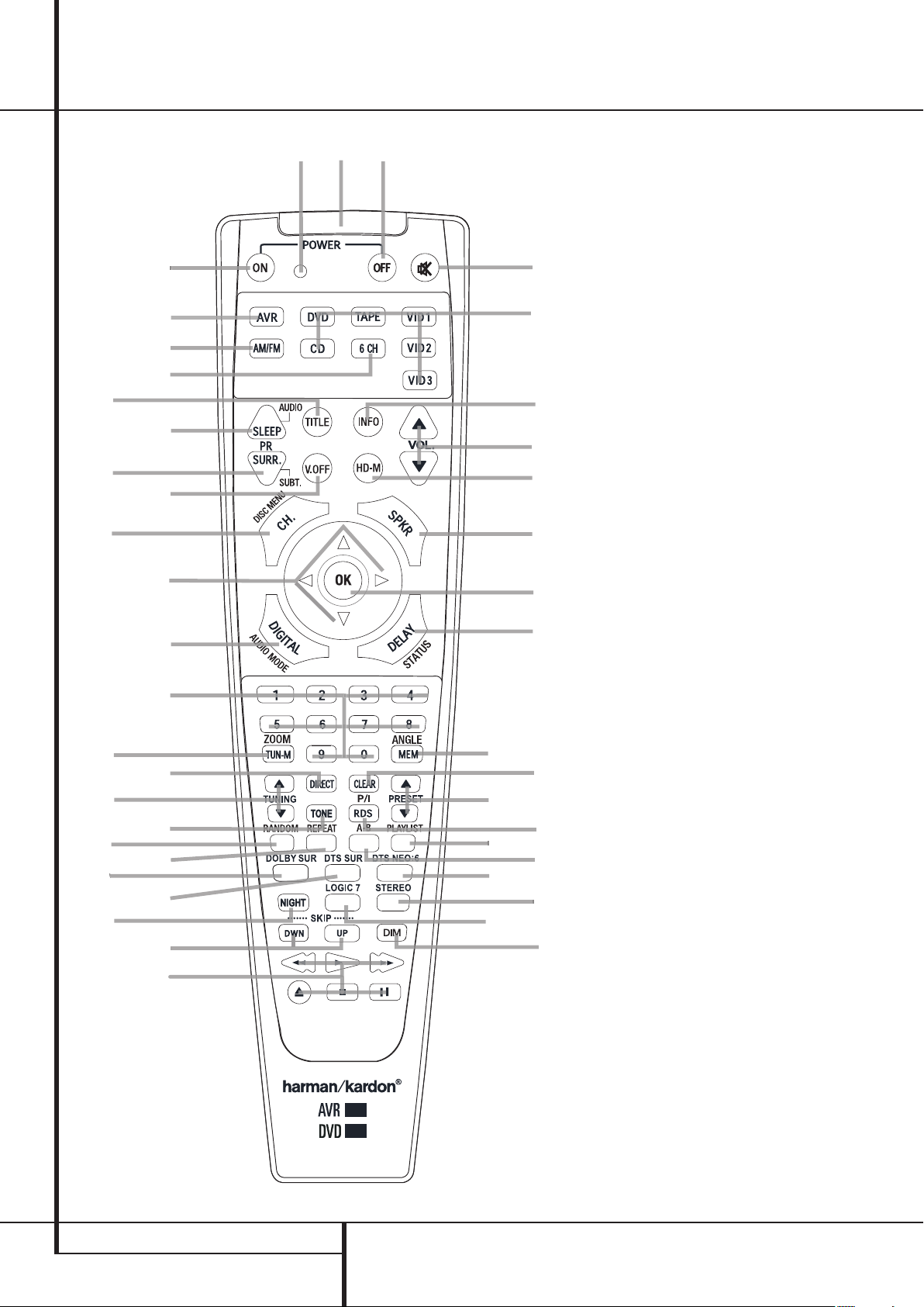
Remote Control Functions, common for AVR 138 and DVD 28
0
Power On Button
1
Not active
2
IR Transmitter Window
3
Power Off Button
4
Mute
5
Input Selectors
6
Info
7
Volume Up/Down
8
HD Mode Selector
9
Speaker Select/Setup
A
OK Button
B
Delay/Status Button
C
Memory/Angle Button
D
Clear Button
E
Preset Up/Down
F
RDS Select/Progressive Scan/Interlaced
Button
G
Playlist
H
A-B
I
DTS Neo:6 Mode Selector
J
Stereo Mode Selector
K
Logic 7 Selector
L
Dim Button
M
Transport Buttons
N
Skip Up/Down Buttons (DWN)/(UP)
O
Night Mode
P
DTS Digital Mode Selector
Q
Dolby Mode Selector
Repeat
Random
Tone Mode/Test Tone ON/OFF
Tuning Up/Down
Direct Button
Tuner Mode/Zoom
Numeric Keys
Digital Select/Audio Mode
Navigation Buttons
Channel Select /Disc Menu Button
V.OFF
Surround Mode Selector/Program
Down/Subtitle Button
Sleep/Program Up/Audio Select Button
Title
6-Channel Direct Input
AM/FM Tuner Select
AVR Selector
4 REMOTE CONTROL FUNCTIONS
Page 5

Remote Control Functions, common for AVR 138 and DVD 28
DTS Neo:6 MUSIC
DTS Neo:6
CINEMA
IMPORTANT NOTE: The 13828 remote has
some buttons that perform different functions. If
you press the AVR Button
, one set of functions is active, identical to the functions for buttons CD,Tape, Video 1/2/3. If you press the DVD
Button
5
, some of the buttons change their
function as indicated above the button itself, and
explained below. Refer to the function table for
an overview of functions in both modes.
0
Power On Button: Press this button to
turn on the power to the AVR or the DVD selected
by pressing either the AVR or the DVD Button
or 5.
1
This indicator is not active.
2
IR Transmitter Window: Point this window
towards the AVR when pressing buttons on the
remote to make certain that infrared commands
are properly received.
3
Power Off Button: Press this button to
place the AVR or a selected device unit in the
Standby mode. If held for more than 3 seconds,
both the AVR and the DVD switch to Standby.
4
Mute: Press this button to momentarily
silence the AVR or TV set being controlled,
depending on which device has been selected.
5
Input Selectors: Pressing one of these
buttons will perform three actions at the same
time. First, if the AVR is not turned on, this will
power up the unit. Next, it will select the source
shown on the button as the input to the AVR.
Finally, the DVD Button will switch the doublefunction remote buttons to their DVD functions.
After pressing the DVD Button, you must press
the AVR Selector button
again to operate
all the AVR’s functions with the remote. Note
that pressing the DVD Button switches on BOTH
the AVR and the DVD, whereas pressing the AVR
Button just switches on the AVR.
6
Info (DVD): Press for detailed informations
on the disc playing (Video/Audio Bit rate, Movie
aspect ratio and others), and for current player
settings made. Note that the unit doesn’t react
on any transport button as long as the info
menu is displayed. Press again to remove
information from screen.
7
Volume Up/Down: Press these buttons to
raise or lower the system volume.
8
HD Mode Selector (DVD): When the
DVD player is connected to a video display using
the HDMI Output
, the display sends information to the DVD indicating the highest video
resolution it is capable of handling, and the
DVD automatically sets the video output to
match it. Pressing this button allows you to
manually change the output resolution, with
your selection indicated by the Video Output
Indicators O.
The DVD will not allow you to select a resolution
beyond the capabilities of your display, and if
you try to do so, an on-screen error message will
appear to alert you to the selection of an incompatible video format. Changes made with this
button remain active until the DVD or the display is turned off.When either is turned off, and
then on again, the DVD will revert to the default
setting transmitted by the display.
9
Speaker Select/Setup: Press this button
to begin the process of configuring the AVR’s
Bass Management System for use with the type
of speakers used in your system. Once the button has been pressed, use the
to select the channel you wish to set up.
Press the OK button
A
K/L
buttons
and then select the
speaker type (see page 14 for more information.)
For DVD: Press this button to use the DVD’s onscreen menu system to adjust the player’s configuration settings. Note that the Info Button
6
must be pressed to access the DVD’s
Information menu to obtain detailed disc information, and to configure the playback mode of
the disc.
A
OK Button: This button is used to enter
settings into the AVR’s memory. It is also used in
the setup procedures for delay time, speaker
configuration and channel output level
adjustment.
B
Delay/Status Button: Press this button to
begin the process for setting the delay times
used by the AVR when processing surround
sound. After pressing this button, the delay
times are entered by pressing the OK button
A
and then using the
K/L
buttons to
change the setting. Press the Set button again to
complete the process. (See page 16 for more
information.)
For DVD: Press while a disc is playing to view
banner display. Use the ARROW buttons to move
through the different features in the Banner
Display.When a symbol is highlighted, press OK
on the remote to select it.
C
Memory/Angle Button: Press this button
to enter a radio station into the AVR’s preset
memory.Two underline indicators will flash at the
right side of the Main Information Display
F
, you then have five seconds to enter a preset
memory location using the Numeric Keys
(See page 23 for more information.)
For DVD: Press to access various camera angles
on a DVD (If the DVD contains multiple camera
angles) or to rotate JPEG images.
D
Clear Button: Press this button to clear
incorrect entries when using the remote to
directly enter a radio station’s frequency.
E
Preset Up/Down: When the tuner is in
use, press these buttons to scroll through the
stations programmed into the AVR’s memory.
When CD or DVD is selected using the Input
Selector button
5
, these buttons may func-
tion as Slow Fwd/Rev (DVD) or ”+10” (CD).
F
RDS Select/Progressive Scan/Interlaced
Button: Press this button to display the various
messages that are part of the RDS data system of
the AVR’s tuner. (See page 24 for more information on RDS).
For DVD: Press this button to change the resolution of the Component Video Output between
standard definition and progressive definition
(PAL interlaced and PAL progressive; NTSC interlaced and NTSC progressive).
The new setting will become effective after
quitting the Setup menu.
G
Playlist (DVD): Press this button to
change the playback order of the disc.
H
A-B (DVD): Press to select section A-B and
to play repeatedly.
I
DTS Neo:6 Mode Selector: Pressing this
selector button cycles the AVR through the
various DTS Neo:6 modes, which extract a fivechannel surround field from two-channel
program material (from PCM source or analog
input signal). The first press selects the last DTS
Neo:6 surround mode that was in use, and each
subsequent press selects the next mode in the
following order:
.
REMOTE CONTROL FUNCTIONS 5
Page 6

Remote Control Functions, common for AVR 138 and DVD 28
J
Stereo Mode Selector: Press this button
to select a stereo playback mode.When the button is pressed so that
DSP SURR OFF
appears in the Main Information DisplayF,
the AVR will operate in a bypass mode with true
fully analog, two-channel left/right stereo mode
with no surround processing or bass management as opposed to other modes where digital
processing is used. When the button is pressed
so that
SURROUND OFF appears in the
Main Information Display
F
, you may enjoy
a two-channel presentation of the sound along
with the benefits of bass management. When
the button is pressed so that
5 C H STEREO
appears, the stereo signal is routed to all five
speakers, if installed.(See page 16 for more
information on stereo playback modes).
K
Logic 7 Selector: Press this button to
select one of the available Logic 7 surround
modes. (See page 19 for the available Logic 7
options).
L
Dim Button: Press this button to activate
the Dimmer function, which reduces the brightness of the front panel display, or turn it off
entirely.The first press of the button shows the
default state, which is full brightness by
indicating
Information Display
VFD FULL in the Main
F
. Press the button
again within five seconds to reduce the
brightness by 50%, as indicated by
HALF. Press the button again within five
VFD
seconds and the main display will go completely
dark. Note that this setting is temporary; the
display will always return to full brightness when
the AVR is turned on. In addition,both the
Power Indicator
2
and the blue accent
lighting inside the volume control will always
remain at full brightness regardless of the
setting. This is to remind you that the AVR is still
turned on.
M
Transport Buttons: These buttons operate
the DVD player.
N
Skip Up/Down Buttons (DVD):
(DWN): Press to go to beginning of current
track. Press again quickly to go to beginning of
previous track. After pressing the PAUSE button,
each press of this button will move the image in
reverse frame by frame.
(UP): Press to go to beginning of next track.
After pressing the PAUSE button, each press of
this button will move the image forwards frame
by frame.
O
Night Mode: Press this button to activate
the Night mode.This mode is available only with
Dolby Digital encoded digital sources, and it
preserves dialog (center channel) intelligibilty at
low volume levels (See page 17 for more
information).
P
DTS Digital Mode Selector: When a DTS
source is in use the AVR will select the
appropriate mode automatically and no other
mode will be available. Pressing this button will
display the mode currently selected by the AVR´s
decoder, depending on the surround material
played and the speaker setting.
Q
Dolby Mode Selector: This button is used
to select one of the available Dolby Surround
processing modes. Each press of this button will
select one of the Dolby Pro Logic II modes,
Dolby 3 Stereo or Dolby Digital. Note that the
Dolby Digital mode is only available with a
digital input selected and the other modes only
as long as a Dolby Digital source is not playing.
Repeat (DVD): Each press of this button
changes the playback mode to repeat a chapter
or track or the entire disc. A repeat icon will
appear in the upper right corner of the screen
indicating the current repeat mode. If the Player
Information Screen is active, the changes will be
displayed on screen.
Random (DVD): Press for RANDOM
playback in random order.
Tone Mode: Pressing this button enables
or disables the Bass and Treble tone controls.
When the button is pressed so that the words
TONE IN appear in the Main Information
Display
F
, the settings of the Bass and
Treble controls will affect the output signals.
When the button is pressed so that the words
TONE OUT appear in the Main Information
Display
F
, the output signal will be “flat,”
without any bass or treble alteration.
Tuning Up/Down: When the tuner is in use,
these buttons will tune up or down through the
selected frequency band. If the Tuner Mode
button
has been pressed or the Band button
8
on the front panel was held pressed so that
AUTO appears in the Main Information
Display
F
, pressing either of the buttons will
cause the tuner to seek the next station with
acceptable signal strength for quality reception.
When the
Information Display
MANUAL appears in the Main
F
, pressing these
buttons will tune stations in single-step
increments. (See page 23 for more information.)
Direct Button: Press this button when the
tuner is in use to start the sequence for direct
entry of a station’s frequency. After pressing the
button simply press the proper Numeric Keys
to select a station (See page 23 for more
information on the tuner).
Tuner Mode/Zoom: Press this button
when the tuner is in use to select between automatic tuning and manual tuning. When the button is pressed so
Main Information Display
Tuning buttons
MANUAL appears in the
F
, pressing the
7will move the frequency
up or down in single-step increments.When the
FM band is in use and
Main Information Display
AUTO appears in the
F
, pressing this
button will change to monaural reception making even week stations audible. (See page 23 for
more information.)
When a DVD or VCD is playing, press this button
to zoom the picture so that it is enlarged. There
are 4 steps to the zoom function, each progressively larger. Press through each of the zoom
stages to return to a normal picture.
Numeric Keys: These buttons serve as a
ten-button numeric keypad to enter tuner preset
positions. For DVD play you may enter track
numbers directly, followed by OK to go to the
track.
Digital Select/Audio Mode: Press this
button to assign one of the digital inputs
4G
to a source. (See page 14 for more
information on using digital inputs.) Audio
Mode: When operating the DVD, press this
Button to switch between Audio Modes.
Navigation Buttons: These are multi-purpose buttons. They will be used most frequently to
select a surround mode.These buttons are also
used to increase or decrease output levels when
configuring the unit, to select speaker
configuration or to select the digital inputs.
Channel Select /Disc Menu Button: This
button is used to start the process of setting the
AVR’s output levels with an external source. Once
this button is pressed, use the
K/L
buttonsto
select the channel being adjusted, then press the
OK button
A
, followed by the
K/L
buttons
again, to change the level setting. (See page 22 for
more information.)
DVD Disc Menu: Displays the actual DVD Disc
Menu on the TV screen in play mode. When
playing discs with JPEG images, pressing this
button will access the thumbnails.
V.OFF: Press to turn off video output for
improved performance from audio-only discs.
Press again to restore video output.
6 REMOTE CONTROL FUNCTIONS
Page 7
Function List
90
min80min70min60min50min
40
min
30
min20min10min
OFF
Surround Mode Selector/Program
Down/Subtitle Button: Press this button to
begin the process of changing the surround
mode. After the button has been pressed,
K/L
use the
buttons to select the desired
surround mode. (See page 20 for more information).
When a DVD is playing, press to select a subtitle
language or to turn subtitles off.
Note: Due to the variations in how DVD discs
are authored, the subtitle languages selected
with the Subtitle Button may not accurately
reflect the actual languages available on the
disc. It is recommended that subtitles be selected using the disc’s menu.
Sleep/Program Up>/Audio Select
Button: Press this button to place the unit in
the Sleep mode.After the time shown in the
display, the AVR will automatically go into the
Standby mode. Each press of the button changes
the time until turn-off in the
following order:
Hold the button pressed for two seconds to turn
off the Sleep mode setting.
Note that this button is also used to change
channels on your TV, VCR and SAT receiver when
selected.
DVD: Press to access various audio languages on
a DVD (If the DVD contains multiple audio
streams).
Title: When a disc is playing, press to make
the player go back to the first section of the disc.
If you are playing a DVD-Audio disc that contains other formats the DVD is capable of playing, such as linear PCM or Dolby Digital 5.1,
pressing this button may enable you to switch
playback from one audio format to another.
6-Channel Direct Input: Press this button
to select the component connected to the
6-Channel Direct Input
as the audio. Note
that when you wish to use the Six Channel
Direct Input in conjunction with a video source,
you must first select the video source by pressing
one of the Input Selectors
5
. Then press this
button to choose the 6-Channel Direct Input
as the audio source.
AM/FM Tuner Select: Press this button to
select the AVR’s tuner as the listening choice.
Pressing this button when the tuner is in use will
select between the AM and FM bands.
AVR Selector: Pressing this button will
switch the remote so that it will operate the AVR’s
functions. If the AVR is in the Standby mode, it will
also turn the AVR on.
No. Button Name AVR/TAPE/CD/VID1/VID2/VID3 DVD
AUDIO DVD
1 Power On Power On Power On
2 Power Off Power Off Power Off
5 Mute Mute Mute (AVR)
44 AVR AVR Power On AVR
6 DVD DVD DVD
6 TAPE TAPE TAPE
6 VID1 VID1 VID1
43 AM/FM AM/FM AM/FM
6 CD CD CD
42 6CH 6CH 6CH
6 VID2 VID2 VID2
6 VID3 VID3 VID3
40 Sleep/ Audio Sleep Audio
41 Title Title
8 Info Info
8 Vol Up Vol Up Vol Up
39 Surr./ Subt. Surr. Subtitle
38 V.OFF V.OFF
9 HD-M HD Mode
8 Vol Down Vol Down Vol Down
37 CH. / Disc menu Channel Disc Menu
10 SPKR / Setup Speaker Setup
36 Level+/Up Level+/Up Up
36 Left < Left < Left
11 OK SET Enter
36 Right > Right > Right
36 Level-/Down Level-/Down Down
35 Digital / Audio mode Digital Audio mode
12 Delay / Status Delay Status
34 1 11
34 2 22
34 3 33
34 4 44
34 5 55
34 6 66
34 7 77
34 8 88
33 TUN-M / Zoom TUN-M Zoom
34 9 99
34 0 00
13 MEM / Angle Memory Angle
31 Tuning Up Tuning Up
32 Direct Direct
14 Clear Clear Clear
15 Preset Up Preset Up Slow Up
31 Tuning Down Tuning Down
30 Tone Tone Mode/Test Tone ON-OFF
16 RDS/ P/I RDS P/I
15 Preset Down Preset Down Slow Down
29 Random Random
28 Repeat Repeat
18 A-B A-B
17 Playlist Playlist
27 Dolby Surround Dolby Surround Dolby Surround
28 DTS Surround DTS Surround DTS Surround
19 DTS NEO:6 DTS NEO:6 DTS NEO:6
25 Night Night Night
21 Logic7 Logic7 Logic7
20 Stereo Stereo Stereo
24 Skip Down Skip Down(DVD) Prev Step
24 Skip Up Skip Up(DVD) Next Step
22 DIM Dimmer Dimmer
23 Rew(G) Rew(DVD) REW
23 Play(AB) Play(DVD) Play
23 FF(H) FF(DVD) FF
23 Open/Close Open/Close(DVD) Open/Close
23 Stop Stop(DVD) Stop
23 Pause Pause(DVD) Pause
REMOTE CONTROL FUNCTIONS 7
Page 8
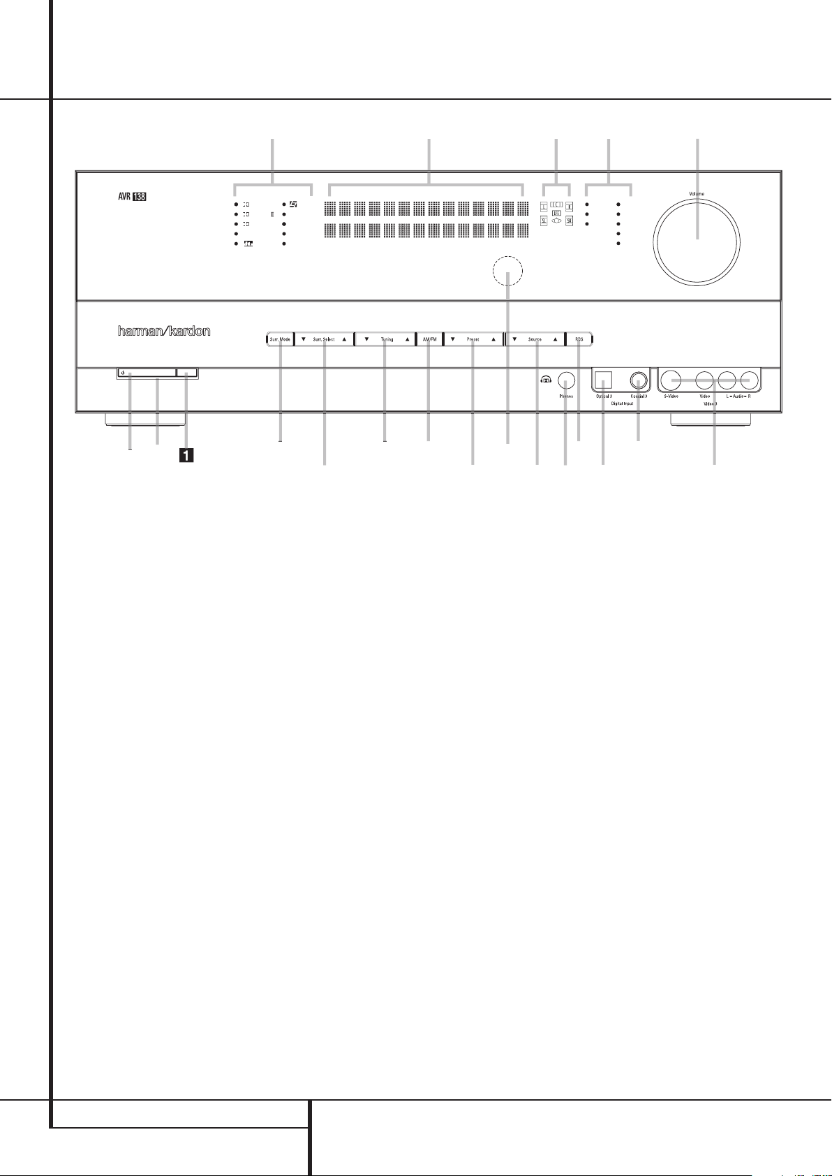
Front Panel Controls
1
67
G
9
D
F
I
J
C
8
B
H
2
4
A
5
E
3
DIGITAL LOGIC 7
VID 1 DVD
CD
FMAM
TAPE
VID 2
VID 3
PRO LOGIC
3 STEREO DSP
5 CH. STEREO
SURR. OFF
6 CH
Main Power Switch
1
System Power Control
2
Power Indicator
3
Headphone Jack
4
Digital Optical 3 Input
5
Speaker/Channel Input Indicator
6
Surround Mode Group Selector
Main Power Switch: Press this button to
apply power to the AVR. When the switch is
pressed in, the unit is placed in a Standby
mode, as indicated by the orange LED
2
. This
button MUST be pressed in to operate the unit.
To turn the unit off completely and prevent the
use of the remote control, this switch should be
pressed until it pops out from the front panel
so that the word “OFF” may be read at the top
of the switch.
NOTE: This switch is normally left in the “ON”
position.
7
Tuning
8
Tuner Band Selector
9
Preset Stations Selector
A
Input Source Selector
B
RDS Select Button
C
Surround Mode Selector
D
Surround Mode Indicators
1
System Power Control: When the Main
Power Switch
is “ON,” press this button to
turn on the AVR; press it again to turn the unit
off (to Standby). Note that the Power
Indicator
2
2
will turn blue when the unit is on.
Power Indicator: This LED will be
illuminated in orange when the unit is in the
Standby mode to signal that the unit is ready to
be turned on. When the unit is in operation, the
indicator will turn blue.
3
Headphone Jack: This jack may be used to
listen to the AVR’s output through a pair of
headphones. Be certain that the headphones
have a standard 6.3 mm stereo phone plug.
Note that the speakers will automatically be
turned off when the headphones are connected.
4
Digital Optical 3 Input: Connect the
optical digital audio output of an audio or video
product to this jack. When the Input is not in use,
be certain to keep the plastic cap installed to
avoid dust contamination that might degrade
future performance.
E
Remote Sensor Window
F
Main Information Display
G
Digital Coax 3 Input
H
Video 3 input jacks
I
Volume Control
J
Input Indicators
5
Speaker/Channel Input Indicators:
These indicators are multipurpose, indicating
either the speaker type selected for each channel
or the incoming data-signal configuration. The
left, center, right, right surround and left
surround speaker indicators are composed of
three boxes, while the subwoofer is a single box.
The center box lights when a “Small” speaker is
selected, and the two outer boxes light when
“Large” speakers are selected.When none of
the boxes are lit for the center, surround or
subwoofer channels, no speaker has been
selected for that position. (See page 16 for more
information on configuring speakers.) The letters
inside each of the center boxes display active
input channels. For standard analog inputs, only
the L and R will light, indicating a stereo input.
When a digital source is playing, the indicators
will light to display the channels begin received
at the digital input. When the letters flash, the
digital input has been interrupted. (See page 15
for more information on the Channel Indicators).
8 FRONT PANEL CONTROLS
Page 9

Front Panel Controls
6
Surround Mode Group Selector: Press
this button to select the top-level group of
surround modes. Each press of the button will
select a major mode grouping in the following
order:
Dolby Modes ➜ DTS Digital Modes ➜ DSP
Modes ➜ Stereo Modes ➜ Logic 7 Modes
Once the button is pressed so that the name of
the desired surround mode group appears in the
Lower Display Line
Mode Selector
vidual modes available. For example, press this
button to select Dolby modes, and then press
the Surround Mode Selector
from the various mode options.
7
Tuning Selector: Press the left side of the
button to tune lower frequency stations and the
right side of the button to tune higher frequency
stations.When a station with a strong signal is
reached,
MANUAL TUNED or AUTO
TUNED will appear in the Main Information
Display
F
(see page 23 for more information
on tuning stations).
8
Tuner Band Selector: Pressing this button
will automatically switch the AVR to the Tuner
mode. Pressing it again will switch between the
AM and FM frequency bands, holding it pressed
for some seconds will switch between stereo
and mono receiving and between automatic and
manual tuning mode (See page 23 for more
information on the tuner).
F
, press the Surround
C
to cycle through the indi-
C
to choose
9
Preset Stations Selector: Press this
button to scroll up or down through the list of
stations that have been entered into the preset
memory. (See page 23 for more information on
tuner programming.)
A
Input Source Selector: Press this button
to change the input by scrolling through the list
of input sources.
B
RDS Select Button: Press this button to
display the various messages that are part of the
RDS data system of the AVR’s tuner. (See page 24
for more information on RDS).
C
Surround Mode Selector: Press this button to select from among the available surround
mode options for the mode group selected. The
specific modes will vary based on the number of
speakers available, the mode group and if the
input source is digital or analog. For example,
press the Surround Mode Group Selector
6
to select a mode grouping such as Dolby or
Logic 7, and then press this button to see the
mode choices available. For more information on
mode selection, see page 9.
D
Surround Mode Indicators: Indicator will
illuminate in front of the surround mode that is
currently in use.
E
Remote Sensor Window:The sensor
behind this window receives infrared signals
from the remote control. Aim the remote at this
area and do not block or cover it unless an
external remote sensor is installed.
F
Main Information Display: This display
delivers messages and status indications to help
you operate the receiver.
G
Digital Coax 3 Input: This jack is normally
used for connection to the output of portable
digital audio devices, video game consoles or
other products that have a coax digital jack.
H
Video 3 Input Jacks: These audio/video
jacks may be used for temporary connection to
video games or portable audio/video products
such as camcorders and portable audio players.
I
Volume Control:Turn this knob clockwise
to increase the volume, counterclockwise to
decrease the volume. If the AVR is muted,
adjusting volume control will automatically
release the unit from the silenced condition.
J
Input indicators: Indicator will illuminate
in front of the input that is currently being used
as the source for the AVR.
ENGLISH
FRONT PANEL CONTROLS 9
Page 10
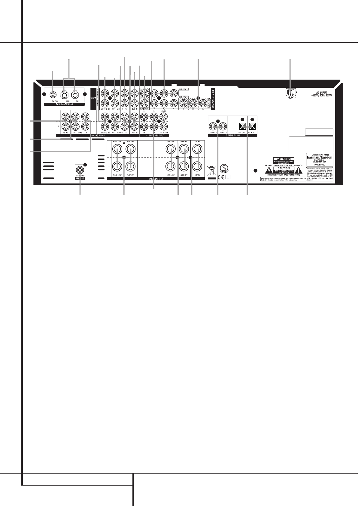
Rear Panel Connections
•
¢
°
¶
c
⁄
B
fi
‚
d
e
¡
™
b
·
‡
fl
›
‹
ª
‹
a
§
£
∞
Tape Inputs
Tape Outputs
Video 1 Audio Inputs
AM Antenna
Video 1 Audio Outputs
DVD Audio Inputs
FM Antenna
CD Inputs
Video 2 Component Video Inputs
Tape Inputs: Connect these jacks to the
PLAY/OUT jacks of an audio recorder.
Tape Outputs: Connect these jacks to the
RECORD/INPUT jacks of an audio recorder.
Video 1 Audio Inputs: Connect these jacks
to the PLAY/OUT audio jacks on a TV or other
video source.
AM Antenna: Connect the AM loop antenna
supplied with the receiver to these terminals. If an
external AM antenna is used, make connections to
the AM and GND terminals in accordance with
the instructions supplied with the antenna.
Coaxial Digital Inputs
Subwoofer Output
Video Monitor Outputs
Front/Center Speaker Outputs
Surround Speaker Outputs
Component Video Outputs
Video 1 Component Video Inputs
AC Power Cord
DVD Video Inputs
Video 1 Audio Outputs: Connect these
jacks to the RECORD/INPUT audio jacks on
a VCR or any other Audio recorder.
DVD Audio Inputs: Connect these jacks to
the analog audio jacks on a DVD or other video
source.
FM Antenna: Connect the supplied indoor or
an optional external FM antenna to this terminal.
CD Inputs: Connect these jacks to the
analog output of a compact disc player or CD
changer.
Video 1 Video Outputs
Video 2 Audio Inputs
Video 2 Video Inputs
Optical Digital Inputs
Video 1 Video Inputs
6-Channel Direct Inputs
Video 2 Component Video Inputs:
Connect the Y/Pr/Pb component video outputs of
an HDTV Set-top convertor, satellite receiver, or
other video source device with component video
outputs to these jacks.
Coaxial Digital Inputs: Connect the coax
digital output from a DVD player, HDTV receiver,
LD player, MD player or CD player to these jacks.
The signal may be either a Dolby Digital signal,
DTS signal or a standard PCM digital source.
Do not connect the RF digital output of an LD
player to these jacks.
the line-level input of a powered subwoofer. If
an external subwoofer amplifier is used, connect
this jack to the subwoofer amplifier input.
Subwoofer Output: Connect this jack to
10 REAR PANEL CONNECTIONS
Page 11

Rear Panel Connections
Video Monitor Outputs: Connect these
jacks to the composite and/or S-Video input of a
TV monitor or video projector to view the output
of any video source selected by the receiver’s
video switcher.
Front/Center Speaker Outputs: Connect
these outputs to the matching + or – terminals
on your front/center speakers.When making
speaker connections, always make certain to
maintain correct polarity by connecting the red
(+) terminals on the AVR to the red (+) terminals
on the speaker and the black (–) terminals on
the AVR to the black (–) terminals on the
speakers. (See page 12 for more information on
speaker polarity.)
Surround Speaker Outputs: Connect
these outputs to the matching + or – terminals
on your left and right surround speakers.When
making speaker connections always make certain to maintain correct polarity by connecting
the red (+) terminals on the AVR to the red (+)
terminals on the speakers and the black (–)
terminals on the AVR to the black (–) terminals
on the speakers. See page 12 for more
information on speaker polarity.
Monitor Component Video Outputs:
Connect these outputs to the component video
inputs of a video projector or monitor. When a
source connected to one of the two
Component Video Inputs
the signal will be sent to these jacks.
is selected
Video 1 Component Video Inputs:
Connect the Y/Pr/Pb component video outputs of
a DVD player to these jacks.
Note: All component inputs/outputs can be
used for RGB signals too, in the same way as
described for the Y/Pr/Pb signals, then connected
to the jacks with the corresponding color.
RGB connection is not possible if the source
outputs a separate sync signal (see page 13).
AC Power Cord: Connect the AC plug to an
unswitched AC wall output.
DVD Video Inputs: Connect these jacks to
the composite or S-Video output jacks on a DVD
player or other video source.
Video 1 Video Outputs: Connect these
jacks to the RECORD/INPUT composite or
S-Video jack on a VCR.
Video 2 Audio Inputs: Connect these jacks
to the PLAY/OUT audio jacks on a VCR or other
video source.
Video 2 Video Inputs: Connect these jacks
to the PLAY/OUT composite or S-Video jacks on
a second VCR or other video source.
Optical Digital Inputs: Connect the optical
digital output from a DVD player, HDTV receiver,
LD player, MD player or CD player to these jacks.
The signal may be either a Dolby Digital signal, a
DTS signal or a standard PCM digital source.
Video 1 Video Inputs: Connect these jacks
to the PLAY/OUT composite or S-Video jacks on
a TV or other video source.
Note: Either the Video or S-Video output of any
S-Video source must be connected to the
AVR, not both in parallel, otherwise the video
may be disturbed or its performance be
adversely effected.
6-Channel Direct Inputs: These jacks are
used for connection to source devices such as
DVD-Audio or SACD players with discrete analog
outputs.
ENGLISH
REAR PANEL CONNECTIONS 11
Page 12
Installation and Connections
After unpacking the unit, and placing it on a solid
surface capable of supporting its weight, you will
need to make the connections to your audio and
video equipment.
Audio Equipment Connections
We recommend that you use high-quality
interconnect cables when making connections to
source equipment and recorders to preserve the
integrity of the signals.
When making connections to audio source
equipment or speakers it is always a good
practice to unplug the unit from the AC wall
outlet. This prevents any possibility of
accidentally sending audio or transient signals to
the speakers that may damage them.
Important Note : In order to clearly identify all
connectors and simplify nstallation, as per the
new EIA/CEA-863 standard, all connections are
colour coded as follows:
For Speakers and Audio In/Outputs: White (Left,
speakers front) and Red (Right, speakers front).
For Speakers: Green (Center), Blue (Left
Surround) and Grey (Right Surround).
For Audio Output: Purple (Subwoofer).
For Composite Video In/Outputs: Yellow.
For Digital Audio In/Outputs: Orange.
1. Connect the analog output of a CD player to
the CD inputs
NOTE: When the CD player has both fixed and
variable audio outputs it is best to use the fixed
output unless you find that the input to the
receiver is so low that the sound is noisy, or so
high that the signal is distorted.
2. Connect the analog Play/Out jacks of a
cassette deck, MD, CD-R or other audio recorder
to the Tape Input jacks
Record/In jacks on the recorder to the Tape
Output jacks
3. Connect the output of any digital sources to
the appropriate input connections on the AVR
rear panel. Note that the Optical and Coaxial
digital inputs
Dolby Digital or DTS source or the output of a
conventional CD, MD or LD player’s PCM
(S/P-DIF) output.
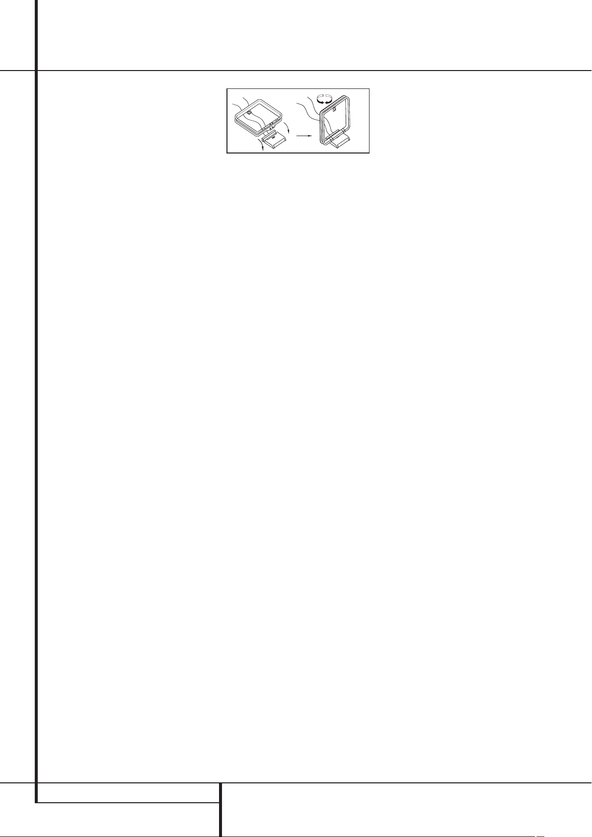
4. Assemble the AM Loop Antenna supplied with
the unit as shown below. Connect it to the AM
and GND screw terminals
.
on the AVR.
4G
. Connect the analog
may be used with a
.
5. Connect the supplied FM antenna to the FM
(75 ohm) connection
. The FM antenna may
be an external roof antenna, an inside powered
or wire lead antenna or a connection from a
cable system. Note that if the antenna or
connection uses 300-ohm twin-lead cable, you
must use a 300-ohm-to-75-ohm adapter to
make the connection.
6. Connect the front, center and surround
speaker outputs
to the respective
speakers.
To assure that all the audio signals are carried to
your speakers without loss of clarity or
resolution, we suggest that you use high-quality
speaker cable. Many brands of cable are
available and the choice of cable may be
influenced by the distance between your
speakers and the receiver, the type of speakers
you use, personal preferences and other factors.
Your dealer or installer is a valuable resource to
consult in selecting the proper cable.
Regardless of the brand of cable selected, we
recommend that you use a cable constructed of
fine, multistrand copper with an area greater
than 2 mm
Cable with an area of 1.5 mm
2
.
2
may be used for
short runs of less than 4 m. We do not
recommend that you use cables with an area less
than 1mm
2
due to the power loss and
degradation in performance that will occur.
When connecting wires to the speakers, be
certain to observe proper polarity. Remember to
connect the “negative” or “black” wire to the
same terminal on both the receiver and the
speaker. Similarly, the “positive” or “red” wire
should be connected to like terminals on the
AVR and speaker.
NOTE: While most speaker manufacturers
adhere to an industry convention of using black
terminals for negative and red ones for positive,
some manufacturers may vary from this
configuration. To assure proper phase and
optimal performance, consult the identification
plate on your speaker or the speaker’s manual to
verify polarity. If you do not know the polarity of
your speaker, ask your dealer for advice before
proceeding, or consult the speaker’s
manufacturer.
We also recommend that the length of cable
used to connect speaker pairs be identical. For
example, use the same length piece of cable to
connect the front-left and front-right or
surround-left and surround-right speakers,
even if the speakers are a different distance
from the AVR.
7. Connections to a subwoofer are normally
made via a line level audio connection from the
Subwoofer Output
to the line-level input
of a subwoofer with a built-in amplifier. When a
passive subwoofer is used, the connection first
goes to a power amplifier, which will be
connected to one or more subwoofer speakers.
If you are using a powered subwoofer that does
not have line-level input connections, follow the
instructions furnished with the speaker for
connection information.
Note: Speaker sets with two front satellites and
a passive subwoofer must be connected to the
front speaker outputs
Subwoofer Output
only rather than to the
.
8. If an external multi-channel audio source with
5.1 outputs such as an external digital
processor/decoder, DVD-Audio or SACD player is
used, connect the outputs of that device to the
6-Channel Direct Inputs
.
12 INSTALLATION AND CONNECTIONS
Page 13

Installation and Connections
Video Equipment Connections
Video equipment is connected in the same manner as audio components.Again, the use of highquality interconnect cables is recommended to
preserve signal quality.To ensure best video
performance S-Video sources should be
connected to the AVR only with their S-Video
In/Outputs, not with their composite video
connectors too.
1. Connect a VCR’s audio and video Play/Out
jacks to the Video 2 In jacks
panel. The Audio and Video Record/In jacks on
the VCR should be connected to the Video 1
Out jacks
2. Although any video device may be connected
to these jacks, we recommend connecting your
TV to the Video 1 Audio/Video Input Jacks
fact that the remote control is preprogrammed
with TV product codes for the Video 1 device.
For the same reason, we recommend connecting
your video recorder, cable TV converter or satellite receiver to the Video 2 Audio/Video
Input Jacks
3. Connect the analog audio and video outputs
of a DVD to the DVD jacks
4. Connect the digital audio outputs of a CD,
MD or DVD player, satellite receiver, cable box or
HDTV converter to the appropriate Optical or
Coaxial Digital Inputs
Remember that the DVD source defaults to the
Coaxial 1 Digital Input
default to their analog inputs, although any
source may be assigned to any digital audio
input on the receiver.
5. Connect the Composite and S-Video
(if S-Video device is in use) Monitor Output
jacks on the receiver to the composite and
S-Video input of your television monitor or video
projector.
6. If your DVD player and monitor both have
component video connections, connect the
component outputs of the DVD player to the
Video 1 Component Video Inputs
that even when component video connections
are used the audio connections must still be
made to either the analog DVD Audio Inputs
Input jacks
on the AVR.
so that you may take advantage of the
.
or any of the Coaxial or Optical Digital
.
on the rear
.
4G
.
. All other sources
. Note
7. If another component video device is available, connect it to the Video 2 Component
Video Input jacks
for this device should be made to either the
Video 2 Input jacks
or Optical Digital Input jacks
8. If the component video inputs are used,
connect the Component Video Output
the component video inputs of your TV, projector
or display device.
9. If you have a camcorder, video game or other
audio/video device that is connected to the AVR
on a temporary, rather than permanent basis,
connect the audio, video and digital audio outputs of that device to the Front Panel Inputs
4GH
jacks
connected to the digital jacks
selected as "Optical 3" or "Coaxial 3" input.
(See page 16 for more information on input
configuration.)
Video Connection Notes:
• Y/Pr/Pb Component, RGB (see page 14), or
• All component inputs/outputs can be used for
. A device connected to the Video 3
H
is selected as the Video 3 input, and
Composite video signals may only be viewed
in their native formats and will not be converted to the other formats.
RGB signals too, in the same way as described
for the Y/Pr/Pb signals, then connected to the
jacks with the corresponding color.
But this is only correct as long as only the
three RGB video signals are output by the
video source, with a sync signal in the "G"
signal only, without any sync signal output
separately by the source.
. The audio connections
or any of the Coaxial
4G
.
it is
ENGLISH
to
INSTALLATION AND CONNECTIONS 13
Page 14
System Configuration
Pb
Once the speakers have been placed in the
room and connected, the remaining steps are to
program the system configuration memories.
With the AVR two kind of memories are used,
those associated individually with the input
selected, e.g. surround modes, and others
working independently from any input selected
like speaker output levels, or delay times used
by the surround sound processor.
First Turn On
You are now ready to power up the AVR to
begin these final adjustments.
1. Plug the Power Cable
switched AC outlet.
2. Press the Main Power Switch
latches and the word “OFF” on the top of the
switch disappears inside the front panel. Note
that the Power Indicator
indicating that the unit is in the Standby mode.
3. Remove the protective plastic film from the
front-panel lens. If left in place, the film may
affect the performance of your remote control.
4. Install the three supplied AAA batteries in the
remote as shown. Be certain to follow the (+)
and (–) polarity indicators that are on the
bottom of the battery compartment.
5. Turn the AVR on either by pressing the
System Power Control
Source Selector
the remote by pressing the AVR Selector
or any of the Input Selectors5on the
remote.The Power Indicator
to confirm that the unit is on, and the Main
Information Display
NOTE: After pressing one of the Input Selector
buttons
5
to turn the unit on, press the AVR
Selector
functions.
to have the remote control the AVR
into an un-
2
will turn orange,
1
or the Input
A
on the front panel, or via
2
will turn blue
F
will also light up.
in until it
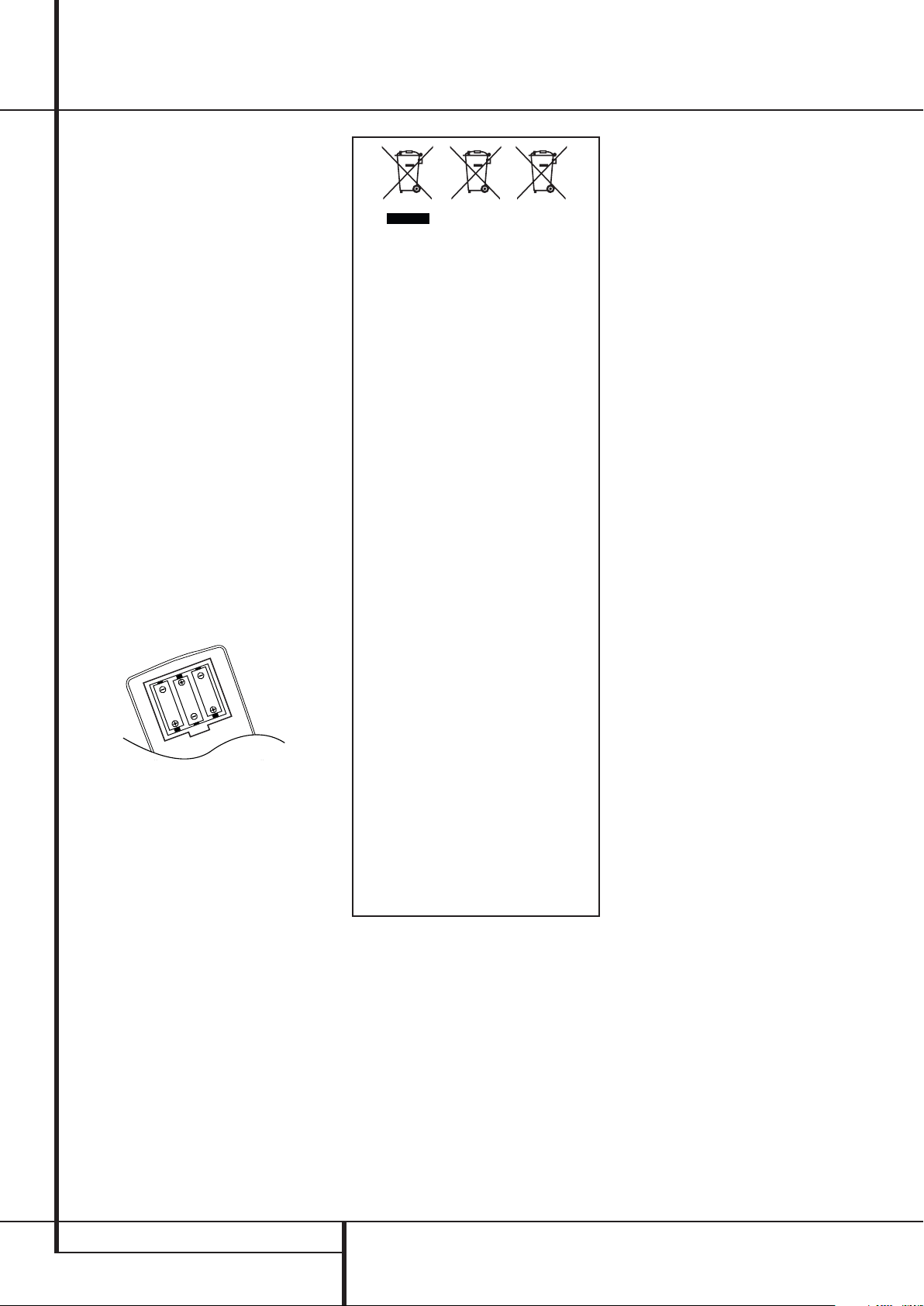
Instructions for users on removal and disposal
of used batteries.
Specification of included battery types.
These symbols shown on the product, the
packaging or in the manual or separate information sheet mean that the product itself, as
well as the batteries included or built into the
product, should never be thrown away with
general household waste.Take them to applicable collection points, where proper treatment, recycling and recovery takes place, in
accordance with national or local legislation,
or European Directives 2002/96/EC and
2006/66/EC.
Correct handling of the product and batteries
to be disposed helps saving resources and
prevents possible negative effects on the
environment or human health.
The batteries included with your equipment
may be Alkaline, Carbon Zink/Manganese or
Lithium (button cells) type.All types should
be disposed of according to the above
instructions.
To remove the batteries from your equipment
or remote control, reverse the procedure
described for inserting batteries in the
Owners Manual.
For products with a built-in battery that lasts
for the lifetime of the product, removal may
not be possible for the user. In this case, recycling or recovery centers handle the dismantling of the product and the removal of the
battery. If, for any reason, it becomes necessary to replace such a battery, this procedure
must be performed by authorized service centers.
Settings to be Made With Each
Input Used
The AVR features an advanced memory system
that enables you to establish different settings
for the speaker configuration, digital input, surround mode, delay times and output levels for
each input source.This flexibility enables you to
custom tailor the way in which you listen to each
source and have the AVR memorize them. This
means, for example, that you may associate
different surround modes and analog or digital
inputs with different sources, or set different
speaker configurations with the resultant
changes to the bass management system or the
use of the Center speaker. Once these settings
are made, they will automatically be recalled
whenever you select an input.
The default settings for the AVR, as it is shipped
from the factory, have all inputs set for an
analog source (except for the DVD input, which
has the Coaxial Digital Input 1
default), with Logic 7 Music as the surround
mode, all speaker positions set to "small", and a
subwoofer connected. Before using the unit, you
will probably want to change these settings for
most inputs so that they are properly configured
to reflect the use of digital or analog inputs, the
type of speakers installed and the surround
mode associated with the input.
Input Setup
The first step in configuring the AVR is to select
an input. This may be done by pressing the front
panel Input Source Selector
desired input’s name appears in the Main
Information Display
illuminate next to the input’s name in the front
panel Input Indicators
be selected by pressing the appropriate Input
Selector on the remote control
The second step is to associate one of the digital
inputs with the selected input source (if this is
needed, otherwise the selected analog input will
remain). Press the Digital Input Select button
on the remote.Within five seconds, make
your input selection using the
on the remote until the desired digital or
analog input is shown in the Main Informa-
tion Display
A
to enter the new digital input assignment.
After the setting has been made with one input,
repeat as described above with all inputs in use.
The digital input associated with the input
selected can also be changed at any time later
and the AVR’s memory system will keep the settings until they are changed again.
F
J
F
. Then press the OK button
as the
A
until the
, and Indicator will
. The input may also
5
.
K/L
buttons
14 SYSTEM CONFIGURATION
Page 15

System Configuration
Speaker Setup
This setup tells the AVR which type of speakers
are in use.This is important as it adjusts the
settings that determine which speakers receive
low frequency (bass) information and whether a
Center speaker should be used or not, separately
for each input used. For each of these settings
use the
LARGE setting if the speakers for a
particular position are traditional full-range
loudspeakers that are capable of reproducing
sounds below 100Hz. Use the
SMALL setting
for smaller, frequency-limited satellite speakers
that do not reproduce sounds below 100Hz.
Note that when “small” front (left and right)
speakers are used, a subwoofer is required to
reproduce low frequency sounds. If you are in
doubt as to which category describes your
speakers, consult the specifications in the
speakers’ owner’s manual, or ask your dealer.
With the AVR turned on, follow these steps to
configure the speakers:
1. Press the Speaker button
remote.The words
FRONT SPEAKER will
appear in the Main Information Display
2. Press the OK button
3. Press the
to select
SMALL, matching the type of speakers you
K/L
buttons on the remote
FRONT LARGE or FRONT
A
9
on the
F
.
have at the left-front and right-front positions,
as described by the definitions shown in preceding section.
When
SMALL is selected, low frequency front
channel sounds will be sent only to the subwoofer
output. Note that if you choose this option and
there is no subwoofer connected, you will not
hear any low frequency sounds from the front
channels.This setting is not available with stereo
mode to ensure purest sound by bypassing the
crossovers of the DSP´s.
When
LARGE is selected, a full-range output
will be sent to the front left and front right outputs. Depending on the subwoofer configuration
(see below), the front left and right bass information may also be directed to a subwoofer.
Important Note: When a speaker set with two
front satellites and a passive subwoofer is used,
connected to the front speaker outputs
the fronts must be set for
LARGE.
,
4. When you have completed your selection for the
front channels, press the OK button
then press the
to change the display to
SPEAKER.
K/L
buttons on the remote
CENTER
A
, and
A
5. Press the OK button
K/L
buttons on the remote to select the
again, and use the
option that best describes your system based on
the Center speaker definitions shown in preceding section.
When
SMALL is selected, low frequency center
channel sounds will be sent to the Fronts, if they
are set for
LARGE and Sub is turned off. When
Sub is on, low frequency center channel sounds
will be sent to the subwoofer only.
When
LARGE is selected, a full-range output
will be sent to the center speaker output, and
with analog and digital surround modes (except
with the Pro Logic II Music mode) NO center
channel signal will be sent to the subwoofer
output.
When
NONE is selected, no signal will be sent
to the center channel output. The receiver will
operate in a “phantom” center channel mode
and center channel information will be sent to
the left and right front channel outputs and its
bass will be sent to the subwoofer output too as
long as SUB L/R+LFE is selected in the SUB-
.
WOOFER line in this menu (see below). This
mode is needed if no Center speaker is used.
Note that for the use of Logic 7C surround mode
a Center speaker is needed, but Logic 7M works
well without a Center too.
6. When you have completed your selection for
the center channel, press the OK button
and then press the
remote to change the display to
SPEAKER.
7. Press the OK button
K/L
the
K/L
buttons on the
SURR
A
again, and then use
buttons on the remote to select
the option that best describes your system based
on the Surround speaker definitions shown in
preceding section.
When
SMALL is selected, with all digital sur-
round modes low frequency surround channel
sounds will be sent to the Fronts, when Sub is
turned off, or to the subwoofer output when Sub
is on. With the analog surround modes the rear
bass feed depends on the mode selected and
the setting of the sub and front speakers.
When
LARGE is selected, a full-range output
will be sent to the surround channel outputs
(with all analog and digital surround modes),
and, except with Hall and Theater modes, NO
surround channel bass will be sent to the
subwoofer output.
A
When
NONE is selected, surround sound
information will be split between the front-left
and front-right outputs. Note that for optimal
performance when no surround speakers are in
use, the Dolby 3 Stereo mode should be used
instead of Dolby Pro Logic.
8. When you have completed your selection for
the surround channel, press the OK button
and then press the
K/L
buttons on
the remote to change the display to
S-W SPEAKER.
9. Press the OK button
K/L
buttons on the remote to select the
A
, and then press the
option that best describes your Subwoofer system.
The choices available for the subwoofer position
will depend on the settings for the other
speakers, particularly the front left/right
positions.
If the front left/right speakers are set to
SMALL, the subwoofer will automatically be
set to
SUB, which is the “on” position.
If the front left/right speakers are set to
LARGE, three options are available:
• If no subwoofer is connected to the AVR, press
the arrow buttons
so that SUB NONE
appears in the display.When this option is
selected, all bass information will be routed to
,
the front left/right “main” speakers.
• If a subwoofer is connected to the AVR, you
have the option to have the front left/right
“main” speakers reproduce bass frequencies at
all times, and have the subwoofer operate only
when the AVR is being used with a digital source
that contains a dedicated Low Frequency Effects,
or LFE soundtrack. This allows you to use both
your main and subwoofer speakers to take
advantage of the special bass created for certain
movies.To select that option press the arrow
buttons
so that SUB LFE appears in the
display.
• If a subwoofer is connected and you wish to
use it for bass reproduction in conjunction with
the main front left/right speakers, regardless of
the type of program source or surround mode
you are listening to, press the arrow buttons
so that SUB L/R+LFE appears in the
display.When this option is selected, a “complete” feed will be sent to the front left/right
“main” speakers, and the subwoofer will receive
the front left and right bass frequencies under
the crossover frequency 80 Hz, additionally to
the LFE soundtrack (see above).
A
ENGLISH
,
SYSTEM CONFIGURATION 15
Page 16

LR
C
SL SR
LFE
System Configuration
10. When all speaker selections have been made
for the input selected, press the OK button
twice or simply wait for three seconds until the
display returns to the normal mode.
To assist in making these settings, the icons in
the Speaker/Channel Input Indicators
will change as the speaker type is selected at
each position. When only the inner icon box is
lit, the speaker is set for “small.” When the inner
box and the two outer boxes with circles inside
them are lit, the speaker is set for “large." When
no indicator appears at a speaker location, that
position is set for “none” or “no” speaker.
As an example, in the Figure below, the left front
and right front speakers are set for “large,” the
center, left surround and right surround speakers
are set for small, and a subwoofer is set.
Surround Setup
Once the speaker setup has been completed, the
next setup step is to set the surround mode you
wish to use with each input. Since surround
modes are a matter of personal taste, feel free to
select any mode you wish – you may change it
later. To make it easier to establish the initial
parameters for the AVR, it is best to leave the
default setting of Logic 7 Music mode for most
analog inputs and Dolby Digital for inputs connected to digital sources. In the case of inputs
such as a CD Player, Tape Deck or Tuner, you may
wish to set the mode to Stereo, if that is your
preferred listening mode for standard stereo
sources, where it is unlikely that sur
ed material will be used.
To set the surround mode you wish to use with
the input selected, press the Surround Mode
Selector button
the remote until the desired surround mode´s
name appears in the Main Information
Display
As the modes are changed, Indicator will
illuminate next to the mode names in the
Surround Mode Indicators
panel.
F
.
6
on the front or
D
A
5
round encod-
on the front
on
Note that Dolby Digital and DTS will only appear
as choices when a digital input has been
selected.
After the surround mode setting has been made
with the current input, repeat the setting with all
inputs you will use.The surround mode can also
be changed at any time later, and the AVR’s
memory system will keep the settings for the
input selected, until they are changed again.
Configuring the Surround Off
(Stereo) Modes
For superior reproduction of two-channel
program materials, the AVR offers two Stereo
modes: an analog Stereo-Direct mode that
bypasses the digital signal processing circuitry
for a completely analog signal path that preserves the purity of the original signal, and a
digital mode that is capable of providing bass
management for optimal distribution of the low
frequencies between smaller speakers and a
subwoofer.
Stereo-Direct (Bypass) Mode
When the analog Stereo-Direct mode is selected
by pressing the Stereo Mode Selector
until SURROUND OFF appears in the Main
Information Display
Mode Indicator
AVR will pass the analog source material directly
through to the front left and right speakers,
bypassing the digital processing circuitry.
In this mode, the front left and right speakers
will automatically be configured as
is not possible to configure these speakers as
SMALL.
When the AVR is in the Stereo Bypass mode you
may still configure the subwoofer output so that
it is either turned off, with a full-range signal
going to the front left/right speakers, or you may
configure it so that the subwoofer feed is
activated. The factory default setting is to have
the subwoofer turned off for this mode, but you
may change that setting by following these
steps:
1. Press the Speaker Button
2. Press the OK Button
configuration menu.
3. Press the
to select the desired option.
off the feed to the subwoofer, while
<L+R> turns it on.
4. When the desired setting has been entered,
press the OK Button
operation.
K/L
F
and the Surround
D
for Surround Off is lit, the
9
A
to activate the
Buttonson the remote
SUB NONE turns
A
to return to normal
J
LARGE;it
.
SUB
Stereo-Digital Mode
When the Stereo-Direct (Bypass) mode is in use
a full range signal is always sent to the front
left/right speakers. By its nature, that option
does not pass the signal through the AVR’s digital signal processing, creating the requirement
for full-range speakers. If your front speakers are
bandwidth limited, “satellite”speakers, we
recommend that you do NOT use the Bypass
mode, but rather use the
OFF mode for stereo listening.
To listen to programs in the two-channel stereo
mode while taking advantage of the bass
management system, press the Stereo Mode
Selector
appears in the Main Information Display
and the DSP and SURR. OFF Surround
Mode Indicators
the
Indicators
(Bypass) mode.
When this mode is in use, the front left/right
speakers and subwoofer may be configured to
meet the requirements of your specific speakers
using the steps shown in the Speaker Setup
section.
Delay Settings
Only for the Dolby or DTS modes, you will need
to adjust the delay time setting. Note that the
delay time is not adjustable for any other modes.
Due to the different distances between the
listening position for the front channel speakers
and the surround speakers, the amount of time it
takes for sound to reach your ears from the front
or surround speakers is different.You may
compensate for this difference through the use
of the delay settings to adjust the timing for the
specific speaker placement and acoustic
conditions in your listening room or home
theater.
The factory setting is appropriate for most
rooms, but some installations create an uncommon distance between the front and surround
speakers that may cause the arrival of front
channel sounds to become disconnected from
surround channel sounds.
J
until SURROUND OFF
SURR. OFF Surround Mode
D
is lit you are in the Stereo-Direct
DSP SURROUND
D
both light up.When only
F
16 SYSTEM CONFIGURATION
Page 17

System Configuration
To resynchronize the front, center and surround
channels, follow these steps:
1. Measure the distance from the listening/
viewing position to the front speakers in
meters.
2. Measure the distance from the listening/
viewing position to the surround speakers.
3. Press the Delay Button
4. When
FRONT L DELAY appears in the
Main Information Display
Button
A
.
5. Press the
K/L
B
.
F
press the OK
Buttonson the remote
to enter the distance from the front left/right
speakers to your listening position. Press the OK
Button
A
when this is complete.
6. Press the
so that
Main Information Display
OK Button
you will see
7. Press the the
K/L
Buttonson the remote
CENTER DELAY appears in the
F
and press the
A
(After CENTER DELAY,
FRONT R DELAY).
K/L
Buttonson the
remote to enter the distance from the center
speaker your listening position. Press the OK
Button
A
when this is complete.
8. Press the
so that
SURR DELAY L appears in the Lower
Display Line and press the OK Button
9. Press the the
K/L
Buttonson the remote
SURR DELAY R and after that
A
K/L
Buttonson the
.
remote to enter the distance from the surround
speakers to your listening position. Press the
OK Button
A
when this is complete.
10. When all adjustments have been made, the
unit will return to normal operation in five
seconds.
Night Mode Settings
The Night mode is a feature of Dolby Digital that
uses special processing to preserve the dynamic
range and full intelligibility of a movie sound
track while reducing the peak level. This prevents
abruptly loud transitions from disturbing others,
without reducing the sonic impact of a digital
source. Note that the Night mode is only
available when the Dolby Digital surround mode
is selected.
To adjust the Night mode setting press the
Input Source Selector
A
on the front or
5
on the remote and select an input that is associated with a digital input and the Dolby Digital
surround mode.
Next press the Night button
O
on the remote.
When the button is pressed, the words
D-RANGE (Dynamic Range) followed by the
current setting (MID, MAX, OFF) will appear in
the Main Information Display
K/L
buttons within five seconds to select
F
. Press the
the desired setting:
OFF: When OFF is shown in the display, the
Night mode will not function.
MID: When MID is shown in the display, a
mild compression will be applied.
M
AX: When MAX is shown in the display, a
more severe compression algorithm will be
applied.
When you want to use the Night mode feature,
we recommend that you select the MID setting
as a starting point and change to the MAX
setting later, if desired.
Output Level Adjustment
Output level adjustment is a key part of the
configuration process for any surround sound
product. It is particularly important for a Dolby
Digital receiver such as the AVR, as correct
outputs will ensure that you hear sound tracks
with the proper directionality and intensity.
NOTE: Listeners are often confused about the
operation of the surround channels.While some
assume that sound should always be coming
from each speaker, most of the time there will
be little or no sound in the surround channels.
This is because they are only used when a
movie director or sound mixer specifically places
sound there to create ambiance, a special effect
or to continue action from the front of the room
to the rear. When the output levels are properly
set it is normal for surround speakers to operate only occasionally.Artificially increasing the
volume to the rear speakers may destroy the
illusion of an enveloping sound field that
duplicates the way you hear sound in a movie
theater or concert hall.
IMPORTANT NOTE: The output level can be
adjusted for each digital and analog surround
mode separately.This allows you to compensate
for level differences between speakers, that may
also vary with the surround mode selected, or to
increase or decrease the level of certain speakers
intentionally, depending on the surround mode
selected. Note that adjustments made for any
surround mode are effective with all inputs
associated with that surround mode.
Before beginning the output level adjustment
process, make certain that all speaker
connections have been properly made.The
system volume should be turned down at first.
For the easiest set-up, follow these steps while
seated in the listening position that will be used
most often:
1. Make certain that all speaker positions have
been properly configured for their “large” or
“small” settings (as outlined above) and turn
off the OSD system if it is in use.
2. Adjust the volume so that it is at
-15,as
shown in the on-screen display or Main
Information Display
F
.
To adjust and calibrate the output levels, follow
these steps. For accurate calibration, it is a good
idea to make these adjustments while seated in
your favorite listening position. As the adjustment must be made for each surround mode, it
is best to select any input associated with any
Dolby Pro Logic II mode, make the adjustment
for that surround mode, then step through all
inputs you´re using (and thus through all surround modes associated with the inputs) and
repeat the adjustment when any surround mode
appears that has not yet been adjusted.
1. Select any input associated with any Dolby
Pro Logic II surround mode by pressing the
Input Source Selector
Logic II Surround Mode Indicator
A5until the Pro
D
on
the frontdisplay lights up.
2. Press and hold the Tone button
on the
remote for more than 3 seconds.The words
T-TFL0DBwill appear in the Main
Information Display
F
.
3. The test noise will immediately begin to
circulate in the speakers in a clockwise rotation,
pausing at each position for two seconds.As the
test noise rotates the speaker positions
FR, SR, SL(Front Left, Center, Front Right,
FL, C,
Surround Right, Surround Left) will be shown in
the Main Information Display
F
. As an
added assist, while the test noise is circulating,
the proper channel position will also be indicated in the Speaker/Channel Indicators
5
by
a blinking letter within the correct channel. Turn
up the volume now until you can hear the noise
clearly.
ENGLISH
SYSTEM CONFIGURATION 17
Page 18

System Configuration
IMPORTANT NOTE: Because this test noise will
have a much lower level than normal music, the
volume must be lowered after the adjustment
for all channels is made, BEFORE you turn the
test tone off.
NOTE: This is a good time to verify that the
speakers have been properly connected.As the
test noise circulates, listen to make certain that
the sound comes from the speaker position
shown in the Main Information Display. If the
sound from a speaker location does NOT match
the position indicated in the display, turn the
AVR off using the Main Power Switch
and
check the speaker wiring to make certain that
each speaker is connected to the correct output
terminal.
After checking for speaker placement, let the
test noise circulate again, and listen to see
which channels sound louder than the others.
Using the front left speaker as a reference, press
K/L
the
buttons on the remote to bring
all speakers to the same volume level. Note that
when one of the
K/L
buttons is pushed, the
test noise circulation will pause on the channel
being adjusted to give you time to make the
adjustment. When you release the button, the
circulation will resume after five seconds.
Continue to adjust the individual speakers until
they all have the same volume. Note that
adjustments should be made with the
K/L
buttons on the remote only, NOT the main
volume controls.
When all channels have the same output level,
turn the Volume
I7down to about –40dB,
otherwise the listening level may be too high as
soon as the source’s music starts to play.
Afterwards press the Tone Button
button
again to turn the test tone off and complete the
process.
IMPORTANT NOTE: The Output level
adjustment made will be effective for the
surround mode currently selected, also when
other inputs are selected using the same
surround mode.To adjust the output level with
all other surround modes used, step through all
inputs you´re using by pressing the Source
Selector buttons
appropriate Input Selectors
A
on the front panel or the
5
on the remote.
When the indicator for any surround mode for
which the level adjustment has not yet been
made lights in the Main Information Display
F
or its Indicator will illuminate in the
Surround Mode Indicators field
D
, repeat
the level adjustment described above.This will
also allow you to compensate level differences
between speakers, that may be different with
each surround mode, or to increase or decrease
the level of certain speakers intentionally,
depending on the surround mode selected.
Once the settings outlined on the previous
pages have been made, the AVR is ready for
operation. While there are some additional
settings to be made, these are best done after
you have had an opportunity to listen to a
variety of sources and different kinds of program
material. These advanced settings are described
on page 21 of this manual. In addition, any of
the settings made in the initial configuration of
the unit may be changed at any time.
As you add new or different sources or speakers,
or if you wish to change a setting to better
reflect your listening taste, simply follow the
instructions for changing the settings for that
parameter as shown above. Note that any
settings changed at any time, will be stored in
memory in the AVR, also if it´s turned off
completely, unless it will be reset (see page 34).
Having completed the setup and configuration
process for your AVR, you are about to
experience the finest in music and home theater
listening. Enjoy!
18 SYSTEM CONFIGURATION
Page 19

Operation
90
min80min70min60min50min
40
min
30
min20min10min
OFF
Basic Operation
Once you have completed the setup and
configuration of the AVR, it is simple to operate
and enjoy.The following instructions should be
followed for you to maximize your enjoyment of
your new receiver:
Turning the AVR On or Off
• When using the AVR for the first time, you must
press the Main Power Switch
panel to turn the unit on. This places the unit in a
Standby mode, as indicated by the orange color of
the Power Indicator
Standby, you may begin a listening session by
pressing the System Power Control
Source button
Selector
2
will turn blue.This will turn the unit on and
A
on the front panel or the AVR
. Note that the Power Indicator
return it to the input source that was last used.
The unit may also be turned on from Standby by
pressing any of the Source Selector buttons on
the remote
5
NOTE: After pressing the the DVD Button
to turn the unit on, press the AVR Selector
to have the remote control all of the AVR functions.
To turn the unit off at the end of a listening
session, simply press the System Power
Control
1
on the front panel or the Power
Off Button
3
on the remote.
When the remote is used to turn the unit “off” it
is actually placing the system in a Standby mode,
as indicated by the orange color of the Power
Indicator
2
.
When you will be away from home for an
extended period of time it is always a good idea
to completely turn the unit off with the front
panel Main Power Switch
NOTE: All preset memories may be lost if the
unit is left turned off with the Main Power
Switch
for more than two weeks.
Using the Sleep Timer
• To program the AVR for automatic turn-off,
press the Sleep Button
press of the button will increase the time before
shut down in the following sequence:
When the programmed sleep time has elapsed,
the unit will automatically turn off (to Standby
mode). Note that the front panel display will dim
to one half brightness when the Sleep function
is programmed. To cancel the Sleep function,
press and hold the Sleep Button
information display returns to normal brightness
and the
SLEEP OFF message appears in the
Main Information Display
on the front
2
. Once the unit is in
.
.
on the remote. Each
F
.
1
or the
until the
5
Source Selection
• To select a source, press any of the
Source Selector buttons on the remote
5
NOTE: After pressing the DVD Button
must press the AVR Selector
.
5
you
to have the
remote control all of the AVR functions.
• The input source may also be changed by
pressing the front-panel Input Source
Selector button
A
. Each press of the button
will move the input selection through the list of
available inputs.
• As the input is changed, the AVR will automatically switch to the digital input (if selected),
surround mode and speaker configuration that
were entered during the configuration process
for that source.
• The front-panel Video 3 Inputs
Digital 3 Input
Input
G
4
or the Coaxial Digital 3
may be used to connect a device such
H
, Optical
as a video game or camcorder to your home
entertainment system on a temporary basis.
• As the input source is changed, the new input
name will appear in the Main Information
Display
F
and a green LED will light next to
the selected input’s name in the front-panel
Input Indicators
J
.
• When a pure audio input (CD, Tuner, Tape,
6/8 Channel Input) is selected, the last video
input used remains routed to the Video Out-
puts
and Video Monitor Output.
This permits simultaneous viewing and listening
to different sources.
• When a Video source is selected, its audio
signal will be fed to the speakers and the video
signal for that input will be routed to the
appropriate Monitor Output Jack
and will
be viewable on a TV monitor connected to the
AVR. If a component video source is connected to
the Video 1
or Video 2Component
Inputs, it will be routed to the Component
Video Outputs
. Make certain that your TV is
set to the proper input to view the appropriate
video signal (composite, S-Video or component
video, see Notes for S-Video on page 13).
Controls and Use of Headphones
• Adjust the volume to a comfortable level using
the front panel Volume Control
Volume Up/Down
7
• To temporarily silence all speaker outputs
press the Mute button
4
the output to all speakers and the headphone
jack, but it will not affect any recording or
dubbing that may be in progress. Press the
Mute button
4
again to return to normal
operation.
I
or remote
buttons.
. This will interrupt
• During a listening session you may wish to
adjust the Bass Control and Treble Control
to suit your listening tastes or room acoustics.
• To set the output of the AVR so that the output is “flat,” with the Tone controls de-activated,
press the Tone Mode button
or twice so that the words
button once
Tone Out appear
momentarily in the Main Information Display
F
. To return the tone controls to an active condition, press the Tone Mode
or twice so that the words
button once
Tone In momen-
tarily appear in the Main Information Display
F
.
• To change the Bass or Treble Control settings
press the Tone Mode Button
until the
words Bass or Treble appear momentarily in the
Main Information Display
Button
A
followed by the A/BButtons
F
. Press the OK
to adjust the setting. When done, press the Tone
Mode Button
again to exit the Tone Mode
Menu.
• For private listening, plug the 6.3 mm stereo
phone plug from a pair of stereo headphones
into the front panel Headphone Jack
3
. Note
that when the headphone’s plug is connected,
the word
the Main Information Display
HEADPHONE will scroll once across
F
and all
speakers will be silenced.When the headphone
plug is removed, the audio feed to the speakers
will be restored.
• When the headphones are in use, you may
take advantage of the Dolby Headphone modes
to bring added spaciousness to headphone
listening. Press the Dolby Mode Select
Button
Q
or the Surround Mode Group
Selector
6
to cycle through the three Dolby
Headphone modes to select the one that you
prefer.
Surround Mode Selection
One of the most important features of the AVR is
its ability to reproduce a full multichannel
surround sound field from digital sources, analog
matrix surround encoded programs and standard
stereo or even mono programs. In all, a total of
fifteen listening modes are available on the AVR.
Selection of a surround mode is based on
personal taste, as well as the type of program
source material being used.
For example, motion pictures, CD’s or TV
programs bearing the logo of one of the major
surround encoding processes, such as Dolby
Surround should be played in either the Dolby
Pro Logic II Movie (with movies) or Music (with
music) surround mode or with the
Harman Kardon´s exclusive Logic 7 Movie Mode,
to create a full range discrete 5.1 channel
surround signal from surround encoded
programs with a stereophonic left and right rear
signal, just as it was recorded in real life (e.g.
ENGLISH
OPERATION 19
Page 20

Operation
sound being recorded from left rear side will be
heard from that side only.
When no rear speakers are in use, the Dolby 3
Stereo mode should be selected with all surround
recordings.
Note that when Dolby Digital 2.0 signals (e.g.
"D.D. 2.0" tracks from DVD), that are encoded
with Dolby Pro Logic information, are received
via any digital input, the Dolby Pro Logic II Movie
mode will be selected automatically (in addition
to the Dolby Digital mode) and will decode a full
range 5.1 channel surround sound even from
those recordings.
To create wide, enveloping sound field
environments and defined pans and flyovers with
all analog stereo recordings select the Dolby Pro
Logic II Music mode or Harman Kardon’s
exclusive Logic 7 Music mode for a dramatic
improvement in comparison to the Dolby Pro
Logic (I) mode of former times.
NOTE: Once a program has been encoded with
matrix surround information, it retains the
surround information as long as the program is
broadcast in stereo.Thus, movies with surround
sound may be decoded via any of the analog surround modes such as Dolby Pro Logic II or Logic 7,
when they are broadcast via conventional TV
stations, cable, pay TV and satellite transmission.
In addition, a growing number of made-for-television programs, sports broadcasts, radio dramas
and music CDs are also recorded in surround
sound. You may view a list of these programs at
the Dolby Laboratories Web site at
www.dolby.com.
Even when a program is not listed as carrying
intentional surround information, you may find
that the Dolby Pro Logic II, Dolby 3 Stereo or
Logic 7 modes often deliver enveloping surround
presentations through the use of the natural
surround information present in all stereo
recordings.
However, for stereo programs without any
surround information the Theater, Hall and 5CH
Stereo modes should be tried (effective particularly
with old ”extreme” stereo recordings) and for
mono programs, we suggest that you try the
Theater or Hall modes.
Surround modes are selected using either the
front panel controls or the remote.To select a
surround mode from the front panel, press the
Surround Mode Group Selector Button
6
to scroll through the list of available surround
groups (for example, any Dolby mode or Logic 7
mode). Next press the Surround Mode
Selector Button
C
to choose the specific
mode within the desired group (for example,
within the Dolby mode group the options are
Dolby Pro Logic, Dolby Pro Logic II Music, Dolby
Pro Logic II Movies and Dolby 3 Stereo). To select
a surround mode using the remote, any of the
surround mode selector buttons
PQ
until the desired mode appears.As
IJK
you press the buttons, the Surround mode name
will appear in the Main Information Display
F
. As the surround mode changes, a blue LED
will light next to the current mode in the
Surround Mode Indicators list
D
on the
front panel. Regard that any time a surround
mode is changed it remains associated with the
input just selected until another choice is made.
NOTE: The name of each Surround Mode will
scroll through the Main Information Display
F
while the modes are being selected. To avoid
exiting from the surround mode selection
process, be certain to push the
while a mode name is still visible.
K/L
buttons
Note that the Dolby Digital or DTS modes may
only be selected when a digital input is in use. In
addition, when a digital source is present, the
AVR will automatically select and switch to the
correct mode (Dolby Digital or DTS), regardless of
the mode that has been previously selected. For
more information on selecting digital sources, see
the following section of this manual.
To listen to a program in traditional two channel
stereo, using the front left and front right
speakers only (plus the subwoofer if installed and
configured), follow the instructions shown above
for using the remote until
in the Main Information Display
SURR OFF appears
F
.
Digital Audio Playback
Digital audio is a major advancement over older
analog matrix surround systems. It delivers five
discrete channels: left front, center, right front, left
surround and right surround. Each channel
reproduces full frequency range (20Hz to 20kHz)
and offers dramatically improved dynamic range
and significant improvements to signal-to-noise
ratios. In addition, digital systems have the
capability to deliver an additional channel that is
specifically devoted to low frequency information.
This is the “.1”channel referred to when you see
these systems descibed as “5.1”.The bass channel
is separate from the other channels, but since it is
intentionally bandwidth limited, sound designers
have given it that unique designation.
Dolby Digital
Dolby Digital (originally known as AC-3
®
) is a
standard part of DVD, and is available on
satellite broadcasts and is a part of the new
high-definition television (HDTV) system.
DTS
DTS is another digital audio system that is
capable of delivering 5.1 audio.Although both
DTS and Dolby Digital are digital, they use
different methods of encoding the signals, and
thus they require different decoding circuits to
convert the digital signals back to analog.
PCM Audio Playback
PCM (Pulse Code Modulation) is the noncompressed digital audio system used for compact discs, and some special PCM encoded DVDs.
The digital circuits in the AVR are capable of high
quality digital-to-analog decoding, and they may
be connected directly to the digital audio output
of your CD/DVD player.
Connections may be made to the Optical or
Coaxial inputs
panel
4G
.
on the rear panel or front
To listen to a PCM digital source,first select the
input for the desired source (e.g., CD) to feed its
video signal (if any) to the TV monitor and to
provide its analog audio signal for recording.
Next press the Digital Select button
then use the
K/L
buttons on the remote
and
until the desired choice appears in the Main
Information Display
button
A
to confirm the choice.
F
, then press the OK
When a PCM source is playing, a brief message
PCM will appear in the Main Information
Display
F
. During PCM playback you may
select any surround mode except Dolby Digital or
DTS.
20 OPERATION
Page 21

Operation
Selecting a Digital Source
To utilize either digital mode you must have
properly connected a digital source to the AVR.
Connect the digital outputs from DVD players,
HDTV receivers, satellite systems or CD players to
the Optical or Coaxial inputs on the rear or
front panel
backup signal and a source for analog stereo
recording, the analog outputs provided on digital
source equipment should also be connected to
their appropriate inputs on the AVR rear panel
(e.g., connect the analog stereo audio output
from a DVD to the DVD inputs
panel when you connect the source’s digital
outputs).
When playing a digital source such as DVD, first
select its input using the remote or front panel
controls as outlined in this manual in order to
feed its video signal (if any) to the TV monitor
and to provide its analog audio signal for
recording. When the digital input appropriate
with the DVD player is not selected automatically
(due to the input settings made earlier during the
system configuration, see page 14), select the
digital source by pressing the Digital Input
Selector button
buttons on the remote to
OPTICAL
(COAX)
Information Display
source is playing, the AVR will automatically
detect whether it is a multichannel Dolby Digital,
DTS source or a conventional PCM signal, which
is the standard output from CD players.
4G
(OPT)
inputs, as they appear in the Main
. In order to provide a
and then using the K/
choose any of the
or COAXIAL
F
. When the digital
on the rear
L
Digital Status Indicators
When a digital source is playing, the AVR senses
the type of bitstream data that is present. Using
this information, the correct surround mode will
automatically be selected. For example, DTS bitstreams will cause the unit to switch to DTS
decoding, and Dolby Digital bitstreams will enable
Dolby Digital decoding. When the unit senses
PCM data, from CDs and LDs and some music
DVDs or certain tracks on normal DVDs, it will
allow the appropriate surround mode to be
selected manually. Since the range of available
surround modes depends on the type of digital
data that is present, the AVR uses a variety of
indicators to let you know what type of signal is
present. This will help you to understand the
choice of modes and the input channels recorded
on the disc.
When a digital source is playing, the AVR will
display a variety of messages to indicate the type
of bitstream received. These messages will
appear shortly after an input or surround mode is
changed, and will remain in the Main
Information Display
seconds before the display returns to the normal
surround mode indication.
F
for about five
Surround Mode Types
For Dolby Digital and DTS sources, a three digit
indication will appear, showing the number of
channels present in the data. An example of this
type of display is 3/2/.1.
The first number indicates how many discrete
front channel signals are present.
• A 3 tells you that separate front left, center and
front right signals are available.This will be
displayed for Dolby Digital 5.1 and DTS 5.1
programs.
• A 2 tells you that separate front left and right
signals are available, but there is no discrete
center channel signal. This will be displayed for
Dolby Digital bit streams that have stereo
program material.
• A 1 tells you that there is only a mono channel
available in the Dolby Digital bitstream.
The middle number indicates how many discrete
surround channel signals are present.
• A 2 tells you that separate surround left and
right signals are available.This will be
displayed for Dolby Digital 5.1 and DTS 5.1
programs.
• A 1 tells you that there is only a single,
surround encoded surround channel. This will
appear for Dolby Digital bit streams that have
matrix encoding.
• A 0 indicates that there is no surround channel
information. This will be displayed for twochannel stereo programs.
The last number indicates if there is a discrete
Low Frequency Effects (LFE) channel.This is the
“.1” in the common abbreviation of “5.1” sound
and it is a special channel that contains only bass
frequencies.
• A .1 tells you that an LFE channel is present.
This will be displayed for Dolby Digital 5.1 and
DTS 5.1 programs, as available.
• A 0 indicates that there is no LFE channel
information available. However, even when
there is no dedicated LFE channel, low
frequency sound will be present at the
subwoofer output when the speaker
configuration is set to show the presence of
subwoofer.
An
UNLOCK message may appear in the
Lower Display Line
that the digital audio data stream has been interrupted or is no longer present. When that occurs,
the unit’s digital signal processor has no signal to
lock onto, and is thus “unlocked.” You may see
this message when a DVD is first started until the
stream is playing and the processor determines
which mode to apply; or any time the data
stream is stopped or paused, such as when the
menus of some discs are displayed or when the
player is switching between the different sections
of a disc. You may also see the message when a
satellite receiver, cable set-top or HDTV tuner is
in use if the digital audio is temporarily
interrupted when channels are changed or when
a cable box switches from a channel with a
digital data stream to a channel with analog
audio only.The
and does not indicate any problem with your
receiver. Rather, it tells you that the incoming
data has simply been paused or is not present for
a variety of possible reasons.
When Dolby Digital 3/2/.1 or DTS 3/2/.1 signals
are being played, the AVR will automatically
switch to the proper surround mode, and no
other processing may be selected. When a Dolby
Digital signal with a 3/1/0 or 2/0/0 signal is
detected you may select any of the Dolby
surround modes.
It is always a good idea to check the readout for
the channel data to make certain that it matches
the audio logo information shown on the back of
a DVD package. In some cases you will see
indication for “2/0/0” even when the disc
contains a full 5.1, or 3/2/.1 signal.When this
happens, check the audio output settings for
your DVD player or the audio menu selections for
the specific disc being played to make certain
that the player is sending the correct signal to
the AVR.
In addition to the Bitstream Indicators,the
AVR features a set of unique channel input indicators that tell you how many channels of digital
information are being received and if the digital
signal is interrupted.
F
. This is your indication
UNLOCK message is normal,
ENGLISH
OPERATION 21
Page 22

Operation
These indicators are the L/C/R/SL/SR/LFE letters
that are inside the center boxes of the
Speaker/Channel Input Indicators in the
front panel
5
. When a standard analog stereo
or matrix surround signal is in use, only the “L”
and “R” indicators will light, as analog signals
have only left and right channels, respectively,
even surround recordings, carry surround
information on the left and right channels only.
Digital signals, however, may have one to six
separate channels, depending on the program
material, the method of transmission and the
way in which it was encoded.When a digital
signal is playing, the letters in these indicators
will light in response to the specific signal being
received. It is important to note that although
Dolby Digital, for example, is referred to as a
“5.1” system, not all Dolby Digital DVD or audio
tracks selected on DVD or other Dolby Digital
programs are encoded for 5.1. Thus, it is sometimes normal for a DVD with a Dolby Digital
soundtrack to trigger e.g. only the “L” and “R”
indicators.
The letters used by the Speaker/Channel Input
Indicators
5
also flash to indicate when a
bitstream has been interrupted. This will happen
when a digital input source is selected before the
playback starts, or when a digital source such as
a DVD is put into a Pause mode.The flashing
indicators remind you that the playback has
stopped due to the absence of a digital signal
and not through any fault of the AVR. This is
normal, and the digital playback will resume
once the playback is started again.
Night Mode
A special feature of Dolby Digital is the Night
mode, which enables Dolby Digital input sources
to be played back with full digital intelligibilty
while reducing the maximum peak level and
lifting the low levels by
abruptly loud transitions from disturbing others
without reducing the impact of the digital source.
The Night mode is available only when Dolby
Digital mode is selected.
The Night mode may be engaged when a Dolby
Digital DVD is playing by pressing the Night
Button
O
on the remote. Next, press the K/
buttons to select either the middle range or
full compression versions of the Night mode.To
turn the Night mode off, press the
until the message in the lower third of the
video display and the Main Information
Display
F
reads D-RANGE OFF.
The Night mode may also be selected to always be
on at either level of compression as soon as the
Dolby Digital mode is turned on using the options
in the Night Mode settings. See above for
information on using this option.
IMPORTANT NOTES ON DIGITAL PLAYBACK:
1. When the digital playback source is stopped,
or in a pause, fast forward or chapter search
mode, the digital audio data will momentarily
stop, and the channel position letters inside the
Speaker/Channel Indicators
This is normal and does not indicate a problem
with either the AVR or the source machine. The
AVR will return to digital playback as soon as the
data is available and when the machine is in a
standard play mode.
2. Although the AVR will decode virtually all DVD
movies, CDs and HDTV sources, it is possible that
some future digital sources may not be
compatible with the AVR.
3. Note that not all digitally encoded programs
and not all audio tracks on a DVD contain full
5.1-channel audio. Consult the program guide
that accompanies the DVD to determine which
type of audio has been recorded on the disc. The
AVR will automatically sense the type of digital
surround encoding used and adjust to
accommodate it.
4. When a Dolby Digital or DTS source is playing,
you normally may not be able to select some of
the analog surround modes such as Dolby Pro
Logic II, Dolby 3 Stereo, Hall, Theater, 5CH Stereo
or Logic 7, except with special audio tracks
(see indication ”Dolby Digital” on previous page)
or data format selected (see ”PCM” on previous
page).
5. When a Dolby Digital or DTS source is playing,
it is not possible to make an analog recording
using the Tape
outputs, if the source is connected to any digital
input of the AVR only. But the analog two
1/4 to 1/3. This prevents
or Video 1 record
K/L
5
will flash.
L
buttons
channel signal of that source, the ”Downmix” to
Stereo or Dolby Surround, can be recorded by
connecting its analog audio outputs to the
appropriate analog inputs (e.g. DVD) of the AVR,
even if the digital input of the AVR remains
selected. Additionally, the digital signals will be
passed through to the Digital Audio
Outputs
.
Tape Recording
In normal operation, the audio or video source
selected for listening through the AVR is sent to
the record outputs.This means that any program
you are watching or listening to may be recorded
simply by placing machines connected to the outputs for Tape Outputs
in the record mode.
or Video 1 Outputs
Output Level Trim Adjustment
Normal output level adjustment for the AVR is
established using the test tone, as outlined on
page 17. In some cases, however, it may be
desirable to adjust the output levels using
program material such as a test disc, or a
selection you are familiar with. Additionally, the
output level for the subwoofer can only be
adjusted using this procedure.
To adjust the output levels using program
material, first select the surround mode for which
you want to trim the speakers (see NOTE below)
by selecting the appropriate input, associated
with the desired surround mode, start your
program material source and set the reference
volume for the front left and front right channels
using the Volume Control
Once the reference level has been set, press the
Channel Select button
FRONT L LEVEL will appear in the Main
Information Display
change the level, first press the OK button
and then use the
K/L
lower the level. DO NOT use the volume control,
as this will alter the reference setting.
Once the change has been made, press the OK
button
A
and then press the K/Lbuttons
to select the next output channel location
that you wish to adjust. To adjust the subwoofer
level, press the
WOOFER LEVEL appears in the Main
K/L
Information Display
subwoofer was selected during the speaker
configuration, page 14).
I7.
and note that
F
for five seconds.To
buttons to raise or
buttons until
F
(only available if the
A
,
22 OPERATION
Page 23

Operation
Press the OK button Awhen the name of the
desired channel appears in the Main
Information Display
and follow the instructions shown above to
adjust the level.
Repeat the procedure as needed until all
channels requiring adjustment have been set.
When all adjustments have been made press the
OK button
normal operation.
NOTE: The output levels may be separately
trimmed for each digital and analog surround mode.
If you wish to have different trim levels for a specific
mode, select that mode and then follow the
instructions in the steps shown above.
Changing the levels by the trim adjustment as
described above will automatically change the
level settings shown during the Output Level
Adjustment (see page 22) correspondingly (and
vice versa) and will remain in the AVR´s memory
system, even when the unit is turned off. With
Stereo modes the adjustment procedure
described above is the only way to trim the output level.
A
F
and on-screen display,
twice, the AVR will return to
6-Channel Direct Input
The AVR is equipped for future expansion
through the use of optional, external adapters for
formats that the AVR may not be capable of
processing. When an adapter is connected to the
6-Channel Direct Input
by pressing the 6-Ch Direct Input Selector
. The 6-Channel Direct Input may also be
selected by pressing the Input Source Selector
button
A
on the front panel until the words
6 C H DIRECT appear in the Main
Information Display
next to 6 CH in the Input Indicators
Note that when the 6-Channel Direct Input is in
use, you may not select a surround mode, as the
external decoder determines processing. In
addition, there is no signal at the record outputs
when the 6-Channel Direct Input is in use.
, you may select it
F
, and a blue LED lights
J
.
Display Brightness
The AVR’s front panel Main Information
Display
F
is set at a default brightness level
that is sufficient for viewing in a normally lit
room. However, in some home theater
installations, you may wish to occasionally lower
the brightness of the display, or turn it off
completely.
You can also adjust the Display Brightness by
pressing the Dim Button
control. Note that the blue lighting inside the
volume control and the Power Indicator
will remain lit at normal brightness to remind you
that the unit is still turned on.
L
on the remote
2
Memory Backup
This product is equipped with a memory backup
system that preserves tuner presets and system
configuration information if the unit is turned off
completely, accidentally unplugged or subjected
to a power outage.This memory will last for
approximately 1 week, after which time all
information must be reentered.
Tuner Operation
The AVR’s tuner is capable of tuning AM, FM and
FM Stereo broadcast stations and receiving RDS
data. Stations may be tuned manually, or they
may be stored as favorite station presets and
recalled from a 30 position memory.
Station Selection
1. Press the AM/FM Tuner Select button
on the remote to select the tuner as an input. The
tuner may be selected from the front panel by
either pressing the Input Source Selector
until the tuner is active or by pressing the Tuner
Band Selector
2. Press the AM/FM Tuner Select button
Tuner Band Selector
between AM and FM so that the desired
frequency band is selected.
3. Press the Tuner Mode button
remote or hold the Band Selector
front panel pressed for 3 seconds to select manual
or automatic tuning.
When the button is pressed so that
appears in the Main Information Display
each press of the Tuning Selectors7
put the tuner in a scan mode that seeks the next
higher or lower frequency station with acceptable
signal strength. An
indication will momentarily appear when the
station stops at a stereo FM station, and an
AUTO TUNED indication will momentarily
appear when an AM or monaural FM station is
tuned. Press the Tuning buttons again to scan to
the next receivable station.
8
at any time.
8
again to switch
AUTO ST TUNED
on the
8
on the
AUTO
A
F
will
When the button is pressed so that
appears in the Main Information Display
each tap of the Selector will increased or
decrease the frequency by one increment. When
the tuner receives a strong enough signal for
adequate reception,
appear in the Main Information Display
4. Stations may also be tuned directly by pressing
the Direct button
Numeric Keys
station’s frequency. The desired station will
automatically be tuned after the latest number is
entered. If you press an incorrect button while
entering a direct frequency, press the Clear
button
D
NOTE: When the FM reception of a stereo station
is weak, audio quality will be increased by
switching to Mono mode by pressing the Tuner
Mode button
Band Selector
MANUAL appears momentarily in the Main
Information Display
Preset Tuning
Using the remote, up to 30 stations may be
or
stored in the AVR’s memory for easy recall using
the front panel controls or the remote.
To enter a station into the memory, first tune the
station using the steps outlined above.Then:
1. Press the Memory button
Note that two underscore lines will appear in the
Main Information Display
2. Within five seconds, press the Numeric Keys
corresponding to the location where you
wish to store this station’s frequency. Once
entered, the preset number will appear in the
Main Information Display
3. Repeat the process after tuning any additional
stations to be preset.
Recalling Preset Stations
• To manually select a station previously entered
in the preset memory, press the Numeric Keys
that correspond to the desired station’s
memory location.
• To manually tune through the list of stored
preset stations one by one, press the Preset
Stations Selector buttons
panel or remote.
MANAUL TUNED will
, and then pressing the
that correspond to the
to start over.
on the remote or holding the
8
on the front panel so that
F
and then goes out.
C
F
F
9Eon the front
on the remote.
.
.
MANUAL
F
F
ENGLISH
.
OPERATION 23
Page 24

Operation
RDS Operation
The AVR is equipped with RDS (Radio Data
System), which brings a wide range of
information to FM radio. RDS is a system for
transmitting station call signs or network information, a description of station program type,
text messages about the station or specifics of a
musical selection, and the correct time.
RDS Tuning
When an FM station is tuned in and it contains
RDS data, the AVR will automatically display the
station’s call sign or other program service in the
Main Information Display
RDS Display Options
The RDS system is capable of transmitting a
wide variety of information in addition to the
initial station call sign that appears when a
station is first tuned. In normal RDS operation
the display will indicate the station name,
broadcast network or call letters. Pressing the
RDS button
BFenables you to cycle
through the various data types in the following
sequence:
• The station’s call letters (with some private
stations other information too).
• The station’s frequency
• The Program Type
(PTY) as shown in the list
below.
• A “text” message (Radiotext,
special information from the broadcast station.
Note that this message may scroll across the
display to permit messages longer than the eight
positions in the display. Depending on signal
quality, it may take up to 30 seconds for the text
message to appear; in that time, the word
TEXT will flash in the Information Display
when RT is selected.
• The current time of day (
take up to two minutes for the time to appear,
in that time the word
information display when CT is selected. Please
note that the accuracy of the time data is
dependent on the radio station, not the AVR.
Some RDS stations may not include some of
these additional features. If the data required
for the selected mode is not being transmitted,
the Main Information Display
a
NO TYPE, NO TEXT or NO TIME
message after the individual time out.
In any FM mode the RDS function requires a
strong enough signal for proper operation.
F
.
(FREQ).
RT) containing
CT). Note that it may
TIME will flash in the
F
will show
Program Search (PTY)
An important feature of RDS is its capability of
encoding broadcasts with Program Type (PTY)
codes that indicate the type of material being
broadcast.
You may search for a specific Program Type
(PTY) by following these steps:
1. Press the RDS button
BFuntil the
current PTY is shown in the Main Information
Display
F
.
2. While the PTY is shown, press the Preset
Up/Down button
9Eor hold them pressed
to scroll through the list of available PTY types,
as shown above.To simply search for the next
station transmitting any RDS data, use the
Preset Up/Down button
ONLY appears in the display.
9Euntil RDS
3. Press any of the Tuning Up/Down buttons
7, the tuner begins to scan the FM band
upwards or downwards for the first station that
has RDS data that matches the desired
selection, and acceptable signal strength for
quality reception.
4. The tuner will make up to one complete scan
of the entire FM band for the next station that
matches the desired PTY type and has
acceptable reception quality. If no such station
is found, the display will read
NONE for some
seconds and the tuner will return to the last FM
station in use before the search.
NOTE: Many stations do not transmit a specific
PTY. The display will show
NONE, when such a
station is selected and PTY is active.
NOTE: Some stations transmit constant traffic
information. These stations can be found by
selecting TRAFFIC. The AVR will find the appropriate station, even if it is not broadcasting traffic information when the search is made.
24 OPERATION
Page 25

Troubleshooting Guide
SYMPTOM CAUSE SOLUTION
Unit does not function when • No AC Power • Make certain AC power cord is plugged
Main Power Switch
Display lights, but no sound • Intermittent input connections • Make certain that all input and speaker
or picture connections are secure
Sound is heard, but Front-Panel • Display brightness is turned off • Follow the instructions in the Display Brightness section
Display does not light on page 23 so that the display is set to VFD FULL
No sound from any speaker; • Amplifier is in protection mode • Check speaker-wire connections for shorts at receiver
light around Power switch
No sound from surround or • Incorrect surround mode • Select a mode other than Stereo
center speakers • Incorrect configuration • Check speaker mode
Unit does not respond to • Weak batteries in remote • Change remote batteries
remote commands • Wrong device selected • Press the AVR selector
is pushed into a live outlet
• Check to see if outlet is switch controlled
• Mute is on • Press Mute button
• Volume control is down • Turn up volume control
1
is red due to possible short and speaker ends
• Amplifier is in protection mode • Contact your local Harman Kardon service depot
due to internal problems
• Stereo or Mono program material • With (analog or digital) Dolby surround modes, the surround
decoder may not create rear-channel
information from non-encoded programs
• Speakers not properly connected • Check speaker-wire connections or use test tone
to verify connections (see page 20)
• Remote sensorEis obscured • Make certain front-panel sensor is visible to remote or
connect remote sensor
4
ENGLISH
Intermittent buzzing in tuner • Local interference • Move unit or antenna away from computers, fluorescent lights,
motors or other electrical appliances
Letters flash in the Channel Indicator • Digital audio feed paused • Resume play for DVD
Display and Digital Audio stops • Check that Digital Signal is fed to the Digital Input selected
Processor Reset
In the rare case where the unit’s operation or the
displays seem abnormal, the cause may involve
the erratic operation of the system’s memory or
microprocessor.
To correct this problem, first unplug the unit
from the AC wall outlet and wait at least three
minutes. After the pause, reconnect the AC
power cord and check the unit’s operation. If the
system still malfunctions, a system reset may
clear the problem.
To clear the AVR’s entire system memory
including tuner presets, output level settings,
delay times and speaker configuration data, first
put the unit in Standby by pressing the System
Power Control button
hold the Surround Mode Button
onds.
The unit will turn on automatically. Note that
once you have cleared the memory in this manner, it is necessary to re-establish all system
configuration settings and tuner presets.
1
. Next, press and
6
for 5 sec-
NOTE: Resetting the processor will erase any
configuration settings you have made for
speakers, output levels, surround modes, digital
input assignments as well as the tuner presets.
After a reset the unit will be returned to the
factory presets, and all settings for these items
must be reentered.
If the system is still operating incorrectly, there
may have been an electronic discharge or severe
AC line interference that has corrupted the
memory or microprocessor.
If these steps do not solve the problem, consult
an authorized Harman Kardon service depot.
TROUBLESHOOTING GUIDE 25
Page 26

DVD 28 Digital Versatile Disc Player
Terminology
™
(High-Definition Multimedia
Terminology
Since they share some of the characteristics and
technology of CD players, many of the terms and
operational concepts used in a DVD player are
similar to what you may be familiar with from CD
players and changers, or older video disc formats
such as Laser Disc. However, if this is your first
DVD product, some of the terms used to describe
the features of a DVD player may be unfamiliar.
The following explanations should solve some of
the mysteries of DVD, and help you to enjoy all
the power and flexibility of the DVD format and
the DVD.
With the arrival of DVD, disc data capacity has
increased dramatically. On a DVD Video disc most
of this capacity is taken up by MPEG 2 video and
the multichannel movie soundtrack in Dolby
Digital and/or DTS.This information is
compressed.
Aspect Ratio: This is a description of the width
of a video image in relation to its height.
A conventional video screen is four units wide for
every three units of height, that’s why the ratio is
called ”4:3”. Newer wide aspect ratio video
displays are 16 units wide for every nine units of
height, making them more like the screen in a
movie theater. The program material on a DVD
may be recorded in either format and, in
addition, you may configure the DVD to play
back in either format, depending on the features
recorded on a disc.
Component Video: This form of video signal
eliminates many of the artifacts of traditional
composite video signals by splitting the signal
into a separate luminance channel (the “Y” signal channel) and two color-difference signals (the
Pr and Pb signal channels). With a component
video connection, you will see greater picture
resolution and eliminate many picture imperfections such as the moiré patterns often seen on
check-patterned cloth. However, in order to benefit from component video, you must have a
video display with Y/Pr/Pb component video
inputs. Do not connect the component video outputs of the DVD 28 to the standard composite or
S-video inputs of a TV or recorder.
HDCP (High-Bandwidth Digital Content
Protection): HDCP is the specification for pro-
tecting digitally encoded content from unauthorized copying when it is transmitted from a DVD
player (or other video source) to a video display
using HDMI or DVI connections. In order to take
advantage of the high-resolution output of the
DVD 28 via its HDMI output, your display must
be HDCP-compliant. Virtually all displays with
HDMI inputs are HDCP-compliant, but not all
DVI-equipped displays are. If you are using the
DVD 28 with an optional HDMI-to-DVI cable or
adapter, check the owner’s manual for your display to determine whether it is HDCP-compliant.
HDMI
Interface
™
): HDMI is a serial-bus form of com-
munication between the DVD player and the
video display or audio/video receiver. With 5Gbps
of bandwidth, it is capable of passing uncompressed digital audio and high-definition digital
video using a single cable.With HDMI, the
DVD 28 is capable of outputting high-resolution
(720p or 1080i) video and 5.1-channel Dolby
Digital or DTS digital audio, with the convenience
of just a single cable connection.
JPEG Files: JPEG stands for the Joint
Photographic Experts Group, which developed a
standard for compressing still images, such as
photographs. JPEG files may be created on a
personal computer by importing images from a
digital camera, or scanning printed photographs.
These files may be burned onto a compact disc.
The DVD 28 is capable of recognizing JPEG files
and enabling you to view them on your video
screen.
Title: For a DVD, a title is defined as an entire
movie or program.There can be as many chapters
within a title as the producers decide to include.
Most discs include only one title, but some may
have more than one, to give you a “Double
Feature” presentation.
Chapter: DVD programs are divided into
chapters and titles. Chapters are the sub-sections
programmed into a single title on a disc.
Chapters may be compared to the individual
tracks on an audio CD.
Progressive Scan: Due to the immense data
storage capacity of DVD, images are nowadays
stored progressively (intact, rather than interlaced). This allow all of the lines in each frame
(odd and even) to be shown at the same time.
Harman Kardon Cinema Lounge comes with true
progressive scan video output resulting in a 40%
greater light output than a conventional TV and
a stunningly detailed, high definition image with
absence of visible scanlines and motion artifacts.
WMA Files: WMA (Windows Media
an audio compression format that was developed
by the Microsoft
Windows Media Player. WMA files can be even
smaller in size than MP3 files, while maintaining
similar quality.The DVD 28 is among those DVD
players capable of playing discs containing WMA
files. Note that Windows Media Player uses other
file formats; however, the DVD 28 is only capable
of playing files that end in the “.wma” extension.
See page 5 for more information on WMA file
support.
®
Audio) is
®
Corporation for use with its
Multiple Angle: DVDs have the capability to
show up to four different views of the same
scene in a program. When a disc is encoded with
multiple-angle information, pressing the Angle
button will enable you to switch between these
different views. Note that at present, few discs
take advantage of this capability and, when they
do, the multiple-angle technology may only be
present for short periods of time within the disc.
Producers will usually insert some sort of icon or
graphic in the picture to alert you to the
availability of multiple viewing angles.
Reading: This is a message that you will see
after you´ve loaded the disc and the tray has
closed. It refers to the fact that the player must
first examine the contents of the disc to see if it
is a CD or DVD, and then extract the information
about the type of material on the disc, such as
languages, aspect ratios, subtitles, number of
titles and more.The slight delay while the
contents of the disc are read is normal.
Resume: The operation of the Stop Button on
the DVD works differently from what you are
used to on CD players. On a traditional CD
player, when you press the Stop button, the unit
does just that: it stops playback. On a CD player,
when you press the start button again, the disc
starts from the beginning. With the DVD,
however, you have two options when playing
DVD discs. Pressing Stop once will stop playback,
but it actually puts the unit in the Resume mode.
This means that you can turn the machine off
and, when you press play the next time, the disc
will resume or continue from the point on the
disc where the Stop button was pressed. This is
helpful if you are watching a movie and must
interrupt your viewing session but wish to pick
up where you left off. Pressing the Stop button
twice will stop the machine in a traditional
manner and, when the disc is played again, it will
start from the beginning.
In resume mode, the cover of the DVD will be
displayed, if available. Otherwise, the
Harman Kardon screen will appear.
DivX
DivX is the name of a revolutionary new video
codec which is based on the MPEG-4 compression standard for video.This DVD player will playback discs created with DivX software.The DVD
player’s playback functionalities of DivX video
discs will vary depending on the DivX software
version used for creating your movies. For more
information about the different software versions
of DivX, please go to www.divx.com.
26 TERMINOLOGY
Page 27

Features
High quality video
• High Definition Multimedia Interface (HDMI)
for a single wire, digital connection to your
HD-Ready screen.
• Advanced sophisticated 10-bit MPEG-2 video
decoding circuits.
• Direct RGB output via SCART (selectable) for
optimum video performance. SCART connector
also configurable for Composite Video output.
• Test screen videos available for testing video
performance and setup.
• Pure PAL with NTSC disc due to true
NTSC/PAL conversion.
• Dual-layer compatibility for extended play
DVD.
• Progressive Scan component video ouputs
(NTSC and PAL)
• Playback of JPEG image files
High quality digital audio
• Built-in DVD-Audio decoder for improved
musical realism.
• By connecting a DTS (Digital Theater Systems)
or a Dolby Digital decoder, you can enjoy high
quality 5.1 digital surround sound from DTS or
Dolby Digital discs.
• With linear PCM audio at 16-24 bits and
44-96 kHz (also on digital output, see table
page 14), audio quality exceeding that of CD
becomes possible.
• Optical and coaxial digital audio output.
Many convenient features
• On-Screen Menu lcons for disc information or
player information and access to many major
functions of this unit.
• Subtitles may be displayed in one of numerous
languages*.
• The multi-angle function allows you to choose
the viewing angle of scenes which were shot
from a number of different angles (Limited to
DVD’s recorded with multiple camera angles.)
• Multiple options for dialog language and
soundtrack selection (limited to DVD’s
recorded with multiple dialog languages or
soundtracks).
• Intuitive menu operating system.
• 4 step Zoom during play and pause.
• Backlit, ergonomically designed remote
control.
• Future software upgrades accessible via
Internet. (See information below.)
* The number of languages recorded depends
on the software.
Compatible with CD
as well as DVD
• The DVD 28 will play any conventional Audio
CD or recordable (CD-R) or erasable CD
(CD-RW), MP3,WMA (v8) or any DivX or VCD
or DVD/Video with the region code 0 or 2.
Disc formats supported
by this player
The unit can play the following disc formats
(8 cm and 12 cm size):
• DVD-AUDIO
• DVD
• DVD-R
• DVD-RW
• DVD+R
• DVD+RW
• CD
• CD-R
• CD-RW
• VCD
• WMA (v8)
NOTE: Due to differences in the format of
certain discs, it is possible that some discs may
include a mix of features that are not compatible
with the DVD. Similarly, although the DVD is
capable of a wide range of features, not all discs
include every capability of the DVD system. For
example, although the DVD is compatible with
multi-angle discs, that feature is only possible
when the disc is specially encoded for multipleangle play. In addition, the DVD is capable of
playing back both Dolby Digital and DTS soundtracks, but the number and types of tracks
available will vary from disc to disc.To make
certain that a specific feature or soundtrack
option is available, please check the options
noted on the disc jacket.
■ Playback capability for CD-R, CD-RW, WMA,
JPEG, MP3, DivX, VCD/SVCD, DVD-R, DVD+R,
DVD-RW and DVD+RW discs may vary due to
variations in the quality of the disc and the
recorder used to create the disc.
■ The DVD 28 is compatible with most discs
recorded with files encoded using MP3 or
Windows Media 8, as well as JPEG still
images. However, note that variations in the
encoder or codec used and the bit rate of the
encoding may affect the DVD 28’s ability to
play back a specific disc. As a result, we cannot guarantee complete compatibility with all
encoders and versions of the codecs. For best
results, we recommend that MP3 files be
encoded at bit rates ranging between 32kbps
and 320kbps.WMA files should be encoded
at bit rates between 64kbps and 320kbps.
Although the DVD 28 is capable of playing
some WMA 9 files, not all features of version
9 are supported. JPEG files should contain no
more than 5 megapixels, and the file size
should be no larger than 5Mb.
The DVD 28 will NOT play the following:
• DVD discs with a Region Code other than 2
• DVD-ROM data discs
• DVD-RAM discs
• CD-I discs
• CD-G discs
• SVCD discs
™
• Kodak Photo CD
discs, available to consumers, may be viewed
using the DVD 28).
• Discs intended for use in video game consoles
• Discs recorded in the “VR” mode or at any
speed other than “SP”
• High-definition optical discs such as WMVHD,
HD-DVD and Blu-ray
discs (Kodak Picture CD
Upgradeability via Internet
The ”firmware” controlling the functionality of
the Harman Kardon DVD is fully upgradeable. In
the event of future improvements to its
operations and features, it will be possible to
download firmware upgrades from
www.harmankardon.com/International/
All you have to do is create a CD-R with the
data and insert it in the DVD for an automatic
upgrade.
Packing List
1 Harman Kardon DVD Player
1 A/V cable for stereo analog audio and
composite video
1 S-Video cable
1 HDMI cable
1 owner's manual
FEATURES 27
Page 28

Front Panel Controls
1 3 4 5 6 7 8
2
Open/Close
DVD 28
AUDIO/VIDEO
Main Information Display
1
Power On/Off (Standby)
2
Open/Close
3
4
5
Play
Pause
Stop
6
Skip/Search (Previous)
7
Skip/Search (Next)
8
Dimmer
Main Information Display: This display
delivers messages and status indications to help
you operate the DVD player.
1
Power On/Off (Standby): Press the button
once to turn the DVD player on, press it again to
put the unit in the Standby mode.
2
Open/Close: Press this button to open or
close the Disc Tray.
3
Play: Press to initiate playback or to resume
playback after Pause has been pressed.
4
Pause: Press this button to momentarily
pause playback. To resume playback, press the
button again. If a DVD is playing, action will
freeze and a still picture will be displayed when
the button is pressed.
5
Stop: Press this button once to place the
disc in the Resume mode, which means that
playback will stop, but as long as the tray is not
opened or the disc changed, DVD playback will
continue from the same point on the disc when
the Play Button is pressed again. Resume will
also work if the unit was turned off. To stop a
disc and have play start from the beginning,
press the button twice.
6
Skip/Search (Previous): Press this button
to move backward through the music tracks on
a CD disc or the chapters on a DVD disc. Keep
the button pressed to search backwards at one
of the available speeds.
7
Skip/Search (Next): Press to move forward
through the music tracks on a CD or the
chapters on a DVD disc. Keep the button pressed
to search forwards at one of the available
speeds.
8
Dimmer: Press this button to reduce the
brightness of the Information Display by 50% or
to turn the display off completely in the
following order: FULL BRIGHTNESS ➔ HALF
BRIGHTNESS ➔ OFF ➔ FULL BRIGHTNESS.
28 FRONT PANEL CONTROLS
Page 29

Front Panel Information Display
A
L
B
C
D
E
F
G
H
I
J
K
M
N
O
A Disc Type Indicators
B Playback-Mode Indicators
C Audio Bitstream Indicators
D Chapter/Track Number Indicators
E Time Indicators
A Disc Type Indicators: The CD, DVD, DVD-
Audio,VCD, MP3,WMA or JPEG indicator will
illuminate to show the type of disc currently
being played.
B Playback-Mode Indicators: These
indicators light to show the current playback
mode:
B
Lights when a disc is playing in the normal
mode
H
Lights when the disc is in the Fast Search
Forward mode. The on-screen banner display
indicates the selected speed (x2, x4, x8, x20,
x100).
1
Lights when the disc is paused.
G
Lights when the disc is in the Fast Search
Reverse mode.The on-screen banner display
indicates the selected speed (x2, x4, x8, x20,
x100).
C Audio Bitstream Indicators: When a
®
Dolby
Digital, DTS®or linear PCM digital audio
signal is present on the disc, one of these
indicators will light. DVD-Audio, MP3 and WMA
bitstreams will be indicated by the Disc Type
Indicator A.
D Chapter/Track Number Indicators: When
a DVD disc is playing, these two positions in the
display will show the current chapter. When a
CD disc is playing they will show the current
track number.
F Title Indicators
G V-OFF Indicator
H Repeat Indicators
I VCD Playback Control Indicator
J Random Indicator
E Time Indicators: These positions in the
indicator will show the running time of a DVD in
play.When a CD is playing, these indicators will
show the current track time, time remaining in
the current track, or the total remaining time on
the disc.
NOTE: The Indicators DEF will also display
text messages about the DVD’s status, including
LOADING when a disc is loading,
POWER OFF when the unit is turned off, and
DISC ERROR when a disc not compatible
with the DVD is put into the play position.
F Title Indicators: These two positions in the
display will show the current title number when
a DVD disc is playing.
G V-OFF Indicator: This indicator lights when
the unit's video output has been turned off by
pressing the V-OFF button on the remote
control.
H Repeat Indicators: These indicators light
when any of the Repeat functions are in use.
K A-B Repeat Indicator
L Program Indicator
M Angle Indicator
N Parental Lock Indicator
O Video Output Indicators
I VCD Playback Control Indicator: This
indicator lights when the playback control
function is turned on with VCDs.
J Random Indicator: This indicator lights
when the unit is in the Random Play mode.
K A-B Repeat Indicator: This indicator lights
when a specific passage for repeat playback has
been selected.
L Program Indicator: This indicator lights
when the programming functions are in use.
M Angle Indicator: This indicator blinks when
alternative viewing angles are available on the
DVD currently playing.
N Parental Lock Indicator: This indicator
lights when the parental-lock system is engaged
in order to prevent anyone from changing the
rating level without a code.
O Video Output Indicators: When the
DVD 28 is connected to a video display using
the HDMI Output
mation to the DVD 28 indicating the highest
video resolution it is capable of handling, and
the DVD 28 automatically sets the video output
to match it. That resolution is displayed here.
You may use the HD Mode Selector
manually select a lower video output resolution.
, the display sends infor-
to
FRONT PANEL INFORMATION DISPLAY 29
Page 30

Rear Panel Connections
1
2
3
5
6
8
9
0
4
7
A
B
Optical Digital Output
Coaxial Digital Output
AC Power Cord
Composite Video Output
S-Video Output
Component Video Outputs
Scart TV Output
Remote Control Output
Remote Control Input
Analog Audio Output
HDMI Output
6-Channel Audio Outputs
Optical Digital Output: Connect this jack
to the optical digital input of an A/V receiver or
surround processor for Dolby Digital, DTS or
PCM audio playback.
Coaxial Digital Output: Connect this jack
to the coaxial digital input of an A/V receiver or
surround processor for Dolby Digital, DTS or
PCM audio playback.
NOTE: The coaxial digital output should only be
connected to a digital input. Even though it is
the same RCA-type connector as standard
analog audio connections, DO NOT connect it to
a conventional analog input jack.
Connect either the Optical Digital Audio
Output
or the Coaxial Digital Audio
Output
to a corresponding digital audio
input on your receiver or processor, but not both.
AC Power Cord: Connect this plug to an
AC outlet. If the outlet is controlled by a switch,
make certain that it is in the ON position.
Composite Video Output: Connect this
jack to the video input on a television or video
projector, or to a video input on an A/V receiver
or processor if you are using that type of device
for video input switching.
S-Video Output: Connect this jack to the
S-Video input on a television or video projector,
or to an S-Video input on an A/V receiver or
processor if you are using that type of device for
S-Video input switching.
Component Video Outputs: These outputs carry the component video signals for
connection to display monitors with component
video inputs. For standard analog TV's or
projectors with inputs marked Y/Pr/Pb or
Y/Cr/Cb, connect these outputs to the corresponding inputs. If you have a high-definition television or projector that is compatible with high
scan rate progressive video, connect these jacks
to the “HD Component” inputs. Note that if you
are using a progressive scan display device, then
”Progressive” must be selected in the Video Setup Menu in order to take advantage of the
progressive scan circuitry. See page 19 for more
information on progressive scan video.
IMPORTANT: These jacks should NOT be
connected to standard composite video inputs.
SCART OUT (TV): If your TV has a SCART
socket, you can connect a SCART cable to your
TV and to your DVD Player for improved video
quality.The SCART cable carries both audio and
video.You can select Composite Video or RGB
video for that SCART connector’s video output
signal.
Remote Control Output: Connect this
jack to the infrared (IR) input jack of another
compatible Harman Kardon remote controlled
product to have the built-in Remote Sensor on
the DVD provide IR signals to other compatible
products.
Remote Control Input: Connect the
output of a remote infrared sensor, or the
remote control output of another compatible
Harman Kardon product, to this jack.This will
enable the remote control to operate even when
the front panel Remote Sensor on the DVD is
blocked.This jack may also be used with
compatible IR remote control-based automation
systems.
Analog Audio Output: Connect these
jacks to an audio input on an A/V receiver or
surround processor for analog audio playback.
HDMI Output: If you have an HDMI-compatible receiver or video display device, connect
this output to an HDMI input on the receiver or
video display for the highest-quality uncompressed digital audio and video available. Even if
your receiver is not capable of processing audio
in the HDMI format, you may still experience the
superb reproduction of HDMI video.
If your video display has a DVI input, you may
use an optional HDMI-to-DVI cable or adapter
for the connection to the display. In all cases, the
video display must be HDCP-compliant in order
to use the HDMI output. For best results, we do
not recommend HDMI connections in excess of
ten feet.
The following audio formats may be output via
the HDMI connection:
Audio CD – 2-Channel PCM or 5.1-channel DTS
DVD-Audio – 2-Channel PCM
DVD-Video – Up to 5.1-channel Dolby Digital or
DTS
Note: To hear the high-resolution surround
sound recorded on DVD-Audio discs, you need
to connect the 6-Channel Audio Outputs
to the corresponding input jacks on your receiver
or processor. These formats are not output digitally.
6-Channel Audio Outputs: Connect these
outputs to the matching 6-channel analog audio
inputs on your receiver or surround sound
processor. This connection is required to listen to
the multichannel tracks on DVD-Audio discs. If
the disc also contains a linear PCM, Dolby
Digital or DTS track, you may listen to it using
the HDMI
Audio Output
Outputs
Note: You’ll find more details about all
Audio/Video connections under Setup and
Connections on the following pages.
, Optical or Coaxial Dgital
or the Analog Audio
.
30 REAR PANEL CONNECTIONS
Page 31

Setup and Connections
TV
E
To Y (green)/
Pb (blue)/
Pr (red)
component
video
connectors
To HDMI
or DVI
port on TV
To S-video
input
connectors
on the TV
To analog audio
input connectors
(red/white) on the TV
To video
input
connectors
(yellow)
on the TV
To power outlet
(AC 230V/50Hz)
D
C
B
A
Before connecting your DVD 28, please:
■ Ensure that the power switch of this unit and
other equipment to be connected is set to off
before commencing connection.
For the best quality, if your receiver or processor
and/or video display are HDMI-capable, we recommend using the HDMI output. With a single
cable connection between components, HDMI is
able to deliver uncompressed high-definition
digital video and digital audio programming.
Note: If your video display has a DVI input, you
may use an optional HDMI-to-DVI cable or
adapter for the connection to the display. In all
cases, the video display must be HDCP-compliant in order to use the HDMI output.
If your equipment is not HDMI-ready, we
recommend the use of component video for
higher quality pictures.
If you are using a television or video display that
is compatible with high-resolution 576P video
signals, make sure to use the input jacks on the
video display marked “HD Component,” if available.Also, make sure to configure the display’s
input settings for use with “576P” video signals.
You will also need to change the scan type in
the DVD 28’s Video Setup menu from
“Interlaced” to “Progressive.” See above.
The Video output (yellow) combines the complete video signal (composite) and sends it to
the TV (or to the AV Receiver) by one line only.
Use the Video output, when your TV set is
equipped with a Video input jack only.
The S (separate) video output connector sepa-
■ Do not block ventilation holes of any of the
equipment and arrange them so that air can
circulate freely.
■ Read through the instructions before
connecting other equipment.
rates the color (C) and luminance (Y) signals
before transmitting them to the TV set in order
to achieve a sharper picture. Use the S-video
cable when connecting the player to a TV
equipped with an S-video inputfor improved
picture clarity. Never connect both outputs,
Video and S-Video, to your TV or AV Receiver,
only one of them.
Most European TV´s are equipped with SCART
connectors rather than with a normal video
input (yellow cinch). In that case the SCART
connection should be used, providing the audio
signal too. Separate analog audio connections to
TV are needed only if your TV is connected to
the video or S-video output.
You may also use the standard S-video or
composite video connection if your TV does not
have component video inputs.The component
and S-video outputs are not available
simultaneously.
• Modern audio/video receivers are capable of
connection to several video source devices,
such as the DVD 28 and a VCR, cable
television set-top box, HDTV tuner or other
device.The receiver is equipped with video
monitor outputs for connection to your television, projector or plasma display. As you select
any input source device, the receiver selects
the correct video input and routes it to the
correct video monitor output to your televi-
■ Ensure that you observe the color coding
when connecting audio and video cables.
sion. It is recommended that you connect one
of the video outputs from the DVD 28 to the
corresponding input on your receiver to
simplify operation of your home entertainment
system. Refer to the owner’s guide for your
receiver for more information.
• If your receiver is capable of multiroom opera-
tion, it is recommended that you connect both
the component (or HDMI) and composite
video outputs of the DVD 28 to the receiver.
This enables the highest-quality picture (component video) for viewing in the main listening
room, while enabling the multiroom system, if
it is video-capable, to distribute the composite
video signal to the remote zone. Consult the
owner’s guide for your receiver to determine
whether it has video multiroom capability.
Connecting to a TV Only
When using the DVD 28 with a television but no
audio receiver or processor, connect it as follows.
Make the Analog Audio Connection A and
one of the Video Connections (Composite
Video B, S-Video C, Component Video
D). If your television or video display is HDMI-
capable, you only need to make the HDMI E
connection, as it handles both audio and video.
Remember to plug in the power cord.
SETUP AND CONNECTIONS 31
Page 32

Setup and Connections
EFGHDCBA
To Y (green)/
Pb (blue)/
Pr (red)
component
video
connectors
To S-video
input
connectors
To coaxial
digital
audio
input
connectors
To optical
digital
audio
input
connectors
To analog audio
input connectors
(red/white)
on the TV
or receiver
(see above)
To 6-channel
analog audio
inputs on
receiver
To video
input
connectors
(yellow)
To power outlet
(AC 230V/50Hz)
Dolby Digital/DTS A/V Receiver or Processor
Front Speakers
(Left/Right)
Surround Speakers
(Left/Right)
Center
Speaker
Subwoofer
HDMI, DVI, Component,
S-video and/or
Composite video
monitor outputs
TV
To
HDMI
or DVI
port
Connecting to a Receiver/Amplifier
With a Dolby Digital or DTS
Decoder
One of the major advantages of the DVD format
is its ability to use a variety of digital audio formats for the ultimate in sonic performance.
However, in order to enjoy the benefits of digital
audio, you must use a receiver or processor that
has digital audio decoding capabilities and make
an optical or coaxial digital audio connection
between the DVD 28 and your home theater
system. This simple connection is made as shown
below with an optional coax or optical cable.
Only one of these connections is required, and
both should not be made at the same time.
In order to take advantage of the high-resolution
DVD-Audio output of the DVD 28, you must
connect the 6-Channel Audio Outputs
the matching 6-channel inputs on your receiver
or processor.
NOTES FOR ANALOG AUDIO:
• If you wish to use the DVD 28 as the input for
a multiroom system, the Analog Audio
Outputs
should be connected to the
standard analog left/right DVD or CD inputs on
your digital receiver or processor.
• The connection from the Analog Audio
Outputs
to the TV is optional.
to
• When the audio signal is to be fed to an
analog receiver rather than to the TV, connect
the Analog Audio Outputs
to any analog
audio inputs on your receiver or processor.
• The analog audio connection should also be
made if you wish to play high-resolution 96kHz
PCM audio discs where your receiver does not
support 96kHz processing.
NOTES ON VIDEO:
■ Note:With multiple video sources, your
Audio/Video device can be used for selecting
the video signal and routing it to the TV.
Connect the video or S-video output of the
DVD player (whatever is provided with your
device) to the video or S-video input on your
device and the video/S-video output of this
device to your TV. For more details, see the
manual of your Audio/Video amplifier/receiver.
■ Note for Analog Audio: The connection from
Audio Out to the TV is optional only. Normally
you´ll hear the sound from your AV-system´s
speakers, so the TV volume should be completely turned down. If you plan to use your
DVD player also without having to turn on
your complete system, this connection must
exist, then you can turn up the TV´s volume as
needed.
Connecting to a Receiver
When using the DVD 28 with an audio/video
receiver or processor, connect it as follows. First,
make one of the video connections (Composite
Video C, S-Video D, Component Video E
or HDMI H) to the video input jacks on the A/V
receiver, and then connect the receiver’s video
monitor output to the TV. In addition, to benefit
from the high-resolution surround sound formats
recorded on DVD-Audio discs, which are not output via the HDMI connection, you will need to
make the 6-Channel Audio Connection A to
your receiver or processor.
Second, if your receiver or processor is not HDMIcapable, make either the Optical Digital Audio
Connection G or the Coaxial Digital Audio
Connection F, to the receiver or processor.
IMPORTANT NOTE: Make certain that any
device being connected, including the DVD 28,
your receiver or processor and your TV or video
display, is turned off whenever you make connections between products.
Important Notes on SCART and RGB
format:
■ Your DVD is equipped with a SCART connector for direct connection to the TV.
■ The SCART connector provides the video
signal as well as audio (stereo L/R) signals.
■ The SCART connector for the TV provides the
composite video signal or the direct RGB
signal, delivering the best video performance
possible, selectable in the Setup menu.
32 SETUP AND CONNECTIONS
To view RGB video on your TV, the RGB
compatible SCART connector on the TV must
be used and the DVD´s TV SCART connector
must be set to ”RGB”.
Note that with RGB video the color intensity
cannot be adjusted with most TVs.
■ When the RGB video signal is used, DVD´s
recorded with the NTSC format (with regional
code 0 or 2) can be viewed even on nonNTSC compatible TVs.
Page 33

Digital Audio Connections
Audio output from the unit’s
optical/coaxial digital audio
output connector
Gently push the cable plug through the built-in
shutter that covers the optical digital audio output and connect the cable firmly so that the configurations of both the cable and the connector
match.
Disc Sound recording Optical/coaxial digital
format audio output
DVD Dolby Digital Dolby Digital bitstream
(2-5.1ch) or PCM
(2ch, 48kHz, 16-bit)††
Linear PCM Linear PCM (2ch)
(48/96kHz, (48/96kHz,
16/20/24-bit) 16/20/24-bit)
DTS Bitstream or no
output*
MPEG (2.0) MPEG
bitstream (2ch)
or linear PCM
(2ch, 48kHz)
VCD MPEG-1 Linear PCM*
CD-DA
CD Linear PCM Linear PCM
(44.1kHz sampling)
MP3 Linear PCM
MPEG-1 (44.1–48kHz,
Audio depending on
Layer 3) source, if digital
output format
selected as
“Bitstream”).
(48kHz if digital
output format
selected as
“PCM”)
WMA Linear PCM
(Windows (32–48kHz)
Media
Audio)
* Digital Format must be selected as
“ORIGINAL“ or ”PCM” respectively in Menu
For your reference:
■ Dolby Digital (AC-3) is a digital sound compression technique developed by the Dolby
Laboratories Licensing Corporation,
supporting 5.1-channel surround sound, as
well as stereo (2-channel) sound, this
technique enables a large quantity of sound
data to be efficiently recorded on a disc.
■ Linear PCM is a signal recording format used
in CDs.While CDs are recorded in
44.1kHz/16 bit, DVDs are recorded in
48kHz/16 bit up to 96kHz /24 bit.
■ If you have a Dolby Pro Logic Surround
decoder connected to the DVD’s analog
AUDIO OUT connectors, thanks to the
”Downmix” function of the DVD you will
obtain the full benefit of Pro Logic from the
same DVD movies that provide full 5.1-channel Dolby Digital soundtracks, as well as from
titles encoded with Dolby Surround.
■ The DVD is designed to digitally output
96kHz-PCM audio with a 96kHz sampling
rate. However, some 96kHz DVD's may
include copy protection codes that do not
permit digital output. For full 96kHz fidelity
from these discs, use the analog outputs of
the DVD.
IMPORTANT: If your surround processor/D/A
converter does not support 96kHz PCM audio,
you must use the DVD analog outputs for full
96kHz fidelity with these discs.
Caution for the optical/coaxial
digital audio outputs:
■ When connecting an amplifier (with an
optical/coaxial digital input ) which does not
contain a Dolby Digital (AC-3) or DTS
decoder, be sure to select ”PCM” as initial
setting in the ”Digital Output” menu.
Otherwise, any attempt to play a DVD may
cause such a high level of noise that it may
be harmful to your ears and damage your
speakers.
■ CD’s can be played as they would normally
be played.
Note:
■ Some first generation DTS decoders which do
not support DVD-DTS interface may not work
properly with the DVD/CD player.
■ Dolby Digital, DTS and PCM signals are
passed through the HDMI Output
.
However, DVD-Audio signals are not carried
via the HDMI connection. You must connect
the 6-Channel Audio Outputs
to the
corresponding input jacks on your receiver
or processor in order to enjoy DVD-Audio
materials.
Dolby Digital and DTS
Both Dolby Digital and DTS are audio formats
used to record 5.1-channel audio signals onto
the digital track of film. Both of these formats
provide six separate channels: left, right, center,
left rear, right rear, and common subwoofer.
The latest 6.1-formats, Dolby Digital EX and
DTS ES, even one (or two) additional "Surround
Back" channel for a center between the rears.
Remember, that Dolby Digital or DTS will only
play 5.1-channel sound if you’ve connected the
optical or coaxial output of the DVD player to a
DTS or Dolby Digital receiver or decoder and if
the disc was recorded in the Dolby Digital or DTS
format.
DVD-Audio
The high-resolution output of DVD-Audio discs is
only available as an analog signal. For that
reason, it is necessary to make direct analog
connections between the 6-Channel Audio
Outputs
6-channel inputs on your receiver or surround
processor.
on the DVD 28 and the matching
DIGITAL AUDIO CONNECTIONS 33
Page 34

Playback Basics
Basic Play
Preparation
1. Switch the TV ON and select its video input
connected to the DVD.
2. Press POWER to turn on the unit, the DVD
harman/kardon logo should appear now on
the screen. If that logo appears distorted on
the screen or without any color, change the
appropriate settings at the Video Setting
Submenu according to your TV set and to the
connection used between the DVD and your TV.
3. When you see no video at all, not even the
harman/kardon logo, check the setting of the
video input used on your TV (most SCART
inputs on TVs can be configured in the TV´s
menu). When you don´t succeed, connect your
TV with different cables to the DVD, e.g. via
Composite (yellow jacks) or S-Video cables,
rather than per SCART to view the setup
menus until all appropriate ”Video menu”
settings are made properly.
4. Switch on your A/V system’s power, if the
player has been connected to such a system.
5. Press OPEN/CLOSE to open the disc tray.
6. Place a disc on the disc tray.
Hold the disc without touching either of its
surfaces, position it with the side you wish to
play facing down, align it with the guides, and
place it in its proper position.
■ 3" (8 cm) discs or 5" (12 cm) discs can be
used.
7. Press PLAY.The disc tray is automatically
closed and play begins.
■ When the disc tray is closed by pressing
OPEN/CLOSE, play will start automatically.
■ With most DVD’s, a Disc Menu appears on the
screen. Select specific menu item by using
ARROW buttons on the remote, then press
OK.
Disc Playback Features
Skipping tracks or titles/chapters
To move forward or backward through the tracks
on a CD or the titles or chapters on a DVD, press
skip on the front panel or Previous/Next on the
remote.
Fast Motion Playback/Fast Search
1. To move forward or backward through the
DVD or CD disc being played at fast speed,
press SEARCH on the remote. Once one of
these buttons is pressed, the fast search will
continue until PLAY is pressed.
There are four fast-play speeds. Each press of
the SEARCH Buttons will cycle to the next speed
in the following order: x2, x4, x8, x20, x100,
indicated by a number of arrow indicators on the
right top of the screen.
2. Press PLAY at any time to resume normal
playback.
Note that there will be no audio playback during
fast-forward or -reverse play of DVD discs.This is
normal for DVD, as A/V receivers and surround
processors cannot process the digital audio
streams during fast-play modes; audio will be
heard during fast-play of conventional CD’s.
Freeze Frame and Frame Advance
(with DVD only)
1. Press PAUSE when a DVD is playing to freeze
the picture.
2. Each time you press one of the STEP (FWD or
REV) buttons, the picture advances one frame.
3. Press PLAY to resume normal playback.
Slow Motion Playback (with DVD only)
1. When a DVD disc is in pause or freeze frame
mode, you may move slowly forward or backward through the program being played at
one of the speeds by pressing the Play
Buttons on the remote. Each press of the
buttons will move to the next speed, indicated
by a number of arrow indicators on the right
top of the screen.
2. Press PLAY to resume normal playback.
Note that there will be no audio playback during
slow-forward or -reverse play of DVD discs.This
is normal for DVD, as A/V receivers and surround
processors cannot process the digital audio
streams during slow modes. Slow play is not
available for CD.
Notes: Playback features may not be available
during the opening credits of a movie.This is
intended by the disc author and is not a failure
of the DVD.
Playback of a DVD with 96kHz/24-bit audio
requires the use of circuitry normally used for
other features.Accordingly, Slow Play Reverse
and Step Advance features are not available
with these discs.
Depending on the structure of a VCD disc, the
functions Slow Reverse and Step Reverse may be
prohibited or have no function and Fast Playback
(Search) may not function.
34 PLAYBACK BASICS
Page 35

Playback Basics
About DivX Movie Files
The DivX disc compatibility of this DVD player is
limited by the following:
• the available resolution size of the DivX file
should be below 720x576 (W x H) pixels.
• the total number of files and folders on the
disc should be less than 999.
• the number of screen frames per second
should be below 29.97 frames per second.
• the video and audio structure of recorded file
should be interleaved.
The player is capable of playing DivX files with
the extensions “.avi”.
The player is capable of playing subtitle files
with the extensions “.smi”, “.srt”, “.sub (Micro
DVD format only)” or "ssa". Other subtitle files
won’t be displayed. Subtitle files need to carry
the same name as the movie file (but with either
one of the above extensions) and should be
located in the same directory.
Playing a DivX Movie Disc
Before playing DivX movie discs, please note the
following:
• multi session DVD containing Windows Media
Audio files may not be supported.
• open session discs are not supported.
• the DVD player does not support PC data.
• this DVD player does not support an
unfinalized disc with a closed session.
1. Insert a disc and close the tray.
2. Press the OSD button of the remote control
and select a folder by pressing the up/down
cursor buttons and press OK. A list of files in
the folder appears. If you are in a file list and
want to return to the Folder list, use the
up/down buttons on the remote to highlight
and press OK.
3. If you want to view a particular file, press the
up/down buttons to highlight a file and press
PLAY.
When playing back a DivX movie you can use
variable playback functions like fast and slow
backward and forward, as well as step forward
and step backward.
4. Press STOP to stop the playback.
The DVD player’s playback functionalities of DivX
video discs will vary depending on the DivX
version used for creating your movies.
PLAYBACK BASICS 35
Page 36

System Setup
NOTE: Before attempting to use the 13828
system remote to control DVD 28, you must press
the DVD Button in the Input button group
This activates the secondary functions for doublefunction buttons. Refer to the function list on
page 7.
5
.
System Defaults
The final step of the installation is to establish
the system’s defaults. It is helpful to take a few
minutes to familiarize yourself with these
settings, as they may require change before the
first use and later from time to time.
General Functionality of the OSD Menu
The complete setup and control of the DVD 28
takes place in an advanced user-guided On
Screen Display (OSD) menu system. The OSD can
be activated by pressing the SETUP button
on the remote control. Pressing this button again
deactivates the OSD.
The main menu consists of a PLAYER
INFORMATION Menu and a SET-UP Menu. The
PLAYER INFORMATION Menu will show all
information and options available for the disc
currently playing. The SET-UP Menu will help you
configure all audio and video settings which are
normally only made once.
Each Main Menu contains Submenus.These submenus are shown as icons on the left side of the
menu. They can be highlighted by a white square
around the icon by moving the cursor with the
ARROW buttons. Icons can be activated by
pressing OK as soon as an icon is highlighted.
When OK has been pressed, the color of the icon
will change to dark blue and you will see that
the Actual Settings of this submenu will appear
on the right side of the menu.
Although each Menu has various Submenus and
Settings, navigating through menus, submenus
and settings goes the same way.All submenus,
settings and options can be accessed with the
help of the ARROW (
on the remote control.
To change a setting, simply move the cursor to
the setting you wish to change.This setting will
be highlighted in light blue, and a brief explanation will appear in the Instruction Line on the
bottom of your screen.
Next, press the OK Button
menu will appear that contains the available
options for that setting. Press the
Navigation Buttonsuntil the desired
option is highlighted, then press the OK Button
A
to select that option.
KLN M
A
) and OK buttons
and a dropdown
9
KL
A Main Menu Line
B Submenus
C Actual Settings
D Instruction Line
Most DVDs are created to allow setup menus to
be displayed while the disc is playing, superimposed over the video playback. However, some
discs are authored in a way that does not allow
this. If you see the icon displayed on the
screen after pressing the Setup Button
the Info Button
M
and then press the Setup or Info Button
69
again.
6
, press the Stop Button
9
or
Set Up Menu
The first step in checking or changing the system
defaults is to access the Setup Menu. First, make
certain that the DVD is properly connected to a
video display, and that power is connected. For
this process, however, you do not need to load
any discs into the unit.
During STOP, PAUSE or PLAY mode, if you press
SETUP on the remote, the Set Up Menu appears on
the screen.
This Main Menu and all menus in the following
section may look different, listing the settings
with different languages, depending on the settings made previously.With the factory default
setting all languages are set to ”English”, that´s
why with all menus the English version is shown
in the manual.
In the SET-UP Menu you will find submenus for
making or changing all settings and adjustments
for both Audio and Video handling of your
DVD 28.
System Settings
The System Setting Submenu contains the
following settings. Follow the explanations in the
Instruction Line on the bottom of your screen to
change the settings.
Please note that when the menus prompt you to
press ENTER, you must press the OK Button
A
on the 13828 system remote.
Display Language: Sets the language in which
the OSD menus are shown on your screen.
Preferred Subtitle Language: Defines your
preferred subtitle language. Every time a disc will
be played that contains this subtitle language, it
will be shown automatically. If you do not find
your preferred language in the list of options, you
can select your preferred language by highlighting OTHER. Press OK and use the Navigation
Buttons to select your preferred language from
the list shown on the screen. Note that only
those languages will be available that are actually on the DVD you would like to play. You can
also set the preferred subtitle language to OFF. In
that case no subtitles will be shown.
36 SYSTEM SETUP
Page 37

System Setup
Panel Time-Out: Sets the time-out interval for
the Front Panel Information Display. After the
selected time, the display will dim completely.
Status Bar Time-Out: Sets the time-out
interval for the Status Bar, after which the Status
Bar will disappear from the screen.
Parental Control: Defines a password used to
control viewing of restricted programs.The
default password is 1234. After pressing the
default password, either the parental control
setting can be chosen, or a new password.The
five standard US rating symbols are ”G”
(General, level 2), ”PG” (Parental Guidance,
level 4), ”PG13” (Parental Guidance and 13
years old, level 4), ”R” (Restricted, level 6) and
”NC 17” (from 17 years old, level 7).The DVD
will accommodate a total of eight rating steps,
as set by the DVD creators.These additional
steps allow for more critical control of program
playback for all audiences. Level 8:All DVDs can
be played. Levels 7 to 2: DVDs for general audiences/ children can be played. Level 1: DVDs for
children can be played; DVDs for adults/general
audiences are prohibited. Follow the explanations on the screen to set a new password.
Disc Recognition: This setting controls the
Disc Recognition feature.When turned on, it
allows you to pause a DVD, remove it from the
player, play another disc, and then resume
playback of the original disc at a later time from
the point at which you paused. Note that even
when the setting is activated, you must pause
playback, rather than bring it to a full stop, and
the unit must not be turned off between discs.
The DVD 28 is capable of storing the information for up to five DVDs at a time.
PBC Support: Activates PBC (Play Back
Control) Support for VCD discs.
Screen Saver: Activates a Screen Saver to
prevent an image to “burn” into a video display
device. If you connect the DVD 28 to a LCD or
plasma screen or video projector, we recommend
you activate the screen saver at all times.
Show Angle Icon: Determines whether the
Angle Icon will appear on the screen when there
are different angles available on a DVD disc.
Closed Caption: This setting enables viewing
of closed caption messages, if they have been
encoded in the video material. Closed captions
are text displays of the program’s dialogue,
normally hidden from view, that are made
available for the hearing-impaired or others.
Select the
ONsetting to activate the DVD 28’s
closed captioning decoder so that these
messages may be viewed.
Audio Settings
The Audio Setting Submenu contains the
following settings. Follow the explanations in the
Instruction Line on the bottom of your screen to
change the settings. In case the audio settings
have been changed, they will take effect after
the next time the player goes through STOP
mode.
Preferred Audio Language: Defines your
preferred audio language. Every time a disc is
played that contains this audio language, it will
be activated automatically. If you do not find your
preferred language in the list of options, you can
select your preferred language by highlighting
OTHER. Press OK and use the Navigation Buttons
to select your preferred language from the list
shown on the screen. Note that only those languages will be available that are actually on the
DVD you would like to play.
Digital Output: If your system includes 5.1
digital audio surround decoding (Dolby Digital
and/or DTS), select BITSTREAM as the digital
output. In that case all audio signals will be output with their original format. If your system only
includes stereo and/or Dolby Pro Logic, select
PCM. Then all audio signals will be output in
PCM format only (DTS will output no signal).
PCM Limit: The DVD 28 is compatible with
both 48kHz and 96kHz sampling, but some early
A/V receivers and surround processors are not. If
your A/V receiver or surround processor is NOT
capable of handling 96 kHz signals, select the
48kHz option. If your A/V receiver or surround
processor IS capable of handling 96kHz signals,
select the 96kHz option to achieve the greatest
audio fidelity available.The AVR 138 is capable
of handling 96kHz signals.
Note: Due to copyright restrictions, the DVD 28
will not output an uncompressed signal in the
PCM format from a disc recorded with
96kHz/24-bit resolution, such as some DTS
audio CDs. If the Digital Output setting in the
AUDIO SETUP submenu is set to PCM, and
the PCM Limit setting is set to
96KHZ,no
audio will be outputted, and the message
CGMS MUTE will appear in the Main
Information Display.“CGMS” stands for “Copy
General Management System.” Should this
message appear, change the PCM Limit setting
to
48KHZ to hear the audio at a lower
resolution.
Dynamic Range: This setting allows you to
take advantage of the programming present on
some Dolby Digital recordings to reduce the volume of louder passages while maintaining intelligibility of quieter passages.This means that you
may listen to programs at a level that allows the
full impact of a soundtrack to be heard at a volume that is lower than you might otherwise use
to avoid disturbing others.The DVD 28 accomplishes this by compressing the audio to a
greater or lesser degree, depending on which
setting you choose.Three options are available:
•
MAXIMUM does not make any changes to
the original playback, and should be used
when the volume setting in the listening room
may be as loud as you desire.
•
MEDIUM applies a moderate amount of
compression so that louder passages are a
little bit quieter.
•
MINIMUM applies more compression so
that louder passages are much softer.
Feel free to experiment with the settings at any
time. Note that if your receiver or processor also
allows you to program the dynamic range
setting, also known as the “Night Mode,” you
do not need to make any adjustments on the
DVD 28 and should leave the setting at
MAXIMUM.
ENGLISH
SYSTEM SETUP 37
Page 38

System Setup
While DVD-Audio also is output only in analog
form, many discs also contain PCM, Dolby Digital
or DTS digital tracks and may be played through
the Digital Audio Outputs
.
Delay Unit: This setting selects the unit of
distance used for calculating delay times when
the
AUDIO ADJUSTMENTS menu is
activated. The default unit is feet, but you may
select meters.
Bass Management: This setting activates the
AUDIO ADJUSTMENTS menu’s bass
management settings, to optimize playback of
DVD-Audio discs through the Analog Audio
Outputs
•
. Three settings are available:
On: This is the default setting. If your receiver
or processor is equipped with “direct” 6-channel inputs and the receiver is not capable of
performing bass management on these inputs,
then leave this setting on the DVD 28 at the
default of
ADJUSTMENTS menu to program the
ON, and proceed to the AUDIO
bass management settings.
Bypass: If your receiver or processor is
•
equipped with 6-channel inputs and is capable
of adjusting the bass management settings
(speaker size, output levels and delay times)
for its 6-channel analog inputs, then
Harman Kardon recommends that you change
this setting to
Bypass, and adjust the bass
management settings on your receiver.
Stereo: If your receiver or processor is not
•
equipped with 6-channel inputs at all, then
change this setting to
Stereo, which will
send a downmixed 2-channel signal to the
Analog Audio Outputs
, for use with any
2-channel analog input on your receiver.
You may then select an analog surround mode
available on your receiver.
Audio Adjustments Submenu
This menu allows you to adjust bass management settings that control the audio output of
the 6-Channel Audio Outputs
size, output level and delay times. The proper
adjustment of these settings is key to optimal
reproduction of DVD-Audio discs, when the
DVD 28 is used with a receiver or processor that
does not have audio adjustment capabilities for
the direct inputs.
Important Note: In order to avoid audio
problems, when the DVD 28 is connected to a
receiver or processor that does have the
capability to adjust bass management
parameters for its multichannel inputs, you have
the option to either use that capability or adjust
the settings in the DVD 28. The preferred method
of operation is to use the receiver for these
adjustments. In that case, remember to set the
Bass Management setting in the
AUDIO SETUP menu to Bypass. If you
make the adjustments using the DVD 28's
settings, it is important that the receiver's
settings for the multichannel direct inputs be
disabled, or set to “Large” for the speaker sizes
and “0” for the level adjustments and delay
times, unless these settings are also used for the
receiver’s other source inputs, in which case they
should be left the way you set them when you
configured your receiver. If you have any
questions about the capabilities of your receiver
or processor, we recommend that you consult its
owner’s manual or the manufacturer’s Web site
for further information.
If your receiver or processor does not have
6-channel analog inputs, make sure to select
Stereo for the Bass Management
setting in the AUDIO SETUP menu. Then
connect the Analog Audio Outputs
2-channel analog inputs on your receiver.
Before proceeding with the DVD 28’s audio
setup adjustments, we recommend that you first
use the menu system in your receiver or processor to ascertain the settings already established
for “Speaker Size,”“Output Level” and “Delay
Time,” which may be set as a distance. Write
these settings down to refer to during the
configuration process.
Press the Setup Button
Setup menu; then use the
Buttons
MENTS submenu is highlighted within a white
until the AUDIO ADJUST-
outline box, and press the OK Button
9
to activate the
KL
for speaker
to any
Navigation
A
.
The following adjustments are available on the
AUDIO ADJUSTMENTS menu for each
speaker position. It is recommended that you
cycle through the adjustments for each speaker
position using the
Buttons
to enter the settings that are
KLM N
Navigation
appropriate for your system. Pressing the OK
A
Button
displays a dropdown menu with the
selections available for that setting. Use the
KL
Navigation Buttonsto highlight
the appropriate setting, and then press the OK
A
Button
to select it.
You will notice that the adjustments for speaker
size and distance (used to calculate delay times)
are set in tandem for the front left and right
speaker pair, and for the surround left and right
speaker pair. Changing the settings for either
speaker in these pairs also affects that setting for
the other speaker in that pair. For this reason, it
is important to select the same brand and model
for both speakers in each pair, and also to place
them at about the same distance from the
listening position.
Speaker Size: Speaker size is part of the bass
management system which determines which
frequencies are sent to the specific speaker
position, and which are sent to the subwoofer.
The designation of “size” does not refer to the
speaker’s physical size, but rather to the lowest
frequency a speaker can handle. For this purpose,
“full-range” speakers are considered “large,”
while those not capable of reproduction below
100Hz are considered “small.” In general, if you
are using a packaged speaker system with
smaller satellite-type speakers and a subwoofer,
you should select
Large should only be selected if you are
Small for all five speakers.
certain that your speakers are capable of
handling extreme low-frequency sounds.
At the subwoofer setting, you can select the frequency under which bass information is directed
to the Subwoofer Output and above which
the remaining signal is directed to all other
speakers.When making these selections, choose
the crossover frequency that is closest to the
lower frequency limit of your "SMALL" speakers.
This figure is normally printed in the owner’s
manual or data sheet for the speakers; or consult
the speaker’s manufacturer.
38 SYSTEM SETUP
Page 39

System Setup
Delay
Due the different distances between the listening
position for the front channel speakers and the
surround speakers, the amount of time it takes
for sound to reach your ears from the front or
surround speakers is different.You may
compensate for this difference through the use of
the delay settings to adjust the timing for the
specific speaker placement and acoustic conditions in your listening room or home theater.
Measure the distance from the listening position
to each of the individual loudspeakers. Once
done, select per loudspeaker the distance that is
closest to the one measured.
Output level adjustment
Output level adjustment is a key part of the
configuration process for any surround sound
product. It is particularly important for DVDAudio, as correct outputs will ensure that you
hear sound tracks with the proper directionality
and intensity.
NOTE: Listeners are often confused about the
operation of the surround channels.While some
assume that sound should always be coming
from each speaker, most of the time there will be
little or no sound in the surround channels.This is
because they are only used when a movie director or sound mixer specifically places sound there
to create ambiance, a special effect or to continue action from the front of the room to the rear.
When the output levels are properly set it is
normal for surround speakers to operate only
occasionally.Artificially increasing the volume to
the rear speakers may destroy the illusion of an
enveloping sound field that duplicates the way
you hear sound in a movie theater or concert
hall.
The default settings of the DVD player is 0dB for
all channels. In case you feel adjustments are
necessary in your setup, we advise you to copy
the settings currently in use with 5.1 surround
modes (for instance Dolby Prol Logic II) of your
AV receiver to the DVD player.
Video Settings
Aspect Ratio: This step selects the TV aspect
ratio, conventional screen shape (4:3) or
widescreen (16:9), according to your TV.
When the HDMI Output
ratio will automatically be set appropriately for
the specific display. However, you may select an
alternate view.
Video Standard: Sets the output video format
i.e. NTSC, PAL or SECAM, of the DVD player. If
you have a multi standard TV, we recommend the
AUTO setting for optimal picture quality.
Video Output: Sets the video output type to
S-Video, Component or SCART. Scart will be used
for most TV’s. Component will be used for most
LCD, Plasma and projectors.
Scan Type: This setting allows you to select
between progressive and interlaced scanning for
the Component Video Outputs
mize the image resolution for the type of video
display in use.The output at the S-Video
Composite Video
standard-rate video that is compatible with any
television set or video display.Two choices are
available:
Progressive: Select this option if you have a
video display that is compatible with input
sources of 480P or greater. Displays labeled as
“HDTV Ready,” including virtually all large-screen
LCD and plasma displays, are compatible with
progressive scan.
Interlaced: Select this option when you are
using an older video display that has Y/Pr/Pb
component inputs, but which is not capable of
displaying high scan rate, or “HD” signals.
NOTES:
1. The Scan Type may only be changed when the
Video Output setting has been set to
Component.
2. If you have connected the DVD 28 to a video
display that is not capable of displaying
progressive scan video using the Component
(Y/Pr/Pb) Video Outputs
inadvertently changed the Video Output
Setting to Component and the Scan Type
setting to Progressive, you may reset the scan
type to interlaced by pressing the
Progressive Scan/Interlaced Button
The display will blink, indicating that the scan
type has been reset to interlaced mode.
Scart Output: Selects which kind of video
output signals will be routed over the scart.
RGB will be used for most TV’s and is therefore
recommended.
is used, the aspect
outputs will always be
, and you have
to maxi-
F
and
Video Adjustment: The Video Adjustment
Submenu contains access to the Test Screen. First
adjust the video display device (TV) with the help
of the Test Screen. After that the output settings
of the player can be fine-tuned with the
Brightness, Sharpness and Black Level settings. In
order to change the settings, move the cursor to
the “+“ or “-“ icon on the same line as the setting. Once one of the icons is highlighted, pressing OK will increase or decrease the value of the
setting, as will be shown in the bar behind the
setting. To exit the Video Adjustment Menu,
move the cursor to DONE, and press OK.
DivX Subtitle: This setting selects the desired
subtitle language for DivX movies.
Below the menu items you will find your personal
DivX Video On Demand (VOD) code.
This code allows you to rent and purchase videos
using the DivX VOD service. For more information, visit www.divx.com/vod. Follow the
instructions and download the video onto a disc
for playback on this unit. Note that all the
downloaded videos from DivX VOD can only be
played back on this unit.
Once the DivX icon is highlighted, press OK to
access your personal DivX VOD code.
HDMI Settings: This setting displays the
characteristics of the video output signal at the
HDMI Output
connected to a video display using the HDMI
Output
DVD 28 that indicates the highest video
resolution it is capable of handling, and the
DVD 28 automatically sets the video output to
match it. That resolution is displayed here. You
may use this setting to manually select a lower
video output resolution. Changes made here
remain active until the DVD 28 or the display is
.
turned off.When either is turned off, and then on
again, the DVD 28 will revert to the default
setting transmitted by the display. Make sure
your video display or other video switching
equipment (such as an HDMI-capable receiver) is
capable of handling the DVD 28’s HDMI output
signal.
. When the DVD 28 is
, the display sends information to the
ENGLISH
The Video Setting Submenu contains the
following settings. Follow the explanations in the
Instruction Line on the bottom of your screen to
change the settings.
SYSTEM SETUP 39
Page 40

Test Screen
Test Screen
When you activate the Test Screen via the OSD
you can activate a still image to test all settings
and the video performance of your TV. With the
vertical color bars you can test the following:
■ proper color intensity setting on your TV,
■ the proper color of each bar, showing if the
proper video standard is turned on: the colors
should be (left to right): black, white, yellow,
cyan (turquoise), green, magenta (purple), red,
blue, black.
■ proper color transition, seen as sharp
separation of the bars, S-Video will be better
than Video, RGB best of all.
■ the performance of the color filter in your TV
(with ”Video” signals), bar edges should show
no vertical crawling dots. Here S-Video and
RGB formats usually give no problems.
With the grey scale and the black/white fields
below the color bars the brightness and contrast
of your screen can be adjusted optimally, see
chapter ”TV Picture Adjustment” below.
Color Bars
Grey Scale
100%
Black/White
fields
TV Picture Adjustment with
Test Screen
These adjustments may be done now, but you
can also make them after setup has been
finalized.
Brightness adjustment:
1. Turn down the color control on your TV until
the color bars are visible in black and white.
2. Adjust the contrast to the lowest level where
you still can see all bars within the grey scale
in the test picture separately and clearly.
3. Adjust the Brightness so that the bars in the
grey scale are all visible.The bar furtherst to
the left has to be as black as possible rather
than grey but the next aside must clearly be
differable.All the bars in the grey scale have to
be gradually and evenly changing from black
to whiter, going from left to right.
Contrast adjustment:
1. Adjust the contrast on your TV until you see a
bright white bar in the right low corner of the
screen and a deep dark black bar at the left.
The optimal contrast setting will depend from
your preference and the surrounding light in
the TV room.
2. If the brightness of the white bar will no more
increase while turning up the contrast or when
the borders of the white ”harman/kardon” text
letters on top will bloom (overlight) into the
black areas, what drasticly will decrease the
sharpness of the script, then the Contrast has
been turned up too much. Reduce the contrast
until these effects will disappear and the video
still looks realistic.
3. If you are watching TV with a usual surrounding daylight, adjust the Contrast so that a normal video picture has about the same looking
as the surroundings in your room. By that way
the eye is relazed when watching the TV picture.This contrast setting may be reduced
when the surrounding light is dimmed, usually
improving the sharpness of a video a lot
thereby.
4. The grey scale in the middle line needs to have
the same clear difference between each bar as
before the contrast adjustment. If not, go back
to the brightness adjustment and repeat step 3
and then the contrast adjustments, making
only minor adjustments each time for
optimisation.
Color adjustment.
1. When the Brightness and the Contrast are set
optimally, turn up the color control to the level
of your perference.Adjust to the level where
the colors look strong but still natural, not
overdone. If the color level is too high,
depending from the TV used some of the bars
will seem wider or the color intensity will not
increase while the control is turned up.Then
the color control must be reduced again. At the
end you should test the color intensity also
with a video, e.g. pictures of natural faces,
flowers, fruit and vegetables and other well
known natural articles of our life most usefull
for an optimal setting of the color intensity.
2. If your TV has a Tint option (with most
European TVs this is available or effective only
with NTSC signals, not with PAL), use the large
white bar below the Greyscale to tweak the
warmth of the picture. Every viewer has a
difference in preference as how the glow of
the picture should be. Some prefer a little
colder picture, some a warmer glow. The Tint
function on your TV and the white bar can be
used to control this.Adjust the Tint to the level
where you feel the white color has the tone
you prefer.
Sharpness Adjustment
Contrary to intuition, the picture will appear
sharper and clearer with the sharpness, or Edges,
setting backed off from the maximum setting.
Reduce the sharpness setting on your television,
and the Edges setting on the DVD 28 video
adjustments menu if necessary, to minimize the
appearance of any white lines between the bars
in the gray scale portion of the test screen.
Convergence and Edge Focus
The crosshatch pattern that surrounds the test
screen may be used to evaluate edge focus and
convergence in front- or rear-projection video
displays. However, the controls used to adjust
these parameters are often not user-accessible.
In any event, these adjustments are extremely
complex, and require proper training and
experience to avoid worsening the situation.
Therefore, it is recommended that if you are
unable to improve the picture using the available
controls, contact the video display manufacturer’s
authorized service representative for assistance.
When all desired setup and configuration entries
have been made, use the
Buttons
until “Done” is highlighted at the
KL
Navigation
bottom of the Video Adjustments submenu. Press
the OK Button
A
to select it to return to the
on-screen menu system. Then, press the Setup
Button
9
to remove the menu displays from
the screen. The unit will return to normal operation and you are ready to enjoy the finest in DVD
or CD playback!
40 TEST SCREEN
Page 41

Player Menu
Using the Player Information Menu
The DVD 28’s Player Information menu displays
disc information and enables you to program
playback modes. Press the Info Button
display the Player Information menu.
The Player Information menu has two submenus
which may be accessed by using the
Navigation Buttonsto highlight the sub-
menu’s icon, and pressing the OK Button
to select it. These submenus are different from
the Setup menus in that many items are for display only and cannot be changed using the menu
system.
PLAYBACK INFO Submenu: This submenu
displays basic disc and playback mode information. You may not make any changes to the items
shown in this submenu, except for the Repeat
mode.
■ Disc: This line displays the disc type, such as
DVD-Video.
■ Disc ID: If the disc is encoded with an identifi-
cation label, such as a movie title, it will
appear here.
■ Playlist: For DVDs, this line will reflect that
playback will occur in the disc’s order.
Programmable playlists are not available when
a DVD is loaded.
■ Repeat: This line displays the current repeat
mode, or Off if Repeat mode is not active.
PROGRAM submenu: The PROGRAMsub-
menu is not accessible for DVDs.
DISC INFO Submenu: This submenu dis-
plays detailed information about the disc content.
You will not be able to make any changes to the
items on this submenu. However, you may use
the
SETUP menu system as described on page
39 to change the DVD 28 player settings for
video aspect ratio or scan type.
6
KL
to
A
■ Disc: This line displays the disc type.
■ Disc ID: If the disc is encoded with an
identification label, it will appear here.
■ Aspect Ratio: This line displays the aspect
ratio of the video content on the disc, and the
format in which it is being played back
according to the setting established in the
VIDEO SETUP submenu as shown on
page 39. Some discs may contain two versions
of the same program with a widescreen
aspect ratio on one side of the disc, and a
standard aspect ratio on the other.
■ Video Standard:The disc’s format is shown
here. For Region 2 players, this will normally
be PAL, although some DVDs that are open
region (playable in all regions) may be in the
NTSC format.
■ Scan Type: This line displays whether the
video program on the DVD was recorded with
a progressive or interlaced scan rate. It also
displays how the program is being played
back, based on the setting established in the
VIDEO SETUP submenu as shown on
page 39.
■ Audio Resolution: This line displays the
sample rate and bit rate for the current audio
format.
■ Audio Format:This line displays the current
audio track, such as Dolby Digital 5.1 or linear
PCM.
■ Video Bit Rate: This line displays the video
bit rate up to the limit of 10 Mbps.This indication will vary as a disc is played in response to
changes in the amount of compression that
was applied to the video signal when the disc
was created. Thus, when the disc is stopped or
paused, this line will remain blank.
When you have finished viewing the Player
menus, press the Info Button
the displays from the screen and return to normal
play.
6
to remove
Using the On-Screen Status
Display
When a DVD is playing, you may press the
Status Button
summary of the disc’s playback status. The Status
Bar not only gives you a snapshot of the unit’s
current state; it also provides an easy way to
select a different title, chapter or track, or use the
time search feature.
• Title: This displays the current title on the
left, and the total number of titles on the disc
on the right.
• Chapter: This displays the current chapter on
the left, and the total number of chapters on
the disc on the right.
• Play Mode Icon: This displays the current
play mode icon: e.g. Play
Stop
• Time Display: This section of the display
shows the time corresponding to the type of
display indicated in the Time Display Type.
The Time Search function enables you to start
playback at any point in the program. Use the
M N
this display, and the numbers will change to
dashes.You may then use the Numeric Keys
to enter the numbers corresponding to the
time on the disc at which you wish play to
commence. Press the OK Button
play will immediately begin at the selected
time position.
• Time Bar: This display is a graphic representation of the time elapsed for the title being
played. As the disc plays, the number of bars
will increase to reflect approximately what
percentage of the title has been played thus
far.
• Time Display Type: This section identifies the
type of information in the Time Display
section of the display. Use the
Navigation Buttonsto select this
setting, and each subsequent press of the OK
Button
Title Elapsed, to Title Remaining, to Chapter
Elapsed to Chapter Remaining, and cycle back
to Title Elapsed. The time displayed on screen
and in the front-panel Information Display
will change accordingly.
B
at any time to view a quick
B
, Pause1,
0
.
Navigation Buttonsto highlight
A
, and
KLM N
A
will change the time display from
ENGLISH
PLAYER MENU 41
Page 42

CD Playback
Many functions of the DVD 28 operate the same
way for CD playback as for DVD play; however,
there are some important differences.When a CD
is loaded, the DVD 28 will automatically display
the Player Information menu. Status banners are
not available during CD play.
A greater variety of playback options are
available during CD play, including Random play
and programmed playlists.
These and other features unique to CD play are
described in this section.
Using the Player Information Menu
The DVD 28’s Player Information menu displays
disc information and enables you to program
playback modes. Press the Info Button
display the Player Information menu.
The Player Information Menu has three submenus which may be accessed by using the
KL
Navigation Buttonsto highlight
the submenu’s icon, and pressing the OK
A
Button
to select it. These submenus are
different from the Setup menus in that many
items are for display only and cannot be changed
using the menu system.
PLAYBACK INFO Submenu: This submenu
displays basic disc and playback mode information.
■ Disc: This line displays the disc type, such as
CDDA (Compact Disc Digital Audio).
■ Audio: This line displays the type of audio
recorded on the disc, usually Stereo.
■ Playlist: For CDs only, you may choose to
play the tracks in order as they appear on the
disc, or you may program a playlist containing
some or all of the tracks in the order in which
you wish to hear them. This line indicates
which of these two modes has been selected.
In order to change this setting, you will need
to access the
PROGRAM submenu as
described below.
■ Repeat: With this line highlighted, press the
OK ButtonAto activate Repeat mode.
Each press will change the repeat mode from
Repeat 1 (to repeat one track) to Repeat All
(to repeat all tracks on the disc) to Repeat Off.
■ Random: With this line highlighted, press the
OK Button
A
to activate Random mode.
Each press will toggle between turning the
Random play on or off.
6
to
■ Track List: A list of tracks on the disc will
appear. Use the
to scroll through the list. Press the OK
Button
KL
Navigation Buttons
A
or the Play ButtonMwhile a
track is highlighted, to begin play.
PROGRAM Submenu: This submenu lets you
program a playlist. The
PROGRAM submenu is
only accessible for CDs.
■ Disc: This line displays the disc type.
■ Audio: This line displays the type of audio
recorded on the disc, usually Stereo.
■ Playlist: With this line highlighted, press the
A
OK Button
to change the order in which
the tracks are played from the order in which
they appear on the disc (
Disc’s order)
to a playlist order which you may program
(
Programmed order). A list of pro-
gram steps and the track programmed for
each step will appear at the bottom of the
screen. You may enter a track number using
the Numeric Keys
L
Navigation Buttonto program
and then press the
another track.
Use the
KLM N
Navigation Button
to select the desired program steps. Note that
you may not enter a track more than once in
the playlist, if it appears in an earlier step.
However, you may use the Repeat function
while the playlist is playing. After you have
finished programming the playlist, press the
Play Button
3Mto begin play.
Disc Information Submenu: This
screen displays abbreviated track and playback
information, plus more detailed timing information. It is only available for CDs.
The information at the top of the screen provides
the same information on the disc type, audio
format, playlist setting, Repeat play setting and
Random play setting as on the
Info submenu. The following additional
Playback
information appears next.
■ Track: This line displays the current track on
the left, and the total number of tracks on the
disc to the right.
■ Play Mode Icon: This icon will appear to the
right of the Track display and will indicate the
current playback mode.
■ Time: This section consists of three lines:
• Track Elapsed: Displays the elapsed or
remaining time of the current track.
• Disc Elapsed: Displays the elapsed or
remaining time of the disc.
• Elapsed Time Bar: Displays in graphical
form a temperature bar reflecting the percentage of the disc that has been played.
KL
Use the
Navigation Buttonsto
highlight either Track Elapsed or Disc Elapsed,
and each press of the OK Button
A
will toggle between the elapsed and remaining settings.
The time displayed to the right and in the frontpanel Information Display
will change
accordingly.
The Time Search function enables you to start
playback at any point in the program. Use the
KL
Navigation Buttonsto highlight
the time display. Press the Numeric Keys
followed by the OK ButtonAto select a new
point in the track from which to commence play.
When you have finished viewing the Player
menus, press the Info Button6to remove
the displays from the screen and return to normal
play.
42 CD PLAYBACK
Page 43

CD Playback
Selecting a Track
To select a track, make sure the Player
Information menu is on screen. Press the Info
Button
6
to activate it if necessary. Next,
press the
so that the Track Number is highlighted. Use the
Numeric Keys
and press the OK Button
the new track.
To select a specific track on a CD at any time
during playback, simply press the number
corresponding to the track you wish to listen to
using the Numeric Keys
move one by one through the chapters at any
time by pressing the Skip DWN (Down)/
Skip Up Buttons
the DWN or Skip Reverse
player will return to the start of the current track.
Additional presses of either button will step back
through the available tracks, one at a time.
Note: When a JPEG, MP3 or Windows Media
disc is playing, a special screen will appear.
Repeat Play
The DVD 28 offers several repeat functions for
CDs that allow you to take advantage of the
capacity of the unit for unattended playback:
• Repeat Program: Repeats the current playlist
• Repeat 1 Track: For CDs, VCDs, MP3s and
• Repeat Disc: For CDs, VCDs, MP3s, WMAs,
• Repeat Folder: For MP3s,WMAs and JPEGs,
• Repeat A-B: Repeats any selected portion of
To select any Repeat mode (other than Repeat A-B):
While a disc is playing, press the Repeat
Button
appear on screen, indicating the new repeat
mode. Each press of the Repeat Button
will cycle through the available repeat modes.To
end Repeat play, continue pressing the Repeat
Button
KLM N
if Programmed Order has been selected at the
Playlist setting.
WMAs, repeats the track or file currently being
played until the disc is manually stopped. The
Repeat and 1 indicators will light in the frontpanel display, and the
appear on screen.
and JPEGs, repeats the entire disc until play is
manually stopped. The Repeat and All
indicators will light in the front-panel display,
and the
REPEAT ALL icon will appear in
the Status Bar.
repeats all tracks within the current folder until
play is manually stopped. The Repeat H
indicator will light in the front-panel display,
and the
REPEAT FOLDER icon will
appear on screen.
the disc until the disc is manually stopped (see
below for more information).
Navigation Button
to enter the desired track,
A
to begin playing
. You may also
67N. When you press
6
button once, the
REPEAT 1 icon will
on the remote.The Repeat icon will
until the Off mode is selected.
A-B Repeat Play
The Repeat A-B function allows you to select any
portion of a CD and have it repeat continually
until the unit is manually stopped.
To initiate a Repeat A-B playback sequence,
follow these steps while a disc is playing:
1. Press the A-B Repeat ButtonHon the
remote when you want to choose the beginning point; the Repeat icon appears in the
upper right corner of the screen, followed by
A-to indicate the beginning of the passage
to be repeated.
H
H
again to
on the
2. Press the A-B Repeat Button
choose the end point. Repeat A-B has been
set, and the A-B section will be played
continuously.
3. Press the A-B Repeat Button
remote again to cancel Repeat A-B mode.
Random Play
The Random Play function will play all of the
tracks on a CD in a random order, as selected by
the DVD 28. Once the DVD 28 has played all of
the tracks on the disc once, it will stop.
You may select the random mode by pressing the
Random Button
of the Random Button
setting between “Off” and “On”, meaning that
the remaining tracks on the disc will be played in
random order.
The Random Indicator J in the Front-Panel
Information Display
Random setting is on.
on the remote. Each press
will toggle the
will light any time the
Video Off Feature
During CD playback, some listeners may prefer to
turn off the DVD 28’s video circuitry. Although
the video section is electrically isolated from the
audio section, some users may prefer to turn the
video displays off during audio playback to
prevent any possibility of interference between
audio and video.You may also wish to turn the
video display off if you find the menu system
distracting or unnecessary during CD playback.
IMPORTANT NOTE: It is strongly recommended
that plasma video display owners use the Video
Off feature to avoid burn-in.
To turn the video displays off while a CD is
playing, simply press the Video Off Button
. Press the button again to restore the video
output. The V-Off Indicator G will light to
remind you that the video displays have been
turned off. Note that the video output will
automatically be restored each time the DVD 28
is turned on.
ENGLISH
CD PLAYBACK 43
Page 44

MP3, Windows Media and JPEG Playback
MP3, Windows Media and JPEG
Playback
The DVD 28 will recognize data from CD-ROM
discs recorded in the MP3, Windows Media 8
(WMA) or JPEG formats, including images stored
on Kodak Picture CDs.You may also play discs
with more than one of the three formats.
The Specific File Types That May be Played
on the DVD 28 Are:
• MP3 Files: MP3 is a popular audio compression format that was developed by the Motion
Picture Experts Group as part of the MPEG-1
video compression format. Depending on the
specific MP3 encoder used, file size is greatly
reduced so that you store many more songs on
one compact disc than in the standard audio
CD format. MP3 is also used to download
audio files to computers for home use. Note,
however, that in order to play an MP3 file on
the DVD 28, the disc may not contain any
encryption or coding that prevents playback.
Always be certain that you have, or have
purchased, the proper rights or authorization
before creating a CD-ROM with MP3 or any
other codec format. Due to variations in the
different encoders and variations of the MP3
codec and the different bit rates used to record
MP3 discs, the DVD 28 may not be able to play
all discs with MP3 files.We cannot guarantee
complete compatibility with MP3 discs, even
though they may play on a computer. This is
normal and does not indicate a problem with
the DVD 28. Note, also, that when a multisession disc with both standard CD audio and
MP3 (or WMA) content is used, the DVD 28
will only play the CD audio sections of the disc.
• WMA Files: WMA (Windows Media Audio) is
an audio compression format developed by the
Microsoft
Windows Media Player. WMA files may be
created with greater compression than MP3
without sacrificing audio quality so that even
more songs may be recorded on a disc. Note
that there have been a number of versions of
Windows Media, and the DVD 28 is compatible
only with files that end in the “wma”
extension and that were recorded using the
Windows Media Series 8 encoding.
• JPEG Files: “JPEG” is the acronym used to
identify image files recorded according to
specifications established by Joint
Photographic Experts Group for compressing
still images. Identified by the file extension
“jpg” when they are recorded on most computers, JPEG files may be created by a digital
still camera and then edited and “burned” to a
disc in your personal computer, recorded on a
CD-ROM disc from film images by a photo
processor, or scanned from printed photos into
your personal computer and then burned onto
a CD-ROM.
®
Corporation for use with its
Discs containing MP3, WMA or JPEG files are
navigated and controlled differently from
standard DVDs and CDs.When a disc containing
one or more of these types of files is loaded in
the DVD 28, the Player Information menu screen
will appear.
This screen will display a list of the main folders
contained on the disc The elapsed time will
appear in the upper right corner of the screen. It
isn’t possible to change the time display, and the
Time Search function is not available.
MP3 or WMA Disc Playback
MP3 and WMA discs may contain 200 tracks or
even more.To get the best overview about all
tracks on the disc and their names and to select
them comfortably, use the on-screen display
rather than the front-panel display.The frontpanel display will only show the number and the
elapsed time of the track being played for WMA
files.
The supported bit rate for WMA files is between
64k bits and 320k bits.The supported bit rate for
MP3 files is between 32k bits and 320k bits.
• To select a folder (if any), press the
Navigation Buttonsuntil the desired
folder name is high-lighted, then press the OK
Button
A
.
• To select a track, press the
Buttons
highlighted. To start play of the track selected
on the list, press the OK Button
Button
During MP3/WMA playback, some of the
standard CD/DVD playback controls operate in
their normal fashion:
• You may skip forward to the next track on the
disc by pressing the Skip/UP Button7N
• You may skip back to the previous track on the
disc by pressing the Skip/DWN Button
6N.
• Press the Pause Button
momentarily stop playback. Press the Play
Button
Button
until the desired track name is
3M.
4Mto
3Mto resume play. Press the Stop
5Mto enter stop mode.
KL
KL
Navigation
A
or Play
• Press the Search Forward
Reverse
track. Press the Play
Stop Button
• Slow-play is not available during MP3/WMA
playback.
• You may play an MP3 or WMA disc in random
mode like a normal CD.You may also access
the Random function while an MP3 or WMA
disc is playing by pressing the Random
Button
• The Repeat function may be accessed during
playback of an MP3 or WMA disc by pressing
the Repeat Button
Repeatedly press the Repeat Button
scroll through the options of Repeat 1 (repeat
one file), Repeat All (repeat all files) or Repeat
Folder (repeat all files within the current
folder). The next press will turn the repeat
function off. Repeat A-B is not available during
MP3/WMA playback.
NOTES ON MP3 AND WMA PLAYBACK
• During playback, the front-panel display and
the time indicator on the screen above the list
will show the elapsed time of the track being
played. Other time display options are not
available with MP3/WMA playback.
• The DVD 28 is only compatible with standard
MP3- and WMA-encoded discs. Other
compressed audio formats used for Internet
audio downloads will not play on the DVD 28.
• Due to the differences in various versions of
the MP3 and WMA formats, and the many
differences between the CD-R machines used
to record discs on a computer, it is possible
that some discs may not play on the DVD 28
even though they will work on a computer. This
is normal and does not indicate a fault with
the unit.
• When a multisession disc with both standard
CD audio and MP3 or WMA content is in use,
the DVD 28 will play only the CD audio sections of the disc. Track numbers will be visible
in the display, but the files will not be decoded.
• If a disc containing MP3, WMA and/or JPEG
files is created in more than one session, the
DVD 28 may not recognize files added during
.
the later sessions, especially if the disc was
finalized after the first session.
6Mbuttons, for fast search of a
5Mto end fast play.
.
7Mor Search
3M, Pause4M
on the remote.
or
to
44 MP3, WINDOWS MEDIA AND JPEG PLAYBACK
Page 45

MP3, Windows Media and JPEG Playback
• When a disc with multiple folders is playing,
only tracks from one folder can be displayed
and played at a time. Select the desired folder
and press the Play Button
OK Button
To see and play tracks from other folders, you
must first select the root folder using the
KL
the OK Button
er. You may then navigate an open folder and
select the desired folder. Press the OK Button
A
track. Then press the Play Button
• Only stereo audio playback is available for MP3
and WMA discs.
• Programmed playlists are not available for
MP3/ WMA discs.
• Use the
to select the DISC INFO Submenu icon on
the left side of the screen, and press the OK
Button
tag information, then the current MP3 track
information will appear: song title, artist,
album, year, genre, and any comments. For
WMA and JPEG files, only the file name will
appear.
JPEG Playback
The DVD 28 is capable of recognizing JPEG stillimage files and displaying them. When a disc or
folder containing JPEG files is loaded, the JPEG
Disc-Type Indicator A will light in the Main
Information Display
immediately begin displaying the images on the
disc in order.
When viewing JPEG images, the Angle Button
C
may be used to rotate the image.With the
image on-screen, press the Angle Button
once to display the current orientation of the
image, usually +0. Press the Angle Button
again within one second to rotate the image
clockwise 90 degrees.The new orientation of
+90 will be displayed. Each additional press of
the Angle Button
the image clockwise by 90 degrees.
You may use the Zoom Button
a JPEG image, and the
Buttons
A
to start the first track.
Navigation Buttons, and press
A
to open the folder, and select the desired
KLM N
A
to view it. If the disc contains ID3
C
to explore the enlarged image.
3Mor
to open or close that fold-
3M.
Navigation Buttons
. The disc will
will continue to rotate
to enlarge
KLM N
Navigation
C
C
You may view thumbnails of the images in the
selected folder by pressing the Disc Menu
Button
. When the images appear on
screen, you may use the
Buttons
until the desired image is selected. Press the OK
Button
image.
to move the picture frame around
A
to display a full-size view of that
KLM N
Navigation
ENGLISH
MP3, WINDOWS MEDIA AND JPEG PLAYBACK 45
Page 46

Troubleshooting Guide
TroubleShooting Guide
Symptom Possible Cause Solution
Unit does not turn on • No AC power • Check AC power plug and make certain any switched
outlet is turned on.
Disc does not play • Disc loaded improperly • Load disc label-side up; align the disc with the guides and place
it in its proper position.
• Incorrect disc type
• Check to see that disc is CD, CD-R, CD-RW, DivX, VCD, MP3, WMA,
JPEG, DVD-R, DVD-RW, DVD+R, DVD+RW (standard conforming),
DVD-Audio or DVD-Video; other types will not play.
• Invalid Region Code
• Use Region 2 or Open Region (0) disc only.
• Rating is above parental preset
• Enter password to override or change rating settings.
No picture • Intermittent connections • Check all video connections.
• Wrong input • Check input selection of TV or receiver.
• Progressive Scan output selected • Use Progressive Scan mode only with compatible TV. If needed, press
the Progressive Scan/Interlaced ButtonFto toggle to the
correct mode.
• Video Off feature active • Press Video Off Button
•
HDMI Output
video display that is not HDCP-compliant. HDCP-compliant. Unplug the cable and select another audio and video
No sound • Intermittent connections • Check all audio connections.
• Incorrect digital audio selection • Check digital audio settings.
• DVD disc is in fast or slow mode • There is no audio playback on DVD discs during fast or slow modes.
• Surround receiver not compatible • Use analog audio outputs.
with 96kHz PCM audio
• DVD Audio disc is loaded without • Use 6-Channel Audio Outputsor Analog Audio Outputs.
using analog audio connection
Picture is distorted or jumps during • MPEG-2 decoding • It is a normal artifact of DVD playback for pictures to jump or show
fast forward or reverse play some distortion during rapid play.
Some remote buttons do not operate • Function not permitted at this time • With most discs, some functions are not permitted at certain
during DVD play; prohibited symbol times (e.g.,Track Skip) or at all (e.g., direct audio track selection).
appears (see below)
The OSD menu is in a foreign language • Incorrect OSD language • Change the display language selection.
The symbol appears • Requested function not available at • Certain functions may be disabled by the DVD itself during
this time passages of a disc.
Picture is displayed in the • Incorrect match of aspect ratio settings • Change aspect ratio settings.
wrong aspect ratio to disc
Remote control inoperative • Weak batteries • Change both batteries.
• Sensor is blocked • Clear path to sensor or use optional outboard remote sensor.
Disc will not copy to VCR • Copy protection • Many DVDs are encoded with copy protection to prevent
Password not accepted. • Incorrect password being used or • Stop play of disc. Press and hold the Clear Button
password has been forgotten. blinks.This resets the password and all settings to their defaults.
is connected to a • The HDMI Outputmay not be used with video displays that are not
connection (see pages 31 through 32).
copying to VCR.
to reactivate video circuitry (see page 43)
D
until the display
46 TROUBLESHOOTING GUIDE
Page 47

Technical Specifications for AVR 138
Audio Section
Stereo Mode
Continuous Average Power (FTC)
40 Watts per channel, 20Hz–20kHz,
@ < 0.07% THD, both channels driven into 8 ohms
Five-Channel Surround Modes
Power Per Individual Channel, all channels driven simultaneously
Front L&R channels:
30 Watts per channel,
@ < 0.07% THD, 20Hz–20kHz into 8 ohms
Center channel:
30 Watts, @ < 0.07% THD, 20Hz–20kHz into 8 ohms
Surround channels:
30 Watts per channel,
@ < 0.07% THD, 20Hz–20kHz into 8 ohms
Input Sensitivity/Impedance
Linear (High Level) 200mV/47kohms
Signal-to-Noise Ratio (IHF-A) 95dB
Surround System Adjacent Channel Separation
Analog Decoding 40dB
(Pro Logic, etc.)
Dolby Digital (AC-3) 55dB
DTS 55dB
Frequency Response
@ 1W (+0dB, –3dB) 10Hz–100kHz
High Instantaneous
Current Capability (HCC) ±25 Amps
Transient Intermodulation
Distortion (TIM) Unmeasurable
Rise Time 16 µsec
Slew Rate 40V/µsec
FM Tuner Section
Frequency Range 87.5–108MHz
Usable Sensitivity IHF 1.3 µV/13.2dBf
Signal-to-Noise Ratio Mono/Stereo: 70/65dB (DIN)
Distortion Mono/Stereo: 0.15/0.3%
Stereo Separation 35dB @ 1kHz
Selectivity ±400kHz: 70dB
Image Rejection 80dB
IF Rejection 90dB
AM Tuner Section
Frequency Range 522–1620kHz
Signal-to-Noise Ratio 45 dB
Usable Sensitivity Loop: 500µV
Distortion 1kHz, 50% Mod: 0.8%
Selectivity ±10kHz: 30dB
Video Section
Video Format PAL/NTSC
Input Level/Impedance 1Vp-p/75 ohms
Output Level/Impedance 1Vp-p / 75 ohms
Video Frequency
Response 10Hz–8MHz (–3dB)
General
Power Requirement AC 230V/50Hz
Power Consumption 72W idle, 580W maximum
(2 channels driven)
Dimensions (Max)
Width 440mm
Height 165mm
Depth 382mm
Weight 9.6 kg
ENGLISH
Depth measurement includes knobs, buttons and terminal connections.
Height measurement includes feet and chassis.
All features and specifications are subject to change without notice.
Harman Kardon is a registered trademark.
*Manufactured under license from Dolby Laboratories.
“Dolby”, “Pro Logic”, and the Double-D symbol are
trademarks of Dolby Laboratories, Inc.
Manufactured under license under U.S. Patent #’s: 5,451,942; 5,956,674; 5,974,380;
5,978,762; 6,487,535; 7,003,467 & other U.S. and worldwide patents issued &
pending. DTS, DTS Digital Surround, ES, and Neo:6 are registered trademarks and the
DTS logos Symbol are trademarks of DTS, Inc. © 1996-2007 DTS, Inc.All Rights
Reserved.
Logic 7 is a registered trademark of Lexicon, Inc.
TECHNICAL SPECIFICATIONS 47
Page 48

Technical Specifications for DVD 28
Applicable Disc: Disc formats: 5 inch (12 cm) or 3 inch (8 cm) DVD Video, DVD-Audio, Standard conforming DVD+RW, DVD+R, DVD-R,
DVD-RW, DivX, VCD, CD, CD-R, MP3, WMA, JPEG or CD-RW discs,
Regio code: DVD Movie disc with Code 2 or 0 only.
DVD-Layers: Single Side/Single Layer, Single Side/Dual Layer, Dual Side/Single Layer, Dual Side/Dual Layer
Audio formats: DVD-Audio MLP lossless, Linear PCM, MPEG,Windows Media
Dolby Digital or DTS Audio discs
Still-image format: JPEG
Video Signal System: PAL /NTSC
HDMI™Output: Video: 576p, 720p, 1080i
HDMI Version 1.0-compliant
HDCP Version 1.1-compliant
Composite Video Output: 1 V
S Video Output: Y/Luminance: 1 V
p-p/75 Ohms, sync negative polarity
p-p/75 Ohms, sync negative polarity
C/Chrominance: 0.286 V
p-p
Component Video Output: Y: 1 Vp-p/75 Ohms, sync negative polarity
p-p/75 Ohms
Cr: 0.7 V
Cb: 0.7 V
p-p/75 Ohms
Analog Audio Output: 2 Vrms max
Frequency Response: DVD (Linear PCM): 2Hz - 22kHz (48kHz sampling)
2Hz - 44kHz (96kHz sampling)
CD: 2Hz - 20kHz
Signal/Noise Ratio (SNR): 105 dB (A-weighted)
Dynamic Range: DVD: 100dB (18 Bit) / 105dB (20 Bit)
CD/DVD: 96dB (16 Bit)
THD/1kHz: DVD/CD: 0.0025 %
Wow & Flutter: Below Measurable Limits
AC Power: 100 - 240 V/50 ~ 60 Hz
Power Consumption: 1 Watts (Standby)/13 Watts (Max)
Dimensions (WxHxD): 440 x 50 x 285 mm
Weight: 4.0 kg
®
9,
Depth measurement includes knobs and connectors.
Height measurement includes feet and chassis.
All specifications subject to change without notice.
Harman Kardon and Harman International are registered trademarks of Harman International Industries, Incorporated.
Manufactured under license from Dolby Laboratories. Dolby, Dolby Digital, ProLogic and the double-D symbol are trademarks of
Dolby Laboratories.
Manufactured under license under U.S. Patent #: 5,451,942 & other U.S. and worldwide patents issued & pending. DTS and DTS Digital Out are registered
trademarks and the DTS logos and Symbol are trademarks of DTS, Inc. © 1996-2007 DTS, Inc.All Rights Reserved.
Microsoft, Windows and WMA are either registered trademarks or trademarks of Microsoft Corporation in the United States and/or other countries.
HDMI, the HDMI logo and High-Definition Multimedia Interface are trademarks or registered trademarks of HDMI Licensing LLC.
DivX, DivX Certified, and associated logos are trademarks of DivX Networks, Inc and are used under license.
This product incorporates copyright protection technology that is protected by method claims of certain U.S. patents and other intellectual property rights
owned by Macrovision Corporation and other rights owners. Use of this copyright protection technology must be authorized by Macrovision Corporation and
is intended for home and other limited viewing uses only unless otherwise authorized by Macrovision Corporation. Reverse engineering or diassembly is
prohibited.
48 TECHNICAL SPECIFICATIONS
Page 49

ENGLISH
TECHNICAL SPECIFICATIONS 49
Page 50

250 Crossways Park Drive,Woodbury, New York 11797
www.harmankardon.com
Harman Consumer Group, Inc.:
2, route de Tours, 72500 Château-du-Loir,France
© 2008 Harman Kardon, Incorporated
Part No.: CQX1A1382Z
 Loading...